IMPORTANT RETURN FOR REPAIR INFORMATION
|
|
|
- Easter Allen
- 5 years ago
- Views:
Transcription
1 SERVICE AND WARRANTY Spectre Performance is a company run by car enthusiasts just like you. We are dedicated to Customer Satisfaction, Value, and Service. All of our products go through closely controlled testing procedures with our own specially developed equipment prior to shipment. Because we are confident that your Spectre ems-pro unit was built to the highest standards, Spectre Performance stands behind it for one full year after purchase. Terms of Warranty and Service are as follows: Limited One Year Warranty Spectre Performance warrants for a period of one year from date of purchase that Spectre ems-pro products (a) conform to Spectre Performance s published specifications and (b) are free from defects in material and workmanship. Upon purchase of any Spectre ems-pro product, the buyer must complete a warranty registration by either visiting the Spectre Performance website or calling Spectre Performance at the number listed below. If the buyer discovers a failure of the product to conform to specifications, or a defect in material or workmanship, within one year from the date of purchase, Spectre Performance will replace or repair the product at its own expense. These remedies are the only remedies of purchaser against Spectre Performance. IN NO EVENT WILL SPECTRE PERFORMANCE BE LIABLE FOR ANY SPECIAL, INCIDENTAL, OR CONSEQUENTIAL DAMAGES BASED ON BREACH OF WARRANTY, BREACH OF CONTRACT, NEGLIGENCE, STRICT TORT, OR ANY OTHER LEGAL THEORY. DAMAGES THAT SPECTRE PERFORMANCE WILL NOT BE RESPONSIBLE FOR INCLUDE, BUT ARE NOT LIMITED TO: LOSS OF PROFITS; LOSS OF SAVINGS OR REVENUE; LOSS OF USE OF THE PRODUCT OR ANY ASSOCIATED EQUIPMENT; COST OF CAPITAL; COST OF ANY SUBSTITUTE EQUIPMENT, FACILITIES, OR SERVICES; DOWNTIME; THE CLAIMS OF THIRD PARTIES, INCLUDING CUSTOMERS; AND INJURY TO PROPERTY. This warranty is only valid to the original purchaser on Spectre ems-pro products purchased from an authorized Spectre Performance dealer. Spectre Performance does not warrant (a) any product, components, or parts not manufactured by Spectre Performance ; (b) damage caused by use of the product for purposes other than those for which it was designated; (c) damage caused by improper installation or maintenance of the product; (d) damage caused by unauthorized attachments or modifications; (e) damage during shipment; or (f) any other abuse or misuse by the purchaser. Service All repair or replacement services will be performed at Spectre Performance, Ontario, California. Before returning your Spectre ems-pro for warranty service, on-line or phone warranty registration must be completed for warranty validation. After the warranty period has expired, repair service is charged based on our current charge rate. (Contact Customer Service for current rate). IMPORTANT RETURN FOR REPAIR INFORMATION Before returning your Spectre ems-pro for warranty service, we recommend contacting tech support or going on-line for installation information that may solve your problem. Return Merchandise Authorization (RMA) Procedure Spectre s Return Merchandise Authorization (RMA) procedure is as easy as a phone call. An RMA number is required for all products shipped to our Customer Tech Department. Call the number below to get your RMA number and instructions for shipment. When returning a Spectre ems-pro for repair, disconnect wire harness and leave all wires installed in the vehicle. Our testing procedure will alert us to any misswiring during installation. Also, include a detailed account of the problems experienced and what components and accessories are installed on the vehicle. Send the Spectre ems-pro unit prepaid with RMA info to the attention of: Customer Tech Dept - ems-pro Spectre Performance 1720 So Carlos Ave. Ontario, California The repaired unit will be returned as soon as possible after receipt (usually working days). For more information on repairs, call our Customer Tech Line at (909) Our Spectre ems-pro technicians are available from 7:00 am to 3:30 pm, Pacific Time, Monday - Friday. Thank You for Racing with Spectre.

2 ems-pro Installation Guide spectreperformance.com
3 I. Introduction The Spectre ems-pro is a complex electronic component and knowledge of power train management is required. Spectre Performance will not be held responsible for damage caused by improper installation; therefore, professional installation is recommended. 1. Before you begin The Spectre ems-pro is a universal electronic fuel injection controller that can be made to work on any spark ignition internal combustion engine, with the right external parts. However, the success of your installation depends on YOU. In order to make the ems-pro work on YOUR engine, you will need: Additional parts to suit your installation, including: o Coolant and air temperature sensors (GM type) P/N 7142 o Oxygen sensor and bung is highly recommended (either narrow-band or wide-band) P/N 7144 o Wiring and various connectors for the sensors, injectors, etc. P/N 7143 o Injectors and bungs/manifold o Throttle body o High pressure fuel pump and supply/return lines o Fuel pressure regulator Knowledge and skills to install all of the necessary sensors and wiring o Basic use of voltmeter (measurement of resistance [ohms], DC voltage, and continuity) o Understanding of basic electrical/electronics wiring principles, ability to make solder or crimp joints that are reliable and safe Knowledge and experience to be able to install or adapt a complete high-pressure fuel system in your vehicle for the ems-pro Windows 98 (or better) laptop computer with a USB or Serial port to configure and tune your ems-pro Enough mechanical aptitude to know how much fuel, and what ignition timing, the engine needs to run properly Installing the ems-pro in a vehicle that already has EFI means you will need to consider how you will run the ignition and any other devices the OEM ECU controls [such as the transmission, speedometer and other gauges, and emissions devices], how you will interface the ems-pro to your existing wiring harness, and whether you can reuse your existing temperature and position sensors. The ems-pro does NOT control electronic transmissions; however, it does have up to 4 spare outputs to control automotive relays. 2. Tools Required Voltmeter Variety of screwdrivers Soldering iron and solder Wire cutting pliers Wire stripping tool 3. ems-pro Unit Overview Assorted crimp connectors and tool (if you plan on crimp connecting your wiring) 3/8 NPT tap Heat Shrink tubing (or electrical tape) IBM-PC compatible laptop computer running Windows 98 or later Ignition Timing Light Wideband O2 sensor and controller page 1


, and attach the Spectre ems-pro s harness to 12 volt power and grounds.")
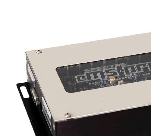
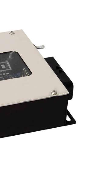
4 4. Installation Overview The Spectre ems-pro standalone engine management system is a programmable microcontroller specifically designed to control electronically fuel injected engines. This system is based on the proven Megasquirt system, which is already running on thousands of engines that range from tiny 2-strokes, to 1000+hp street-driven engines, top speed racing engines, and more! Typical 36-1 crankshaft position wheel and sensor, as found in many Ford engines During this installation, you will mount two temperature sensors (coolant and intake air), attach the Spectre ems-pro harness to your throttle position sensor, and run a vacuum line to the onboard manifold pressure sensor in the Spectre ems-pro. You ll also connect the Spectre ems-pro to your fuel injectors, connect the Spectre ems-pro to your tach source (sensor or device that supplies the Spectre ems-pro with the engine s RPM and position information), and attach the Spectre ems-pro s harness to 12 volt power and grounds. To control ignition timing, the Spectre ems-pro requires a position sensor with at least one trigger per spark event (example: V8 distributor with internal 8-tooth trigger), OR (using the advanced Wheel Decoder mode) evenly-spaced triggers on a crank- or camshaftmounted sensor. Note: If you are using a distributor pickup/sensor, you must disable vacuum or mechanical advance. This means, locking out the distributor advance mechanically, as the ems-pro will now control ignition timing advance. Example of a typical V8 distributor with internal magnetic trigger / pickup wheel At the conclusion of the installation process, you will be ready to tune your engine for proper startup and idling (see Spectre ems-pro Tuning Guide). II. Installation Note: Install tuning software prior to installation of the unit for testing and verification purposes. 1. Selecting a location to mount your Spectre ems-pro The Spectre Spectre ems-pro is not waterproof, it is designed to be installed inside the passenger compartment of your vehicle. Possible mounting locations include: underneath drivers or passenger seat, passenger footwell, or anywhere else the unit can be mounted where it will not be kicked, disturbed, damaged etc. page 2

5 Properly mounted Spectre ems-pro We also recommend using the included rubber feet to mount the unit for vibration resistance. Remember to leave the ECU accessible enough to be able to access the USB and serial communications ports for future tuning and configuration. 2. Wire Harness layout Now, route the wire harness from the Spectre ems-pro location to the necessary input sensors and outputs. Most of the wires in the Spectre ems-pro harness will go to sensors, fuel injectors, etc. under the hood. You will need to find a suitable hole in your car s firewall, or make one, that will allow the Spectre ems-pro harness to be routed from its installation location to the engine compartment. Make sure to use a rubber grommet in any holes the harness passes through, as chafing/rubbing will cause short circuits and tuning difficulty later on. Try to lay out your wiring plan before you drill holes or run the wires through the firewall! For example, on a late model vehicle with factory electronic fuel injection, it s suitable to use the existing harness by tapping into existing wires (e.g., fuel injectors, temp sensors, etc.). On older vehicles originally equipped with a carburetor, this will probably not be an option! Think before you drill a hole! 3. DIP switch configuration In order to make the Spectre ems-pro compatible with as many different engine position sensors as possible, it was built with multiple tach input circuits which are configurable using DIP switches. Locate the DIP switch panel (under the Identification plate on the Spectre ems-pro). Notice that there are two separate dip switches. The first group (SW1) has 8 switches; the second (SW2) has 5 switches. page 3
6 Beginning with SW1 here are the functions for each: Dip Switch Switch Position Description Down/On Up/Off Description Down/On Up/Off Description Down/On Up/Off Description Down/On Up/Off Description Down/On Up/Off Description Down/On Up/Off Functionality Selects either Internal MAP sensor, or External MAP sensor Uses the Spectre ems-pro uses onboard 4-bar MAP sensor. Uses an external MAP sensor which is connected to the MAP wire in the harness Tach Circuit Output select. This switch works with switch 1-7 below to route the signal out of the Opto circuit into the Spectre ems-pro CPU. If you are using a Hall or Optical sensor (square wave) as your engine position input, you want this switch in the DOWN/ON position (example 1-2) Enables the Hall/Opto circuit Disables the Hall/Opto circuit Tach Circuit Output select. If you will use a VR/Magnetic/Inductive pickup sensor for your engine position input to the Spectre ems-pro, this switch must be in the DOWN position (example 1-3) Enables the VR/Magnetic tach input circuit Disables the VR/Magnetic circuit Tach Circuit Output select Enables and inverts the VR/magnetic tach input circuit. Exception: the signal coming from the sensor will be inverted that means: sensor outputs negative voltage = positive signal going into the Spectre ems-pro CPU sensor outputs positive signal = negative signal seen by Spectre ems-pro CPU. This is NOT the same as inverting the polarity (changing the positive and negative wires at the VR sensor) of your VR input circuit Disables the VR/Magnetic circuit Tach Input 5 volt pullup. Used only for Hall/Opto installations. Some installations using square wave (hall/opto) inputs to the Spectre ems-pro will require the pullup enabled as the Spectre ems-pro might draw too much current from the device or sensor providing the signal (for example, in a fuel-only installation you might use a Dash tach signal, or the tach signal from your factory ECU, to drive the Spectre ems-pro and it may need a pullup circuit to keep the signal working properly). Never use BOTH switch 1-5 and 1-6 enabled together, as it will link the 5 volt and 12 volt power circuits together, possibly causing damage to your Spectre ems-pro controller! Applies a 5 volt pullup to tach signal input Tach Input 12 volt pullup. Used only for Hall/Opto installations. Some installations using square wave (hall/opto) inputs to the Spectre ems-pro will require the pullup enabled as the Spectre ems-pro might draw too much current from the device or sensor providing the signal (for example, in a fuel-only installation you might use a Dash tachometer signal, or the tach signal from your factory ECU, to drive the Spectre ems-pro and it may need a pullup circuit to keep the signal working properly). Never use BOTH switch 1-5 and 1-6 enabled together, as it will link the 5 volt and 12 volt power circuits together, possibly causing damage to your Spectre ems-pro controller! Applies a 12 volt pullup to tach signal input page 4
7 Description 1-7 Down/On Up/Off 1-8 Description VR Input to Tach In this switch works in conjunction with switches 1-3 and 1-4 above If either of switches 1-3 or 1-4 are in the DOWN/ON position, this switch also needs to be in the DOWN/ ON position If using a Hall/Optical sensor tach source, this switch must be in the UP/OFF position Cam position sensor input pullup adds a 5 volt pullup signal to the incoming Cam position sensor signal. Only needed if using a cam signal that requires a pullup circuit. Note: the Spectre ems-pro only supports VR/magnetic/inductive pickups for cam signals, however our testing shows that square wave / hall / opto outputs will also work with our VR circuit. Talk to Technical Support if you need help with your cam sensor input. Only a few installations will require a cam sensor input (rotary engines, engines with no missing teeth on their crankshaft position sensor, etc.) Here are the functions for each switch in SW2: 2-1 Description 2-2 Description 2-3 Description 2-4 Description 2-5 Description Ignition Output A 5 volt pullup. Use this if you are driving an ignition transistor (also called ignitor ) that requires a 5 volt signal for triggering. These are usually OEM units, like that in a Mitsubishi Eclipse or an LS1 coilpack. If you are driving an inductive or points output (for example, attaching to the white wire on an MSD ignition), leave this switch in the UP/OFF position. You will use this switch if you are running any kind of ignition output, whether it s a distributor ignition, or wasted spark system. Ignition Output B 5 volt pullup. Note: Use this if you are driving an ignition transistor (also called ignitor ) that requires a 5 volt signal for triggering. If you are driving an inductive or points output (for example, attaching to the white wire on an MSD ignition), leave this switch in the UP/OFF position. You will only use this ignition output only if you are running MORE than one spark output, as with a wasted spark system. Ignition Output C 5 volt pullup. Note above in 2-2 applies here as well. Ignition Output D 5 volt pullup. Note above in 2-2 applies here as well. Enable Bootloader. This switch should ALWAYS remain in the UP/OFF position. It is only used for reloading firmware into your Spectre ems-pro, in the event of future firmware/software upgrades or enhancements. Here are some example DIP switch configurations to get you started: Example 1: Domestic V-8 with magnetic pickup distributor. Magnetic pickup wire from distributor, ne+ goes to ground; ne- wires to ems- Pro tach input. DIP switches as follows: 1, 3, 7 enabled (down/on). All others in off/up position. Example 2: Import 4-cylinder with Hall sensor camshaft mounted sensor. Sensor output wires to ems-pro tach input. DIP switches as follows: 1, 2, 6 (enable switch 6 if your setup requires a 12 volt pullup circuit, or switch 5 for a 5 volt pullup) See included wiring diagrams for other common applications. Also check our website for other diagrams ( com/emspro). 4. Power and Grounds Before you perform wiring tasks, make sure to disconnect battery by removing the negative terminal! Shorted circuits can cause internal damage to your ems-pro! First, take a look at the ground wires on the Spectre ems-pro. Notice that there are eight separate ground leads. The reason for this many leads is so the Spectre ems-pro can reject noise, and carry injector current to ground properly. You may notice that on OEM fuel injected vehicles, multiple ground leads are also used. You can ground the Spectre ems-pro to either a chassis ground, or battery negative terminal. If you use the chassis ground, we recommend inside the passenger compartment, away from engine compartment heat. Test the grounds using an ohm meter when you are finished, (acceptable readings should be less than 1 ohm total resistance or as close to zero as is possible). It is acceptable to group the grounds together into a smaller number of ring terminals for easier installation. We highly recommend soldering the ground wires into the crimp terminals for maximum continuity. It is essential that all engine inputs, temp sensors, TPS, map Sensors share the same electrical ground as the Spectre ems-pro system ground. page 5
8 Next, find a suitable location for your 12 volt power supply. The Spectre ems-pro doesn t require much current (less than 300 milliamps), but it does require the 12 volt source to be hot while the ignition key is in both run and cranking positions. Double check your chosen power source to see that it maintains 12 volts when cranking the starter many 12 volt sources inside the vehicle are NOT powered when the ignition is in the cranking position. In the case of a vehicle already equipped with an OEM ECU, the original 12 volt power to that ECU will suffice for power to the Spectre ems-pro. Note that there are two wires in the Spectre ems-pro harness that require 12 volts. Both can be connected to the same source (the fv12 lead is used to direct noise from the Fuel Injector driver circuitry outside the Spectre ems-pro). At this point, it s a good idea to test power to the unit. Reconnect the negative terminal on the battery. Make sure none of the remaining leads are touching each other or the ground, then power up your unit by turning on the ignition key to the run position. Inside you should see blue LEDs light up indicating the board has power. Once you have completed this step, turn the ignition off and disconnect the negative battery terminal. 5. Intake Air Temperature sensor (IAT) The Intake Air Temperature sensor (also called Manifold Absolute Temperature sensor) is used to measure the temperature of the air entering the combustion chamber. Cold air is more dense than warmer air, thus requiring more fuel to maintain the appropriate air:fuel ratio in your engine. Top: Coolant Sensor (CLT); Bottom: Intake Air Temperature sensor (IAT) First, find a suitable location to install the sensor itself. The best location is in the intake air stream, right before or after the throttle body. The sensor itself is a 3/8 NPT thread (typical GM temp sensor size). Many engines already have a suitable location for installation of this sensor so check yours before drilling and tapping holes unnecessarily! In a naturally aspirated engine, air temp sensor location is less critical than when using forced induction however, you want to install the sensor so it gets the most realistic sampling of intake air possible. If you install the sensor under the hood but not in the intake airstream, the sensor may heat soak causing the Spectre emspro to see hotter air temps and have less accuracy calculating required fuel for given conditions. It s best to have the sensor fitted in the intake tract for best results. Forced induction applications MUST use an air temp sensor inside the intake tract, especially on intercooled engines, for accurate fuel calculations! Note: On forced induction engines, BE SURE to install the intake air temp sensor AFTER any turbochargers, superchargers, or water/alcohol injection systems in order to accurately measure air temperature right before it enters the combustion chamber. Once the sensor has been fitted to the intake air stream, you must connect one of it s two leads to the Spectre ems-pro harness lead labeled IAT. The other sensor lead must go to a good ground if possible, ground this at the same location as the Spectre ems-pro grounds. It s recommended to use one of the Spectre ems-pro ground wires as a return for all three sensors in the engine compartment that require grounding: Coolant Temp, Air Temp, and Throttle Position. Temp sensors do NOT have any particular polarity, so it does not matter which lead gets grounded and which lead attaches to the Spectre ems-pro harness. The ems-pro harness wires for the temperature sensors are color-matched to the pigtails in the Spectre Accessory Kit. 6. Coolant Temperature sensor (CLT) The coolant temperature is used by the Spectre ems-pro to determine whether the engine needs extra fuel when cold starting or during engine warmup. This allows the tuner to adjust the fuel demands of the engine during these periods. First, check your engine for existing locations to install the CLT sensor. Many engines already have a 3/8 NPT fitting for temp sensors used for coolant temp gauges, or for existing ECUs (if the engine was originally fuel injected). It s important to find a location BETWEEN the engine block and thermostat! If the CLT sensor is mounted after the thermostat, it will only see the temperature of the coolant in the radiator, which does not change until the thermostat opens. This causes the ems-pro to miss the warmup period, only seeing cold coolant, making warmup enrichments difficult to page 6
9 tune. If you are installing the Spectre ems-pro on an air-cooled or oil-cooled engine, the CLT sensor can be installed either directly in the engine block or in the oil supply to determine engine temperature. If your engine does not have a suitable location for the CLT sensor, a T-fitting can be used either with existing coolant temp sensor locations, or in a heater hose before it enters the passenger compartment. If you must drain the engine coolant to install the CLT sensor, make sure you are familiar with the proper procedure for refilling, and bleeding air from, your engine s coolant system after you are done. Connecting the CLT sensor to the Spectre ems-pro harness is similar to the IAT sensor: one wire goes to a good ground(same as System ground and an interior location) and the other goes to the harness lead labeled CLT. Temp sensors do NOT have any particular polarity, so it does not matter which lead gets grounded and which lead attaches to the Spectre ems-pro harness. The ems-pro harness wires for the temperature sensors are color-matched to the pigtails in the Spectre Accessory Kit. 7. Throttle Position Sensor (TPS) Next we ll install the Throttle Position Sensor. Hopefully, your engine s throttle body already has a TPS installed, and all you need to do is connect the three wires going to it. The Spectre ems-pro works with *any* 0-5 volt sensors, found in almost every vehicle equipped with a TPS. The TPS works by taking a 5 volt signal from the Spectre ems-pro, routing that voltage through a potentiometer in the TPS, and returning it to the Spectre ems-pro. With a closed throttle, the voltage returned to the Spectre ems-pro is small (0-2 volts). When the throttle is opened, the potentiometer is turned, and the voltage returned to the Spectre ems-pro increases (3-5 volts) thus allowing the Spectre ems-pro to determine the throttle angle at any given time. Later, in the Tuning Guide, we will calibrate the TPS configuration for your engine. It is not important that your TPS reaches exactly zero volts when closed, or 5 volts when opened, only that it increases in voltage with increased throttle opening. ***** The first wire to connect to your TPS is a ground. Like the other sensors, connect this lead to a suitable ground location near the Spectre ems-pro grounds, or even to one of the Spectre ems-pro ground leads itself. The second wire is the TPS sensor s 5 volt power supply which comes from the Spectre ems-pro: this lead is labeled TPS VREF in the Spectre ems-pro wire harness. Connect it to the 5 volt input of the TPS sensor. Typically the center wire in the connector plug is the TPS signal wire (or wiper of the Potentiometer that is used for this application), with the outer two pins being ground and Vref, as you have already determined which of the pins required the ground, you may assume that the other outer pin is where Vref should go. The third and final lead is the sensor return wire, which carries the signal (anywhere from 0 5 volts, depending on throttle position) back to the Spectre ems-pro. The lead in the Spectre ems-pro harness is simply labeled TPS. How to determine which TPS wires go where: Disconnect the TPS, and use a digital multi-meter. Switch it to measure resistance. The resistance between two of the connections will stay the same when the throttle is moved. Find those two - one will be the +5 Vref and the other a ground. The third is the sense wire to the ems-pro. To figure out which wire is the +5 Vref and which is the ground, connect your meter to one of those two connections and the other to the TPS sense connection. If you read a high resistance which gets lower as you open the throttle, the disconnected wire is the one which goes to ground, the other one which had the continuous resistance goes to the +5 Vref from the ems-pro, and the remaining wire is the TPS sense wire. 8. Fuel Injectors Next, we ll connect the Fuel Injectors to the Spectre ems-pro. The fuel injectors, like the temperature sensors, have no specific polarity. Each injector is operated by feeding vehicle power (12 volts) to one lead, and briefly connecting the other lead to ground. The Spectre ems-pro opens your injectors by connecting them briefly to a ground. This way, the Spectre ems-pro does NOT have to supply the voltage to drive the injectors, it only must sink the current passing through them, to a ground. Thus, you must supply the 12 volt power for your injectors. We strongly recommend you use a standard automotive relay (Spectre P/N 7145) to power the fuel injectors with battery voltage, triggered by ignition power. See the ems-pro Wiring Diagram below for proper power wiring for your fuel injectors. Make sure to use an appropriate fuse as close as possible to the power source for your injectors! Once the injectors have power, you must decide how you will connect them to the Spectre ems-pro. The Spectre ems-pro has two driver circuits for injectors. You can connect up to 8 high or low impedance injectors to each driver. You can fire all injectors in batch mode (all together) or you can alternate the firing sequence by installing half of your injectors on one driver circuit, and the other half to the remaining driver circuit. It s up to you to decide how to use the dual injector drivers and wire your injectors. The injector driver circuits are labeled INJ1 and INJ2 in the Spectre ems-pro harness. You may choose to run each bank of cylinders on page 7
10 a V-6 or V-8 engine on individual injector drivers from the ems-pro. Advanced users (turbocharged or rotary engine users) may want to run staged injection, which means a secondary set of injectors are used to add fuel only in certain conditions. When complete, disconnect the fuel injectors from their pigtail connectors until you are ready to start the engine. You will likely crank the engine to test the Tach input, so you do not want to inadvertently add fuel to the cylinders until you are ready to start it the first time! 9. Fuel Pump Relay The Spectre ems-pro harness lead labeled FUEL PUMP triggers the Fuel Pump relay. If your car is not already equipped with a fuel pump relay, do so with an appropriately sized automotive relay (Spectre P/N 7145). The Spectre ems-pro lead is designed to ground the relay s trigger circuit (or coil circuit), and it s wise to supply the trigger circuit s power source from the same ignition source as the Spectre ems-pro s 12 volt source. This way, the fuel pump is turned off when either the ignition is turned off, or the Spectre ems-pro decides to turn off the pump (for example, when there is no RPM signal). This is for safety reasons. Test this circuit by manually applying a ground to the same lead that the Spectre ems-pro s FUEL PUMP lead will connect to (with the ignition on). The fuel pump should activate when this circuit is grounded, and when the ignition power source is active (key on). Once you have completed this step, turn the ignition off and disconnect the negative battery terminal. 10. Oxygen Sensor (also called Exhaust Gas Oxygen sensor) Your installation may have a variety of Oxygen Sensors (or none at all!). It is strongly recommended that you use a wideband oxygen sensor if you plan on tuning the Spectre ems-pro and engine yourself! Narrowband Oxygen Sensors are fine for part throttle driving, but Wide Open Throttle (especially with forced induction, or nitrous applications) needs to be run richer than a 14.7:1 AFR. A wideband oxygen sensor, unlike a narrowband, is capable of measuring a wider range of AFR and will help you develop a more accurate part throttle, and wide open throttle tune. Whether you use a narrowband or wideband sensor, you need to attach the sensor or controller s OUTPUT wire to the Spectre ems-pro harness lead labeled O2. If you are using a wideband oxygen sensor, most likely it will come with a control unit that houses the actual output leads which will connect to your Spectre ems-pro. The Spectre ems-pro can read either a 0-1 volt or 0-5 volt oxygen sensor you will configure the exact type and curve later, when you configure the Spectre ems-pro unit with your SpecTune software. Make sure to follow the Oxygen Sensor Manufacturers directions when installing your Oxygen sensor! Some sensors are sensitive to exhaust heat and require installation a certain distance from the exhaust manifold or turbocharger turbine outlet. Additionally, take care to follow the grounding instructions per manufacturers guide, as the heater element for some Wideband Sensors may be prone to causing noise on its ground return, you may be asked to locate this ground some distance away from your system and sensor grounds. If you are not using an oxygen sensor, snip or tape the O2 lead in the Spectre ems-pro harness so it does not contact ground or power, and secure it with other unused wires in the harness. 11. Engine position sensor input (tach input) Next is the tach input or engine position sensor input. The Spectre ems-pro can receive this signal from a variety of sensor types: VR/ Magnetic/Inductive, or Hall/Optical. Magnetic/Inductive/VR sensors: If your engine uses a Magnetic/Inductive/VR signal for triggering engine position, there will be two wires coming from the position sensor. The sensor itself may either be on the crankshaft, connected to the camshaft (spinning at half engine speed) or in the distributor. For example, a V8 distributor engine typically has a sensor inside the distributor with EIGHT teeth (one for every ignition event). Or, it may have a four tooth sensor on the crankshaft (again, one for every firing event four cylinders fire per every one revolution on a V8 4-cycle engine). The Spectre ems-pro does NOT require an exact number of teeth as ignition events (one thing that separates the Spectre ems-pro from other standalone EMS s), but it DOES require you to know how many teeth are on the position sensor, and what speed the trigger wheel spins (either full or half engine speed). If your sensor has one tooth for every ignition event, you will configure the Spectre ems-pro to run in Distributor mode. If your sensor has more teeth than ignition events per engine cycle, or if it has a wheel with missing teeth (such as a Ford EDIS wheel, with 35 teeth spaced every ten degrees and one missing tooth to denote TDC), you will configure the Spectre ems-pro to run in Wheel Decoder mode. It is important that you know what type of sensor your engine uses and what the tooth pattern on the trigger/sensor is. This information is usually available on web forums, in shop/service manuals, or by looking at the trigger wheels and sensors themselves. If in doubt, contact our Technical Support department for help! 12. Ignition output(s) The Spectre ems-pro lets you configure up to four ignition outputs. A. Distributor engines: Engines that use a distributor to route spark to individual cylinders only require a single spark output to trigger a single ignition coil. Do not, under any circumstances, connect the Spectre ems-pro directly to an ignition coil!! This will cause immediate damage to your unit and void its warranty. Instead, you must use some type of ignition transistor (also called an ignitor ), or a Capacitive Discharge Ignition (such as MSD, Pertronix, Crane, or Jacobs CDI ignition box page 8
11 and coil) system. On most CDI ignition systems, there is a white wire which triggers spark by grounding that wire. This is the wire to connect to the Spectre ems-pro Ignition A lead. B. Wasted Spark or COP engines: Engines that use coilpacks (either one cylinder per coil, or two cylinders per coil which is called wasted spark ) will use more than one spark output from the Spectre ems-pro. Do not, under any circumstances, connect the Spectre ems-pro directly to an ignition coil!! This will cause immediate damage to your unit and void its warranty. You will first need to determine your engines firing order, then connect the ignition outputs to your CDI ignition, or ignition coil transistor, appropriately. How to determine this: For a wasted spark ignition take your firing order (for example, 1,3,4,2) and align the numbers with the two ignition outputs you ll use on a wasted spark four cylinder ignition, ABAB. So, cylinder 1 is attached to the A ignition output, cylinder 3 is connected to the B output, cylinder 4 is ignited by the ignition A output, and cylinder 2 is ignited by the ignition B output. What this means is, on your wasted spark coilpacks, cylinders 1 & 4 are connected to the ignition A coilpack, and cylinders 2 & 3 are connected to the ignition B coilpack. V6 and V8 wasted spark systems are configured the same way: six cylinder systems will use Ignition outputs A, B, and C; wasted spark V8 systems will use ignition outputs A, B, C, and D. When finished, do NOT connect the ignitor to the Spectre ems-pro ignition outputs until you have configured the DIP switches, and the ignition output behavior in the Spectre ems-pro tuning software! The default configuration may inadvertently trigger the ignitor/cdi ignition and cause ignition components, or the Spectre ems-pro, to malfunction! Connect these only after the Spectre ems-pro has been configured, and you are ready to test the system for proper spark. After these installation steps are complete, we recommend starting the engine and tuning a stable idle BEFORE adding features such as nitrous oxide control, two-step rev limiter, etc. Proceed to the Tuning guide for First Start instructions. page 9
12 Glossary Description 4-Bar Definition A measurement of a pressure sensor s usable measurement range. 4-bar means 4 atmospheres or the equivalent of 44psi of boost on a turbocharged engine 5v Pullup 5-volt pullup. Some Hall/Opt sensors require you to enable the 5 volt pullup option via DIP switch 1-5 5v signal Cam position sensor CDI COP CPU/ECU DIP switch ECU EDIS wheel Engine position input Engine position sensor Firmware Hall Ignition transistor Ignitor Inductive pickup sensor Magnetic input MAP sensor Also called TTL or ECU triggering: the use of a 5 volt pulse to trigger ignition events Sensor mounted to camshaft or that runs at camshaft speed, which gives a single-tooth signal for every camshaft revolution Capacitive Discharge Ignition Coil-On-Plug. This is an ignition system configuration that uses one coil for each cylinder, triggered separately by the engine management system. Central Processor Unit / Engine Control Unit. Other names for the computer that manages your engine and powertrain. Switches on the endplate of the ems-pro that allow a user to configure MAP sensor type (internal or external); tach input signal type (VR/magnetic/inductive or Hall/Optical); spark output configuration; and enabling the bootloader program Engine Control Unit. Another name for an ems-pro, or any other powertrain control computer. Ford s typical crankshaft position sensor trigger wheel for wasted spark 4-, 6, and 8-cylinder engines. The signal, or wire carrying the signal, that tells the ems-pro what RPM the engine is turning, and when Top Dead Center occurs (for accurate ignition timing) Component or components that determine engine speed and position, and provide that information to the ems-pro The Operating System software that runs on your ems-pro computer. Similar to Linux or MS-Windows on a Personal Computer. Type of sensor that outputs a square wave signal. A device that lets the ems-pro remotely trigger an ignition coil or coilpack. Same as Ignition Transistor above. Same as VR sensor the device that reads a toothed-wheel and outputs an AC sine wave to the ems-pro s tach input circuit. Same as VR input above. Manifold Absolute Pressure sensor. Senses air pressure in the intake manifold, used by the ems-pro to determine how much load is being placed on the engine. This sensor is critical to proper air:fuel mixtures at all times. Narrowband O2 sensor Oxygen sensor that measures free Oxygen in the exhaust stream. Narrowband sensors can connect directly to the ems-pro, but only allow measurement of a stoich air-fuel ratio (14.7:1 for gasoline engines). Fine for part throttle closed-loop tuning, but not good for WOT or forced induction applications. OEM Opto Square wave Tach input Tach output VR input Wasted spark Wheel decoder mode Wideband O2 sensor Original Equipment Manufacturer. Type of sensor that outputs a square wave signal. The signal observed coming from Hall/Optical sensors, or a signal that switches between High (usually 12 or 5 volts DC) and Low (ground or zero volts) Signal (or signal wire) that tells the ems-pro engine position and speed information. Can be square wave (Hall/Optical sensors), or AC sine wave (magnetic/inductive sensors) The wire in the ems-pro harness that can supply a signal to an aftermarket tachometer or other electronics that require a tach input signal Variable Reluctance Input: the signal from a magnetic or inductive sensor, which reads a toothed-wheel, and is fed to the ems-pro via the tach input wire in the ems-pro harness. Wasted Spark is an ignition system configuration that uses one coil for paired cylinders, triggered in pairs by the engine management system. ems-pro software configuration for reading single or multiples toothed-wheels Oxygen sensor, which usually requires controller, that measures free Oxygen in the exhaust stream. A Wideband O2 sensor is capable of measuring a wider range of air-fuel ratios, and is good to use when tuning forced induction engines. page 10
13
14
15

16
17
18
MSD 6LS-2 Ignition Controller for Carbureted and EFI LS 2/LS 7 Engines PN 6012
 MSD 6LS-2 Ignition Controller for Carbureted and EFI LS 2/LS 7 Engines PN 6012 ONLINE PRODUCT REGISTRATION: Register your MSD product online. Registering your product will help if there is ever a warranty
Megasquirt EX, Installation Instructions document revision 1.4 (Includes also the version equipped with wasted-spark ignition)
") Megasquirt EX, Installation Instructions document revision 1.4 (Includes also the version equipped with wasted-spark ignition) General Megasquirt EX is a programmable engine control system, based on Megasquirt
Megasquirt EX, Installation Instructions document revision 1.4 (Includes also the version equipped with wasted-spark ignition) General Megasquirt EX is a programmable engine control system, based on Megasquirt
MSD LS-1/LS-6 Controller for Carbureted and EFI Gen III Engines PN 6010
 MSD LS-1/LS-6 Controller for Carbureted and EFI Gen III Engines PN 6010 Parts Included 1 Ignition Controller, PN 6010 1 Pro-Data+ Software CD 1 Harness 1 Parts Bag 6 Timing Modules Optional Accessories
MSD 6-Hemi Controller for Carbureted and EFI Hemi Engines PN 6013
 MSD 6-Hemi Controller for Carbureted and EFI Hemi Engines PN 6013 Parts Included: 1 - Ignition Controller, PN 6013 1 - Pro-Data+ Software CD 1 - Parts Bag 1 - Mounting Template Optional Accessories: Hand
MSD 6-Mod Controller for Carbureted and EFI Gen III Engines PN 6011
 MSD 6-Mod Controller for Carbureted and EFI Gen III Engines PN 6011 ONLINE PRODUCT REGISTRATION: Register your MSD product online. Registering your product will help if there is ever a warranty issue with
E-STREET 2 EFI IGNITION CONTROL KIT Part #3674, 3675, 3676, 3679, 3680 INSTALLATION INSTRUCTIONS
 E-STREET 2 EFI IGNITION CONTROL KIT Part #3674, 3675, 3676, 3679, 3680 INSTALLATION INSTRUCTIONS PLEASE study these instructions carefully before beginning this installation. Most installations can be
MSD Pro-Billet Digital E-Curve Distributor Ford 289/302 PN U.S. Patent
 MSD Pro-Billet Digital E-Curve Distributor Ford 289/302 PN 8503 - U.S. Patent 6820602 ONLINE PRODUCT REGISTRATION: Register your MSD product online and you ll be entered in our monthly 8.5mm Super Conductor
MSD 6-Mod Controller for Carbureted and EFI Gen III Engines PN 6011
 MSD 6-Mod Controller for Carbureted and EFI Gen III Engines PN 6011 Parts Included 1 - Ignition Controller, PN 6011 1 - Pro-Data+ Software CD 1 - Harness 1 - Parts Bag 1-2-Bar MAP Sensor Optional Accessories
MSD Pro-Billet Digital E-Curve Distributor Ford 289/302 PN U.S. Patent
 MSD Pro-Billet Digital E-Curve Distributor Ford 289/302 PN 8503 - U.S. Patent 6820602 Important: Read these Instructions before attempting the installation. Parts Included: 1 - Digital E-Curve Distributor
EFI HARNESS KIT , & Kit Contents: Power Harness : All Kits
 EFI HARNESS KIT 558-500, 558-501 & 558-502 Kit Contents: Main Harness 558-102: Kits 558-500 558-103: Kits 558-501 & 502 Power Harness 558-308: All Kits Injector Harness 558-200: Kits 558-500 & 502 558-201:
MSD-8 Plus Ignition PN 7805
 MSD-8 Plus Ignition PN 7805 Note: Solid Core spark plug wires cannot be used with an MSD Ignition. Parts Included: 1 - MSD-8 Plus Ignition 1 - Mag Pickup Extension Harness, PN 8860 4 - Vibration Mounts
MALLORY FIRESTORM CD MULTI COIL HARDWARE INSTALLATION - PN 69050S / 69050R
 FORM 69050S/R MALLORY FIRESTORM CD MULTI COIL HARDWARE INSTALLATION - PN 69050S / 69050R To ensure you are using the most current instruction sheet, please visit www.malloryfirestorm.com. CAUTION! The
MSD Single Cylinder Programmable Ignition PN 4217
 MSD Single Cylinder Programmable Ignition PN 4217 Parts Included: 1 - PN 4217 1 - PN 4217 Wire Harness 1 - CD Rom 9609 1 - Parts Bag 1 - Serial Cable WARNING: During installation, disconnect the battery
MALLORY FIRESTORM CD MULTI COIL HARDWARE INSTALLATION - PN 69150C / 69150R
 FORM 69150C/R MALLORY FIRESTORM CD MULTI COIL HARDWARE INSTALLATION - PN 69150C / 69150R To ensure you are using the most current instruction sheet, please visit www.malloryfirestorm.com. CAUTION! The
MSD Pro-Billet Chevrolet HEI Distributor PN 83651, PN 8365/83653
 MSD Pro-Billet Chevrolet HEI Distributor PN 83651, PN 8365/83653 ONLINE PRODUCT REGISTRATION: Register your MSD product online. Registering your product will help if there is ever a warranty issue with
CAUTION: CAREFULLY READ INSTRUCTIONS BEFORE PROCEEDING
 Daytona Sensors LLC Engine Controls and Instrumentation Systems Installation Instructions for Wide-Band Exhaust Gas Oxygen Sensor Interface CAUTION: CAREFULLY READ INSTRUCTIONS BEFORE PROCEEDING OVERVIEW
Controller Ground (dual black 12awg) should be connected to chassis ground as close as possible to the battery.
 should be connected to chassis ground as close as possible to the battery.") 1. Overview The Maximizer 4 progressive nitrous controller operates one or two separate stages of nitrous based on either time, RPM, MPH, throttle percentage or boost pressure. Whether your engine is naturally
1. Overview The Maximizer 4 progressive nitrous controller operates one or two separate stages of nitrous based on either time, RPM, MPH, throttle percentage or boost pressure. Whether your engine is naturally
MSD Pro-Billet Digital E-Curve Distributor PN U.S. Patent
 MSD Pro-Billet Digital E-Curve Distributor PN 8394 - U.S. Patent 6820602 ONLINE PRODUCT REGISTRATION: Register your MSD product online. Registering your product will help if there is ever a warranty issue
MSD Pro-Billet Ready to Run Distributor Ford Y-Block, PN 8383 Ford FE, PN 8595
 MSD Pro-Billet Ready to Run Distributor Ford Y-Block, PN 8383 Ford FE, PN 8595 ONLINE PRODUCT REGISTRATION: Register your MSD product online and you ll be entered in our monthly 8.5mm Super Conductor Spark
MSD-8 Plus Ignition PN 7805
 MSD-8 Plus Ignition PN 7805 ONLINE PRODUCT REGISTRATION: Register your MSD product online. Registering your product will help if there is ever a warranty issue with your product and helps the MSD R&D team
INSTALLATION INSTRUCTIONS. Revision 3.1.1
 INSTALLATION INSTRUCTIONS Revision 3.1.1 Table of Contents INTRODUCTION... 4 INSTALLATION OVERVIEW... 5 Included Parts... 6 DEVICE WIRING... 7 Required Parts... 7 Guidelines... 7 Wiring Diagram... 8 Compatible
FAST XIM. XIM Unit Installation
 1 INSTRUCTIONS XIM Thank you for choosing products; we are proud to be your manufacturer of choice. Please read this instruction sheet carefully before beginning installation, and also take a moment to
MSD Stacker-4 (4-Channel), PN 7010 Stacker-8 (8-Channel), PN 7020
, PN 7010 Stacker-8 (8-Channel), PN 7020") INSTALLATION INSTRUCTIONS 1 MSD Stacker-4 (4-Channel), PN 7010 Stacker-8 (8-Channel), PN 7020 Important: Read these instructions before attempting this installation! Parts Included: 1 - MSD Stacker Ignition
INSTALLATION INSTRUCTIONS 1 MSD Stacker-4 (4-Channel), PN 7010 Stacker-8 (8-Channel), PN 7020 Important: Read these instructions before attempting this installation! Parts Included: 1 - MSD Stacker Ignition
MSD Pro-Billet Digital E-Curve Distributor PN U.S. Patent
 MSD Pro-Billet Digital E-Curve Distributor PN 8394 - U.S. Patent 6820602 Important: Read these Instructions before attempting the installation. Parts Included: 1 - Digital E-Curve Distributor 1 - Rotor,
MSD Pro-Billet Chevrolet HEI Distributor PN 8365
 MSD Pro-Billet Chevrolet HEI Distributor PN 8365 ONLINE PRODUCT REGISTRATION: Register your MSD product online and you ll be entered in our monthly 8.5mm Super Conductor Spark Plug Wire give-away! Registering
MegaSquirt III for LS Style Engines. Hardware Install. 1. Disconnect and remove the battery from the vehicle.
 MegaSquirt III for LS Style Engines MegaSquirt controllers are experimental devices intended for educational purposes. MegaSquirt controllers are not for sale or use on pollution controlled vehicles. Check
MSD Pro-Billet Ready-to-Run Chrysler Distributor PN /354 Early Hemi PN Early Hemi
 MSD Pro-Billet Ready-to-Run Chrysler Distributor PN 8391-331/354 Early Hemi PN 8389-392 Early Hemi ONLINE PRODUCT REGISTRATION: Register your MSD product online. Registering your product will help if there
Speed-Pro EFI Installation Manual
 Speed-Pro EFI Installation Manual Speed-Pro Electronics Installation Manual Page The wiring harness is labeled on each of the connectors to simplify installation. Your application may not require the use
MSD Pro-Billet Ready-to-Run Chevrolet V8 Distributor, PN 8360 Chevrolet 348, 409 Distributor, PN 8393
 MSD Pro-Billet Ready-to-Run Chevrolet V8 Distributor, PN 8360 Chevrolet 348, 409 Distributor, PN 8393 ONLINE PRODUCT REGISTRATION: Register your MSD product online and you ll be entered in our monthly
MaxxECU quickstart guide ( )
") Be a tuning mastermind. Like us. MaxxECU quickstart guide (2019-02-01) Online help! maxxecu.com/support Wiring diagrams Installation help Pinout Support maxxecu.com/support Legal disclaimer All performance
Be a tuning mastermind. Like us. MaxxECU quickstart guide (2019-02-01) Online help! maxxecu.com/support Wiring diagrams Installation help Pinout Support maxxecu.com/support Legal disclaimer All performance
MSD Pro-Billet Small Diameter Ready-to-Run Ford V8 Distributor PN 8350/83503; 351C-460, PN 8354; 351W PN 8352/83523; 289/302
 MSD Pro-Billet Small Diameter Ready-to-Run Ford V8 Distributor PN 8350/83503; 351C-460, PN 8354; 351W PN 8352/83523; 289/302 ONLINE PRODUCT REGISTRATION: Register your MSD product online. Registering your
MegaSquirt III for Gen 3 HEMI. Hardware Install THE FOLLOWING SENSOR PART NUMBERS APPLY TO ALL HARNESSES FOR ENGINES 2004 TO CURRENT:
 MegaSquirt III for Gen 3 HEMI MegaSquirt controllers are experimental devices intended for educational purposes. MegaSquirt controllers are not for sale or use on pollution controlled vehicles. Check the
MSD Pro-Billet Ready-to-Run Ford Flathead, PN 8573
 MSD Pro-Billet Ready-to-Run Ford Flathead, 1949-1953 PN 8573 ONLINE PRODUCT REGISTRATION: Register your MSD product online. Registering your product will help if there is ever a warranty issue with your
MSD Pro-Billet Ready-to-Run Chrysler V8 Distributor PN 8388; 318, 340, 360, PN 8386; 383, 400 PN 8387; 426, 440
 MSD Pro-Billet Ready-to-Run Chrysler V8 Distributor PN 8388; 318, 340, 360, PN 8386; 383, 400 PN 8387; 426, 440 ONLINE PRODUCT REGISTRATION: Register your MSD product online. Registering your product will
MFI Pro - Instructional Manual (Toyota 1uzfe) Version 06.01
 Version 06.01") Tel: 011 3971953 - Fax: 011 3978197 - info@gotech.co.za www.got e ch.c o.za MFI Pro - Instructional Manual (Toyota 1uzfe) Version 06.01 Index: Introduction 1 Before You Begin 1 Basic Tools Required 2 Basic
Tel: 011 3971953 - Fax: 011 3978197 - info@gotech.co.za www.got e ch.c o.za MFI Pro - Instructional Manual (Toyota 1uzfe) Version 06.01 Index: Introduction 1 Before You Begin 1 Basic Tools Required 2 Basic
Ford EV6 Injector Adapter Harness User Manual
 Ford EV6 Injector Adapter Harness User Manual 30-3805- THIS PRODUCT IS LEGAL IN CALIFORNIA FOR RACING VEHICLES ONLY AND SHOULD NEVER BE USED ON PUBLIC HIGHWAYS. AEM Performance Electronics AEM Performance
GM Throttle Body Adapter Harness User Manual
 GM Throttle Body Adapter Harness User Manual 30-3809-01 THIS PRODUCT IS LEGAL IN CALIFORNIA FOR RACING VEHICLES ONLY AND SHOULD NEVER BE USED ON PUBLIC HIGHWAYS. AEM Performance Electronics AEM Performance
INSTALLATION INSTRUCTIONS. Revision 4.0.3
 INSTALLATION INSTRUCTIONS Revision 4.0.3 Table of Contents INTRODUCTION... 3 INSTALLATION OVERVIEW... 4 Included Parts... 5 DEVICE WIRING... 6 Required Parts... 6 Guidelines... 6 Wiring Diagram... 7 Engine
WOLF3D. Installation Manual. Version 4.57 Engine Management System with WIDEBAND AFR. Revision Number 1.004
 WOLF3D Version 4.57 Engine Management System with WIDEBAND AFR Installation Manual Revision Number 1.004 Printed January 27, 2016 CONTENTS 1 Introduction... 5 2 ECU... 6 2.1 Mounting the ECU... 6 2.2 Diagnostic
Asynchronous Restriking CDI 2 channel
 Asynchronous Restriking CDI 2 channel Parts List ARC-2 module Decals Power Cable Fuse Specifications Operating Voltage: 8-20V Operating Current: Max Operating RPM: Ambient Temp range: Ignition inputs:
Installation Instructions for: EMS P/N and U Honda S2000
 Installation Instructions for: EMS P/N 30-1052 and 30-1052U 00-04 Honda S2000! WARNING: This installation is not for the tuning novice nor the PC illiterate! Use this system with EXTREME caution! The AEM
MSD Pro-Billet Ready-to-Run Chrysler V8 Distributor PN 8388; 318, 340, 360, PN 8386; 383, 400 PN 8387; 426, 440
 MSD Pro-Billet Ready-to-Run Chrysler V8 Distributor PN 8388; 318, 340, 360, PN 8386; 383, 400 PN 8387; 426, 440 ONLINE PRODUCT REGISTRATION: Register your MSD product online and you ll be entered in our
Glossary. 116
 Sequential Fuel Injection Sequential means that each injector for each cylinder is triggered only one time during the engine s cycle. Typically the injector is triggered only during the intake stroke.
1. Index. LS Wiring Harness. 2. Presentation Warnings and Warranty Terms Overview Labels...7
 OWNER S MANUAL 1. Index 2. Presentation...4 3. Warnings and Warranty Terms...5 4. Overview...6 5. Labels...7 6. Diagrams...7 6.1 FT500/FT500 Aux - Inputs/outputs...7 6.2 Nano WB O2 #1...8 6.3 Nano WB
Ford Coyote Main Harness and Harness Kit PN , , and
 Ford Coyote Main Harness and Harness Kit PN 558-110, 550-619, and 550-625 This wiring harness interfaces a Holley EFI ECU to a Ford Coyote engine that has either had the cam VVT hardware locked out or
PLATINUM. Sport Haltech 13B Terminated Engine Harness QUICK START GUIDE
 PLATINUM Sport 1000 Haltech 13B Terminated Engine Harness QUICK START GUIDE HALTECH HEAD OFFICE: PH: +612 9729 0999 FAX: +612 9729 0900 EMAIL: sales@haltech.com HALTECH US OFFICE: EMAIL: usa@haltech.com
GENERAL MOTORS SERVICE PARTS OPERATION 6200 Grand Pointe Drive, Grand Blanc, MI 48439
 LS IGNITION CONTROLLER 19355418 Ignition Control for Carbureted LS Series Engines (24x Crankshaft Index/1x Camshaft Index, 58x Crankshaft Index/4x Camshaft Index) Parts Included Quantity Ignition Controller
Innovative Racing Electronics
 FOR IMMEDIATE RELEASE Contact: Dan Rudd Phone: 407.330.9727 FAX: 407.322.8632 E-Mail: sales@mpsracing.com Web: www.mpsracing.com Holley Commander 950 Universal 4 Cylinder Fuel Injection Kit Sanford, Florida,
MSD Marine Ignitions 6M-2L, PN 6560
 MSD Marine Ignitions 6M-2L, PN 6560 ONLINE PRODUCT REGISTRATION: Register your MSD product online. Registering your product will help if there is ever a warranty issue with your product and helps the MSD
PLATINUM Sport Haltech GM LS1 / LS6 Terminated Engine Harness (HT045650) QUICK START GUIDE
 QUICK START GUIDE") PLATINUM Sport 2000 Haltech GM LS1 / LS6 Terminated Engine Harness (HT045650) QUICK START GUIDE LIMITED WARRANTY Lockin Pty Ltd trading as Haltech warrants the Haltech TM Programmable Fuel Injection System
PLATINUM Sport 2000 Haltech GM LS1 / LS6 Terminated Engine Harness (HT045650) QUICK START GUIDE LIMITED WARRANTY Lockin Pty Ltd trading as Haltech warrants the Haltech TM Programmable Fuel Injection System
Installation Instructions for: EMS P/N Honda S2000
 Installation Instructions for: EMS P/N 30-6052 2000-2005 Honda S2000! WARNING: This installation is not for the tuning novice nor the PC illiterate! Use this system with EXTREME caution! The AEM EMS System
Fuel Delivery Requirements
 held Controller the Go EFI System creates a base fuel MAP to get the engine running. Then the self tuning programming will fine tune the MAP to produce optimum power and performance. Through the use of
Thank you for your purchase Off-ROad NOtice: PROduct WaRNiNgs:
 Thank you for your purchase. Please, read the instructions and watch the video before installing the JMS Progressive N20 Controller. Configuration and installation videos are available online: www.jms-nos.com.
GM Stepper Idle Adapter User Manual
 GM Stepper Idle Adapter User Manual 30-3805-07 THIS PRODUCT IS LEGAL IN CALIFORNIA FOR RACING VEHICLES ONLY AND SHOULD NEVER BE USED ON PUBLIC HIGHWAYS. AEM Performance Electronics AEM Performance Electronics,
CAUTION: CAREFULLY READ INSTRUCTIONS BEFORE PROCEEDING
 Daytona Sensors LLC Engine Controls and Instrumentation Systems Installation Instructions for WEGO II Wide-Band Exhaust Gas Oxygen Sensor Interface Methanol Version CAUTION: CAREFULLY READ INSTRUCTIONS
MSD Pro-Billet Front Mount Ford Flathead Distributor 2-Bolt, , PN Bolt, , PN 8353
 MSD Pro-Billet Front Mount Ford Flathead Distributor 2-Bolt, 1942-1948, PN 8351 3-Bolt, 1932-1941, PN 8353 ONLINE PRODUCT REGISTRATION: Register your MSD product online. Registering your product will help
Before continuing with the installation, here are a few definitions you should be aware of:
 MSD Ford Billet Distributors PN 8473: 2.3L, PN 8580: 351C, 351M, 400, 429, 460 PN 8582: 289, 302, PN 8584: 351W PN 85805: 351W w/edelbrock Victor Jr. Intake Important: Read these instructions before attempting
MSD Pro-Billet Chevrolet V8 Distributor with Slip Collar, PN Extra Tall, PN 8547 with Locked-Out Timing, PN 85501
 MSD Pro-Billet Chevrolet V8 Distributor with Slip Collar, PN 85561 Extra Tall, PN 8547 with Locked-Out Timing, PN 85501 ONLINE PRODUCT REGISTRATION: Register your MSD product online. Registering your product
Lingenfelter ECSS-001 Ethanol Content Sensor Signal Simulator Installation & Operating Instructions
 Lingenfelter ECSS-001 Ethanol Content Sensor Signal Simulator Installation & Operating Instructions PN: L460350085 Revision - 1.6 Lingenfelter Performance Engineering 1557 Winchester Road Decatur, IN 46733
Installation Instructions for: DT2-AF2 Dual Channel & DT2-AF1 Single Channel Wide Band O2 Sensor Controller for A/F (Lambda) Measurement
 Measurement") Installation Instructions for: DT2-AF2 Dual Channel & DT2-AF1 Single Channel Wide Band O2 Sensor Controller for A/F (Lambda) Measurement WARNING: This installation is not for the electrically or mechanically
Installation Instructions for: DT2-AF2 Dual Channel & DT2-AF1 Single Channel Wide Band O2 Sensor Controller for A/F (Lambda) Measurement WARNING: This installation is not for the electrically or mechanically
POLESTAR HS Management System
 POLESTAR HS Management System Installation Instructions This document contains the information needed to install and adjust the POLESTAR HS Engine Management System. It assumes that the system already
MSD Pro-Billet Small Diameter Chevrolet V8 Distributor PN 8570
 MSD Pro-Billet Small Diameter Chevrolet V8 Distributor PN 8570 ONLINE PRODUCT REGISTRATION: Register your MSD product online. Registering your product will help if there is ever a warranty issue with your
QUICKSTART MANUAL SNIPER EFI INSTALLATION INSTRUCTIONS
 550-510, 550-511, & 550-516 QUICKSTART MANUAL SNIPER EFI INSTALLATION INSTRUCTIONS Congratulations on your purchase of a new Sniper EFI Throttle Body System built by craftsmen to exacting standards in
OMEM200 Tuning Manual 3v Series ECU. Tuning Manual OMEM200.
 200 Series ECU Tuning Manual OMEM200 www.omextechnology.com 0 1 Introduction... 3 1.1 What this manual covers... 3 1.2 Notation Used in This Manual... 3 2 Software... 4 3 Sensor Setup... 5 3.1 Throttle
ELITE 1000/1500 Dodge SRT QUICK START GUIDE HT
 E N G I N E M A N A G E M E N T S Y S T E M S ELITE 1000/1500 Dodge SRT4 03-05 QUICK START GUIDE HT-140940 LIMITED WARRANTY Lockin Pty Ltd trading as Haltech warrants the HaltechTM Programmable Fuel Injection
MSD Circle Track LS Ignition Control PN 6014CT
 MSD Circle Track LS Ignition Control PN 6014CT ONLINE PRODUCT REGISTRATION: Register your MSD product online. Registering your product will help if there is ever a warranty issue with your product and
CAUTION: READ INSTRUCTIONS CAREFULLY BEFORE STARTING INSTALLATION
 V-Twin MFG. VT No. 32-9500 V-TECH 1 IGNITION KIT, SINGLE FIRE FITS EV SHOVEL, XL THRU 1997 VT No. 32-9503 V-TECH 1 IGNITION KIT, SINGLE FIRE FITS EV, SHOVEL, XL, WITH COIL AND WIRES This is a custom application
MSD Circle Track Ignition PN 6427
 MSD Circle Track Ignition PN 6427 ONLINE PRODUCT REGISTRATION: Register your MSD product online. Registering your product will help if there is ever a warranty issue with your product and helps the MSD
I N S T A L L A T I O N I N S T R U C T I O N S TIMING COMMANDER Interface Gauge Ver 7
 I N S T A L L A T I O N I N S T R U C T I O N S 103033 TIMING COMMANDER Interface Gauge Ver 7 This product is designed to interface with the airtemp (IAT) sensor in your vehicle AND your tuner software
TurboMinis.co.uk. Fuel Injection for the 5 Port A-Series. Paul Sturgess Rod Sugden
 TurboMinis.co.uk Fuel Injection for the 5 Port A-Series Paul Sturgess Rod Sugden Version: Draft 2 December 2010 Version Control Version Date Author Comments Draft December 2009 Paul S 1st Draft Draft 2
PIMP Ford 5.0 Harness Installation Manual. Part Number: PM-75
 PIMP Ford 5.0 Harness Installation Manual Part Number: PM-75 Ron Francis Wiring 200 Keystone Rd Suite 1 Chester, PA 19013 800-292-1940 www.ronfrancis.com Pre-Installation Notes: This system is designed
AEROMOTIVE Part # INSTALLATION INSTRUCTIONS
 AEROMOTIVE Part # 16303 INSTALLATION INSTRUCTIONS CAUTION: Installation of this product requires detailed knowledge of automotive systems and repair procedures. We recommend that this installation be carried
Ford Coyote Non-VVT Main Harness PN
 Ford Coyote Non-VVT Main Harness PN 558-114 This wiring harness interfaces a Holley EFI ECU to a Ford Coyote engine that has had the cam VVT hardware locked out. It is meant to be used in conjunction with
PLUG & PLAY. Quick Start Guide. GM LS 58X Drop On Harness. MS3Pro ULTIMATE
 Quick Start Guide PLUG & PLAY GM LS 58X Drop On Harness MS3Pro ULTIMATE For GM LS Engines with 58X Crank Triggers Thank you for your purchase and support for American made products! We have designed this
AEROMOTIVE Part # INSTALLATION INSTRUCTIONS
 AEROMOTIVE Part # 16303 INSTALLATION INSTRUCTIONS CAUTION: Installation of this product requires detailed knowledge of automotive systems and repair procedures. We recommend that this installation be carried
Installation Instructions for: EMS P/N Eclipse Turbo, Talon Tsi, Laser RS Galant VR4
 Installation Instructions for: EMS P/N 30-6300 1990-1994 Eclipse Turbo, Talon Tsi, Laser RS Galant VR4 Thank you for purchasing an AEM Engine Management System. The AEM Engine Management System (EMS) is
WOT Box Installation Instructions VW / Audi
 Connector Pinout Pin Color AWG Name WOT Box Installation Instructions VW / Audi Description 1 Yellow 18 RPM Connect to Fuel Injector Drive Signal or Ignition Control Signal (varies by car model) 2 Black
MS3-Pro LSx Drop On Harness
 24x MS3-Pro LSx Drop On Harness For engines with 24X crank triggers Thank you for buying our drop on wiring harness! We have designed this harness to support anything from a stock motor swapped into a
Gen III HEMI Harness PN or
 Gen III HEMI Harness PN 558-106 or 558-107 This wiring harness interfaces a Holley EFI ECU to a Gen III HEMI engine. It is meant to be used in conjunction with an injector harness, a coil harness, and
MSD 7AL-3, Ignition Control PN 7230
 MSD 7AL-3, Ignition Control PN 7230 Important: Read the instructions before attempting the installation. Parts Included: 1-7AL-3, PN 7230 1 - Parts bag (wires and connectors) 4 - RPM Modules 3000, 7000,
CAUTION: CAREFULLY READ INSTRUCTIONS BEFORE PROCEEDING
 Daytona Sensors LLC Engine Controls and Instrumentation Systems Installation Instructions for Wide-Band Exhaust Gas Oxygen Sensor Interface CAUTION: CAREFULLY READ INSTRUCTIONS BEFORE PROCEEDING OVERVIEW
MSD Pro-Billet Chrysler Distributor PN Early Hemi
 MSD Pro-Billet Chrysler Distributor PN 83891-392 Early Hemi ONLINE PRODUCT REGISTRATION: Register your MSD product online. Registering your product will help if there is ever a warranty issue with your
TELORVEK II RJ-32 Big Block RamJet Fuel Injection System
 Page #1 TELORVEK II RJ-32 Big Block RamJet Fuel Injection System This wiring system is compatible with the GM Performance part big block Ramjet 502 engine. The harness is designed to dress up the appearance
Mallory HyFire Electronic Ignition Control
 Mallory HyFire Electronic Ignition Control PN 690 Parts Included: 1 - Ignition 1 - Harness, Mag Pickup 1-18" Ground Wire 1-100V/1A Diode 4 - Mounting Screws WARNING: During installation, disconnect the
PHOENIX TACHOMETER WITH OLED DISPLAY
 PHOENIX TACHOMETER WITH OLED DISPLAY REV A0031418 PROGRAMMABLE TACHOMETER WIRING Standalone tachometers with AMP plugs are incandescent perimeter, backlit or LED backlit. Incandescent bulbs will be in
STREET/RACE DISTRIBUTOR
 Installation Instructions for STREET/RACE DISTRIBUTOR CAUTION: READ INSTRUCTIONS CAREFULLY BEFORE STARTING INSTALLATION INTRODUCTION The Crane Cams street/race distributor is a high precision system intended
G - TESTS W/CODES - 2.2L
 G - TESTS W/CODES - 2.2L 1994 Toyota Celica 1994 ENGINE PERFORMANCE Toyota 2.2L Self-Diagnostics Celica INTRODUCTION If no faults were found while performing F - BASIC TESTING, proceed with self-diagnostics.
1. Index. PRO600 Wiring Harness. 2. Presentation Warnings and Warranty Terms Overview PRO600 Harness...6
 OWNER S MANUAL 1. Index 2. Presentation...4 3. Warnings and Warranty Terms...5 4. Overview...6 4.1 PRO600 Harness...6 5. Versions and components...7 5.1 PRO600 components...7 6. Labels...8 7. Diagrams...9
Mallory HyFire Electronic Ignition Control
 Mallory HyFire Electronic Ignition Control PN 690 Parts Included: 1 - Ignition 1 - Harness, Mag Pickup 1-18" Ground Wire 1-100V/1A Diode 4 - Mounting Screws WARNING: During installation, disconnect the
Installation Instructions for: EMS P/N Ford Mustang 5.0L
 Installation Instructions for: EMS P/N 30-1401 1994-95 Ford Mustang 5.0L! WARNING: This installation is not for the tuning novice nor the PC illiterate! Use this system with EXTREME caution! The AEM EMS
Fuel Injection. Instruction Manual
 FiTech TM Fuel Injection Instruction Manual for the following Go EFI Systems 30001, 30002, 30004, 30012, 30061, 30062 & 30064 This Quick Start Manual is designed to get you up and running with the Go EFI
INSTRUCTION MANUAL G-Surge Tank #40007, #40008 & #40009
 FiTech Fuel Injection INSTRUCTION MANUAL Tank #40007, #40008 & #40009 Warning: Caution must be observed when installing any product involving fuel system parts or gas tank modifications. Work in a well
MSD Pro-Billet Chevrolet HEI Distributor PN 8365
 MSD Pro-Billet Chevrolet HEI Distributor PN 8365 ONLINE PRODUCT REGISTRATION: Register your MSD product online. Registering your product will help if there is ever a warranty issue with your product and
TOURING Models
 P/N FI-1252HPST Patent Numbers: 7,000,599 & 7,124,742 Electronic Jet Kit Instructions Thank you for choosing the Techlusion Electronic Jet Kit, the TFI. This TFI model is ONLY usable for the following
MSD Pro-Billet Chevrolet V8 Tach Drive Distributor PN 8571 with Vacuum Advance, PN 8572
 MSD Pro-Billet Chevrolet V8 Tach Drive Distributor PN 8571 with Vacuum Advance, PN 8572 ONLINE PRODUCT REGISTRATION: Register your MSD product online. Registering your product will help if there is ever
MSD Pro-Billet Chevrolet HEI Distributor PN 8365
 MSD Pro-Billet Chevrolet HEI Distributor PN 8365 Important: Read these instructions before attempting the installation. Parts Included: 1 - Pro-Billet Distributor, PN 8365 1 - Rotor, PN 84101 1 - Distributor
Installation Instructions for: EMS P/N Toyota MR2 Turbo Toyota Celica All Trac
 Installation Instructions for: EMS P/N 30-1120 1991-1992 Toyota MR2 Turbo 1990-1992 Toyota Celica All Trac! WARNING: This installation is not for the tuning novice nor the PC illiterate! Use this system
Classic Instruments Chevelle. Installation Manual
 Classic Instruments 1964 1965 Chevelle Installation Manual Table of Contents Welcome from the Team at Classic Instruments!... 3 Included Mounting Hardware... 4 Mounting Gauges... 5 Wiring Diagram... 6
MSD Pro-Billet Small Diameter Ford V8 Distributor PN 8577/85773; 351C-460, PN 8578/85783; 351W PN 8579/85793; 302
 MSD Pro-Billet Small Diameter Ford V8 Distributor PN 8577/85773; 351C-460, PN 8578/85783; 351W PN 8579/85793; 302 ONLINE PRODUCT REGISTRATION: Register your MSD product online. Registering your product
MSD LS Ignition Control PN 6014/60143
 MSD LS Ignition Control PN 6014/60143 ONLINE PRODUCT REGISTRATION: Register your MSD product online. Registering your product will help if there is ever a warranty issue with your product and helps the