Ford Coyote Main Harness and Harness Kit PN , , and
|
|
|
- Marylou Benson
- 5 years ago
- Views:
Transcription
. It is meant to be used in conjunction with an injector harness, a coil harness, and ignition modules.")

1 Ford Coyote Main Harness and Harness Kit PN , , and This wiring harness interfaces a Holley EFI ECU to a Ford Coyote engine that has either had the cam VVT hardware locked out or will utilize the Holley Ti-VCT cam controller ( ). It is meant to be used in conjunction with an injector harness, a coil harness, and ignition modules. Most stock sensors are used with this harness. There are two optional connectors for interfacing with CAN based Holley modules. There are some loose leads for grounds and power connections. INSTALLATION: 1. The main harness was designed to have a main junction point behind the engine where the harness branches to reach the engine sensors. Since many of the sensors are on the back of the engine, it makes sense to drape the harness in place and start plugging things in at the back of the engine. 2. There is a single black wire with a ring terminal that comes from the main junction point. This must be grounded to one of the heads. There are drilled and tapped holes on the back of the heads. Make sure the ring terminal on the black wire is grounded at one of these places. It is best if this ground uses a dedicated bolt or stud. 3. There is a group of three sensors at the back of the engine toward the passenger s side and connectors on the harness with matching labels. There is no connector for the B1 exhaust cam sensor (grey connector) or either cam sensor on B2 since the ECU only needs the B1 intake cam signal for the non-vvt applications. Note: Ti-VCT applications will have an additional harness that plugs into the other three cam sensors. Figure 1 4. There is a 6-cavity connector used to connect the factory knock subharness to the main harness. After making this connection, it can be tucked under the intake manifold.

2 Figure 2 5. The wires to the oil pressure sensor split off at the main junction behind the engine. This can simply be taken over the passenger s side of the intake manifold around the front of the engine, or it can be routed under the manifold. The connector is made to mate to a Holley psig stainless steel pressure sensor or equivalent. 6. There is also a fuel pressure connector that can use the same Holley psig stainless steel pressure sensor. This branch can reach about two feet from the main junction in the back. 7. Although Coyote engines are drive-by-wire from the factory, accommodations have been made for a Ford style TPS and IAC if a manual throttle body is used. These connectors are common to the manual throttle body Ford modular engines of the vintage. If you aren t using a manual throttle body, loop, tie, and tuck these branches under the intake manifold. If you do use a two-wire IAC, it needs to be assigned to pin J1B12 (Output #1) on the pinmap. Obviously, Output #1 cannot be used for other functions if it is used for IAC control, so do not pin anything else to pin E of the IO connector. If you are using a DBW throttle body or a manual throttle body without a functional IAC, Output #1 can be utilized for other purposes. NOTE: The IAC signal is connected to Output #1 in the harness whether or not an IAC is selected in the software. Likewise, the sensor 5V goes to the TPS connector whether or not a DBW ICF is used. If you want to permanently remove any branch of the harness, be sure to electrically insulate and environmentally seal any severed connections. 8. The MAP sensor is key to load sensing with the Holley ECU. Even though the original applications did not have MAP sensors, the installation is quite easy. The branch for the MAP sensor splits off about 8 behind the main junction at the rear of the engine. A firewall sensor mounting with a down-facing port is recommended. This simply connects to the plenum via a hose after the throttle body or blower. The MAP sensor should sense the pressure the intake ports see. 9. The air temperature sensing in the stock applications was primarily done in conjunction with the MAF sensor, but there are accommodations to run a dedicated air temperature sensor. The connector will mate with commonly available Ford air temp sensors. A Motorcraft DY735 (F57F12A697AA, SMP AX31, Wells 5S1039) is an exposed tip, push-in style sensor. There are also some screw-in versions that will mate to the same connector like a Motorcraft DY1159 or SMP AX232, for instance. 10. The MAF sensor connector included in the harness can be used for either IAT and/or air flow monitoring. If using the MAF connector to sense air temperature then do not plug anything into the air temperature sensor connector on the harness. NOTE: The MAF signal is connected to Input #4 in the harness whether or not a MAF sensor is setup in the software. If you want to permanently remove any branch of the harness, be sure to electrically insulate and environmentally seal any severed connections. 2
3 11. There are two 10 pin connectors to connect to the injector and coil harnesses. Although they look similar, they are keyed differently so they will not plug into the wrong connector. The injector connector is grey while the connector for the coils is black. There are multiple types of coil harnesses available depending on engine configuration and multiple injector harnesses depending on injector type. They should be plug-and-play. 12. The oxygen sensor uses a shielded jacketed cable that emerges a little further down on the harness. This will correspond to the AFR Left reading in the software, so it would make sense to connect this to the left oxygen sensor. If you are running a Dominator and want to run two oxygen sensors, then you need to get the J2A adapter harness. 13. There are three more connectors a little further down that are optional and should be left capped when not in use. The VVT connector is included for use with the Holley Ti-VCT cam controller ( ). Simply plug this in to the bulkhead connector on the Ti-VCT controller harness ( or ). Leave capped if you are running your Coyote as a non-vvt engine with cams locked. The Power Tap connector is a convenient place to connect to power and grounds when adding additional sensors or actuators. Power Tap Pin A Chassis ground Power Tap Pin B Sensor ground Power Tap Pin C Sensor 5V Power Tap Pin D Output from fuel pump relay (battery voltage when engine is running) The Inputs/Outputs connector is used to access the first four inputs and the first four outputs. Inputs/Outputs Pin A Input 1 (ECU pin J1A12) F 5 2 T H G Inputs/Outputs Pin B Input 2 (ECU pin J1A03) F 5 2 T H G Inputs/Outputs Pin C Input 3 (ECU pin J1A13) F 5 G Inputs/Outputs Pin D Input 4 (ECU pin J1A04) F 5 G (shared with MAF) Inputs/Outputs Pin E Output 1 (ECU pin J1B12) H P+ (shared with IAC) Inputs/Outputs Pin F Output 2 (ECU pin J1B11) H P+ Inputs/Outputs Pin G Output 3 (ECU pin J1B10) G P- Inputs/Outputs Pin H Output 4 (ECU pin J1B03) G P- The harness is prewired so the IAC and MAF are connected to Output 1 and Input 4 respectively. If you do not use the 2- wire IAC connector or the MAF connector you may use that Output or Input for another purpose. 14. Further down the harness, there are four connectors for two ignition modules ( ). Each ignition module has four drivers. COP applications will need two modules. One module controls the coils on the Cyl 1-4 bank, and the other module controls the Cyl 5-8 bank. The modules are interchangeable, but you need to make sure the connectors marked 1234 go to the same module and the connectors marked 5678 go to the same module. 15. There are two CAN connectors which are only used if you have a CAN based accessory. 16. There are four loose leads that emerge close to the fuse and relay. Red/White wire Low current signal to turn on the ECU. Must be energized in start and run position. Red wire Provides power for relay. Must be energized in start and run position. OK to be powered continuously. Green wire Relay output for fuel pump (also powers ignition and injectors) Blue/White wire Tachometer output (12V square wave 4 pulses/rev) 17. There is approximately 20 from the ECU connectors to the next set of connectors to facilitate mounting the ECU in the passenger compartment, if so desired. NOTE: The coil and injector harnesses are fairly self-explanatory; however the coil harnesses have connectors that might seem unnecessary. There are two single-pass rectangular connectors that are made to plug into the factory ignition capacitors. The capacitors serve to make the ignition system function well while reducing the amount of RF that is generated by the ignition system. Most stock or take out engines should have the capacitors already 3

4 installed on the engine. If they are missing or the engine you purchased did not include the capacitors, they can be purchased at any Ford dealer or from various on-line suppliers. The capacitors are Ford part #6E5T AB or BL3Z A. They bolt to the heads to complete the circuit through the mounting tab. The engine will probably run OK without them, however they are recommended as a part of a robust installation. SOFTWARE SETUP: Figure 3 To setup the ECU, you need to select the proper ignition type so the ECU properly interprets the crank and cam signals and fires the coils with the right dwell. You can find this in the system ICF under Ignition Parameters. The Ignition type should be set as Ford Coyote locked cams (Non-Ti-VCT) or Ford Coyote W/ Ti-VCT depending on if you plan to lock out the cams or utilize the Holley Ti-VCT cam controller. There are calibrations built into the Holley software for many of the common factory sensors, but they need to be selected as well. These built in calibrations cover most of the Ford Modular applications and can be selected in the Sensors ICF: Coolant Temperature Sensor - Ford Modular CTS Air Temperature Sensor - Ford Modular MAT There are many other sensors that use the same connectors and have the same calibration as the previously referenced part numbers. NOTE: It is highly recommended to use ECUs that have a hardware revision level of L2 or higher with Ford modular applications. All new ECUs purchased from Holley in Ford kits are revision L2 or later and incorporate the latest design updates. The Rev L2 and newer ECUs have updates to the thermistor inputs (coolant and air temperature sensors) for increased accuracy at low temperatures when using Ford sensors. Earlier ECUs have less than ideal temperature sensor accuracy under cold ambient conditions (less than about 50 F) when using Ford sensors. Rev J and higher ECUs have improvements to the crank and cam input circuitry that are very important for the Ford applications and are considered to be the earliest rev level that you can use with a stock modular cam sensor if you can live with reduced accuracy at cold temperatures. The ECU rev level is denoted under the barcode on the back of the ECU. If there is no alphanumeric designation under the barcode, it is a version earlier than a revision level J unit. It is usually followed by the firmware loaded at the time of ECU manufacture. For instance L would mean that the ECU hardware is Rev L2 and it had firmware 1588 loaded in it at the factory. L-1587 would mean the ECU hardware is Rev L and it had firmware 1587 loaded at the factory. The firmware can be upgraded but the hardware revision cannot. As always we recommend keeping firmware up to date whatever your ECU rev level. 4

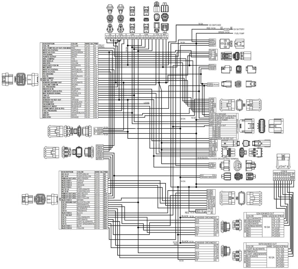
5 Figure 5 5
6 Holley Technical Support 1801 Russellville Road Bowling Green, KY Holley Performance Products, Inc. All rights reserved. 199R11429 Revision Date:
Ford Coyote Non-VVT Main Harness PN
 Ford Coyote Non-VVT Main Harness PN 558-114 This wiring harness interfaces a Holley EFI ECU to a Ford Coyote engine that has had the cam VVT hardware locked out. It is meant to be used in conjunction with
Gen III HEMI Harness PN or
 Gen III HEMI Harness PN 558-106 or 558-107 This wiring harness interfaces a Holley EFI ECU to a Gen III HEMI engine. It is meant to be used in conjunction with an injector harness, a coil harness, and
EFI HARNESS KIT , & Kit Contents: Power Harness : All Kits
 EFI HARNESS KIT 558-500, 558-501 & 558-502 Kit Contents: Main Harness 558-102: Kits 558-500 558-103: Kits 558-501 & 502 Power Harness 558-308: All Kits Injector Harness 558-200: Kits 558-500 & 502 558-201:
LSx Harness Installation. lsxeverything.com #BecauseYouShould
 LSx Harness Installation lsxeverything.com #BecauseYouShould Table of Contents Slide 1 Introduction Page Slide 2 Table of Contents Slide 3 Starting Instructions Slide 4 Power Connections Slide 5 Ground
WIRING MANUAL & DIAGRAMS 199R10555
 WIRING MANUAL & DIAGRAMS 199R10555 HP EFI and Dominator EFI Systems Contents 1.0 Manual Overview... 2 1 1.1 Important Wiring Do s and Don ts... 3 2.0 ECU Installation, Connectors, and Pinout... 3 2.1 Pinout...
MegaSquirt III for Gen 3 HEMI. Hardware Install THE FOLLOWING SENSOR PART NUMBERS APPLY TO ALL HARNESSES FOR ENGINES 2004 TO CURRENT:
 MegaSquirt III for Gen 3 HEMI MegaSquirt controllers are experimental devices intended for educational purposes. MegaSquirt controllers are not for sale or use on pollution controlled vehicles. Check the
This is the layout of a typical harness form a TPI Camaro.
 TPI wiring harness, typical 1986-89: This is the layout of a typical harness form a 1986-88 TPI Camaro. (A) bulkhead conn. through firewall. (B) ecm conn. (C) jct. conn for fuel injectors and cooling fan.
INSTRUCTION MANUAL PLUG AND PLAY EMS KIT
 INSTRUCTION MANUAL PLUG AND PLAY EMS KIT LOTUS ELISE/EXIGE/2-ELEVEN 2004+ with 2ZZ-GE ENGINE DOCUMENT 19-0046 Radium Engineering LLC 2012, All right reserved 1. Introduction 2. Warnings and Cautions 3.
QUICK START GUIDE 199R10546
 QUICK START GUIDE 199R10546 1.0 Overview This contains detailed information on how to use Holley EFI software and perform tuning that is included within the software itself. Once you load the software,
MegaSquirt III for LS Style Engines. Hardware Install. 1. Disconnect and remove the battery from the vehicle.
 MegaSquirt III for LS Style Engines MegaSquirt controllers are experimental devices intended for educational purposes. MegaSquirt controllers are not for sale or use on pollution controlled vehicles. Check
PLUG & PLAY. Quick Start Guide. GM LS 58X Drop On Harness. MS3Pro ULTIMATE
 Quick Start Guide PLUG & PLAY GM LS 58X Drop On Harness MS3Pro ULTIMATE For GM LS Engines with 58X Crank Triggers Thank you for your purchase and support for American made products! We have designed this
Installation Instructions for: EMS P/N Toyota MR2 Turbo Toyota Celica All Trac
 Installation Instructions for: EMS P/N 30-1120 1991-1992 Toyota MR2 Turbo 1990-1992 Toyota Celica All Trac! WARNING: This installation is not for the tuning novice nor the PC illiterate! Use this system
TELORVEK EFI 5.0 Coyote Sequential Fuel Injection System Part # CY-11
 Page #1 TELORVEK EFI 5.0 Coyote Sequential Fuel Injection System Part # CY-11 WIRING INSTRUCTIONS Thank you for purchasing the absolute finest of wiring kits for the Ford Motor Co. Coyote modular engine.
HP and Dominator Component Selection Guide. Use when building Dominator Systems or Custom HP Systems. Step 2 (notes) Choose Your Main Harness
 Choose Your Main Harness") HP and Dominator Component Selection Guide Use when building Dominator Systems or Custom HP Systems Step 1 (required) Choose your ECU & Main Power Harness Step 2 (notes) Choose Your Main Harness Step 3
HP and Dominator Component Selection Guide Use when building Dominator Systems or Custom HP Systems Step 1 (required) Choose your ECU & Main Power Harness Step 2 (notes) Choose Your Main Harness Step 3
Megasquirt EX, Installation Instructions document revision 1.4 (Includes also the version equipped with wasted-spark ignition)
") Megasquirt EX, Installation Instructions document revision 1.4 (Includes also the version equipped with wasted-spark ignition) General Megasquirt EX is a programmable engine control system, based on Megasquirt
Megasquirt EX, Installation Instructions document revision 1.4 (Includes also the version equipped with wasted-spark ignition) General Megasquirt EX is a programmable engine control system, based on Megasquirt
Electromotive Tec GT Installation Supplement for the Porsche
 Electromotive Tec GT Installation Supplement for the Porsche 928 1987-95 Copyright 2009 928 Motorsports, LLC. all rights reserved Toll-Free Tech Hot Line: 877-FOR-928M 877-367-9286 Please do not copy this
Setup Tabs. Basic Setup: Advanced Setup:
 Setup Tabs Basic Setup: Password This option sets a password that MUST be entered to re-enter the system. Note: ProEFI can NOT get you into the calibration if you lose this password. You will have to reflash
DISTRIBUTORLESS IGNITION SYSTEM Installation and Adjustment Instructions
 DISTRIBUTORLESS IGNITION SYSTEM Installation and Adjustment Instructions 1.0 INTRODUCTION: Congratulations on your purchase of a Holley Distributorless Ignition System! Holley cannot and will not be responsible
4. Remove distributor hold-down. Lift the distributor upwards and remove.
 Holley Sniper EFI HyperSpark Distributors are designed to plug and play with Sniper EFI systems. This design includes a single Hall Effect sensor providing crankshaft speed to the ECU. The precision machined
MS3-Pro LSx Drop On Harness
 24x MS3-Pro LSx Drop On Harness For engines with 24X crank triggers Thank you for buying our drop on wiring harness! We have designed this harness to support anything from a stock motor swapped into a
GENERAL MOTORS SERVICE PARTS OPERATION 6200 Grand Pointe Drive, Grand Blanc, MI 48439
 LS IGNITION CONTROLLER 19355418 Ignition Control for Carbureted LS Series Engines (24x Crankshaft Index/1x Camshaft Index, 58x Crankshaft Index/4x Camshaft Index) Parts Included Quantity Ignition Controller
1. Index. LS Wiring Harness. 2. Presentation Warnings and Warranty Terms Overview Labels...7
 OWNER S MANUAL 1. Index 2. Presentation...4 3. Warnings and Warranty Terms...5 4. Overview...6 5. Labels...7 6. Diagrams...7 6.1 FT500/FT500 Aux - Inputs/outputs...7 6.2 Nano WB O2 #1...8 6.3 Nano WB
Lamborghini Huracan Kit
 Lamborghini Huracan Kit Thank you for choosing the Syvecs Huracan kit The kit comes with the following: 1 x Syvecs S12 Ecu 1 x GDI12 Driver 1 x Wiring Loom Installation 1.) Remove the Negative Terminal
Direct Link Basic Tuning Guide (Delphi)
") Direct Link Basic Tuning Guide (Delphi) This Guide is intended to answer basic Direct Link tuning questions and to act as a Quick Start Guide. It is not intended to be the Gospel on the tuning process
Direct Link Basic Tuning Guide (Delphi) This Guide is intended to answer basic Direct Link tuning questions and to act as a Quick Start Guide. It is not intended to be the Gospel on the tuning process
TELORVEK II RJ-32 Big Block RamJet Fuel Injection System
 Page #1 TELORVEK II RJ-32 Big Block RamJet Fuel Injection System This wiring system is compatible with the GM Performance part big block Ramjet 502 engine. The harness is designed to dress up the appearance
HP EFI UNIVERSAL RETROFIT KITS
 HP EFI UNIVERSAL RETROFIT KITS 550-500 (HP Universal Retrofit Kit for 4150 carb style intakes) 550-501 (HP Universal Retrofit Kit for 4500 carb style intakes) INSTALLATION INSTRUCTIONS 199R10510 NOTE:
Installation Guide. Thank you for the purchase of our product. You have just unleashed infinite control, power and ability into your hands.
 Installation Guide Thank you for the purchase of our product. You have just unleashed infinite control, power and ability into your hands. This product is for race use only by experienced engine tuners.
HOLLEY VR2 FUEL PUMPS P/N & Installation Instructions 199R10975
 HOLLEY VR2 FUEL PUMPS P/N 12-3000 & 12-3000-2 Installation Instructions 199R10975 WARNING! THESE INSTRUCTIONS MUST BE READ AND FULLY UNDERSTOOD BEFORE BEGINNING INSTALLATION. FAILURE TO FOLLOW THESE INSTRUCTIONS
INSTALLATION INSTRUCTIONS. Revision 3.1.1
 INSTALLATION INSTRUCTIONS Revision 3.1.1 Table of Contents INTRODUCTION... 4 INSTALLATION OVERVIEW... 5 Included Parts... 6 DEVICE WIRING... 7 Required Parts... 7 Guidelines... 7 Wiring Diagram... 8 Compatible
Timing Input Adapter User Manual
 Timing Input Adapter User Manual 30-3805-05 2 AEM Infinity Harness Manuals Introduction Several universal wiring harness options are available for Infinity products. They range in complexity from simple
Procharger Stage II Intercooled Supercharger System (11-14 GT)
") Procharger Stage II Intercooled Supercharger System (11-14 GT) Installation Time: Approximately one day. Installed on 2012 Mustang GT 5.0/Manual Required Tools 3/8 Socket Set (Standard and Metric) 1/2
Procharger Stage II Intercooled Supercharger System (11-14 GT) Installation Time: Approximately one day. Installed on 2012 Mustang GT 5.0/Manual Required Tools 3/8 Socket Set (Standard and Metric) 1/2
Stratified MegasQuirt Plug and Play ND64
 Stratified MegasQuirt Plug and Play ND64 Generic Plug and Play Electronic Fuel Injection System Installation and User Guide Thank you and congratulations on the purchase of your new Stratified PNP ND64
POLESTAR HS Management System
 POLESTAR HS Management System Installation Instructions This document contains the information needed to install and adjust the POLESTAR HS Engine Management System. It assumes that the system already
Holley EFI 16 Injector Setup (8 Cylinder Engines) Setup of 8 Injectors in 8:2 Amp Peak and Hold Mode
 Setup of 8 Injectors in 8:2 Amp Peak and Hold Mode") Holley EFI 16 Injector Setup (8 Cylinder Engines) Setup of 8 Injectors in 8:2 Amp Peak and Hold Mode TABLE OF CONTENTS: 16 Injector Setup (4 Options)... 1 General Information... 2 16 Injector Option 1...
Holley EFI 16 Injector Setup (8 Cylinder Engines) Setup of 8 Injectors in 8:2 Amp Peak and Hold Mode TABLE OF CONTENTS: 16 Injector Setup (4 Options)... 1 General Information... 2 16 Injector Option 1...
Manual P/N Copyright Third Edition June 21, 2005
 P/N 60212, 60213, 60214 & 60215 1996-99 GM VORTEC WIRE HARNESS INSTALLATION INSTRUCTIONS Manual P/N 90524 Copyright 2003 Third Edition June 21, 2005 PAINLESS PERFORMANCE PRODUCTS 2501 Ludelle Street, Fort
Part Number: Cobra-75
 Ford 5.0 EFI Harness Installation Manual for Wiring Kit U n i v e r s a l F i t Part Number: Cobra-75 Ron Francis Wiring & The Detail Zone 200 Keystone Rd. Chester, PA 19013 877-968-7842 www.ronfrancis.com
R8 / LP560 Kit. Thank you for choosing the Syvecs R8 / LP560 Kit. The kit comes with the following: 1 x Syvecs S12 Ecu. 1 x Wiring Loom.
 R8 / LP560 Kit Thank you for choosing the Syvecs R8 / LP560 Kit The kit comes with the following: 1 x Syvecs S12 Ecu 1 x Wiring Loom Installation 1.) Remove the Negative Terminal from the battery on the
Instruction Manual P/N B Series COP Conversion Kit
 Instruction Manual P/N 30-2860 B Series COP Conversion Kit KIT CONTENTS 1 x 35-2840 IGNITER W/ BRACKET 1 x 30-3255 HONDA EPM 4 x 30-2850 COIL 1 x 35-3860 B SERIES COP HARNESS 1 x 35-3861 EPM HARNESS 2
Syvecs S6 GP. Syvecs Limited. Pinouts and Wiring Info. Ryan Griffiths
 1 Syvecs Limited Syvecs S6 GP Pinouts and Wiring Info Ryan Griffiths 24 10 2011 This document intended for use by a technical audience and describes a number of procedures that are potentially hazardous.
Universal Drop-In Fuel Cell Pump Hangers
 Universal Drop-In Fuel Cell Pump Hangers P/Ns 12-139, 12-140, 12-141, 12-142, 12-143, 12-144, 12-145, 12-146, 12-147, 12-148, 12-149, & 12-155 NOTE: Please read all instructions before proceeding with
Installation Instructions for: EMS P/N Ford Mustang 5.0L
 Installation Instructions for: EMS P/N 30-1400 1986-93 Ford Mustang 5.0L! WARNING: This installation is not for the tuning novice nor the PC illiterate! Use this system with EXTREME caution! The AEM EMS
SUM EFI Wiring Harness for GM LS1 Engine INSTALLATION INSTRUCTIONS
 SUM-890122 EFI Wiring Harness for GM LS1 Engine INSTALLATION INSTRUCTIONS 1 INTRODUCTION This harness is designed for GM 1997-2002 LS1 fuel injected engines utilizing a mechanical throttle body and throttle
Ford Racing 4.6L 3V Crate Engine Control Pack
 Ford Racing 4.6L 3V Crate Engine Control Pack Installation Time: 3-6 hours on a Foxbody Mustang Tools Required: Basic English and Metric Socket and Wrench Set Flat and Phillips Screwdrivers Torx bits Hammer
Table of Contents. 4 Getting Started 4 About the Juice 5 Safety Terms 5 Product Registration 6 Important Notes 7 Truck Orientation
 Table of Contents 4 Getting Started 4 About the Juice 5 Safety Terms 5 Product Registration 6 Important Notes 7 Truck Orientation 8 Juice Installation 1999-2003 (7.3L) 8 Supplied Items & Required Tools
MALLORY FIRESTORM CD MULTI COIL HARDWARE INSTALLATION - PN 69150C / 69150R
 FORM 69150C/R MALLORY FIRESTORM CD MULTI COIL HARDWARE INSTALLATION - PN 69150C / 69150R To ensure you are using the most current instruction sheet, please visit www.malloryfirestorm.com. CAUTION! The
HOWELL INSTALLATION MANUAL. Tuned Port Or LT-1 Fuel Injection Harness ( )
") HOWELL ENGINE DEVELOPMENTS, INC. FUEL INJECTION APPLICATIONS INSTALLATION MANUAL Tuned Port Or LT-1 Fuel Injection Harness (1985-1992) Howell Engine Developments, Inc. 6201 Industrial Way Marine City,
HOWELL ENGINE DEVELOPMENTS, INC. FUEL INJECTION APPLICATIONS INSTALLATION MANUAL Tuned Port Or LT-1 Fuel Injection Harness (1985-1992) Howell Engine Developments, Inc. 6201 Industrial Way Marine City,
Installation Instructions for: EMS P/N Toyota Supra
 Installation Instructions for: EMS P/N 30-1110 1987-1988 Toyota Supra! WARNING: This installation is not for the tuning novice nor the PC illiterate! Use this system with EXTREME caution! The AEM EMS System
Installation Instructions for: EMS P/N Ford Mustang 5.0L
 Installation Instructions for: EMS P/N 30-1401 1994-95 Ford Mustang 5.0L! WARNING: This installation is not for the tuning novice nor the PC illiterate! Use this system with EXTREME caution! The AEM EMS
GENERAL MOTORS SERVICE PARTS OPERATION 6200 Grand Pointe Drive, Grand Blanc, MI 48439
 LS CIRCLE TRACK IGNITION CONTROLLER 19355863 Ignition Control for Carbureted LS Series Engines (24x Crankshaft Index/1x Camshaft Index, 58x Crankshaft Index/4x Camshaft Index) Parts Included Quantity Ignition
Speed-Pro EFI Installation Manual
 Speed-Pro EFI Installation Manual Speed-Pro Electronics Installation Manual Page The wiring harness is labeled on each of the connectors to simplify installation. Your application may not require the use
MALLORY FIRESTORM CD MULTI COIL HARDWARE INSTALLATION - PN 69050S / 69050R
 FORM 69050S/R MALLORY FIRESTORM CD MULTI COIL HARDWARE INSTALLATION - PN 69050S / 69050R To ensure you are using the most current instruction sheet, please visit www.malloryfirestorm.com. CAUTION! The
Layout Diagrams. Section CONTENTS. General Layout Diagram Floor / Roof Engine Compartment Door
 1-1 Section 1 Layout Diagrams CONTENTS General Layout Diagram...1-3 Engine Compartment...1-4 Engine / Transmission...1-6 Floor / Roof...1-16 Door...1-18 Boot Compartment...1-20 Instrument Panel...1-10
Quick Start Guide. This is only a quick start guide. A full wiring and installation manual is included in PCLink.
 Quick Start Guide This is only a quick start guide. A full wiring and installation manual is included in PCLink. Installer I/O Table Wire Description Installer Connection Typical Application +14V Bat Full
2009 Yamaha Apex Snowmobile
 PARTS LIST 2009 Yamaha Apex Snowmobile Installation Instructions quantity description 1 power commander 1 USB cable 1 cd-rom 1 installation guide 2 power commander decals 2 dynojet decals 2 velcro strip
2011 KTM 690 Duke Z-Fi MX Installation Instructions P/N F580
 2011 KTM 690 Duke Z-Fi MX Installation Instructions P/N F580 WARNING! USE ONLY IN RACE OR OTHER CLOSED COURSE APPLICATIONS AND NEVER ON PUBLIC ROADS Parts List: Z-Fi MX Control Unit Fuel Harness Download
MSD 6LS-2 Ignition Controller for Carbureted and EFI LS 2/LS 7 Engines PN 6012
 MSD 6LS-2 Ignition Controller for Carbureted and EFI LS 2/LS 7 Engines PN 6012 ONLINE PRODUCT REGISTRATION: Register your MSD product online. Registering your product will help if there is ever a warranty
TELORVEK III. WIRING INSTRUCTIONS FOR LT-40 LT-1 Fuel Injection System
 TELORVEK III WIRING INSTRUCTIONS FOR LT-40 LT-1 Fuel Injection System Page #1 Thank you for purchasing the absolute finest of wiring kits for the General Motors fuel injection. We have taken considerable
99-00 Civic EK K-Series Swap Conversion Wiring Harness V 4.0 Installation Manual
 99-00 Civic EK K-Series Swap Conversion Wiring Harness V 4.0 Installation Manual This guide walks you through the steps to install your Hybrid Racing K-Series swap conversion harness for 99-00 Civic. Written
Telephone: Fax: VAT Registration No.:
 Telephone: Fax: VAT Registration No.: K143 AC compressor clutch relay X88 AC connector S63 AC refrigerant pressure switch S341 AC refrigerant triple pressure switch A16 Anti-lock braking system (ABS) control
IT S ELECTRIC SWITCHING TO HOLLEY EFI YIELDS BETTER DRIVABILITY AND MORE POWER FOR A BOOSTED 68 FIREBIRD
 WORDS: Scott Parker PICTURES: By Redline Motorsports IT S ELECTRIC SWITCHING TO HOLLEY EFI YIELDS BETTER DRIVABILITY AND MORE POWER FOR A BOOSTED 68 FIREBIRD I t s been said many times, and often it has
Installation Instructions for: EMS P/N Acura Integra Acura 2.3CL Honda Accord Honda Civic
 ! Installation Instructions for: EMS P/N 30-1010 00-01 Acura Integra 98-99 Acura 2.3CL 98-02 Honda Accord 99-00 Honda Civic WARNING: This installation is not for the tuning novice nor the PC illiterate!
Part Number: TDZ-75SD / BRONCO-75SD
 Ford 5.0 EFI Harness Installation Manual For Classic Fords & Mustangs and Early Broncos Part Number: TDZ-75SD / BRONCO-75SD Ron Francis Wiring & The Detail Zone 200 Keystone Rd. Chester, PA 19013 800-292-1940
Honda Civic Type R FK Kit
 Honda Civic Type R FK Kit Thank you for choosing the Syvecs FK kit The kit comes with the following: 1 x Syvecs S6PlusEcu 1 x GDI12 Driver 1 x Wiring Loom Installation 1.) Remove the Negative Terminal
R35GTR SGTR Kit. The kit comes with the following: 1 x Syvecs S6Plus. 1 x SGTR Loom. Installation
 R35GTR SGTR Kit Thank you for choosing the Syvecs SGTR kit The kit comes with the following: 1 x Syvecs S6Plus 1 x SGTR Loom Installation 1.) Remove the Negative Terminal from the battery on the Vehicle
GM EV6 Injector Adapter Harness User Manual
 GM EV6 Injector Adapter Harness User Manual 30-3805-0 THIS PRODUCT IS LEGAL IN CALIFORNIA FOR RACING VEHICLES ONLY AND SHOULD NEVER BE USED ON PUBLIC HIGHWAYS. Introduction Some harness user manuals contain
2-row and All-row systems included.
 Ag Leader Technology Cotton Picker Installation Installation Instructions for John Deere cotton picker models: 2-row and All-row systems included. IMPORTANT: Ensure the model numbers shown above correspond
Installation Instructions for: EMS P/N and U Honda S2000
 Installation Instructions for: EMS P/N 30-1052 and 30-1052U 00-04 Honda S2000! WARNING: This installation is not for the tuning novice nor the PC illiterate! Use this system with EXTREME caution! The AEM
4 BBL THROTTLE BODY FUEL INJECTION MASTER KIT
 4 BBL THROTTLE BODY FUEL INJECTION MASTER KIT 550-405K 950 CFM Polished Aluminum Throttle Body + Complete Fuel System 550-406K 950 CFM Hard Core Gray Throttle Body + Complete Fuel System FUEL INJECTION
MGL Avionics EFIS G2 and iefis
 MGL Avionics EFIS G2 and iefis Guide to using the MGL RDAC CAN interface with the LAD AERO Injection Kit on ROTAX 912-912S General... 3 Data connections... 3 LAD AERO ROTAX 912 engine data from ECU...
JACKAROO TIPS Understanding the MIL fault codes on a Jackaroo Turbo Diesel
 JACKAROO TIPS Understanding the MIL fault codes on a Jackaroo Turbo Diesel The Jackaroo, as with all vehicles intended to be supplied to the USA market, (as the Isuzu Trooper) is fitted with OnBoard Diagnostics
MSD LS-1/LS-6 Controller for Carbureted and EFI Gen III Engines PN 6010
 MSD LS-1/LS-6 Controller for Carbureted and EFI Gen III Engines PN 6010 Parts Included 1 Ignition Controller, PN 6010 1 Pro-Data+ Software CD 1 Harness 1 Parts Bag 6 Timing Modules Optional Accessories
Adaptronic esel002 Select ECU for RX8 Series 1
 1 P a g e Adaptronic esel002 Select ECU for RX8 Series 1 Applicable vehicles / engines: Mazda RX8 series 1 (2003 2008) 1.3L RENESIS 13B-MSP and non-msp engines 2 P a g e Setup / installation procedure
FUEL INJECTION SYSTEM - MULTI-POINT
 FUEL INJECTION SYSTEM - MULTI-POINT 1988 Jeep Cherokee 1988 Electronic Fuel Injection JEEP MULTI-POINT 4.0L Cherokee, Comanche, Wagoneer DESCRIPTION The Multi-Point Electronic Fuel Injection (EFI) system
HOWELL INSTALLATION MANUAL. Throttle Body Fuel Injection Harness
 HOWELL ENGINE DEVELOPMENTS, INC. FUEL INJECTION APPLICATIONS INSTALLATION MANUAL Throttle Body Fuel Injection Harness Howell Engine Developments, Inc. 6201 Industrial Way Marine City, MI 48039 Phone: 810-765-5100
Fuel Metering System Component Description
 1999 Chevrolet/Geo Tahoe - 4WD Fuel Metering System Component Description Purpose The function of the fuel metering system is to deliver the correct amount of fuel to the engine under all operating conditions.
ProECU Mazda MX-5. Live Data Guide 2005-onward Model Year. v1.06
 ProECU Mazda MX-5 Live Data Guide 2005-onward Model Year v1.06 Live Data Live Data Display ProECU Mazda MX-5 can offer real time exceptionally high speed data display and the ability to log this displayed
INSTALLATION GUIDE. Dynojet Research 2191 Mendenhall Drive Suite 105, North Las Vegas NV,
 INSTALLATION GUIDE www.dynojetwb2.com Dynojet Research 2191 Mendenhall Drive Suite 105, North Las Vegas NV, 89081 1-800-992-4993 2008 Dynojet Research, Inc. All Rights Reserved. Wideband 2 Installation
Telephone: Fax: VAT Registration No.:
 Telephone: Fax: VAT Registration No.: Name: Manufacturer: Ford Address: Model: Year: 1994 Registration: Tel - Private: Tel - Business: Mileage: Job number: Terminal side Wire side Component/circuit description
Digifant Ignition Basics, Eurovan Or, what to look for if your 5 Cylinder Eurovan won t start due to no spark
 Digifant Ignition Basics, 1992-96 Eurovan Or, what to look for if your 5 Cylinder Eurovan won t start due to no spark The story: In the spring of 2007, I started to have hard starting issues with my 93
SYTY Trouble Code: ALDL INFORMATION
 SYTY Trouble Code: ALDL INFORMATION A -- Ground G -- Fuel Pump B -- Diagnostic Terminal H -- Brake Sense Speed Input F -- TCC M -- Serial Data (special tool needed - Do Not Use) For ECM Trouble Codes,
Powertrain DTC Summaries EOBD
 Powertrain DTC Summaries Quick Reference Diagnostic Guide Jaguar X-TYPE 2.0 L 2002.25 Model Year Refer to page 2 for important information regarding the use of Powertrain DTC Summaries. Jaguar X-TYPE 2.0
Installation Instructions General Motors 8.1 Sequential Vapor Injection (S.V.I.) System 7500/6500 Series Trucks model year.
 System 7500/6500 Series Trucks model year.") Installation Instructions General Motors 8.1 Sequential Vapor Injection (S.V.I.) System 7500/6500 Series Trucks 2003-2005 model year. Technocarb Equipment (2004) Ltd. 4-30435 Progressive Way Abbotsford,
Installation Instructions General Motors 8.1 Sequential Vapor Injection (S.V.I.) System 7500/6500 Series Trucks 2003-2005 model year. Technocarb Equipment (2004) Ltd. 4-30435 Progressive Way Abbotsford,
Core Harness System Crank/Cam Adapter Harness FAST Dual Sync Distrubutor 35" STOP!
 Instruction Manual 30-3805-20 Core Harness System Crank/Cam Adapter Harness FAST Dual Sync Distrubutor 35" STOP! THIS PRODUCT HAS LEGAL RESTRICTIONS. READ THIS BEFORE INSTALLING/USING! THIS PRODUCT MAY
1. Index. PRO600 Wiring Harness. 2. Presentation Warnings and Warranty Terms Overview PRO600 Harness...6
 OWNER S MANUAL 1. Index 2. Presentation...4 3. Warnings and Warranty Terms...5 4. Overview...6 4.1 PRO600 Harness...6 5. Versions and components...7 5.1 PRO600 components...7 6. Labels...8 7. Diagrams...9
Instructions for 2-row monitoring only
 Installation Instructions for CaseIH cotton picker models: Instructions for 2-row monitoring only CAUTION: Ensure the model numbers shown above correspond to the machine model. If you receive the incorrect
Installation Instructions for: EMS P/N Toyota Supra
 Installation Instructions for: EMS P/N 30-1130 1989-1992 Toyota Supra! WARNING: This installation is not for the tuning novice nor the PC illiterate! Use this system with EXTREME caution! The AEM EMS System
G - TESTS W/CODES - 2.2L
 G - TESTS W/CODES - 2.2L 1994 Toyota Celica 1994 ENGINE PERFORMANCE Toyota 2.2L Self-Diagnostics Celica INTRODUCTION If no faults were found while performing F - BASIC TESTING, proceed with self-diagnostics.
AMS F1-I INTAKE MANIFOLD
 AMS F1-I INTAKE MANIFOLD The goal of AMS is to provide the highest quality, best performing products available. By utilizing research and development, and rigorous testing programs AMS will never compromise
SimMotor User Manual Small Engine Simulator and HIL V COPY RIGHTS ECOTRONS LLC All rights reserved
 V2.3.1 SimMotor User Manual Small Engine Simulator and HIL V2.3.1 COPY RIGHTS ECOTRONS LLC All rights reserved Http://www.ecotrons.com Table of Contents Read before you start:...1 Why do I need SimMotor?...2
2011 Yamaha Apex Snowmobile
 PARTS LIST 2011 Yamaha Apex Snowmobile Installation Instructions quantity description 1 power commander 1 USB cable 1 cd-rom 1 installation guide 2 power commander decals 2 dynojet decals 2 velcro strip
I N S T A L L A T I O N I N S T R U C T I O N S TIMING COMMANDER Interface Gauge Ver 7
 I N S T A L L A T I O N I N S T R U C T I O N S 103033 TIMING COMMANDER Interface Gauge Ver 7 This product is designed to interface with the airtemp (IAT) sensor in your vehicle AND your tuner software
Polaris Axys Sidekick Installation Instructions
 2016-2017 Polaris Axys Sidekick Installation Instructions 1. Remove hood and side panels. 2. Remove fasteners and slide console back. 3. Remove belt and driven clutch. 4. Remove clutch cover/ oil-tank
C FORD F250 / F L POWERSTROKE DIESEL WITH AUTOMATIC TRANSMISSIONS ONLY
 EXHAUST BRAKES C40019 1999-2003 FORD F250 / F350 7.3L POWERSTROKE DIESEL WITH AUTOMATIC TRANSMISSIONS ONLY Getting Started Thank you and congratulations on your purchase of a Pacbrake exhaust retarder.
About the Instructions:
 About the Instructions: The Mass Air Modifier is very easy to install and configure. The print instructions and YouTube videos are very detailed on purpose. This detail is intended to provide you with
Ducati Monster Ducati Monster 796 (Euro Spec Only) Z-Fi QS Installation Instructions P/N S192S, S192R
 Z-Fi QS Installation Instructions P/N S192S, S192R") 2009-2011 Ducati Monster 696 2010-2012 Ducati Monster 796 (Euro Spec Only) Z-Fi QS Installation Instructions P/N S192S, S192R WARNING! USE ONLY IN RACE OR OTHER CLOSED COURSE APPLICATIONS AND NEVER ON
2009-2011 Ducati Monster 696 2010-2012 Ducati Monster 796 (Euro Spec Only) Z-Fi QS Installation Instructions P/N S192S, S192R WARNING! USE ONLY IN RACE OR OTHER CLOSED COURSE APPLICATIONS AND NEVER ON
4.0L CEC SYSTEM Jeep Cherokee DESCRIPTION OPERATION FUEL CONTROL DATA SENSORS & SWITCHES
 4.0L CEC SYSTEM 1988 Jeep Cherokee 1988 COMPUTERIZED ENGINE Controls ENGINE CONTROL SYSTEM JEEP 4.0L MPFI 6-CYLINDER Cherokee, Comanche & Wagoneer DESCRIPTION The 4.0L engine control system controls engine
This product is legal in California for racing vehicles only and should never be used on public highways.
 Installation Instructions for: EMS P/N 30-1602 and 30-1602U 96-99 Nissan 180SX SR20DET 97-98 Nissan Silvia S14 SR20DET 93-98 Nissan Silvia S14 SR20DET (Europe) 99-02 Nissan Silvia S15 SR20DET! WARNING:
WARNING! USE ONLY IN RACE OR OTHER CLOSED COURSE APPLICATIONS AND NEVER ON PUBLIC ROADS
 2009-2010 Aprilia RSV4/FACTORY Z-Fi TC / Z-FI QS INSTALLATION INSTRUCTIONS P/N s S940S, S940R, T940S, T940R WARNING! USE ONLY IN RACE OR OTHER CLOSED COURSE APPLICATIONS AND NEVER ON PUBLIC ROADS Z-Fi
COBB TUNING. AccessTUNER. USDM Mitsubishi Table Descriptions and Tuning Tips. Copyright 2008 Cobb Tuning Products, LLC. All Rights Reserved. P.
 COBB TUNING AccessTUNER TM USDM Mitsubishi Table Descriptions and P.1 Note: This is a list of tables available on all Mitsubishi AccessTUNER products. Not all tables are available in your software. Boost
2 Wire PW Idle Adapter User Manual
 2 Wire PW Idle Adapter User Manual 30-3805-08 2 AEM Infinity Harness Manuals Introduction Several universal wiring harness options are available for Infinity products. They range in complexity from simple