1. Index. LS Wiring Harness. 2. Presentation Warnings and Warranty Terms Overview Labels...7
|
|
|
- Morgan Stafford
- 5 years ago
- Views:
Transcription


1 OWNER S MANUAL
2
3 1. Index 2. Presentation Warnings and Warranty Terms Overview Labels Diagrams FT500/FT500 Aux - Inputs/outputs Nano WB O2 # Nano WB O2 # INJECTOR female Connectors Relay and Fuses Crank Trigger and Cam Sync sensor TPS H2O and Air Temperature Oil and Fuel Pressure Injectors Extra Connectors Electronic throttle body (Drive-by-wire) Signal Outputs to stock ECU Injectors Connectors Coils connectors Standard Sensors Fuel and Oil Pressure Intake Air Temperature Engine Temperature Bosch LSU 4.2 Wideband O2 Sensor NTK Wideband O2 Sensor (for alcohol engines) O2 Reading FuelTech WB-O2 Nano Alcohol O2 (for alcohol engines) Peak and Hold - External Injector Driver Troubleshooting FuelTech Latest Manuals and Software
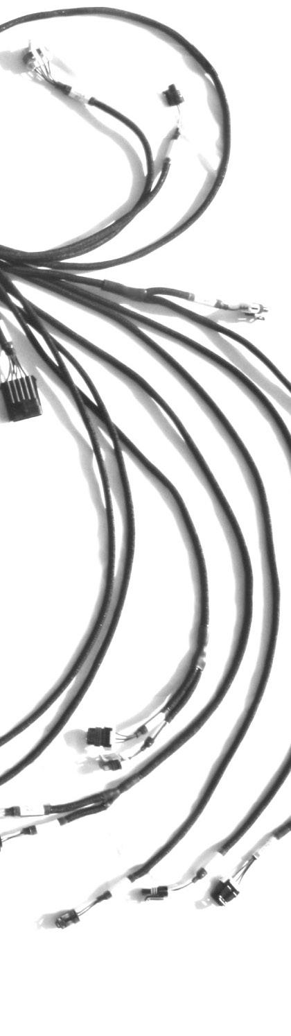
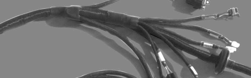
4 2. Presentation The FuelTech is the proper link between the FuelTech FT500 ECU and all of your sensors and actuators. The harness has all the components needed to make a plug and play installation on an engine. It has all the relays and fuses needed for the system on a standard setup, a firewall grommet to hold and seal the harness and every connector has its own label. The insulation and connectors are humidity, heat and oil resistant. Specifications: - 8 injector outputs (EV1 (Jetronic/Minitimer) or EV6/EV14 (USCAR) or Nippon Denso) - Dual FuelTech WB-Nano O2 ready (adapter to Alcohol O2 is sold separately for alcohol engines) - Dual Bosch wideband O2 sensor ready (adapter to NTK lab sensor is sold separately for alcohol engines) - GM Style intake air temperature sensor ready - GM Style engine temperature sensor ready - 2 pressure sensor ready for fuel and oil 0-5V sensor (FuelTech PS150 connector) - 3x high output relays with fuses - Extra connector with 7 inputs and 8 outputs for generic use - Coil outputs: harness is setup for OEM coil harness (re-use your factory harness using stock plug) - Coils are setup in WASTED SPARK mode - 2 FuelTech Peak and Hold external drivers ready - Grommet for firewall Dimensions (in package): 14 x 11 x 14 Weight for LS HARNESS: 8 lbs 3oz - Plugs for both 58x and 24x crank triggers (only one is used) - 24x sensor connector: Delphi Metri-pack x sensor connector: Delphi Metri-pack Plugs for both front and rear cam sync sensors (only one is used) - *** TIMING GEAR MUST BE SINGLE TOOTH ON 24X APPLICATIONS AND FOR SEQUENTIAL TIMING ON 58X APPLICATIONS. USE LS2 STYLE GEAR: PN Front cam sensor: AC Delco Rear cam sensor: AC Delco x sensor connector: Delphi Metri-pack Connectors for stock electronic throttle body (88mm to 90mm) and pedal (drive by wire) and cable throttle (GM TPS round 3-wire plug) - PEDAL: 2005 to 2013 Corvette style - GM THROTTLE - LS2 90mm - GM LS7 90mm - GM LSA/LS9 88mm - GM
5 3. Warnings and Warranty Terms The use of this equipment implies in total accordance with the terms described in this manual and exempts the manufacturer from any responsibility regarding to product misuse. Read all the information in this manual before starting the product installation. This product must be installed and tuned by specialized auto shops and/or personnel with experience on engine tuning. Limited Warranty All products manufactured by FUELTECH are warranted to be free from defects in material and workmanship for one year following the date of original purchase. Warranty claim must be made by original owner with proof of purchase from an authorized reseller. This warranty does not include sensors or other products that FUELTECH carries but did not manufacture. If a product is found defective, such products will, at FUELTECH s option, be replaced or repaired at no cost. All products alleged by Purchaser to be defective must be returned to FUELTECH, postage prepaid, within the one year warranty period. Before starting any electrical installation, disconnect the battery. The inobservance of any of the warnings or precautions described in this manual might cause engine damage and lead to the invalidation of this products warranty. The improper adjustment of the product might cause engine damage. This product does not have a certification for the use on aircrafts or any flying vehicles, as it was not designed for such use or purpose. In some countries where an annual inspection of vehicles is enforced, no modification in the OEM ECU is permitted. Be informed about local laws and regulations prior to the product installation. This limited warranty does not cover labor or other costs or expenses incidental to the repair and/or replacement of products or parts. This limited warranty does not apply to any product which has been subject to misuse, mishandling, misapplication, neglect (including but not limited to improper maintenance), accident, improper installation, tampered seal, modification (including but not limited to use of unauthorized parts or attachments), or adjustment or repair performed by anyone other than FUELTECH. The parties hereto expressly agree that the purchaser s sole and exclusive remedy against FUELTECH shall be for the repair or replacement of the defective product as provided in this limited warranty. This exclusive remedy shall not be deemed to have failed of its essential purpose so long as FUELTECH is willing and able to repair or replace defective goods. FUELTECH reserves the right to request additional information such as, but not limited to, tune up and log files in order to evaluate a claim. Seal violation voids warranty and renders loss of access to update releases. Manual version 1.0 June/2017 5


, relays and fuses.")


 and power ground MUST BE CONNECTED to the battery s negative terminal.")


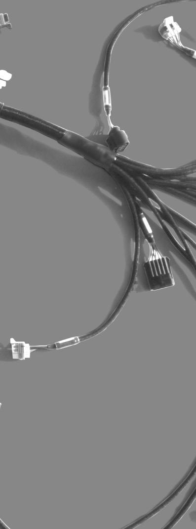
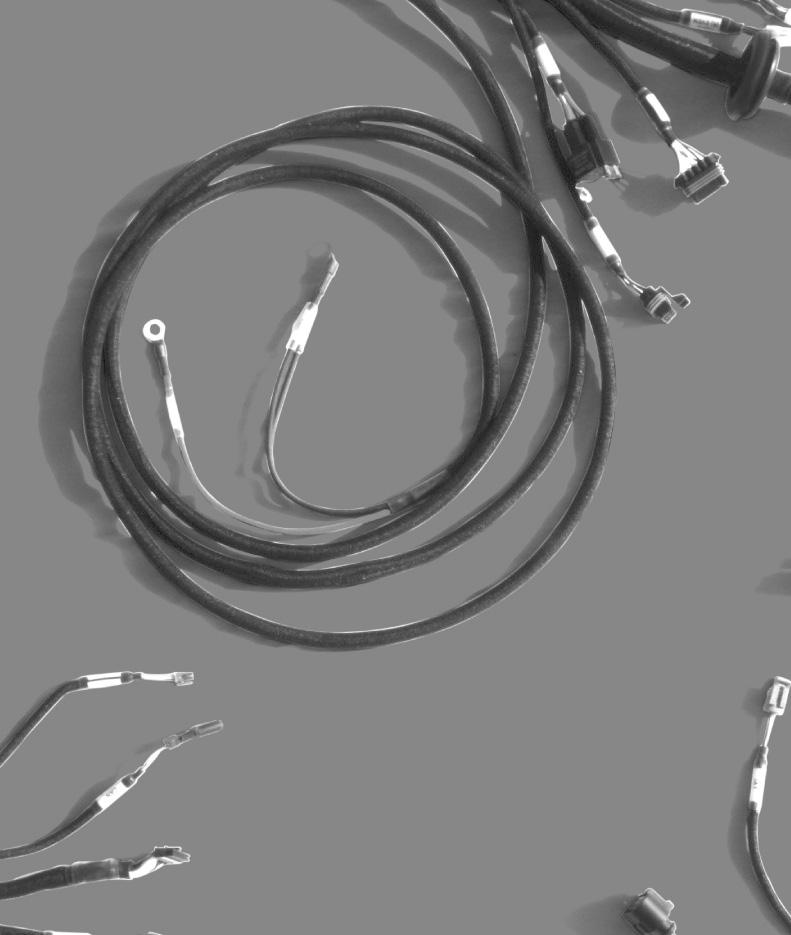
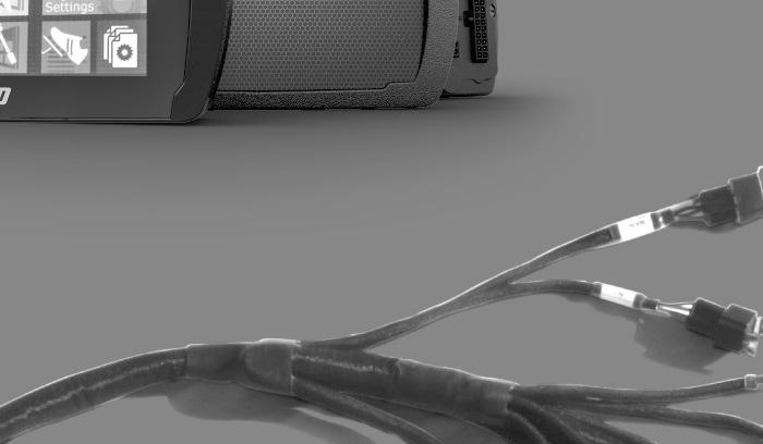
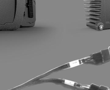
6 4. Overview The FuelTech is a complete plug n' play wiring solution to be used with a FuelTech FT500 ECU. It is designed for systems with 8 staged injectors, 8 individual smart coils and FuelTech Dual Nano O2 to run sequential, semi-sequential or multipoint injection. It is already wired for 2 FuelTech Peak and Hold drivers for setups utilizing low impedance injectors. When using high impedance injectors, Peak and Holds are not needed. In this case a jumper harness (sold separately) is required. The harness is a single piece with a rubber grommet. You will fi nd the connections to all the units, the wires for power supply (+12V to battery, ground and power ground to battery and switched +12V input), relays and fuses. Check below to see all of the connectors and where they are connected: - FuelTech FT500 main and auxiliary: Direct connection to FT500, both connectors must be securely installed. - CAN A: Plugged in the 4way connector in the back of the ECU in order to allow CAN communication with the Wideband Nano and other CAN products. - 2x FuelTech Peak and Hold: These are the driver boxes needed to fi re low impedance injectors. When the system uses high impedance injectors, two jumper harnesses are required (sold separately). If the Peak and Hold or the jumper wires are not being used, the injectors will not fi re. - FuelTech Dual WB-O2 Nano: This connector goes to the FuelTech WB-O2 Nano unit. On the engine side, there is a connector for the O2 sensor. - Switched +12V wire: This wire goes to the ignition switch and it turns all the relays on. - Power ground, battery ground and battery positive: These wires are the system power supply and must be connected exactly as the following: Battery (+) goes straight to the battery s positive or kill switch. Battery (-) and power ground MUST BE CONNECTED to the battery s negative terminal. - Throttle position sensor: The TPS measures the throttle position. The LS harness has a 3-way Metri-Pack connector and almost any 0-5V TPS can be used. - Fuel pressure sensor: This input can be used to read fuel pressure using a FuelTech PS sensor or SSI P51 Packard sensor. - Oil pressure sensor: This input can be used to read oil pressure using a FuelTech PS sensor or SSI P51 Packard sensor. - Crank trigger sensor (Hall effect): LS harness is ready for both 58x and 24x OEM Hall Effect sensors. - Cam sync sensor (Hall effect): LS Harness is ready for both front and rear cam sync OEM Hall Effect sensors MUST BE SINGLE TOOTH ON 24X APPLICATIONS AND FOR SEQUENTIAL INJECTION ON 58X APPLICATIONS (USE CAM GEAR # ). - Engine temperature sensor: Ready for GM style CLT sensor. - Intake air temperature sensor: Ready for GM style IAT sensor. - 2x Bosch wideband sensors; - 3x 40A Relay: The system has 3 relays to power everything. The Main Relay powers the ECU, WB-O2 Nano and all the sensors. There s a second relay that powers the peak and hold drivers and the injectors. Also, there s a third relay that powers the coils. - 8x fuel injectors outputs: 8 injectors outputs (EV1 connector) which allows sequential fuel injection and individual fuel cylinder trim. 6
7 5. Labels All connectors have proper labels to identify each one. It is labeled by color and description name. The colors are related to its functions: Green The green labels are related to the RPM sensors (Crank Trigger and Cam Sync); Yellow Input sensors such as TPS, Engine Temp, Air temp, Fuel Pressure, Oil Pressure, Back Pressure or any other 0-5V sensor, CAN port; Blue Exclusively to O2 sensors (NTK or Bosch); White FT500 Aux connector, Nano connector, Extra Outputs, Extra Inputs, Signals outputs to stock ECU and coils connectors; Purple Peak and Hold and fuel injectors (Primary bank); Black FT500, Main connector, Battery (-), Power Ground; Red Battery (+), Main and Injectors relays/fuses, 12V switch; 6. Diagrams 6.1 FT500/FT500 Aux - Inputs/outputs From To Connector Pin Wire color Connector Pin Function FT Blue #1 PH odd cyl 5 Primary #1 injector FT Blue #2 PH even cyl 5 Primary #2 injector FT Blue #3 PH odd cyl 4 Primary #3 injector FT500 Aux 6 Blue #4 PH even cyl 4 Primary #4 injector FT500 Aux 8 Blue #5 PH odd cyl 2 Primary #5 injector FT500 2 Blue #6 PH even cyl 2 Primary #6 injector FT500 4 Blue #7 PH odd cyl 1 Primary #7 injector FT500 6 Blue #8 PH even cyl 1 Primary #8 injector FT500 Aux 1 White #1 Auxiliary E accelerator / A EXTRA inputs GPI W#1 FT500 Aux 5 White #2 Auxiliary B EXTRA inputs GPI W#2 FT500 Aux 7 White #3 Auxiliary B accelerator / C EXTRA inputs GPI W#3 FT500 9 White #4 Main C oil Oil pressure input FT500 7 White #5 Main B H2O Engine temperature input FT500 5 White #6 Main C fuel / F EXTRA inputs Fuel pressure input FT500 3 White #7 Main B IAT Air temperature input FT500 Aux 12 White #8 Auxiliary H EXTRA inputs GPI W#8 FT500 Aux 10 White #9 Auxiliary J EXTRA inputs GPI W#9 FT500 Aux 3 White #10 Auxiliary D throttle body / K EXTRA inputs GPI W#10 FT White #11 Main C TPS / F throttle body TPS input FT Gray #1 Main G coils odd / F coils even Coils #1 and #6 FT Gray #2 Main C coils odd / G coils even Coils #5 and #8 FT Gray #3 Main B coils odd / C coils even Coils #7 and #4 FT Gray #4 Main F coils odd / B coils even Coils #3 and #2 FT Gray #5 Main A EXTRA outputs GPO G#5 FT500 Aux 2 Gray #6 Auxiliary B EXTRA outputs GPO G#6 FT500 Aux 4 Gray #7 Auxiliary C EXTRA outputs GPO G#7 FT500 1 Gray #8 Main D EXTRA outputs GPO G#8 FT500 Aux 13 Yellow #1 Auxiliary H EXTRA outputs GPO Y#1 FT500 Aux 14 Yellow #2 Auxiliary G EXTRA outputs GPO Y#2 FT500 Aux 15 Yellow #3 Auxiliary B throttle body / F EXTRA outputs GPO Y#3 FT500 Aux 16 Yellow #4 Auxiliary A throttle body / E EXTRA outputs GPO Y#4 7
8 6.2 Nano WB O2 #1 From To Connector Pin Wire color Connector Pin Function Nano WB O2 #1 1 Red O2 Sensor left 6 IP+ Nano WB O2 #1 2 Yellow O2 Sensor left 5 VS- Nano WB O2 #1 3 Brown O2 Sensor left 1 VS+ Nano WB O2 #1 4 Red Main relay 87 Switched +12V from relay Nano WB O2 #1 5 Yellow/Red - - Nano WB O2 #1 6 White/Red CAN male/female 4 CAN HI Nano WB O2 #1 7 Orange O2 Sensor left 2 IA Nano WB O2 #1 8 Green O2 Sensor left 3 H+ Nano WB O2 #1 9 Blue O2 Sensor left 4 H- Nano WB O2 #1 10 Black/White Power ground - Power ground Nano WB O2 #1 11 Black Signal ground - Signal ground Nano WB O2 #1 12 Yellow/Blue CAN male/female 3 CAN LO 6.3 Nano WB O2 #2 From To Connector Pin Wire color Connector Pin Function Nano WB O2 #2 1 Red O2 Sensor right 6 IP+ Nano WB O2 #2 2 Yellow O2 Sensor right 5 VS- Nano WB O2 #2 3 Brown O2 Sensor right 1 VS+ Nano WB O2 #2 4 Red Relay 87 Switched +12V from relay Nano WB O2 #2 5 Yellow/Red - - Nano WB O2 #2 6 White/Red CAN male/female 4 CAN HI Nano WB O2 #2 7 Orange O2 Sensor right 2 IA Nano WB O2 #2 8 Green O2 Sensor right 3 H+ Nano WB O2 #2 9 Blue O2 Sensor right 4 H- Nano WB O2 #2 10 Black/White Power ground - Power ground Nano WB O2 #2 11 Black Signal ground - Signal ground Nano WB O2 #2 12 Yellow/Blue CAN male/female 3 CAN LO 6.4 INJECTOR female From To Connector Pin Wire color Connector Pin Function Injector female A Purple PH odd cyl 10 Injector #1 Injector female B Purple PH even cyl 10 Injector #2 Injector female C Purple PH odd cyl 9 Injector #3 Injector female D Purple PH even cyl 9 Injector #4 Injector female E Purple PH odd cyl 7 Injector #5 Injector female F Purple PH even cyl 7 Injector #6 Injector female G Purple PH odd cyl 6 Injector #7 Injector female H Purple PH even cyl 6 Injector #8 Injector female J Red PH odd/even cyl 3 Switched +12V from relay Injector female K Red PH odd/even cyl 3 Switched +12V from relay 8


; - Pin C: signal output (white). 7.")
9 7. Connectors 7.1 Relay and Fuses All relays available in the LS Harness are fuse protected. Their max current is 30A followed by a 30A fuse. There is a main relay for the FuelTech units such as ECU, O2 conditioner, one relay for the injectors and another relay for the coils. Crank Trigger OEM crank trigger should be plug and play. There are two 3-way Metri- Pack 150. For 24X: # and 58X: # Sensor Sensor pin/wire Harness wire Red wire from 2-core A shielded cable 24X and 58X B Battery s negative C Switched 12V Cam Sync sensor OEM cam sync sensor should be plug and play. The connector is a 3-way Metri-Pack 150 # Crank Trigger and Cam Sync sensor The LS harness is ready to run on OEM 58x or 24x hall effect sensor crank trigger and OEM front and rear cam sync sensors. Sensor Sensor Pin/Wire Harness wire A Switched 12V B Battery s negative Front cam sync sensor Rear cam sync sensor 7.3 TPS C A B C Black wire from 1-core shielded cable Black wire from 1-core shielded cable Battery s negative Switched 12V TPS is a potentiometer that informs the throttle position. FT500 can read almost any 0-5V TPS. The LS harness uses a 3-way Metri-pack Pin A: 5V Supply (green/red); - Pin B: signal ground (black); - Pin C: signal output (white). 7.4 H2O and Air Temperature The has 2 temperature inputs. One input is for the engine temperature (H2O) and the other is for the intake air temperature (AIR). Both sensors are GM style and uses Metri-Pack connectors. - Pin A: signal output; - Pin B: battery s negative. H2O Air 9

; - Pin B: 5V supply (green/red); - Pin C: signal")


 and the other has 7 generic inputs")


10 7.5 Oil and Fuel Pressure The oil and fuel pressure sensor connector are designed for the PS- 150, PS-300 and PS-1500 sensors; ranging from 150 to 1500 psi, with a Packard style 3-way connector. It has a 5V ground and signal. - Pin A: battery s negative (black); - Pin B: 5V supply (green/red); - Pin C: signal output (white). Extra Outputs Pinout Pin FT500 Outputs Function/Sensor A Gray #5 B Gray #6 C Gray #7 D Gray #8 E Yellow #4 F Yellow #3 G Yellow #2 H Yellow #1 7.6 Injectors The LS harness has 8 injector outputs available in 1 bank with three different connectors options: EV1 (Jetronic/Minitimer), EV6/EV14 (USCAR), and Nippon Denso. It also features the OEM sub-harness connector, in case you want to re-use the existing sub-harness. Extra Inputs Pinout Pin FT500 Outputs Function/Sensor A White #1 B White #2 C White #3 D Signal ground E 5V supply F White #6 G Switched +12V H White #8 J White #9 K White # Extra Connectors There are two extra connectors with all the unused inputs and outputs. One of them features 8 outputs (4 yellow and 4 gray) and the other has 7 generic inputs (white color), a 5v output, a switched +12V and a signal ground. Yellow outputs are HALF BRIDGE or PUSH PULL type outputs. This means that they can feed 5A both by negative or positive side. They are important and necessary to control Electronic drive-by-wire throttle (DC motors) and stepper motor 4 wire idle control valves. They also can be used to control any type of LO SIDE or HI SIDE actuator (LO SIDE means the ECU will switch ground to activate the device, HI SIDE means the ECU will switch 12V to active the device). Since it can feed 12V power at 5A, if wired to a relay activating it by ground (from the FuelTech) when turned off, it senses the 12V through the relay coil and feeds back power to the ECU. In this case, it is necessary to run a diode in series (1N4004 or 1N4007) like the following schematic to avoid this issue. 10


 The LS")


11 Both ways of wiring this output are described in the following diagrams: LS2 90mm - GM # LS7 90mm - GM # There are some relays with a built-in diode, like Hella Electronic throttle body (Drive-by-wire) The LS harness also has plug and play connections for the OEM electronic throttle body and pedal. The connections are: LSA/LS9 88mm - GM # Pedal 2005 to 2013 Corvette Style GM Electronic throttle body A Motor 1 Yellow #4 B Motor 2 Yellow #3 C 5V supply Green/red D TPS #2 White #10 E Signal ground Black F TPS #1 White # Signal Outputs to stock ECU The LS Harness has a output connector that shares the signal from the sensors between the FT500 and the stock ECU, the mating connector to wire to the stock ECU is sold separately. Electronic pedal A Signal ground Black B Pedal #1 White #3 C 5V supply Green/red D 5V supply Green/red E Pedal #2 White #1 F Signal ground Black 11


 and odd (Left Driver side) which must be connected")


 It can be purchased Online at www.fueltech.")
.")


12 Pin A B C D E F Outputs Pedal1 Pedal2 Coolant Temp Oil Pressure Camshaft signal Crank signal 7.10 Injectors Connectors The LS Harness has a 10 way Injector sub-connector that will connected to the injector sub-harness (EV1/EV6/Denso) and then plugged to the injectors itself Coils connectors There are 2 coils connectors, even (Right) and odd (Left Driver side) which must be connected to the stock coil harness of the engine. NOTE: When temperature sensors are shared, the voltage pull-up on the FuelTech ECU must be disabled. 8. Standard Sensors 8.1 Fuel and Oil Pressure FuelTech PS-150/300/1500 is a high precision sensor responsible for general pressure readings (fuel, oil, boost, exhaust back pressure, etc.) It can be purchased Online at or from an authorized FuelTech dealer (check the website to locate the dealer nearest to you). FuelTech PS-150/300/1500 sensor below: 8.2 Intake Air Temperature With this sensor, the ECU can monitor the intake air temperature and perform real time compensations. One of its pins is connected to the battery negative, the other to the white #7 wire. Part numbers: FuelTech or GM Connection: 1/8-27NPT - Pressure Range: 0 to 150/300/1500psi - Power Voltage: 5V - Output Scale: V - Electric Connector: 3-way Metri-pack Pin A: Battery s Negative - Pin B: 5V supply - Pin C: Output signal FuelTech part numbers: psi sensor psi sensor psi sensor 8.3 Engine Temperature This sensor is very important for a good running engine, as varying engine temperatures dramatically affect an engine s fuel and timing requirements. On water cooled engines, place this sensor near the engine head, reading the water temperature. On air cooled engines, install this sensor reading the engine oil temperature. One of its pins is connected to the battery negative, the other to the white #5 wire. Part numbers: FuelTech or GM


13 8.4 Bosch LSU 4.2 Wideband O2 Sensor Bosch LSU 4.2 is a pretty popular wideband O2 sensor used with the WB-O2 Nano. 8.5 NTK Wideband O2 Sensor (for alcohol engines) The NTK laboratory wideband O2 sensor is recommended for engines running alcohol. Part numbers: FuelTech or Bosch This sensor must be used with the FuelTech Alcohol O2 module. Adapters for both sensors and WB-O2 unit will be required (sold separately) NTK sensor requires free-air calibration. Check Alcohol O2 manual for further instructions. To purchase NTK sensor, contact FuelTech Part number # O2 Reading 9.1 FuelTech WB-O2 Nano There are dual FuelTech WB-O2 Nano connectors built into the harness. Each WB-O2 Nano has one connector with 12-way Molex MX120G connector. FuelTech WB-O2 Nano does not require free-air calibration. For further information, check FuelTech WB-O2 Nano manual. 9.2 Alcohol O2 (for alcohol engines) FuelTech offers a special conditioner for engines running alcohol, the FuelTech Alcohol O2. A simple adapter harness makes this unit plug and play on the WB-O2 Nano connections. A special NTK laboratory sensor is required by the Alcohol O2. Contact FuelTech in order to purchase the sensors and adapters to plug on the FuelTech LS harness. 13

14 10. Peak and Hold - External Injector Driver Peak and Hold drivers are designed to control the current on low impedance injectors and they are not needed when using high impedance injectors. The FuelTech Peak and Hold has 4 outputs and in the LS Wiring Harness will run one injector per channel. There are 3 different versions of Peak and Hold available to fire different injectors, according to the resistance of the injector. The only differences between the versions are the peak current and the hold current. Some earlier Moran injectors require a 4A/1A driver. Contact FuelTech tech support to confirm correct Peak and Hold drivers before purchasing. When using high impedance injectors without Peak and Hold drivers, jumpers wires (sold separately, part number ) must be connected to the Peak and Hold plugs in the harness. If the jumper wires are not being used then the injectors won t fire since there will be no continuity between the FT500 and injectors. Considering one injector per channel application: 2A/0.5A Bosch 1600cc, Ford Racing 1600cc 4A/1A Siemens Deka 225lb/h, Precision 225lb/h 8A/2A Precision 550lb/h, Billet Atomizer, Moran 11. Troubleshooting Issue FT500 Unit doesn t turn on FT500 doesn t read cranking FT500 reads RPM but engine doesn t start Engine runs but doesn t idle Engine spits & sputters ECU won t communicate to PC Solution 1. Check battery voltage 2. Check power and ground cables 3. Check Switched 12V cable 4. Check ECU harness cables 1. Check crank trigger and cam sync connections 2. Check sensor gap 3. Check diagnostic panel for RPM signal 1. Check if there is spark and injector pulse 2. Check fuel pressure 3. Check crank trigger alignment and TPS calibration 4. Check if outputs are activated and properly configured 5. Check the O2 sensor reading 1. Check TPS calibration 2. Check timing with a timing light 3. Check TPS idle table and adjustment 4. Check O2 sensor reading 1. Check O2 sensor reading 2. Check ignition calibration and firing order 1. Ensure your software version is compatible with your FT500 firmware version 2. Check if read and write buttons get colored when FT500 is connected 12. FuelTech Latest Manuals and Software You can access all updated manuals and software at the FuelTech website:
15

16 455 Wilbanks Dr. Ball Ground, GA, 30107, USA Phone: Toll Free: FuelTechUSA POWER FT ECU
1. Index. PRO600 Wiring Harness. 2. Presentation Warnings and Warranty Terms Overview PRO600 Harness...6
 OWNER S MANUAL 1. Index 2. Presentation...4 3. Warnings and Warranty Terms...5 4. Overview...6 4.1 PRO600 Harness...6 5. Versions and components...7 5.1 PRO600 components...7 6. Labels...8 7. Diagrams...9
MaxxECU quickstart guide ( )
") Be a tuning mastermind. Like us. MaxxECU quickstart guide (2019-02-01) Online help! maxxecu.com/support Wiring diagrams Installation help Pinout Support maxxecu.com/support Legal disclaimer All performance
Be a tuning mastermind. Like us. MaxxECU quickstart guide (2019-02-01) Online help! maxxecu.com/support Wiring diagrams Installation help Pinout Support maxxecu.com/support Legal disclaimer All performance
Manual de Instalação e Operação Installation and Operation Guide Manual de Instalación y Especificaciones Técnicas
 capa Condicionador para Sensor Lambda Banda Larga Wideband Lambda Sensor Conditioner Condicionador para Sensor Lambda de Banda Ancha Manual de Instalação e Operação Installation and Operation Guide Manual
6 channel Datalogger with WB-O2 buit-in signal conditioner Installation and Operation Guide
 6 channel Datalogger with WB-O2 buit-in signal conditioner Installation and Operation Guide Summary 1 Presentation... 4 2 Warnings and Warranty Terms... 5 3 WB-O2 Datalogger Electric Installation... 6
Core Harness System Crank/Cam Adapter Harness FAST Dual Sync Distrubutor 35" STOP!
 Instruction Manual 30-3805-20 Core Harness System Crank/Cam Adapter Harness FAST Dual Sync Distrubutor 35" STOP! THIS PRODUCT HAS LEGAL RESTRICTIONS. READ THIS BEFORE INSTALLING/USING! THIS PRODUCT MAY
ELITE 1000/1500 Dodge SRT QUICK START GUIDE HT
 E N G I N E M A N A G E M E N T S Y S T E M S ELITE 1000/1500 Dodge SRT4 03-05 QUICK START GUIDE HT-140940 LIMITED WARRANTY Lockin Pty Ltd trading as Haltech warrants the HaltechTM Programmable Fuel Injection
EFI HARNESS KIT , & Kit Contents: Power Harness : All Kits
 EFI HARNESS KIT 558-500, 558-501 & 558-502 Kit Contents: Main Harness 558-102: Kits 558-500 558-103: Kits 558-501 & 502 Power Harness 558-308: All Kits Injector Harness 558-200: Kits 558-500 & 502 558-201:
GM Stepper Idle Adapter User Manual
 GM Stepper Idle Adapter User Manual 30-3805-07 THIS PRODUCT IS LEGAL IN CALIFORNIA FOR RACING VEHICLES ONLY AND SHOULD NEVER BE USED ON PUBLIC HIGHWAYS. AEM Performance Electronics AEM Performance Electronics,
GM Throttle Body Adapter Harness User Manual
 GM Throttle Body Adapter Harness User Manual 30-3809-01 THIS PRODUCT IS LEGAL IN CALIFORNIA FOR RACING VEHICLES ONLY AND SHOULD NEVER BE USED ON PUBLIC HIGHWAYS. AEM Performance Electronics AEM Performance
Ford EV6 Injector Adapter Harness User Manual
 Ford EV6 Injector Adapter Harness User Manual 30-3805- THIS PRODUCT IS LEGAL IN CALIFORNIA FOR RACING VEHICLES ONLY AND SHOULD NEVER BE USED ON PUBLIC HIGHWAYS. AEM Performance Electronics AEM Performance
PLATINUM Sport Haltech GM LS1 / LS6 Terminated Engine Harness (HT045650) QUICK START GUIDE
 QUICK START GUIDE") PLATINUM Sport 2000 Haltech GM LS1 / LS6 Terminated Engine Harness (HT045650) QUICK START GUIDE LIMITED WARRANTY Lockin Pty Ltd trading as Haltech warrants the Haltech TM Programmable Fuel Injection System
PLATINUM Sport 2000 Haltech GM LS1 / LS6 Terminated Engine Harness (HT045650) QUICK START GUIDE LIMITED WARRANTY Lockin Pty Ltd trading as Haltech warrants the Haltech TM Programmable Fuel Injection System
Quick Start Guide. This is only a quick start guide. A full wiring and installation manual is included in PCLink.
 Quick Start Guide This is only a quick start guide. A full wiring and installation manual is included in PCLink. Installer I/O Table Wire Description Installer Connection Typical Application +14V Bat Full
FAST XIM. XIM Unit Installation
 1 INSTRUCTIONS XIM Thank you for choosing products; we are proud to be your manufacturer of choice. Please read this instruction sheet carefully before beginning installation, and also take a moment to
MegaSquirt III for Gen 3 HEMI. Hardware Install THE FOLLOWING SENSOR PART NUMBERS APPLY TO ALL HARNESSES FOR ENGINES 2004 TO CURRENT:
 MegaSquirt III for Gen 3 HEMI MegaSquirt controllers are experimental devices intended for educational purposes. MegaSquirt controllers are not for sale or use on pollution controlled vehicles. Check the
ECUS PERFORMANCE IN YOUR HANDS! SUMMARY CONTROLLERS METERS AND LOGGERS IGNITION SENSORS AND ACCESSORIES FT APPAREL
 207 PERFORMANCE IN YOUR HANDS! FuelTech is an international company specialized in developing and manufacturing state of the art performance engine management systems. The company s elite staff, always
MegaSquirt III for LS Style Engines. Hardware Install. 1. Disconnect and remove the battery from the vehicle.
 MegaSquirt III for LS Style Engines MegaSquirt controllers are experimental devices intended for educational purposes. MegaSquirt controllers are not for sale or use on pollution controlled vehicles. Check
2 Wire PW Idle Adapter User Manual
 2 Wire PW Idle Adapter User Manual 30-3805-08 2 AEM Infinity Harness Manuals Introduction Several universal wiring harness options are available for Infinity products. They range in complexity from simple
WIRING MANUAL & DIAGRAMS 199R10555
 WIRING MANUAL & DIAGRAMS 199R10555 HP EFI and Dominator EFI Systems Contents 1.0 Manual Overview... 2 1 1.1 Important Wiring Do s and Don ts... 3 2.0 ECU Installation, Connectors, and Pinout... 3 2.1 Pinout...
PLATINUM. Sport Haltech 13B Terminated Engine Harness QUICK START GUIDE
 PLATINUM Sport 1000 Haltech 13B Terminated Engine Harness QUICK START GUIDE HALTECH HEAD OFFICE: PH: +612 9729 0999 FAX: +612 9729 0900 EMAIL: sales@haltech.com HALTECH US OFFICE: EMAIL: usa@haltech.com
MSD Circle Track LS Ignition Control PN 6014CT
 MSD Circle Track LS Ignition Control PN 6014CT ONLINE PRODUCT REGISTRATION: Register your MSD product online. Registering your product will help if there is ever a warranty issue with your product and
MSD 6LS-2 Ignition Controller for Carbureted and EFI LS 2/LS 7 Engines PN 6012
 MSD 6LS-2 Ignition Controller for Carbureted and EFI LS 2/LS 7 Engines PN 6012 ONLINE PRODUCT REGISTRATION: Register your MSD product online. Registering your product will help if there is ever a warranty
Timing Input Adapter User Manual
 Timing Input Adapter User Manual 30-3805-05 2 AEM Infinity Harness Manuals Introduction Several universal wiring harness options are available for Infinity products. They range in complexity from simple
Manual - FTSPARK v3 - Capas ENUS.pdf 1 2/16/2017 6:06:34 PM C M Y CM MY CY CMY K OWNER S MANUAL
 OWNER S MANUAL Index 1. Presentation...4 2. Characteristics...5 3. Warranty terms...6 4. Installation...7 4.1 Mounting...7 4.2 Power supply...7 4.3 Harness connections table...8 4.4 Wiring harness installation...
GM Injector Adapter Harness User Manual
 GM Injector dapter Harness User Manual 30 3805 00 2 EM Infinity Harness Manuals Introduction Several universal wiring harness options are available for Infinity products. They range in complexity from
LSx Harness Installation. lsxeverything.com #BecauseYouShould
 LSx Harness Installation lsxeverything.com #BecauseYouShould Table of Contents Slide 1 Introduction Page Slide 2 Table of Contents Slide 3 Starting Instructions Slide 4 Power Connections Slide 5 Ground
GM EV6 Injector Adapter Harness User Manual
 GM EV6 Injector Adapter Harness User Manual 30-3805-0 THIS PRODUCT IS LEGAL IN CALIFORNIA FOR RACING VEHICLES ONLY AND SHOULD NEVER BE USED ON PUBLIC HIGHWAYS. Introduction Some harness user manuals contain
For electronically controlled E4OD and 4R100 automatic transmissions ** READ ALL INSTRUCTIONS BEFORE INSTALLATION **
 26 August 2005 Ford PressureLoc #1060380 1 BD Ford PressureLoc Installation Manual For electronically controlled E4OD and 4R100 automatic transmissions Part#: 1060380 ** READ ALL INSTRUCTIONS BEFORE INSTALLATION
MSD LS-1/LS-6 Controller for Carbureted and EFI Gen III Engines PN 6010
 MSD LS-1/LS-6 Controller for Carbureted and EFI Gen III Engines PN 6010 Parts Included 1 Ignition Controller, PN 6010 1 Pro-Data+ Software CD 1 Harness 1 Parts Bag 6 Timing Modules Optional Accessories
Engine Management and Data Acquisition Systems
 Engine Management and Data Acquisition Systems In 2013 FuelTech celebrates ten years of innovative success and, although young, it has become a synonym of quality high performance. The company was created
INFINITY APPLICATION GUIDE
 PLUG & PLAY APPLICATIONS INFINITY SERIES 7 INFINITY PLATFORM** Vehicle Adapter Harness Make Year Model Engine 708 710 712 Part # Adapter Harness BMW 2001 2006 E46 M3 S54 3.2L Inline 6 30 7109 30 7105 N/A
INSTALLATION INSTRUCTIONS. Revision 4.0.3
 INSTALLATION INSTRUCTIONS Revision 4.0.3 Table of Contents INTRODUCTION... 3 INSTALLATION OVERVIEW... 4 Included Parts... 5 DEVICE WIRING... 6 Required Parts... 6 Guidelines... 6 Wiring Diagram... 7 Engine
Installation Instructions for: EMS P/N Eclipse Turbo, Talon Tsi, Laser RS Galant VR4
 Installation Instructions for: EMS P/N 30-6300 1990-1994 Eclipse Turbo, Talon Tsi, Laser RS Galant VR4 Thank you for purchasing an AEM Engine Management System. The AEM Engine Management System (EMS) is
PLATINUM Series CAN WIDEBAND CONTROLLER WBC 1 & WBC 2 QUICK START GUIDE (HT & HT059980) Version 4
 Version 4") PLATINUM Series CAN WIDEBAND CONTROLLER WBC 1 & WBC 2 (HT059970 & HT059980) QUICK START GUIDE HALTECH HEAD OFFICE: PH: +612 9729 0999 FAX: +612 9729 0900 EMAIL: sales@haltech.com HALTECH US OFFICE: PH:
PLATINUM Series CAN WIDEBAND CONTROLLER WBC 1 & WBC 2 (HT059970 & HT059980) QUICK START GUIDE HALTECH HEAD OFFICE: PH: +612 9729 0999 FAX: +612 9729 0900 EMAIL: sales@haltech.com HALTECH US OFFICE: PH:
Installation Instructions for: EMS P/N Ford Mustang 5.0L
 Installation Instructions for: EMS P/N 30-1400 1986-93 Ford Mustang 5.0L! WARNING: This installation is not for the tuning novice nor the PC illiterate! Use this system with EXTREME caution! The AEM EMS
GENERAL MOTORS SERVICE PARTS OPERATION 6200 Grand Pointe Drive, Grand Blanc, MI 48439
 LS IGNITION CONTROLLER 19355418 Ignition Control for Carbureted LS Series Engines (24x Crankshaft Index/1x Camshaft Index, 58x Crankshaft Index/4x Camshaft Index) Parts Included Quantity Ignition Controller
Speed-Pro EFI Installation Manual
 Speed-Pro EFI Installation Manual Speed-Pro Electronics Installation Manual Page The wiring harness is labeled on each of the connectors to simplify installation. Your application may not require the use
Gen III HEMI Harness PN or
 Gen III HEMI Harness PN 558-106 or 558-107 This wiring harness interfaces a Holley EFI ECU to a Gen III HEMI engine. It is meant to be used in conjunction with an injector harness, a coil harness, and
PLATINUM SERIES. Haltech. High Power Igniter Module QUICK START GUIDE. 4 Channel - # HT Channel - # HT Channel - # HT020040
 PLATINUM SERIES Haltech High Power Igniter Module QUICK START GUIDE 4 Channel - # HT020032 6 Channel - # HT020036 8 Channel - # HT020040 HALTECH HEAD OFFICE: PH: +612 9729 0999 FAX: +612 9729 0900 EMAIL:
1CH Ignition Adapter Harness User Manual
 CH Ignition Adapter Harness User Manual 30-3805-02 2 AEM Infinity Harness Manuals Introduction Several universal wiring harness options are available for Infinity products. They range in complexity from
Installation Instructions for: EMS P/N Ford Mustang 5.0L
 Installation Instructions for: EMS P/N 30-1401 1994-95 Ford Mustang 5.0L! WARNING: This installation is not for the tuning novice nor the PC illiterate! Use this system with EXTREME caution! The AEM EMS
Installation Instructions for: EMS P/N Silvia S13 SR20DET Nissan 180SX SR20DET
 Installation Instructions for: EMS P/N 30-6601 1991-1993 Silvia S13 SR20DET 1991-1995 Nissan 180SX SR20DET! WARNING: This installation is not for the tuning novice nor the PC illiterate! Use this system
Syvecs S6 GP. Syvecs Limited. Pinouts and Wiring Info. Ryan Griffiths
 1 Syvecs Limited Syvecs S6 GP Pinouts and Wiring Info Ryan Griffiths 24 10 2011 This document intended for use by a technical audience and describes a number of procedures that are potentially hazardous.
INSTALLATION INSTRUCTIONS. Revision 3.1.1
 INSTALLATION INSTRUCTIONS Revision 3.1.1 Table of Contents INTRODUCTION... 4 INSTALLATION OVERVIEW... 5 Included Parts... 6 DEVICE WIRING... 7 Required Parts... 7 Guidelines... 7 Wiring Diagram... 8 Compatible
Quick Start Guide. This is only a quick start guide. A full wiring and installation manual is included in PCLink.
 Quick Start Guide This is only a quick start guide. A full wiring and installation manual is included in PCLink. Installer I/O Table Wire Description Installer Connection Typical Application Trigger 1
Crank Trigger Hardware Installation
 Crank Trigger Hardware Installation Step 1 - Bring the engine up to TDC and remove the crank pulley bolt. Step 2 - Install trigger wheel making sure to line up the keyway. You may need to use the bolt
DYNOTUNE 2 STAGE RPM WINDOW SWITCH WITH TPS INSTALLATION INSTRUCTIONS
 DYNOTUNE 2 STAGE RPM WINDOW SWITCH WITH TPS INSTALLATION INSTRUCTIONS Introduction: READ ALL INSTRUCTIONS BEFORE STARTING! This DynoTune device will control up to two stages of nitrous oxide. They are
Ford Coyote Non-VVT Main Harness PN
 Ford Coyote Non-VVT Main Harness PN 558-114 This wiring harness interfaces a Holley EFI ECU to a Ford Coyote engine that has had the cam VVT hardware locked out. It is meant to be used in conjunction with
MALLORY FIRESTORM CD MULTI COIL HARDWARE INSTALLATION - PN 69050S / 69050R
 FORM 69050S/R MALLORY FIRESTORM CD MULTI COIL HARDWARE INSTALLATION - PN 69050S / 69050R To ensure you are using the most current instruction sheet, please visit www.malloryfirestorm.com. CAUTION! The
Installation Instructions for: EMS P/N Toyota MR2 Turbo Toyota Celica All Trac
 Installation Instructions for: EMS P/N 30-1120 1991-1992 Toyota MR2 Turbo 1990-1992 Toyota Celica All Trac! WARNING: This installation is not for the tuning novice nor the PC illiterate! Use this system
Part Number AEM 4-CH WIDEBAND UEGO CONTROLLER
 Part Number 30-2340 AEM 4-CH WIDEBAND UEGO CONTROLLER FIGURE 1. WIRING DIAGRAM AEM Performance Electronics 2205 126 th Street Unit A, Hawthorne, CA. 90250 Phone: (310) 484-2322 Fax: (310) 484-0152 http://www.aemelectronics.com
Ford Coyote Main Harness and Harness Kit PN , , and
 Ford Coyote Main Harness and Harness Kit PN 558-110, 550-619, and 550-625 This wiring harness interfaces a Holley EFI ECU to a Ford Coyote engine that has either had the cam VVT hardware locked out or
Adaptronic esel020 Select ECU for Nissan S13 240SX (KA24DE) / RNN14 GTiR / SR20VE
 / RNN14 GTiR / SR20VE") 1 P a g e Adaptronic esel020 Select ECU for Nissan S13 240SX (KA24DE) / RNN14 GTiR / SR20VE Applicable vehicles / engines: Nissan S13 KA24DE 240SX US Market Nissan N14 SR20DET / SR20VE - Pulsar GTi-R /
1 P a g e Adaptronic esel020 Select ECU for Nissan S13 240SX (KA24DE) / RNN14 GTiR / SR20VE Applicable vehicles / engines: Nissan S13 KA24DE 240SX US Market Nissan N14 SR20DET / SR20VE - Pulsar GTi-R /
HP and Dominator Component Selection Guide. Use when building Dominator Systems or Custom HP Systems. Step 2 (notes) Choose Your Main Harness
 Choose Your Main Harness") HP and Dominator Component Selection Guide Use when building Dominator Systems or Custom HP Systems Step 1 (required) Choose your ECU & Main Power Harness Step 2 (notes) Choose Your Main Harness Step 3
HP and Dominator Component Selection Guide Use when building Dominator Systems or Custom HP Systems Step 1 (required) Choose your ECU & Main Power Harness Step 2 (notes) Choose Your Main Harness Step 3
10 Ch Peak & Hold Injector Driver PN
 Installation Instructions 10 Ch Peak & Hold Injector Driver PN 30-2710 WARNING: installation is not for the electrically challenged! Use this product with extreme caution! If you are uncomfortable with
SCHNITZ MOTORSPORTS USER MANUAL AND INSTALLATION GUIDE PRO-MOD BATTERY VOLTS DIAGNOSTICS NOS PULSE FREQUENCY NOS DELAY TIME IN SECONDS
 SCHNITZ MOTORSPORTS DSC-CS "PRO-MOD" IGNITION CONTROLLER USER MANUAL AND INSTALLATION GUIDE COIL, (OPTIONAL) GA YELLOW, COIL, NEGATIVE GA WHITE, GA BLACK, SHIFT LIGHT +V OUTPUT PAGE 0 NOS ACTIVATION INPUT
Installation Instructions for: EMS P/N Eclipse Turbo, Talon Tsi, Laser RS Galant VR4
 Installation Instructions for: EMS P/N 30-6300 1990-1994 Eclipse Turbo, Talon Tsi, Laser RS Galant VR4! WARNING: This installation is not for the tuning novice nor the PC illiterate! Use this system with
Quick Start Guide. This is only a quick start guide. A full wiring and installation manual is included in PCLink.
 Quick Start Guide This is only a quick start guide. A full wiring and installation manual is included in PCLink. Installer I/O Table Wire Description Installer Connection Typical Application Trigger 1
Installation Instructions for: EMS P/N Honda S2000
 Installation Instructions for: EMS P/N 30-6052 2000-2005 Honda S2000! WARNING: This installation is not for the tuning novice nor the PC illiterate! Use this system with EXTREME caution! The AEM EMS System
INSTALLATION INSTRUCTIONS
 INSTALLATION INSTRUCTIONS 2009 CORVETTE LS - 9 INSTALLATION INSTRUCTIONS FOR LS 9 The following instructions are intended as an aid to assist in harness installation. More in depth information can be obtained
Installation Instructions for: EMS P/N Mitsubishi 3000GT VR Dodge Stealth TT
 Installation Instructions for: EMS P/N 30-6311 1991-97 Mitsubishi 3000GT VR4 1991-1997 Dodge Stealth TT! WARNING: This installation is not for the tuning novice nor the PC illiterate! Use this system with
MSD 6-Mod Controller for Carbureted and EFI Gen III Engines PN 6011
 MSD 6-Mod Controller for Carbureted and EFI Gen III Engines PN 6011 ONLINE PRODUCT REGISTRATION: Register your MSD product online. Registering your product will help if there is ever a warranty issue with
Products Kronenburg Management Systems. kms.vankronenburg.nl
 Products 2011 Kronenburg Management Systems kms.vankronenburg.nl Kronenburg Management Systems (KMS) is a complete line of engine management systems that offers you an extremely reliable and user-friendly
Multi-Input Water/Methanol Injection Harness
 Multi-Input Water/Methanol Injection Harness 30-3324 WARNING: Improper installation and/or adjustment of this product can result in major engine/vehicle damage! Use of this injection system requires proper
Installation Instructions for: DT2-AF2 Dual Channel & DT2-AF1 Single Channel Wide Band O2 Sensor Controller for A/F (Lambda) Measurement
 Measurement") Installation Instructions for: DT2-AF2 Dual Channel & DT2-AF1 Single Channel Wide Band O2 Sensor Controller for A/F (Lambda) Measurement WARNING: This installation is not for the electrically or mechanically
Installation Instructions for: DT2-AF2 Dual Channel & DT2-AF1 Single Channel Wide Band O2 Sensor Controller for A/F (Lambda) Measurement WARNING: This installation is not for the electrically or mechanically
Installation Instructions for: EMS P/N Acura Integra Acura 2.3CL Honda Accord Honda Civic
 Installation Instructions for: EMS P/N 30-6050 00-01 Acura Integra 98-99 Acura 2.3CL 98-02 Honda Accord 99-00 Honda Civic Thank you for purchasing an AEM Engine Management System. The AEM Engine Management
BD BrakeLoc EBP Valve Controlol Ford Powerstroke (Manual Transmissions)
") 3 January 2006 BD BrakeLoc (Ford Powerstroke Manual Transmission) P/N # 1030755 1 BD BrakeLoc EBP Valve Controlol Ford Powerstroke (Manual Transmissions) Part# 1030755 * Please read this instruction manual
3 January 2006 BD BrakeLoc (Ford Powerstroke Manual Transmission) P/N # 1030755 1 BD BrakeLoc EBP Valve Controlol Ford Powerstroke (Manual Transmissions) Part# 1030755 * Please read this instruction manual
MSD Kawasaki Jet Ski 750 Enhancer CD Ignition PN 4251
 MSD Kawasaki Jet Ski 750 Enhancer CD Ignition PN 4251 Parts Included: 1 - MSD Enhancer CD Ignition 2-6mm Stainless Steel Flatwashers 2 - Zip Ties Supplies Required For Installation 1 Tube of Blue Loctite
This product is legal in California for racing vehicles only and should never be used on public highways.
 Installation Instructions for: EMS P/N 30-1602 and 30-1602U 96-99 Nissan 180SX SR20DET 97-98 Nissan Silvia S14 SR20DET 93-98 Nissan Silvia S14 SR20DET (Europe) 99-02 Nissan Silvia S15 SR20DET! WARNING:
Instruction Manual. P/N Suzuki GSXR1300 Hayabusa 6 Speed Plug & Play Adapter Harness
 Instruction Manual P/N 30-3550 2002-2007 Suzuki GSXR1300 Hayabusa 6 Speed Plug & Play Adapter Harness OVERVIEW The 30-3550 AEM Infinity Adapter Kit was designed for the 2002 2007 Suzuki GSXR1300 Hayabusa.
Installation Instructions for: EMS P/N and U Honda S2000
 Installation Instructions for: EMS P/N 30-1052 and 30-1052U 00-04 Honda S2000! WARNING: This installation is not for the tuning novice nor the PC illiterate! Use this system with EXTREME caution! The AEM
MSD LS Ignition Control PN 6014/60143
 MSD LS Ignition Control PN 6014/60143 ONLINE PRODUCT REGISTRATION: Register your MSD product online. Registering your product will help if there is ever a warranty issue with your product and helps the
INSTALLATION INSTRUCTIONS 5" SINGLE CHANNEL ULTIMATE TACH
 Instr. No. 2650-887D INSTALLATION INSTRUCTIONS 5" SINGLE CHANNEL ULTIMATE TACH IMPORTANT WEAR SAFETY GLASSES 5 4 6 COPYRIGHT PATENT PENDING 3 7 8 PLAYBACK 9 2 0 1 AUTO METER PRODUCTS, INC. SYCAMORE, IL
PLUG & PLAY. Quick Start Guide. GM LS 58X Drop On Harness. MS3Pro ULTIMATE
 Quick Start Guide PLUG & PLAY GM LS 58X Drop On Harness MS3Pro ULTIMATE For GM LS Engines with 58X Crank Triggers Thank you for your purchase and support for American made products! We have designed this
DUAL WIDEBAND AIR/FUEL RATIO GAUGE Product Numbers: GS-W702W_Dual, GS-C702W_Dual, GS-T702W_Dual
 Installation Instructions Tech Support: 856.768.8300 TechSupport@GlowShiftGauges.com DUAL WIDEBAND AIR/FUEL RATIO GAUGE Product Numbers: GS-W702W_Dual, GS-C702W_Dual, GS-T702W_Dual (1) Gauge (2) Controllers
MALLORY FIRESTORM CD MULTI COIL HARDWARE INSTALLATION - PN 69150C / 69150R
 FORM 69150C/R MALLORY FIRESTORM CD MULTI COIL HARDWARE INSTALLATION - PN 69150C / 69150R To ensure you are using the most current instruction sheet, please visit www.malloryfirestorm.com. CAUTION! The
Installation Instructions for the Lingenfelter TBRC-001 Temperature Based Relay Controller
 Installation Instructions for the Lingenfelter PN: L460220000 Lingenfelter Performance Engineering 1557 Winchester Road Decatur, IN 46733 (260) 724-2552 (260) 724-8761 fax www.lingenfelter.com Revision
ISIS Power Manual and Installation Guide Race Car Replicas- Superlite Coupe
 ISIS Power Manual and Installation Guide Race Car Replicas- Superlite Coupe Table of Contents Overview... 2 System Details... 3 Kit Includes... 3 Technical Specifications... 3 Harness Descriptions... 4
Controller Ground (dual black 12awg) should be connected to chassis ground as close as possible to the battery.
 should be connected to chassis ground as close as possible to the battery.") 1. Overview The Maximizer 4 progressive nitrous controller operates one or two separate stages of nitrous based on either time, RPM, MPH, throttle percentage or boost pressure. Whether your engine is naturally
1. Overview The Maximizer 4 progressive nitrous controller operates one or two separate stages of nitrous based on either time, RPM, MPH, throttle percentage or boost pressure. Whether your engine is naturally
DISTRIBUTORLESS IGNITION SYSTEM Installation and Adjustment Instructions
 DISTRIBUTORLESS IGNITION SYSTEM Installation and Adjustment Instructions 1.0 INTRODUCTION: Congratulations on your purchase of a Holley Distributorless Ignition System! Holley cannot and will not be responsible
TELORVEK EFI 5.0 Coyote Sequential Fuel Injection System Part # CY-11
 Page #1 TELORVEK EFI 5.0 Coyote Sequential Fuel Injection System Part # CY-11 WIRING INSTRUCTIONS Thank you for purchasing the absolute finest of wiring kits for the Ford Motor Co. Coyote modular engine.
Installation Instructions for: EMS P/N Toyota Supra
 Installation Instructions for: EMS P/N 30-1130 1989-1992 Toyota Supra! WARNING: This installation is not for the tuning novice nor the PC illiterate! Use this system with EXTREME caution! The AEM EMS System
Installation Instructions for: EMS P/N Toyota Supra
 Installation Instructions for: EMS P/N 30-1110 1987-1988 Toyota Supra! WARNING: This installation is not for the tuning novice nor the PC illiterate! Use this system with EXTREME caution! The AEM EMS System
IIn n ssttaallllaattiion a on a nd O ppeerraattiion G on G ui ui ddee
 Programmable Electronic Fuel Programmable Electronic Fuel Injection and Ignition System Injection and Ignition System Installation and Installation and Operation Guide Operation Guide FT350_FT400_ENGV17.indd
Cannondale Diagnostic Tool Manual
 Cannondale Diagnostic Tool Manual For vehicles (ATV & Motorcycles) equipped with the MC1000 Engine Management System Software CD P/N 971-5001983 Data Cable P/N 971-5001984 POTENTIAL HAZARD Running the
Installation Instructions for: EMS P/N Acura NSX
 Installation Instructions for: EMS P/N 30-1042 1991-94 Acura NSX! WARNING: This installation is not for the tuning novice nor the PC illiterate! Use this system with EXTREME caution! The AEM EMS System
SCHNITZ MOTORSPORTS PNC-202, 2-STAGE PROGRESSIVE NITROUS CONTROLLER USER MANUAL AND INSTALLATION GUIDE NOS PULSE FREQUENCY
 SCHNITZ MOTORSPORTS PNC-202, 2-STAGE PROGRESSIVE NITROUS CONTROLLER USER MANUAL AND INSTALLATION GUIDE NOS #2, FUEL SOLENOID(GROUND) 1GA PURPLE, PAGE 14 NOS #2 NITROUS SOLENOID(GROUND) 1GA PURPLE, PAGE
MSD Single Cylinder Programmable Ignition PN 4217
 MSD Single Cylinder Programmable Ignition PN 4217 Parts Included: 1 - PN 4217 1 - PN 4217 Wire Harness 1 - CD Rom 9609 1 - Parts Bag 1 - Serial Cable WARNING: During installation, disconnect the battery
WILD THINGS FUEL INJECTION CONTROLLER 9219
 I N S TA L L AT I O N WILD THINGS FUEL INJECTION CONTROLLER 9219 BY D O B E C K P E R F O R M A N C E FITS: 06-UP SOFTAIL, DRESSER, AND ROAD KING WITH DELPHI FUEL INJECTION Thank you for choosing the Wild
PIMP Ford 5.0 Harness Installation Manual. Part Number: PM-75
 PIMP Ford 5.0 Harness Installation Manual Part Number: PM-75 Ron Francis Wiring 200 Keystone Rd Suite 1 Chester, PA 19013 800-292-1940 www.ronfrancis.com Pre-Installation Notes: This system is designed
MSD 7AL-3, Ignition Control PN 7230
 MSD 7AL-3, Ignition Control PN 7230 Important: Read the instructions before attempting the installation. Parts Included: 1-7AL-3, PN 7230 1 - Parts bag (wires and connectors) 4 - RPM Modules 3000, 7000,
INSTRUCTION MANUAL G-Surge Tank #40007, #40008 & #40009
 FiTech Fuel Injection INSTRUCTION MANUAL Tank #40007, #40008 & #40009 Warning: Caution must be observed when installing any product involving fuel system parts or gas tank modifications. Work in a well
Adaptronic esel015 Select ECU for Nissan R32/R33/R34GTR Skyline and Z32 300ZX / Fairlady
 1 P a g e Adaptronic esel015 Select ECU for Nissan R32/R33/R34GTR Skyline and Z32 300ZX / Fairlady Applicable vehicles / engines: Nissan Skyline R32 (GTST and GTR) RB20DET and RB26DETT Nissan Skyline R33
MFI Pro - Instructional Manual (Toyota 1uzfe) Version 06.01
 Version 06.01") Tel: 011 3971953 - Fax: 011 3978197 - info@gotech.co.za www.got e ch.c o.za MFI Pro - Instructional Manual (Toyota 1uzfe) Version 06.01 Index: Introduction 1 Before You Begin 1 Basic Tools Required 2 Basic
Tel: 011 3971953 - Fax: 011 3978197 - info@gotech.co.za www.got e ch.c o.za MFI Pro - Instructional Manual (Toyota 1uzfe) Version 06.01 Index: Introduction 1 Before You Begin 1 Basic Tools Required 2 Basic
MSD 6-Hemi Controller for Carbureted and EFI Hemi Engines PN 6013
 MSD 6-Hemi Controller for Carbureted and EFI Hemi Engines PN 6013 Parts Included: 1 - Ignition Controller, PN 6013 1 - Pro-Data+ Software CD 1 - Parts Bag 1 - Mounting Template Optional Accessories: Hand
Megasquirt EX, Installation Instructions document revision 1.4 (Includes also the version equipped with wasted-spark ignition)
") Megasquirt EX, Installation Instructions document revision 1.4 (Includes also the version equipped with wasted-spark ignition) General Megasquirt EX is a programmable engine control system, based on Megasquirt
Megasquirt EX, Installation Instructions document revision 1.4 (Includes also the version equipped with wasted-spark ignition) General Megasquirt EX is a programmable engine control system, based on Megasquirt
MSD Stacker-4 (4-Channel), PN 7010 Stacker-8 (8-Channel), PN 7020
, PN 7010 Stacker-8 (8-Channel), PN 7020") INSTALLATION INSTRUCTIONS 1 MSD Stacker-4 (4-Channel), PN 7010 Stacker-8 (8-Channel), PN 7020 Important: Read these instructions before attempting this installation! Parts Included: 1 - MSD Stacker Ignition
INSTALLATION INSTRUCTIONS 1 MSD Stacker-4 (4-Channel), PN 7010 Stacker-8 (8-Channel), PN 7020 Important: Read these instructions before attempting this installation! Parts Included: 1 - MSD Stacker Ignition
Oil Pressure Display Gauges Part numbers: Analog Oil/Fuel SAE Pressure Gauge psi Analog Oil SAE Pressure Gauge.
 Oil Pressure Display Gauges Part numbers: 30-5133 - Analog Oil/Fuel SAE Pressure Gauge. 0-100psi 30-5135 - Analog Oil SAE Pressure Gauge. 0-150psi AEM's Analog style Oil Pressure Gauges feature quick response
MSD SB6 Programmable Ignition for the Kawasaki ZX-14 PN 4219
 INSTALLATION INSTRUCTIONS MSD SB6 Programmable Ignition for the Kawasaki ZX-14 PN 4219 Parts Included: 1 - Ignition 1 - Wiring Harness 1 - Parts Bag 1 - CD ROM WARNING: When installing the SB6, disconnect
MSD Coil Power Booster for Ford 4.6L/5.4L Mod Motors 99-On PN 8740
 MSD Coil Power Booster for Ford 4.6L/5.4L Mod Motors 99-On PN 8740 ONLINE PRODUCT REGISTRATION: Register your MSD product online. Registering your product will help if there is ever a warranty issued with
IT S ELECTRIC SWITCHING TO HOLLEY EFI YIELDS BETTER DRIVABILITY AND MORE POWER FOR A BOOSTED 68 FIREBIRD
 WORDS: Scott Parker PICTURES: By Redline Motorsports IT S ELECTRIC SWITCHING TO HOLLEY EFI YIELDS BETTER DRIVABILITY AND MORE POWER FOR A BOOSTED 68 FIREBIRD I t s been said many times, and often it has