SAFETY POST & FOUNDATION PUSH TEST EQUIPMENT. Operating Instructions
|
|
|
- Sheila Phelps
- 5 years ago
- Views:
Transcription


1 SAFETY & FOUNDATION PUSH TEST EQUIPMENT Operating Instructions
2 The Hydrajaws Safety Post and Foundation Push Tester The Vehicle Restraint System on a highway must ascertain a required rigidity and maintain it for the whole of its service life. The Hydrajaws Safety Post and Foundation Push Tester is designed to apply hydraulic pressure on a VRS safety post. This pressure is applied in increments through the use of a hand pump and its attached gauge. The distance between a set vertical datum and the safety post is then recorded at each stage. When calculated, these recorded measurements will determine whether the post, spacing and footings used are adequate. Using the manufacturer s recommendations, a site engineer will determine the frequency of these tests. These instructions provide a guide to setting-up, testing and calculating the testing of a typical VRS safety post. For further information please contact Hydrajaws Limited. MAKE SURE IT S SECURE CONTENTS Page CONTENTS 2 PARTS BREAKDOWN PUSH PROCEDURE 4 CALCULATIONS 5 VEHICLE RESTRAINT SYSTEMS (ENGINEERS MODULE) 5 RESULTS FORM (PTE/REV A) 6 KIT CONTENTS Hydraulic assembly for PUSH test kit comprises: CFC1012 Push Cylinder, 0 Extension Tube, Extension leg and base plate, Hydraulic Pump, Load Gauge and Coupler, Calibration certificate, Connecting 2mtr Hydraulic Hose, Male Coupler, Slip Lock Extension, Cylinder Top Adaptor, Cylinder Base Adaptor, Coupler Dust Caps, Coupler Dust Plugs, Instructions. Additional accessory Wooden box. USE OF THE TESTER AS DIRECTED The tester is intended for use by skilled personnel with the appropriate training and knowledge of the applicable safety precautions. It is essential that the operating instructions are read before the tester is operated for the first time. Always keep these operating instructions together with the tester. Ensure that the operating instructions are with the tester when it is given to other persons. SAFETY RULES Modification of the tester, or tampering with it s parts is not permissible. Observe the information printed in the operating instructions applicable to operation care and maintenance. The tester and its accessories may present hazards when used incorrectly by untrained personnel or not as directed. Use only the genuine Hydrajaws accessories or ancillary equipment listed in the operating instructions. Page 2


3 PARTS BREAKDOWN Extension tube HYEXTTBE Optional replacement for Slip Lock Extension for extra length. 4 5 Cylinder Base Cap PTE001 Post Box Assembly 2 Slip Lock Extension HYSLEXT Cylinder Assembly HYCYLASS Adjusting rod HYEXTLEG and Safety Post foot HYFOOT 7 Cylinder Top Cap PTE002 HYDRAULIC HOSE 6 Hydraulic Pump HYHYDPUMP CAP BOX (OPTIONS): PTE x2 PTE x50 PTE x90 PTE x60 PTE x55 PTE x60 Page
4 X ASSY HPTE 002,00,004 ING PAD SLIP ASSY. LOCK HPTE-005 ETC. HPTE PUSH CFC1012 ADAPTOR CYLINDER TOP ADAPTOR LERS PUSH PROCEDURE ASS Y - PUSH TEST 1. Clamp appropriate post box to post - see clamp post section. 2. Attach cylinder to post at clevisend using pin (E1) to secure.. Connect hose to pump(q) and cylinder(b). 4. Connect gauge to gauge adaptor. 5. Screw slip lock extension(f) to the cylinder rod end. Screw long extension tube (H) into the slip lock extension and close the slip lock down to the minimum distance setting. Insert the extension rod(j) with its base plate inside the extension tube (H). 6. Locate the reaction vehicle in a suitable position ensuring the contact point formed between the flat base(m) and the vehicle is perpendicular to the load direction. A suitable timber baulk should be used as HDC0 7kg CHAIN ASSY. EXTN TUBE ASSY. SLIP-LOCK CHAIN ASSY. EXTN TUBE ASSY. PUMP 7.5kg HPTE 009 HPTE 010 HPTE 008 SLIP-LOCK HPTE 009 HPTE 010 Hose 1.5kg HPTE 008 CYL ASSY shown. SUB ADAPTOR PULL BOX ASSY HPTE 002,00,004 T (CORSE THREAD) SECTION STILL HYD HOSE ADAPTOR ADAPTOR PUSH/PULL 7. Adjust the length CHAIN between the CYL ASSY post and vehicle using PULL CPF709 CHAIN CYL ASSY FEMALE /FEMALE COUPLER PULL the extension rod within the extension tube and FEMALE /FEMALE PUSH COUPLER PULL HPTE -011 locating through the most suitable holes with the locking ball pin. Precise adjustment can be taken up with the slip lock. 8. Switch the valve on the pump to operate the cylinder. 9. Place a vertical Datum adjacent to the post under test, ensuring it is isolated from any foundation movement. Setup should look similar to fig FLAT BASE A (M) (see overview section). 10. Measure within 15mm EXTENSION to the TUBE (H) height of loading(l). SLIP LOCK (F) ROD (J) 11. Measure and mark within 15mm the position on the post where HYDRAULIC deflection PIPES measurement is to SLIP be LOCK taken. (F) 12. Record distance between the post and the Datum. Note: A helpful way of doing this would be to attach a laser measuring device to the Datum. 1. Using the hand pump with a smooth and contiuous action apply incremental loads (in steps of 1kN). Record the load and the deflection of the post within 1mm at each increment until one of the conditions below is reached: a. A bending moment of 600Nm is achieved (100x2) and (110x50) Z posts. b. A bending moment of 900Nm is achieved (125x90) Z post and (150 x 150) timber. c. The post deflects 100mm at measuring position for (100x2) and (110x50) Z posts. d. The post deflects 150mm at measuring position for (125x90) Z post and (150x150) timber. 14. On completion test and having taken measurements release the valve on the pump to retract the cylinder. OR JACKING PAD ASSY. HPTE-005 ETC. CYLINDER TOP ADAPTOR (CORSE THREAD) HYD HOSE PUSH HPTE -011 EXTENSION ADAPTOR PULL CPF709 FLAT BASE (M) EXTENSION TUBE (H) EXTENSION ROD (J) SUB ADAPTOR PULL BOX BOX BOX HDC0 7kg PUMP 7.5kg Hose 1.5kg ADAPTOR PUSH/PULL BASE ASSY. HPTE T SECTION STILL TIMBER BAULK T SECTION T STILL SECTION STILL EXTENSION TUBE HPTE ASS Y - PUSH TEST REACTION VEHICLE Distance recorded SLIP LOCK HPTE HYD HOSE CHAIN FEMALE /FEMALE COUPLER PULL CYL ASSY PUSH CFC1012 CYLINDER TOP ADAPTOR (CORSE THREAD) PUSH HPTE -011 ADAPTOR TIMBER BAULK BOX ASSY HPTE 002,00,004 OR JACKING PAD ASSY. HPTE-005 ETC. SLIP LOCK (F) REACTION VEHICLE CYL ASSY PULL CPF709 FLAT BASE (M) EXTENSION TUBE (H) Distance recorded CHAIN ASSY. HPTE 009 EXTENSION ROD (J) EXTN TUBE ASSY. HPTE 010 SLIP-LOCK HPTE 008 CYLIND ADAPTO PUSH/P CHAIN FEMA COUP E SLIP LOCK PUMP ( Page 4
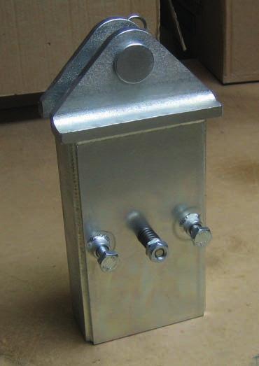
5 The Clamp Post Set up 1. Ensure correct size post box is used for the size of post to be tested. 2. Unscrew clamping bolts fully.. Place Post Box fully over the post to be tested ensuring it is at 90 degrees. 4. TIgnten clamping bolts until post box is secure. Side section Clamping bolts Post to be tested Post to be tested Setup Overview Fig A TIMBER BAULK REACTION VEHICLE FLAT BASE (M) Extension leg (H) Cylinder top adaptor Measure distance (Md) Height of loading (L) BOX SLIP LOCK (F) PUSH LOAD INDICATOR (S1) T SECTION STILL Z SECTION STEEL S Page 5
6 CALCULATIONS 1. Results are to be recorded on the Form PTE/Rev A. 2. The deflection of the post must be measured 600mm above either: a) the edge of the *paved surface, if the traffic face of the fence is within 1.5 metres of the edge (Diagram 1), or b) the finished ground level or top of the concrete footing, whichever is higher, when the traffic face of the fence is more than 1.5 metres from the edge of the *paved surface (Diagram 2).. Bending Moment on the Post/Foundation (BM) = W x L where: W = Load in Newtons indicated on the load indicator L = The height in metres between the point of loading and either: a) the edge of the *paved surface, if the traffic face of the fence is within 1.5 metres of the edge, or b) the finished ground level or top of the concrete footing, whichever is smaller, when the traffic face of the fence is more than 1.5 metres from the edge of the *paved surface. 4. The post foundation is acceptable if a BM of 6000Nm is achieved without the deflection exceeding 100mm. For (100x2) and (110 x 50) steel posts, and: A BM of 9000Nm is achieved without the deflection exceeding 150mm on (125 x 90) steel and (150 x 150) timber. * Paved surface is defined as that which comprises carriageway and hard shoulder / hard strips. VEHICLE RESTRAINT SYSTEMS (ENGINEERS MODULE) Diagram 1 Diagram 2 Load W Load W verge Up to 1.5m To face a beam Carriageway or Hard surface verge over 1.5m To face a beam Carriageway or Hard surface W = Load in ram (push) in Newtons L = Height of load point in Metres (See above) Bending Moment (BM) = L x W BM (Nm) Load to be applied by ram = L (metres) Newtons For TCB/OBB/WR the BM = 6000Nm For UCB & DROBB the BM = 9000Nm Max deflection permitted at full Bending Moment = 100mm All loads to be applied horizontally and perpendicular to axis of post. All test to be done in accordance with the Highways Agency Interim Requirements for Road Restraint Systems and the Non-Proprietary Safety Barrier System Drawings. Gauges for ram may read in either Newtons or kilo Newtons (1KN = 1000N). Page 6
7 VEHICLE SAFETY FENCE FOUNDATION TEST RESULTS Date:... Site:... Job No.... Order No.... *=Delete as appropriate Test No. Details of Post Type of Post: Size of Post Set Back: Max BM Nm or 9000Nm * Ht to load point (L): Max Load required (BM/L): Location metres N Push/ Pull * Load Offset Remarks (N) (mm) Max. Deflection Test No. Details of Post Type of Post: Size of Post Set Back: Max BM Nm or 9000Nm * Ht to load point (L): Max Load required (BM/L): Location metres N Push/ Pull * Load Offset Remarks (N) (mm) Max. Deflection Test No. Details of Post Type of Post: Size of Post Set Back: Max BM Nm or 9000Nm * Ht to load point (L): Max Load required (BM/L): Location metres N Push/ Pull * Load Offset Remarks (N) (mm) Max. Deflection TEST UNDERTAKEN BY: - (NAME)... (SIGNATURE)... DATE... Form PTE/Rev A
Fabricated from grade S x400 steel box section the extensions are quickly assembled into the required
 Description Highly versatile, simple to assemble, heavy duty, modular bracing strut system designed primarily to be used as intermediate struts with MGF hydraulic bracing systems. The system can also be
BRACING STRUT SYSTEMS SECTION 4
 BRACING STRUT SYSTEMS SECTION 4 01942 402 704 www.mgf.ltd.uk MGF 200 Series Strut 4.1 MGF 300 Series Strut 4.2 MGF 400 Series Strut 4.3 MGF 600 Series Strut 4.4 MGF 1000 Series Strut 4.5 MGF Bracing Strut
BRACING STRUT SYSTEMS SECTION 4
 BRACING STRUT SYSTEMS SECTION 4 0808 1153 122 design@mgf.ltd.uk mgf.ltd.uk MGF 200 Series Strut 4.1 MGF 300 Series Strut 4.2 MGF 400 Series Strut 4.3 MGF 600 Series Strut 4.4 MGF 1000 Series Strut 4.5
MGF TECHNICAL FILE MGF 600 SERIES STRUT. Description. Product Notes.
 Description Simple to assemble, heavy duty, modular bracing strut systems designed primarily to be used as cross struts with the MGF 305/406 UC hydraulic bracing system on major excavations. The system
Morehouse Instrument Company
 The Morehouse Universal Calibrating Machine is designed to use a compression force standard, proving ring or load cell to calibrate units under test in compression and tension. The reference standard and
truck crane 140 tons link-belt htc-3140lb BOOM LENGTHS: 42 to 195 ft JIB LENGTHS: 38 to 109 ft JIB OFFSETS:
 truck crane 140 tons link-belt htc-3140lb BOOM LENGTHS: 42 to 195 ft JIB LENGTHS: 38 to 109 ft JIB OFFSETS: 2-15 - 30-45 NOTES: Technical Data Specifications & Capacities Telescopic Boom Truck Crane 140
Technical Data MM Channel
 Technical Data MM Channel The enclosed pages are taken from the Installation Systems Catalogue 2015 for additional information please visit the technical library at www.hilti.co.uk or call our Technical
1 TONNE FOLDING CRANE. 1 TONNE FOLDING CRANE MODEL No CFC100 PART No OPERATING & MAINTENANCE INSTRUCTIONS 1202
 1 TONNE FOLDING CRANE 1 TONNE FOLDING CRANE MODEL No CFC100 PART No 7611005 OPERATING & MAINTENANCE INSTRUCTIONS 1202 2 11 SPARE PARTS No Description Qty Part No No Description Qty Part No 1 Main Support
Operation and Maintenance Instructions
 Hydratight Limited Bentley Road South Darlaston West Midlands WS10 8LQ United Kingdom Tel: +44 121 50 50 600 Fax: +44 121 50 50 800 E-mail: enquiry@hydratight.com Website: www.hydratight.com HNOFC062490400
TYPICAL SPECIFICATION ECP Steel Pier PPB-300 Utility Bracket System
 1.01 Typical Installation Scope TYPICAL SPECIFICATION ECP Steel Pier PPB-300 Utility Bracket System Section 1- General Furnish labor, equipment, tools and material to install the PPB-300 Steel Piers as
HYDRAULIC BODY REPAIR KIT
 HYDRAULIC BODY REPAIR KIT Distributed by Kincrome Group www.kincrome.com.au Owner s Assembly and Operating Manual SPECIFICATIONS... 2 IMPORTANT SAFETY INFORMATION... 3 UNPACKING HYDRAULIC BODY REPAIR KIT...
BOLTING PROBLEM SOLVERS SINCE 2004
 BOLTING PROBLEM SOLVERS SINCE 2004 OFFICE TEL : 1-484-539-9022 FAX : 1-866-780-9316 SALES : BOLTING@NIBTORQUE.COM WEB : WWW.NIBTORQUE.COM . MADE IN THE U.S.A. FROM AIRCRAFT GRADE T6 7075 ALUMINUM HYDRAULICS:
LM5200 milling machine
 LM5200 milling machine 2013 10 LM52 Linear and Gantry Milling in one machine, for X-Axis travel of up to 84 inches (2133.6 mm) and Y-Axis travel of up to 34 inches (863.6 mm). The Climax LM5200 Milling
Ch. 157 ESTABLISHED SOUND LEVELS CHAPTER 157. ESTABLISHED SOUND LEVELS
 Ch. 157 ESTABLISHED SOUND LEVELS 67 157.1 CHAPTER 157. ESTABLISHED SOUND LEVELS Subchap. A. GENERAL PROVISIONS... 157.1 B. NOISE LIMITS... 157.11 C. ADMINISTRATIVE PROVISIONS... 157.21 D. INSTRUMENTATION...
T 775. truck crane 75 ton capacity. range diagram & lifting capacities. Range Diagram (40' - 126' boom)
") T 7 truck crane ton capacity range diagram & lifting capacities DEFLECTIONS NOT SHOWN 6' - 9" 4' - 8" DIMENSIONS ARE FOR LARGEST FACTORY FURNISHED HOOK BLOCK AND HOOK & BALL, WITH ANTI-TWO BLOCK ACTIVATED
T 7 truck crane ton capacity range diagram & lifting capacities DEFLECTIONS NOT SHOWN 6' - 9" 4' - 8" DIMENSIONS ARE FOR LARGEST FACTORY FURNISHED HOOK BLOCK AND HOOK & BALL, WITH ANTI-TWO BLOCK ACTIVATED
Plug (male) Jack (female) Interface dimensions conformable to the standards: min. max. min. max. A B C D E H I
 Jack (female) Interface dimensions conformable to the standards: min. max. min. max. A B C D E H I") Plug (male) Plug Jack min. max. min. max. A B C D E H I Jack (female) Interface dimensions conformable to the standards: 279 Electrical data Requirements Mechanical data Requirements Environmental data
Plug (male) Plug Jack min. max. min. max. A B C D E H I Jack (female) Interface dimensions conformable to the standards: 279 Electrical data Requirements Mechanical data Requirements Environmental data
HEAVY DUTY TROLLEY JACK. Operation Manual
 HEAVY DUTY TROLLEY JACK 4T Operation Manual Make sure to read and fully understand the instruction manual before using this product and keep the manual properly 1 General Description Product Description
USE OF ENERPAC HYDRAULIC EQUIPMENT PRESENTED BY: HARDISH TRIVEDI
 USE OF ENERPAC HYDRAULIC EQUIPMENT 1 PASCAL S LAW Pressure applied at any point upon a confined liquid, is transmitted equally in all the directions & acts perpendicular to the surfaces with equal force.
OPERATOR S MANUAL Model 60010
 OPERATOR S MANUAL Model 60010 10- TON SNAP LOCK PORTA POWER SET W/ WHEELED CASE PROFESSIONAL HYDRAULIC JACKS 1531 W. Mohawk Drive Phone 715-453-9602 Customer Service 800-995-2250 Tomahawk, WI 54487 Fax
Typical Specifications for ECP Helical Torque Anchors
 Chapter 4 Typical Specifications for ECP Helical Torque Anchors ECP Helical Torque Anchors New Construction Piles 73 Helical Torque Anchor Underpinning With Foundation Bracket 79 ECP Helical Torque Anchor
LM5200 MILLING MACHINE
 LM5200 MILLING MACHINE Linear and Gantry Milling in one machine, for X-Axis travel of up to 84 inches (2133.6 mm) and Y-Axis travel of up to 34 inches (863.6 mm). 04 2018 LM52 The Climax LM5200 Milling
Range Diagram and Lifting Capacity T Cranes RANGE DIAGRAM BOOM
 Range Diagram and Lifting Capacity T340-1 Cranes RANGE DIAGRAM 30-94 BOOM Dimensions are for largest factory furnished hook block and hook & ball, with anti-two block activated COUNTER WEIGHT BOOM LENGTH
Cranes. Range Diagram and Lifting Capacity RT TON LIFTING CAPACITY RANGE DIAGRAM 33' - 110' BOOM
 Range Diagram and Lifting Capacity Cranes 55 TON LIFTING CAPACITY RANGE DIAGRAM 33' - 110' BOOM Dimensions are for largest factory furnished hook block and hook & ball, with anti-two block activated COUNTER
LINK-BELT MODEL HTC-8675LB - 75 TON CAPACITY 48 7" (.80m) 41 0" /8" (3.52m) /16" (2.02m) /4" (.34m) 25" 11 0" (.
 41 0 /8 (3.52m) /16 (2.02m) /4 (.34m) 25 11 0 (.") LIFTING CHARTS - Hydraulic Truck Cranes LINK-BELT MODEL - 75 TON CAPACITY 41 0" (12.50m) 48 7" (14.80m) C L Of Rotation 13 8 1/8" (4.17m) 7 0" (2.13m) 4 5/8" (118mm) 11 6 7/8" (3.52m) 6 7 11/16" (2.02m)
LIFTING CHARTS - Hydraulic Truck Cranes LINK-BELT MODEL - 75 TON CAPACITY 41 0" (12.50m) 48 7" (14.80m) C L Of Rotation 13 8 1/8" (4.17m) 7 0" (2.13m) 4 5/8" (118mm) 11 6 7/8" (3.52m) 6 7 11/16" (2.02m)
LM5200 MILLING MACHINE
 LM5200 MILLING MACHINE 2017 12 LM52 Linear and Gantry Milling in one machine, for X-Axis travel of up to 84 inches (2133.6 mm) and Y-Axis travel of up to 34 inches (863.6 mm). The Climax LM5200 Milling
Cranes. Range Diagram and Lifting Capacity RT TON LIFTING CAPACITY RANGE DIAGRAM 40' - 126'
 Range Diagram and Lifting Capacity Cranes 80 TON LIFTING CAPACITY RANGE DIAGRAM 40' - 126' BOOM Dimensions are for largest factory furnished hook block and hook & ball, with anti-two block activated COUNTER
Range Diagram and Lifting Capacity RT230. Cranes 30 TON LIFTING CAPACITY RANGE DIAGRAM 30' - 94' BOOM REDUCTION IN MAIN BOOM CAPACITY
 Range Diagram and Lifting Capacity Cranes 30 TON LIFTING CAPACITY RANGE DIAGRAM 30' - 94' BOOM Dimensions are for largest factory furnished hook block and hook & ball, with anti-two block activated COUNTER
reinforcing bar splicing COUPLER INSTRUCTION MANUAL
 reinforcing bar splicing COUPLER INSTRUCTION MANUAL copyright 004 Erico BV EBV - 039700 - CRP1 - GB 0 CONTENTS 0. CONTENTS PAR SUBJECT PAGE 0. CONTENTS 0-1 1. LENTON COUPLER TYPE OVERVIEW 1-1. TORQUE WRENCHES
ArmorGuard Barrier Portable Longitudinal Barrier
 ArmorGuard Barrier Portable Longitudinal Barrier Installation & Maintenance Manual AGB I&M 082409 Page 1 of 12 ArmorGuard Barrier Table of contents Preface... 2 Applications and System Characteristics
CRANE RATING MANUAL HTC
 SERIAL NUMBER: XXXX- XXXX CRANE RATING MANUAL HTC- 8611 TELESCOPIC BOOM TRUCK CRANE - 164.1 SIX SECTION LATCHING BOOM For Replacement, Order Part Number: T2P38 (116) R Link-Belt is a registered trademark.
LM6200 milling machine
 LM6200 milling machine Linear and Gantry Milling in one machine, with x-axis travel up to 176 inches (4470.4 mm) and y-axis travel up to 106 inches (2692.4 mm) 4 2013 LM62 The Climax LM6200 Milling Machine
FRONT AXLE GROUP 11A CONTENTS 11A-0. SECTION 0 GENERAL Removal 3 SECTION 1 FRONT AXLE HUB 1
 11A-0 GROUP 11A FRONT AXLE CONTENTS SECTION 0 GENERAL 1 1-1 Removal 3 SECTION 1 FRONT AXLE HUB 1 1-2 Inspection 3 1-3 Installation 4 1. Removal and Installation 1 1-1 Removal 1 SECTION 3 WHEEL ALIGNMENT
RTC 8050 Series II. 50 ton (45.36 metric tons) Telescopic Boom Rough Terrain Crane
 Telescopic Boom Rough Terrain Crane") Telescopic Boom Rough Terrain Crane RTC 85 Series II 5 ton (45.36 metric tons) Boom and Fly Capacities for this machine are listed by the following sections. Working Range Diagram 35.5 to 6.3 (1.82 18.38
Telescopic Boom Rough Terrain Crane RTC 85 Series II 5 ton (45.36 metric tons) Boom and Fly Capacities for this machine are listed by the following sections. Working Range Diagram 35.5 to 6.3 (1.82 18.38
FULLY HYDRAULIC TRUCK CRANE
 CRANE Description Model Specification Maximum rated lifting capacity length Fly jib length Maximum lifting height Main Hoisting line winch speed Auxiliary winch Main Hoisting winch speed Auxiliary winch
LM6200 MILLING MACHINE
 LM6200 MILLING MACHINE 2018 04 LM62 3-Axis Linear and Gantry Milling The CLIMAX LM6200 Linear/Gantry Milling Machine revolutionizes both the capabilities and functionality of portable mills. Four main
Spring hangers, spring supports
 Spring hangers, spring supports 2 spring Spring hangers, supports PRODUCT 2 GROUP Spring hangers, spring supports Contents Page Field of application...2.1 Overview of spring hangers and spring supports...2.3
Operation and Maintenance Instructions
 Hydratight Limited Bentley Road South Darlaston West Midlands WS10 8LQ United Kingdom Tel: +44 121 50 50 600 Fax: +44 121 50 50 800 E-mail: enquiry@hydratight.com Website: www.hydratight.com TOP COLLAR
OPERATION MANUAL FOR SQUARE DRIVE & LOW PROFILE HYDRAULIC TORQUE WRENCHES NOTICE WARNING
 OPERATION MANUAL FOR SQUARE DRIVE & LOW PROFILE HYDRAULIC TORQUE WRENCHES NOTICE Hydraulic Torque Wrenches are designed for installing and removing large bolts having minimal wrench clearance at offshore
For sales use only CRANE RATING MANUAL. RTC-8090 Series II 5 - Section Boom. Not for crane operations SERIAL NUMBER: XXXX-XXXX
 SERIAL NUMBER: XXXX-XXXX CRANE RATING MANUAL RTC-8090 Series II 5 - Section Boom For Replacement, Order Part Number: N4P0090 (110509) R Link-Belt is a registered trademark. 1of96 N4P0091 Table Of Contents
Congratulations on purchasing the epump solar pumping solution.
 Congratulations on purchasing the epump solar pumping solution. Please follow the easy step by step assembly instructions below. We also have an assembly video which can be viewed via our website Assembly
CRANE RATING MANUAL HTC
 SERIAL NUMBER: CRANE RATING MANUAL 5---Section Boom For Replacement, Order Part Number: N3P0199 (031907) R Link-Belt is a registered trademark. 1of244 N3P0200 Table Of Contents Page Contents 3---4 Operating
Range Diagram and Lifting Capacity T Cranes. View thousands of Crane Specifications on FreeCraneSpecs.com RANGE DIAGRAM BOOM
 Range Diagram and Lifting Capacity Cranes RANGE DIAGRAM 30-94 BOOM Dimensions are for largest factory furnished hook block and hook & ball, with anti-two block activated COUNTER WEIGHT BOOM LENGTH UPPERSTRUCTURE
RT555 TEREX. rough terrain crane 55 ton capacity. range diagram & lifting capacities. Range Diagram ( boom) HOOK BLOCK WEIGHTS
 HOOK BLOCK WEIGHTS") TEREX RT5 rough terrain crane ton capacity range diagram & lifting capacities DIMENSIONS ARE FOR LARGEST FACTORY FURNISHED HOOK BLOCK AND HOOK & BALL, WITH ANTI-TWO BLOCK ACTIVATED Range Diagram (33-1
TEREX RT5 rough terrain crane ton capacity range diagram & lifting capacities DIMENSIONS ARE FOR LARGEST FACTORY FURNISHED HOOK BLOCK AND HOOK & BALL, WITH ANTI-TWO BLOCK ACTIVATED Range Diagram (33-1
M60/M62 smart motorways
 Public information exhibition Highways England creative N150128 Welcome We re improving the M60 between junction 8 (Carrington Spur) and M62 junction 20 (Rochdale and Oldham). The M60 and M62 are vital
Instruction Manual. Single Acting, Pancake, Locking Collar Hydraulic Cylinders RPLC Series. Maximum Operating Pressure 700 bar
 Single Acting, Pancake, Locking Collar Hydraulic Cylinders RPLC Series Maximum Operating Pressure 700 bar ABSOLUTE EQUIPMENT PTY LTD 2/186 Granite Street, GEEBUNG QLD 4034 Australia sales@absoluteequipment.com.au
Range Diagram and Lifting Capacity RT665. Cranes 65 TON LIFTING CAPACITY RANGE DIAGRAM 36' - 111' BOOM REDUCTION IN MAIN BOOM CAPACITY
 Range Diagram and Lifting Capacity Cranes 65 TON LIFTING CAPACITY RANGE DIAGRAM 36' - 111' BOOM DIMENSIONS ARE FOR LARGEST FACTORY FURNISHED HOOK BLOCK AND HOOK & BALL, WITH ANTI-TWO BLOCK ACTIVATED COUNTER
SHEYENNE TELE-BOOM OWNERS MANUAL OPERATOR INSTRUCTIONS PARTS BOOK
 SHEYENNE TELE-BOOM OWNERS MANUAL OPERATOR INSTRUCTIONS PARTS BOOK 701 Lenham Ave. SW PO Box 647 Cooperstown ND 58425 1-800-797-1883 701-797-2700 * 701-797-2584 Fax www.sheyennemfg.com TABLE OF CONTENTS
Rubbish Chutes Operating & Assembly Instructions
 Rubbish Chutes Operating & Assembly Instructions Conveying and Hoisting Solutions Pty Ltd ABN: 78 163 105 744 1. Purpose of Equipment Rubbish Chute systems are intended for the guidance of falling material
BOLT TENSIONERS. carefully before use and retain it for reference.
 BOLT TENSIONERS This manual contains IMPORTANT WARNINGS, CAUTIONS and other instructions. Read and understand the instructions manual carefully before use and retain it for reference. TORCUP MIDDLE EAST
Hydraulic Jack Training
 Hydraulic Jack Training This Training Topic is a supplement to the Brieser Safety Training titled, Hand and Portable Powered Tool Safety, which discusses tool safety in general. This training summarizes
HT125KM, FA3TM, FA6TE
 HT125KM, FA3TM, FA6TE FLANGE ALIGNMENT TOOLS Operator Instruction Manual info@equalizerinternational.com www.equalizerinternational.com INNOVATION IN ITS MOST FUNCTIONAL FORM INDEX SECTION CONTENTS PAGE
NGR NGR NEUTRAL GROUNDING RESISTOR
 NGR NGR NEUTRAL GROUNDING RESISTOR Installation and Maintenance Instruction Manual C-100EM, September 2014 NEUTRAL GROUNDING RESISTORS WARNING Neutral Grounding (Earthing) resistors, like all high voltage
The Rail Cap allows a train to travel over broken rails with up to 125mm of separation at a maximum speed of 15km/hour.
 Rail Anchor Part No. 1121023 Mobile Sliding Anchor Point, ideal when working at heights Rail Cap Part No. 1121206 The Rail Cap allows a train to travel over broken rails with up to 125mm of separation
ELGC-BS-KF. Spindle axis. Instructions Operating c [ ]
![ELGC-BS-KF. Spindle axis. Instructions Operating c [ ]](/thumbs/88/115778972.jpg "ELGC-BS-KF. Spindle axis. Instructions Operating c [ ]") ELGC-BS-KF Spindle axis Instructions Operating 8095590 8095590 2018-08c [8095592] Translation of the original instructions 2 Festo ELGC-BS-KF 2018-08c Table of contents 1 Further applicable documents...
ELGC-BS-KF Spindle axis Instructions Operating 8095590 8095590 2018-08c [8095592] Translation of the original instructions 2 Festo ELGC-BS-KF 2018-08c Table of contents 1 Further applicable documents...
LOAD CHARTS TMS9000E 85% STABILITY SERIAL NUMBER
 LOAD CHARTS TMS9000E 85% STABILITY SERIAL NUMBER TMS9000E - S/N 1 TMS9000E - S/N 2 CONTENTS GENERAL NOTES...11 WEIGHT REDUCTIONS AND WARNING NOTES... 12 COUNTERWEIGHT CONFIGURATIONS... 13-15 LIFTING AREA
12.3 Full Roller Type, MSR Series
 12.3 Full Roller Type, MSR Series A. Construction Carriage End Seal Grease Nipple End Cap Inner Seal Roller Bottom Seal 45 Rail 45 B. Characteristics The full roller type linear guideway, MSR series, equip
PAPI System Hella Induperm type 801 USER MANUAL GB
 PAPI System Hella Induperm type 801 USER MANUAL GB LIST OF CONTENT 1. General information... 3 1.1 The layout of this manual... 3 1.2 The use of the manual... 3 1.3 Manufacturer information... 3 1.4 Document
Cranes. Range Diagram and Lifting Capacity RT345-1XL 45 TON LIFTING CAPACITY RANGE DIAGRAM 33.75' - 105' BOOM
 Range Diagram and Lifting Capacity RT345-1XL Cranes 45 TON LIFTING CAPACITY RANGE DIAGRAM 33.75' - 105' BOOM DIMENSIONS ARE FOR LARGEST FACTORY FURNISHED HOOK BLOCK AND HOOK & BALL, WITH ANTI-TWO BLOCK
CONTENTS 1. SIGN ANALYSIS 2. SECURITY EQUIPMENT SELECTION CRITERIA 3. PRODUCT INTRODUCTION 4. GENERAL RULES 5. CONNECTION OF SECURITY EQUIPMENT
 CONTENTS 1. SIGN ANALYSIS 2. SECURITY EQUIPMENT SELECTION CRITERIA 3. PRODUCT INTRODUCTION 4. GENERAL RULES 5. CONNECTION OF SECURITY EQUIPMENT 6. MAINTENANCE DETAILS 7. GENERAL CONDITIONS TO BE PAID ATTENTION
Torque Wrenches
 - 171 - Digital Torque Wrenches Digital Torque Wrenches The new AmPro digital torque wrenches are designed for simple and precise measurement of industrial, automotive, aerospace and many other applications.
TEST REPORT. Ceram Reference: (QT21489/2/SL)/Ref: 1.0A. Tensile and Frictional Tests on the Fast Fit BeamClamp Systems.
/Ref: 1.0A. Tensile and Frictional Tests on the Fast Fit BeamClamp Systems.") TEST REPORT Ceram Reference: 121557 (QT21489/2/SL)/Ref: 1.0A Project Title: Tensile and Frictional Tests on the Fast Fit BeamClamp Systems Client: Kee Safety Limited For The Attention of: Mr Phil Higgs
TEST REPORT Ceram Reference: 121557 (QT21489/2/SL)/Ref: 1.0A Project Title: Tensile and Frictional Tests on the Fast Fit BeamClamp Systems Client: Kee Safety Limited For The Attention of: Mr Phil Higgs
ArmorGuard Barrier Portable Longitudinal Barrier
 ArmorGuard Barrier Portable Longitudinal Barrier Installation & Maintenance Manual AGB I&M 112811 Page 1 of 13 ArmorGuard Barrier Table of contents Preface... 2 Applications and System Characteristics
LM Guide Radial Type Model SR
 LM Guide Radial Type Model Endplate LM block Grease nipple End seal LM rail 90 Ball Retainer plate Side seal (Optional) Cross section 30 Point of Selection A Point of Design Options Model No. Precautions
C N C. S y n c h r o. H y d r a u l i c
 C N C S y n c h r o H y d r a u l i c P r e s s B r a k e E n g i n e e r e d t o p e r f e c t i o n... CNC Press Brake CNC Controller 5 CNC Controller 7" Full Colour TFT Touch Screen Display - Selection
Draft Indian Standard PERFORMANCE REQUIREMENTS AND METHODS OF TEST FOR WHEELS FOR PASSENGER CARS/MINI GOODS CARRIERS (First Revision of IS 9436)
") Draft for comments only Draft Indian Standard PERFORMANCE REQUIREMENTS AND METHODS OF TEST FOR WHEELS FOR PASSENGER CARS/MINI GOODS CARRIERS (First Revision of IS 9436) Not to be reproduced or used as
Draft for comments only Draft Indian Standard PERFORMANCE REQUIREMENTS AND METHODS OF TEST FOR WHEELS FOR PASSENGER CARS/MINI GOODS CARRIERS (First Revision of IS 9436) Not to be reproduced or used as
Health, Safety, Security and Environment
 Document owner and change code Document Owner Aaron Perronne Title HSSE Manager Mark X Change Code Description X N/A First Issue A Typographical/Grammatical correction; formatting change; text clarification-no
TECHNICAL MANUAL CALIBRATION PROCEDURE FOR MANUALLY OPERATED TORQUE WRENCHES 6% TO 20% (GENERAL)
") TECHNICAL MANUAL CALIBRATION PROCEDURE FOR MANUALLY OPERATED TORQUE RENCHES 6% TO 20% (GENERAL) Distribution Statement - Distribution authorized to U. S. Government agencies and their contractors for official
TECHNICAL MANUAL CALIBRATION PROCEDURE FOR MANUALLY OPERATED TORQUE RENCHES 6% TO 20% (GENERAL) Distribution Statement - Distribution authorized to U. S. Government agencies and their contractors for official
groundworks technical reference section 4 : double acting hydraulic braces supplement supershaft plus technical details
 groundworks technical reference section 4 : double acting hydraulic braces supplement supershaft plus technical details Issue 4 January 2016 Supershaft Plus is a modular hydraulic system. outer sleeve
FPC835M Air Hydraulic Rivet Tool
 WARRANTY If you have any problems with this tool, please call FPC Corporation toll-free at -800-860-3838 before returning it to the place of purchase. FPC835M Air Hydraulic Rivet Tool FPC Corporation warrants
Lockinex. Armco Crash Barrier. great service, great quality. W Section, W section Plus1 & Box Beam type. Material grade BS EN S275
 Armco Crash Barrier W Section, W section Plus1 & Box Beam type. Material grade BS EN 10025 S275 Galvanised to BS EN 1461:2009 Lockinex great service, great quality INTRODUCTION Lockinex Armco Barriers
FLORIDA RURAL WATER ASSOCIATION 2970 Wellington Circle Tallahassee, FL Telephone: ~ Fax:
 FLORIDA RURAL WATER ASSOCIATION 2970 Wellington Circle Tallahassee, FL 32309-6885 Telephone: 850-668-2746 ~ Fax: 850-893-4581 Lift Station Bypass Pump & Connection Assembly Instructions Loss of power during
Fig Variable Speed Valve Parts
 5 DISASSEMBLY OF VARIABLE SPEED CONTROL VALVE (Seal Replacement with Control Valve in the Bobcat). Remove seat and seat plate (Fig. ).. Remove variable speed control lever linkage rod. 3. Remove temperature
Aluminum Box Culverts
 Steel and Aluminum s The Solution for Small Bridge Replacement: s Contech s are a practical and costefficient solution for small bridge replacement. They have a lower installed cost because they are faster
Model Torque Multiplier
 Model 8111-8112 Torque Multiplier OPERATING INSTRUCTIONS Page 1 of 6, REV. B The Sweeney 8111 and 8112 Torque Multipliers provide maximum power for breakaway and maximum speed for run-off of large threaded
KAN-therm System. Series 71A, 75A, 51A, 55A manifolds. installation and maintenance instructions
 instrukcja_rozdzielacz71a-55a_pl_ru_en:print 2010-09-30 14:14 Strona 25 KAN-therm System Series 71A, 75A, 51A, 55A manifolds installation and maintenance instructions Series 71A and 75A manifolds Installation
20 TONNE HYDRAULIC PRESS MODEL NO: CSA20FBT
 20 TONNE HYDRAULIC PRESS MODEL NO: CSA20FBT PART NO: 7614058 OPERATION & MAINTENANCE INSTRUCTIONS WARNING: Read these instructions before using the press GC0516 INTRODUCTION Thank you for purchasing this
Instruction Manual. Single Acting, High Tonnage, Low Height Cylinders RSH Series. Maximum Operating Pressure 700 bar
 Single Acting, High Tonnage, Low Height Cylinders RSH Series Maximum Operating Pressure 700 bar ABSOLUTE EQUIPMENT PTY LTD 2/186 Granite Street, GEEBUNG QLD 4034 Australia sales@absoluteequipment.com.au
Ground Fault Cable Retractor GR900 Series Service Manual
 AERO-MOTIVE COMPANY A Woodhead Industries, Inc. Subsidiary Ground Fault Cable Retractor GR900 Series Service Manual IMPORTANT SAFETY INSTRUCTIONS Please read this manual carefully and follow its instructions.
OPERATING INSTRUCTION
 OPERATING INSTRUCTION QL-MH Model In order to use the torque wrench properly and safely, please read this instructions before operation. If any questions, please contact to Tohnichi authorized distributor
Non-contact Deflection Measurement at High Speed
 Non-contact Deflection Measurement at High Speed S.Rasmussen Delft University of Technology Department of Civil Engineering Stevinweg 1 NL-2628 CN Delft The Netherlands J.A.Krarup Greenwood Engineering
12.5 Ball Chain Type, SME Series
 12.5 Ball Chain Type, SME Series A. Construction Carriage End Cap End Seal Grease Nipple Inner Seal Ball Bottom Seal Ball Chain 45 Rail 45 B. Characteristics The ball chain type linear guideway, SME series,
TYPICAL SPECIFICATION
 TYPICAL SPECIFICATION ECP Steel Pier PPB 350 Utility Bracket System, TA-150 Torque Anchor Tieback and PPB 350-TA Tieback Adapter Assembly Section 1- General 1.01 Typical Installation Scope Furnish labor,
04 Spanners and Wrenches
 04 Spanners and Wrenches ouble open end spanner 73 Open slogging wrench 75 Combination Insulated wrench 75 76 spanner Offset ring spanner 78 Ring slogging wrench 80 Flat ring spanner 81 Offset ratchet
Model PM5000 Portable Milling Machine
 Model PM5000 Portable Milling Machine Features Applications Setup & Operation Components & Accessories Technical Data CLIMAX Portable Machine Tools, Inc. 05/99 1 Portable on-site milling solves your difficult
ABN Quality Endorsed Company ISO9001 Lic No EDITION 2
 ABN 43 8 71 335 SECTION 4 Cable Ladder and A U S T R A L I A W I D E A U S T R A L I A N M A D E Quality Endorsed Company ISO91 Lic No 13146 EDITION 2 SECTION 4: Cable Ladder & Type 3/5 Type 4/7L Type
Interlocks 200 Series
 rd 12070 43 St. NE, St. Michael, MN 55376 763-497-7000 www.tcamerican.com sales@tcamerican.com Installation Instructions Interlocks 200 Series 2I-515; 2I-930 2I-513; 2I-850 Crane Interlock and Operating
3800, 5000, 6000, 6500 & 8000# Lifts
 FLOE 24 volt VSD Drive 3800, 5000, 6000, 6500 & 8000# Lifts P/Ns 511-38500-00, 511-60020-00, 511-80020-00 ASSEMBLY INSTRUCTIONS TOOLS REQUIRED: (2) 3/4 socket or wrench for 1/2 nuts and bolts (1) 9/16
Subsoiler. 3, 5 and 7 Leg Mounted Subsoilers. Shear Pin. Auto Reset. Parts list and Operators Manual
 Subsoiler, 5 and 7 Leg Mounted Subsoilers Shear Pin Auto Reset Parts list 007-009 and Operators Manual www.sumo.com The Airfield Full Sutton York YO4 HS Tel. 0759 7700 Fax. 0759 700 .0 Registration Please
OVERLOAD CLUTCHES FOR INDEX DRIVES
 The Driving Force in Automation OVERLOAD CLUTCHES FOR INDEX DRIVES WARNING WARNING This is a controlled document. It is your responsibility to deliver this information to the end user of the CAMCO indexer.
Tools Required. Metric Wrench Set Screwdriver Set Metric Socket Set Pliers Heavy duty hydraulic Jack and Car Stands Box knife or similar Hacksaw WD40
 Subaru 2004+ Legacy GT & Outback XT For JDM 2.0 twinscroll turbo and USDM 2.5 turbo models Front Mount Intercooler Fitting Instructions PN# LEG-1348-000 You are now the proud owner of a highly tested and
AURELIA LTD A59 EXCAVATOR 360 ABOVE 10 TONNES INC LIFTING TECHNICAL TEST THEORY CPCS Issue 09-Jul-2012
 Name THREE ways that a plant operator can contribute in ensuring repeat business with the client or principal contractor. What is the meaning of this hand signal (being demonstrated by the tester)? What
OPERATION AND MAINTENANCE MANUAL
 WREN IBT SERIES HYDRAULIC TORQUE WRENCHES IBT SQUARE DRIVE SERIES OPERATION AND MAINTENANCE MANUAL FOR WREN Products: POINT 75, 1IBT, 3IBT, 5IBT, 8IBT, 10IBT, 20IBT, 25IBT, 35IBT, 50IBT SQUARE DRIVE HYDRAULIC
MODEL NUMBER: MEDIUM DUTY ONBOARD AIR SYSTEM
 MODEL NUMBER: 10003 MEDIUM DUTY ONBOARD AIR SYSTEM IMPORTANT: It is essential that you and any other operator of this product read and understand the contents of this manual before installing and using
Technical data/component parts
 Technical data/component parts Demag pillar and wall-mounted slewing jib cranes 191214 en GB 203 814 44 714 IS 132 Manufacturer Terex MHPS GmbH Forststrasse 16 40597 Düsseldorf, Germany www.demagcranes.com
Mechanisms and Structures. Mechanical Systems. Levers. Basic Forces
 Mechanisms and Structures Mechanical Systems Levers Basic Forces Pupil Name Teacher Class Page 1 MECHANICAL SYSTEMS Our every day lives are made much easier by a variety of mechanical systems that help
Innovative Solutions
 Innovative Solutions 2 1 MK4 Introduction mk MK4 Elastomeric Bearings are deformable structural components constructed partially or wholly from elastomer. They are essentially designed to transmit vertical
OPERATING MANUAL C-1350 CABLE PUSHER. Copyright 2003 by CBS Products (KT), Ltd
, Ltd") CBS Products (KT), Ltd, Pillings Road, Oakham, Rutland, LE15 6QF. UK Telephone: +44(0)1572723665 Fax: +44(0)1572 756006 E-Mail: sales@cbsproducts.com Website:www.cbsproducts.com OPERATING MANUAL C-1350
CBS Products (KT), Ltd, Pillings Road, Oakham, Rutland, LE15 6QF. UK Telephone: +44(0)1572723665 Fax: +44(0)1572 756006 E-Mail: sales@cbsproducts.com Website:www.cbsproducts.com OPERATING MANUAL C-1350
Balancing propeller shaft. In the event of vibration or drumming:
 26 11 030 Balancing propeller shaft In the event of vibration or drumming: Requirements: Propeller shaft in perfect optical condition. Balance propeller shaft if balance plates are missing or propeller
INSTALL SERVICE- ENTRANCE SYSTEMS
 SUBCOURSE EN5141 EDITION B US ARMY ENGINEER SCHOOL INSTALL SERVICE- ENTRANCE SYSTEMS INSTALL SERVICE- ENTRANCE SYSTEMS Subcourse Number EN5141 EDITION B United States Army Engineer School Fort Leonard