AUTOMATIC TERMINAL CRIMPING MACHINE CPR-ZERO INSTRUCTION MANUAL
|
|
|
- Laura Patterson
- 5 years ago
- Views:
Transcription

1 AUTOMATIC TERMINAL CRIMPING MACHINE CPR-ZERO INSTRUCTION MANUAL
2
3 TABLE OF CONTENTS INTRODUCTION 1 STANDARD OPERATION MANUAL 61 KEEP SAFETY IN MAIND 2 Preparation for operation SPECIFICATUONS Supply wire 63 MAIN SPECIFICATIONS 3 Installation of the cut/strip blades 66 Production capacity chart 4 Adjust air pressure 68 NAMES OF MACHINE COMPONENTS Wire clamp 69 NAMES OF MACHINE COMPONENTS 5 Supply terminal 70 NAMES AND FUNCTIONS OF OPERATION PANEL CRIMPING PRESS 71 Operation panel and operation Switches 6 APPLICATOR 75 HOME display 7 PRODUCTION 83 COUNT display 9 INSPECTION AND MAINTENANCE 89 MENU display 15 TROUBLESHOOTING 95 WORK display 16 SPEED display 17 CONTROL UNIT 100 POSITION display 18 Circuit Diagram 101 TIMING display 23 Setting of DIP switch 115 CHECK display 27 Servo parameter setting value 116 SYSTEM display 30 Layout in Control box 118 BANK display 39 AIR UNIT Switches 43 Piping Diagram 119 Using value key 47 DETECTORS PARTS LIST 120 Crimp miss detector 49 CONSUMABLE PARTS LIST 197 Strip miss detector 58
4 INTRODUCTION Thank you for purchasing our machine CPR-ZERO. Before using this machine, please read this user s manual for essential information about installation, functions, operating procedures, maintenance, inspection, and safety precautions. This manual describes important information to use the machine, including the names and functions of the machine s components, operation, maintenance and cautions for handling. We are confident that your CPR-ZERO will operate at its peak efficiency. Keep this manual in its place within the machine for immediate reference. Upon delivery of this machine, please confirm 1. That no damage occurred in shipping. 2. That there are no missing components, and that all components are of the right type. 3. That your order has been correctly filled. For safety In this manual, the following symbols are placed to show the importance for each piece of information. Please understand these symbols to use the machine safely. The symbols indicate the following contents If handled incorrectly, equipment may generate a condition(s) resulting in death or severe injury to the user. If handled incorrectly, equipment may generate a condition(s) resulting in serious injury to the user. If handled incorrectly, equipment may generate a condition(s) resulting in moderate injury to the user, or may cause damage to the equipment. Matters concerning operation and maintenance. 1
5 KEEP SAFETY IN MIND KEEP SAFETY IN MIND This machine places utmost importance in protecting the user from danger for its whole production process (from its design to its finish). Operators and engineers must strictly observe the following during installation, and adjustment in order to avoid harm. 1 Be sure to ground the equipment before connecting any electrical source (equivalent or superior to Grounding Type 3). This minimizes injuries such as electrical shock should there any electrical malfunction. 2 Never remove the safety cover except for inspection. Do not remove the cover. Operating the machine without the cover may cause injury. Turn off the power switch before removing the cover for inspection. 3 Never place hands or fingers in the operating unit or the applicator during Automatic operation. If you are compelled to do so, stop the machine and turn off the power switch first. Then, carry out your work. If you carry out the work with the machine s power ON, an unexpected accident may occur. Be very careful. 4 Communicate during inspection or repair work. When more than one person is Involved in such work, they should caution each other and make others aware what each is going to do. 5 Always turn off the power before placing hand in the machine to change components (such as wire, terminals, or applicators), or to clean the machine. 6 If trouble occurs such as crimping errors, do not carry out work by your finger. Turn off the crimping machine power switch before correcting it. A pair of tweezers is recommended to correct the problem. 2
6 SPECIFICATIONS SPECIFICATIONS Model CPR-ZERO-FX CPR-ZERO-ST Type JA101 JA102 Functions Max Production Capacity Note 1) Wire Size Note 2) Max Cut Length Min Note 3) Cut Length Cue Length Precision Note 4) Strip Length Note 5) Strip Precision Strip Depth Press Applicator Note 6) Detectors Control system Power supply Compressed air Operating temperature range Operating humidity range Warranty period Machine dimensions Measured wire cutting No.1 side: Strip, Half strip, Crimp No.2 side: Strip, Half strip, Crimp Both end crimp: 4,500 pcs/hr (0.80 sec/pc) * 4,000 pcs/hr (0.9 sec/pc) w/ ACH ON 0.03 mm 2 ~ 0.3 mm 2 Wire insulation OD has to be smaller than φ 2.3 mm 20,000 mm (set unit: 1mm) 35 mm * Minimum entry value is 20 mm 4,200 pcs/hr (0.85 sec/pc) 0.3 mm 2 ~ 2.0 mm 2 Wire insulation OD has to be smaller than φ1.4 ~ φ 3.4 mm * FX ASY is necessary for the wire w/ insulation OD smaller than φ1.4 mm Cut length shorter than 100 mm: variance 0.5 mm+ (set cut length x 0.002) Cut length longer than 100 mm: variance 1.0 mm+ (set cut length x 0.002) No.1: 1.0 ~ 10.0 mm (Unit: 0.1mm) * Max Entry Value 17.0 mm No.2: 1.0 ~ 17.0 mm (Unit: 0.1mm) Variance ± 0.1 mm 300 steps (1 step = 0.01 mm) Max Adjust depth 3 mm 19,600N (2.0 ton) Stroke 30 mm * 6,900N (0.7 ton) w/ ACH ON 21,500N (2.2 ton) Stroke 30 mm * ACH ON Standard JAM Applicator AS42 (except X Type) AS40 AE30 Conversion kits are available for other Makers genuine APLs (Option) Air pressure, No wire, Wire overload, Strip miss detector (contact type), Terminal Drop, No terminal, Terminal overload, Safety cover open Electronic control Single-Phase AC230V, Rating 210V ~ 240V 50/60 Hz, 7A Three-Phase AC200V, Rating 190V ~ 240V 50/60Hz, 5A 0.5 MPa, Approx. 100NI/min 15Cº ~ 30Cº Ambient temperature 30% ~ 80% RH, With no dew condensation Three AC200V Rating 190V ~ 240V 50/60 Hz, 16A 2,000 hours or 1 year after delivery(excluding consumables) 920 W x 900 E x 1,430 H (exclude protruding objects) Machine mass Approx. 450 Kgs Approx. 560 Kgs Options Note 8) 920 W x 900 E x 1,435 H (exclude protruding objects) Wire Reel Stand (WRS-BT01, WRS20DR etc.), Paper Winding Device, Non-Cut Carrier Type Pipes, Pat-light, End Terminal Supply, Wire Joint Detector, Genuine APL Conversion KIT Note 7), Non-Cut Carrier Cutter ST ASY ACH Function Note 8) FX ASY Note 1) This data is with Cut Length 35 mm, Strip Length 2 mm, and Crimp Position 5 mm. Productivity may differ with other product setting. Note 2) Certain type or size of wire and terminal cannot be processed. Some wires and terminals require additional set of Rollers or Strip Blades (Option). Note 3) Minimum Wire Cut Length varies depending on No.2 Protruding Length, Strip Length, and Terminal size. Note 4) Precision may vary depending on wire type and size. Note 5) Entry in CRIMP Mode may not be processed depending on Strip length and Protruding length setting. In that case, switch the Mode from CRIMP to STRIP in Select Process Screen. Certain type or size of wire cannot be processed. Note 6) Certain type of Applicator cannot be installed or used for the production. Production capacity may be lower for some type of Applicators. Note 7) Some genuine Applicators from other makers cannot be installed by Conversion KIT. Conversion kit may not be available for certain Makers Applicators. Note 8) Certain type of terminals cannot be processed. When ACH (Option) is set to be ON, productivity and crimping capability decrease dramatically. * Specifications are subject to change without prior notice. 3
7 Products (pc / H) 製作本数 ( 本 /h) Production capacity chart Capacity 生産能力表 table SPECIFICATIONS JA101 JA102 Cut Length (mm) 切断長 (mm) Conditions for measuring the production ability 1. Feed speed: 3 m / sec 2. Feed acceleration: 100 msec 3. Processing mode: Both end crimp 4. Strip length: 2mm or less, Crimp Position: 5mm or less, No.2 Protruding length 23mm 5. Press speed: 1 (3,000 rpm) 6. Strip Pull-back: 0 step 7. Back feed, Press retrieve Mode: OFR * It will be approx. 0.1 sec slower when ACH Mode is ON. (JA101) (1) It is necessary to lower the machine s production ability depending upon the wire type or processing conditions. (2) It is necessary to lower the machine s production ability depending upon the reel stand or the wire feed status. 4
8 NAMES OF MACHINE COMPONTENTS NAMES OF MACHINE COMPONENTS 1. Names of the machine components Refer to the figure shown below when changing the operation timing or the compensation value of each unit. Wire Overload Detector Wire Entry No-wire Detector Straightener Pre Feed Cut / Strip No.2 Crimper No.1 Y Axis Feed No.1 Clamp No.1 Strip Miss Detector Terminal Drop Detector No.1 X Axis No.2 Side Terminal Guide Plate No.1 Side Terminal Guide Plate Operation Panel Eject Clamp No.2 Terminal Drop Detector No.1 Crimper No.2 X Axis Feed wire receiver No.2 Strip Miss Detector No.2 Y Axis No.2 Clamp 5

9 NAMES AND FUNCTIONS OF OPERATION PANEL Names and functions of operation panel 1. The component names and functions on the operation panel are shown below NAME 1 DISPLAY 2 CF CARD COVER 3 POWER SWITCH 4 START 5 STOP 6 RESET 7 EMG. STOP FUNCTION This is a touch panel to display and select Work process data, operating condition, message, etc. You can use CF Guard slot by opening this over. This switch turns on the machine. This is a START switch to start operating machine units. It starts the operation according to the condition selected or set in Display. This switch stops operation. It is used stop cycle in the AUTO mode. This switch is used to reset detected errors on display. This is an emergency stop switch. It can be released by RESET button, and press START button to return to the origin. 6
10 NAMES AND FUNCTIONS OF OPERATION PANEL 3. Name of display and function 1) HOME display The following display called HOME is indicated when the machine completes the Origin search after the power is turned on. Name of HOME display and function The component names on the HOME screen are shown below. 1 Count display 9 Lock switch 2 Work data display 10 CFM panel switch 3 Operation mode setting 11 Process type select switch 4 Process mode setting 12 Preparation setting switch 5 Setting status display 13 Feed: Feed switch 6 Detector On/Off display 14 Feed: Open/Close switch 7 Menu display change switch 15 User definition Panel 8 Bank Display 16 APL select switch 7
 It counts up when the CYCLE or AUTO operation is done in the normal mode. Touch this area to show COUNT Display.")
11 NAMES AND FUNCTIONS OF OPERATION PANEL 1. COUNT DISPLAY 1) This unit displays the set values for the production quantity, lot quantity and their count. Touch this are, and the COUNT screen appears. The total production quantity is displayed on the lower column. (0~ ) It counts up when the CYCLE or AUTO operation is done in the normal mode. Touch this area to show COUNT Display. This indicates the quantity of products in a lot. (0 ~ ) It counts up when the CYCLE or AUTO operation is done in Normal mode. Set quantity is shown in lower column. Press this button to return QTY Count to 0. Touch this area to show Production QTY Change Key. Touch this area to show Value Entry Key. This indicates the number of the processed lots. (0 ~ ) It counts up when the CYCLE or AUTO operation is done in Normal mode. Set lot quantity is shown in lower column. Press this button to return QTY Count to 0. Touch this area to show Production QTY Change Key. Touch this area to show Value Entry Key. This indicates the crimping count on the No.1 side. (0 ~ ) This indicates the crimping count on the No.2 side. (0 ~ ) This indicates the overall production progress. When the gauge reaches to the right end, the production quantity is FULL. Production QTY Change Key Switch to add 1 pc on QTY Count Switch to add 10 pcs on QTY Count Switch to subtract 1 pc on QTY Count Switch to subtract 10 pcs on QTY Count Switch to finish Production QTY Change 8
 <-> 1: Products Lot set value (Lot quantity set) Products quantity")
12 NAMES AND FUNCTIONS OF OPERATION PANEL 2) COUNT Display Touch Count display in HOME display. Count display below appears. Count display names and functions Products quantity set value (Total quantity set) <-> 1: Products Lot set value (Lot quantity set) Products quantity count value (Total qty set) <-> 2: Products Lot count value (Lot quantity set) Set quantity in one lot (Total quantity set) <-> 3: Set quantity in one lot (Lot quantity set) Count quantity in one lot (Total quantity set) <-> 4: Count quantity in one lot (Lot quantity set) Total quantity count No.1 side crimp count No.2 side crimp count 8 +1, +10 switch This adds 1 (10) quantity count. 9-1, -10 switch This subtracts 1 (10) quantity count This indicates the production completion time period according to current Machine tact and production pending quantity. This indicates the production completion time period according to current Machine tact and production pending quantity. This indicates current machine tact Touch this switch and screen turns to MENU Display. Touch this switch and screen turns to HOME Display. It 0-clears each count. You can set to allow/prohibit count clear for TOTAL, CRIMP counter. Count type can set in Total quantity set or Lot quantity set. These setting can be processed in SYSTEM display. 9

13 NAMES AND FUNCTIONS OF OPERATION PANEL 2. WORK DATA SETTING Set the wire length, strip length and other processing conditions on this unit. The displayed data are changed according to the operation mode. Touch the work data to change. Ten-key will appear. Enter the value and touch ENTER to confirm. SET VALLUE ITEM MIN/MAX WIRE LENGTH 20.0mm 20,000.0mm To set wire cut length REVISE -10.0% 10.0% STRIP mm 17.00mm To set No.1 strip length PARTIAL STRIP mm 17.00mm STRIP mm 17.00mm To set No.2 strip length PARTIAL STRIP mm 17.00mm DESCRIPTION To set the compensation value between wire cut length set value and actual value. To set No.1 Half-strip length * Process may not be possible for certain strip length combination. To set No.2 Half-strip length * Process may not be possible for certain strip length combination. CUT DEPTH 0step 300step To set No.1 & 2 side strip depth CRIMP HEIGHT mm 3.20mm CRIMP HEIGHT mm 3.20mm CRIMP POSITION mm 16.00mm CRIMP POSITION mm 20.00mm To set No.1 Crimp height * This indicates only when ACH ON for ST and FX machine. Crimp height will be higher by making the set value bigger. To set No.2 Crimp height * This indicates only when ACH ON for ST and FX machine. Crimp height will be higher by making the set value bigger. To set No.1 Crimp Depth Crimp depth will be deeper by making the set value bigger. * Crimp Position Max Value will change according to Wire Protruding length. Make Protruding length longer to change the depth deeper. To set No.2 Crimp Depth Crimp depth will be deeper by making the set value bigger. * Crimp Position Max Value will change according to Wire Protruding length. Make Protruding length longer to change the depth deeper. 10


 CRIMP DETECT POSITION( ) DOWN START COMPENSATION SET VALLUE MIN/MAX No.1:16.00mm 0.00mm No.2:20.00mm 0.00mm -70msec 30.")
14 NAMES AND FUNCTIONS OF OPERATION PANEL Production Data button Small buttons in the center of Work Data Setting display are to set the detail condition of each process. Items with specific settings for the machine mechanism can be set in Setting display by pressing these buttons. Production Data Setting STRIP This switch is to enter detail setting about strip This machine allows you to set Strip pull back length. This function can be used when wire core gets damaged while processing strip. This switch is to enter detail setting for crimping You can set the compensation for Sink Start time. ITEM SET VALLUE MIN/MAX DESCRIPTION PULL BACK LENGTH 0step 300step * Blades open wider by making the set value bigger. CRIMP ITEM CRIMP POSITION ( ) CRIMP DETECT POSITION( ) DOWN START COMPENSATION SET VALLUE MIN/MAX No.1:16.00mm 0.00mm No.2:20.00mm 0.00mm -70msec 30.00mm 100msec CRIMP WAIT TIME 0msec 1000msec CRIMP POSITION ( ) -5.0mm 5.0mm DESCRIPTION Crimp position becomes deeper by making the set value bigger. Detect position moves back by making the set value bigger. Sink Time becomes later by making the set value bigger. Crimp Wait time becomes longer by making the set value bigger. This is the set value to adjust the Crimp Position finely to the left or right. 11

15 NAMES AND FUNCTIONS OF OPERATION PANEL 3. PROCESS MODE SETTING You can select JOG mode, CYCLE mode, AUTO mode, and set Press movement. To select Step operation mode. Press the switch and it turns green to show Step mode is selected. Machine operates while START switch is pressed down. Step operation continues while switch is pressed down, and stops at origin. To select Automatic operation mode. Press the switch and it turns blue to show Auto mode is selected. Machine operates until set quantity (LOT) becomes full. Press STOP switch to stop the operation. JOG cycle is selected when JOG and AUTO is in gray. The machine operates one cycle and stops. CRIMP1 ON, CRIMP2 ON: This is a switch to set No.1 (No.2) Crimp process mode. Press the switch and it turns yellow to show Crimp process mode. When it is OFF, will be shown on terminal image to indicates no crimp will be processed. Press Inching Mode Set Switch: Use this switch with Press Operation Switch. Turn ON Press Operation Switch, then press this switch. Switch turns the color to Orange (ON) and Inching operation can be processed. 12
16 NAMES AND FUNCTIONS OF OPERATION PANEL 4. OPERATION MODE SETTING You can select from NORMAL, EJECT, TEST, SAMPLE and FREE operation modes. This is the switch f Normal operation mode. (Product processing operation) Press this switch, and the display turns blue to show Normal operation mode is selected. Production is processed to the set work data. This is the switch for Eject mode. Press this switch, and the display turns blue to show Eject operation mode is selected. The machine processed products on No.2 side, eject those products automatically, and stops the operations. This is the switch for Test operation mode. Press this switch, and the display turns blue to shows Test operation mode is selected. In the test operation mode, products are processed according to Test mode set wire length. This is the switch for Sample operation mode. Press this switch, and the display turns blue to show Sample operation mode is selected. In the sample operation mode, only one wire is processed for Sample mode set wire length. This is the switch for Free (no wire) operation mode. Press this switch, and the display turns blue to show Free operation mode is selected. Wire will not be fed. Use this mode for idling at the beginning of the operation. *Press will operate by selecting Free Operation Mode while CRIMP SW is ON. Turn off CRIMP SW or remove the Applicator before operation. 13
17 NAMES AND FUNCTIONS OF OPERATION PANEL 5. SET STATUS INDICATION This indicates the status of setting such as Auto eject, Air feed, etc. (Indications vary depending on the machine model.) INDICATION AUTO STP-BLOW SIDE1-END SIDE2-END AIR-FEED BACK-FEED APL1:*** APL2:*** DESCRIPTION This indicates Auto re-start mode. Once LOT quantity is full, machine stops for the set period of time, and re-starts. When Auto re-start mode is OFF, machine stops after the LOT quantity is full. This indicates when PREPARATION Display Strip Chip Drop SW is ON. This indicates when No.1 applicator is END type. This indicates when No.2 applicator is END type. This indicates when Air feed motion is on. This indicates when Back feed motion is on. This indicates when APPLICATOR SW is selected for No.1 Crimp Mode. (APL Selection: AS42, AS40, AE30, UNION, JST, AMP, MOLEX, etc.) This indicates when APPLICATOR SW is selected for No.2 Crimp Mode. (APL Selection: AS42, AS40, AE30, UNION, JST, AMP, MOLEX, etc.) 6. DETECTOR ON INDICATION Detectors that are on are shown by red lights. The lights are off when detectors are off. (Indications vary depending on the machine model.) INDICATION STRIP 1 STRIP 2 CRIMP 1 CRIMP 2 TERMINAL DETECT 1 TERMINAL DETECT 2 TERMINAL OVER LOAD 1 TERMINAL OVER LOAD 2 DESCRIPTION It turns on when No.1 strip detector is on. It turns on when No.2 strip detector is on. It turns on when No.1 crimp miss detector is on. It turns on when No.2 crimp miss detector is on. It turns on when No.1 no-terminal detector is on. It turns on when No.2 no-terminal detector is on. It turns on when No.1 terminal overload detector is on. It turns on when No.2 terminal overload detector is on. Press this button to switch the detector list. * Press Detector Name or lamp to turn ON/OFF each detector. 14

18 NAMES AND FUNCTIONS OF OPERATION PANEL 7. MENU DISPLAY 1 Touch MENU in HOME Display. Following display appears. This switch takes you to Work display (STRIP/CRIMP). Press this to enter product work data. This switch takes you to Speed display. Press this to enter process condition. This switch takes you to Position display. Press this to change each unit s movement condition, origin, each motor s speed, etc. This switch takes you to Timing display. Press this to change motion timing. This switch takes you to System display. Press this to change function of the machine. *This switch is only for JAM Maintenance personnel. Insert the CF card that has the Password information into Operation Panel. The light on the side turns on and the Password will not be necessary to make changes. This switch locks the password. Use this switch to re-lock (Supervisor) the password after releasing the password lock. This switch allows you to release the password lock. display password entry screen. Press this to This switch takes you to Home display. Press this to return to Home display. 15
: SET RANGE ITEM DESCRIPTION MIN/MAX Wire length 20.0mm 20,000.")
19 3) WORK display 1 Touch WORK in Menu display. Following display appears. NAMES AND FUNCTIONS OF OPERATION PANEL 2Name and function of WORK display item (Set range): SET RANGE ITEM DESCRIPTION MIN/MAX Wire length 20.0mm 20,000.0mm Wire length for products Wire length revision -10.0% 10.0% Compensation for set wire length and actual wire length Strip mm 17.00mm No.1 Strip length Partial strip mm 17.00mm No.1 Half-strip length Strip mm 17.00mm No.2 Strip length Partial strip mm 17.00mm No.2 Half-strip length Strip depth 0step 300step No.1 and 2 Strip depth Crimp position mm 16.00mm No.1 Crimp depth Crimp position mm 20.00mm No.2 Crimp depth Crimp 1 detect (back) position 0.00mm 30.00mm No.1 Crimp detect position (back position) Crimp height mm 3.20mm Crimp height mm 3.20mm No.1 Crimp height * This indicates when ACH ON for ST and FX Machine. No.2 Crimp height * This indicates when ACH ON for ST and FX Machine. Pull back length 0step 300step Strip pull back length Press1operationchange(No.1~5) No.1 No.5 Press speed change (No.1 Normal ~No.5 Fast ) Press2operationchange(No.1~5) No.1 No.5 Press speed change (No.1 Normal ~No.5 Fast ) Protruding length 1 [13~23] 13.00mm 23.00mm No.1 Wire protruding length set Protruding length 2 [18~28] 18.00mm 28.00mm No.2 Wire protruding length set Crimp position 1 (X Axis) [±] No.1 crimp position compensation value for side direction Crimp position 2 (X Axis) [±] No.2 crimp position compensation value for side direction No terminal 1 run times 0count 200count Number of turns before press stops for no-terminal at No.1 crimp No terminal 2 run times 0count 200count Number of turns before press stops for no-terminal at No.2 crimp Crimp 1 wait time 0msec 1000msec Wait time to start No.1 Crimp Crimp 2 wait time 0msec 1000msec Wait time to start No.2 Crimp Down1 start compensation [±] -70msec 100msec Compensation for No.1 Sink start time Down2 start compensation [±] -70msec 100msec Compensation for No.2 Sink start time Crimp force monitor program No1 No.0 No.19 Tolerance range number for CFM Crimp force monitor program No2 No.0 No.19 Tolerance range number for CFM BANK BANK Number Work No WORK Information *Set range limit value is the value that can be entered. This is not the value that can be processed. Possible range for the production is depending on the products. Entry out of possible range for the production may cause damages on machine. 16
 Use to log operation time for day or to replace blades.")
20 NAMES AND FUNCTIONS OF OPERATION PANEL 4) Speed Display 1Touch SPEED in MENU display. Following display appears Bank No. (0~299) Work No. Set Item Hour meter (You can reset.) (1.00 = 1 hour) Use to log operation time for day or to replace blades. WORK Display switch MENU Display switch HOME Display switch 2Speed display item Name & Function (Set limit value) ITEM SET RANGE MIN/MAX DESCRIPTION 1 30mm 20,000.0mm Set Wire length to change feed speed. Entry value has to be smaller than mm 20,000.0mm Set Wire length to change feed speed. Entry value has to be smaller than mm 20,000.0mm Set Wire length to change feed speed. Value will be entered automatically according to 2. Wire feed speed (~ 1) 1.0m/sec 3.0m/sec Set Feed speed to reach wire length set in 1. Acceleration 50msec 500msc Set Feed acceleration to reach wire length set in 1. Wire feed speed (~2) 1.0m/sec 3.0m/sec Set Feed speed to reach wire length set in 2. Acceleration 100msec 500msc Set Feed acceleration to reach wire length set in 2. Wire feed speed (3 ~) 1.0m/sec 3.0m/sec Set Feed speed to reach wire length set in 3. Acceleration 100msec 500msc Set Feed acceleration to reach wire length set in 3. Auto Restart time 0.0sec 30.0sec Set waiting time for Re-start after completing a LOT in Auto Restart Mode. Cycle coefficient Set delay speed as the normal speed is 1.0. * Set range limit value is the value that can be entered. This is not the value that can be processed. Possible range for the production is depending on the products. * Speed and Acceleration according to the wire length are indicated in dotted frame. Entry out of possible range for the production may cause damages on machine or reject products. 17


21 NAMES AND FUNCTIONS OF OPERATION PANEL 5) Position Display 1Touch POSITION in MENU Display. Following display appears. 2Position Display item Name & Function NAME Base Machine FUNCTION Switch to display Machine basic operation setting display. Feed Pre-feed No.1 X Axis No.1 Y Axis No.2 X Axis No.2 Y Axis Crimp 1 Crimp 2 Cut / Strip Switch to display Wire feed setting display. Switch to display Wire pre-feed setting display. Switch to display No.1 X Axis setting display. Switch to display No.1 Y Axis setting display. Switch to display No.2 X Axis setting display. Switch to display No.2 Y Axis setting display. Switch to display No.1 Crimp setting display. Switch to display No.2 Crimp setting display. Switch to display Cut / Strip setting display. 3Touch item that you like to change in Position Display. Following display appears. To next item To previous item Return to POSITION Menu Return to MENU Return to TIMING Compensation value item Return to HOME 4Position Display, Compensation value In Position display, you can set Operation Mode, Process condition, Option setting, Origin and motion position for each unit, Motor speed and acceleration, etc. Compensation value entry is done in different units for each item. Confirm the entry units before enter the setting. 18
22 NAMES AND FUNCTIONS OF OPERATION PANEL 5Compensation value Base machine Item Set range MIN/MAX Description Belt rolling length [mm] Minimum cut length to activate belt shooter 700 Belt wait time [sec] Waiting time between belt shooter turn speed reaches top speed and operation starts. 0.0 Terminal feed time Paper winding unit operation time [sec] 2.0 Terminal feed time Paper winding unit operation time [sec] 2.0 Free mode run time [min] 0 50 To set Idle operation time, 0: No automatic stop, 1~50: Automatically stop [min] 0 Carrier cut 1 times (1/N) To activate carrier cut once in N time 0: OFF, 1 ~ 100: Number of cycle to process carrier cut 2 Carrier cut 2 times (1/N) To activate carrier cut once in N time 0: OFF, 1 ~ 100: Number of cycle to process carrier cut 2 Crimp detect 1 (0:Fiber/1:PFM/2:Fiber&PFM) 0 2 To set Crimp miss detect method 0 Crimp detect 2 (0:Fiber/1:PFM/2:Fiber&PFM) 0 2 To set Crimp miss detect method 0 Crimp 1 after strip detect (0:OFF/1:ON) 0 1 To set if crimps at Strip miss was detected. 1 Crimp 2 after strip detect (0:OFF/1:ON) 0 1 To set if crimps at Strip miss was detected. 1 Vacuum times [1/N] To turn on vacuum for every N time. 1 QTY completed preliminary announcement buzzer(before the n amounts ofqtycompleted) 0 20 To sound off the Buzzer N pieces before QTY is FULL. 2 Buzzer (Pat-light) time [0:always/1~60sec] 0 60 To set how long the Buzzer (Pat-light) will go off. 0 Slow starting effective time [0:OFF/1~180min] To set the machine to operate Slow start after stopping the machine for set period of time. 0 Feed wire defective time [0:OFF/1~180min] To eject the wire, that is at Feed nozzle, as defect product after stopping the machine for set period of time. 0 Terminal overload time [Side Terminal] To set the time to activate Terminal overload error at Side terminal guide plate. 1.0 Terminal overload time [End Terminal] To set the time to activate Terminal overload error at End terminal guide plate. 3.0 Carrier cut operation[0:separate/1:common] 0 1 To set Carrier cut for Single or Double. 0 BT-01 loading existence [0:OFF/1:ON] 0 1 To set ON/OFF for Wire Overload in PREPARATION Display by BT Feed Item Set range Std Description MIN/MAX value Error wire length Wire feed length to No.2 side at reject in No.1 side 50 Test Mode wire length Wire feed length at Test mode operation 100 Sample Mode wire length Wire feed length at Sample mode operation 150 Pass line length Length between joint detect position to wire joint position at replacing wire 0 Wire joint feed length Wire feed length at wire joint detection 720 Wire overload ejecting length Wire feed length at wire overload 500 Wire length compensation [+/-] Wire cut length compensation value (compensates set value to cut length) 0.0 Test feed length Wire feed length at Test feed 100 Back feed length Wire pull length right before wire feed 1.0 Transfer air blow length Minimum wire length to activate Air blow at Transfer 300 Prefeed Item Set range Std Description MIN/MAX value Pre-feed:wire feed speed 1 [ ~ 99] To set Prefeed feed speed for wire length less than 99mm 0.3 Acceleration To set Prefeed acceleration for wire length less than 99mm 500 Deceleration To set Prefeed deceleration for wire length less than 99mm 500 Pre-feed:wire feed speed 2 [100~199] To set Prefeed feed speed for wire length less than 199mm 0.6 Acceleration To set Prefeed acceleration for wire length less than 199mm 460 Deceleration To set Prefeed deceleration for wire length less than 199mm 500 Pre-feed:wire feed speed 3 [200~299] To set Prefeed feed speed for wire length less than 299mm 0.9 Acceleration To set Prefeed acceleration for wire length less than 299mm 430 Deceleration To set Prefeed deceleration for wire length less than 299mm 500 Pre-feed:wire feed speed 4 [300~399] To set Prefeed feed speed for wire length less than 399mm 1.2 Acceleration To set Prefeed acceleration for wire length less than 399mm 400 Deceleration To set Prefeed deceleration for wire length less than 399mm 500 Standard set values are original value and they are not same as the set value at the initial shipment. STD value Do not change set values unless it is necessary due to the change in wire type or terminal shape. It may cause damages on machine. 19
23 Prefeed Item NAMES AND FUNCTIONS OF OPERATION PANEL Set range MIN/MAX Description Pre-feed:wire feed speed 5 [400~499] To set Prefeed feed speed for wire length less than 499mm 1.3 Acceleration To set Prefeed acceleration for wire length less than 499mm 360 Deceleration To set Prefeed deceleration for wire length less than 499mm 500 Pre-feed:wire feed speed 6 [500~599] To set Prefeed feed speed for wire length less than 599mm 1.4 Acceleration To set Prefeed acceleration for wire length less than 599mm 330 Deceleration To set Prefeed deceleration for wire length less than 599mm 500 Pre-feed:wire feed speed 7 [600~699] To set Prefeed feed speed for wire length less than 699mm 1.6 Acceleration To set Prefeed acceleration for wire length less than 699mm 300 Deceleration To set Prefeed deceleration for wire length less than 699mm 500 Pre-feed:wire feed speed 8 [700~799] To set Prefeed feed speed for wire length less than 799mm 1.7 Acceleration To set Prefeed acceleration for wire length less than 799mm 300 Deceleration To set Prefeed deceleration for wire length less than 799mm 500 Pre-feed:wire feed speed 9 [800~899] To set Prefeed feed speed for wire length less than 899mm 1.8 Acceleration To set Prefeed acceleration for wire length less than 899mm 300 Deceleration To set Prefeed deceleration for wire length less than 899mm 500 Pre-feed:wire feed speed 10 [900~999] To set Prefeed feed speed for wire length less than 999mm 1.9 Acceleration To set Prefeed acceleration for wire length less than 999mm 300 Deceleration To set Prefeed deceleration for wire length less than 999mm 500 Pre-feed:wire feed speed 11 [1000~1499] To set Prefeed feed speed for wire length less than 1499mm 2.0 Acceleration To set Prefeed acceleration for wire length less than 1499mm 300 Deceleration To set Prefeed deceleration for wire length less than 1499mm 500 Pre-feed:wire feed speed 12 [1500~1999] To set Prefeed feed speed for wire length less than 1999mm 3.0 Acceleration To set Prefeed acceleration for wire length less than 1999mm 300 Deceleration To set Prefeed deceleration for wire length less than 1999mm 500 Pre-feed:wire feed speed 13 [2000~2499] To set Prefeed feed speed for wire length less than 2499mm 3.0 Acceleration To set Prefeed acceleration for wire length less than 2499mm 300 Deceleration To set Prefeed deceleration for wire length less than 2499mm 500 Pre-feed:wire feed speed 14 [2500~2999] To set Prefeed feed speed for wire length less than 2999mm 3.0 Acceleration To set Prefeed acceleration for wire length less than 2999mm 300 Deceleration To set Prefeed deceleration for wire length less than 2999mm 500 Pre-feed:wire feed speed 15 [3000~ ] To set Prefeed feed speed for wire length less than 3000mm 3.0 Acceleration To set Prefeed acceleration for wire length less than 3000mm 300 Deceleration To set Prefeed deceleration for wire length less than 3000mm 500 Prefeed length 1 (Feed plus length) To set Plus length for the wire shorter than 299mm when [ ~ 299] Prefeed length plus LS turns on. 30 Prefeed length 2 (Feed plus length) To set Plus length for the wire shorter than 599mm when [ 300 ~ 599] Prefeed length plus LS turns on. 80 Prefeed length 3 (Feed plus length) To set Plus length for the wire shorter than 999mm when [ 600 ~ 999] Prefeed length plus LS turns on. 100 Prefeed length 4 (Feed plus length) To set Plus length for the wire shorter than 1999mm when [1000 ~ 1999] Prefeed length plus LS turns on. 200 Prefeed length 5 (Feed plus length) To set Plus length for the wire shorter than 2000mm when [2000 ~ ] Prefeed length plus LS turns on. 300 Prefeed length compensation Prefeed feed length compensation value (compensates set = [Feed length x.x*%] value to feed length) 0.0 No.1 X Axis Item Set range Std Description MIN/MAX value No1 X Axis. Origin position No1 X Axis. Origin compensation value 0.0 No1 X Axis. Strip position No1 X Axis. Strip position 15.0 No1 X Axis. Strip detect preparation pos No1 X Axis. Strip detect prepare position 65.0 No1 X Axis. Strip detect position No1 X Axis. Strip detect position 70.0 No1 X Axis. Crimp position No1 X Axis. Crimp position No1 X Axis. Crimp escape position No1 X Axis. Crimp back position No1 X Axis. Crimp detect position No1 X Axis. Crimp detect position 70.0 No1 X Axis. Speed No1 X Axis. Motor speed [rpm] 4500 No1 X Axis. Acceleration No1 X Axis. Motor Acceleration time [msec] 55 No1 X Axis. Speed [Back] No1 X Axis. Motor speed when returning [rpm] 4500 No1 X Axis. Acceleration [Back] No1 X Axis. Motor Acceleration when returning time [msec] 60 Standard set values are original value and they are not same as the set value at the initial shipment. Std value Do not change set values unless it is necessary due to the change in wire type or terminal shape. It may cause damages on machine. 20
24 NAMES AND FUNCTIONS OF OPERATION PANEL No.1 Y Axis Item Set range MIN/MAX Description No1 Y Axis. Origin position No1 Y Axis. Origin compensation value No1 Y Axis. Crimp position offset No1 Y Axis. Crimp position compensation value No1 Y Axis. Crimp detect position offset No1 Y Axis. Crimp detect position compensation value No1 Y Axis. Speed No1 Y Axis. Motor speed[rpm] 4500 No1 Y Axis. Acceleration No1 Y Axis. Motor acceleration time [msec] 35 Std value Crimp 1 Item Set range MIN/MAX Description No1 Crimp. Origin sensor pos. Compensation Press origin compensation value in degree [ ] 1.8 No1 Crimp. Speed Press motor speed [rpm] 3000 No1 Crimp. Acceleration Press motor acceleration time [msec] 45 Std value No.2 x Axis Item Set range MIN/MAX Description No2 X Axis. Origin position No2 X Axis. Origin compensation value 0.0 No2 X Axis. Strip position No2 X Axis. Strip position 15.0 No2 X Axis. Strip detect preparation pos No2 X Axis. Strip detect prepare position 65.0 No2 X Axis. Strip detect position No2 X Axis. Strip detect position 70.0 No2 X Axis. Crimp position No2 X Axis. Crimp position No2 X Axis. Crimp escape position No2 X Axis. Crimp back position No2X Axis. Re-clamp position No2X Axis. Re-clamp position No2 X Axis. Speed No2 X Axis. Motor speed [rpm] 4500 No2 X Axis. Acceleration No2 X Axis. Motor Acceleration time [msec] 50 No2 X Axis. Speed [Back] No2 X Axis. Motor speed when returning [rpm] 4500 No2 X Axis. Acceleration [Back] No2 X Axis. Motor Acceleration when returning time [msec] 40 No2 X Axis. Soft wire speed Motor speed when Soft Wire Mode is ON. [rpm] 4500 No2 X Axis. Soft wire acceleration Motor acceleration time when Soft Wire Mode is ON. [msec] 200 Std value No.2 Y Axis Item Set range MIN/MAX Description No2 Y Axis. Origin position No2 Y Axis. Origin compensation value No2 Y Axis. Crimp position offset No2 Y Axis. Crimp position compensation value No2 Y Axis. Tip re-clamp position No2 Y Axis. Wire tip re-clamp position 2.00 No2 Y Axis. Speed No2 Y Axis. Motor speed[rpm] 4500 No2 Y Axis. Acceleration No2 Y Axis. Motor acceleration time [msec] 25 Crimp 2 Item Set range MIN/MAX Description No2 Crimp. Origin sensor pos. compensation Press origin compensation value in degree [ ] 1.1 No2 Crimp. Speed Press motor speed [rpm] 3000 No2 Crimp. Acceleration Press motor acceleration time [msec] 45 Standard set values are original value and they are not same as the set value at the initial shipment. The values in pink cells are No.1 set value by Crimp process switching. Std value Std value Do not change set values unless it is necessary due to the change in wire type or terminal shape. It may cause damages on machine. 21
25 Cut / Strip Item Set range MIN/MAX NAMES AND FUNCTIONS OF OPERATION PANEL Description Strip 1. Offset No.1 Strip Compensation value for set value and actual value 0.00 Strip 1. Detect offset No.1 Strip detect Compensation value for wire pass position 0.00 Strip 2. Offset No.2 Strip Compensation value for set value and actual value 0.00 Strip 2. Detect offset No.2 Strip detect Compensation value for wire pass position 0.00 Cut Origin position Compensation value for Cut origin 6.88 Cut position Cut position Strip preparation position Re-clamp position before strip closing 6.00 Strip position Strip close position Wire guide position Guide position to center the wire with Cut blade 9.00 Strip rubbish fall position Strip chip drop position for chip drop process Speed [Cut, Wire guide] Motor speed for Cut and Wire guide [rpm] 4500 Acceleration [Cut, Wire guide] Motor acceleration for Cut and Wire guide [msec] 20 Speed [Strip] Motor speed for Strip [rpm] 4000 Acceleration [strip] Motor acceleration for Strip [msec] 20 Strip 1 detect level [High: 0 Low: 3] 0 3 LMC Setting: To set Strip 1 detect level 2 Strip 2 detect level [High: 0 Low: 3] 0 3 LMC Setting: To set Strip 2 detect level 2 AUTO Teaching feed [0: ON 1: OFF] 0 1 LMC Setting: To set to feed the wire in No.2 before teaching when starting the machine with AUTO Mode. 0 Strip Auto teaching [0: ON 1: OFF] 0 1 LMC Setting: To set to process Strip teaching automatically when starting the machine with AUTO Mode. 0 Auto Teach(Wire length change) [0: OFF 1: ON] 0 1 LMC Setting: To set to process Strip teaching automatically when changing the wire length. Crimp 1 Only with ST or OP (Auto crimp height mode) Item Set range Std Description MIN/MAX value No1 Crimp. Origin sensor pos. Compensation Press Origin compensation value in degree [ ] 1.8 No1 Crimp. Origin offset Press Origin compensation value Top dead point [mm] 0.00 No1 Crimp. Bottom dead point Press Bottom dead point compensation value [mm] No1 Crimp. Bottom dead point stop time To set the time to stop at Bottom dead point. [msec] 0 No1 Crimp. Speed [Down] Press motor turn speed when moving down [rpm] 3500 No1 Crimp. Acceleration [Down] Press motor acceleration when moving down[msec] 45 No1 Crimp. Speed [Up] Press motor turn speed when moving up [rpm] 4500 No1 Crimp. Acceleration [Up] Press motor acceleration when moving up[msec] 45 Cooling fan Operation time after Crimp 1 OFF [min] Time for cooling fan to be ON after the Press turns OFF. [min] 5 No1 Crimp. Crimp height plus [Inching] To set the value to change the height with Inching process No1 Crimp. Sink start position [Inching] Compensation value for Cylinder down position when Inching Crimp 2 Only with ST or OP (Auto crimp height mode) Item Set range Std Description MIN/MAX value No2 Crimp. Origin sensor pos. Compensation Press Origin compensation value in degree [ ] 1.1 No2 Crimp. Origin offset Press Origin compensation value Top dead point [mm] 0.00 No2 Crimp. Bottom dead point Press Bottom dead point compensation value [mm] No2 Crimp. Bottom dead point stop time To set the time to stop at Bottom dead point. [msec] 0 No2 Crimp. Speed [Down] Press motor turn speed when moving down [rpm] 3500 No2 Crimp. Acceleration [Down] Press motor acceleration when moving down[msec] 45 No2 Crimp. Speed [Up] Press motor turn speed when moving up [rpm] 4500 No2 Crimp. Acceleration [Up] Press motor acceleration when moving up[msec] 45 Cooling fan Operation time after Crimp 2 OFF [min] Time for cooling fan to be ON after the Press turns OFF. [min] 5 No2 Crimp. Crimp height plus [Inching] To set the value to change the height with Inching process No2 Crimp. Sink start position [Inching] Compensation value for Cylinder down position when Inching Standard set values are original value and they are not same as the set value at the initial shipment. The values in pink cells are No.1 set value by Crimp process switching. Std value 0 Do not change set values unless it is necessary due to the change in wire type or terminal shape. It may cause damages on machine. 22


26 NAMES AND FUNCTIONS OF OPERATION PANEL 6) Timing Display 1Touch TIMING in MENU Display. Following display appears. 2Timing Display item Name & Function NAME No.1 Action Time FUNCTION To display No.1 side process timing set display for each process No.2 Action Time Eject Action Time To display No.2 side process timing set display for each process To display Eject motion timing set display 3Touch item you like to change in Timing Display. Following display will appear. Timing item To next page To previous page Return to Timing Menu Return to MENU To Position Display To HOME Display 4Timing name and Timing value definition Timing is composed by [Trigger motion] [->] [Motion process]. When changing the timing value, enter them in order of items above. Timing value is entered in time, and the unit is msec (1/1000sec). When entering timing value 100, time set is 0.1 second. * Items in red starts moving after completion of Servo Motor (In-position) 23
27 NAMES AND FUNCTIONS OF OPERATION PANEL 5Timing definition No.1 Motion time 1 No1 clamp close No2 clamp close 2 Cut close (complete) No1 Y. Cut back position 3 No1 Y. Cut back position No1 X. Strip ST 4 No1 X. Strip ST No1 Y. Strip position 5 Strip wait time Strip close (complete) No1 Y. Strip detect (back) position No1 Y. Strip detect position No1 X. Strip detect ST No1 X. Strip detect preparation ST No1 Y. Strip detect position 9 No1 X. Crimp ST No1 Y. Crimp position 10 No1 X. Crimp ST Crimp 1 start 11 Crimp 1 start (bottom dead position) No1 Sink (down) 12 Crimp 1 start (Origin position) No1 Sink (up) Description Wait time between No.1 Clamp starts closing and No.2 Clamp stars closing. Wait time between Cut completes closing and No.1 Y Axis starts moving to Cut back position. Wait time between No.1 Y Axis starts moving to Cut back position and No.1 X Axis starts moving to Strip ST. Wait time between No.1 X Axis starts moving to Strip ST and No.1 Y Axis starts moving to Strip position. Wait time between No.1 Y Axis and X axis complete Strip positioning and Strip closes. Wait time between Strip completes closing and No.1 Y Axis starts moving to Strip detect (back) position. Wait time between No.1 Y Axis starts moving to Strip detect position and No.1 X Axis starts moving to Strip detect ST. Wait time between No.1 X Axis starts moving to Strip detect preparation ST and No.1 Y Axis starts moving to Strip detect position Wait time between No.1 X Axis starts moving to Crimp ST and No.1 Y Axis starts moving to Crimp position. Wait time between No.1 X Axis starts moving to Crimp ST and Crimp 1 starts. Wait time between Crimp 1 starts (bottom dead point) and Sink cylinder starts moving down. Wait time between Crimp 1 starts (Origin) and Sink cylinder starts moving up. 13 PFM:Crimp 1 start PFM Trigger PFM Timing: Wait time between Crimp 1 starts and PFM trigger turns ON. 14 No1 Sink (up) No1 Y. Crimp detect position 15 No1 Y. Crimp detect position No1 X. Origin ST 16 No1 X. Origin ST No1 Y. Origin position 17 No1 Y. Origin position Feed start 18 Wire saucer: Feed start Wire saucer Back 19 Wire saucer: Back Wire saucer Back complete 20 Wire guide: Feed complete Cut. Wire guide position 21 Half: No1 X (Y). Origin position Feed start 22 Strip Open: No1 X. Crimp ST Strip open 23 Back feed: No1 X. Origin ST Back feed start 24 Back feed: Back feed complete Feed start Crimp Esc:No1 Sink (up) No1 X. Crimp escape ST Crimp Esc: No 1 X. Crimp escape ST No1 Y. Crimp detect position 27 Carrier cut: No1 Sink (up) Carrier cut ON Wait time between No.1 Sink starts moving up and No.1 Y Axis starts moving to Detect position. Wait time between No.1 Y Axis starts moving to Crimp detect and No.1 X Axis starts moving to Origin. Waiting time between No.1 X Axis starts moving to Origin and No.1 Y Axis starts moving to Origin. Waiting time between No.1 Y Axis starts moving to Origin and Feed starts. Wire receiver tray timing: Waiting time between Feed starts and Wire receiver starts moving back. Wire receiver tray timing: Waiting time between Wire receiver starts moving back and completes moving back. Wire guide timing: Waiting time between Feed completes and Wire guide (cut blade) starts guiding. Half strip timing: Wait time between No.1 X (Y) Axis starts moving to Origin and Feed starts. Strip open timing: Wait time between No.1 X Axis starts moving to Crimp ST and Strip starts opening. Back feed timing: Wait time between No.1 Y Axis starts moving to Origin and starts moving back. Back feed timing: Wait time between Back feed completes and Feed starts. Crimp retrieve timing: Wait time between No.1 Sink completes moving up and No.1 X Axis starts moving to Crimp retrieve ST. Crimp retrieve timing: Wait time between No.1 X Axis starts moving to Crimp retrieve ST and No.1 Y Axis starts moving to Crimp detect position. Carrier cut timing: Wait time between No.1 Sink starts moving up and Carrier cut turns ON. 28 Carrier cut: Carrier cut ON Carrier cut OFF Carrier cut timing: Wait time between Carrier cut turns ON and turns OFF. 29 Crimp start wait time (Crimp after strip detect) 30 No1 X. Origin ST No1 Clamp open Wait time for Strip detect to complete detection when Crimp after detect complete is ON. Wait time between No.1 X Axis starts moving to Origin and No.1 clamp opens. Do not change set values unless it is necessary due to the change in wire type or terminal shape. It may cause damages on machine. 24
28 NAMES AND FUNCTIONS OF OPERATION PANEL No.2 Motion time Description 1 No2 Clamp close Cut close Wait time between No.2 Clamp starts closing and Cut starts closing 2 Cut close (completes) No2 Y. Cut back position Wait time between Cut close completes and No.2 Y Axis starts moving to Cut back position. 3 No2 Y. Cut back position No2 X. Strip ST Wait time between No.2 Y Axis starts moving to Cut back position and No.2 X Axis starts moving to Strip ST. 4 No2 X. Strip ST No2 Y. Strip position Wait time between No.2 X Axis starts moving to Strip ST and No.2 Y Axis starts moving to Strip position. 5 Strip wait time Wait time between No.2 Y and X Axis completes Strip positioning and Strip closes. 6 Strip close (completes) No2 Y. Strip detect (back) Wait time between Strip close completes and No.2 Y Axis starts moving to position Strip detect (back) position. 7 No2 Y. Strip detect position No2 X. Strip detect ST Wait time between No.2 Y Axis starts moving to Strip detect position and No.2 X Axis starts moving to Strip detect ST. 8 No2 X. Strip detect preparation ST No2 Y. Strip Wait time between No.2 X Axis starts moving to Strip detect preparation ST detect position and No.2 Y Axis starts moving to Strip detect position. 9 No2 X. Crimp ST No2 Y. Crimp position Wait time between No.2 X Axis starts moving to Crimp ST and No.2 Y Axis starts moving to Crimp Position. 10 No2 X. Crimp ST Crimp 2 start Wait time between No.2 X Axis starts moving to Crimp ST and Crimp 2 starts. 11 Crimp 2 start (bottom dead position) No2 Sink Wait time between Crimp 2 starts (bottom dead point) and Sink cylinder (down) moves down. 12 Crimp 2 starts (Origin position) No2 Sink (up) Wait time between Crimp 2 starts (Origin) and Sink cylinder starts moving up. 13 PFM: Crimp 2 starts PFM Trigger PFM Timing: Wait time between Crimp 2 starts and PFM trigger turns ON. 14 No2 Sink (up) No2 Y. Tip re-clamp position Wait time between No.2 Sink starts moving up and No.2 Y Axis starts moving to Tip re-clamp position. 15 No2 Clamp open No2 Sink (down) Wait time between No.2 Clamp starts opening and No.2 Sink starts moving down. 16 No2 Sink (down) No2 X. Origin ST Wait time between No.2 Sink starts moving down and No.2 X Axis starts moving to Origin. 17 No2 X. Origin ST No2 Y. Origin position Wait time between No.2 X Axis starts moving to Origin and No.2 Y Axis starts moving to Origin. 18 No2 Sink (up) No2 Clamp close Wait time between No.2 Sink starts moving up and No.2 Clamp starts closing. 19 Half: No2 X. Re-clamp ST No2 Y. Re-clamp Half strip timing: Wait time between No.2 X Axis starts moving to Re-clamp position ST and No.2 Y Axis starts moving to Re-clamp position. 20 Strip open: No2 X. Crimp ST Strip open Strip open timing: Wait time between No.2 X Axis starts moving to Crimp ST and Strip starts opening. 21 Crimp Esc: No2 Sink (up) No2 X. Crimp escape Crimp retrieve timing: Wait time between No.2 Sink completes moving up ST and No.2 X Axis starts moving to Crimp retrieve ST. 22 Carrier cut: No2 Sink (up) Carrier cut ON Carrier cut timing: Wait time between No.1 Sink starts moving up and Carrier cut turns ON. 23 Carrier cut: Carrier cut ON Carrier cut OFF Carrier cut timing: Wait time between Carrier cut turns ON and turns OFF. 24 Strip Rub.blow: Strip back (Rub.fall) Rub.blow ON Strip chip blow timing: Wait time between No.2 Y Axis starts moving to Strip back position and Strip chip blow starts. 25 Strip Rub.blow: Rub.blow ON Rub. blow OFF Strip chip blow timing: Wait time between Strip chip blow starts and Strip chip blow completes. 26 Strip Rub.proc.:Rub.fall position Cut origin position Strip chip drop timing: Wait time between Strip chip drop positioning completes and returns to Cut origin after blowing for a set time. 27 Vacuum: Strip back (Rub.fall) position Vacuum ON Vacuum timing: Wait time between No.2 Y Axis starts moving to Strip back position and Vacuum turns ON. 28 Vacuum: Vacuum ON Vacuum OFF Vacuum timing: Wait time between Vacuum turns ON and turns OFF. 29 Transfer air blow 1: No2 Y. Strip back Air blow ON Transfer air blow timing: Wait time between No.2 Y Axis starts moving to Strip back position and Air blow turns ON. 30 Transfer air blow 1: Air blow ON Air blow OFF Transfer air blow timing: Wait time between Air blow turns ON and turns OFF. 31 Transfer air blow 2: No2 Y. Tip re-clamp position Transfer air blow timing: No.2 Y Axis starts moving to Tip re-clamp position Air blow ON and Air blow turns ON. 32 Transfer air blow 2: Air blow ON Air blow OFF Transfer air blow timing: Wait time between Air blow turns ON and turns OFF. 33 Transfer air blow (Volun.): Machine start Air blow Transfer air blow timing (Optional setting): Wait time between Machine ON starts and Air blow turns ON. 34 Transfer air blow (Volun.): Air blow ON Air blow Transfer air blow timing (Optional setting): Wait time between Air blow OFF turns ON and turns OFF. 35 Crimp start wait time (Crimp after strip detect) Wait time for Strip detect to complete detection when Crimp after detect complete is ON. 36 Half strip open: strip open No2 Y. Half strip back Half strip open timing: Wait time between Half strip starts opening and No.2 position Y Axis starts moving to Half back position. 37 Two(Three)steps strip: Strip back(st.blow) 2nd/3rd strip timing: Time to process Strip chip blow when strip blade is Strip open closed. 38 No2 X. Crimp ST No2 Y. Crimp position (soft wire) Soft wire timing: Wait time between No.2 X Axis starts moving to Crimp ST and No.2 Y Axis starts moving to Crimp position. 39 No2 X. Crimp ST Crimp 2 starts (soft wire) Soft wire timing: Wait time between No.2 X Axis starts moving to Crimp ST and Crimp 2 starts. 25
29 Eject Motion time NAMES AND FUNCTIONS OF OPERATION PANEL Description 1 Eject clamp open Eject. Re-clamp position Wait time between Eject clamp starts opening and Eject starts moving to Re-clamp position. 2 Eject. Re-clamp position Eject clamp close Wait time between Eject starts moving to re-clamp position and Eject clamp starts closing. 3 Eject clamp close No2 Clamp open Wait time between Eject clamp starts closing and No.2 clamp starts opening. 4 No2 Clamp open Eject. Eject position Wait time between No.2 clamp starts opening and Eject starts moving to Eject position. 5 Eject. Eject position Eject clamp open Wait time between Eject starts moving to Eject position and Eject clamp starts opening. 6How to change Timing value Touch Timing item value you like to change. Ten-key will appear. Enter the value and touch ENT key to confirm. Run JOG or CYCLE operation to see if the setting is correct. (1) Do not change set value unless it is necessary due to change of wire type or terminal shape. It may cause damages on machine. (2) Change the value little by little, confirming the movement with JOG or CYCLE operation. Changing the value too much at once may cause damages on machine. 26


30 NAMES AND FUNCTIONS OF OPERATION PANEL 7) CHECK Display 1 Touch CHECK in MENU Display. Following display appears. Check before Operation : Review items to check visually. Sensor check: Review sensors interactively. When Check before Operation and Sensor check are ON in SYSTEM Display, the reminder will appear in HOME Display until you complete the check process. This remainder stays on a screen until you complete the check process. Please check items in CHECK Display. Reminder appears when machine is turned on with different date. 27

31 NAMES AND FUNCTIONS OF OPERATION PANEL Check before Operation This display shows items to check visually or regular cleaning items before the operation. Press an item that you complete checking. The lights on the left side changes from red to blue. Until all items are checked and confirmed, the message Check items are not complete. will be displayed on the right top corner. When all items are checked and confirmed, all lights will be in blue. *Check items may be changed without prior notice. 28

 Error will be indicated if the detectors are working properly. You will see the message Detect is checked.")
32 NAMES AND FUNCTIONS OF OPERATION PANEL Sensor check Sensor check is processed interactively. Display changes to HOME Display automatically by selecting Process Sensor Check in Machine Check Menu. Dialog box will appear on the top section of the screen. Follow the instruction of the message that appears in this box. Check process 1 Process a good product first. (Make sure that CFM Teaching is complete and process mode is with Operation Mode.) 2 Machine produces a defect product for Check items. (e.g. product without strip for Strip Check, product crimped on no-strip wire for Crimp Miss Check, etc.) Error will be indicated if the detectors are working properly. You will see the message Detect is checked. 3 Once errors are confirmed in process 2, items that are not processed with AUTO Mode will be checked. It includes No terminal, Terminal overload, No wire, Wire overload, etc. Remove the terminal to check No terminal. Hold terminal guide plate for approx. 3 seconds to check Terminal overload. Activate the sensor manually to check No wire and Wire overload. 4 Next button will be off when all items are checked. the panel. Hold down FINISH button. Close 29

33 NAMES AND FUNCTIONS OF OPERATION PANEL 8) SYSTEM Display 1Touch SYSTEM in MENU Display. Following display appears. System Parameter Tact Info Version Info Current time Snap shot User maintenance button Sensor check Item set button Language change Mechanical Maintenance button To HOME 2 System display item Name & Function System Parameter ITEM SET VALUE 1. Counter entry type (0: Auto, 1: Appliance) 1type 2. TOTAL Count clear setting (0: OFF, 1: ON) 1type 3. Crimp Count clear setting (0: OFF, 1: ON) 1type 4. Strip detector type (0:Contact/ 1:Laser) 2type 5. Supervisor setting (0: OFF) 6. Language change setting No.1/No.2 Display switch (0: Normal, 1: Switch) Inspection message (0:OFF/1:ON) 1 Initial sensor diagnostic (0:ON/1:OFF) ITEM Tact Information Version Information 0 Current time Sensor check item button 0 Mechanical maintenance button 1 Language change Snap shot button DESCRIPTION It indicates the machine tact. The biggest value is the machine tact value. It indicates panel version and machine version. You can adjust current time on panel. Select the check item when process Sensor check. This is the button for Mechanical Maintenance, and not used normally. You can change the language on the panel. You can make a hard copy of the panel by pressing this button while memory card (CF card) is inserted. * System parameter is different for each machine. To HOME Display returns to Home display. 30

34 NAMES AND FUNCTIONS OF OPERATION PANEL 8-1) Press Inching Operation You need to change the Press operation to Auto Crimp Height Mode when using INCHING BUTTON (Option) on the front side of Press. When Auto Crimp Height is OFF: Press INCHING BUTTON does not function. Press does not process in Inching Mode. Use manual handle to process the crimp. When Auto Crimp Height is ON: Press INCHING BUTTON functions as an Inching Switch. Adjust the Press by pressing CRIMP INCH button in HOME Display and INCHING BUTTON. * When INCHING is ON, crimp height will be higher for the set value in Press. Crimp height plus amount (Inching Mode) in POSITION Display. Set the height value higher when using the terminals that may cause terminal overload. 8-2) Adjust current time Press Current Time Button to display current time. Adjust the time. 31
 Selecting Sensor Check Item Press Sensor check item button. Sensor check item Display will appear.")
35 NAMES AND FUNCTIONS OF OPERATION PANEL 8-3) Mechanical Maintenance Button (JMT Button) The function under this button is for JAM maintenance. Customers cannot use this button. * except special circumstances 8-4) Selecting Sensor Check Item Press Sensor check item button. Sensor check item Display will appear. Select if you like to process the check for Wire, Strip, and Terminal for both No.1 and No.2 side. * There are no No.1 or No.2 side for the Wire check. 32


36 NAMES AND FUNCTIONS OF OPERATION PANEL 8-5) Language change button Press Language Change Button. A blue display appears on left hand side top corner in each display. Press this button to display Language change menu. Select the language you like to use. Each time Change Button is pressed, Language change display appears and disappears. 33


37 NAMES AND FUNCTIONS OF OPERATION PANEL 8-6) Snap Shot Button Snap Shot means to save the display on the panel into a memory card (CF card: Compact Flash card) as an image. You can use this image to create the operation manual or when you have a question. CF Card is not included in the machine. Please purchase your own card. To take a snap shot: 1 Press Snap Shot Button. 2 Switch the display to take a snap shot. 3 Press top left side of the screen with your finger. *The switch is Invisible. You cannot see. 4 The message Printing out will appear on bottom left of Screen. * Memory Card Access Error will appear when the CF Card is not inserted or slot cover is open. You cannot access CF Card when the cover is open. *If no indication appears, press Snap Shot Button again. 5 When the indication disappears, the process is complete. *Check the CF Card using your PC. File is in VTIMG 00000_ File type is JPG. 8-7) User Maintenance Button 1 Touch in MENU Display. Following display appears. Name & Function NAME FUNCTION Alarm history I/O Monitor Operation Log Position Timing Backup System button HOME button It registers when applicable alarm occurs. This display allows you to check or change machine Input/Output condition. It indicates the history of panel operation. It backs up and restores Compensation value and Timing setting. It allows you to return to SYSTEM Display. It allows you to return to HOME Display. 34

38 NAMES AND FUNCTIONS OF OPERATION PANEL 8-7-1) Alarm History Display Most recent alarm list Alarm up/down button Past alarm list Memory card save button Alarm clear button Maintenance Menu button Name & Function NAME Most recent alarm list Past alarm list Alarm up/down button Memory card save button Alarm clear button Maintenance Menu button FUNCTION This registered the time when the most recent alarm occurs. This displays past alarm history in chronological order. This button moves selected item up and down. This saves the detail of alarm in Memory card. Hold this button down to delete alarm detail. This allows you to return to User Maintenance Menu display. Alarm history display holds about 2,000 alarm data. Most recent alarm list indicates the last time of alarms occurred with this machine. With this information, you can see if and when uncommon alarm has happened. Past alarm list indicates alarms happened with this machine in chronological order. When the data exceeds 2,000 occurrences, the oldest data will be deleted. Touch Alarm list and use Alarm up/down button to scroll alarm indication. Press Memory card save button to save the alarm list detail information on display into memory card. Hold down Alarm clear button to delete all alarm history until it beeps. 35


39 NAMES AND FUNCTIONS OF OPERATION PANEL 8-7-2) I/O Monitor display Input signal monitor lamp Output signal monitor lamp Valve change Maintenance Menu button Name & Function NAME Input signal monitor lamp Output signal monitor lamp Valve change Maintenance Menu button FUNCTION This indicates the status of input signal. Light turns on when there is input, and turns of when there is no input. This indicates the status of input signal. Light turns on when there is input, and turns of when there is no input. *Monitor lamp numbers are the line numbers in wiring diagram. This display the screen to change solenoid valve. This button allows you to return to User Maintenance Display. You can use I/O monitor display to check if switches are working properly. When lamp does not turn on by turning on the switch, it may be a switch wire damage. When switch function is unstable, it may be due to contact failure of switch. If there is no damage in switches, it may be a program problem ) Valve Control Display (Output signal control display) Turn ON/OFF the switch on the display to ON/OFF solenoid valve output. In the past, this process was done manually, which caused connector damage or contact failure by not returning the valve or by repeating OFF operation while connector was not connected to the valve. By using this display, you can process valve operation safely. 36

40 NAMES AND FUNCTIONS OF OPERATION PANEL 8-7-4) Operation Log button (Operation Menu Display) Press Operation Log button in User Maintenance Display. Following display appears. Name & Function NAME FUNCTION The Operation log is It copies Operation log into a memory card. copied on to the card. The Operation log is It displays Operation log viewer display. displayed *You cannot return to OPERATION Display from Operation Log Menu display. You need to turn off the power and turn it back on. *Operation Log button must be pressed down for a while. 37
 and Restore button (to restore the value from a memory card) will appear in Compensation/Timing display when Indicator is ON.")

41 NAMES AND FUNCTIONS OF OPERATION PANEL 8-7-5) Compensation Value Timing Backup Button Press Compensation value timing backup button. Backup button (to save values in a memory card) and Restore button (to restore the value from a memory card) will appear in Compensation/Timing display when Indicator is ON. Indicator lamp By using Backup button and Restore button effectively, you do not have to copy set values on the paper before machine adjustment or you can restore set value after replacing boards. Restore button Backup button How to backup 1 Insert a memory card into the panel and close memory card cover. 2 Turn on the indicator by pressing Compensation timing backup button. 3 Display Compensation screen or Timing screen which you want to make a backup, and press backup button. (Press and hold down.) 4 Repeat this process to backup several display. How to restore (You can only restore the data that you have backed up before.) 1 Insert a memory card into the panel and close memory card cover. 2 Turn on the indicator by pressing Compensation timing backup button. 3 Display Compensation screen or Timing screen which you want to restore, and press restore button. (Press and hold down.) 4 Repeat this process to restore several display. *Backup value: A memory card holds a set of newest set values at the time of pressing backup button. You cannot save several sets of set values in one memory card. 38
42 NAMES AND FUNCTIONS OF OPERATION PANEL 8. BANK DISPLAY (BANK NAVI Display) 1Touch BANK in Home display or MENU display. Following BANK display appears. 2BANK function Processed work data will be saved in BANK No. in use automatically. When processing the production for same specification, you can shorten the preparation time by getting the work data from BANK No. 3Items saved in BANK 1: Process data in WORK Display. 2: Wire feed condition which is set in Speed Display. 3: Detect condition which is set in CFM Display. 39
43 NAMES AND FUNCTIONS OF OPERATION PANEL 4 BANK Display Name & Function This display indicates the information for Work No. which was entered in BANK Detail Display. BANK shot button BANK No. BANK Name Selected BANK No. Card copy button BANK confirm button BANK name enter Spec/Material name enter Copy button To HOME display Page change BANK copy setting Sort button Search button BANK Name & Function This screen indicates the contents of each BANK that is entered in BANK Detail Display. NAME FUNCTION BANK No. BANK Name BANK copy You can select a BANK by touching a row. It indicates BANK name. Touch indication area to display Bank Detail Display where you can confirm or change details. You can set Copy From and Copy To in order to copy BANK data. Page change One page display 10 BANK data. BANK No. is available from 0 ~ 299. Copy Sort Search Name Entry Bank Confirm BANK Shot This switch is to copy BANK data. Data will be copied from the source to the destination. This is a Sort switch. You can sort BANK data by first letter of BANK name in order of 1, 2, A, B,.. * Button must be pressed down for a while. It displays BANK Search display. Touch register detail indication area to display Entry display. Enter name. (Max 20 characters) Selected BANK No.: This is the BANK No. that is currently selected. This button confirms the BANK. Select the BANK number which is different from the one of the list on the left side. Press this button to confirm the new number. This button output BANK data into a memory card as an image. Card This button copies BANK between Memory card and machine memory. 40

 BANK copy to CF card (Selected BANK to CF card with same BANK No.")
44 NAMES AND FUNCTIONS OF OPERATION PANEL 5BANK Shot BANK Shot is a button to output BANK information into a memory card as an image. You can print out the images using computer. These images can be used to organize BANK data as an image file. Select the BANK and press BANK Shot button. BANK information image 6Card Copy You can copy BANK information into a memory card. You can use the BANK data between same model machines. Machine -> CF Machine <- CF NAME FUNCTION It outputs current BANK information into a memory card. It reads a memory card for current BANK information. *Copy image Before (Slected BANK to the other BANK No.) BANK copy to CF card (Selected BANK to CF card with same BANK No. BANK1 BANK4 BANK1 BANK1 Internal memory of machine Internal memory of machine CF CARD 41

45 NAMES AND FUNCTIONS OF OPERATION PANEL 7BANK Search Panel This display allows you to search BANK name (Work No.) indicated in BANK display. Enter the character of BANK name, and it displays the BANK names which matches the character. You can enter up to 10 characters. All matching BANK information will be displayed continuously. Touch here and character entry key will appear. Enter the character. (Up to 10 characters) Enter characters and press SEARCH SW. It searches from 1 st page to the last page. Press NEXT switch to keep searching after it displays search results. BANK copy and Sort cannot be reset once you run it. BANK copy overwrites on the data that was in the destination. Check the data in copy destination before BANK copy. 42
 Press CFM Panel Switch in HOME display. CFM Operation display will appear.")
46 NAMES AND FUNCTIONS OF OPERATION PANEL 9. LOCK SWITCH Press Lock Switch Button in HOME display. Indication changes between O and X. You can operate the panel. You cannot operate the panel. Use this function when you do not want to use Panel operation to avoid wrong operation. 10. CFM PANEL SWITCH (OPTION) Press CFM Panel Switch in HOME display. CFM Operation display will appear. See Detector: Crimp Miss Detection page for detail. CFM Operation Display 43
47 11. PROCESS TYPE SELECT SWITCH NAMES AND FUNCTIONS OF OPERATION PANEL Press Process type select switch in HOME display. Process Select Display appears. Press the picture of products you want to produce for No.1 and No.2 side. Picture of product changes color if it is pressed correctly. Process type is shown in this order: Set length cut No.1 Set length cut No.2 Strip Strip Half strip Half strip Crimp Crimp 44

48 NAMES AND FUNCTIONS OF OPERATION PANEL 12. PREPARATION SETTING SWITCH Press Preparation Setting switch in HOME display. Preparation setting display appears. Unit Button Function Base machine Auto-Reboot Use this button to set Auto-return operation after LOT quantity reaches full. Air feed Use this button to feed compressed air into feed pipe so soft wires can be fed without problems. This button move the wire back before feeding forward. Back feed Wire feed Use this when wire gets stuck on wire clamp in Feed unit. Wire overload BT-01 : ON Use it to select Wire overload detect ON/OFF when BT-01: Position Base machine install is ON. Strip Crimp Special setting Prefeed Strip1 teaching Strip2 teaching Strip rub.fall Crimp 1 escape Crimp 2 escape Terminal 1 end Terminal 2 end Paper winder 1 Paper winder 2 Buzzer off Soft wire mode Press down this switch and Prefeed will feed the wire. Use this button to process Teaching for Strip miss detector (optional) in No.1 strip. Use this button to process Teaching for Strip miss detector (optional) in No.2 strip. Use this to drop the strip chip on strip blades. Use his button to/not to process Crimp 1 back. Use it when put the terminal to applicator. Use his button to/not to process Crimp 2 back. Use it when put the terminal to applicator. Use this button when using End type applicator in No.1 side. It will change detection for No terminal detector and Terminal overload from Side type to End type. Use this button when using End type applicator in No.2 side. It will change detection for No terminal detector and Terminal overload from Side type to End type. Use this to set to turn on the motor for No.1 Paper winding unit. Use this to set to turn on the motor for No.2 Paper winding unit. This button mutes the Pat-light buzzer. This is a Soft-wire mode. It slows down No.2 X Axis moving speed to prevent excessive wire movement. 45

 Applicator Select switch Press this switch in HOME Display. Applicator Select switch will appear.")
49 NAMES AND FUNCTIONS OF OPERATION PANEL 13. Feed OPEN/CLOSE Switch Press this switch in HOME Display. Feed opens and closes. Use it when setting the wire. 14. Feed FEED Switch Press this switch in HOME Display. The wire will be fed for Test Feed Length. Use it when setting the wire. 15. User Definition Panel This panel let you arrange buttons as you like. For example, you can place the buttons in the PREPARATION Display into HOME Display. This panel can be turn on or off using o button. Press this button and this panel will be indicated or hidden. * This is an example of indication. 16) Applicator Select switch Press this switch in HOME Display. Applicator Select switch will appear. Set the most suitable Tip protruding length in Applicator Select Display. When you use the same applicator next time, you can select that applicator to call the best protruding length. [Applicator Select Display] 46

50 NAMES AND FUNCTIONS OF OPERATION PANEL USING VALUE KEY Value key has several function other than entering values. Value entry key Min value +/- key Back space key +/- switch key 0 Reset key Decimal point key Arithmetic key Delete key ENTER key NAME Value entry key Enter value for 0 ~ 9. FUNCTION Delete key ENTER key Deletes entry. (Set value will not change.) Confirms (sets) entered value. +/- switch key Switches between + and for the value entered. Decimal point key Arithmetic key Enter decimal point. Enter basic arithmetic calculation. (e.g.) Current value = 0.58 Enter +0.05= to make it (e.g.) Current value = 0.54 Enter =0.07= to make it This function allows you to change the value based on the current value. It will be useful when using, for example, value for crimp height since you can base on current value. (e.g.) Required wire length = 45 mm, actual length = 44 mm Enter 45/44=-1=*100 to make it Reset key Changes values to 0. * This button must be pressed down for a while. Back space key Min value +/- key Deletes last character while entering value. Increases or decreases value at the minimum unit. (e.g.) Entered value = 5.80 Enter +1 to make it * This is useful when adjusting values for a very small amount. 47

 entered value. Katakana entry key Indicates a keyboard for typing Kata kana.")
51 USING CHARACTER ENTER KEY You can enter Alphabets, Symbols, and Katakana. English keyboard: Number enter key NAMES AND FUNCTIONS OF OPERATION PANEL Character entry key Back space key Clear key Katakana entry key Left/Right key Space key CANCEL key Symbol key ENTER key NAME FUNCTION Number enter Enter value for 0 ~ 9. Character entry key Enter characters from A ~ Z. Symbol key Enter symbols. Left/Right key Move enter position to the left of right. Space key Enter a space. CANCEL key Deletes the character you are entering. ENTER key Confirms (sets) entered value. Katakana entry key Indicates a keyboard for typing Kata kana. Clear key Clear all the characters entered. *This button must be pressed down for a while. Back space key Deletes last character while entering value. Katakana keyboard: English entry key NAME English entry key FUNCTION Indicates a keyboard for typing English. 48
52 DETECTORS 1. CRIMP MISS DETECTOR 1-1. No.1 Crimp Miss Detector * Option (Terminal drop detect) (Standard machine No.1 Crimp miss detector uses LMC01 to detect terminal drop, and this detector is not installed.) (1) Setting detect level i) Setting by Auto tuning Pass a small wire (approx. φ0.5) through the Sensor while holding down Set Button. Set value indication will blink. Release Set Button and set value will appear. ii) Setting by Manual tuning Based on the current value, change the set value manually using Manual button. Set it to 10 ~ 50 smaller value than current value. Stability of detection increases when the difference is bigger. However, small terminals cannot be detected unless the difference is smaller. (2) Detect positioning i) Process JOG operation without crimping terminals. ii) Confirm that AMP motion light does not turn on. Continue with JOG operation, and stop at one cycle. If AMP motion light turns on, change the data for [CD1=] (Crimp 1 detect position) in Operation panel. Check if the light turns on again. iii) Process One Cycle operation to confirm that motion light does not turn on when there is no terminal, and turns on when terminals are crimped. (3) AMP function setting at the shipment (No.1 side) Item Setting Function Set range (type) Output change Power mode Timer function Change between ON w/ light or ON w/o light Set detect distance and response time Time set for output signal Set button Motion light Time set Set time for timer 1 ms ~ 500 ms Set value Current value Amp Unit FS-N11N Manual button Mode button Output change button L-ON D-ON Time of ON light Time of ON shading L on: ON w/ light (Output) d on: ON w/o light (Output) Fine: Standard, turb: Med distance, SuPr: Long distance, Ultr: Ultra long distance, hp: High speed, reso: Small difference ToFF: Timer Off, offd: Off Delay, on-d: On Delay, Shot: One shot Wire Edge detect Power save Shift function Change to light amount detect Set power save function Adjust light amount indication value OFF: Standard, -d: Going up, -L d: Falling OFF: Standard, half: Half, ALL: All OFF: Standard, on: Shift ON (1) If motion light turns on due to the light amount, adjust 1. Detect level setting again. (2) If Drop Detector does not work correctly after above adjustment, it may be due to Swing unit not going back to Crimp 1 detect position when passing through the sensor, or moving forward to Origin. You need to adjust Stay detect position or Timing setting. (3) Crimp 1 back length set value will change depending on Applicator type, specification, and terminal shape. Process 2. Detect positioning adjustment when preparing for next production. (4) Terminals that the edge of terminal is not protruding more than wire tip may not be detected. 49
53 1-2, No.2 Crimp Miss Detector * Standard (Terminal drop detect) Standard machine No.2 Crimp miss detector uses this detector. (1) Setting detect level i) Setting by Max detect level Press Set button longer than 3 seconds while Sensor Is at the detect position and there is no work to be Detected. Set value indication will blink. Release Set button and set value will be displayed. ii) Setting by Manual tuning Based on the current value, change the set value manually using Manual button. Set it to 10 ~ 50 higher value than current value. Stability of detection increases when the difference is bigger. However, small terminals cannot be detected unless the difference is smaller. (2) Detect positioning i) Process JOG operation without crimping terminals. Stop at Eject position. Release the air and move back to Crimp detect position manually. ii) Fix the bracket where AMP motion light does not turn on. Supply air and RESET. Process JOG operation, and stop at one cycle. iii) Check if fixed sensor does not touch eject clamps. iv) Process One Cycle operation to confirm that motion light does not turn on when there is no terminal, and turns on when terminals are crimped. (3) AMP function setting at the shipment (No.2 side) Item Setting Function Set range (type) Output change Power mode Timer function Change between ON w/ light or ON w/o light Set detect distance and response time Time set for output signal Set button Motion light Time set Set time for timer 1 ms ~ 500 ms Set value Amp Unit FS-N11N Current value Eject ASY DETECTORS Manual button Wire Mode button Output change button L-ON Time of ON light D-ON Time of ON shading Terminal L on: w/ Light ON (Output) d on: w/o Light ON (Output) Fine: Standard, turb: Med distance, SuPr: Long distance, Ultr: Ultra long distance, hsp: High speed, reso: small difference ToFF: Timer Off, offd: Off Delay, on-d: On Delay, Shot: One shot Edge detect Power save Shift function Change to light amount detect Set power save function Adjust light amount indication value OFF:Standard, -d: Going up, - L d: Falling OFF: Standard, half: Half, ALL: All OFF: Standard, on: Shift ON (1) If motion light turns on due to the light amount, adjust 1. Detect level setting again. (2) Terminals that the edge of terminal is not protruding more than wire tip may not be detected. Crimp miss detector is to prevent damage on Crimpers and Anvils due to Terminal drop or Terminal stuck in Crimper. This is not to detect good crimping and defect crimping. Check the products visually for the crimping condition. 50
54 DETECTORS 1-3, Crimp miss detector * Option (When Pressure Force Monitor PFM-S is installed.) (1) Pressure Force Monitor [PFM-S] Operation Display Name & Function PFM-S Version Tolerance & Result HOME button Alarm Code Tolerance Set button No.2 Detect Set button Wave indication button No.1 Tolerance No. No.1 Control button G/NG lamp No.2 Tolerance No. No.2 Control button Peak value graph No.1 Detect Set button Drop button 1) Pressure Force Monitor PFM-S Operation display Name & Function NAME FUNCTION PFM-S Version It indicates PFM-S software version G/NG lamp It shows Good or No Good result for each change. It updates following items at crimping: Teaching peak average Peak average value at teaching (Unit [kn]) Peak measured value Current peak value measured (Unit [kn]) Peak tolerance (+ %) + value of set peak tolerance (Unit [%]) Relative peak value Peak measured value ratio to standard peak (Unit [%]) Peak tolerance (-%) - value of set peak tolerance (Unit [%]) Shift value Fluctuation ration to time axis of peak measured value (Unit [%]) Tight crimp detect Tolerance value for crimp with insulation damage Tolerance & Result tolerance value (Waveform area comparison) (Unit [%]) Measured value for crimp with insulation damage Tight crimp detect value (Waveform area comparison) (Unit [%]) Tight crimp detect range Detect range for crimp with insulation damage (Waveform area comparison) (Unit [%]) Peak Max value Max value of peak value including reject products (Unit [%]) Peak Min value Max value of peak value including reject products (Unit [%]) Tight crimp Detect Max value Max value of peak value including reject products (Unit [%]) Alarm Code This indicates the code from PFM-S for Good crimp or No Good crimp. Press? button to indicate the explanation of alarm. This indicates measured current peak value in bar graph. Graph will be in blue when the Peak value graph value is within Maximum/Minimum tolerance, and will be in red when the value is out of tolerance. Value in the graph indicates tolerance %. No.1 Tolerance No Press to change No.1 tolerance number. No.1 Control button Use to operate PFM-S in No.1 side. No.2 Tolerance No Press to change No.2 tolerance number. No.2 Control button Use to operate PFM-S in No.2 side. No.1 Detect set button Press to set No.1 side PFM-S sensor setting. No.2 Detect set button Press to set No.2 side PFM-S sensor setting. Tolerance set button Press to change the detail of tolerance. (Same function as No.1/No.2 Tolerance No. switch) Drop button Change the detect tolerance to the amount that only Terminal drop will be detected. Wave indication button Press to indicate Waveform information. Use this to adjust waveform position. HOME button Press to return to HOME display. 51
55 DETECTORS Control Button Detail Tolerance No. TEACH (Teaching) Button OPE (Operate) Button ALARM (Alarm) Reset button NAME Tolerance No. TEACH (Teaching) Button OPE (Operate) Button ALARM (Alarm) Reset button FUNCTION Use to change Tolerance No. Press to process Teaching. This lights up when Teaching is processed correctly. Press this button to turn on the detector after pressing Pass button. Press to reset the panel after alarm is indicated. (2) How to measure pressure Pressure Force Monitor measure the Crimp pressure using pressure sensor in One-touch base. (3) Detect method Pressure Force Monitor compares crimp force peak value (Max. force value) from Pressure sensor and Standard peak value from Teaching. When difference between these 2 values is within the peak tolerance, it will be Good. When it is out of tolerance, it will be detected as No Good. CFM also consider it as No Good when Crimp waveform front area from Peak Force changed dramatically from Teaching. (4) Detect item 1. Peak Tolerance (+)/(-) It compares Teaching peak value average and actual peak value to see if the ratio of difference with Peak tolerance (+) (-) range. 2. Crimp with insulation damage detect value It sums pressures from starting detection to reaching peak pressure as an area value. This value is taken at Teaching and actual production. It is considered No Good when difference of these values is out of range. With this function, it is possible to detect when there is a significant change in pressure other than peak value. (e.g. Crimp w/ insulation damage) 52
56 DETECTORS 5) Pressure Force Monitor setting i) Products specification setting Adjust Strip length, Crimp position, Crimp height, etc. depending on the product specification. ii) Preparation for Crimp peak pressure data (Standard value) register [TEACHING] Press TEACH switch for PFM-S. iii) Crimp peak pressure data (Standard value) register, Machine operation Press START switch to start the production by machine. First 4 pieces (Default set quantity) will be used as Good samples of Crimp peak pressure data (Standard value). Rest of the products will be compared with this value, and process detection. Teaching will process 3 ~ 5 pieces of products to identify Gain (Pressure level) before collecting information for standard waveform. * Pieces processed in Teaching will be considered as Good products. After Teaching is processed, display switches from Teaching display to Operation display automatically and starts detection. Machine will stop when an error is encountered. Press Alarm switch or RESET switch in machine panel to reset error indication. (1) Check if defect products are not included in Teaching samples. If defect products are processed in Teaching, detection cannot be processed correctly. (2) When defect products are in Teaching sample, correct the cause of defect and process Teaching again. (3) Teaching may not be able to process depending on the type or combination of wire, terminal, and applicator. (4) Teaching may not be able to process due to loose applicator, or consumption of Crimpers and Anvils. (6) Detect miss (Wrong detection) If detect miss (detects Good products as No Good products) keeps happening, check other possible cause such as wire, terminal, applicator, machine movement, and process Teaching again. Change detect tolerance if problem continues. This is to widen the tolerance. Process approx. 10 pieces of Good crimping and use these peak max. and min. value to make tolerance greater for 0.5 or so. When detecting Crimp miss, values out of range is indicated in red frame. Change values identified in red. Press No.1/No.2 Tolerance No., or Tolerance setting button to change tolerance setting. Tolerance Setting display will appear. 53
57 DETECTORS 7) Tolerance Setting display Description Tolerance call No. No.1 Tolerance No. change No.2 Tolerance No. change No.1 Detect set button No.2 Detect set button Auto Tolerance set button To PFM-S display NAME FUNCTION Description Use to set the detect item. Peak tolerance(+) good/ng Enter Peak value + side tolerance. (Unit [%]) Peak tolerance (-)good/ng Enter Peak value - side tolerance. (Unit [%]) Shift value (%) Enter fluctuation range of waveform time axis. 5 ~ 20% is appropriate. (Unit [%]) Delay time Enter waiting time between detect signal ON and detection is actually started. Standard value is 0. (Unit [msec]) Wave time Time to collect waveform for detection. This is determined by machine processing speed. This value should not be changed normally. (Unit [msec]) High insulation Crimp detect tolerance Enter fluctuation tolerance for the area of Crimp with insulation damage detect range. (Unit [%]) Set the ratio of area to measure going back to the peak of the wave. (Unit [%]) Set it as High insulation Crimp detect range Wave measure area as 100%. Setting 0% activates Auto range set mode that seeks a dip in the first half of Wave front side of the peak. No.1 Tolerance No. Press to change No.1 tolerance No. 10-key will appear. Enter numbers between 0 ~ change button 20. No.2 Tolerance No. Press to change No.2 tolerance No. 10-key will appear. Enter numbers between 0 ~ change button 20. No.1 Detect set button Press to set No.1 detector detail. No.2 Detect set button Press to set No.2 detector detail. Auto Tolerance set button Press to set Tolerance automatically. To PFM-S display Press to return to PFM-S Display. 54


58 DETECTORS 8) Auto tolerance setting Auto tolerance set button It is important to set correct tolerance when process crimping according to Terminal, Wire, and Applicator that are in use. This combination trend (If peak value tends to move to 2+ or side, How Crimp with Insulation damage value fluctuate, etc.) used to be indicated as Peak Max Value, Peak Min Value, Crimp with Insulation damage detect Max value on the screen. Tolerance for detector is determined by this trend (*). Auto Tolerance Set Button is to process this setting. *This is only when all products are in the trend of good products. How to use Auto Tolerance button 1. Start Teaching by turning ON Drop detect button and produce 10 pieces of product. *The reason to make products with Drop detect is to prevent a moment stop. Process the production using bigger tolerance to register the trend of good products. 2. Check the products visually to make sure there is no defect product. *PFM Display Peak Max Value (%), Peak Min value (%), Crimp with Insulation damage Max value (%) will be the Good product detect change range value. 3. Press the Tolerance No. Switch for Auto Tolerance. 4. Press Auto Tolerance Setting button in Tolerance Set Display. Tolerance 1, 2, and 6 on the screen change automatically. Wrong detection after Auto Tolerance setting In case of wrong detection after Auto Tolerance setting due to tight tolerance (detecting a good product as a defect product), check that product visually to identify if it was a defect or a good product. If it was a good product, set the tolerance again using the process 1 ~ 4. 55

59 9) Detect Setting display Item No.1 (or No.2) Detect setting switch button DETECTORS To RFM-S Display Detect items: Set detect items. NAME FUNCTION PFM-S (0:OFF 1:ON) 0 = Not use, 1 = Use. *Normally, set to use. Sensor sensitivity kn Sensor sensitivity mv Default value is 2.94kN. Default value is 1000mV. Sensor range Sensitivity kn 2 ton ton ton 1.47 Teaching tolerance Adaptive mode (0:OFF 1:ON) Adaptive reset timer Enter tolerance for Teaching. 5 ~ 8% is appropriate. To use Temperature fluctuation compensation function. *Normally, set to use. Set the time period between adaptive information update. 0 = Not use, 1= Use. Under load Enter minimum limit for peak pressure error detection. Default value is 40%. Overload Enter maximum limit for peak pressure error detection. Default value is 40%. Slice level Area judging standard (0: Right 1: Left) No.1 (or No.2) Detect setting switch button Set threshold value for in-taking signal. (Equivalent to CFM-MX noise level) To set the Standard position for Crimp with insulation damage detect area. Default value is 1: Left. Press to switch the display between No.1 and No.2 detect setting. To PFM-S display Press to return to PFM-S Display. 56
60 DETECTORS (1) Clean One touch base and Applicator base regularly, especially when changing applicators. PFM detect may not be processed correctly when bases have excess oil, carrier chip, etc. (2) Confirm that Applicator is installed firmly. PFM detect may not be processed correctly when Applicator is loose. (3) If terminals moves back and forward in Applicator terminal guide section (Terminal feed), adjust the gap so that Applicator does not move. PFM detect may not be processed correctly when Applicator is loose. (4) Process Teaching when supplying terminals and wires even they are the same parts that you are using. Materials can be slightly different for different lots, and PFM detect may not be processed correctly. (5) PFM may not be able to detect Good products depending on precision of terminal and wire. (Barrel opening is not the same, thickness is different, wire diameter is not the same, wire core not at center, etc.) (6) PFM may not be able to detect Good products depending on the type and combination of wire, terminal, and applicator. (7) PFM may not be able to detect Good products when Crimpers and Anvils are used up. (8) This detector does not detect all defects. Check the products visually. 57
61 DETECTORS 2. Strip Miss Detector 2-1, Strip Miss Detector * Option (Touch type) This detector detects Good and No Good by touching stripped wire core for conduction. (1) Strip Miss Detector Adjustment Adjust the space between electrodes where wire core will touch for conduction by turning the knob using a (-) driver. Top holder A little smaller than wire Pass-line Space adjust Bottom holder If it touches only one side after adjusting the gap due to the wire size, move the holder itself to adjust the gap some more. (2) Strip Detect Offset Strip detect offset in POSITION Display is the set amount of wire core that will go into the detector. Normally, it is set for the edge of insulation, where stripped section ends, to be in the detector. *When changing the setting, put the setting value back after that production is ended. (1) Impact of strip may affect the detection when gap adjustment is not done correctly. (2) Some wire may bend or spread while passing through detector. Open the space wider for those wires. (3) Strip Miss Detector does not detect all defects in Strip process. It may not be able to detect correctly depending on wire size, type, and strip length. Check the products visually. 58
62 DETECTORS 2-2, Strip Miss Detector * Standard (Strip miss checker LMC01 ) This detector detects by ratio between Stripped wire core diameter and insulation diameter. Process Teaching (detect condition sample) automatically or manually whenever changing wire type, size, or process condition. 1) Strip Miss Detector Name & Function POWER Optical axis POWER: POWER light turns on when the power is ON. Press Teaching switch and light will blink a couple of time. (When blinking stops, Teaching process can start.) When Teaching is complete, light blink a couple of times. (When blinking stops, Detection can be started.) OUT 0: It blinks once when wire passes and strip is done correctly. OUT 1: It blinks once when crimped wire passes and terminal is crimp at the end of wire. (Not available for this machine.) * Installed on LAMS-2 2) Strip Automatic Teaching i) When changing strip length or insulation cut depth at preparing process, Teaching Start will appear on Operation panel by starting Automatic operation. Press START to process Teaching. ii) Production starts automatically when Teaching completes. iii) Wires used for Teaching will be processed as No Good products. Follow the message on Operation panel, press RESET switch, and remove them. Check the wires processed in Teaching if they are processed correctly. If the Teaching is not processed correctly, it may cause wrong detections. Make sure that the strip is processed correctly before Teaching. 59
63 DETECTORS (3) Strip Manual Teaching i) You can process Teaching manually. Press Strip1 Teaching or Strip 2 Teaching in Preparation Display, and start the operation. ii) Production starts automatically after Teaching when Auto Operation Mode is on. iii) Wires used for Teaching will be processed as No Good products. Follow the message on Operation panel, press RESET switch, and remove them. Check the wires processed in Teaching if they are processed correctly. (4) Strip Detect Offset You can change the wire pass position for Strip Detector. Normally, this position is automatically set according to strip length, so the end of stripped section will pass the center of 2 optic axis. Use this process when detection cannot be done because of wire type, size, etc. Change set value for Strip 1 detect offset, Strip 2 Detect offset, and Strip 2 detect offset (Strip Detect Back) in POSTION display to adjust the amount of wire going into the detector. * When changing the setting, put the setting value back after that production is ended. Optical axis (1) If detect errors occur continuously, process Teaching again and check the pass position. (2) This detector does not detect all defects. Check products visually. (3) This detector uses laser light. Do not look at the light directly. * No.1 Terminal drop detect is also processed with LMC01. No Terminal Terminal Terminal Set the Crimp 1 Detect position to where a wire without a terminal does not touch Optical axis and a wire with a terminal touches an Optical axis. 60
64 STANDARD OPERATION MANUAL STANDARD OPERATION MANUAL 1. Cleaning 1) Remove strip chips and carrier chips frequently. When chips are scattered, vacuum them using vacuum cleaner (wonder gun). 2) Clean surrounding area of Applicator daily after the operation. 3) Clean the base plate and inside of the frame by removing the cover every month. 2. Lubrication and Inspection 1) Lubricate and inspect each unit. Apply grease to the moving section and links. Refer to INSPECTION AND MAINTENANCE section. 3. Idling 1) Run the machine idling for 5 minutes before the production in order to ensure the stable operation of the machine. This process is necessary especially in the cold environment. 2) Set the machine to the FREE Mode using the display panel. Make sure Applicators are removed. 4. Operation Process 1) Connect the power to the machine. (Re: Preparation for Operation ) 2) Set applicators on the press. (Re: APPLICATOR ) 3) Set wire cut length. (Re: PRODUCTON ) 4) Set strip length. (Re: PRODUCTON ) 5) Run Step Operation and check crimp position for No.1 Press and applicator. 6) Process crimping with manual operation and check crimp condition (position, etc.). 7) Run STEP Operation to return the wire to original position. Feed wire with Test Feed switch and check the condition of crimping and crimp height. When condition is No Good, correct the processing data, adjust crimp height, and repeat the process 5) and on. 8) Run STEP operation to move wire to crimp position for No.2 Press and applicator. 9) Process crimping with manual operation and check crimp condition (position, etc.). 10) Run CYCLE operation and check the condition of product. If there is no defect, remove all wires on machine units by EJECT mode. 11) Set the quantity and start production. 12) Check products by looking. For some wires, cut length and strip length changes depending on room temperature. Set the time to check cut length, strip length, and condition of crimping randomly during operation. 61

65 STANDARD OPERATION MANUAL Checking Crimp position with STEP Operation 1. Crimp position indicator display may be useful when you process Step 5) and 8). This appears when each unite in No.1 and No.2 reach Crimp position. Crimp position indicator display *Machine has to be in Inching Mode and Press handle must be inserted in order for the indicator to be displayed. 62

66 PREPARATION FOR OPERATION Preparation for Operation 1. Supply wire 1) Setting wire to the machine 1 Select the tip nozzle that is bigger than Insulation OD of the wire to be processed. 4 types of nozzles, φ1.7, φ2.5, φ3.5, and φ1.2 or φ4.0 are included as a standard accessory. 2 Push Nozzle lock in, and pull out the Tip nozzle. (Use Pliers when it is too tight.) 3 Push Nozzle lock in, and insert the selected nozzle. Nozzle lock Nozzle No.1 Clamp Nozzle ID chart Part No. Inside Insertion Outside Wire type Wire size Diameter Diameter (reference) UL1571 #32 φ0.54 UL1571 #30 φ0.71 UL10368 #32 φ0.78 UL1061 #30 φ0.81 4H φ1.2 UL10368 #30 φ0.84 UL1571, UL1061 #28 φ0.88 UL10368 #28 φ0.92 UL1571, UL1061 #26 φ0.98 UL10368 #26 φ1.02 UL1571, UL1061 #24 φ1.11 UL1007 #30 φ1.13 UL10368 #24 φ1.15 4H φ1.7 UL1007 #28 φ1.20 UL1061 #22 φ1.28 UL1007 #26 φ1.30 UL1571 #22 φ1.32 UL1007 #24 φ1.43 UL1061 #20 φ1.44 UL1007 #22 φ1.58 UL1061 #18 φ1.71 4H φ2.5 UL1007 #20 φ1.76 UL1015 #28 φ2.00 UL1007 #18 φ2.03 UL1015 #26 φ2.10 UL1015 #24 φ2.23 UL1015 #22 φ2.38 UL1015 #20 φ2.56 4H φ3.5 UL1015 #18 φ2.83 AVSS 1.25Sq φ2.20 AVSS 2.0Sq φ2.70 UL1015 #16 φ3.23 4H φ4.0 AVS 2.0Sq φ3.10 AV 2.0Sq φ3.40 *Refer to the Insulation Outside Diameter for the wires not included in the list. For different ID or Spring nozzle (Option), please contact JAM. Fix the nozzle tightly or it can come out during the operation which causes a damage on blades or other parts. Using a nozzle that is a wrong size to the wire diameter can cause Feeder to feed the wire too long or Strip/Crimp defect. Make sure that it does not interfere with Slide Cutter. Adjust the protruding length if there is any problem. 63
 2 Push in Open/Close knob of Prefeeder roller. Keep it to the right side to hold them open, and put the wire through Eyelet guide, Nozzle, and Detect bar.")
67 PREPARATION FOR OPERATION 2) Setting wire to the machine 1 Put the wire through Eyelet guide at the edge of Wire feed. (If the wire is fed from the side, do not put the wire through the guide. Use Side feed roller instead.) 2 Push in Open/Close knob of Prefeeder roller. Keep it to the right side to hold them open, and put the wire through Eyelet guide, Nozzle, and Detect bar. 3 Hang the wire on Overload roller, and put it in between Tension Rollers. 4 Insert the wire through Eyelet guide of No Wire Detector and place the Detect pin on the wire. 5 Open Straightener with Open/Close handle, put the wire in the groove of V roller and close. Adjust the gap of the straighter rollers by turning the adjust bolt. Straightener Open/Close Tension roller Straightener V Roller No Wire Detect pin Side feed roller Prefeed roller Eyelet guide Nozzle Overload roller Wire Feed Eyelet guide Adjust bolt Wire Roller Open/Close Knob Detect bar Inching SW 6 Press FEED OPEN/CLOSE in HOME Display to open the feed rollers. 7 Put the wire through the Rail, Guide pipe, and Guide, in this order. Close the Feed rollers where wire tip is at the wire receiver. 8 Press FEED OPEN/CLOSE switch to close the rollers. Tip nozzle Guide Feed roller Roller close tension adjust knob Guide pipe Wire receiver Wire Rail 64


68 PREPARATION FOR OPERATION 9 Slacken the wire for 35mm ~ 500mm below the Handle on the back cover. If the wire cut length is longer than 500mm, slacken the wire longer. Wire Handle 1 If the wire pull tension is too much or Straightener tension is too tight, roller can slip and causes the wire overload. Set the wire with enough slack when that happens. 2 Wire reel stand (bobbin type/bundle type) is recommended for the stable wire supply. <Connecting the wire> You can connect the wire to feed. Wire joint will be processed as a defect product automatically by using Joint detector (Option). Make sure that the wire joint is not bigger than No.1 nozzle inside diameter or wire will be fed uncontrollably. <Good> Make sure the wire joint is longer than 30mm, joint part is smaller than wire insulation outside diameter, and wire core is tightly twisted. Do not bend the wire when connecting the wires. Short joint, big joint, and loosen joint may cause problems at wire joint detector or wire feed. If the wire is bent, it may cause the wire to feed Uncontrollably or wrong wire measurement. <No Good> 65
69 2. Installation of the cut/strip blades PREPARATION FOR OPERATION 1) Replacement and installation of blade (1) Remove the blade fixing screws. (2) Set the blade as paying attention to its direction (front and back). (3) Set the blade as pushing it against the positioning pin. (4) Fix the blade securely with fixing bolts. No.1 Strip blade Cut blade No.2 Strip blade Fixing bolt (1) Before replacing the blade, turn off the power of the main unit to prevent an accident. (2) The blade has a proper installation direction (front and back). If the blade is installed wrongly, machine may be damaged. (3) There are different type of strip blade. Make sure to combine the same type of blades. 66
70 PREPARATION FOR OPERATION 2) Types of blade 1Type of Cut blade Part Number 4H Type of Strip blade Part Number Wire size Wire core OD Strip depth set value (reference) 4H Bottom R: R 0.2 Open angle: V90 4Y Bottom R: R 0.6 Open angle: V75 #32 φ #30 φ #28 φ #26 φ #24 φ #22 φ #20 φ #18 φ mm 2 φ mm 2 φ mm 2 φ mm 2 φ mm 2 φ mm 2 φ *Strip depth set value is only for reference. Set the correct value according to the wire type and size, or it may damage the wire or strip miss. JAM has optional blades for other type or size of wires. Please contact JAM for more information. 3 Fixing bolt Part number *CBSS5-8 (1) Standard blade is subject to change without prior notice due to change in machine specification or improvement of machine. (2) It may not be possible to strip some types of wire with the standard blade. Our company supplies special blades to accommodate customers specification. Please contact your salesperson. (3) Blade is a consumable part. It is recommended to keep them in your inventory. 67
71 PREPARATION FOR OPERATION 3. Adjust Air Pressure 1Feed roller, Edge clamp, Transfer clamp can be adjusted by Air pressure regulator. Adjust the air pressure when there are wire slip or damage caused by rollers. Standard setting: Edge clamp: 0.5 MPa, Transfer clamp: 0.5 MPa Adjust if needed. No.1 Clamp Regulator No.2 Clamp Regulator 2Pull Regulator Pressure adjust knob, unlock, and turn the knob to adjust pressure. (Pressure does not go up higher than original pressure.) Pressure gauge Pressure adjust knob Lower pressure Unlock Higher pressure 3Push in the knob and make sure to lock after adjustment. (1) Adjustment before shipping machine is done according to the very left column of purchase order specification unless value is specified by the customer. (2) If air pressure is too low, it may cause measuring variance or compensation error. Be careful when adjusting. (3) It may not be possible to prevent wire slip or damage for some type of wire by adjustment only. Please contact us for special rollers. 68
72 PREPARATION FOR OPERATION 4. Wire Clamp 1) Replacing No.1 clamp finger (for FX machine) Replace the finger to ST ASY finger (Option) when stripping big wires to prevent the wire slip even with higher clamp pressure. (*ST ASY finger has approx.. 1mm gap when closed. Do not use this finger for a small wire.) You can replace No.1 Clamp finger by removing the plate. Plate No.1 Clamp finger 2) Replacing No.2 Clamp finger (for FX machine) Replace the finger to ST ASY finger (Option) when stripping big wires to prevent the wire slip even with higher clamp pressure. (*ST ASY finger has approx.. 1mm gap when closed. Do not use this finger for a small wire.) No.2 Clamp finger 69


73 PREPARATION FOR OPERATION 5. Supply Terminal Set terminal reel into terminal reel stand. Supply terminal to applicator through guide plate. Refer page Supply terminal to Applicator to set terminal into applicator. Set collar Wing bolt Place a terminal reel, insert a set collar, and fasten the wing bolt until spring is pushed a little. To remove a reel, loosen the wing bolt. To set paper into paper winding unit, put the paper into clip through bottom of the paper winding reel. Turn paper winding reel by hand a little so terminal can hang loosely. Put terminal into applicator, and set paper into paper winding unit. Terminal reel Paper winding unit Terminal guide plate Applicator 70
 Press panel Name & Function *ST machine and FX machine w/ ACH Inching switch Press power lamp Manual handle socket (FX) Press power lamp:this lamp turns on with PRESS ON in the")
74 CRIMPING PRESS CRIMPING PRESS 1. Press panel 1) Press panel Name & Function *ST machine and FX machine w/ ACH Inching switch Press power lamp Manual handle socket (FX) Press power lamp:this lamp turns on with PRESS ON in the operation panel. Inching switch:inching switch is installed for ST machine or FX machine with ACH Option. This switch let you operate the Press with Inching process when INCHING Mode is selected in SYSTEM Display in Operation panel. Manual handle socket:insert manual handle (Wrench) to operate Press manually. (* This socket is placed on the front side for ST machine.) 2) Operating Press Press front view Press back view (1) Press power will turn on when Machine power turns ON. (2) Press CRIMP1 OFF, CRIMP2 OFF switch in HOME Display in Operation panel. (3) Start operating Machine. Press will operate simultaneously. 1) Press power is connected to machine power. You cannot turn on the power for Press only. (2) Press will operate only when CRIMP1 OFF CRIMP2 OFF switch in Operation Panel are pressed. (3) Press manual operation can be processed only when CRIMP1 OFF CRIMP2 OFF switch are OFF. (*FX machine, Standard specification only) (Manual handle cannot be used when CRIMP1 ON CRIMP2 ON.) 71
75 CRIMPING PRESS 2. Press Operation Mode 1) Operation Mode (1) Stop Operation Mode: Press does not crimp. Use this mode in the production that does not need crimping. (Activate this mode with Stop Operation mode when machine power is on.) (2) Auto Operation Mode: Press will crimp. Use this mode at crimping operation. (Press turns on when machine power turns on.) (3) Inching Mode: Press Inching switch to operate manually. Use this mode to check crimp motion, terminal feed adjustment, sink adjustment. (Inching operation is available only when Machine is stopped.) (4) Manual handle Operation (FX STD spec only): Turn the manual handle to check Crimp process, or to adjust Terminal feed and Sink. (Manual operation is available only when Machine is stopped.) *Manual Operation is available only when Machine Power is OFF for ST machine. *Manual Operation is available only when Machine Power is OFF for FX machine with ACH Option. 2) Changing Operation Mode (1) You can change Operation Mode by pressing CRIMP1 OFF switch in HOME display in Operation panel. (2) Pressing switch changes the mode between AUTO mode <-> Stop Operation Mode. (AUTO mode shows in yellow indication, and Stop Operation Mode shows in gray indication.) (3) Select 1: ON for Inching Mode in SYSTEM Display to use Inching Mode. Return to HOME Display, touch CRIMP 1 OFF switch to select AUTO Mode, and touch CRIMP INCH switch to select Inching Mode. (Inching Mode ON = Orange indication, OFF = Gray indication.) *Touch CRIMP 2 OFF switch for No.2 side Press. * Inching Mode can be used both for No. 1 & No.2 side Press, or only one Press. 3) Inching Mode (* ST machine or FX machine with ACH Option) (1) By pressing Inching switch, Press operates slowly. By releasing Inching switch, you can stop the press at where you want it to stop. (2) If you hold down Inching switch, Press moves to bottom dead point, pause, and moves to top dead point. If you press the switch again, Press repeats the same motion. (3) Bottom dead point for Inching Mode is the crimp height set height + crimp height plus amount in Operation panel. Crimp height plus amount is set in POSITION Display, Press 1 Press 2 set item, Crimp height plus amount (Inching Mode). (4) You can process Inching operation only when the machine is stopped or paused in JOG Mode. You cannot run the machine during Inching Operation. (5) Inching switch blinks during Inching operation. Switch stays lighted at bottom dead point, and starts blinking again at top dead point. Press CRIMP 1 OFF or CRIMP 2 OFF switch after the operation. Press goes back to the Origin and the blinking of switch turns off. 1 Do not adjust the crimp height using Inching Mode. Crimp height in Inching Mode can be different from AUTO Mode because spring back is less likely to occur in Inching Mode. For some terminal sizes, Press may stop at bottom dead point while Inching Operation with Crimp height that is standard specification value. In those cases, use a bigger value than standard value. 2 Machine cannot be operated during Inching operation. 3 Inching Mode cannot be selected while JOG Mode (at pause) is in process. Complete a cycle (return to Origin) before changing the Mode. 72
76 CRIMPING PRESS 3. Crimp Sink Adjustment 1) Adjust Crimp Sink Crimp sink adjustment will be needed depending on applicator in use. Adjustment prevents wire bend after crimping and crimp position variance. No.1 side Sink adjust bolt No.2 side Sink adjust bolt Sink standard position (No.1 & No.2 side) Pass-line height adjust bolt Sink adjust bolt 73
77 CRIMPING PRESS 4. How to reset at Press overload stop 1) When Press stops at bottom dead point due to overload, turn off the machine power. Insert manual handle in the socket on front of Press, turn it clockwise, and remove cause of overload. Manual handle for ST machine is on the front side of the Press. 2) Remove applicator, turn on the machine power, and check if it returns to Origin without any problems. (e.g. noise, vibrations) 3) Set the machine to FREE Mode (Idling), process crimping with JOG operation or Cycle operation and check crimp motion. 4) Check if Crimpers and Anvils of applicator do not have damage, and applicator moves without any problems. 5) If there is no problem, process crimping and check crimp shape and crimp height. If you do not see problems in crimping condition, start production. (1) After Press encounters any trouble, check crimp shape and crimp height every 100 pieces throughout production. (2) Contact us when you cannot reset Press or error persists. 74
78 APPLICATOR APPLICATOR 1. Applicator Applicators were developed to enable measured cutting and crimping of chained terminals. Two types of applicators are available: Side feed applicator that feeds terminals from the left and end feed applicator that feeds terminals from the rear. *In the following explanation, (S) means side feed applicator and (E) means end feed applicator. Side feed applicator (AS***) End feed applicator (AE***) 2. Cautions for using applicator 1) Standard JAM applicator can be installed to the model without the Sink device except some special applicators. (The wire guide is installed on the front.) 2) JAM automatic machine is equipped with the wire crimping sink device as standard to obtain stable crimping, except few machines. When you install the applicator to the automatic machine equipped with the Sink mechanism, the wire guide (A***-30) and wire guide plate (A***-32),which are on the applicator exploded view and pars list, are not necessary. If you have found these parts installed on an applicator during unpacking, remove them before putting an applicator on the machine. 3) In some applicators, the cover, stripper, etc. are protruded from the front of applicator. Make sure that the end clamp, transfer clamp, Sink device tapping bar, etc. do not interfere. If they interfere, remove the parts. 4) In the automatic machine equipped with the Sink device as standard, deviation of crimp position, conductor protrusion, etc. may occur frequently due to the fall spring (AE30-29) which is on the applicator exploded view and parts list. In such cases, cut one turn of fall spring and then use it. (1) Before installing and removing the applicator, turn off the power of automatic machine. (2) Before lubricating the applicator, remove it from the crimping machine. (3) Do not modify applicators. (4) Before installing the applicator to the automatic machine, check its operation. 75
79 APPLICATOR 3. Applicator installation 1) Pull out the lever A in the arrow mark direction by pulling the one-touch lever B to your side. Lever B Lever A 2) Put the applicator on the one-touch base from the left side (S) or the rear side (E) of the ram bolt, and push it until it contacts with the stopper. Set the applicator s shank onto the ram bolt securely. Shank E Applicator Ram bolt S Applicator One-touch base Stopper Side feed applicator End feed Applicator 3) Insert the one-touch lever and turn the lever B downward. The applicator is locked and at the same time centering is finished. *After setting the applicator, push it back and forth and right and left by hand to make sure that there is no play. 4) To remove the applicator, turn the lever B of the one-touch lever and pull it out. Then, draw out the applicator leftward (S) or backward (E). If the applicator is installed with play, the crimp height is not stable or the applicator is damaged from time to time. 76
80 APPLICATOR 4. Supplying terminals to applicator 1) Raise the brake and the feed ratchet of the applicator. Insert a terminal from the left side (S) or the rear side (E) into the applicator and send it to the specified position. 2)Set the brake and the feed ratchet of the applicator. Terminal Terminal Brake Brake Feed finger Feed finger Side feed applicator End feed applicator 3) To remove a terminal, raise the brake and the feed ratchet of the applicator and pull out the terminal. 5. Adjustment of the terminal feed position 1) As shown below, loosen the bolt and use the adjustment screw to adjust the terminal feed position. 2)Turn the adjustment screw clockwise to decrease the terminal feed quantity. Turn it counterclockwise to increase the terminal feed quantity. 3) After adjusting, tighten the bolt and fix the feed ratchet. Then, check the feed position again. Bolt Adjustment screw Bolt Adjustment screw Side feed applicator End feed applicator (1) At the delivery, Applicator feed has already been adjusted. However, check the feed and, if necessary, adjust it. (2) Before performing the automatic operation, make sure that the applicator does not interfere with the edge clamp, transfer clamp, etc. 77
81 APPLICATOR 6. Adjust Crimp Height 1) Make sure that the crimp height dial of the applicator is set at 9 (the value at the upper side). The numerals of 0 to 9 are stamped on the crimp height dial. 9 is the highest setting for the crimp height. 2) Operate the Press with Manual handle. Make sure that the Press operates smoothly for whole cycle. Check the Crimp height of the terminal crimped. 3) Pull out Crimp height dial, turn the dial to the lower value, and push the dial in. Crimp height becomes 0.05mm smaller by changing one number smaller on the dial. Adjust the height according to the wire in use. Crimp height dial Side feed applicator End feed applicator 4) If the crimp height cannot be adjusted to what you need, set the dial for the closest crimp height. Loosen the tightening bolt for Press ram bolt, and adjust the crimp height by turning the Ram bolt. Crimp height changes 0.05mm for each number on the ram bolt. Ram bolt Tightening bolt 5) Tighten the bolt to fix the Ram bolt. * Do not process crimping when tightening bolts for the ram bolt is loose. 7. Adjust Insulation Height 1) After adjusting the crimp height, adjust the insulation height. The numerals of 1 to 8 are stamped on the insulation height dial. As the numerical value is higher by 1, the insulation height is lower by 0.1mm. Adjust the height properly according to the used wire. Press the dial in after the adjustment. Insulation height dial Side feed applicator End feed applicator 78
82 APPLICATOR 8. Side feed applicator exploded view & parts list Part used exclusively for each Basic Part Part terminal Part name type Part Part Part No. Part Part Part name Part S-001 No. Wire Crimper No. 1 AS40-1 name Holder name 1 No. 42 Hexagon nut for M10 No. 1 S-002 Insulation Crimper 1 AS40-3 Base 1 43 Wire nut for M5 1 S-004 Slide Cutter 1 AS40-4 Shank A 1 44 Conical spring W955 8 S-005A Wire anvil 1 AE30-5 Shank B 1 45 Socket bolt M6*25 2 S-005B Insulation anvil 1 AS40-7 Lever 1 46 Socket bolt M5*30 1 S-006 Stripper 1 AE30-9 Insulation dial 1 47 Socket bolt M5*25 1 S-007 Guide A 1 AE14-10 Dial spring 2 48 Socket bolt M4*8 1 S-008 Guide B 1 AE30-11 Cover 2 49 Socket bolt M5*15 4 S-009 Cut holder 1 AS30-12A Ratchet holder A 1 50 Socket bolt M3*24 2 S-010 Cut off punch 1 AS30-12B Ratchet holder B 1 51 Socket bolt M5*20 4 S-011 Brake 1 AS40-13 Feed cam 1 52 Socket bolt M4*6 4 S-017 Ratchet 1 AE30-14 Spring plate 1 53 Socket bolt M4*12 1 S-018 Plate 1 AE30-15 Cam pin 1 54 Socket bolt M6*45 1 S-021 Spacer 1 AE30-16 Spacer 1 55 Socket bolt M5*10 2 S-026A Reformer 1 AE14-17 Ratchet spring 1 56 Socket bolt M3*4 1 S-026B Reformer guide 1 AS40-18 Slide cutter spring 2 57 Cam follower CF6R 1 S-026C Reformer Spring 2 AE30-19 Ratchet pin 1 58 Socket bolt M5*15 2 S-022 Anvil holder 1 AE30-20 Adjusting screw 1 59 Socket bolt M5*15 1 S-032 Crimp height dial 1 AS40-23 Armature guide 1 60 Socket set screw M4*6 1 AS40-24 Armature chute 1 61 Socket bolt M3*6 2 AS40-26 Terminal holder 1 62 Socket button bolt M6*10 4 AE30-28 Stopper 1 63 Socket button bolt M4*10 2 AE30-29 Spring 1 64 Parallel pin φ3*10 2 AS40-30 Wire guide 1 65 Spring pin φ2*8 1 AS40-32 Wire guide plate 1 66 Spring pin φ2* Hexagon nut for M6 1 79
83 APPLICATOR 9. End feed applicator exploded view & parts list Part used exclusively for each Basic Part Part terminal Part name type Part Part Part No. Part Part Part name Part E-001 No. Wire crimper No. 1 AE30-1 name Holder name 1 No. 43 Socket bolt M5*40 No. 4 E-002 Insulation crimper 1 AE30-2 Plate 1 44 Wing nut for M5 4 E-003 Spacer A 1 AE30-3 Base 1 45 Socket bolt M4*4 2 E-004 Shear blade 1 AE30-4 Shank A 1 46 Socket bolt M4*5 1 E-005A Wire anvil 1 AE30-5 Shank B 1 47 Socket bolt M5*30 1 E-005B Insulation anvil 1 AE30-7 Lever 1 48 Socket bolt M6*25 2 E-006 Cutter A 1 AE30-9 Insulation dial 1 49 Hexagon nut for M10 1 E-007 Cutter B 1 AE14-10 Dial spring 2 50 Socket bolt M5*15 5 E-009 Stripper 1 AE30-11 Cover 2 51 Socket bolt M3*24 2 E-010 Guide 2 AE30-13 Feed cam 1 52 Socket bolt M6*50 1 E-011 Spacer B 1 AE30-14 Spring plate 1 53 Socket bolt M5*55 2 E-013 Ratchet 1 AE30-15 Cam pin 1 54 Socket bolt M3*4 1 E-014 Back stop spring 1 AE30-16 Spacer 1 55 Socket bolt M4*6 1 E-015 Set plate 1 AE14-17 Ratchet spring 1 56 Cam follower CF6R 1 E-032 Crimp height dial 1 AE30-18 Ratchet bolt 1 57 Spring pin φ2*8 1 E-051A Slide stripper A 1 AE30-19 Ratchet pin 1 58 Spring pin φ2*12 1 E-051B Slide stripper A 1 AE30-20 Adjusting screw 1 59 Parallel pinφ3*10 2 E-051C Slide stripper spring 2 AE30-23 Brake 1 60 Socket button bolt M4*10 2 AE14-25 Brake spring 4 61 Socket bolt M4*18 1 AE14-26 Terminal holder 1 62 Socket bolt M3*6 2 AE30-28 Stopper 1 63 Socket set screw M4*8 1 AE30-29 Fall spring 1 64 Socket button bolt M6*10 4 AE30-30 Wire guide 1 AE30-32 Wire guide plate 1 41 Hexagon nut for M Socket bolt M5*
84 APPLICATOR INSTALLING GENUINE APPLICATOR It is possible to install the genuine applicator of each make by using the conversion kit for the genuine applicator. 1. List of conversion kit Applicator maker Name Part No. J.S.T Mfg Co.,Ltd. JST-2 ASY 4H Japan Aviation Electronics Industry, Ltd. JAE-1 ASY 4H Nippon Tanshi Co.,Ltd. NT-2 ASY 4H Molex Incorporated MLX-1 ASY 4H YAZAKI PARTS Co.,Ltd. (87 type) Yazaki Conversion ASY 4H Tyco Electronics AMP K.K JN-AMP-1 ASY 4H HIROSE ELECTRIC Co.,Ltd. AMP HRS-1 ASY 4H UNION MACHINERY Co., LTD. JN-UNION ASY 4H SMK Corporation SMK-1 ASY 4H * Contact us for other makers applicator. (1) The minimum cut length may be elongated depending on the applicator being used. (2) The wire edge protruding length has to be changed depending on the applicator being used. (3) Some types of applicators cannot be installed. Crimping is impossible depending on the applicator being used. 2. Installation of genuine applicator (Installation of conversion kit) 1) Turn off the power of the Crimping Press and the automatic machine. 2) Remove the standard one touch base and ram adapter. 3) Mount the base for the genuine applicator to be installed. 4) Mount the ram adapter for the genuine applicator to be installed. 5) Set the genuine applicator. 6) Fix the applicator by the one-touch lever, the fixing block, etc. 7) Make sure that the applicator is stable. 8) Set a terminal. 9) Turn on the machine power 10) Set crimp height value in Operation panel to ) Set crimp position set value in Operation panel to ) Run one cycle by turning Press manual handle and check if nothing gets stuck. 13) Check crimp height of the terminal crimped and adjust the crimp height set value in Operation panel as needed. 14) Set operation mode of machine to JOG mode. (1) Before installing and removing the applicator, turn off the power of automatic machine. (2) Install conversion kit and applicator carefully. (3) Check the crimping operation by inching the crimping machine. (4) Once power is turned on, do not stick your hands or fingers in applicator area. 81
85 INSTALLING GENUINE APPLICATOR APPLICATOR 3. Crimping with genuine applicator (Preparation for crimping of automatic machine) 1) Set the Crimp Position in Operation panel to ) Input the cut depth and the strip length for the wire to be processed. 3) Set the operation mode of the machine to JOG mode. 4) Turn OFF the press. 5) Advance the wire to the crimping position by the JOG operation. 6) Increase the set value for the crimping position in Operation panel to adjust the crimping position. (If the wire edge protruding length is not sufficient, it is necessary to change the control software or the parts.) 7) Operate the press using the manual handle to check and to adjust the sink depth. 8) Return the crimping machine to the original position, carryout the JOG operation and by stop it by one cycle. 9) Set the operation mode of the machine to CYCLE mode, and turn ON the press to change the mode to OPERATION. 10) Perform the Cycle operation to check the crimping position, crimp height, insulation height, etc. 11) After adjusting and checking the crimping condition, error detection and other, set the production quantity and start production. (1) If the machine operates without setting 0.00 for the crimping position, the clamp may collide against the applicator. (2) If the wire edge protruding length is insufficient or is barely sufficient, it is necessary to change the wire edge protruding length. Consult our company. (3) If the applicator fixed status is unstable or incorrect, do not perform the crimping operation. It may cause the incorrect crimp height or the damaged applicator. (4) Use and adjust genuine applicator as it is described in this manual. 82
 Perform Idling (at the start of operation). 2. Preparation for production (Setting the processing tools) 1) Supply a wire to be processed to the automatic machine.")
86 PRODUCTION PRODUCTION PRODUCTION 1. Preparation for processing operation 1) Supply air to the automatic machine. 2) Turn on the power of the automatic machine. 3) Perform Idling (at the start of operation). 2. Preparation for production (Setting the processing tools) 1) Supply a wire to be processed to the automatic machine. 2) Install the strip blade applicable to the wire to be processed. *When replacing the blade, turn off the power of the automatic machine. 3) Set a terminal to be crimped and an applicator. Then, supply the terminal to the applicator. 3. Input of the processing conditions 1) Press Select process mode button, select an operation mode, and press HOME button. (Cut length, Strip, Crimp, Half strip) 2) Input the wire cut length. * Use calculation panel for your convenience. (1) Press Work data setting, Wire length setting section in HOME display. (Indicated in red above.) (2) Enter cut length by touching the value on ten-key. (Unit [mm]) (3) Touch ENT when entry is done correctly. If you make a mistake, touch ESC to re-enter the value. 83
87 PRODUCTION 3) Enter No.1 and No.2 strip length in the same method. 4) Enter cut depth in the same method. (1) If you are not sure of cut depth, refer to the reference value for (2) Type of strip blade in 2. Installation of the cut/strip blades. (2) Set operation mode to TEST, run JOG operation, and check if strip length and cut depth is correct. (Do not process crimping.) 5) Enter Crimp position in the same method. If you are not sure of crimp position value, set operation mode to TEST, run JOG operation, and enter value by checking the position. (Do not process crimping.) 4. Adjust Crimp * Use calculation panel for your convenience. 1) Set machine operation mode to TEST, run JOG operation, and stop the machine at crimp position. 2) Operate Press with Inching switch and crimp terminals. Proceed with machine operation and stop at one Cycle. 3) Check terminal crimp position, crimp height, and insulation height. Refer to APPLICATOR, 6. Adjust Crimp Height and 7. Adjust Insulation Height section for adjustment. 4) Process CYCLE operation and crimping. Check crimp position, crimp height, insulation height again as well as crimp condition. 84
88 PRODUCTION 5. Check before production 1) Check wire insulation to see if there is no damage by feed rollers or clamp fingers. 2) Check strip for strip length variance or wire core damage. 3) Check crimping for crimp position variance, abnormal terminal shape, and wire bend (sink amount) as well as crimp height and insulation height. 4) Set operation mode to NORMAL, process several pieces, and check cut length variance and cut length. 6. Start Production Check count value reset and production quantity in COUNT display, and start production. *If the machine has a Pat-light, buzzer goes off intermittently when the quantity is FULL. Buzzer sounds off continuously when there is an error or defect products are detected. 7. Check and inspect products 1) Check products by looking. 2) Inspect products randomly throughout production for cut length, strip condition, crimp condition, and crimp height. 85


89 PRODUCTION 8. Calculation Panel Calculation Panel Standardized Product data, such as Wire length compensation and Crimp height, needs to be adjusted for the difference between actual value and standard value. For example, compensation value of wire length can be calculated as follows: Set length = 500mm, Actual length = 503 mm -> (500mm-503mm) 500mm 100%= -0.6% Calculation panel assists you to process these calculations. By entering actual wire cut length, Calculation panel will calculate the compensation value for you. For crimp height, enter set crimp height and actual crimp height. Calculation panel calculates Wire length compensation value and Crimp height value. Any operator can process the calculation, and it can be done so easily. 1) Wire length compensation value 1 Touch orange Compensation value: item. Wire length compensation calculation panel appears. 2 Set length will be indicated automatically. Enter the actual measurement of wire length. * In this example, 102.5mm was entered. 3 Press Calculate button to calculate the compensation value. 4 Press Close button. Compensation value in HOME Display has been changed. 86


90 PRODUCTION 2) Crimp height (Press with AUTO Crimp function only) 1 Touch orange Crimp height: item. Crimp height compensation calculation panel appears. 2 Enter the standard height and actual height. *For this example, Standard height is 0.6mm, Production data crimp height is 0.87mm, and actual crimp height is 0.86mm. *Standard height value will not be saved in Bank. Enter the value each time. 3 Press Calculate button. * Compensation value is calculated: Production data crimp height (Standardheight 0.6mm Actual height 0.86)= 0.61mm 4 Press Close button to close Crimp height compensation calculation panel. Crimp height value in HOME Display has been changed: Terminal spring back may affect the data in actual production process. Repeat this process for 2 ~ 4 times to match actual height and standard height. *You do not have to enter Standard height in process (2) from the 2nd time. You need to repeat this process 2 ~ 4 times for Actual value to be within Standard value range. 87


 Label 3 Close CF Card cover in the")
91 PRODUCTION 9. Memory Card 1 Open the cover on the side of Operation panel box, then open CF Card cover. 2 Enter the CF card with Panel data. (Make sure the card is placed correctly. must be facing up.) Label 3 Close CF Card cover in the panel. (The card cannot be read if the cover is open.) 88
92 No.1 Clamp Feed Prefeed Straightener Inspection at end operation Inspection before start INSPECTION AND MAINTENANCE INSPECTION AND MAINTENANCE 1. Inspection Carry out the following inspection diligently to use the automatic machine in the best condition. 1)Daily inspection (Inspection items for each day) Item Method Inspect upper surface and surrounding of machine Make sure visually that those areas are safe. Check the drain of the filter regulator Check the scale visually. Check the pressure gauge for the filter regulator Make sure that the gauge indicates 0.5Mpa. The original position reset status after the power ON Check the original position visually. Check motion of cylinders/motors w/ JOG Check the movement visually. operation Check the machine motion by Idling for approx. 5 Perform the AUTO operation in the FREE minutes. mode. Check the function of detectors Check the operation automatically and manually. Check the wire processing (strip length, cut length Check actual measurements. and crimp height) Inspect upper surface and surrounding of machine Make sure visually that those are safe and clean. Check strip/carrier chips Check the inside of chip-box and upper main base. Check inside of the vacuum pipe Make sure that the inside is not clogged with chips. Check the cut/strip blades Make sure that the edge is not broken. Check the power supply Check the air supply Make sure that the power is OFF. Make sure that the compressed air is out of machine. 2) Monthly inspection (Inspection items for each month) Item Method Check if the eyelet guide is worn. Check visually. Check if the wire detection pin is worn. Check visually. Check if each roller is worn. Check visually. Check if roller rotates smoothly. Check the operation by rotating manually. Check if the adjustment bolt rotates smoothly. Check the operation by rotating manually. Check if Toggle clamp opens and closes smoothly. Check the operation by rotating manually. Check if the eyelet guide is worn. Check visually. Check if Wire guide is not worn. Check visually. Check if Rollers have too much play. Check the operation by rotating manually. Check if roller rotates smoothly. Check the operation by rotating manually. Check if rollers open smoothly. Supply air and change the valves to check operation. Check if Rollers are not worn. Check visually. Check if the eyelet guide is worn. Check visually. Check if Wire guide is not worn. Check visually. Check if the timing belt is tensed properly. Make sure that the slack is within1.5mm~ 2.0mm. Check if the feed roller unit has too much play. Check manually if it has play. Check if the feed roller rotates smoothly. Check the operation by rotating manually. Check if the feed roller is opened/closed smoothly. Supply air and change the valves to check operation. Check if the feed roller is worn. Check visually. Check if Sink urethane stopper is not worn or Check visually. damaged. Check if Sink LM Guide moves up and down Check manually by moving it up and down. smoothly. Check if Sink Slide does not have too much play. Check manually if it has play. Check if Sink return spring is not damaged. Check visually. Check if Edge clamp does not have play. Check manually if it has play. Check if Edge clamp opens or closes smoothly. Check cylinder rod by opening and closing manually. Check if No.1 XY movement is smooth. Check the operation manually. Check if there is damaged on wiring or air tubes. Check visually. 89
93 Other Eject Cri mp No.2 Clamp Cut/Strip Item Check if cut blade is worn. Check if strip blade is worn. Check if cut holder has play. Check if the cut blade is opened/closed smoothly. Check if the cut blade has gap. Check if the strip blade has gap. Check if the vacuum has enough power Check if Strip miss detector works correctly Check if Sink Slide does not have too much play. Check if Sink urethane stopper is not worn or damaged. Check if Sink Slide moves up and down smoothly. Check if Sink return spring is not damaged. Check if Transfer clamp has play. Check if Transfer clamp is opened/closed smoothly. Check if Transportation side movement shakes. Check the tension of timing belt Check if Press move is smooth. Check Press stop position. Check if Eject clamp opens/closes smoothly. Check if Eject moves smoothly. Check if piping is correct. Check if Emergency Stop Switch works correctly. Check if Air pressure switch works correctly. Check if there is no water or oil inside of valve and cylinder. Check if there is no strip chip or carrier chip in frame. Check oil amount for each lubricating section. INSPECTION AND MAINTENANCE Method Check visually. Check visually. Check play by hand. Check Open/Close condition by hand Check using Shim (smaller than 0.02 mm) Check using Shim (smaller than 0.02 mm) Supply air and change the valves to check operation. Check with Test Operation. Check manually if it has play. Check visually. Check manually by moving it up and down. Check visually. Check manually if it has play. Operate the cylinder rod manually to check the opening/closing operation. Check manually if it has play. Use a scale to measure the deflection. It must be 1.0 ~ 1.5mm. Check movement by manual handle. Check crimping motion visually. Check movement with manually opening or closing. Check movement by manual operation. Check visually. Stops machine with Emergency stop switch while operating machine. Check if machine stops w/ 0.4MPa or less pressure. Check piping, air-eject silencer visually. Check visually by opening cover. Check visually. (1) Inspection is important to keep the quality of products. (2) Perform daily and monthly inspections diligently to use the machine in its best condition for a long time. (3) To keep your machine in the best condition, ask JAM MAINTENANCE OFFICE to inspect the machine once a year. 90
94 INSPECTION AND MAINTENANCE 2. Lubrication To use the automatic machine in the normal condition, carry out the following lubrication diligently. 1) Lubrication to the sliding units (link, shaft, slider, etc.) The sliding units are very abrasive. Be careful to prevent these units from being oil less. Before lubricating, wipe off the stained grease or foreign matters. 2) Lubrication to the movement unit and rotation unit (LM guide, ball screw, gear, etc.) Apply grease to the LM guide, ball screw and gear unit at least once a month. Before lubricating, wipe off the stained grease or foreign matters. LUBRICATION LIST NO. UNIT NAME PORTION TO BE LUBRICATED OIL NAME INTERVAL OIL LEVEL 1 Prefeed Open/Close lever Fulcrum EPNOC AP(N)2 Monthly Properly 2 Feed Open/Close lever & pin EPNOC AP(N)2 Monthly Properly 3 Cut / Strip Open/Close LM Guide & Ball screw NIGTIGHT LE-2 Monthly Properly 4 XY Unit X Axis Ball screw NIGTIGHT LE-2 Monthly Properly 5 XY Unit X Axis LM Guide NIGTIGHT LE-2 Monthly Properly 6 XY Unit Y Axis LM Guide & Ball screw NIGTIGHT LE-2 Monthly Properly 7 No.1 Clamp Sink LM Guide NIGTIGHT LE-2 Monthly Properly 8 No.1 Clamp Clamp Link & Pin EPNOC AP(N)2 2~3/week Properly 9 No.2 Clamp Sink LM Guide NIGTIGHT LE-2 Monthly Properly 10 No.2 Clamp Clamp Link & Pin EPNOC AP(N)2 2~3/week Properly 11 No.2 Clamp Sink Stopper moving side EPNOC AP(N)2 Monthly Properly 12 Eject LM Guide NIGTIGHT LE-2 Monthly Properly 13 Eject clamp Clamp Link & Pin EPNOC AP(N)2 2~3/week Properly 14 Wire receiver LM Guide NIGTIGHT LE-2 Monthly Properly 15 Press Ram (moving section) MultiNOC Wide 2 Monthly Properly Oil Name: NIGTIGHT LE Maker is Japan Grease Co Ltd Oil Name: EPNOC AP(N)2 and MultiNOC Wide Maker is JX Nippon Oil & Energy * Indicated grease is applied at the time of shipment from JAM. You may use compatible grease for regular lubrication. (1) Lubrication is important to keep the quality of products. (2) If any unit lacks oil, the machine will operate improperly or be broken and it may cause a defective product. (3) Apply a proper oil to each lubrication point for proper quantity. (4) Consult JAM MAINTENANCE OFFICE for the type of the lubricating oil (grease and pervious ness lubricating oil) 91


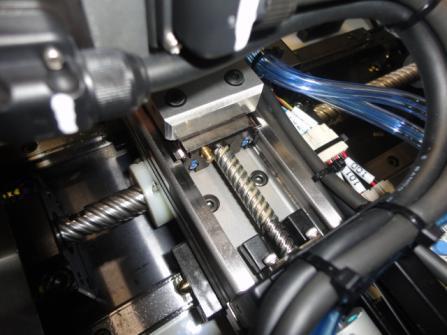
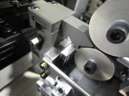


95 INSPECTION AND MAINTENANCE Prefeed Feed Cut / Strip XY Unit XY Unit 4 5 XY Unit No.1 Clamp No.2 Clamp No.2 Clamp Eject Wire receive Eject clamp Clamp
 is not possible: Guide section Put grease in the groove of LM rail and move nut block for 2 ~ 3 times. Wipe off excess grease. Repeat it for 2 ~ 3 times.")
96 INSPECTION AND MAINTENANCE <How to Lubricate> Use grease gun where there are grease nipples. *Some sections cannot be lubricated by Grease gun. 1:Lubricate with grease gun from grease nipple. 2:When (1) is not possible: Guide section Put grease in the groove of LM rail and move nut block for 2 ~ 3 times. Wipe off excess grease. Repeat it for 2 ~ 3 times. *Make sure there are no foreign objects are mixed. Screw section Put grease on Ball screw shaft and move nut block for 2 ~ 3 times. Wipe off excess grease. Repeat it for 2 ~ 3 times. *Make sure there are no foreign objects are mixed. Put grease with brush on LM Guide rail and ball screw shaft. Where you cannot put grease such as Link section, use Pervious ness lubricating oil that is not too loose 2 ~ 3 times a week. Do not put too much. 93

97 INSPECTION AND MAINTENANCE 3. Removing cut chips Remove strip chips and carrier chips in trash can after operation. Use vacuum cleaner for chips on machine main base. Use brush to clean narrow place such as between units. 4. Compressed air This machine has solenoid and cylinder that uses compressed air to run. Adjust filter regulator for the pressure to be 0.5 MPa. Refer to attached manual for pressure setting. Compressed air is a drive source of this machine. Use of compressed air contaminated with water or other impurities may lead to a malfunction of the machine. Always use clean compressed air. If air quality is poor, install an air dryer or the link to correct this problem. Drain residue from the filter regulator prior to everyday operation. Filter regulator Pressure switch setting Ball valve Pressure gauge Pressure switch Drain knob (turn) 5. Routine cleaning Carry out cleaning every day as shown below. Constantly remove cut chips (wire, strip chip and carrier chip) and perform cleaning after operation. (1) If cut chips are blown by air, they go into the working part of machine, it becomes a defect of operation and the cause of failure. Clean the cut chips using a vacuum, a cleaner, etc. (2) Clean the machine regularly. It will lead to make good working conditions, enhance the work efficiency and prolong the machine life. 94
Opera ons & Parts Manual VersaClipper 3100
 Opera ons & Parts Manual VersaClipper 3100 Heavy Duty Servo Driven & Computer Controlled Fully Automa c and Highly Versa le Clip A aching Machine Model #3100 Serial # 1 Revised 09/21/17 Table of Contents
TERMINATOR User Manual
 TERMINATOR User Manual TERMINATOR User Manual Table of Contents Section Page 1 2 3 4 5 6 7 8 9 10 11 12 13 14 15 16 17 18 19 20 21 Introduction Safety Precautions Features and Benefits Overview of the
Combined Ventilation Controller RVWS-T-224HA
 Combined Ventilation Controller RVWS-T-224HA 8-stage Control for Power/Natural Applications 2 variable speed stages, 2 curtain winch stages, 2 fixed speed ventilation stages, 1 thermo/mister cycle stage
CONTROL FEATURES AVAILABLE OPTIONS
 Vari Speed A2000 TABLE OF CONTENTS Control Features Options Application Data Operating Condition s Control Ratings Chart Mounting Dimensions Installation and Wiring Typical Wiring Diagram Schematic (Block
CBM-105FN/FP Circuit Board
 CBM-105FN/FP Circuit Board Features Adjustable acceleration and deceleration time (0 to 2.5s) Stable speed operation Manual or automatic recovery of the thermal overload device One (1) rotary switch to
SYSTEM 4000 TRIMMER DBM-400T
 SYSTEM 4000 TRIMMER Instruction Manual DUPLO CORPORATION INTRODUCTION Thank you for your purchase. To ensure correct usage, please read this instruction manual thoroughly, especially the section Safety
FD 120 Card Cutter MAINTENANCE MANUAL. MyBinding.com 5500 NE Moore Court Hillsboro, OR Toll Free: Local: /2011
 FD 120 Card Cutter 5/2011 MAINTENANCE MANUAL SAFETY PRECAUTIONS Always observe the cautions and warnings given below to prevent personal injury or property damage. The degree of danger and damage that
User Manual. Solar Charge Controller 3KW
 User Manual Solar Charge Controller 3KW 1 CONTENTS 1 ABOUT THIS MANUAL... 3 1.1 Purpose... 3 1.2 Scope... 3 1.3 SAFETY INSTRUCTIONS... 3 2 INTRODUCTION... 4 2.1 Features... 4 2.2 Product Overview... 5
GENERAL INFORMATION. H-1649, H-1650, H-1651 H-1653, H-1654 Easy-Count. uline.com. that may hurt accuracy:
 π H-1649, H-1650, H-1651 H-1653, H-1654 Easy-Count counting scale 1-800-295-5510 uline.com 1-800-295-5510 GENERAL INFORMATION Avoid placing the scale in locations that may hurt accuracy: 1. Temperature
PREMIUM QUALITY MANUFACTURING OF CRIMP CONNECTIONS AMP 3K, 5K, GII AND GII + TERMINATORS
 PREMIUM QUALITY MANUFACTURING OF CRIMP CONNECTIONS AMP 3K, 5K, GII AND GII + TERMINATORS AMP-O-LECTRIC GII Terminator Safety first. Improved guarding on the Model G II terminator provides open access for
Setup and Programming Manual
 Microprocessor and Handy Terminal Setup and Programming Manual Versions U04 to U19 for Sliding Door Systems P/N 159000 Rev 7-2-07 The manufacturer, NABCO Entrances, Inc. suggests that this manual be given
JTEKT Toyoda Americas Corporation
 JTEKT Toyoda Americas Corporation 316 W. University Drive, Arlington Heights, IL 60004 Toll Free: 800-257-2985 Main: 847-253-0340 Fax: 847-253-0540 www.toyoda.com JTEKT Toyoda Americas Corporation Designed
PREMIUM QUALITY MANUFACTURING OF CRIMP CONNECTIONS AMP 3K, 5K, GII AND GII + TERMINATORS
 PREMIUM QUALITY MANUFACTURING OF CRIMP CONNECTIONS AMP 3K, 5K, GII AND GII + TERMINATORS AMP-O-LECTRIC GII Terminator Safety first. Improved guarding on the Model G II terminator provides open access for
Cat. No. I526-E1-1 USER S MANUAL 3G3IV-PLKEB2 /4. Braking Resistor Units 3G3IV-PCDBR2 B/4 B. Braking Units
 Cat. No. I526-E1-1 USER S MANUAL 3G3IV-PLKEB2 /4 Braking Resistor Units 3G3IV-PCDBR2 B/4 B Braking Units Thank you for choosing an OMRON Braking Resistor Unit and Braking Unit. Proper use and handling
SE-600-P Eco-Series. Operation & Parts Manual
 SE-600-P Eco-Series Operation & Parts Manual SE 600 PC & PS SERIES OWNERS MANUAL Table of Contents 1. Set-up instructions 2. Bridge-Tramming Procedure 3. Operation instructions 4. Cleaning 5. Troubleshooting
User Manual Solar Charge Controller 3KW
 User Manual Solar Charge Controller 3KW Version: 1.3 CONTENTS 1 ABOUT THIS MANUAL... 1 1.1 Purpose... 1 1.2 Scope... 1 1.3 SAFETY INSTRUCTIONS... 1 2 INTRODUCTION... 2 2.1 Features... 2 2.2 Product Overview...
Gate & Door Controller with LCD and Intelligent Technology
 2nd Edition Gate & Door Controller with LCD and Intelligent Technology 24Sv1 and 12Sv1 Motor Controllers Setup and Technical information for single motor controller for gates & doors Includes latest Intelligent
Andatech SOBERPOINT 3. Wall Mounted Breathalyser USER S MANUAL
 Andatech SOBERPOINT 3 Wall Mounted Breathalyser USER S MANUAL Thank you for purchasing an Andatech Soberpoint 3 breathalyser. The Andatech Soberpoint 3 is a Fuel Sensor type coin- or buttonoperated breathalyser.
OLYMPIAN MODEL 740 Operation and Service Manual
 OLYMPIAN MODEL 740 Operation and Service Manual P/N 133911-102 FCI MANUAL P/N 133865-001 Data herein has been verified and validated and believed adequate for the intended use. If the machine or procedures
Maximiser Progressive Controller
 Maximiser Progressive Controller Street & Race Model Owner's Manual 44 (0) 01302 834343 www.noswizard.com Introduction Congratulations on purchasing the Maximiser for the ultimate in progressive nitrous
World Leaders in Diesel Fuel Injection Test Equipment. IFT-c. Injector Function Tester Controller. Operating and Servicing Manual
 World Leaders in Diesel Fuel Injection Test Equipment. IFT-c Injector Function Tester Controller Operating and Servicing Manual HL048 (EN) Issue 4, H1852, August 2011 HARTRIDGE LIMITED IFT-c Operating
Terminal Assembly Machine
 1996 Instruction/Service Manual Terminal Assembly Machine Acme Manufacturing Inc. #J9876 Built by: For: The Wiley Company ACME Manufacturing, Inc. 2000 Coyote Lane Roadrunner, MN 55122 (612) 555-1234 (612)
CD100 Series. Operators Manual SINGLE COLUMN CARD DISPENSER
 CD100 Series SINGLE COLUMN CARD DISPENSER Operators Manual Contents 1 Specifications...1 2 Installation...2 2.1 Unpacking and inspection...2 2.2 Installation...2 2.3 Electrical Connections...2 2.4 Initial
ACROMARK HOT STAMP PRESS
 ACROMARK HOT STAMP PRESS FACE PANEL CONTROLS AND THEIR FUNCTION (Manual Presses/ Mitsubishi controls with F920-GOT Displays) 1. MAIN POWER SWITCH - Key pad will illuminate and machine becomes functional
ATS-9600/9700 TABBER/LABELER
 ATS-9600/9700 TABBER/LABELER INSTALLATION AND OPERATING INSTRUCTIONS SAFETY PRECAUTIONS THIS EQUIPMENT PRESENTS NO PROBLEM WHEN USED PROPERLY. HOWEVER, CERTAIN SAFETY RULES SHOULD BE OBSERVED WHEN OPERATING
TA-05/C. Instruction and Operation Manual. valid for art.-no.: F-TA-05/C-ISO. (start at modification No. 1601)
") Instruction and Operation Manual valid for art.-no.: 10091 F-TA-05/C-ISO (start at modification No. 1601) valid for art.-no.: 10092 F-TA-05/C-Sh (start at modification No. 1601) CAUTION: As with any form
Instruction and Operation Manual valid for art.-no.: 10091 F-TA-05/C-ISO (start at modification No. 1601) valid for art.-no.: 10092 F-TA-05/C-Sh (start at modification No. 1601) CAUTION: As with any form
RENA AF371Feeder Operating Manual. Feeder. Operating Manual. Manual Part #: M AF371 Operations Rev
 Manual Part #: M-3022 Feeder AF371 Operations Rev. 3-16-04 1 RENA AF371 Feeder YOUR RENA AF371 IS DISTRIBUTED BY RENA SYSTEMS INC. SERVICE AND SUPPORT FOR THIS PRODUCT IS PROVIDED BY YOUR RENA DEALER.
Barrier Gate Manual. (DZX2.1 Control Board) (The third version) (Pictures for reference only, the product prevail in kind)
 (The third version) (Pictures for reference only, the product prevail in kind)") Barrier Gate Manual (DZX2. Control Board) (The third version) (Pictures for reference only, the product prevail in kind) Contents. Brief Introduction... 2. Functions and Features... 3. Technical Data...2
Barrier Gate Manual (DZX2. Control Board) (The third version) (Pictures for reference only, the product prevail in kind) Contents. Brief Introduction... 2. Functions and Features... 3. Technical Data...2
Emergency lighting units EM powerled
 BASIC FX 80 W Combined emergency lighting LED Driver Product description Fixed-output LED Driver for mains operation with integrated Simple CORRIDOR FUNCTION (CF) Emergency lighting LED Driver with manual
Bench Top Tube Bender
 Bench Top Tube er User s Manual Electric and manual units s fractional and metric tubing CE compliant 2 Bench Top er User s Manual Contents Safety Instructions... 2 Technical Data... 2 Tubing Data... 3
OPERATION MANUAL Electric Wire Wrapper TDWW501B
 OPERATION MANUAL Electric Wire Wrapper TDWW501B 4270 Airborn Drive Addison, Texas 75001 USA t. 972.248.1999 f. 972.248.1991 info@startinternational.com www.startinternational.com INTRODUCTION Thank you
IMPORTANT! DO NOT THROW AWAY THE SHIPPING CARTON AND PACKING MATERIAL
 Operator s Manual IMPORTANT! DO NOT THROW AWAY THE SHIPPING CARTON AND PACKING MATERIAL ii Table of Contents Operator Safety... 1 Introduction... 2 Unpacking and Setup... 3 Unpacking... 3 Setup... 4 ROCKET
OPERATING INSTRUCTION MANUAL QUICK-KON AUTOMATED CRIMPING SYSTEM for Catalog Number: TNB170-ELECDIE TABLE OF CONTENTS
 OPERATING INSTRUCTION MANUAL QUICK-KON AUTOMATED CRIMPING SYSTEM for Catalog Number: TNB170-ELECDIE IMPORTANT: Read and understand all of the instructions and safety information in this manual before operating
Automatic Sliding Door Retrofit Drive Assembly. Installation Manual DoorControlsUSA.com
 Automatic Sliding Door Retrofit Drive Assembly Installation Manual 800-437-3667 DoorControlsUSA.com TABLE OF CONTENTS pg. 1. COMPONENTS 2 2. HEADER PREPARATION 2 3. DOOR PREPARATION 2 4. MOTOR AND CONTROLLER
5001TCP SPEED CONTROLLER
 VARIABLE SPEED DRIVE CONTROLLER INSTALLATION AND SETTING UP MANUAL 5001TCP SPEED CONTROLLER With PC101 Torque Limit Control WARNING Disconnect all incoming power before working on this equipment. Follow
How to operate TBC-555L
 TBC-555L. How to operate TBC-555L TBC-555L 1. An example (Cutting length : 70mm, Cutting quantity : 120 pcs) Turn on the POWER SW. Set cutting length. (Press the following buttons in order.) Set cutting
MB A 12V/24V DC PROGRAMMABLE DUAL BATTERY ISOLATOR
 MB-3688 120A 12V/24V DC PROGRAMMABLE DUAL BATTERY ISOLATOR User Manual Warning and Precautions MB-3688 is built with corrosion resistant material and the main electronic assembly is well sealed inside
Hand pump PUMP1000-4L-CONTROL. User manual
 Hand pump PUMP1000-4L-CONTROL User manual Safety guidelines and symbols High product safety Follow instructions Definition of guidelines and symbols Warning Caution Our products correspond to the current
BRSDRIVE ITT. Goulds Pumps. S-Drive. Simplex Variable Speed Submersible Pump Controller. Engineered for life
 ITT BRSDRIVE Goulds Pumps Simplex Variable Speed Submersible Pump Controller C U L US Engineered for life Do you want to Simplify your Commercial Pumping System? Goulds Pumps S-Drive variable speed, constant
YSmart Technology Co., Ltd. User Manual. GTI Grid Series. GTI Series Inverters for Grid-connected PV system
 YSmart Technology Co., Ltd. User Manual Contact Us Address: No. 30 XinFeng Road,Potoubei Village,Ailian Town,Longgang Dist, Shenzhen 51872,P.R. China Tel: (86)755-85232255 Fax: (86)755-85232255 Email :
Cut-to-size saw fh6 430 / 160 Auto load
 Cut-to-size saw fh6 430 / 160 Auto load Automatic infeed Drawing number: fh6 430/160 Machine number: Delivery date: TBD TBD Project based requirements, machine type fh6 Name: Information Working pressure:
17429X.00 SERIES MODELS:
 LEESON ELECTRIC MOTORS, GEARMOTORS AND DRIVES R User s Manual 17429X.00 SERIES MODELS: 174298.00 174299.00 PWM REGENERATIVE DC TO DC DRIVES II Table of Contents 17429X.00 Drives...............................................................
Document number: BL-2330 (V1.0) SERVO DRIVE UNIT. MAINTENANCE MANUAL BLIV-D Type A (1st Edition) Pub. No E (SE R1) Apr.
 SERVO DRIVE UNIT. MAINTENANCE MANUAL BLIV-D Type A (1st Edition) Pub. No E (SE R1) Apr.") Document number: SERVO DRIVE UNIT MAINTENANCE MANUAL BLIV-D Type A (1st Edition) Pub. No. 5552-E (SE41-072-R1) Apr. 2008 LIST OF PUBLICATIONS LIST OF PUBLICATIONS Version Date of revision Description Applicable
Document number: SERVO DRIVE UNIT MAINTENANCE MANUAL BLIV-D Type A (1st Edition) Pub. No. 5552-E (SE41-072-R1) Apr. 2008 LIST OF PUBLICATIONS LIST OF PUBLICATIONS Version Date of revision Description Applicable
OPERATOR TROUBLESHOOTING GUIDE
 OPERATOR TROUBLESHOOTING GUIDE ABOUT THE TROUBLESHOOTING GUIDE This document is provided for the use of qualified operator installers. The installer should familiarize themselves with this guide Options
SERVICE MANUAL BAS-311H. Please read this manual before making any adjustments. DIRECT DRIVE PROGRAMMABLE ELECTRONIC PATTERN SEWER
 SERVICE MANUAL Please read this manual before making any adjustments. DIRECT DRIVE PROGRAMMABLE ELECTRONIC PATTERN SEWER This service manual is intended for ; be sure to read the instruction manual before
Section 18: Fuses, Heaters, Parameters
 Section 18: Fuses, Heaters, Parameters March 2003 Section 18: Fuses, Heaters, Parameters 639 640 Section 18: Fuses, Heaters, Parameters March 2003 March 2003 Section 18: Fuses, Heaters, Parameters 641
HYBRID HYDRAULIC O OIL COOLING EQUIPMENT O-1
 HYBRID HYDRAULIC O OIL COOLING EQUIPMENT O-1 List of Hybrid Unit Models Various specifications for each model. DAIKIN s lineup provides a variety of functions and capacities depending on the machine type.
TOWER MAXI T SINGLE CONVERSION ON LINE UPS SYSTEMS
 INSTRUCTION MANUAL TOWER MAXI T SINGLE CONVERSION ON LINE UPS SYSTEMS September 2000 TOWER UPS DISTRIBUTION (PTY) LTD 1 1. INTRODUCTION T A B L E O F C O N T E N T S 1.1 General Description... 3 1.2 Features...
Weighing System CALIBRATOR ZURF
 Weighing System CALIBRATOR ZURF Content First necessary steps p. 2 General information p. 3 Fault CALIBRATUR ZURF p. 5 Fault Adjusting actuator p. 7 Fault Trend actuator p. 8 Fault The weight p. 9 Fault
ADJUSTABLE FREQUENCY CONTROLS SENSORLESS VECTOR CONTROL. Dual Rating. Technologies Inc. mgitech.com NRTL/C CERTIFIED
 ADJUSTABLE FREQUENCY CONTROLS SENSORLESS VECTOR CONTROL Dual Rating NRTL/C CERTIFIED Technologies Inc. mgitech.com Sensor/Sensorless Vector Control Dual current rated for constant and variable torque Auto
HYDROVANE ROTARY VANE COMPRESSOR WITH REGULATED SPEED - THE 'RS' RANGE (7kW - 75kW)
") HYDROVANE ROTARY VANE COMPRESSOR WITH REGULATED SPEED - THE 'RS' RANGE (7kW - 75kW) Performance and Technical Data. Please refer to the final 2 pages of this document. Hydrovane are pleased to announce
HYDROVANE ROTARY VANE COMPRESSOR WITH REGULATED SPEED - THE 'RS' RANGE (7kW - 75kW) Performance and Technical Data. Please refer to the final 2 pages of this document. Hydrovane are pleased to announce
Table of Contents. AMO series quantitative pressured centralized lubricating system 1. Illustration of AMO motor driven lubricating system 1
 Table of Contents AMO series quantitative pressured centralized lubricating system 1 Illustration of AMO motor driven lubricating system 1 AMO motor driven thin oil lubricating pump MO type pressured thin
PHASE CONVERTERS OPERATING & MAINTENANCE INSTRUCTIONS. MODEL NO: PC40 and PC60. PART Nos:
 PHASE CONVERTERS MODEL NO: PC40 and PC60 MODEL PART No: NO: 6012805 PC20 and PC40 6012810 PC60 PART Nos: 6012800 6012805 6012810 OPERATING & MAINTENANCE INSTRUCTIONS 0107 Specifications PC20 PC40 PC60
J1000 D E F I 1000 J1000 J1000 J1000 J1000
 Compact Inverter SERIES J1000 GB D E F I 1000 J1000 J1000 J1000 J1000 The J-Type YASKAWA Inverter Drive Technology Contents Page 2 Experience & Innovation A leader in Inverter Drives technology Page 3
***Before starting : view the Virtual tour located at c:/programs/msoffice/powerpointviewer And carry out the tutorials in the manuals supplied***
 Fatigue Machine Turn on Chiller isolator to machine (Located behind Torque/ Tension Machine) Turn on main isolator to machine Reset Isolator switch and wait for all LEDs to go from red to off LED s Starter
Instruction Manual LAMI CORPORATION INC.
 Instruction Manual LAMI CORPORATION INC. Preface Thank you for purchasing our. This Instruction Manual (document) includes details for safe use of this product. Please read this document thoroughly before
How to operate TBC-50LH/AIR
 How to operate TBC-50LH/AIR 1. An example (Cutting length : 70mm, Cutting quantity : 120 pcs) Turn on the POWER SW. Set the temperature.(it is normally used at 250 ~350 C. About 5 minutes after turn-on,
AeroVironment Universal Solar Pump Controllers
 AeroVironment Universal Solar Pump Controllers (Installer s business information to be affixed here.) User Manual Models: USPC-2000 (AV Part Number 03747-001 Rev. D) USPC-5000 (AV Part Number 03747-002
AS Series. 4.0 g. Weight: Approx. 27% lighter. Flow Rate Reproducibility. Larger Knob. Easy Identification of Product Type. 5.5 g.
 Speed Controller with One-touch Fittings In-line In-line Type y Easo t use RoHS Brass Stainless steel Reduces flow setting time! Push-lock type Knob O.D.: Almost doubled! Easy to lock ø9.4 Unlock ø5 Lock
High Accuracy Eddy Current Type Displacement Sensor GP-A SERIES. Resolution 0.04 % F.S., Linearity ±0.5 % F.S., IP67G environment resistance
 11 High Accuracy ddy Current Type Sensor SRIS Related Information General terms and conditions... F-7 Glossary of terms... P.1493 Sensor selection guide... P.1055~ General precautions... P.1501 PHOTO PHOTO
TOWA SEIDEN INDUSTRIAL CO., LTD.
 INSTRUCTION MANUAL SOUNDING LEVEL METER MODEL: TLX-120AP/200AP Meanings of indications for safety used in this Instruction Manual are as follows. WARNING: Indicates that improper handling assumes the risk
NANOPAC-300 & 500 Power Supply. Instruction manual NANOPAC-300 & NANOPAC-500
 NANOPAC-300 & 500 Power Supply Instruction manual NANOPAC-300 & NANOPAC-500 Version 01C Feb 5th, 2014 1 Packing list NANOPAC-300 or 500-1x NANOPAC-300 Power Supply or NANOPAC-500-1x Power Cord - 1x Instruction
HD 7700 Setup & Operator Manual
 HD 7700 Setup & Operator Manual Issue 1 December, 01 Performance Design Inc. The Heavy Duty Ultima (HD 7700) electric punch has been designed to punch most any job that may pass through your bindery or
Pressure sensor with built-in amplification and temperature compensation circuit
 sensor with built-in amplification and temperature compensation circuit PS-A PRESSURE SENSOR (built-in amplification and temperature compensating circuit) NEW FEATURES 1. Contains built-in amplification
ACCESSORY KIT INSTALLATION INSTRUCTIONS
 ACCESSORY KIT INSTALLATION INSTRUCTIONS Low Ambient Accessory For Air Cooled Split-System Air Conditioners YD360/480/600, YJ-30/-40/-50 and J30/40/50 YD Models 642546-UAI-A-080 GENERAL Standard operation
POWER REGULATOR LD -40PSU
 JZ99D4121A AMPIFIRE AMPIFIRE TYPE D-4PSU ZJ-46A ISTRUCTI MAUA Manual number JZ99D4121 Sub number A Date of preparation ov. 2 Thoroughly read this instruction manual, and then use the unit correctly. Especially,
CENTROIDTM. AC Brushless Drive. Product Spec Sheet
 4 Axis, up to 2 KW motors Brake Output for each axis Overtemp and Overcurrent Protection All-software Configuration Self-cooled Fiber Optic Control CENTROIDTM AC Brushless Drive Product Spec Sheet AC Brushless
Internet For latest information, PDF catalogs and operation manuals
 EcoRich Features Achieves a % or greater energy saving (in the pressure retained mode, comparison with Daikin products) Drastic energy savings are realized by reducing the motor rotation speed in pressure
PRODUCT MANUAL OPERATOR S MANUAL VEHICLE SPEED CONTROL SYSTEM TOYOTA SPECIAL DESIGN
 PRODUCT MANUAL OPERATOR S MANUAL TOYOTA SPECIAL DESIGN VEHICLE SPEED CONTROL SYSTEM WARNING This manual describes how to handle the Vehicle Speed Control System. For other features, refer to Operator s
DPC-100 Series INSTRUCTION MANUAL WIRING I/O CIRCUIT DIAGRAMS PART DESCRIPTION
 Sensor INSTRUCTI MANUAL Head Separated Digital Sensor Controller DPC-1 Series MJE-DPC1 No.7-98V Thank you very much for using SUNX products. Please read this Instruction Manual carefully and thoroughly
MULTI FUNCTIONAL COUNT CHECKER MODEL Poka Patrol CNA-4mk3
 MULTI FUNCTIONAL COUNT CHECKER MODEL Poka Patrol CNA-4mk3 OPERATING INSTRUCTION Poka Patrol CNA-4mk3 Poka Patrol CNA-4mk3 To use this product properly and safely, please read this manual carefully before
CRANE FUNCTION MANUAL. FR-A (0.4K) to 04750(90K)-CRN FR-A (0.4K) to 06830(280K)-CRN FR-A (315K) to 12120(500K)-CRN
 to 04750(90K)-CRN FR-A (0.4K) to 06830(280K)-CRN FR-A (315K) to 12120(500K)-CRN") INVERTER CRANE FUNCTI MANUAL FR-A820-00046(0.4K) to 04750(90K)-CRN FR-A840-00023(0.4K) to 06830(280K)-CRN FR-A842-07700(315K) to 12120(500K)-CRN Crane Function The FR-A800-CRN has dedicated functions for
INVERTER CRANE FUNCTI MANUAL FR-A820-00046(0.4K) to 04750(90K)-CRN FR-A840-00023(0.4K) to 06830(280K)-CRN FR-A842-07700(315K) to 12120(500K)-CRN Crane Function The FR-A800-CRN has dedicated functions for
User Manual. Hydro Charger and Solar Hybrid Charge Controller
 User Manual Hydro Charger and Solar Hybrid Charge Controller Please read this manual very carefully. Failures may result in serious injury and permanent damage to the hybrid charge controller and attached
ION JET NOZZLE NIH-55
 ION JET NOZZLE NIH-55 INSTRUCTION MANUAL - Read this instruction manual and make sure you thoroughly understand its contents before attempting to operate, inspect or service this product. - The users and
Automated socks packaging machine PS-1
 English Manual Automated socks packaging machine PS-1 Contents 1. Introduction 2. Important safety instructions 3. PS-1 4. Installation of air supply 5. SwifTach Power Unit (SPU) module 6. Operations 7.
Operating Instructions Type MPT 53
 Operating Instructions www.turnstiles.us Type MPT 53 Contents 1. Delivery... 2 2. Safety...3-4 3 Description and operation... 5 4. Technical Data 6 5. oundation...6-9 6. Assembly and installation...10-13
Transmitter CSA-591 Instruction Manual
 Transmitter CSA-591 Instruction Manual EN294-1141-F FOREWORD Thank you very much for your purchasing our Transmitter CSA 591. This manual explains installation procedures and connecting method and also
ELECTRONIC CONTROL ACTUATOR
 ELECTRONIC CONTROL ACTUATOR Nucom Series LINEAR TYPE Nucom L25 Nucom L50 OPERATION MANUAL Koei Industry Co., Ltd. FOR YOUR SAFETY In order for better and safety use of the product for a long period, please
R & D SPECIALTIES ROTROL I USER'S MANUAL
 R & D SPECIALTIES ROTROL I USER'S MANUAL TABLE OF CONTENTS INTRODUCTION...2 SPECIFICATIONS...2 CONTROLS AND INDICATORS...3 TIME DELAYS...4 INSTALLATION...5 SYSTEM OPERATION...9 TROUBLESHOOTING...13 OPTIONAL
IB INTERNATIONAL Pty Ltd OCMIS INSTRUCTION MANUAL AQUA SYSTEM 3
 IB INTERNATIONAL Pty Ltd OCMIS INSTRUCTION MANUAL AQUA SYSTEM 3 Australian Importer and Distributor - IB INTERNATIONAL Pty Ltd PO Box 5481, Manly Qld 4179 Telephone: 61 7 3348 83 Facsimile: 61 7 3348 89,
LIPPERTCOMPONENTS, INC.
 LIPPERTCOMPONENTS, INC. SCHWINTEK INWALL SLIDEOUT SYSTEM OPERATION AND SERVICE MANUAL Contents I. Controls 1-1 System components 1 1-1A versions C1 & C2 2 1-2 Motor wiring harness connections 3 1-3 Extend
ROGOWSKI LEAK METER MODEL RLM-1
 ROGOWSKI LEAK METER MODEL RLM-1 INSTRUCTION MANUAL Thank you very much for selecting our model RLM-1 Flexible Leakage Current Meter. This model is complex instrument and employ a very reliable mechanical/electronic
User s Manual. Automatic Switch-Mode Battery Charger
 User s Manual Automatic Switch-Mode Battery Charger IMPORTANT Read, understand, and follow these safety rules and operating instructions before using this battery charger. Only authorized and trained service
Parker AC10 Frequency Inverter (to 22kW) Easy Start Guide
 Easy Start Guide") Parker AC10 Frequency Inverter (to 22kW) Easy Start Guide CAUTION: 1)Do not re-set while the motor is rotating 2)Perform parts replacement after discharge is finished 3)Do not connect output terminals
Parker AC10 Frequency Inverter (to 22kW) Easy Start Guide CAUTION: 1)Do not re-set while the motor is rotating 2)Perform parts replacement after discharge is finished 3)Do not connect output terminals
5001TCP SPEED CONTROLLER
 INSTALLATION AND SETTING UP MANUAL 5001TCP SPEED CONTROLLER WARNING Disconnect all incoming power before working on this equipment. Follow power lockout procedures. Use extreme caution around electrical
OPERATING INSTRUCTIONS AutoForce
 OPERATING INSTRUCTIONS AutoForce TRANSLATION OF THE ORIGINAL OPERATING INSTRUCTIONS READ CAREFULLY PRIOR TO STARTING UP! KEEP OPERATING INSTRUCTIONS IN A SAFE PLACE! ART.: ISSUE: 8072 0213 02/2017 - Translation
Emergency lighting units EM powerled
 BASIC FX SR 50 W Combined emergency lighting LED Driver Product description Independent fixed output LED Driver for mains operation with integrated Simple CORRIDOR FUNCTION (CF) Emergency lighting function
UP100AC INSTRUCTION MANUAL
 UP100AC AC/DC Charger INSTRUCTION MANUAL 100W 10A TABLE OF CONTENTS Introduction... 2 Special Features... 4 Warning and Safety Notes... 6 Lithium Battery Connection Diagram... 10 Operation Diagram - Homepage...
DIGITAL CLAMP TESTER MODEL HCL-5000D
 DIGITAL CLAMP TESTER MODEL HCL-5000D INSTRUCTION MANUAL Thank you very much for selecting our digital clamp tester model HCL-5000D for AC line current in Hi-voltage circuit. This model is complex instrument
EX Series. Electric Actuators for Ball and Butterfly Valves
 EX Series Electric Actuators for Ball and Butterfly Valves Next Generation Electrical Actuator Realization of Upgraded General-Purpose Actuators The modularization and the adoption of common parts have
MICRO EJECTORS. Micro ejector single unit (without solenoid valve) ME. Micro ejector with solenoid valve DC24V. Block-off plate ME MA-BP
 ME. Micro ejector with solenoid valve DC24V. Block-off plate ME MA-BP") Micro Ejector Order Codes Manifold Order Codes Micro ejector single unit (without solenoid valve) ME Body model nozzle diameter : Maximum flow rate on vacuum side 03 0.3 : 3.0R/min. [0.012in., 0.106ft.
Micro Ejector Order Codes Manifold Order Codes Micro ejector single unit (without solenoid valve) ME Body model nozzle diameter : Maximum flow rate on vacuum side 03 0.3 : 3.0R/min. [0.012in., 0.106ft.
POWER SUPPLY MODEL XP-800. TWO AC VARIABLE VOLTAGES; 0-120V and 7A, PLUS UP TO 10A. Instruction Manual. Elenco Electronics, Inc.
 POWER SUPPLY MODEL XP-800 TWO AC VARIABLE VOLTAGES; 0-120V and 0-40V @ 7A, PLUS 0-28VDC @ UP TO 10A Instruction Manual Elenco Electronics, Inc. Copyright 1991 Elenco Electronics, Inc. Revised 2002 REV-I
Yaskawa AC Drive L1000A Supplement to the L1000A Technical Manual No. SIEP C , SIEP C , and SIEP C
 Yaskawa AC Drive L1000A Supplement to the L1000A Technical Manual No. SIEP C710616 32, SIEP C710616 33, and SIEP C710616 38 Introduction This supplement to the L1000A Technical Manual describes features
M u l t i P o w e r. CM MultiPower. Installation and Operating Manual
 M u l t i P o w e r CM MultiPower Installation and Operating Manual Index 1. Introduction of the 4HS submersible pumps range... 3 2. Safety Instructions... 4 3. CM MP installation... 5 3.1 Electric wiring...
320iB Mark II/436LiB, 525iB/536LiB, 530iBX
 540-001 - 04.10.2018 Workshop manual 320iB Mark II/436LiB, 525iB/536LiB, 530iBX From S/N 20180100002 English Contents 1 Introduction 1.1 Document description... 3 1.2 Target group...3 1.3 Revisions...3
BSPDDRIVE ITT. Goulds Pumps. Aquavar SPD (Single Pump Drive) Simplex Variable Speed Pump Controller
 Simplex Variable Speed Pump Controller") ITT BSPDDRIVE Goulds Pumps Aquavar SPD (Single Pump Drive) C U L US Do you want to Simplify your Commercial Pumping System? Goulds Pumps SPD variable speed, constant pressure pump controller is designed
ITT BSPDDRIVE Goulds Pumps Aquavar SPD (Single Pump Drive) C U L US Do you want to Simplify your Commercial Pumping System? Goulds Pumps SPD variable speed, constant pressure pump controller is designed
PREPOINT CHAMFER GRINDER MODEL Section 1. Set up and operation
 PREPOINT CHAMFER GRINDER MODEL 6-94 Set up and operation Section 1 1. Installation of the proper size collet. This machine used a 5-C style collet. This can be changed by loosening of he set screw located
UNIVERSAL AUTOMATIC MACHINE FOR WINDING STIFF AND ELASTIC RIBBON ONTO CORES, FLANGED CORES, SPOOLS AND FLAT PACKS
 UNIVERSAL AUTOMATIC MACHINE FOR WINDING STIFF AND ELASTIC RIBBON ONTO CORES, FLANGED CORES, SPOOLS AND FLAT PACKS Fully automatic, extremely versatile machine designed to produce a variety of different
Installation Instructions
 CRLOWAMB039A00 CRLOWAMB040A00 CRTRXKIT002A00 ACCESSORY MOTORMASTER I HEAD PRESSURE CONTROL KIT 12.5 TON HEAT PUMP Installation Instructions TABLE OF CONTENTS PACKAGE CONTENTS... 1 PRODUCT USAGE... 2 SAFETY
Standard PS-P61 Punch Stapler
 Standard PS-P61 Punch Stapler Service Manual Provided By http://www.mybinding.com http://www.mybindingblog.com SERVICE MANUAL PS-P61 Punch Staple 510 Kuze Ooyabu-cho Minami-ku, Kyoto 601-8206, Japan Phone:+81-75-934-6700,