PRECISION MICROSCOPES
|
|
|
- Claude Ambrose Garrison
- 5 years ago
- Views:
Transcription

1 SEILER 202/402 Owner s Manual PRECISION MICROSCOPES A Division of Seiler Instrument Company PRECISION MICROSCOPES A Division of Seiler Instrument Company
2
3 microscope beam split-port and wedge the orientation bolt of the beam split-port into the orientation groove of the CCD adapter [B3]. (There are three grooves on the plane. Select one according to your needs.) Screw down the screw flange [B2] on the top of the adapter. (5) Screw off the lens and screw flange of the CCD [B8] and keep them well. Screw the CCD connector [B6] into the CCD lens and tighten it. (6) Screw down the CCD with the CCD adapter [B3]. (7) Connect the power plug to the appointed adapter [B3]. (8) Connect one end of the video frequency wire to the CCD signal fan-out. The other end should be connected to the Video In port of the monitor or video camera. Switch on the power after all have been done. Observe the image on the monitor and rotate the focus-adjusting ring [B4] to make the image clear. Pay attention to the orientation of the image. Rotate the CCD out by the inches until the image s orientation is right, if it is declining. Screw down the screw flange [B5] to lock it. (9) Fix the geminate ocular drawtubes to the beam splitter [B1] and screw the inner hexagonal tightening bolt [A3] by the 2mm inner hexagram screw drive. (Fig. 6) ATTENTION: After the above assembly, the dynamic balance of the second arm should be adjusted. Deploy the second horizontally, and drag the microscope up and down, and then compare the resistance between upward movement and downward movement. If the resistance of upward movement is greater, rotate the balance adjustment knob [10] counter-clockwise. If the resistance of downward movement is greater, then rotate the balance adjustment knob clockwise. Do this repeatedly until the resistance of both movements are equivalent. The the small arm may stay steady in any position of ± 20º relative to horizontal line. ATTENTION: Every time before adjusting the balance adjustment knob [10], the second arm should be pushed to the utmost peak in order to decrease the resistance against the rotation adjustment of the balance adjustment knob. TABLE OF CONTENTS 1 Features and specifications Features Specifications 1 2 The name and use of components 3 3 Assembly Assembly of stand pillar Assembly of light source box Assembly of microscope Assembly of manipulating handle Assembly of fiber optics 6 4 Preparation for use 6 5 Use of instrument Use of foot control switch Installation and adjustment before using Adjustment during use Movement and storage after using 9 6 Maintenance Replacing of the consumable parts Replacing the spare bulbs Replacing the fuses Cleaning and sterilization Trouble-shooting guide Order consumable parts 11 7 Responsibility 12 8 Transportation, storage and rejection 12 9 Spare parts and tools of instrument Assembly of the optional accessories (additional order) Straight Binocular Head Objective, F175mm/F250mm/F350mm/F400mm x ocular Beam splitter, CCD adapter 13 14
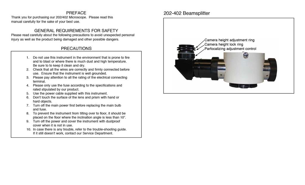
4 [A1] Straight Binocular Head [A3] inner hexagonal tightening bolt [B2] screw flange [B3] CCD adapter [B5] screw flange [B6] CCD connector [B9] dust-proof cover [B10] dust-proof cover [A2] Inclined Binocular Head 10.2 Objectives, F175mm/F250mm/F300mm/F350mm/F400mm Unscrew the objective [A4] under the microscope and fix the special objec- [A4]. The magnification is as 2.5/1.43/1.25/0.83/0.71/0.63 times as before. The size of visual field is as 0.4/0.7/0.8/1.2/1.4/1.6 times as before. (Fig. 5) x ocular Pull out the 12.5x ocular from the geminate ocular drawtubes and insert the 10x ocular. The magnification is as 0.8 times before. The size of visual field is as times as before Beam splitter, CCD adapter (1) Unscrew the inner hexagonal tightening bolt [A3] by the 2mm inner hexagram screw drive. (2) Fix the beam splitter [B1] in the microscope. (3) Select one beam split-port in the left or right side of the beam splitter as the position of the CCD adapter [B3]. Unscrew the dust-proof cover [B10] on the beam split-port and keep it well. (4) Take out the CCD adapter [B3] and screw off the dust-proof cover [B7] [B9]. Fix the CCD adapter [B3] into the 13 tive [A4] objective [B1] beam splitter [B4] focus adjusting ring [B7] dust-proof cover [B8] CCD
5 7 Responsibility We may provide the circuit diagram, electric component list and other details of the equipment at the request of customers to meet their need for repairing. If any information, service or consultation is needed, please contact us directly or with our authorized agents. 8 Transportation, Storage and Rejection During the transportation, take care to protect it from wetness, upside down and violent vibration. The relative humidity should be 10% to 90%, environmental temperature -10ºC to +40ºC and atmospheric pressure 500hPa to 1060hPa. This equipment should be stored in well-ventilated room without corrosive gas where the relative humidity should be 10% to 90% and environmental temperature -10ºC to +40ºC. If the assembled equipment needs to be moved or transported a short distance, please lock all the movable parts (refer to 5.4). The inclination angle should be less than 10º. If long distance transportation is required, please repack in original packages. 9 Spare parts and tools of the instrument 1. Medical halogen bulb with cool reflection (15v 150w) 1 2. T type AC250 2A; T type AC125 4A fuse tube 4/each 3. 6mm inner hexagonal wrench mm inner hexagonal wrench 1 5. P54M bulb socket 2 10 Assembly of the optional accessories (additional order) 10.1 Straight Binocular Head Unscrew the inner hexagonal tightening bolt [A3] by the 2mm inner hexagonal screw drive. Take down the 45º for Inclined Binocular head drawtubes [A2] and fix the erect geminate ocular drawtubes [A1]. Then screw down the inner hexagonal tightening bolt [A3] by the 2mm inner hexagram screw drive. (Fig. 5) 1. FEATURES AND SPECIFICATIONS 1.1 Features The 202/402 Operating Microscope is a portable microscope. Its small and portable machine body makes it highly agile. The microscope is a single binocular one, with three magnification steps, offering sharp image and large field of vision. A cold light source is used in the illumination system, which is harmless to the tissue of the eye. With quality halogen bulbs, PHILIPS and OSRAM, being used, the illumination is bright and even. An intensifying red-reflex module is added. A spring balance system is designed for the arm so that the microscope can move upwards and downwards stopping at any desired position. The adjusting functions of the equipment include magnification, focusing and inclination, while focusing can also be controlled by the foot switch. The environment requirements for using this equipment is temperature +10ºC to +40ºC, relative humidity 30% to 75%, atmospheric pressure 50hPa to 1060hPa. 1.2 Specifications (1) Parameter of microscope Focus length of objective f=250mm Eyepieces 12.5 x /16B magnification & visual fields Objective focus 250 Total Magnification 5X 8X 13X Visual field (mm) Illumination field (mm) (2) Working distance 240mm (3) Parameter of Binocular tube Inclined binocular tubes 45º Diopter adjustment range ±6D Pupil distance range 50mm 70mm Height of eyecups 18mm (4) Parameter of Illumination 6º+0º Coaxial illumination Maximum intensity 3000Lx or up (5) Parameter of Position adjustment Maximum stretching radius of arm 1250mm Vertical movement range (from floor to front surface of big objective) 700mm 1100mm 1
6 (6) Parameter of Electric Input voltage Input power Fuse Bulb Electrical safety AC220V±10%/50Hz ±1% or AC110V ± 10%/50hZ ± 1% 120VA T type AC250V 2A T type AC125V 4A (For example, 51S-013H, 51S-025L) 15V/150W (Medical halogen lamp bulb with cold reflection) Conform to standard IEC601-1 Type 1, Class B Trouble Illumination doesn t light TABLE 1 TROUBLE SHOOTING GUIDE Possible Cause The cable isn t connected correctly with the power socket. The position of the light adjusting knob is wrong after switching on power switches. The bulb plug doesn t connect correctly with its socket. Remedy Connect the power cable correctly. Adjust the lightadjusting knob. Take out bulb, scrape oxide. Then reinstall, screw the locking bolt firmly. The foot switch does not work. The light spot is too dark or not even The bulb has burnt (The mains exceed voltage rating). The fuse has blown The plug of foot switch is not well connected with the socket under the power controlling box. The two connectors on the second arm are not well connected. The bulb socket is not plugged correctly. The fiber optics are not inserted to the end, Replace new bulb (stabilize the voltage rating). Change the fuse. Connect again. Plug it in correctly. Insert it to the end. 6.4 Ordering consumable parts Name Specification Suggested Type YZ20P5 Operation Medical halogen bulb with cool reflection AC15V/150W HLX64634 EFR Microscope Fuse T type AC250 2A T type AC125 4A 51S-025L, 51S-013H (HOLLYLAND CO., LTD) 2
7 can be cleaned off with mirror-cleaning paper or a drop of liquid solvent (1:1 mixture of Ethyl Alcohol and water), then blow it carefully. Be careful to prevent the solvent from infitrating the edges of the lens. (4) The outer surface of the equipment may be cleaned with a wet cloth. The remaining stains can be cleaned off with the mixture of 50% C2H5OH and 50% H2O (distilled). Please do not use a corrosive cleaning agent. (5) Eyecups should be cleaned with water. Place them on the eyepieces after drying. (6) All sterilization caps should be autoclave sterilized. Suggested conditions are as follows: 120ºC, time: 20 minutes; or temperature: 134ºC, time: 5 minutes. (7) The accessories not in use should be put in a closed box with desiccant. THE NAME AND USE OF COMPONENTS 6.3 Trouble-shooting guide In case there is any trouble, please refer to the table on the next page. If the problem still exists, please contact our Service Department at (800)
8 1. Caster Move and support the equipment. 2. Foot control switch Used to control the focusing functions of microscope. 3. Floor stand Used to support and fix stand pillar. 4. Stand pillar 5. Fuse Two (1.25A/2.5A) are used to power supply. 6. Light-adjusting knob Used for continuous adjustment of illumination intensity. 7. Power supply switch Used to switch on or switch off power supply. 8. Spare bulb module In case the working bulb burns out during an operation, the spare lamp module may be inserted so as to ensure the operation to be continued smoothly. 9. Bulb module 10. Balance adjusting knob pin plug/socket (manual focus without it) 12. Fixing nut This nut lets microscope suspend on the small horizontal arm. Though there is protective melt [24], you must check whether this nut is tightened or not. 13. Star fixation knob (with sterilized cap) Fix the revolving angle of the suspended spindle of microscope. 14. Star fixation knob (with sterilized cap) Lock the microscope and make it not revolve at up and down plane. 15. Diopter adjusting ring Adjust ocular diopter by rotating this ring. The range of adjustment is ±6D. 16. Eyecups Adjust exit-pupil distance. Its height is 18mm and it may be taken off o rolled down. 17. Manipulating handle (with sterilized cap) For rough focusing, move the microscope up and down or right or left. 18. Magnification knob (with sterilized cap) Three magnification steps are provided. With different objectives the magnification factor of each step differs. Rotate the knob to change the magnification. 19. Dustproof cover of big objective It can be disinfected after being screwed off. 20. Fixing block circle Fix the manipulating handle so that it will not loosen. 21. Button To adjust the angle of the handle, you should press the button and rotate the manipulating handle [17]. 22. Focusing knob (Electric focus without this knob.) Rotate this knob to adjust the fine focus. 23. Star locking handwheel (sterile cover) Loosen this handwheel and the lens can be dragged in plane X,Y, Z. 24. Secure pin Avoid the microscope dropping when the fixing nut loosens while unloading it or suspending it. 25. Fiber optic Leads the light beam from bulbs to the operating position. 26. Star fixation knob (with sterilized cap) Lock the second arm by tightening it firmly so as to prevent the microscope from turning. 27. Star fixation knob Lock the first arm by tightening it firmly as to prevent the fuse, operation. Only use 15V, 150W halogen lamp bulbs (2) After the operation, replace the burnt bulb immediately for next operation. While replacing, pull out ceramic socket and take the bulb out of two clamping springs. Then replace a new bulb in a reverse way (Fig. 4). CAUTION: Watch out for hot bulbs. (3) Insert the bulb module to the same direction it was removed. CAUTION: Use the proper bulb for the equipment. Clay socket Compaction reed Replacing the fuse Remove the fuse holder under the power controlling box. Replace it with a new then fasten the cover. CAUTION: Only use fuses of the same type, specification and rated value. To be safe, please disconnect power from the mains outlet before removing the lower cover and replace the fuse. 6.2 Cleaning and sterilization (1) All equipment has been fully checked before delivery, ensuring its proper performance. However, proper maintenance is necessary. It should not be disassembled by unskilled or unqualified technicians. Otherwise, the equipment may be damaged and the performance may be affected. It is advised by the manufacturer that the equipment takes regular maintenance at three month intervals or according to the specific condition. (2) To avoid damage to the equipment, do not place the equipment in a dusty, moist or corrosive environment. (3) Do not assemble lenses yourself. If there is dust stains on the lens, blow them with a blowball or brush them with a dust pen. Greasy or water stains 4 9
9 (7) Eyecup [16] adjustment. The eyecup [16] can reduce the observing disturbance coming from the foreign light. The height is limited to 18mm. If a doctor wearing glasses makes the operation, the eyecup will need to be rolled down, that is turn the rubber over the ocular tube. (8) Diopter adjustment. The adjustment range of the diopter adjusting ring [15] of the ocular is ±6D, with 1D for each division. Rotate the diopter adjusting ring, match the value on the scale of the diopter adjusting ring with the diopter of the surgeon. If the surgeon wears glasses, align 0 position on the diopter adjusting ring to the white line mark on the ocular tube because glasses have corrected the surgeon s vision. (9) Pupil distance adjustment. While adjusting the pupillary distance, you can observe while rotating, until both eyes see properly, visual fields coincide and stereoscopic effect obtained. If the pupillary distance of the surgeon is known, adjust directly to this value indicated on the surface of the PD adjusting rod. * The above steps should be done before surgeon s personal sterilization. (10) Move the microscope upwards. Put the sterilization caps at the following places: Star fixation knob [13], [14], [23], [26], [33] Manipulating handle [17] Magnification knob [18] Focusing knob [22] *Disposable sterile cover may be used to cover the microscope at the surgeon s choice. After that, move the microscope to position the light spot on the center of the surgical site. microscope from turning pin plug/socket (manual focus without it) Connect the foot switch. 29. Star fixation knob Tighten it in order to lock the light source box to make it not revolve when moving or storing. 30. Inner hexagonal tightening bolt Lock the stand pillar and the light source box /220V selecting switch 32. Power plug Input power supply 33. Star fixation knob (with sterilized cap) Tighten it in order to lock the little arm and make the microscope not move vertically. ASSEMBLY This equipment may be installed either by the user with reference to the manual or by the servicemen sent by the manufacturer or authorized representatives when facing real difficulties. This equipment is packed in two packages. Please open the packages in the direction indicated by the mark on the packages. Take out all the parts and assemble them according to the following procedures: 5.3 Movement and storage after use (1) Put off all of the sterilized cap an knob and sterilize them for the next use. (2) Draw the microscope back to the nearest position to the stand. Fasten every star knob firmly so as to fix the arm and the microscope. (3) Disconnect power wire and foot switch plug, store in a suitable place. (4) Loosen the brake of the caster [1] before moving. (5) Grasp the power control box firmly with two hands in order to move the equipment slowly and carefully, meanwhile avoid bumping and leaning. (6) Replace burnt bulb if any for the next use. Refer to method MAINTENANCE 6.1 Replacing the consumable parts. CAUTION: Replaced parts are treated as ordinary industrial rubbish Replacing the bulbs (1) The lamp house is equipped with a spare bulb module [8]. In case the bulb burns out during operation, you only need to turn off power and pull out the 8 bulb module [9] (Fig. 7) then insert the spare bulb module [8] to the same direction as being pulled out. After that, switch power on and continue 5
10 3.1 Assembly of stand pillar (1) Please take out the floor stand [3] from the package, lay it on the ground. (2) Take out the stand pillar [4], turn out the inner hexagonal bolt and gasket of its end, insert it into the hole of the floor stand [3], and then turn the stand pillar [4] to make the column groove lock into pin on the base, re-assemble in order with 10mm hexagonal wrench (Fig. 2). 3.2 Assembly of light source box Take out the light source box while not loosening the tightening bolt of the star knob [33] in order to avoid the second arm rebounding and harm people, set the bottom of the light source box into the stand pillar [4] and insert the inner hexagonal tightening bolt [30] into the groove of the end of stand pillar [4] and fasten it firmly with 6mm hexagonal wrench (Fig. 2). 3.3 Assembly of microscope (1) First check the tightening bolt of star knob [13], make sure that the end of the bolt does not protrude out of the hole surface. (2) Remove the fixing nut [12]. Pull out the secure pin [24] with one hand, hold the connecting part of microscope with another hand. Insert the shaft into the hole of the arm from the bottom to top. Then release the secure pin [24], it will spring back to the groove on the shaft. Finally, fasten the fixing nut [12] (Fig. 2). 3.4 Assembly of manipulating handle Insert the manipulating handle [17] into the holes on the two sides of the microscope holder respectively. The proper handle position should be down to an angle of 40º (as shown in Fig. 1). 3.5 Assembly of fiber optics (1) Remove the fiber optics protective cover. (2) Insert one end of the fiber optics [25] into the side of the light source box and insert another end into the hole behind the microscope (Fig. 2). 4. PREPARATION FOR USE (1) Check whether the main voltage, frequency complies with what is required by the equipment. If not, do not start it. CAUTION: Set the input voltage at 110V. When it is 220V, please switch the selecting switch [31] to the 220 block and change the fuse [5] as type AC1.25 or 2.5A fuse tube we supplied. (2) Check the grounding of power supply. Make sure the equipment has a good ground-wire connection. (3) The equipment comes with a three-core power cable. Please select matched power socket. 6CAUTION: Please use the power cable provided by the manufacturer or the power cable according with IEC227 standard to ensure that the equipment is well grounded. (4) When the power switch [7] on the power controlling box is pressed ON position, power is on. When pressed at OFF position, power is off. The switch should always be OFF before the power wire is connected with power socket. (5) Insert the plug of the power wire of the equipment into the mains outlet (It must be well grounded). (6) Switch on the power. Check whether the illumination system works properly. (7) After checking, please turn off power switch on power controlling box and disconnect the power plug and cover the equipment with dust cover. 5. USE OF INSTRUMENT 5.1 Installation and adjustment before the use (1) Sterilize the manipulating handles and sterilizable caps in advance. (2) Move the second arm to a horizontal position. Adjust the height, ensure that the objective is about 250mm from the surgical site. (3) Switch on power supply, check the bulbs. If any bulb burns out, replace it immediately. CAUTION: Burnt bulbs must be replaced before and operation to ensure that the operation may be performed without interruption. BULBS MAY BE HOT! 5.2 Adjustment during use (1) First move the equipment to a proper position and apply the brake to prevent the equipment from moving easily. Connect the power plug with power socket [32] on the microscope. (2) Place the foot switch [2] to a suitable position. Connect the 5-pin plug of the foot switch with the socket under the power controlling box. (3) Insert the plug of power cable under the power controlling box into the mains outlet. Then switch on the power switch [7]. (4) Move the fine focusing drag to the starting position, where the fine focusing indicator points to the central point of the drive, by using the foot switch [2] or the focusing knob. (5) Illumination intensity adjustment. Rotate the light adjusting knob [6] on the power controlling box clockwise to increase intensity, counterclockwise to reduce the intensity. Adjust it until intensity is satisfactory. (6) Rough focusing. Loosen the star fixation knob [33], hold the handle [17] to move the microscope upwards or downwards to position the light spot on the surgical site and adjust the focus until the image is clear with 8x magnification. Manipulating method refers to 5.1(2). Rotate the focusing knob while manual focusing. 7
AM-3000 Surgical Microscope User s Manual
 AM-3000 Surgical Microscope User s Manual Alltion (Wuzhou) Co., Ltd. Alltion (Guangxi) Instrument Co., Ltd. Alltion Building, No. 10, 3rd Road, Industrial Boulevard, Wuzhou Industrial Park, Wuzhou, Guangxi,
Preface. Scope of Application. General Requirements for Safety THE SAFETY MARKS USED IN THIS INSTRUMENT
 Preface Thank you for purchasing our SL-700 slit lamp. Please read this manual carefully before using this instrument in order to operate it properly and safely. Scope of Application The slit lamp is mainly
USER MANUAL. SLIT LAMP MICROSCOPE Model: GR-7. Version: 1.0. Gilras LLC
 USER MANUAL SLIT LAMP MICROSCOPE Model: GR-7 Version: 1.0 Gilras LLC Thank you for purchasing our slit lamp microscope. The following is the description and specification of our product. General description
USER MANUAL SLIT LAMP MICROSCOPE
 USER MANUAL SLIT LAMP MICROSCOPE 1 Thank you for purchasing our product. The following is the description and specifications of the instrument. General description This user manual elaborates on the relevant
Prima OPH User Manual
 R Prima OPH User Manual Ophthalmic Microscopy To ensure proper use of this instrument as well as to avoid injury while operating instrument, understanding this manual completely before use is highly recommended.
PRIMA DNT User Manual
 R PRIMA DNT User Manual Operating Surgical Microscopy To ensure proper use of this instrument as well as to avoid injury while operating instrument, understanding this manual completely before use is highly
USER S MANUAL SILT LAMP SL 880
 USER S MANUAL SILT LAMP SL 880 Notification Dear Users, Thank you for your purchase of SL 880 Slit Lamp. Please take time to read our user s manual carefully before use. This guarantees you to make full
SCAN OPTICS SO-161-R MICROSCOPE USER MANUAL
 SCAN OPTICS SO-161-R MICROSCOPE USER MANUAL SO-161-R Ophthalmic Microscope User Manual Page 2 of 18 CONTENTS CONTENTS 2 LIST OF FIGURES 2 INTRODUCTION 3 INTRODUCTION 3 PARTS LIST 5 ASSEMBLY INSTRUCTIONS
Table of Contents. Classifications.. 5. Installation.,12. Focusing..14. Operating Instructions..15. Charts Description Maintenance...
 -1- Table of Contents Introduction 3 Package Contents 4 Classifications.. 5 Designated Symbols 6 Safety Instructions 7 Instrument Components 9 Installation.,12 Focusing..14 Operating Instructions..15 Charts
Stereo Microscopes Instruction Manual
 Stereo Microscopes Instruction Manual Thank you for purchasing an Omano microscope. We hope you enjoy it. It has been checked for quality before shipping, but please take time to ensure that it has not
MANUAL EXC-120 MICROSCOPE SERIES. 73 Mall Drive, Commack, NY (P) (F)
 (F)") MANUAL EXC-0 MICROSCOPE SERIES 73 Mall Drive, Commack, NY 75 63-864-000 (P) 63-543-8900 (F) www.accu-scope.com info@accu-scope.com CONTENTS SAFETY NOTES... CARE AND MAINTENANCE... INTRODUCTION... 3 UNPACKING
MANUAL EXC-0 MICROSCOPE SERIES 73 Mall Drive, Commack, NY 75 63-864-000 (P) 63-543-8900 (F) www.accu-scope.com info@accu-scope.com CONTENTS SAFETY NOTES... CARE AND MAINTENANCE... INTRODUCTION... 3 UNPACKING
AMCON AUTOMATIC CHART PROJECTOR USER S MANUAL EQ-6002
 AMCON AUTOMATIC CHART PROJECTOR USER S MANUAL EQ-6002 1-800-255-6161 Fax 1-800-397-0013 www.amconlabs.com Disclaimer...2 1. Introduction...3 2. Safety Instructions......3 3. Charts and Specifications......4
SZ2-ILA INSTRUCTIONS TRANSMITTED ILLUMINATION ATTACHMENT SZ-ADD SZ-POL-2 SZH-CLJ. Optional Modules
 Optional Modules SZ-ADD SZ-POL-2 SZH-CLJ INSTRUCTIONS TRANSMITTED ILLUMINATION ATTACHMENT This instruction manual is for the Olympus Transmitted Illumination Attachment. To ensure the safety, obtain optimum
USER MANUAL LUX-LD30W LED MOVING HEAD
 USER MANUAL LUX-LD30W LED MOVING HEAD LUX-LD30W LED MOVING HEAD For indoor use only Caution! Please read this manual carefully before operating! Damage caused by misuse is not covered by the warranty!
XPERT SL 45 Slit Lamp. Instruction Manual
 R XPERT SL 45 Slit Lamp Instruction Manual INDEX INTRODUCTION 1 1.0 Safety Instructions 2 2.0 Packing List 3 3.0 Parts Description 4 4.0 Installation 5-6 5.0 Operating Procedure 7-8 6.0 Lamp and Fuse Replacement
LED Twister II. User manual UK Version 1.0
 LED Twister II User manual 152.624UK Version 1.0 LED DUOPLEX: For indoor use only CAUTION! Please read this manual carefully before operating! Pay special attention to Sections 3 & 5 of this document.
INTRODUCTION...5 PARTS LIST...6 PACKAGING...9
 SO-111W Microscope INTRODUCTION...5 PARTS LIST...6 PACKAGING...9 ASSEMBLY INSTRUCTIONS... 10 Fixing to a table 10 Assembling the arm and head 10 Connecting to a power source 13 Changing the light intensity
12 Volt dc supply Connecting the power supply to a 12 Volt dc supply (battery)... 12
... 12") SO-161 Ophthalmic icroscope User anual Page 1 of 25 Page 1 of 25 CONTENTS PARTS LIST... 4 UNPACKING AND INSTALLATION... 5 12 Volt dc supply... 11 Connecting the power supply to a 12 Volt dc supply (battery)...
SO-161 Ophthalmic icroscope User anual Page 1 of 25 Page 1 of 25 CONTENTS PARTS LIST... 4 UNPACKING AND INSTALLATION... 5 12 Volt dc supply... 11 Connecting the power supply to a 12 Volt dc supply (battery)...
SCAN OPTICS SO-5800 MICROSCOPE ASSEMBLY MANUAL
 SCAN OPTICS SO-5800 MICROSCOPE ASSEMBLY MANUAL SO-5800 Ophthalmic Microscope Assembly Manual Page 2 of 25 CONTENTS INTRODUCTION... 3 PACKING LIST... 5 MECHANICAL ASSEMBLY... 6 Floor stand base and pillar...
INTRODUCTION...5 PARTS LIST...6 PACKAGING...9 ASSEMBLY INSTRUCTIONS... 10
 SO-111WF Microscope INTRODUCTION...5 PARTS LIST...6 PACKAGING...9 ASSEMBLY INSTRUCTIONS... 10 Fixing to a table 10 Assembling the arm and head 10 Connecting to a power source 13 Changing the light intensity
Snapshot LX5 USER MANUAL. OK on Dimmer Outdoor OK Sound Activated DMX512 Master/Slave 115V/230V Switch Replaceable Fuse User Serviceable Duty Cycle
 LX5 Snapshot OK on Dimmer Outdoor OK Sound Activated DMX512 Master/Slave 115V/230V Switch Replaceable Fuse User Serviceable Duty Cycle USER MANUAL Chauvet, 5200 NW 108th Avenue, Sunrise, FL 33351 U.S.A.
XCEL 250 XCEL 400/700. Xcel Slit Lamp USER'S GUIDE Rev. F Page1
 XCEL 250 XCEL 400/700 Xcel Slit Lamp USER'S GUIDE 12560-101 Rev. F Page1 Page 2 12560-101 Rev. F Table of Contents INTRODUCTION...4 XCEL 250 COMPONENTS...5 XCEL 400 / 700 COMPONENTS...6 INSTALLATION...7
Compact LED profile with zoom
 Compact LED profile with zoom 2 11 TABLE OF CONTENTS SAFETY / GENERAL INSTRUCTIONS INTRODUCTION Features Specifications OVERVIEW Rear view Top view MOUNTING CONTROL MENU OVERVIEW Control Panel Function
Hand Pallet Truck NC. Operation Manual
 Hand Pallet Truck -------NC Operation Manual Operation Manual 1 Application Range This product is suitable for using in rated load of up to 5500lbs. This PL5500HD is the perfect jack for handling palletized
AP250 Automated Projector
 AP0 Automated Projector User s Guide 13800-1-Rev. A 13 Contents Introduction The AP0 is used for measuring visual acuity. 2 Package Contents Your new Leica AP0 and accessories 2 Safety Precautions Safety
User s Manual Dental Microscope LED
 SEILER IQ User s Manual Dental Microscope LED Table of Contents Installation and Assembly 1 LED Illumination System Instructions 6 Description 9 Set Up 10 Maintenance 11 Specifications 12 Environmental
Snapshot LX10 USER MANUAL. OK on Dimmer Outdoor OK Sound Activated DMX512 Master/Slave 115V/230V Switch Replaceable Fuse User Serviceable Duty Cycle
 LX10 Snapshot OK on Dimmer Outdoor OK Sound Activated DMX512 Master/Slave 115V/230V Switch Replaceable Fuse User Serviceable Duty Cycle USER MANUAL Chauvet, 3000 N 29 th Ct, Hollywood, FL 33020 U.S.A.
C.fm Page 1 Thursday, February 21, :28 AM Raptor user manual
 Raptor user manual 1 mounting bracket 2 swivel lock 3 clamp hole 4 lamp access screws 5 air vents 6 AC input & main fuse 7 cooling fan Thank you for selecting the Martin Raptor. This Martin lighting fixture
P/N Wheeler. user manual
 P/N 35000068 Wheeler user manual 1998, 1999 Martin Professional A/S, Denmark. All rights reserved. No part of this manual may be reproduced, in any form or by any means, without permission in writing from
ECO Spot 2500 User Manual
 ECO Spot 2500 User Manual Thank you for choosing an ECO Spot 2500 Profile Spot. The projector part is based on a modified ETC Source Four and most of the available standard Source Four equipment, such
ECO Spot 2500 User Manual
 ECO Spot 2500 User Manual Thank you for choosing an ECO Spot 2500 Profile Spot. The projector part is based on a modified ETC Source Four and most of the available standard Source Four equipment, such
FL15 FL50 FL100 USER MANUAL USER MANUAL FL15 PRODUCT OVERVIEW HARDWARE AND SET-UP. page 1
 PRODUCT OVERVIEW The FL15, FL50 and FL100 are LED luminaries designed for use with fiber optics for illumination purposes. This FiberLamp line can be used with both end-emitting and side-emitting fiber
Light Source User Guide
 Light Source User Guide Slimline Light Source Range Models covered by this manual: UFO 35 SL-G(D) UFO 35 SL-P(D) UFO 42 SL-G(D) UFO 42 SL-P(D) UFO 50 SL-G(D) UFO 50 SL-P(D) UFO 75 SL-G(D) UFO 75 SL-P(D)
CENTERING DEVICE. Model CE-1 OPERATOR S MANUAL
 CENTERING DEVICE Model CE-1 OPERATOR S MANUAL NIDEK CO., LTD. : 34-14, Maehama, Hiroishi-cho, Gamagori, Aichi 443-0038, Japan (Manufacturer) Telephone: (0533) 67-6611 Facsimile: (0533) 67-6610 NIDEK CO.,
STAND MODEL FOR MACH M2
 Mounting instructions Directions for use STAND MODEL FOR MACH M2 Stand lamps: Mach M2... Mach M2 F... Order No. 170 120 1300 Order No. 170 230 1300 GmbH u. Co. KG, Flossmannstrasse 28, D-85560 Ebersberg
User Manual. Snapshot. Use on Dimmer. Outdoor Use. Sound Activated DMX 512. Master/Slave. 115/230V Power Switch. Replaceable Fuse.
 Snapshot Use on Dimmer Outdoor Use Sound Activated DMX 512 Master/Slave 115/230V Power Switch Replaceable Fuse User Serviceable Duty Cycle User Manual 3000 N 29 th Ct, Hollywood, FL 33020 U.S.A. (800)
HALOGEN FLOODLIGHTS Models CHL1260C & 1260T Part Nos: &
 HALOGEN FLOODLIGHTS Models CHL1260C & 1260T Part Nos: 5460600 & 5460595 OPERATING & MAINTENANCE INSTRUCTIONS GC0610 INTRODUCTION Thank you for purchasing this CLARKE Halogen Floodlight. Before attempting
Mania DC3 user manual
 Mania DC3 user manual Measurements are expressed in millimeters. Ø13 310 160 215 340 290 2004 Martin Professional A/S, Denmark. All rights reserved. No part of this manual may be reproduced, in any form
Demco. Model E Bedienungsanleitung Instruction manual Mode d emploi Istruzioni d uso Instrucciones para el servicio Инструкция по эксплуатации
 Demco Model E96-230 Bedienungsanleitung Instruction manual Mode d emploi Istruzioni d uso Instrucciones para el servicio Инструкция по эксплуатации Manufactured by: CMP Industries LLC 413 N. Pearl St.
Keeler Spectra Plus. Instructions. Next
 Keeler Spectra Plus Instructions Next Introduction Thank you for purchasing the Keeler Spectra Plus Indirect Ophthalmoscope. We have taken the greatest care in the design, development and manufacture of
SO-111 Ophthalmic Microscope User Manual Page 1 of 30 CONTENTS
 SO-111 Ophthalmic icroscope User anual Page 1 of 30 CONTENTS PARTS LIST... 4 UNPACKING AND INSTALLATION... 5 12 Volt dc supply... 11 Connecting the power supply to a 12 Volt dc supply (battery)... 12 DISANTLING
User Guide for Logo Projector
 User Guide for Logo Projector Professional Entertainment Technology . TABLE OF CONTENTS 1. Introduction 2. Safety Instruction 3. Description 4. Operation and Technical Specification 5. Lamp Installation
A B 0 0 C D E 6 7 G F F H 8 9 K M O O L N I J 1
 1 2 1 5 4 3 2 2 1 6 3 8 7 1 9 4 C A B 5 0 0 D E 6 G 7 F F H 8 K 9 M O O I J L N 1 GENERAL OPERATIONAL PRECAUTIONS 1. Keep work area clean. Cluttered areas and benches invite accidents. 2. Avoid dangerous
1 MECHANICAL FUEL METER
 1 MECHANICAL FUEL METER USER S MANUAL WARNING: Read carefully and understand all INSTRUCTIONS before operating. Failure to follow the safety rules and other basic safety precautions may result in serious
IR BGA Rework Station T862++ User Manual
 IR BGA Rework Station T862++ TAIAN PUHUI ELECTRIC TECHNOLOGY CO.,LTD www.tech168.cn CONTENT 1. Features...2 2. Technical Parameters..3 3. List of content...... 3 4. Description of the main parts.....4
Changing light bulbs. Introduction WARNING
 Changing light bulbs Introduction In this section you ll find information about: Indicator light Information on light bulb replacement Changing headlight bulbs Changing the fog light bulbs in the front
D.fm Page 1 Wednesday, March 5, :21 PM Raptor user manual
 Raptor user manual 1 mounting bracket 2 swivel lock 3 clamp hole 4 lamp access screws 5 air vents 2001-2002 Martin Professional A/S, Denmark. All rights reserved. No part of this manual may be reproduced,
ACROBAT SWING STAND MODEL
 Mounting instructions Directions for use ACROBAT SWING STAND MODEL Dr. Mach GmbH u. Co.KG, Flossmannstrasse 28, D-85560 Ebersberg Tel.: +49 (0)8092 2093 0, Fax +49 (0)8092 2093 50 Internet: www.dr-mach.com,
KENSUN HID AUTOMOTIVE HEAD LAMP CONVERSION KIT INSTALLATION MANUAL
 1 KENSUN HID AUTOMOTIVE HEAD LAMP CONVERSION KIT INSTALLATION MANUAL 2 CONTENTS A. Before Installing B. Installing the Bulbs C. Installing the Ballasts D. For Bi Xenon Only: Installing the Relay Harness
MOVING HEAD. User manual CAUTION!
 TM MOVING HEAD OBY-3 User manual CAUTION! contents Features Description of the appearance Inspection. Safety instructions Lamp Installation Rigging Connection with the mains Linking Instruction for gobo
IRDA-WELDER User Manual. Model: T862++
 IRDA-WELDER Model: T862++ CATALOGUE 1. Features..2 2. Technical Parameter and Components 3 3. T-862++ Illustrated Explanation 4 (1)The Whole Machine 4 (2)Front panel and Rear panel...5 (3)IR Lamp Body(Focus
Snapshot. Use on Dimmer Outdoor Use Sound-Activated DMX Master/Slave 120 V/230 V Switchable Replaceable Fuse User-Serviceable.
 Snapshot Use on Dimmer Outdoor Use Sound-Activated DMX Master/Slave 120 V/230 V Switchable Replaceable Fuse User-Serviceable User Manual TABLE OF CONTENTS 1. BEFORE YOU BEGIN... 3 WHAT IS INCLUDED... 3
Mania EF1 user manual
 Mania EF1 user manual Measurements are expressed in millimeters. 290 142 312 Ø13 250 2003 Martin Professional A/S, Denmark. All rights reserved. No part of this manual may be reproduced, in any form or
USER MANUAL PAR56 LED PAR CANS
 USER MANUAL PAR56 LED PAR CANS 153.766 / 153.769 Slimline PAR64 LED Par can For indoor use only Caution! Please read this manual carefully before operating! Damage caused by misuse is not covered by the
Installation Operation Maintenance Troubleshooting Version2.1. Feb/09. Led II
 Installation Operation Maintenance Troubleshooting Version2.1. Feb/09 Led II INDEX Safety Regulation 3 Components 4 User s Guide 9 Product Installation 10 Operation Method 11 Maintenance and Repair 13
ACROBAT SWING STAND MODEL
 Mounting instructions Directions for use ACROBAT SWING STAND MODEL Stand lamps: Mach 120... Mach 120F... Mach 130... Mach 130F... Mach LED 120... Mach LED 120F... Mach LED 130... Mach LED 130F... Order
LED NEUTRON 4 x QUAD COLOUR LED LIGHT EFFECT
 TECHNICAL SPECIFICATION: Voltage : 230Vac, 50Hz Power Consumption: 60W LED Type : 4 x 4-in-1 Quad LED Fuse: F3A RGBW LED Power: 4 x 10W Quad LED LED Lifespan: 10,000hrs DMX Channels: 6 or 21 Dimensions
Ego 01 Ego 02 Ego 03 Logo Projector user manual
 Ego 01 Ego 02 Ego 03 Logo Projector user manual Measurements are expressed in millimeters. 324 305 150 248 2002 Martin Professional A/S, Denmark. All rights reserved. No part of this manual may be reproduced,
FL Halogen light generator for use with fibre optic lighting. Mounting and installation instruction. Item no.: FL 20-2 Ø9 230V
 FL 20-2 Halogen light generator for use with fibre optic lighting User Manual Mounting and installation instruction. Item no.: 0120 0001 FL 20-2 Ø9 230V +99082106 rev. 25.09.2106 1. Introduction This manual
SO-801 HAND-HELD SLIT LAMP SO-801
 SO-801 HAND-HELD SLIT LAMP SO-801 SO-801 HAND-HELD SLIT LAMP Scan Optics University of Adelaide Research Precinct 32 Stirling Street, Thebarton SA 5031, Adelaide, Australia Tel: 61 (8) 8234 9120 Fax: 61
Microscope light manual
 Microscope light manual LS-12 and LS-14 LS-12 LS-14 1/9 Content Overview... 3 Mounting... 4 Light adjustment... 5 Mirror... 6 Filters... 6 Replacing microscope light... 7 Technical data... 8 Troubleshooting...
NIDEK OPHTHALMIC YAG LASER SYSTEM
 IDEK OPHTHALMIC AG LASER SSTEM Model C-1600 SERVICE MAUAL XC14*RDA001E/E Total pages: 105 2005. 3.3 HEAD OFFICE : 34-14, Maehama, Hiroishi-cho, Gamagori, Aichi 443-0038, Japan Telephone: (0533) 67-6611
LED Pinspot 2. Snapshot. User Manual
 LED Pinspot 2 Snapshot Use on Dimmer Outdoor Use Sound Activated DMX Master/Slave Auto-ranging Power Supply Replaceable Fuse User Serviceable Duty Cycle User Manual 3000 N 29 th Ct, Hollywood, FL 33020
USER S MANUAL TUBE SEALER. Model SE250. No. CAT.SE25010Ce
 USER S MANUAL TUBE SEALER Model SE250 No. CAT.SE25010Ce Centron Technologies Corporation 319-25 Sadang-4-dong, Dongjak-ku Seoul, Korea 156-823 Tel. +82-2.522.7807 Fax +82-2.522.7806 Important Note 1. Safety
Tactical Laser Illuminator
 M6 Operator s Manual Operator s Manual Tactical Laser Illuminator MADE IN THE USA Table of Contents Section Page Warnings and Cautions... 1 Safety Summary... 4 M6 TLI (Tactical Laser Illuminator) Parts
Snapshot Ok on Dimmer Outdoor OK Sound Activated DMX512 Master/Slave 115V/230V Switch Replaceable Fuse User Serviceable Duty Cycle
 SX Scope Snapshot Ok on Dimmer Outdoor OK Sound Activated DMX512 Master/Slave 115V/230V Switch Replaceable Fuse User Serviceable Duty Cycle USER MANUAL Chauvet, 3000 N 29 th Ct, Hollywood, FL 33020 U.S.A.
HyperFlex 12G.
 HyperFlex 12G USER MANUAL www.venuelightingeffects.com Table of contents Introduction...2 safety precautions...3 UNIT OVERVIEW...4 rigging the fixtures...4 Lamp Installation/Replacement...5 gobo Selection
π H-2319 PORTABLE STRETCH WRAP DISPENSER uline.com TOOLS NEEDED 9/16" Crescent Wrench 9/16" Socket Wrench
 π H-2319 PORTABLE STRETCH WRAP DISPENSER 1-800-295-5510 uline.com TOOLS NEEDED 9/16" Crescent Wrench 9/16" Socket Wrench PAGE 1 OF 5 PARTS COUNT PIECES BEFORE ASSEMBLING CONTENTS OF PACKAGE 1 (The Main
Operating Manual for. Dispenser. Read this manual thoroughly before operating the Labmax Bottle Top Dispenser!
 Operating Manual for Dispenser Read this manual thoroughly before operating the Labmax Bottle Top Dispenser! General Safety Precautions When using the Labmax please observe the following safety precautions
LED Pinspot 2. Snapshot. User Manual
 LED Pinspot 2 Snapshot Use on Dimmer Outdoor Use Sound-Activated DMX Master/Slave Auto-ranging Power Supply Replaceable Fuse User-Serviceable User Manual 5200 NW 108th Avenue, Sunrise, FL 33351 U.S.A.
LAMPS 8L - 1 LAMPS CONTENTS
 TJ LAMPS 8L - 1 LAMPS CONTENTS BULB APPLICATION... 16 HEADLAMP ALIGNMENT... 5 LAMP BULB SERVICE... 8 LAMP DIAGNOSIS... 1 LAMP SERVICE... 11 LAMP SYSTEMS... 15 LAMP DIAGNOSIS INDEX GENERAL INFORMATION GENERAL
PLATE LOUPE PL-2 INSTRUCTION MANUAL. NEITZ INSTRUMENTS CO., LTD. International Division
 PLATE LOUPE PL-2 INSTRUCTION MANUAL NEITZ INSTRUMENTS CO., LTD. International Division 2013.06 Thank you for purchasing the NEITZ PLATE LOUPE PL-2 with titanium frame. Before use, please read this instruction
Industrial flue gas probes. Instruction manual
 Industrial flue gas probes Instruction manual 2 1 Contents 1 Contents 1 Contents... 3 2 Safety and the environment... 4 2.1. About this document... 4 2.2. Ensure safety... 4 2.3. Protecting the environment...
1. General Description
 General Description 1. General Description A: SPECIFICATION Front Rear Model Wheel arch height (Tolerance: +12 mm 24 mm ( +0.47 in 0.94 in)) mm (in) 376 (14.8) Camber (Tolerance: 0 45 Differences between
354 Mobile Lighting System
 Important Information Page 2 Installation and Operation Manual 354 Mobile Lighting System Installation Page 3 Description Page 12 Components Overview Page 13 Controls & Indicators Page 14 Operation Page
SDOMEO51MV USER MANUAL. Portable Rugged PTZ Cameras
 SDOMEO51MV USER MANUAL Portable Rugged PTZ Cameras Table of Contents ABOUT THE PRODUCT... 3 Features... 4 Functions... 5 Technical Data... 8 PREPARATION... 10 Dip Switch... 10 Initial Power On Test...
Section X STEERING DATA AND SPECIFICATIONS. 21 degrees 45 minutes -f- or 1 degree (inner wheel when outer wheel is 20 degrees)
") 76 Section X DATA AND SPECIFICATIONS MODELS MC-1 MG-2 MC-3 MY-1 Steering Type Manual Power Worm and Three Tooth Roller None None None Rack and Gear Sector, Recirculating Ball Nut Ratio Manual 20.4... Power
76 Section X DATA AND SPECIFICATIONS MODELS MC-1 MG-2 MC-3 MY-1 Steering Type Manual Power Worm and Three Tooth Roller None None None Rack and Gear Sector, Recirculating Ball Nut Ratio Manual 20.4... Power
OPERATING MANUAL POWER DRIVE SYSTEM. Cat. No RevH
 OPERATING MANUAL POWER DRIVE SYSTEM Cat. No. 400005 525-1300-00 RevH System components Symbol Definitions Qty Description Catalog Number 1 Power Drive System 300106 1 Controller 300108 1 Cutter Drive
Measurements are expressed in millimeters.
 T-Rex user manual Measurements are expressed in millimeters. 1 Lamp access 2 Focus adjustment 3 Mounting bracket 4 Swivel locks 5 Clamp hole 6 Air vent 190 285 7 AC input & main fuse 8 Microphone 490 164
MAINTENANCE OF PR MOVING HEADS
 MAINTENANCE OF PR MOVING HEADS General Maintenance 1.Structure 2. Trouble Shooting 3. Cleaning And Lubrication Structure Structure of Moving Head Head Arm Base Structure Base Main PCB Magnetic ballast
ASSEMBLY MANUAL OMS-90
 ASSEMBLY MANUAL OMS-90 INTRODUCTION This manual should be used by an authorized TOPCON dealer only to assemble the Operation Microscope OMS-90. Two or more persons must assemble this instrument because
Disc Grinder Model G 18MR G 23MR G 23MRU
 Disc Grinder Model G 18MR G 23MR G 23MRU Handling instructions G23MR NOTE: Before using this Electric Power Tool, carefully read through these HANDLING INSTRUCTIONS to ensure efficient, safe operation.
Light Source User Guide
 Light Source User Guide Compact Light Source Range Models covered by this manual: UFO 70/150 CG Glass, White Light - 240V UFO 70/150 CP Plastic, White Light - 240V UFO 70/150 CGC Glass, Colour Wheel (continuous)
Technicians & Nurses Program
 ASCRS ASOA Symposium & Congress Technicians & Nurses Program May 6-10, 2016 New Orleans Cole Eye Institute Ophthalmic Equipment Repair and Maintenance Certified By 1. Haag Streit 2. Relance Medical 3.
EASY CHARGE Waterproof portable Battery Charger
 EASY CHARGE Waterproof portable Battery Charger 1.1 AND 4.3 AMP MODELS EN NL, DE, FR, ES, IT USER S MANUAL WWW.MASTERVOLT.COM/EASYCHARGE-PORTABLE 10000009117/04 2 EN / EasyCharge 1.1 and 4.3 Amp - User
Fig. 2: Unclasp the wiring attached to the back of the headlamp bulb
 REMOVAL & INSTALLATION See Figures 1 through 5 Fig. 1: Examples of various types of automotive light bulbs Fig. 2: Unclasp the wiring attached to the back of the headlamp bulb This procedure only applies
COYOTE ENTERPRISES, INC. 9/10 BLAST WHEEL MAINTENANCE & ASSEMBLY MANUAL
 COYOTE ENTERPRISES, INC. 9/10 BLAST WHEEL MAINTENANCE & ASSEMBLY MANUAL Parts & Machinery for the Abrasive Blast Industry 27301 East 121st Street Coweta, Oklahoma 74429 (918) 486-8411 Fax (918) 486-8412
Operation Manual LAM 10M IR 3A LASER AIMING MODULE / TARGET POINTER. 105 Sparks Ave., Toronto, ON, M2H 2S5, Canada
 Operation Manual LAM 10M IR 3A LASER AIMING MODULE / TARGET POINTER 105 Sparks Ave., Toronto, ON, M2H 2S5, Canada LASER RADIATION AVOID EXPOSURE TO THE BEAM INFRARED LASER OUTPUT POWER
SIP Direct Drive Oil-Lube Air Compressors - Operating & Maintenance Instructions
 SIP Direct Drive Oil-Lube Air Compressors - Operating & Maintenance Instructions Please read and fully understand the instructions in this manual before operation. Keep this manual safe for future reference.
Installation, Operation, & Maintenance Manual
 Installation, Operation, & Maintenance Manual Model WelkerScope LITE The information in this manual has been carefully checked for accuracy and is intended to be used as a guide to operations. Correct
TOYOTA TRUCKS / SUVs COLD AIR INTAKE Section I Installation Preparation. 4.0L V6 (1GR-FE) Part Number(s): PTR
 Part Number(s): PTR") Section I Installation Preparation Part Number(s): PTR05-35061 Kit Contents Item # Quantity Reqd. Description 1 1 Intake Tube 2 1 Air Filter Housing 3 1 TRD Air Filter w/ #096 clamp 4 1 Adapter, Filter
Section I Installation Preparation Part Number(s): PTR05-35061 Kit Contents Item # Quantity Reqd. Description 1 1 Intake Tube 2 1 Air Filter Housing 3 1 TRD Air Filter w/ #096 clamp 4 1 Adapter, Filter
OPERATION MANUAL MODEL MODEL MODEL MODEL MODEL NON-CONDUCTIVE ARTICULATING FIBERSCOPE INSTRUMENT TECHNOLOGY, INC.
 OPERATION MANUAL MODEL 177704 MODEL 177705 MODEL 177706 MODEL 177708 MODEL 177712 NON-CONDUCTIVE ARTICULATING FIBERSCOPE INSTRUMENT TECHNOLOGY, INC. POB 381, Westfield, MA 01086 33 Airport Road, Westfield,
Alternating Current Revolution per minute Protective Earth Ground. Protected from dripping water Fuse Attention, Consult Accompanying Document
 GLOSSARY OF SYMBOLS: (Symbols and descriptions) Alternating Current Revolution per minute Protective Earth Ground Direct Current On (Power connection Off (power to the mains) disconnection from the mains)
Xenon Fiberoptic Lightsource
 Xenon Fiberoptic Lightsource Operating Instructions for ASB-XE-175W Lightsource 2659A Pan American Frw N.E Albuquerque, New Mexico 87107 USA (English) Page 1 of 12 TABLE OF CONTENTS PAGE 1. INTRODUCTION
Motion System Components Diagram. Note: #2 Mirror Cover and X-Axis Motor Cover have been removed for visibility. Maintenance.
 Professional Laser System PLS3.75, PLS4.75, PLS6.75 and PLS6.150D Keeping the laser system clean will ensure the highest quality engraving. A clean laser system is the best performing laser system. The
CH-158 Color Bank 8 USER MANUAL
 CH-158 Color Bank 8 USER MANUAL CHAUVET, 3000 N 29 th Ct, Hollywood, FL 33020 U.S.A (800) 762-1084 (954) 929-1115 FAX (954) 929-5560 www.chauvetlighting.com TABLE OF CONTENT BEFORE YOU BEGIN... 3 WHAT
3. Operating instructions: Minor 200
 1. Technical specifications 3. Operating instructions: Minor 200 Copyright 2015 by Endecotts Ltd. 13 1. Setting up Technical specifications SIEVE SHAKER MODEL: Minor 200 General Information The Minor 200
LANCER FOG LAMP KIT MZ380479EX (for RHD) INSTALLATION AND HANDLING INSTRUCTIONS
 INSTALLATION AND HANDLING INSTRUCTIONS") LANCER FOG LAMP KIT MZ380479EX (for RHD) INSTALLATION AND HANDLING INSTRUCTIONS Fog lamp Thank you for purchasing the Mitsubishi Genuine Accessory. To install and use the product correctly with proper
LANCER FOG LAMP KIT MZ380479EX (for RHD) INSTALLATION AND HANDLING INSTRUCTIONS Fog lamp Thank you for purchasing the Mitsubishi Genuine Accessory. To install and use the product correctly with proper
LyteLaunch Dry - Wet and DMX Models. Operation Manual
 LyteLaunch -150 Dry - Wet and DMX Models Operation Manual LyteLaunch 150 Introduction Thank you for purchasing the LyteLaunch 150 from Advanced Lighting Systems, Inc. This fiber optic lighting illuminator
EASY CHARGE Weather-resistant fixed mount Battery Charger
 EASY CHARGE Weather-resistant fixed mount Battery Charger 6 AMP AND 10 AMP MODELS EN NL, DE, FR, ES, IT USER S MANUAL WWW.MASTERVOLT.COM/EASYCHARGE 10000009118/01 2 EN / EasyCharge 6 and 10 Amp - User