Digital Flow Switch (Remote type sensor unit)
|
|
|
- Patrick Flowers
- 6 years ago
- Views:
Transcription
1 PRODUCT NAME Digital Flow Switch (Remote type sensor unit) MODEL / Series / Product Number PFM5##
2 Table of Contents Safety Instructions 2 Model Indication and How to Order 10 Summary of Product parts 13 Mounting and Installation 14 Installation 14 Piping 16 Wiring 17 Troubleshooting 19 Error indication 20 Specification 21 Specifications 21 Characteristics data 23 Dimensions 25-1-
3 Safety Instructions These safety instructions are intended to prevent hazardous situations and/or equipment damage. These instructions indicate the level of potential hazard with the labels of "Caution", "Warning" or "Danger". They are all important notes for safety and must be followed in addition to International Standards (ISO/IEC)*1), and other safety regulations. *1) ISO 4414: Pneumatic fluid power -- General rules relating to systems. ISO 4413: Hydraulic fluid power -- General rules relating to systems. IEC : Safety of machinery -- Electrical equipment of machines.(part 1: General requirements) ISO 10218: Manipulating industrial robots -Safety. etc. Caution Warning Danger Caution indicates a hazard with a low level of risk which, if not avoided, could result in minor or moderate injury. Warning indicates a hazard with a medium level of risk which, if not avoided, could result in death or serious injury. Danger indicates a hazard with a high level of risk which, if not avoided, will result in death or serious injury. Warning 1. The compatibility of the product is the responsibility of the person who designs the equipment or decides its specifications. Since the product specified here is used under various operating conditions, its compatibility with specific equipment must be decided by the person who designs the equipment or decides its specifications based on necessary analysis and test results. The expected performance and safety assurance of the equipment will be the responsibility of the person who has determined its compatibility with the product. This person should also continuously review all specifications of the product referring to its latest catalog information, with a view to giving due consideration to any possibility of equipment failure when configuring the equipment. 2. Only personnel with appropriate training should operate machinery and equipment. The product specified here may become unsafe if handled incorrectly. The assembly, operation and maintenance of machines or equipment including our products must be performed by an operator who is appropriately trained and experienced. 3. Do not service or attempt to remove product and machinery/equipment until safety is confirmed. 1. The inspection and maintenance of machinery/equipment should only be performed after measures to prevent falling or runaway of the driven objects have been confirmed. 2. When the product is to be removed, confirm that the safety measures as mentioned above are implemented and the power from any appropriate source is cut, and read and understand the specific product precautions of all relevant products carefully. 3. Before machinery/equipment is restarted, take measures to prevent unexpected operation and malfunction. 4. Contact SMC beforehand and take special consideration of safety measures if the product is to be used in any of the following conditions. 1. Conditions and environments outside of the given specifications, or use outdoors or in a place exposed to direct sunlight. 2. Installation on equipment in conjunction with atomic energy, railways, air navigation, space, shipping, vehicles, military, medical treatment, combustion and recreation, or equipment in contact with food and beverages, emergency stop circuits, clutch and brake circuits in press applications, safety equipment or other applications unsuitable for the standard specifications described in the product catalog. 3. An application which could have negative effects on people, property, or animals requiring special safety analysis. 4. Use in an interlock circuit, which requires the provision of double interlock for possible failure by using a mechanical protective function, and periodical checks to confirm proper operation. -2-

4 Safety Instructions Caution 1.The product is provided for use in manufacturing industries. The product herein described is basically provided for peaceful use in manufacturing industries. If considering using the product in other industries, consult SMC beforehand and exchange specifications or a contract if necessary. If anything is unclear, contact your nearest sales branch. Limited warranty and Disclaimer/Compliance Requirements The product used is subject to the following "Limited warranty and Disclaimer" and "Compliance Requirements". Read and accept them before using the product. Limited warranty and Disclaimer 1. The warranty period of the product is 1 year in service or 1.5 years after the product is delivered, whichever is first. 2) Also, the product may have specified durability, running distance or replacement parts. Please consult your nearest sales branch. 2. For any failure or damage reported within the warranty period which is clearly our responsibility, a replacement product or necessary parts will be provided. This limited warranty applies only to our product independently, and not to any other damage incurred due to the failure of the product. 3. Prior to using SMC products, please read and understand the warranty terms and disclaimers noted in the specified catalog for the particular products. 2) Vacuum pads are excluded from this 1 year warranty. A vacuum pad is a consumable part, so it is warranted for a year after it is delivered. Also, even within the warranty period, the wear of a product due to the use of the vacuum pad or failure due to the deterioration of rubber material are not covered by the limited warranty. Compliance Requirements 1. The use of SMC products with production equipment for the manufacture of weapons of mass destruction (WMD) or any other weapon is strictly prohibited. 2. The exports of SMC products or technology from one country to another are governed by the relevant security laws and regulation of the countries involved in the transaction. Prior to the shipment of a SMC product to another country, assure that all local rules governing that export are known and followed. Caution SMC products are not intended for use as instruments for legal metrology. Products that SMC manufactures or sells are not measurement instruments that are qualified by pattern approval tests relating to the measurement laws of each country. Therefore, SMC products cannot be used for business or certification ordained by the measurement laws of each country. -3-
5 Operator This operation manual is intended for those who have knowledge of machinery using pneumatic equipment, and have sufficient knowledge of assembly, operation and maintenance of such equipment. Only those persons are allowed to perform assembly, operation and maintenance. Read and understand this operation manual carefully before assembling, operating or providing maintenance to the product. Safety Instructions Warning Do not disassemble, modify (including changing the printed circuit board) or repair. An injury or failure can result. Do not operate the product outside of the specifications. Do not use for flammable or harmful fluids. Fire, malfunction, or damage to the product can result. Verify the specifications before use. Do not operate in an atmosphere containing flammable or explosive gases. Fire or an explosion can result. This product is not designed to be explosion proof. Do not use the product for flammable fluid. A fire or explosion can result. Only dry air, N2, CO2 and Ar are applicable. Do not use the product in a place where static electricity is a problem. Otherwise it can cause failure or malfunction of the system. If using the product in an interlocking circuit: Provide a double interlocking system, for example a mechanical system. Check the product regularly for proper operation Otherwise malfunction can result, causing an accident. The following instructions must be followed during maintenance : Turn off the power supply Stop the air supply, exhaust the residual pressure and verify that the air is released before performing maintenance work. Otherwise an injury can result. -4-
6 Caution Do not touch the terminals and connectors while the power is on. Otherwise electric shock, malfunction or damage to the product can result. After maintenance is complete, perform appropriate functional inspections and leak tests. Stop operation if the equipment does not function properly or there is a leakage of fluid. When leakage occurs from parts other than the piping, the product might be faulty. Disconnect the power supply and stop the fluid supply. Do not apply fluid under leaking conditions. Safety cannot be assured in the case of unexpected malfunction. NOTE Follow the instructions given below when designing, selecting and handling the product. The instructions on design and selection (installation, wiring, environment, adjustment, operation, maintenance, etc.) described below must also be followed. Product specifications The direct current power supply used should be UL approved as follows. Circuit (Class 2) of maximum 30 Vrms (42.4 V peak) or less, with UL1310 Class 2 power supply unit or UL1585 Class 2 transformer. The product is a UL approved product only if it has a mark on the body. Use the specified voltage. Otherwise failure or malfunction can result. Insufficient supply voltage may not drive a load due to a voltage drop inside the product. Verify the operating voltage of the load before use. Do not exceed the specified maximum allowable load. Otherwise it can cause damage or shorten the lifetime of the product. Applicable operating fluid depends on the product. Check the details of the specifications before using. Before designing piping confirm the pressure loss at the sensor from the pressure loss graph. Confirm pressure loss of the sensor from the characteristics data. For the details of compressed air quality, refer to ISO , to Use the specified measurement flow rate and operating pressure. Otherwise it can cause damage to the product or inability to measure correctly. Reserve a space for maintenance. Allow sufficient space for maintenance when designing the system. -5-

7 Product handling Installation Tighten to the specified tightening torque. If the tightening torque is exceeded the mounting screws and brackets may damaged. If the tightening torque is insufficient, the product may be displaced and the mounting screws may come loose (Refer to page 14 "Mounting and Installation".) Do not apply excessive stress to the product when it is mounted with a panel mount. Otherwise damage to the product and disconnection from the panel mount can result. Ensure that the FG terminal is connected to ground when using a commercially available switch-mode power supply. Do not drop, hit or apply excessive shock to the product. Otherwise damage to the internal parts can result, causing malfunction. Do not pull the lead wire forcefully, or lift the product by the lead wire. (Tensile force 49 N or less) Hold the product body when handling, to prevent damage, failure or malfunction For piping of the product, hold the piping with a spanner on the metal part of the product (Piping attachment). Holding other parts with a spanner leads to may damage the product. Any dust left in the piping should be flushed out by air blow before connecting the piping to the product. Otherwise damage or malfunction can result. Refer to the flow direction of the fluid indicated on the product label for installation and piping. Remaining air can cause inability to measure accurately. Do not mount the body with the bottom facing upwards. Remaining air can cause inability to measure accurately. Do not insert metal wires or other foreign matter into the piping port. This can damage the sensor causing failure or malfunction. Never mount a product in a location that will be used as a foothold. The product may be damaged if excessive force is applied by stepping or climbing onto it. If there is a risk of foreign matter entering the fluid, install and pipe a filter or the mist separator at the inlet to avoid failure and malfunction. Otherwise damage or malfunction can result. And it can cause inability to measure accurately. Refer to the figure below for the recommended pneumatic circuit. -6-
8 Wiring Do not pull the lead wires. In particular, never lift a product equipped with fitting and piping by holding the lead wires. Otherwise damage to the internal parts can result, causing malfunction or disconnection of the connector. Avoid repeatedly bending or stretching the lead wire, or placing heavy loads on it Repeated bending stress or tensile stress can cause damage to the sheath, or breakage of the wires. If the lead wire can move, fix it near the body of the product. The recommended bend radius of the lead wire is 6 times the outside diameter of the sheath, or 33 times the outside diameter of the wire insulation material, whichever is larger. Replace any damaged lead wire with a new one. Wire correctly. Incorrect wiring can damage the product. Do not perform wiring while the power is on. Otherwise damage to the internal parts can result, causing malfunction. Do not route wires and cables together with power or high voltage cables. Otherwise the product can malfunction due to interference or noise and surge voltage from power and high voltage cables. Confirm proper insulation of wiring. Poor insulation (interference from another circuit, poor insulation between terminals, etc.) can lead to excess voltage or current being applied to the product, causing damage. Keep wiring as short as possible to prevent interference from electromagnetic noise and surge voltage. Do not use a cable longer than 10 m. Wire the DC (-) line (blue) as close as possible to the power supply. When analogue output is used, install a noise filter (line noise filter, ferrite element, etc.) between the switch-mode power supply and this product. -7-
9 Environment Do not use the product in area that is exposed to corrosive gases, chemicals, sea water, water or steam. Otherwise failure or malfunction can result. Do not use in a place where the product could be splashed by oil or chemicals. If the product is to be used in an environment containing oils or chemicals such as coolant or cleaning solvent, even for a short time, it may be adversely affected (damage, malfunction, or hardening of the lead wires) Do not use in an area where electrical surges are generated. If there is equipment generates large electrical surges (solenoid type lifter, high frequency induction furnace, motor, etc.) close to the product, damage or failure of the internal circuit may occur. Take measures against the surge sources, and prevent the wires from coming into close contact. Do not use a load which generates a surge voltage. When a surge-generating load such as a relay or solenoid is driven directly, use a product with a built-in surge absorbing element. The product is CE marked, but not immune to lightning strikes. Take measures against lightning strikes in the system. Do not use the product in areas that are exposed to vibration or impact. Otherwise failure or malfunction can result. Do not use the product in the presence of a magnetic field. This may lead to the malfunction of the product. Prevent foreign matter such as wire debris from entering the product. Otherwise failure or malfunction can result. Do not use the product in areas subject to large temperature cycle. Heating/cooling cycles other than ordinary changes in temperature can adversely affect the internal structure of the product Do not expose the product to direct sunlight. If using in a location directly exposed to sunlight, use a suitable protective cover. Otherwise failure or malfunction can result. Keep within the operating fluid temperature and operating temperatures range. The operating fluid temperature and operating temperature range is 0 to 50 o C. Operation below the minimum temperature limit may cause damage or operation failure due to frozen moisture in the fluid or air. An air dryer is recommended for elimination of drainage and water. Avoid sudden temperature changes even within the specified temperature range. Do not operate close to a heat source, or in a location exposed to radiant heat. Otherwise malfunction can result. The temperature between products rises when sticking is installed, and there is a possibility to influence the performance of the product. -8-
10 Adjustment and Operation Do not short-circuit the load. When the product load is short circuit, generated excess current lead to cause the damage of the product. Supply the power when there is no flow. Maintenance Perform regular maintenance and inspections. There is a risk of unexpected malfunction of components due to the malfunction of equipment and machinery. Turn off the power supply, stop the supplied air, exhaust the residual pressure and verify the release of air before performing maintenance. There is a risk of unexpected malfunction. Perform drainage regularly. If condensate enters the outside, it can cause operating failure of pneumatic equipment. Do not use solvents such as benzene, thinner etc. to clean the product. They could damage the surface of the body and erase the markings on the body. Use a soft cloth to remove stains. For heavy stains, use a cloth lightly dampened with diluted neutral detergent, then wipe up any residue with a dry cloth. Other If it has a restrictor, the flow adjustment valve may rotate due to vibration and change the flow rate. Accuracy may vary by 2 to 3% if the customer removes or replaces the piping port themselves. -9-
11 Model Indication and How to Order -10-
12 Option 1 Nil W Z with lead wire and connector (2 m) with lead wire and connector (2 m)+ Connecter cover (silicone rubber) without lead wire Option 2 Nil R S without bracket with bracket (without flow adjustment valve) with bracket (with flow adjustment valve) Not applicable to bottom entry type T with panel mount adapter (without flow adjustment valve) V with panel mount adapter (with flow adjustment valve) : Each accessory is not assembled with the product, but shipped together. -11-
13 Accessories/Part number If an accessory is required separately, order using the following part numbers. Part number. Description Remarks ZS-33-D Lead wire connector Length: 2 m ZS-33-F Connector cover (silicone rubber) ZS-33-J Panel mount adapter (without flow adjustment valve) ZS-33-JS Panel mount adapter (with flow adjustment valve) ZS-33-M Bracket (without flow adjustment valve) Mounting screw 2 pcs. ZS-33-MS Bracket (with flow adjustment valve) Mounting screw 3 pcs. ZS-33-R DIN rail mounting parts -12-
14 Summary of Product parts Flow indicator LED Item Description Indicates the flow status. LED is flashing (Green) when flow is detected. As the flow rate increases, the flashing rate increases. LED is ON (Red) when the max. rated flow has been exceeded. Power indicator LED Socket Piping port Flow adjustment valve Lock ring Mounting hole Body Lead wire and connector Indicates the power supply status. LED is ON (Green) when power is ON. LED is ON (Red) when a system error occurred. Socket for electrical connections. Connected to the fluid inlet at IN side and to the fluid outlet at OUT side. Orifice mechanism to adjust the flow. Used to lock the flow adjustment valve. Used to mount the product on a DIN rail or directly to a panel. The body of the product. : The table shows the specifications when a flow adjusting valve is included. Cable to supply power and transmit output signals. -13-
15 Mounting and Installation Installation Refer to the flow direction of the fluid indication on the product label for installation and piping. Panel mounting Insert Panel Mount Adapter B (supplied as an accessory) into Section A of Panel Mount Adapter A. Push Panel Mount Adapter B from behind until the display is fixed onto the panel. The pin of Panel Mount Adapter B engages the notched part of Panel Adapter section C to fix the display. The switch can be mounted on a panel with a thickness of 1 to 3.2 mm. Refer to the dimension drawing (page 37) for panel cut-out dimensions. -14-
16 Bracket mounting Mount the bracket using the mounting screws supplied. The required tightening torque is 0.5 ± 0.05 Nm. Without flow adjustment valve (using ZS-33-M) With flow adjustment valve (using ZS-33-MS) Install the product (with bracket) using the M3 screws (4 pcs.). Bracket thickness is approximately 1.2 mm. Refer to the dimension drawing of the bracket (page 37) for mounting hole dimensions. DIN rail mounting (using ZS-33-R ) Mount the DIN rail mounting parts using DIN rail mounting screws and joint screws supplied. The required tightening torque of the DIN rail mounting screws and joint screws is 0.4±0.05 Nm. -15-
17 Piping For the metal piping attachments Ensure that the metal piping attachments are tightened to the required torque (refer to the table below). If the tightening torque is exceeded, the product can be broken. If the tightening torque is insufficient, the fittings may become loose. When connecting piping to the product, a spanner should be used on the metal piping attachment only. Using a spanner on other parts may damage the product. Avoid any sealing tape from entering inside the piping. Ensure that there is no leakage from loose piping. Nominal thread size Rc(NPT)1/8 Rc(NPT)1/4 Required torque 7 to 9 Nm 12 to 14 Nm Nominal thread size Rc(NPT)1/8 Rc(NPT)1/4 G1/8 Width across flats of attachment 17 mm G1/4 21 mm For one-touch fittings Insert the tube until it bottoms out, to ensure it cannot be pulled out. Insertion with excessive force can cause damage. Ensure that there is no leakage after piping. Use this product within the specified operating pressure and temperature ranges. Proof pressure is 1.0 MPa. -16-
18 Wiring Wiring of connector Connections should only be made with the power supply turned off. Use separate routes for the product wiring and any power or high voltage wiring. Otherwise, malfunction may result due to noise. Ensure that the FG terminal is connected to ground when using a commercially available switch-mode power supply. When a switch-mode power supply is connected to the product, switching noise will be superimposed and the product specification can no longer be met. This can be prevented by inserting a noise filter, such as a line noise filter and ferrite core, between the switch-mode power supply and the product, or by using a series power supply instead of a switch-mode power supply. Connecting/Disconnecting When mounting the connector, insert it straight into the socket, holding the lever and connector body, and push the connector until the lever hooks into the housing, and locks. When removing the connector, press down the lever to release the hook from the housing and pull the connector straight out. Connector pin numbers (on the lead wire) Connector pin numbers Wire colour Description 1 Brown DC(+) 2 White Select response time (input) 3 Black Analogue output 4 Blue DC(-) -17-
19 Internal circuit and wiring example Analogue output: 1 to 5 V Output impedance: 1 kω Analogue output: 4 to 20 ma Max. load impedance: 600 Ω (24 VDC) Min. load impedance: 50 Ω Select response time (input): No voltage input (reed switch or solid state switch), 30 ms or more Select response time (input) The response time can be selected to improve the stability of the analogue output, if the output is unstable due to flow rate pulsation. How to select the response time Connect the response time input wire (white) to GND. While connected, the response time will be 1.0 second, or 50 ms when not connected. -18-
20 Troubleshooting Troubleshooting If an operation failure occurs with the product, use the chart below to find out the cause of the problem. If none of the countermeasures seem to be applicable, or a replacement product operates normally when installed, the product may be faulty. A product can be damaged by the operating environment (system configuration etc). If the product seems to be faulty, please contact SMC. Faults and countermeasures Fault Status Possible cause Item to check Countermeasure Indicator LED does not turn ON Incorrect wiring Check that the brown and blue wires are connected to DC (+) and DC (-) respectively. Correct the wiring. Loose connector Check the connectors. Correct the connector wiring. Indicator LED failure Flow indicator LED is not stable Foreign matter has entered the flow passage or adhered to the sensor Piping in the reverse direction (1)Check if any foreign matter has entered the flow passage. (2) Check if there is foreign matter on the mesh. Check that the fluid flow is in the same direction as marked on the product body. Install a filter or mist separator on the IN side. Ensure the product is mounted so that the fluid flow matches the direction marked on the product body. Flow is pulsing Check if there is any supply pressure fluctuation or pressure pulsation due to the characteristics of the source compressor (or pump). Install an accumulator tank to reduce the pressure fluctuation. Change the pressure source to one that has less pulsation. -19-
21 Fault Status Possible cause Item to check Countermeasure No output Incorrect wiring Check that the brown, blue, black and white wires are connected correctly. Correct the wiring. Connector is disconnected Check the connectors. Correct the connector wiring. Foreign matter has entered the flow passage or adhered to the sensor (1)Check if any foreign matter has entered the flow passage. (2) Check if there is foreign matter on the mesh. Install a filter or mist separator on the IN side. Incorrect output Output is unstable Piping in the reverse direction Check that the fluid flow is in the same direction as marked on the product body. Ensure the product is mounted so that the fluid flow matches the direction marked on the product body. Flow is pulsing Check if there is any supply pressure fluctuation or pressure pulsation due to the characteristics of the source compressor (or pump). Install an accumulator tank to reduce the pressure fluctuation. Change the pressure source to one that has less pulsation. Air leakage Check for air leakage due to loose piping or insufficient sealant, etc. Reconnect the piping with the specified tightening torque and re-apply the sealant tape. Incorrect operation of the flow adjustme nt valve The flow adjustment valve fails to adjust the flow The flow adjustment valve is locked Insufficient supply pressure Check the lock ring on the flow adjustment valve. Check the supply pressure and the flow characteristics of the flow adjustment valve. Loosen the lock ring, and then adjust the flow adjustment valve. Increase the supply pressure. Error indication Error Name Display Type Troubleshooting Flow Error Flow indicator is red flashing. Flow has exceeded the upper limit of the rated flow range. Reduce the flow. System Error Power indicator is red. System error. The internal circuit may be damaged. If the error cannot be reset after the above measures are taken, then please contact SMC. Turn the power off and turn it on again. -20-
22 Specification Specifications Model PFM510 PFM525 PFM550 PFM511 Applicable fluid Rated flow range Accuracy Repeatability Temperature characteristics Pressure characteristics Rated pressure range Proof pressure Dry air, N2, Ar, CO2 (air quality class to ISO to 1.6.2) Dry air, N2, Ar 0.2 to 10 L/min 0.5 to 25 L/min 1 to 50 L/min 2 to 100 L/min CO2 0.2 to 5 L/min 0.5 to 12.5 L/min 1 to 25 L/min 2 to 50 L/min Response time ±3%F.S. max. ±1%F.S. max. (fluid: Dry air) ±2%F.S. max. (15 to 35 C) ±5%F.S. max. (0 to 15 C, 35 to 50 C) ±5%F.S. max. (0.35 MPa reference) -70 kpa to 750 kpa 1 MPa 50 msec. (when "Select response time" wire (white) is connected to GND, response time is 1 sec.) Analogue output Voltage output Current output Output voltage: 1 to 5 V Output impedance: 1 kω Output current: 4 to 20 ma Max. load impedance: 600 Ω (24 VDC) Min. load impedance: 50 Ω Input Selection response time Power indicator LED Flow indicator LED Supply voltage Power consumption Environment Standards Enclosure Operating fluid temperature Operating temp. range Operating humidity range Withstand voltage Insulation resistance No voltage input (Reed switch or solid state switch) 30 ms or more Green LED is ON : Power is ON Red LED is ON : System Error Green LED is flashing : Flow is detected Red LED is ON : Flow Error 24 VDC±10% 35 ma or less IP40 0 to 50 C (no freezing or condensation) Operating: 0 to 50 C, Stored: -10 to 60 C (no freezing or condensation) Operating, stored 35 to 85%R.H. (no condensation) 1000 VAC, 1 min. between terminals and case 50 MΩ min. (at 500 VDC) between terminals and case CE, UL, CSA, RoHS -21-
23 Specifications of piping port Model N01 N02 F01 F02 C4 C6 C8 N7 Thread type (Port size) Rc 1/8 Rc 1/4 NPT 1/8 NPT 1/4 G 1/8 G 1/4 φ4 (5/32") Onetouch fitting φ6 Onetouch fitting φ8 (5/16") Onetouch fitting φ1/4 Onetouch fitting Weight Straight without flow adjustment valve Bottom entry without flow adjustment valve Straight with flow adjustment valve Bottom entry with flow adjustment valve 95 g 125 g 55 g 105 g 135 g 65 g 135 g 165 g 95 g 145 g 175 g 105g Material of parts in contact with fluid LCP, PBT, brass (electroless nickel plating), HNBR (+ fluoro coating), FKM (+ fluoro coating), Si, Au, SUS304 Cable specifications Conductor Nominal cross section area Individual wire diameter Insulator Outside diameter Colours Sheath Material Outer diameter AWG26 approx mm Approx mm Brown, White, Black, Blue Lead free heat and oil resistance PVC approx. 3.5 mm -22-


![28 [ma] for the current output type. Model Max.](/docs-images/80/81372123/images/24-2.jpg "rated flow [L/min] PFM510- -1 10 (5) PFM525- -1 25")
: Fluid: CO 2 Model Max.")
![rated flow [L/min] PFM510- -2 10 (5) PFM525- -2 25](/docs-images/80/81372123/images/24-5.jpg "(12.5) PFM550- -2 50 (25) PFM511- -2 100 (50) : (")
24 Characteristics data Analogue output characteristics : Analogue output at maximum rated flow rate when CO 2 is selected is 4.57 [V] for the voltage output type and [ma] for the current output type. Model Max. rated flow [L/min] PFM (5) PFM (12.5) PFM (25) PFM (50) : ( ): Fluid: CO 2 Model Max. rated flow [L/min] PFM (5) PFM (12.5) PFM (25) PFM (50) : ( ): Fluid: CO 2 Flow adjustment needle revolution - Flow characteristics -23-
25 Pressure loss (at 350 [kpa]) -24-
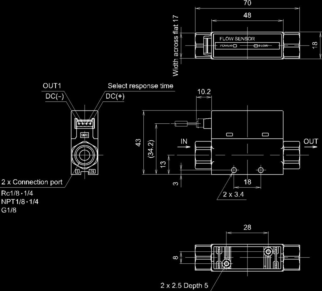
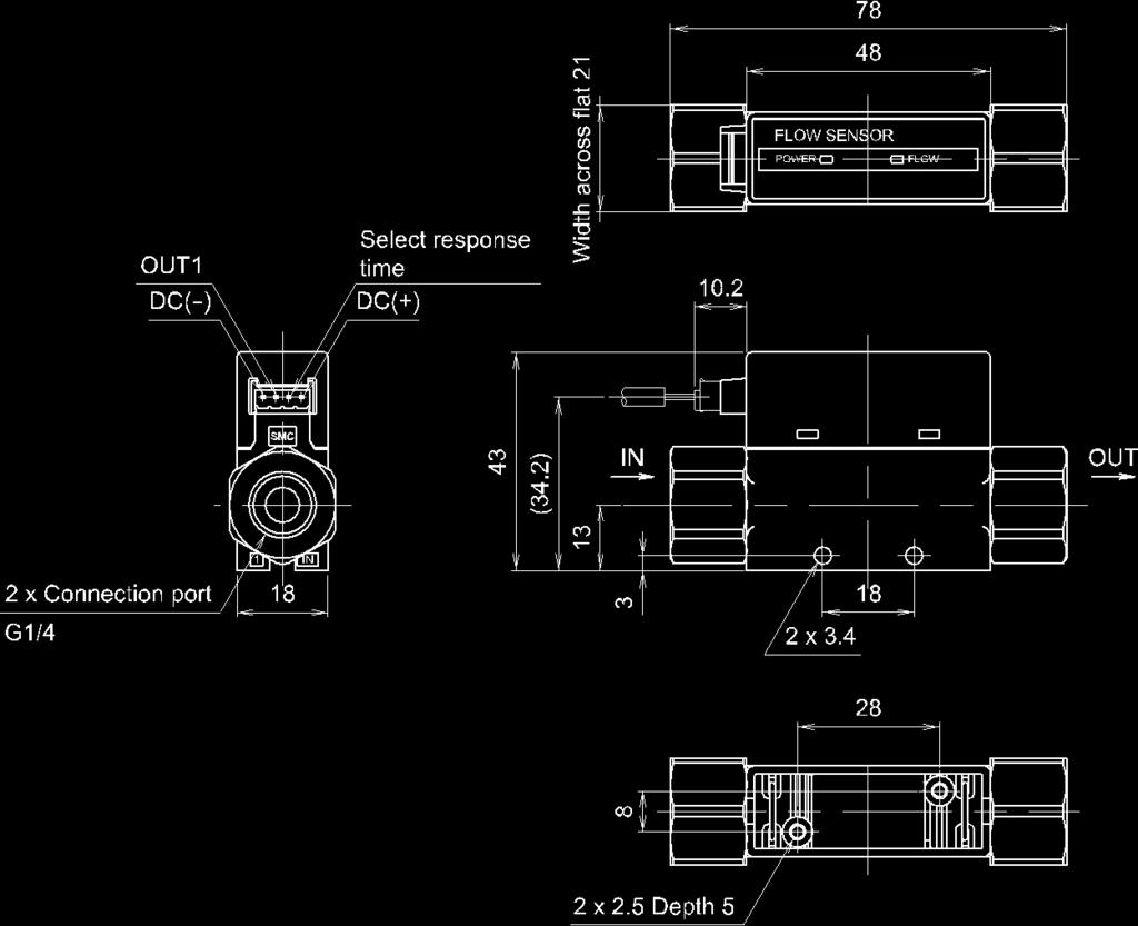
26 Dimensions PFM5 -(N)01/(N)02/F01-1/2-25-
27 PFM5 -(N)01L/(N)02L/F01L-1/2-26-
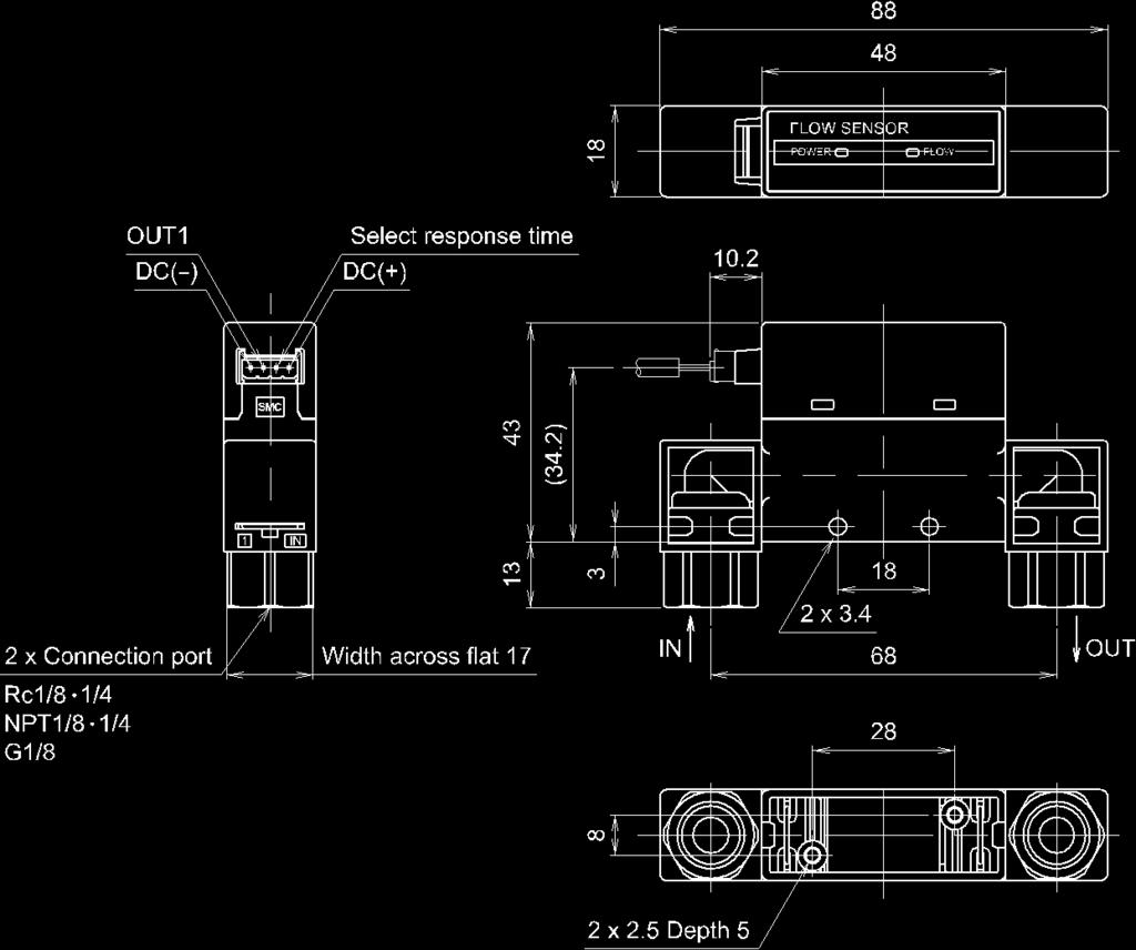
28 PFM5 S-(N)01/(N)02/F01-1/2-27-
29 PFM5 S-(N)01L/(N)02L/F01L-1/2-28-
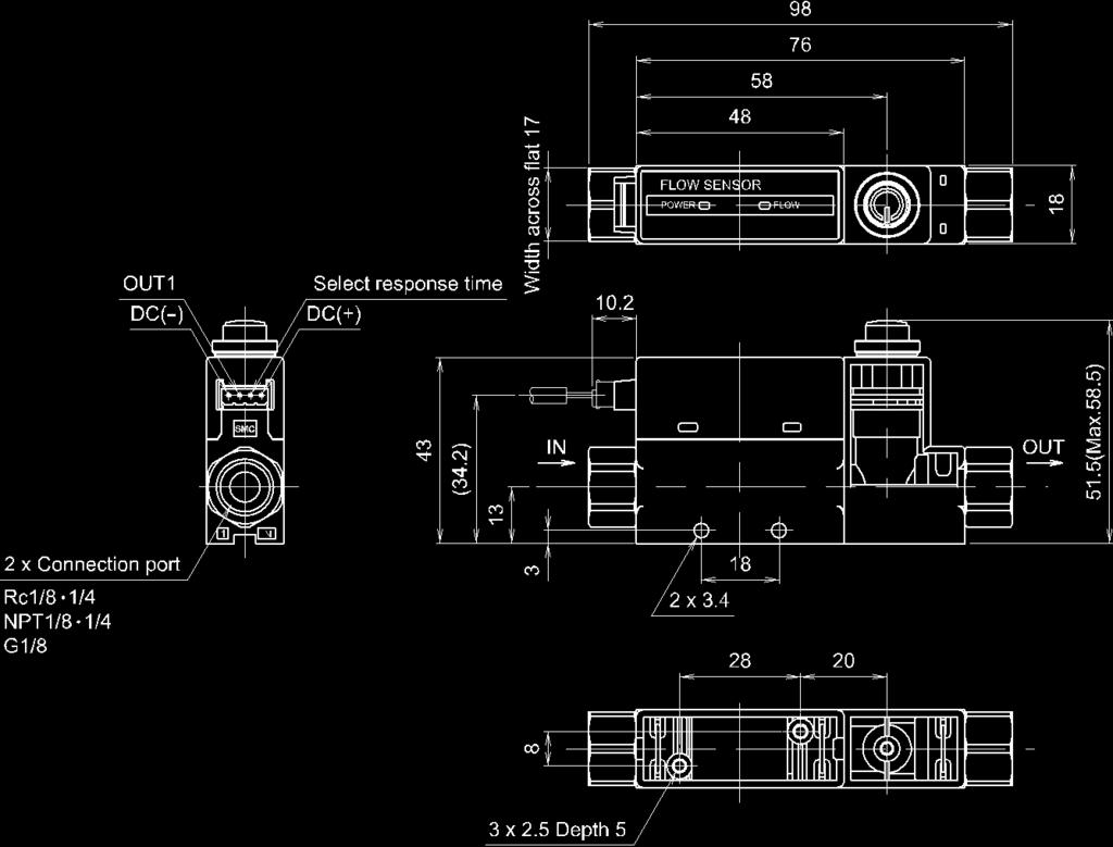
30 PFM5 -F02-1/2-29-
31 PFM5 -F02L-1/2-30-

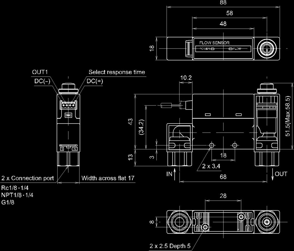
32 PFM5 S-F02-1/2-31-
33 PFM5 S-F02L-1/2-32-

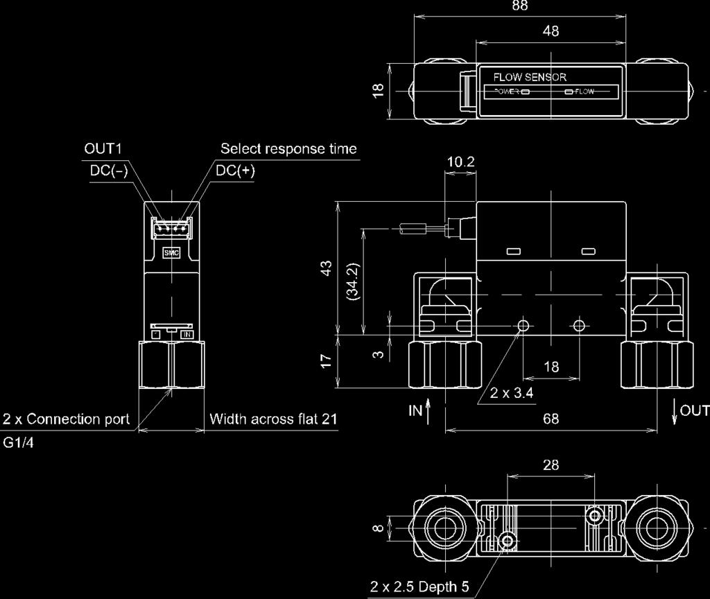
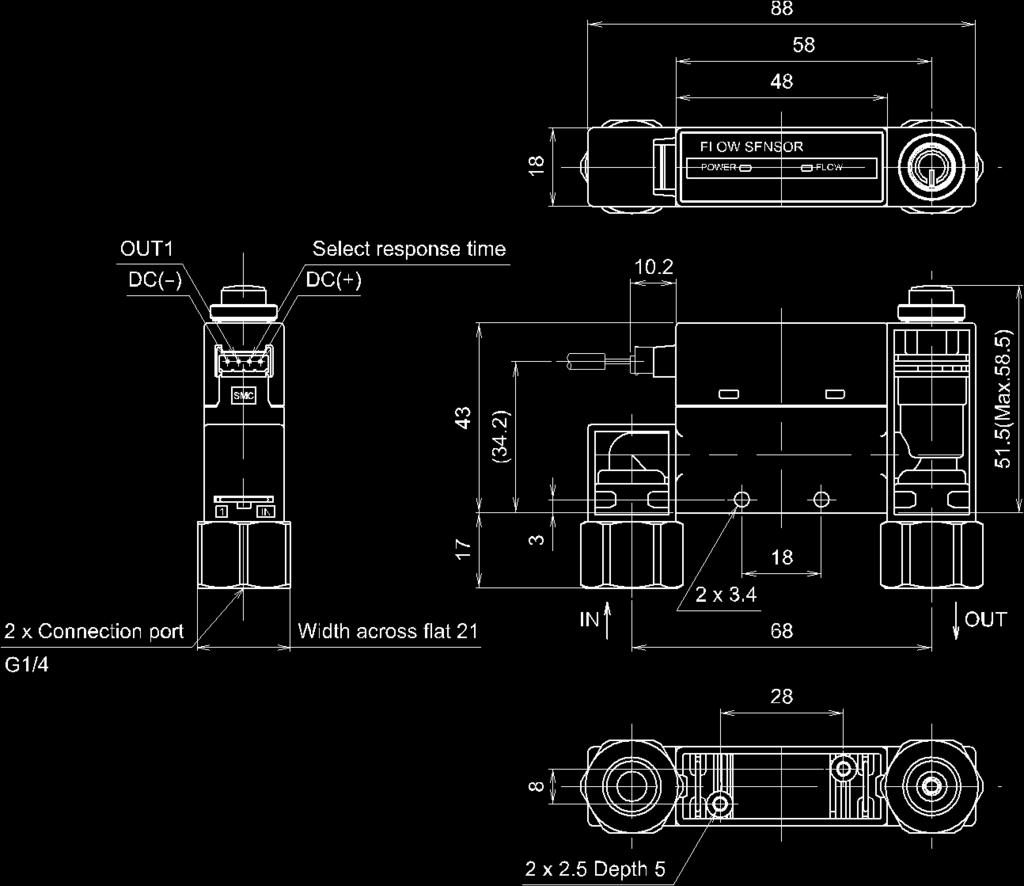
34 PFM5 -C/N -1/2-33-

35 PFM5 -C/N L-1/2-34-

36 PFM5 S-C/N -1/2-35-

37 PFM5 S-C/N L-1/2-36-


 is used, limit it to R3 or less.")
38 Panel cut-out dimensions Flow adjustment valve A None With flow adjustment valve : These are the minimum dimensions for bottom entry piping. If using straight entry piping, the material and tubing need to be taken into consideration when deciding panel cut-out spacing. 2 If a bend (R) is used, limit it to R3 or less. 3: Suitable for panel thickness of 1 to 3.2 mm. Bracket (ZS-33-M) Bracket (ZS-33-MS) -37-


39 Lead wire and connector (ZS-33-D) Connector cover (ZS-33-F) -38-
40 Revision history A: Contents revised in several places. B: Contents revised in several places. C: Modified errors in text. D: Contents are added. E: Contents revised in several places. F: Contents revised in several places. [September 2016] G: Contents are added. [February 2017] , Sotokanda, Chiyoda-ku, Tokyo JAPAN Tel: Fax: URL Note: Specifications are subject to change without prior notice and any obligation on the part of the manufacturer SMC Corporation All Rights Reserved
No.EX -OME0016-A PRODUCT NAME. SI unit. MODEL / Series / Product Number EX140-SDN1
 No.EX -OME0016-A PRODUCT NAME SI unit MODEL / Series / Product Number EX140-SDN1 Table of Contents 1. Safety instructions 2 2. Specifications 7 2-1. General specifications 7 2-2. Electrical ant network
Low Torque Metal Seal Type Rotary Joint. MQR Series
 Doc. No MQR****-OML0002-A. PRODUCT NAME Low Torque Metal Seal Type Rotary Joint MODEL / Series / Product Number MQR Series Contents 1. Contents P1 2. Model / Specifications P2~5 3. Safety Instructions
Pressure Sensor for General Fluids PSE570/573/574
 PRODUCT NAME Pressure Sensor for General Fluids MODEL / Series / Product Number PSE570/573/574 Table of Contents Safety Instructions 2 Model Identification and How to Order 8 Names of Parts of Product
Digital Flow Switch PFM7##
 PRODUCT NAME Digital Flow Switch MODEL / Series / Product Number PFM7## Table of Contents Safety Instructions 2 Model Indication and How to Order 10 Summary of Product parts 13 Definition and terminology
Digital Flow Switch (Integrated display type)
") PRODUCT NAME Digital Flow Switch (Integrated display type) MODEL / Series / Product Number PF2A7## Table of Contents Safety Instructions 2 Model Indication and How to Order 10 Summary of Product parts
PRODUCT NAME Digital Flow Switch (Integrated display type) MODEL / Series / Product Number PF2A7## Table of Contents Safety Instructions 2 Model Indication and How to Order 10 Summary of Product parts
Digital Flow Switch (Remote type monitor unit)
") PRODUCT NAME Digital Flow Switch (Remote type monitor unit) MODEL / Series / Product Number PF2A3## PF2W3## PF2D3## Table of Contents Safety Instructions 2 Model Indication and How to Order 9 Summary of
PRODUCT NAME Digital Flow Switch (Remote type monitor unit) MODEL / Series / Product Number PF2A3## PF2W3## PF2D3## Table of Contents Safety Instructions 2 Model Indication and How to Order 9 Summary of
Digital Flow Switch (Integrated display type)
") PRODUCT NAME Digital Flow Switch (Integrated display type) MODEL / Series / Product Number PF2A7##H Table of Contents Safety Instructions 2 Model Indication and How to Order 10 Summary of Product parts
PRODUCT NAME Digital Flow Switch (Integrated display type) MODEL / Series / Product Number PF2A7##H Table of Contents Safety Instructions 2 Model Indication and How to Order 10 Summary of Product parts
AS Series. 4.0 g. Weight: Approx. 27% lighter. Flow Rate Reproducibility. Larger Knob. Easy Identification of Product Type. 5.5 g.
 Speed Controller with One-touch Fittings In-line In-line Type y Easo t use RoHS Brass Stainless steel Reduces flow setting time! Push-lock type Knob O.D.: Almost doubled! Easy to lock ø9.4 Unlock ø5 Lock
Magnetic Field Resistant 2-color Indication Type Solid State Auto Switch
 PRODUCT NAME Magnetic Field Resistant 2-color Indication Type Solid State Auto Switch MODEL / Series / Product Number D-P3DW(A) * Series Contents Safety Instructions 2 Model Indication Method 8 Names and
SI unit for AS-Interface EX250-SAS#
 PRODUCT NAME SI unitfor AS-Interface MODEL / Series / Product Number EX250-SAS# Table of Contents Safety Instructions 2 Product Outline 8 Model Indication and How to Order 9 Summary of Product elements
High Vacuum Solenoid Valve PRODUCT NAME. XSA Series MODEL/ Series
 Doc. No. High Vacuum Solenoid Valve PRODUCT NAME XSA Series MODEL/ Series Thank you for purchasing this SMC product. Be sure to read this Operation Manual carefully and understand its contents before operating
Pressure Relief 3 Port Valve With Locking Holes
 Doc. No. VH*-OMQ0023-B PRODUCT NAME Pressure Relief 3 Port Valve With Locking Holes MODEL / Series / Product Number VHS20-(F,N)01~02A,B(-B,S)(-K,R,Z) VHS30-(F,N)02~03A,B(-B,S)(-K,R,Z) VHS40-(F,N)02~04A,B(-B,S)(-K,R,Z)
High Vacuum Solenoid Valve PRODUCT NAME. XSA Series MODEL/ Series
 Doc. No. High Vacuum Solenoid Valve PRODUCT NAME XSA Series MODEL/ Series Thank you for purchasing this SMC product. Be sure to read this Operation Manual carefully and understand its contents before operating
Solid State Auto Switch D-M9#A#
 PRODUCT NAME Solid State Auto Switch MODEL / Series / Product Number D-M9#A# Contents Safety Instructions 2 Model Indication and How to Order 8 Summary of Product parts 10 Summary of Product parts 10 Definition
Digital Pressure Switch
 PRODUCT NAME Digital Pressure Switch MODEL / Series / Product Number ZSE10(F) ISE10 Table of Contents Safety Instructions 2 Model Indication and How to order 9 Summary of Product parts 11 Definition and
This filter enables direct exhaust of air in a clean room! (Cleanliness class 4*: ISO ) (* Based on SMC s measuring conditions.
 (* Based on SMC s measuring conditions.") Clean Exhaust Filter This filter enables direct exhaust of air in a clean room! (Cleanliness class 4*: ISO14644-1) (* Based on SMC s measuring conditions.) Air can be directly exhausted in a clean room
Clean Exhaust Filter This filter enables direct exhaust of air in a clean room! (Cleanliness class 4*: ISO14644-1) (* Based on SMC s measuring conditions.) Air can be directly exhausted in a clean room
Doc. no.vn-omm0001-c. Coolant valve PRODUCT NAME. VNC/VNH Series MODEL / Series / Product Number
 Doc. no. Coolant valve PRODUCT NAME VNC/VNH Series MODEL / Series / Product Number Contents Safety Instructions ---------------------------------------------------------------------------------- 2,3 Precautions
Digital pressure switch for energy-saving control ejector
 PRODUCT NAME Digital pressure switch for energy-saving control ejector MODEL / Series / Product Number ZK2-ZSV####-A Table of Contents Safety Instructions 2 Model indication and How to order 9 Summary
1.8 w Port Solenoid Valve Direct Operated Poppet Type. New. Series VT307 CAT.ES11-107A. Power consumption
 Port Solenoid Valve Direct Operated Poppet Type Power consumption Vacuum applications New [Option] RoHS 4 Standard wtype (Existing product: 4.8 W) 0. kpa Energy-saving type.8 w (Existing product: W) A
Digital Gap Checker. ISA3 series
 PRODUCT NAME Digital Gap Checker MODEL / Series / Product Number ISA3 series Table of Contents 1 Before Use Safety Instructions 2 2 About this product Features 7 Model Indication and How to Order 8 Summary
Digital Pressure Switch
 PRODUCT NAME Digital Pressure Switch MODEL / Series / Product Number ZSE80(F) ISE80(H) Table of Contents Safety Instructions 2 Model Indication and How to order 9 Summary of Product parts 10 Definition
Digital Gap Checker. ISA3 series
 PRODUCT NAME Digital Gap Checker MODEL / Series / Product Number ISA3 series Table of Contents 1 Before Use Safety Instructions 2 2 About this product Features 7 Model Indication and How to Order 8 Summary
SI unit for Ethernet POWERLINK
 PRODUCT NAME SI unit for Ethernet POWERLINK MODEL / Series / Product Number EX260 Series Table of Contents Safety Instructions 2 Model Indication and How to Order 8 Summary of Product elements 9 Installation
SI unit for EtherCAT. EX260 Series
 PRODUCT NAME SI unit for EtherCAT MODEL / Series / Product Number EX260 Series Contents Safety Instructions 2 How to Order 7 Summary of Product elements 8 Installation and Cabling 9 Installation 9 Connecting
Doc. no.vn -OMA0002-D. Process valve PRODUCT NAME. VNA Series MODEL / Series / Product Number
 Doc. no. Process valve PRODUCT NAME VNA Series MODEL / Series / Product Number Contents Safety Instructions ---------------------------------------------------------------------------------- 2,3 Design
Doc.No.LV50***-OMQ0004-D. Product. Electromagnetic Digital flow switch. Model/ Series/ Product No. LFE#### SMC Corporation
 Doc. Product Electromagnetic Digital flow switch Model/ Series/ Product No. LFE#### SMC Corporation Contents Safety Instructions 2 Model Indication and How to Order 11 Summary of Product Parts 13 Definitions
Air Catch Sensor ISA2
 No.PS##-OMF0007-C PRODUCT NAME Air Catch Sensor MODEL / Series / Product Number ISA2 Table of Contents Safety Instructions 2 Model Indication and How to Order 11 Summary of Product parts 13 Definition
Doc.No.LV50***-OMQ0004-B. Product. Electromagnetic Type Digital flow switch. Model/ Series/ Product No. LFE#### SMC Corporation
 Doc. Product Electromagnetic Type Digital flow switch Model/ Series/ Product No. LFE#### SMC Corporation Contents Safety Instructions 2 Model Indication and How-to-Order 11 Summary of product parts 13
Coolant valve. SGC/SGH Series
 Doc. no. PRODUCT NAME Coolant valve MODEL / Series / Product Number SGC/SGH Series Contents Safety Instructions ------------------------------------------------------------------------------------- 2,3
Solid State Auto Switch
 PRODUCT NAME Solid State Auto Switch MODEL / Series / Product Number D-M9## D-M9#W# Contents Safety Instructions 2 Model Indication and How to Order 9 Summary of Product parts 10 Definition and terminology
EX##-OMN0011-A. SI unit for EtherCAT PRODUCT NAME. EX260 Series MODEL/ Series
 EX##-OMN0011-A SI unit for EtherCAT PRODUCT NAME EX260 Series MODEL/ Series Contents Safety Instructions 2 How to Order 7 Summary of Product elements 8 Installation and Cabling 9 General instructions on
ITVX Series. Stepless control of air pressure proportional to an electrical signal. Supply pressure: 5.0 MPa
 5.0 MPa Maximum Supply Pressure High Pressure Electro-Pneumatic Regulator X Series This product is only for blowing gas. This product does not have sufficient pressure control for other applications (driving,
 2-Colour Display Type High-Precision Digital Pressure Switch Series ZSE30/ISE30 How to Order Option 1 Without lead wire Nil Lead wire with connector (Lead wire length: 2m) L For positive pressure For vacuum/low
Speed Controller with Indicator
 Speed Controller with Indicator Numerical indication of handle rotation for flow rate reduces flow setting time and setting errors! Indicator window Body size Body size or larger Indicator window Number
(Actual size) 2 switches 10 switches. Push Adjust to the set-value by the or button.
 2 switches 10 switches. Push Adjust to the set-value by the or button.") Digital Pressure Switch RoHS compliant Low profile 9.8 mm (Actual size) 13.5 mm 53.4 mm Vertical mounting space reduced to approx.! 1 2 Reduced in depth! 26.1 mm Can copy to up to 1 switches simultaneously.
Digital Pressure Switch RoHS compliant Low profile 9.8 mm (Actual size) 13.5 mm 53.4 mm Vertical mounting space reduced to approx.! 1 2 Reduced in depth! 26.1 mm Can copy to up to 1 switches simultaneously.
Low Differential Pressure Sensor ±1% F.S.
 CAT.ES100-49 A Low Differential Pressure Sensor Rated differential pressure range: 0 to 2 kpa Accuracy: ±1% F.S. LED display to confirm energization Series PSE550 Proof pressure: 65kPa Output: 1 to 5VDC
Trimmer Auto Switch D-F7K/D-Y7K D-RNK/D-RPK
 PRODUCT NAME Trimmer Auto Switch MODEL / Series / Product Number D-F7K/D-Y7K D-RNK/D-RPK Table of Contents Safety Instructions 2 Model Indication and How to Order 9 Summary of Product parts 10 Definition
Doc.No.LV50***-OMQ0002-E. Product Name. Electromagnetic Digital Flow Switch. Model/ Series/ Product Number LFE#### SMC Corporation
 Doc. Product Name Electromagnetic Digital Flow Switch Model/ Series/ Product Number LFE#### SMC Corporation Contents Safety Instructions 2 Model Indication and How to Order 11 Summary of Product Parts
0.1 mm. Actuator Position Sensor. D-MP Series. Actuator stroke position is output with an analog signal. Repeatability IP67.
 Actuator Position Sensor Actuator stroke position is output with an analog signal. IP67 Repeatability 0.1 mm (Varies depending on the operating conditions.) Analog output 4 measurement ment ranges Voltage
Doc. No.VT307 -OMH0001-C. 3 Port Direct Operated Solenoid Valve PRODUCT NAME. VT307 Series MODEL/ Series
 Doc. No. 3 Port Direct Operated Solenoid Valve PRODUCT NAME VT307 Series MODEL/ Series Contents Safety Instructions ------------------------------------------------------------------------------- 2,3 Precautions
Trimmer Auto Switch D-M9K/D-F7K/D-Y7K D-RNK/D-RPK
 PRODUCT NAME Trimmer Auto Switch MODEL / Series / Product Number D-M9K/D-F7K/D-Y7K D-RNK/D-RPK Table of Contents Safety Instructions 2 Model Indication and How to Order 9 Summary of Product parts 10 Definition
2-Color Display Digital Pressure Switch. Rated Pressure Metal Body Type (ISE75H) 2-color digital. Functions
 2-color digital. Functions") Series ISE70/75/75H NPN/PNP open collector 2 outputs added. Cut-to-zero display function added. For General Fluids For Air 2-Color Display (Green/Red) Selectable from four patterns ON Red Green Red Green
Series ISE70/75/75H NPN/PNP open collector 2 outputs added. Cut-to-zero display function added. For General Fluids For Air 2-Color Display (Green/Red) Selectable from four patterns ON Red Green Red Green
Digital Flow Switch (Sensor Part) Operation Manual
 Operation Manual") Digital Flow Switch (Sensor Part) Operation Manual For Air PF2A 50/5 Series PF2A 5/ 52/ 55 Series For Water PF2W /520/50 Series PF2W 5 Series For Water (High Temperature Fluid Type) PF2W T/520T/50T Series
Digital Flow Switch (Sensor Part) Operation Manual For Air PF2A 50/5 Series PF2A 5/ 52/ 55 Series For Water PF2W /520/50 Series PF2W 5 Series For Water (High Temperature Fluid Type) PF2W T/520T/50T Series
2-Color Display Digital Pressure Switch. NPN/PNP open collector 2 outputs added. Cut-to-zero display function added. Rated Pressure Metal Body Type
 Series ISE70/75/75H New NPN/PNP open collector 2 outputs added. Cut-to-zero display function added. For General Fluids For Air 2-Color Display (Green/Red) Selectable from four patterns ON Red Green Red
l/min (Comparison under Nozzle diameter: ø0.3, Vacuum pressure: 60 kpa) New
 New") Flow Sensor Suction check of very small workpieces This flow sensor enables precise suction. Pressure sensor Flow sensor 60 58 kpa Before suction During suction Before suction Pressure difference Small
Flow Sensor Suction check of very small workpieces This flow sensor enables precise suction. Pressure sensor Flow sensor 60 58 kpa Before suction During suction Before suction Pressure difference Small
ISE7 /7 G Series CAT.ES B. MPa/1.6 MPa 1.0. MPa/2.0 MPa. MPa/10 MPa
 3-Screen Display High-Precision Digital Pressure Switch Air General Fluids 1.0 ISE70 ISE71 MPa/1.6 MPa 1.0 ISE70G ISE75G MPa/2.0 MPa 5.0 ISE76G ISE77G MPa/10 MPa It is possible to change the settings while
Technical information for LFU20-Z07-3A-X2
 Technical information for LFU20-Z07-3A-X2 Ultrasonic flow sensor and flow controller Applications: closed-loop flow control. Also requires fluid regulator (separate part) Ultrasonic flow sensor IN18796_LFU
Doc. no.ck1*-om0066p. PRODUCT NAME Clamp Cylinder. MODEL / Series / Product Number
 Doc. no.ck1*-om0066p PRODUCT NAME Clamp Cylinder MODEL / Series / Product Number CK1*40&63-**Z CKG1*40&63-**Z-** CKP1*40&63-**Z-** Contents Safety Instructions P2 1. Specifications P4 1-1. Specifications
2-Color Display High-Precision Digital Pressure Switch
 2-Color Display High-Precision Digital Pressure Switch Series ZSE3/ISE3 2-color digital display allows you to choose the setting according to your application requirements. 4 different display settings
Regulator Valve. VEX1 Series
 Doc. no. PRODUCT NAME Regulator Valve MODEL / Series / Product Number VEX1 Series Contents Safety Instructions ---------------------------------------------------------------------------------- 2,3 Precautions
Doc. no.mx*-omp0038-d PRODUCT NAME AIR SLIDE TABLE. MODEL / Series / Product Number
 Doc. no.mx*-omp0038-d PRODUCT NAME AIR SLIDE TABLE MODEL / Series / Product Number MXQ6(A,B)-**Z* MXQ8(A,B,C)-**Z* MXQ12(A,B,C)-**Z* MXQ16(A,B)-**Z* MXQ20(A,B)-**Z* MXQ25(A)-**Z* Contents 1. Pr oduc t
Doc. No.VG300 -OMH0002-B. 3 Port Solenoid Valve PRODUCT NAME. VG342 Series MODEL/ Series
 Doc. No. 3 Port Solenoid Valve PRODUCT NAME VG342 Series MODEL/ Series Contents Safety Instructions ---------------------------------------------------------------------------- 2,3 Precautions on Design
2-Color Display High-Precision Digital Pressure Switch Series ZSE40A(F)/ISE40A
/ISE40A") 2-Color Display High-Precision Digital Pressure Switch Series ZSEA(F)/ISEA New M8 connector type RoHS IP65 Applicable fluid Air, Non-corrosive gas, Non-flammable gas Can copy to up to 10 switches simultaneously.
2-Color Display High-Precision Digital Pressure Switch Series ZSEA(F)/ISEA New M8 connector type RoHS IP65 Applicable fluid Air, Non-corrosive gas, Non-flammable gas Can copy to up to 10 switches simultaneously.
Doc. No.VQ1000V-OMM0002-B. Solenoid Valve PRODUCT NAME. VQ1000/2000 Series (PILOT VALVE : V100) MODEL/ Series
 MODEL/ Series") Doc. Solenoid Valve PRODUCT NAME VQ1000/2000 Series (PILOT VALVE : V100) MODEL/ Series Contents Safety Instructions ---------------------------------------------------------------------------- 2,3 Precautions
Doc. Solenoid Valve PRODUCT NAME VQ1000/2000 Series (PILOT VALVE : V100) MODEL/ Series Contents Safety Instructions ---------------------------------------------------------------------------- 2,3 Precautions
Doc. No.VQ4000V-OMV0001. Solenoid Valve PRODUCT NAME. VQ4000/5000 (Pilot Valve V100) MODEL/ Series
 MODEL/ Series") Doc. No. Solenoid Valve PRODUCT NAME VQ4000/5000 (Pilot Valve V100) MODEL/ Series Contents Safety Instructions ---------------------------------------------------------------------------- 2,3 Precautions
Doc. No. Solenoid Valve PRODUCT NAME VQ4000/5000 (Pilot Valve V100) MODEL/ Series Contents Safety Instructions ---------------------------------------------------------------------------- 2,3 Precautions
69% 30.5 mm 16 mm. Compact Guide Cylinder. Compact. lighter 0.32 kga0.1 kg (Compared with the current MGP-Z series, ø16, 10 mm stroke) Weight
 Weight") Compact Guide Cylinder ø12, ø16, ø20, ø25, ø32, ø40, ø50, ø63, ø80, ø100 RoHS Compact Overall length shortened New s ø80, ø100 added. Port thread types NPT, G added. Height shortened JMGP ø32 25 mm stroke
Compact Guide Cylinder ø12, ø16, ø20, ø25, ø32, ø40, ø50, ø63, ø80, ø100 RoHS Compact Overall length shortened New s ø80, ø100 added. Port thread types NPT, G added. Height shortened JMGP ø32 25 mm stroke
No. MGP*-OM0047P-B PRODUCT NAME. Remodeled. MODEL / Series / Product Number. Series MGP-Z
 No. MGP*-OM0047P-B PRODUCT NAME Remodeled MODEL / Series / Product Number Series MGP-Z Contents Safety Instructions 2 Product feature 4 1. How to Order 5 2. Model 5 3. Specifications 5 4. Standard strokes
Series ZSE30/ISE30. High Precision, 2-color Display Digital Pressure Switch. With One-touch fittings are newly introduced. PSE
 High Precision, 2-color Display Digital Pressure Switch Series SE30/ISE30 SE ISE PSE I SE3 PS I SE 1 2 SP ISA2 IS SM PF2 IF Data With One-touch fittings are newly introduced. Straight type Elbow type 16-2-1
Clean Air Module. Digital flow switch Regulator ON/OFF valve Restrictor Filter
 Clean Air Module Series Digital flow switch Regulator ON/OFF valve Restrictor Filter Modularizes clean equipment (Reduced piping man-hours/space-saving). Easily obtains clean air. Built-in one-touch fitting
Lock unit MWB*32&100-UT-* MWB*32&100TN-UT-* MWB*32&100TF-UT-*
 Doc. no.mwb*-om0078q PRODUCT NAME Lock unit MODEL / Series / Product Number MWB*32&100-UT-* MWB*32&100TN-UT-* MWB*32&100TF-UT-* Contents Safety Instructions P. 3 1. Product Specifications P. 5 1-1. Lock
2-Color Display Digital Flow Switch
 -Color Display Digital Flow Switch Series Flow rate range:, 5, 5, l/min. Minimum unit setting:. l/min. (. l/min when the flow rate range is 5, 5, l/min.) Repeatability: ±%F.S. or less Grease-free Flow
9.8 mm. Digital Pressure Switch. 3-step setting. RoHScompliant. Series ZSE10(F)/ISE10. Vertical mounting space reduced to approx.! Reduced in depth!
/ISE10. Vertical mounting space reduced to approx.! Reduced in depth!") Digital Pressure Switch Series ZSE1(F)/ISE1 Low profile 26.1mm 9.8 mm 13.5 mm 53.4 mm Reduced in depth! (Actual size) RoHScompliant Vertical mounting space reduced to approx.! 1 2 Position Detection Switch
Digital Pressure Switch Series ZSE1(F)/ISE1 Low profile 26.1mm 9.8 mm 13.5 mm 53.4 mm Reduced in depth! (Actual size) RoHScompliant Vertical mounting space reduced to approx.! 1 2 Position Detection Switch
High Vacuum L Type Valve
 Doc. no. PRODUCT NAME High Vacuum L Type Valve MODEL / Series / Product Number XLFV-2 Series Contents Safety Instructions - - - - - - - - - - - - - - - - - - - - - - - - - - - - 2 1. Product Specific Precautions
ITVH Series. 3.0 MPa Maximum Supply Pressure High Pressure Electro-Pneumatic Regulator. 3.0 MPa 0.2 to 2.0 MPa. 3 W or less L /min (ANR)*
*") 3.0 MPa Maximum Supply Pressure High Pressure Electro-Pneumatic Regulator ITVH Series ARJ RoHS Maximum supply pressure Set pressure range Stability 3.0 MPa 0.2 to 2.0 MPa ARX AMR Stepless control of air
3.0 MPa Maximum Supply Pressure High Pressure Electro-Pneumatic Regulator ITVH Series ARJ RoHS Maximum supply pressure Set pressure range Stability 3.0 MPa 0.2 to 2.0 MPa ARX AMR Stepless control of air
49.5 mm Overall. 30 mm MXZ ø20. Compact. Compact Cylinder with Linear Guide. MXZ Series CAT.ES20-236A. ø12, ø16, ø20, ø25. MXZ ø20, 10 mm stroke.
 Compact Cylinder with Linear Guide ø12, ø16, ø20, ø25 RoHS Compact 49.5 mm Overall length MXZ ø20, 10 mm stroke 30 mm MXZ ø20 Width Design and assembly time is reduced due to integration of a linear guide
High Vacuum Solenoid Valve. 25% reduction. Max. Weight. 18% * lighter. Max. * XSA2-2 AC 100 V, 200 V, 110 V, 220 V, 240 V, 48 V, 24 V, 230 V DC
 Normal lose High Vacuum Solenoid Valve Minimum operating pressure * 1x10 6 Pa(abs) * OUT side Leakage Internal 1.3 x10 9 Pa m3/s Note) Note) Except grommet/ RoHS External 1.3 x10 11 Pa m3/s 2 types of
Series 10-ZSE40A(F)/10-ISE40A
/10-ISE40A") Series 10-ZSEA(F)/10-ISEA RoHS 2-Color Display High Precision Digital Pressure Switch How to Order For positive pressure Clean series For vacuum/ compound pressure 01 N01 W1 10 Rated pressure range ISEA
Series 10-ZSEA(F)/10-ISEA RoHS 2-Color Display High Precision Digital Pressure Switch How to Order For positive pressure Clean series For vacuum/ compound pressure 01 N01 W1 10 Rated pressure range ISEA
Direct Operated 3-port solenoid valve
 Doc. No. PRODUCT NAME Direct Operated 3-port solenoid valve MODEL/ Series Series: VT315 Contents Safety Instructions --------------------------------------------------------------------------- 2,3 Precautions
Doc. no.cm2*-om0064p. PRODUCT NAME Air cylinder. MODEL / Series / Product Number
 Doc. no.cm2*-om0064p PRODUCT NAME Air cylinder MODEL / Series / Product Number C*M2**-*Z C*M2**-*Z-XC85 C*M2**-*Z-X446 Contents Safety Instructions P2 1. Specifications P4 1-1. Specifications 2. Installation
3 Port 3 Position Valve
 Port Position Valve Pilot Solenoid ir Operated ohs Intermediate stopping of cylinders * up to ø15 is possible. Pilot solenoid Manifold ir operated * For VEX 4, 00 mm/s, horizontal movement Power consumption:
Electro-pneumatic proportional valve
 Doc. no. PRODUCT NAME Electro-pneumatic proportional valve MODEL / Series / Product Number VEP/VEF/VEA/VER Series Contents Safety Instructions ----------------------------------------------------------------------------------
2-Color Display Digital Pressure Switch. Rated Pressure Metal Body Type. MPa MPa (ISE75H) 2-color digital. Functions
 2-color digital. Functions") -Color Display Digital Pressure Switch /75/75H Series NPN/PNP open collector outputs added. Zero-cut off display function added. For General Fluids For Air Rated Pressure Metal Body Type 0 5 (E75) () -Color
-Color Display Digital Pressure Switch /75/75H Series NPN/PNP open collector outputs added. Zero-cut off display function added. For General Fluids For Air Rated Pressure Metal Body Type 0 5 (E75) () -Color
2-Color Display High-Precision Digital Pressure Switch
 2-Color Display High-Precision Digital Pressure Switch Settings can be copied to up to 1 slave sensors at once. The settings of the master sensor can be copied to the slave sensors. Reduced setting efforts
45% 6.5 mm. 6 mm. 4 mm. Compact Cylinder. Compact. lighter. JCQ Series CAT.ES20-239C. Weight. ø12, ø16, ø20, ø25, ø32, ø40, ø50, ø63, ø80, ø100
 Compact Cylinder ø12, ø16, ø20, ø25, ø32, ø40, ø50, ø63, ø80, ø100 RoHS Compact Both ends tapped mounting added. New s ø80, ø100 added. Port thread types NPT, G added. Overall length shortened 10 mm stroke
Technical Specifications
 No.:EX##-OMG0007 Technical Specifications Product name : SI unit Model : EX250-SAS7 EX250-SAS9 Contents 1. Safety 2. Specifications 2-1 General specification 2-2 Communication specification 2-3 Electrical
AV2000-A/3000-A/4000-A/5000-A
 Soft Start-up Valve Start-up valve for low speed air supply to gradually raise initial pressure in an air system and for quick exhaust by cutting off air supply Power consumption: 0.35 W * At 12/24 VDC
Doc. No. IZ -OML0002-B OPERATION MANUAL. Ionizer PRODUCT NAME:
 Doc. No. IZ -OML0002-B OPERATION MANUAL PRODUCT NAME: MODEL: Ionizer IZN10 Series Read this operation manual carefully to understand before installation and operation. Pay extra attention on the clause
HEAVY DUTY STOPPER CYLINDER
 Doc. no. RS2H-OM0012P- B PRODUCT NAME HEAVY DUTY STOPPER CYLINDER MODEL / Series / Product Number RS2H Series (φ50 to φ80) Contents Safety Instructions P.2 1. Specifications P.4 1-1. Cylinder specifications
Vacuum pump system type
 type VS*P Vacuum component C O N T E N T S Series variation 166 20 mm width universal type (/M) 168 10.5 mm width universal type (/M) 184 31.5 mm width discrete type (VSQP) 214 11 mm pitch manifold dedicated
RJ M8 size absorption time. Energy (J) RJ-L type. With cap. Short stroke type
 RJ-L type. With cap. Short stroke type") Shock Absorber Soft type Stops transported objects softly % reduced absorption time Unique mechanism to achieve a variable sectional area of the fluid channel proportional to the stroke (compared with
Shock Absorber Soft type Stops transported objects softly % reduced absorption time Unique mechanism to achieve a variable sectional area of the fluid channel proportional to the stroke (compared with
10 PSE53 0 M5. Port size. M5 x 0.8 ø6 reducer 1/4-inch reducer. the cable at the time of shipment. 10-PSE to -101 kpa
 Series 0-PSE50 Remote type pressure sensor How to Order Clean series 0 PSE5 0 M5 Pressure sensing range Option 0 2 High pressure [0 to MPa] Vacuum [0 to 0 kpa] Low pressure [0 to 0 kpa] Compound pressure
Two Hand Control Valve
 Two Hand Control Valve Series n output is available through synchronized, twohanded operation (within 0.5 s)! Conforming to EN574 RoHS (Interchangeable with XT92-67 ) Example of a basic circuit diagram
Rotary Actuators Precautions 1 Be sure to read this before handling.
 Precautions 1 1. Confirm the specifications. Products represented in this catalog are designed only for use in compressed air systems (including vacuum). Do not operate at pressures or temperatures, etc.,
10 switches simultaneously. The settings of the master sensor (source of copy) can be copied to the slave sensors. Reducing setting labor
 can be copied to the slave sensors. Reducing setting labor") 2-Color Display High-Precision Digital Pressure Switch ZSE ISE RoHS ZSE ISE IP65 ZSE40 ISE40 M8 connector type ZSE10 ISE10 ISE70 ZSE80 ISE80 PS ISA3 ISA2 ISE35 Applicable Air, Non-corrosive gas, Non-flammable
2-Color Display High-Precision Digital Pressure Switch ZSE ISE RoHS ZSE ISE IP65 ZSE40 ISE40 M8 connector type ZSE10 ISE10 ISE70 ZSE80 ISE80 PS ISA3 ISA2 ISE35 Applicable Air, Non-corrosive gas, Non-flammable
Operation Manual. Model name. MRHQ Rotary Gripper. Part number / Series MRHQ10,16,20,25
 Doc. no. MRHQ-OM00002-C Operation Manual Model name MRHQ Rotary Gripper Part number / Series MRHQ10,16,20,25 - Install and operate the product only after reading the Operation Manual carefully and understanding
Soft Start-up Valve. AV2000/3000/4000/5000 Series
 Soft Start-up Valve V000/000/000/000 Series [Option] C- R- W- C R - W - Start-up valve for low speed air supply to gradually raise initial pressure in an air system and for quick exhaust by cutting off
1.3 x % reduction 18% High Vacuum Solenoid Valve. XSA Series CAT.ES140-7B. 5 to 60 C
 Normal lose igh Vacuum Solenoid Valve Minimum operating pressure x0 * 6 Pa(abs) * OUT side * * Excluding grommet/ RoS Leakage Internal.3 x0 9 Pa m3/s External.3 x0 Pa m3/s Max. Max. Power consumption 5%
Trimmer Auto Switch Series D- 7K/D-R K
 CAT.ES0-180 B Trimmer Auto Switch Series D- K/D-R K Large work piece OUT1 and OUT are adjustable separately. OUT1 Trimmer OUT Trimmer OUT Medium work piece Small work piece Operating range of sensor (LED
SG-B1 SERIES / SG-A1 SERIES
 643 Door with Solenoid Interlock / Door Ultra-slim SG-B1 SERIES / SG-A1 SERIES Related Information General terms and conditions... F-7 General precautions... P.1501 PHOTO PHOTO Conforming to Machine &
Differential Pressure Transmitter
 Specifications/Instructions Differential Pressure Transmitter General Model PY9000D is a differential pressure transmitter that uses a ceramic cantilever sensor. Deflection of the ceramic cantilever caused
Series ITV009. Compact Vacuum Regulator ITV IITV00 02 n. RoHS. How to Order
 Courtesy of CMA/Flodyne/Hydradyne Motion Control Hydraulic Pneumatic Electrical Mechanical (8) 6-8 www.cmafh.com 7 For single unit and single unit for manifold ITV 9 Pressure range 9 kpa Built-in One-touch
3-step setting. 2-Color Display High-Precision Digital Pressure Switch. Series ZSE30A(F)/ISE30A. Added vacuum range.
/ISE30A. Added vacuum range.") 2-Color Display High-Precision Digital Pressure Switch Series ZSE3A(F)/ISE3A RoHS Can copy to up to 1 switches simultaneously. The settings of the master sensor can be copied to the slave sensors. Reducing
2-Color Display High-Precision Digital Pressure Switch Series ZSE3A(F)/ISE3A RoHS Can copy to up to 1 switches simultaneously. The settings of the master sensor can be copied to the slave sensors. Reducing
Read and understand this manual for safely usage.
 TS02-0180 INSTRUCTION MANUAL FOR AIR BUBBLER SYSTEM LEVEL MEASUREMENT MODEL:LA100 MODEL:LA110 MODEL:LA1000 Read and understand this manual for safely usage. This manual describes the product of standard
Set value (Threshold value) Bottom value. *2 Further reduced by approx. 60% in power-saving mode (For 20 series)
 Bottom value. *2 Further reduced by approx. 60% in power-saving mode (For 20 series)") 3-Screen Display High-Precision Digital Pressure Switch New Added Variations! For general fluids IP65 2 outputs Analog output Setting is possible while checking Main screen the measured value. Sub screen
3-Screen Display High-Precision Digital Pressure Switch New Added Variations! For general fluids IP65 2 outputs Analog output Setting is possible while checking Main screen the measured value. Sub screen
2-colour display. Digital Pressure Switch. Stainless diaphragm Oil-free (Single-layer diaphragm structure) IP65 compliant
 IP65 compliant") -Colour Display Digital Pressure Switch Stainless diaphragm Oil-free (Single-layer diaphragm structure) Sensor parts: Stainless steel 6 Fitting parts: Stainless steel 4 The sensor and fitting parts can
-Colour Display Digital Pressure Switch Stainless diaphragm Oil-free (Single-layer diaphragm structure) Sensor parts: Stainless steel 6 Fitting parts: Stainless steel 4 The sensor and fitting parts can
Series ITV0000. Compact Electro-pneumatic Regulator ITV N. IITV00 02 n. How to Order F.R.L. AV AU AF AR IR VEX AMR ITV IC VBA VE VY1 G PPA AL
 Compact Electro-pneumatic Regulator Series For single unit and single unit for manifold Pressure range 9 Option. MPa. MPa.9 MPa kpa Option How to Order N Power supply voltage 24 VDC ±% 2 to VDC Option
Pneumatic components (Electro pneumatic Regulator) Safety Precautions. 3 When releasing secondary control pressure,
 Safety Precautions. 3 When releasing secondary control pressure,") Pneumatic components (Electro pneumatic Regulator) Safety Precautions Read this before starting use. Please refer to Intro 43 for general details on the pneumatic components, and to " Precautions" in this
Pneumatic components (Electro pneumatic Regulator) Safety Precautions Read this before starting use. Please refer to Intro 43 for general details on the pneumatic components, and to " Precautions" in this
SI unit for DeviceNet TM PRODUCT NAME. SI unit EX250-SDN1 EX250-SDN1-X102
 SI unit for DeviceNet TM PRODUCT NAME SI unit MODEL / Series / Product Number EX250-SDN1 EX250-SDN1-X102 Contents Safety Instructions 2 Product Summary 7 Model indication and How to order 8 Summary of
Lumitester PD-20 Control Kit
 日本語による取扱説明は 17 ページからとなります Lumitester PD-20 Control Kit Operation manual Thank you for purchasing the Lumitester PD-20 Control Kit. To use this kit safely and correctly, read this operation manual carefully
Head-separated Digital Pressure Sensor DP5 SERIES DPH SERIES
 76 ORDER GUIDE DP / configuration diagram Intermediate cable s Type Vacuum pressure Positive pressure Compound pressure Appearance An intermediate cable is required to connect the controller and the sensor