Solid State Auto Switch
|
|
|
- Christal Phillips
- 6 years ago
- Views:
Transcription
1 PRODUCT NAME Solid State Auto Switch MODEL / Series / Product Number D-M9## D-M9#W#
2 Contents Safety Instructions 2 Model Indication and How to Order 9 Summary of Product parts 10 Definition and terminology 11 Mounting and Installation 12 Installation 12 Maintenance 14 Troubleshooting 15 Specifications 19 Dimensions 21-1-
3 Safety Instructions These safety instructions are intended to prevent hazardous situations and/or equipment damage. These instructions indicate the level of potential hazard with the labels of "Caution", "Warning" or "Danger". They are all important notes for safety and must be followed in addition to International Standards (ISO/IEC)*1), and other safety regulations. *1) ISO 4414: Pneumatic fluid power -- General rules relating to systems. ISO 4413: Hydraulic fluid power -- General rules relating to systems. IEC : Safety of machinery -- Electrical equipment of machines.(part 1: General requirements) ISO : Manipulating industrial robots -Safety. etc. Caution Warning Danger Caution indicates a hazard with a low level of risk which, if not avoided, could result in minor or moderate injury. Warning indicates a hazard with a medium level of risk which, if not avoided, could result in death or serious injury. Danger indicates a hazard with a high level of risk which, if not avoided, will result in death or serious injury. Warning 1. The compatibility of the product is the responsibility of the person who designs the equipment or decides its specifications. Since the product specified here is used under various operating conditions, its compatibility with specific equipment must be decided by the person who designs the equipment or decides its specifications based on necessary analysis and test results. The expected performance and safety assurance of the equipment will be the responsibility of the person who has determined its compatibility with the product. This person should also continuously review all specifications of the product referring to its latest catalog information, with a view to giving due consideration to any possibility of equipment failure when configuring the equipment. 2. Only personnel with appropriate training should operate machinery and equipment. The product specified here may become unsafe if handled incorrectly. The assembly, operation and maintenance of machines or equipment including our products must be performed by an operator who is appropriately trained and experienced. 3. Do not service or attempt to remove product and machinery/equipment until safety is confirmed. 1. The inspection and maintenance of machinery/equipment should only be performed after measures to prevent falling or runaway of the driven objects have been confirmed. 2. When the product is to be removed, confirm that the safety measures as mentioned above are implemented and the power from any appropriate source is cut, and read and understand the specific product precautions of all relevant products carefully. 3. Before machinery/equipment is restarted, take measures to prevent unexpected operation and malfunction. 4. Contact SMC beforehand and take special consideration of safety measures if the product is to be used in any of the following conditions. 1. Conditions and environments outside of the given specifications, or use outdoors or in a place exposed to direct sunlight. 2. Installation on equipment in conjunction with atomic energy, railways, air navigation, space, shipping, vehicles, military, medical treatment, combustion and recreation, or equipment in contact with food and beverages, emergency stop circuits, clutch and brake circuits in press applications, safety equipment or other applications unsuitable for the standard specifications described in the product catalog. 3. An application which could have negative effects on people, property, or animals requiring special safety analysis. 4. Use in an interlock circuit, which requires the provision of double interlock for possible failure by using a mechanical protective function, and periodical checks to confirm proper operation. -2-

4 Safety Instructions Caution 1.The product is provided for use in manufacturing industries. The product herein described is basically provided for peaceful use in manufacturing industries. If considering using the product in other industries, consult SMC beforehand and exchange specifications or a contract if necessary. If anything is unclear, contact your nearest sales branch. Limited warranty and Disclaimer/Compliance Requirements The product used is subject to the following "Limited warranty and Disclaimer" and "Compliance Requirements". Read and accept them before using the product. Limited warranty and Disclaimer 1. The warranty period of the product is 1 year in service or 1.5 years after the product is delivered,whichever is first. 2) Also, the product may have specified durability, running distance or replacement parts. Please consult your nearest sales branch. 2. For any failure or damage reported within the warranty period which is clearly our responsibility, a replacement product or necessary parts will be provided. This limited warranty applies only to our product independently, and not to any other damage incurred due to the failure of the product. 3. Prior to using SMC products, please read and understand the warranty terms and disclaimers noted in the specified catalog for the particular products. 2) Vacuum pads are excluded from this 1 year warranty. A vacuum pad is a consumable part, so it is warranted for a year after it is delivered. Also, even within the warranty period, the wear of a product due to the use of the vacuum pad or failure due to the deterioration of rubber material are not covered by the limited warranty. Compliance Requirements 1. The use of SMC products with production equipment for the manufacture of weapons of mass destruction (WMD) or any other weapon is strictly prohibited. 2. The exports of SMC products or technology from one country to another are govemed by the relevant security laws and regulation of the countries involved in the transaction. Prior to the shipment of a SMC product to another country, assure that all local rules goveming that export are known and followed. -3-
5 Operator This operation manual is intended for those who have knowledge of machinery using pneumatic equipment, and have sufficient knowledge of assembly, operation and maintenance of such equipment. Only those persons are allowed to perform assembly, operation and maintenance. Read and understand this operation manual carefully before assembling, operating or providing maintenance to the product. Safety Instructions Warning Do not disassemble, modify (including changing the printed circuit board) or repair. An injury or failure can result. Do not operate the product outside of the specifications. Do not use for flammable or harmful fluids. Fire, malfunction, or damage to the product can result. Verify the specifications before use. Do not operate in an atmosphere containing flammable or explosive gases. Fire or an explosion can result. This product is not designed to be explosion proof. If using the product in an interlocking circuit: Provide a double interlocking system, for example a mechanical system. Check the product regularly for proper operation. Otherwise malfunction can result, causing an accident. The following instructions must be followed during maintenance: Turn off the power supply. Stop the air supply, exhaust the residual pressure and verify that the air is released before performing maintenance. Otherwise an injury can result. Caution Do not touch terminals and printed circuit board inside the product. Otherwise it can cause electric shock, malfunction or damage to the product can result. After maintenance is complete, perform appropriate functional inspections. Stop operation if the equipment does not function properly. Safety cannot be assured in the case of unexpected malfunction. -4-
6 Cylinders or actuators include cylinders, air grippers, rotary actuators, and electrical actuators/cylinders. Design/Selection 1. Confirm the specifications. If the product is used with excess load applied or beyond the specification range, this may cause the product to break or malfunction. We do not guarantee against any damage if the product is used outside of the specification range. 2. Pay attention to the length of time that a switch is ON at an intermediate stroke position. When an auto switch is placed at an intermediate position of the stroke and a load is driven at the time the piston passes, the auto switch will operate, but the operating time will be short if the speed is too fast. As a result, the load may not operate completely. The maximum detectable piston speed is: V[mm/s] = Auto switch operating range [mm] Time load applied [ms] Take precautions when multiple cylinders/ actuators are used close together. When multiple auto switch cylinders/actuators are used in close proximity, magnetic field interference may cause the auto switches to malfunction. Maintain a minimum cylinder separation of 40 mm. (When the allowable interval is specified for each cylinder series, use the indicated value.) The auto switches may malfunction due to the interference from the magnetic fields. Use of a magnetic screen plate (MU-S025) or commercially available magnetic screen tape can reduce the interference of magnetic force. 4. Ensure sufficient clearance for maintenance activities. When designing an application, be certain to allow sufficient clearance for maintenance. 5. Do not mount the cylinder or actuator with the auto switch on a footing. If work personnel gets on or puts the work personnel s foot on the footing accidentally, an excessive load is applied to the cylinder or actuator, causing the cylinder or actuator to break. 6. Design the circuit so that any back-flow current does not flow in if a short-circuit trouble occurs or forced operation is performed to check the operation. If a back-flow current occurs, this may cause the switch to malfunction or break. 7. When multiple auto switches are required. n indicates the number of auto switches which can be physically mounted on the cylinders/actuators. Detection intervals depends on the auto switch mounting structure and set position, therefore some required interval and set positions may not be available. 8. Limitations on detectable position There are positions or surfaces (bottom surface of the foot bracket, etc.) where the auto switch cannot be mounted due to the physical interference depending on the cylinder or actuator mounting status or mounting bracket. Select an appropriate auto switch setting position where the auto switch does not interfere with the cylinder or actuator mounting bracket (trunnion or reinforcing ring) after checking it sufficiently. 9. Keep wiring as short as possible. Be sure to use a wire length of 100 m or less. When the wire length is long, we recommend the ferrite core is attached to the both ends of the cable to prevent excess noise. A contact protection box is not necessary for solid state switches due to the nature of this product construction. 10. Do not use a load that generates surge voltage. If driving a load such as a relay that generates a surge voltage, use a built-in surge absorbing element type device. 11. Pay attention to the internal voltage drop of the auto switch. Generally, the internal voltage drop of the solid state auto switch is larger than that of the reed auto switch. When the auto switches ( n pcs.) are connected in series, the voltage drop is multiplied by n. In this case, the auto switches operate correctly, but the loads may not operate. Additionally, note that the 12 VDC relay does not apply to the auto switch. -5-
7 12. Pay attention to leakage current. <2-wire type> Current (leakage current) flows to the load to operate the internal circuit when in the OFF state. Operating current of load (OFF condition) > Leakage current If the criteria given in the above formula are not met, it will not reset correctly (stays ON). Use a 3-wire auto switch if this specification will not be satisfied. Moreover, leakage current flow to the load will be n times larger when n auto switches are connected in parallel. 13. Output operation of the solid state auto switch is not stable for 50 [ms] after powered ON. In the output operation immediately after powered ON or AND connection operation, the input device (PLC or relay, etc.) may judge the ON position as OFF output or the OFF position as ON output. So, please make the setting on the equipment so that the input judgement signal is set disabled for 50 [ms] immediately after powered ON or AND connection. When using SMC s AHC system (Auto Hand Changing System) Series MA, please also make this setting. Mounting/Adjustment 1. Do not drop or bump. Do not drop, bump, or apply an excessive impact (300 m/s 2 or more for reed auto switches, 1000 m/s 2 or more for solid state auto switches) while handing the auto switch. It may cause the auto switch to break or malfunction. 2. Observe the proper tightening torque for mounting an auto switch. When an auto switch is tightened beyond the range of tightening torque, auto switch mounting screws, auto switch mounting brackets or auto switch may be damaged. On the other hand, tightening below the range of tightening torque may allow the auto switch to slip out of position. 3. Do not carry a cylinder by the auto switch lead wires. This may cause disconnection of the lead wire or the internal element to break. 4. Do not use screws other than the set screws installed on the auto switch body to secure the auto switch. If using other screws, auto switch may be damaged. 5. Mount an auto switch at the center of the operating range. In the case of 2-color display auto switch, mount it at the center of the green LED illuminating range. Adjust the mounting position of the auto switch so that the piston stops at the center of the operating range. (The mounting position shown in the catalog indicates the optimum position at stroke end.) If mounted at the end of the operating range (around the borderline of ON and OFF), operation will be unstable depending on the operating environment. Also there are some cylinders or actuators with individual setting methods for auto switches. If so, mount it in accordance with the indicated method. Even if 2-color indication solid state auto switches are fixed at a proper operating range (the green light lights up), the operation may become unstable depending on the installation environment or magnetic field disturbance. (Magnetic body, external magnetic field, proximal installation of cylinders with built-in magnet and actuators, temperature change, other factors for magnetic force fluctuation during operation, etc.) 6. Check the actual actuation status and adjust the auto switch mounting position. According to the installation environment, the cylinder or actuator may not operate even at its proper mounting position. Even when setting at a midpoint of the stroke, check the actuation status and make the adjustment in the same manner. -6-
8 Wiring 1. Confirm proper insulation of wiring. If there is any improper insulation (mixed contact with other circuit, grounding fault, or improper insulation between terminals, etc.) in the wiring, an over-current flows in, causing the auto switch to break. 2. Wire separately from power lines or high voltage lines, avoiding parallel wiring or wiring in the same conduit with these lines. If an inrush current is generated, the noise may cause the auto switch to malfunction. 3. Avoid repeatedly bending or stretching lead wires. Broken lead wires will result from repeatedly applying bending stress or stretching force to the lead wires. Stress and tensile force applied to the connection between the lead wire and auto switch increases the possibility of disconnection. Keep the lead wire from moving especially in the area where it connects with the auto switch. 4. Be certain to connect the load before power is applied. <2-wire type> If the power is turned ON when an auto switch is not connected to a load, the auto switch will be instantly damaged because of excess current (short circuit). It is the same as when the 2-wire brown lead wire (+, output) is directly connected to the (+) power supply terminal. 5. Carry out the wiring work after shutting down the power. If the wiring work is performed with the power turned ON, this may cause electric shock, malfunction, or damage to the auto switch. 6. Do not allow short-circuit of loads. All models of D-J51, G5NB and PNP output type auto switches do not have built-in short circuit protection circuits. Carefully handle as the auto switch may be damaged. 7. Avoid incorrect wiring. 1) If connections are reversed on a 2-wire type auto switch, the auto switch will not be damaged if protected by a protection circuit, but the auto switch will always stay in an ON state. However, it is still necessary to avoid reversed connections, since the auto switch could be damaged by a load short circuit in this condition. 2) If connections are reversed (power supply line + and power supply line ) on a 3-wire type auto switch, the auto switch will be protected by a protection circuit. However, if the power supply line (+) is connected to the blue wire and the power supply line ( ) is connected to the black wire, the auto switch will be damaged. -7-
9 Operating Environment 1. Never use in an atmosphere of explosive gases. The structure of auto switches is not intended to prevent explosion. This may lead to explosion hazard. Contact SMC for information regarding explosion proof compliant product. 2. Do not use in an area where a magnetic field is generated. Auto switches will malfunction or magnets inside cylinders/ actuators will become demagnetized. (Please consult with SMC if a magnetic field resistant auto switch can be used.) 3. Do not use in an environment where the auto switch will be continually exposed to water. Although auto switches satisfy the IEC standard IP67specificaitons, do not use in applications continually exposed to water splashing or spray. This may cause improper insulation or malfunction. 4. Do not use in an environment with oil or chemicals. If auto switches are used in an environment containing coolant, cleaning solvent, various oils, or chemicals even for a short period of time, this may adversely affect the auto switches, resulting in improper insulation, malfunction due to swelling of the potting resin, or hardening of the lead wires. 5. Do not use in an environment with temperature cycles. If temperature cycles other than normal temperature changes are applied, this may adversely affect the insides of the auto switches. 6. Avoid accumulation of iron waste or close contact with magnetic substances. If many iron particles, such as cutting chips or spatters accumulate around a cylinder with the auto switches or an actuator or if a magnetic substance (attracted by a magnet) is put close to a cylinder with the auto switch or an actuator, the magnetic force inside the cylinder or actuator loses, causing the auto switch to malfunction. 7. Do not use in an area where surges are generated. If there is an equipment unit (electromagnetic lifter, high-frequency induction furnace, motor, or radio, etc.) that generates large surges or electromagnetic waves around cylinders with solid state auto switches or actuators, this may cause the circuit element inside the auto switch to break. 8. Please contact SMC concerning water resistance, elasticity of lead wires, usage at welding sites, etc. 9. Do not use in direct sunlight. 10. Do not mount the product in locations where it is exposed to radiant heat. 11. Take appropriate measures against the lightning surge on the equipment side as the auto switches do not have any lightning surge resistance specified in the CE marking. Maintenance 1. Perform the following maintenance periodically in order to prevent possible danger due to unexpected auto switch malfunction. 1) Secure and tighten auto switch mounting screws. If screws become loose or the mounting position is dislocated, retighten them after readjusting the mounting position. 2) Confirm that there is no damage to lead wires. To prevent faulty insulation, replace auto switches or repair lead wires, etc., if damage is discovered. 3) Confirm the detection setting position. Red light of 1-color display auto switch Confirm that the set position stops at the center of the operating range (red display area). Confirm the green light and position of the 2-color display auto switch. Confirm that the set position stops at the center of the appropriate operating range (green display area). If the auto switch shows a red LED while in the ON/OFF position, the mounting position is not correct. Re-adjust the auto switch to the optimum position at the center of the operating range. Some cylinders or actuators indicate the individual setting procedures for the auto switch. If so, set the mounting position using the individual setting procedures. 2. Do not use solvents such as benzene, thinner etc. to clean the product. They could damage the surface of the body and erase the markings on the body. For heavy stains, use a cloth lightly dampened with diluted neutral detergent, then wipe up any residue with a dry cloth. -8-
10 Model Indication and How to Order -9-
11 Summary of Product parts Summary of Product parts D-M9B(W)/D-M9N(W)/D-M9P(W) D-M9B(W)V/D-M9N(W)V/D-M9P(W)V -10-
12 Definition and terminology 2 Term 2-color indication 2-wire Auto switch A type of indicating methods which lights up the Red LED light up when the Auto switch comes to the operating position, and lights up the Green LED when the Auto switch comes to the optimum operating position. Meaning and definition Auto switch which has only signal line and COM line. C Current leakage The current flowing to the load when the Auto switch turns off. H I Hysteresis Internal voltage drop The difference between the points when the Auto switch turns on and off, which is provided to prevent chattering. The voltage applied between the COM and signal line when the Auto switch turns on. L Load current The current flowing to the load when the Auto switch turns on. M N Most sensitive position The center position of the sensor unit (which gets the strongest reaction of the sensor unit), which means the center position of an operating range as well. NPN output Auto switch which sinks current from the signal line when turning on. : This circuit diagram is a sample. P PNP output Auto switch which sources current from the signal line when turning on. : This circuit diagram is a sample. R Reed Auto switch Auto switch which generates on and off outputs with a mechanical contact. S Sequence controller (PLC) The device to perform sequence control, which performs controlling such as receipt of inputs from the Auto switch along with programming and sending of the output to other machines. Solid state Auto switch Auto switch which generates on and off outputs with or without mechanical contact such as a transistor. -11-

 Setting the detection position Position the actuator at the end of the stroke. Set the Auto switch in the position where the Auto switch Green light is ON.")
13 Mounting and Installation Installation When mounting the Auto switch to the actuator, the appropriate mounting bracket should be used. "How to mount" depends on the actuator type and bore size. Please refer to the actuator catalogue. For new Auto switch applications, confirm that the actuator includes a magnet before assembling the Auto switch and bracket. Tightening torque Use a watchmaker driver whose grip diameter is 5 to 6 mm when tightening the mounting screw. M2.5 mount screw tightening torque shall be 0.05 to 0.15 Nm (0.5 to 1.5 kgf cm) Setting the detection position Position the actuator at the end of the stroke. Set the Auto switch in the position where the Auto switch Green light is ON. (Detecting actuator end) Based on A and B dimensions in the actuator catalogue, set the Auto switch position. During installation, perform adjustment while checking the operating conditions of the Auto switch. Air grippers and rotary actuators have their own setting method. Follow the instructions in the relevant manual. -12-
14 Internal circuit D-M9N(W)(V) (When switch power supply and load power supply are separated.) D-M9P(W)(V) D-M9B(W)(V) : The number marked on each lead wire color shows the pin number of pre-wired connector. Connection with PLC (sequence controller) M8-3 pin connector M8-4 pin connector M12-4 pin connector -13-
15 Maintenance After the power has been disconnected, please observe the following precautions:- Regarding the actuator operation set up, the contents of the program may be maintained by the customer's application system. Take care to confirm safety when the power is re-connected, and the actuator operation is resumed, because the operation may have stopped in an unstable condition. -14-
16 Troubleshooting When the Auto switch falls in operation failure, identify the trouble with the following flow chart. A failure of the Auto switch might depend on operating environment (application etc.) and needs to be given a measure by contacting to us separately. The switch doesn t detect normally. Is the actuator applicable? Misapplication Yes The switch output doesn t turn off. The operation LED doesn t go off. Trouble No.1 No The operation LED doesn t light up. Trouble No.2 Trouble No.3 The switch output doesn t turn on. The operation LED doesn t go off. Product failure The operation LED doesn t light up. Trouble No.4 Trouble No.5 The switch outputs normally. The operation LED doesn t go off. Product failure The operation LED doesn t light up. Product failure Trouble No.6 Normal -15-
17 Trouble list Trouble No. Trouble Possible cause Investigation to find possible cause Countermeasure 1 The switch output doesn t turn off. The operation LED doesn t go off. Malfunction due to disturbance magnetic field Improper setting (mounting) position *Narrow angle The effect of magnetic field generated by adjacent actuator The presence of the following conditions Switch operating range >Actuator operating stroke Place a magnetic shield plate to the actuator. Displace the Auto switch set position from the center of the actuator operating range. 2 The switch output doesn t turn off. The operation LED doesn t light up. Product failure Replace the product. 3 The switch output doesn t turn off. The operation LED operates properly. Mismatch the load current specification (2-wire) Satisfaction of the following relations by the load current specification Load voltage is "ON" level > (Current leakage x n) x load resistance or Load current is "OFF" level > (Current leakage x n) n: The number of parallel connecting switches Select 3-wire Auto switch or reed Auto switch. Reduce the number of switches. Incorrect wiring (3-wire) Reverse connection of wiring (black and blue) Correct wiring. (Refer to "Internal circuit" on page 13.) -16-
18 Trouble No. Trouble Possible cause Investigation to find possible cause Countermeasure Power supply failure Power supply voltage (zero or extremely low) Adjust power supply voltage to a given value. (Refer to "Power supply voltage or Load voltage" in Specifications on page 19.) Incorrect wiring Voltage (load) applied to the Auto switch Reverse connection of wiring (black and blue) Correct wiring. (Refer to "Internal circuit" on page 13.) Improper setting (mounting) position Detection close to the limit of operating range Move the Auto switch to proper position (near the center of the switch operating angle). 4 The switch output doesn t turn on. The operation LED doesn t light up. Displacement from set position Displacement of the actuator stopping angle Lowering of magnetic force for detection (demagnetization) Looseness of the switch unit or switch mounting screw Deviation of the actuator stopping angle (position) The presence of magnetic filed source near the actuator (electric welding machine conductor and strong magnet, etc.) The effect of magnetic field generated by adjacent actuator (placed within 20 mm) Fix to proper position at appropriate torque. (Tightening torque: 0.05 to 0.15 Nm) Stabilize stop position. Place a magnetic shield plate between magnetic filed source and the actuator. Separate the actuator (by 40 mm or more). Place a magnetic shield plate. The presence of deposit of magnetic material (cutting chip) on the actuator Remove the magnetic deposit. Breakage of lead wire The presence of repeated bending stress to a part of lead wire (bending radius, tensile force to the lead wire) Correct wiring. (Adjust tensile force and enlarge bending radius.) -17-
19 Trouble No. Trouble Possible cause Investigation to find possible cause Countermeasure 5 The switch output doesn t turn on. The operation LED operates properly. Mismatch the load current specification (2-wire) Incorrect wiring (output line) (3-wire) Satisfaction of the following relations by the load current specification Load voltage is "ON" level > Load voltage - (Internal voltage drop x n) n: The number of series connecting switches Condition of connected part (connector contact pin and crimping terminal) Select 3-wire Auto switch or reed Auto switch. Reduce the number of switches. Correct wiring. (Perform wiring of connected part again.) Breakage of lead wire (black) (3-wire) The presence of repeated bending stress to a part of lead wire (bending radius, tensile force to the lead wire) Correct wiring. (Adjust tensile force and enlarge bending radius.) Improper setting (mounting) position Detection close to the limit of switch operating angle Move the switch to proper position (near the center of the switch operating angle). Displacement from set position Looseness of the switch unit or switch mounting screw Fix to proper position at appropriate torque. (Tightening torque: 0.05 to 0.15 Nm) 6 The operation is unstable. (chattering) Incorrect wiring Breakage of lead wire Malfunction due to disturbance magnetic field Condition of connected part (connector contact pin and crimping terminal) The presence of repeated bending stress to a part of lead wire (bending radius, tensile force to the lead wire) The presence of magnetic field source near the actuator (cylinder, electric welding machine conductor, motor, magnet etc.) Correct wiring. (Perform wiring of connected part again.) Correct wiring. (Adjust tensile force and enlarge bending radius.) Place a magnetic shield plate between magnetic field source and the actuator, or separate magnetic field source from the actuator. The switch operates at multiple points. Malfunction due to disturbance magnetic field The effect of magnetic field generated by adjacent actuator Place a magnetic shield plate to the actuator. The load doesn t work. Operating angle range Detection at intermediate position Satisfaction of the following relations by the actuator rotation speed Load operating time [s] < Auto switch operating range [mm] / Actuation operating speed [mm/s] Decrease the actuating driving speed until specified relations can be satisfied. -18-
20 Specifications D-M9B(V)/D-M9N(V)/D-M9P(V) PLC: Programmable Logic Controller Switch part no. D-M9NW D-M9NWV D-M9PW D-M9PWV D-M9BW D-M9BWV Wiring 3-wire 2-wire Output NPN PNP - Lead wire orientation In line Perpendicular In line Perpendicular In line Perpendicular Applicable load IC circuit/relay/plc 24 VDC Relay/PLC Power supply voltage Current consumption 5/12/24 VDC (4.5 to 28 VDC) - 10 ma or less - Load voltage 28 VDC or less - 24 VDC (10 to 28 VDC) Load current 40 ma or less 2.5 to 40 ma Internal voltage drop 0.8 V or less at load current of 10 ma (2 V or less at load current of 40 ma) 4 V or less Current leakage 100 µa or less at 24 VDC 0.8 ma or less Operating time Indication light Electrical entry Lead wire 1 ms or less Operating position: The Red LED lights up. Optimum operating position: The Green LED light up. Grommet Vinyl sheath cable 2.6, 0.15 mm 2, 2-wire (D-M9BW(V)), 3-wire (D-M9NW(V),D-M9PW(V)) Impact proof 1000 m/s 2 Insulation resistance Withstand voltage Ambient temperature Enclosure 50 MΩ or more under the test voltage 500 VDC (between case and cable) 1000 VAC 1 min. (between case and cable) -10 to 60 C IEC criteria IP67, JISC0920 watertight construction -19-
21 D-M9BW(V)/D-M9NW(V)/D-M9PW(V) PLC: Programmable Logic Controller Switch part no. D-M9N D-M9NV D-M9P D-M9PV D-M9B D-M9BV Wiring 3-wire 2-wire Output NPN PNP - Lead wire orientation In line Perpendicular In line Perpendicular In line Perpendicular Applicable load IC circuit/relay/plc 24 VDC Relay/PLC Power supply voltage Current consumption 5/12/24 VDC (4.5 to 28 VDC) - 10 ma or less - Load voltage 28 VDC or less - 24 VDC (10 to 28 VDC) Load current 40 ma or less 2.5 to 40 ma Internal voltage drop 0.8 V or less at load current of 10 ma (2 V or less at load current of 40 ma) 4 V or less Current leakage 100 µa or less at 24 VDC 0.8 ma or less Operating time Indication light Electrical entry Lead wire 1 ms or less Operating position: The Red LED lights up. Grommet Vinyl sheath cable 2.6, 0.15 mm 2, 2-wire (D-M9B(V)), 3-wire (D-M9N(V),D-M9P(V)) Impact proof 1000 m/s 2 Insulation resistance Withstand voltage Ambient temperature Enclosure 50 MΩ or more under the test voltage 500 VDC (between case and cable) 1000 VAC 1 min. (between case and cable) -10 to 60 C IEC criteria IP67, JISC0920 watertight construction -20-
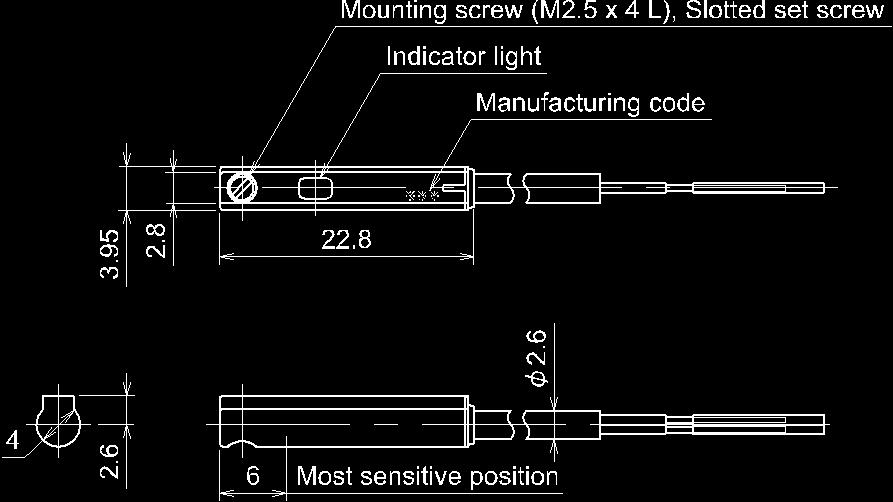
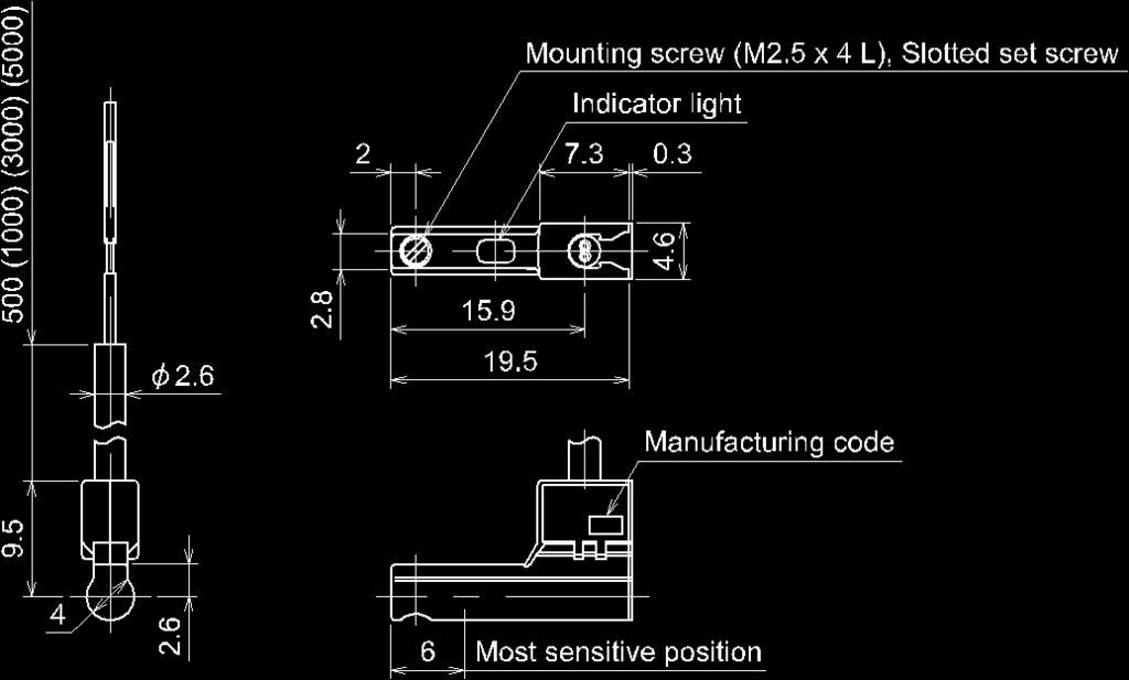
22 Dimensions D-M9B(W)/D-M9N(W)/D-M9P(W) D-M9B(W)V/D-M9N(W)V/D-M9P(W)V -21-


23 Pre-wired connector A D-M9 PC B D-M9 DPC -22-
24 Revision history A: Standardize each contents for series D-M9. B: Modify the contents. C: Limited warranty and Disclaimer are added. D: Solid state auto switch changed. D-M9 added , Sotokanda, Chiyoda-ku, Tokyo JAPAN Tel: Fax: URL Note: Specifications are subject to change without prior notice and any obligation on the part of the manufacturer SMC Corporation All Rights Reserved
Magnetic Field Resistant 2-color Indication Type Solid State Auto Switch
 PRODUCT NAME Magnetic Field Resistant 2-color Indication Type Solid State Auto Switch MODEL / Series / Product Number D-P3DW(A) * Series Contents Safety Instructions 2 Model Indication Method 8 Names and
Low Torque Metal Seal Type Rotary Joint. MQR Series
 Doc. No MQR****-OML0002-A. PRODUCT NAME Low Torque Metal Seal Type Rotary Joint MODEL / Series / Product Number MQR Series Contents 1. Contents P1 2. Model / Specifications P2~5 3. Safety Instructions
Solid State Auto Switch D-M9#A#
 PRODUCT NAME Solid State Auto Switch MODEL / Series / Product Number D-M9#A# Contents Safety Instructions 2 Model Indication and How to Order 8 Summary of Product parts 10 Summary of Product parts 10 Definition
No.EX -OME0016-A PRODUCT NAME. SI unit. MODEL / Series / Product Number EX140-SDN1
 No.EX -OME0016-A PRODUCT NAME SI unit MODEL / Series / Product Number EX140-SDN1 Table of Contents 1. Safety instructions 2 2. Specifications 7 2-1. General specifications 7 2-2. Electrical ant network
Trimmer Auto Switch D-F7K/D-Y7K D-RNK/D-RPK
 PRODUCT NAME Trimmer Auto Switch MODEL / Series / Product Number D-F7K/D-Y7K D-RNK/D-RPK Table of Contents Safety Instructions 2 Model Indication and How to Order 9 Summary of Product parts 10 Definition
0.1 mm. Actuator Position Sensor. D-MP Series. Actuator stroke position is output with an analog signal. Repeatability IP67.
 Actuator Position Sensor Actuator stroke position is output with an analog signal. IP67 Repeatability 0.1 mm (Varies depending on the operating conditions.) Analog output 4 measurement ment ranges Voltage
Trimmer Auto Switch D-M9K/D-F7K/D-Y7K D-RNK/D-RPK
 PRODUCT NAME Trimmer Auto Switch MODEL / Series / Product Number D-M9K/D-F7K/D-Y7K D-RNK/D-RPK Table of Contents Safety Instructions 2 Model Indication and How to Order 9 Summary of Product parts 10 Definition
SI unit for AS-Interface EX250-SAS#
 PRODUCT NAME SI unitfor AS-Interface MODEL / Series / Product Number EX250-SAS# Table of Contents Safety Instructions 2 Product Outline 8 Model Indication and How to Order 9 Summary of Product elements
High Vacuum Solenoid Valve PRODUCT NAME. XSA Series MODEL/ Series
 Doc. No. High Vacuum Solenoid Valve PRODUCT NAME XSA Series MODEL/ Series Thank you for purchasing this SMC product. Be sure to read this Operation Manual carefully and understand its contents before operating
Digital Flow Switch (Remote type sensor unit)
") PRODUCT NAME Digital Flow Switch (Remote type sensor unit) MODEL / Series / Product Number PFM5## Table of Contents Safety Instructions 2 Model Indication and How to Order 10 Summary of Product parts 13
PRODUCT NAME Digital Flow Switch (Remote type sensor unit) MODEL / Series / Product Number PFM5## Table of Contents Safety Instructions 2 Model Indication and How to Order 10 Summary of Product parts 13
Digital Flow Switch (Remote type monitor unit)
") PRODUCT NAME Digital Flow Switch (Remote type monitor unit) MODEL / Series / Product Number PF2A3## PF2W3## PF2D3## Table of Contents Safety Instructions 2 Model Indication and How to Order 9 Summary of
PRODUCT NAME Digital Flow Switch (Remote type monitor unit) MODEL / Series / Product Number PF2A3## PF2W3## PF2D3## Table of Contents Safety Instructions 2 Model Indication and How to Order 9 Summary of
Pressure Sensor for General Fluids PSE570/573/574
 PRODUCT NAME Pressure Sensor for General Fluids MODEL / Series / Product Number PSE570/573/574 Table of Contents Safety Instructions 2 Model Identification and How to Order 8 Names of Parts of Product
69% 30.5 mm 16 mm. Compact Guide Cylinder. Compact. lighter 0.32 kga0.1 kg (Compared with the current MGP-Z series, ø16, 10 mm stroke) Weight
 Weight") Compact Guide Cylinder ø12, ø16, ø20, ø25, ø32, ø40, ø50, ø63, ø80, ø100 RoHS Compact Overall length shortened New s ø80, ø100 added. Port thread types NPT, G added. Height shortened JMGP ø32 25 mm stroke
Compact Guide Cylinder ø12, ø16, ø20, ø25, ø32, ø40, ø50, ø63, ø80, ø100 RoHS Compact Overall length shortened New s ø80, ø100 added. Port thread types NPT, G added. Height shortened JMGP ø32 25 mm stroke
Pressure Relief 3 Port Valve With Locking Holes
 Doc. No. VH*-OMQ0023-B PRODUCT NAME Pressure Relief 3 Port Valve With Locking Holes MODEL / Series / Product Number VHS20-(F,N)01~02A,B(-B,S)(-K,R,Z) VHS30-(F,N)02~03A,B(-B,S)(-K,R,Z) VHS40-(F,N)02~04A,B(-B,S)(-K,R,Z)
1.8 w Port Solenoid Valve Direct Operated Poppet Type. New. Series VT307 CAT.ES11-107A. Power consumption
 Port Solenoid Valve Direct Operated Poppet Type Power consumption Vacuum applications New [Option] RoHS 4 Standard wtype (Existing product: 4.8 W) 0. kpa Energy-saving type.8 w (Existing product: W) A
49.5 mm Overall. 30 mm MXZ ø20. Compact. Compact Cylinder with Linear Guide. MXZ Series CAT.ES20-236A. ø12, ø16, ø20, ø25. MXZ ø20, 10 mm stroke.
 Compact Cylinder with Linear Guide ø12, ø16, ø20, ø25 RoHS Compact 49.5 mm Overall length MXZ ø20, 10 mm stroke 30 mm MXZ ø20 Width Design and assembly time is reduced due to integration of a linear guide
This filter enables direct exhaust of air in a clean room! (Cleanliness class 4*: ISO ) (* Based on SMC s measuring conditions.
 (* Based on SMC s measuring conditions.") Clean Exhaust Filter This filter enables direct exhaust of air in a clean room! (Cleanliness class 4*: ISO14644-1) (* Based on SMC s measuring conditions.) Air can be directly exhausted in a clean room
Clean Exhaust Filter This filter enables direct exhaust of air in a clean room! (Cleanliness class 4*: ISO14644-1) (* Based on SMC s measuring conditions.) Air can be directly exhausted in a clean room
High Vacuum Solenoid Valve PRODUCT NAME. XSA Series MODEL/ Series
 Doc. No. High Vacuum Solenoid Valve PRODUCT NAME XSA Series MODEL/ Series Thank you for purchasing this SMC product. Be sure to read this Operation Manual carefully and understand its contents before operating
Trimmer Auto Switch Series D- 7K/D-R K
 CAT.ES0-180 B Trimmer Auto Switch Series D- K/D-R K Large work piece OUT1 and OUT are adjustable separately. OUT1 Trimmer OUT Trimmer OUT Medium work piece Small work piece Operating range of sensor (LED
AS Series. 4.0 g. Weight: Approx. 27% lighter. Flow Rate Reproducibility. Larger Knob. Easy Identification of Product Type. 5.5 g.
 Speed Controller with One-touch Fittings In-line In-line Type y Easo t use RoHS Brass Stainless steel Reduces flow setting time! Push-lock type Knob O.D.: Almost doubled! Easy to lock ø9.4 Unlock ø5 Lock
SI unit for Ethernet POWERLINK
 PRODUCT NAME SI unit for Ethernet POWERLINK MODEL / Series / Product Number EX260 Series Table of Contents Safety Instructions 2 Model Indication and How to Order 8 Summary of Product elements 9 Installation
SI unit for EtherCAT. EX260 Series
 PRODUCT NAME SI unit for EtherCAT MODEL / Series / Product Number EX260 Series Contents Safety Instructions 2 How to Order 7 Summary of Product elements 8 Installation and Cabling 9 Installation 9 Connecting
Doc. no.vn-omm0001-c. Coolant valve PRODUCT NAME. VNC/VNH Series MODEL / Series / Product Number
 Doc. no. Coolant valve PRODUCT NAME VNC/VNH Series MODEL / Series / Product Number Contents Safety Instructions ---------------------------------------------------------------------------------- 2,3 Precautions
Digital Flow Switch (Integrated display type)
") PRODUCT NAME Digital Flow Switch (Integrated display type) MODEL / Series / Product Number PF2A7## Table of Contents Safety Instructions 2 Model Indication and How to Order 10 Summary of Product parts
PRODUCT NAME Digital Flow Switch (Integrated display type) MODEL / Series / Product Number PF2A7## Table of Contents Safety Instructions 2 Model Indication and How to Order 10 Summary of Product parts
Mini Free Mount Cylinder
 Mini Free Mount Cylinder ø, ø, ø, ø, ø, ø1, ø Series CUJ Added ø, ø1, ø bore sizes. Action Double acting Double acting Double acting Double acting Double acting Stroke 1 2 30 3 0 0 Clean series : New additions
Digital pressure switch for energy-saving control ejector
 PRODUCT NAME Digital pressure switch for energy-saving control ejector MODEL / Series / Product Number ZK2-ZSV####-A Table of Contents Safety Instructions 2 Model indication and How to order 9 Summary
Digital Flow Switch (Integrated display type)
") PRODUCT NAME Digital Flow Switch (Integrated display type) MODEL / Series / Product Number PF2A7##H Table of Contents Safety Instructions 2 Model Indication and How to Order 10 Summary of Product parts
PRODUCT NAME Digital Flow Switch (Integrated display type) MODEL / Series / Product Number PF2A7##H Table of Contents Safety Instructions 2 Model Indication and How to Order 10 Summary of Product parts
Digital Flow Switch PFM7##
 PRODUCT NAME Digital Flow Switch MODEL / Series / Product Number PFM7## Table of Contents Safety Instructions 2 Model Indication and How to Order 10 Summary of Product parts 13 Definition and terminology
Doc. no.vn -OMA0002-D. Process valve PRODUCT NAME. VNA Series MODEL / Series / Product Number
 Doc. no. Process valve PRODUCT NAME VNA Series MODEL / Series / Product Number Contents Safety Instructions ---------------------------------------------------------------------------------- 2,3 Design
Digital Gap Checker. ISA3 series
 PRODUCT NAME Digital Gap Checker MODEL / Series / Product Number ISA3 series Table of Contents 1 Before Use Safety Instructions 2 2 About this product Features 7 Model Indication and How to Order 8 Summary
Air Catch Sensor ISA2
 No.PS##-OMF0007-C PRODUCT NAME Air Catch Sensor MODEL / Series / Product Number ISA2 Table of Contents Safety Instructions 2 Model Indication and How to Order 11 Summary of Product parts 13 Definition
Technical information for LFU20-Z07-3A-X2
 Technical information for LFU20-Z07-3A-X2 Ultrasonic flow sensor and flow controller Applications: closed-loop flow control. Also requires fluid regulator (separate part) Ultrasonic flow sensor IN18796_LFU
Coolant valve. SGC/SGH Series
 Doc. no. PRODUCT NAME Coolant valve MODEL / Series / Product Number SGC/SGH Series Contents Safety Instructions ------------------------------------------------------------------------------------- 2,3
Mini Free Mount Cylinder
 Mini Free Mount Cylinder ø, ø, ø, ø, ø, ø1, ø Series CUJ Added ø, ø1, ø bore sizes. Action Double acting Single acting, spring return Double acting Single acting, spring return Double acting Single acting,
EX##-OMN0011-A. SI unit for EtherCAT PRODUCT NAME. EX260 Series MODEL/ Series
 EX##-OMN0011-A SI unit for EtherCAT PRODUCT NAME EX260 Series MODEL/ Series Contents Safety Instructions 2 How to Order 7 Summary of Product elements 8 Installation and Cabling 9 General instructions on
Digital Pressure Switch
 PRODUCT NAME Digital Pressure Switch MODEL / Series / Product Number ZSE10(F) ISE10 Table of Contents Safety Instructions 2 Model Indication and How to order 9 Summary of Product parts 11 Definition and
Doc. no.cm2*-om0064p. PRODUCT NAME Air cylinder. MODEL / Series / Product Number
 Doc. no.cm2*-om0064p PRODUCT NAME Air cylinder MODEL / Series / Product Number C*M2**-*Z C*M2**-*Z-XC85 C*M2**-*Z-X446 Contents Safety Instructions P2 1. Specifications P4 1-1. Specifications 2. Installation
Digital Gap Checker. ISA3 series
 PRODUCT NAME Digital Gap Checker MODEL / Series / Product Number ISA3 series Table of Contents 1 Before Use Safety Instructions 2 2 About this product Features 7 Model Indication and How to Order 8 Summary
Operation Manual. Model name. MRHQ Rotary Gripper. Part number / Series MRHQ10,16,20,25
 Doc. no. MRHQ-OM00002-C Operation Manual Model name MRHQ Rotary Gripper Part number / Series MRHQ10,16,20,25 - Install and operate the product only after reading the Operation Manual carefully and understanding
Dual-Rod Cylinder Compact Type
 CAT.ES-7 B Dual-Rod Cylinder Compact Type New Made to Order additionally released. (For details, refer to page 22.) Auto switch can be installed from 3 directions. Reverse Series CXSJ /ø, ø0, ø, ø, ø2,
Doc. no.ck1*-om0066p. PRODUCT NAME Clamp Cylinder. MODEL / Series / Product Number
 Doc. no.ck1*-om0066p PRODUCT NAME Clamp Cylinder MODEL / Series / Product Number CK1*40&63-**Z CKG1*40&63-**Z-** CKP1*40&63-**Z-** Contents Safety Instructions P2 1. Specifications P4 1-1. Specifications
Low Differential Pressure Sensor ±1% F.S.
 CAT.ES100-49 A Low Differential Pressure Sensor Rated differential pressure range: 0 to 2 kpa Accuracy: ±1% F.S. LED display to confirm energization Series PSE550 Proof pressure: 65kPa Output: 1 to 5VDC
Digital Pressure Switch
 PRODUCT NAME Digital Pressure Switch MODEL / Series / Product Number ZSE80(F) ISE80(H) Table of Contents Safety Instructions 2 Model Indication and How to order 9 Summary of Product parts 10 Definition
2-Color Display Digital Pressure Switch. Rated Pressure Metal Body Type (ISE75H) 2-color digital. Functions
 2-color digital. Functions") Series ISE70/75/75H NPN/PNP open collector 2 outputs added. Cut-to-zero display function added. For General Fluids For Air 2-Color Display (Green/Red) Selectable from four patterns ON Red Green Red Green
Series ISE70/75/75H NPN/PNP open collector 2 outputs added. Cut-to-zero display function added. For General Fluids For Air 2-Color Display (Green/Red) Selectable from four patterns ON Red Green Red Green
2-Color Display Digital Pressure Switch. NPN/PNP open collector 2 outputs added. Cut-to-zero display function added. Rated Pressure Metal Body Type
 Series ISE70/75/75H New NPN/PNP open collector 2 outputs added. Cut-to-zero display function added. For General Fluids For Air 2-Color Display (Green/Red) Selectable from four patterns ON Red Green Red
(Actual size) 2 switches 10 switches. Push Adjust to the set-value by the or button.
 2 switches 10 switches. Push Adjust to the set-value by the or button.") Digital Pressure Switch RoHS compliant Low profile 9.8 mm (Actual size) 13.5 mm 53.4 mm Vertical mounting space reduced to approx.! 1 2 Reduced in depth! 26.1 mm Can copy to up to 1 switches simultaneously.
Digital Pressure Switch RoHS compliant Low profile 9.8 mm (Actual size) 13.5 mm 53.4 mm Vertical mounting space reduced to approx.! 1 2 Reduced in depth! 26.1 mm Can copy to up to 1 switches simultaneously.
Doc. No.VT307 -OMH0001-C. 3 Port Direct Operated Solenoid Valve PRODUCT NAME. VT307 Series MODEL/ Series
 Doc. No. 3 Port Direct Operated Solenoid Valve PRODUCT NAME VT307 Series MODEL/ Series Contents Safety Instructions ------------------------------------------------------------------------------- 2,3 Precautions
Doc. No.VQ4000V-OMV0001. Solenoid Valve PRODUCT NAME. VQ4000/5000 (Pilot Valve V100) MODEL/ Series
 MODEL/ Series") Doc. No. Solenoid Valve PRODUCT NAME VQ4000/5000 (Pilot Valve V100) MODEL/ Series Contents Safety Instructions ---------------------------------------------------------------------------- 2,3 Precautions
Doc. No. Solenoid Valve PRODUCT NAME VQ4000/5000 (Pilot Valve V100) MODEL/ Series Contents Safety Instructions ---------------------------------------------------------------------------- 2,3 Precautions
58.5 mm. 54% lighter. Air Cylinder ø20, ø25, ø32, ø40. Approx. 1/3 97 mm. 63% reduction. 38% reduction. JCM Series CAT.ES20-237C.
 Air Cylinder ø20, ø25, ø32, ø40 RoS Overall length shortened Approx. 1/3 97 mm 50 mm stroke JCM ø40 Female thread 63% reduction 50 mm stroke 58.5 mm JCM ø40 Male thread 38% reduction 50 mm stroke New Shortened
Mounting style. B Basic style L Foot style. Shaft type. S Single shaft W Double shaft Not available for ø30. Size 11 - C D R A 1 B S C - A53
 Series 11-CRA1 Rack & Pinion type Rotary actuator: Size 3, 5 How to Order Clean series 11 Vacuum suction type Nil No D With auto switch Mounting style B Basic style L Foot style Shaft type S Single shaft
Wide Type Parallel Style Air Gripper
 Wide Type Parallel Style ir Gripper ø, ø6, ø2, ø25 Weight Max. % reduction 585 g 525 g ø6, Opening/Closing stroke: 3 mm RoHS Weight reduced by the change of the body shape and internal construction M Dust
 2-Colour Display Type High-Precision Digital Pressure Switch Series ZSE30/ISE30 How to Order Option 1 Without lead wire Nil Lead wire with connector (Lead wire length: 2m) L For positive pressure For vacuum/low
Lock unit MWB*32&100-UT-* MWB*32&100TN-UT-* MWB*32&100TF-UT-*
 Doc. no.mwb*-om0078q PRODUCT NAME Lock unit MODEL / Series / Product Number MWB*32&100-UT-* MWB*32&100TN-UT-* MWB*32&100TF-UT-* Contents Safety Instructions P. 3 1. Product Specifications P. 5 1-1. Lock
Compact Slide. Series MXH ø6, ø10, ø16, ø20
 Compact Slide Series ø, ø, ø, ø The use of an endless track linear guide produces a table cylinder having excellent rigidity, linearity and non-rotating accuracy. Endless track linear guide Series Variations
Doc. no.mx*-omp0038-d PRODUCT NAME AIR SLIDE TABLE. MODEL / Series / Product Number
 Doc. no.mx*-omp0038-d PRODUCT NAME AIR SLIDE TABLE MODEL / Series / Product Number MXQ6(A,B)-**Z* MXQ8(A,B,C)-**Z* MXQ12(A,B,C)-**Z* MXQ16(A,B)-**Z* MXQ20(A,B)-**Z* MXQ25(A)-**Z* Contents 1. Pr oduc t
No. MGP*-OM0047P-B PRODUCT NAME. Remodeled. MODEL / Series / Product Number. Series MGP-Z
 No. MGP*-OM0047P-B PRODUCT NAME Remodeled MODEL / Series / Product Number Series MGP-Z Contents Safety Instructions 2 Product feature 4 1. How to Order 5 2. Model 5 3. Specifications 5 4. Standard strokes
Dual-Rod Cylinder Compact Type
 CAT.EUS20-7 B -UK Dual-Rod Cylinder Compact Type New Made to Order additionally released. (For details, refer to page 22.) Auto switch can be installed from 3 directions. Reverse Series CXSJ/ø, ø0, ø,,
45% 6.5 mm. 6 mm. 4 mm. Compact Cylinder. Compact. lighter. JCQ Series CAT.ES20-239C. Weight. ø12, ø16, ø20, ø25, ø32, ø40, ø50, ø63, ø80, ø100
 Compact Cylinder ø12, ø16, ø20, ø25, ø32, ø40, ø50, ø63, ø80, ø100 RoHS Compact Both ends tapped mounting added. New s ø80, ø100 added. Port thread types NPT, G added. Overall length shortened 10 mm stroke
Doc. No.VG300 -OMH0002-B. 3 Port Solenoid Valve PRODUCT NAME. VG342 Series MODEL/ Series
 Doc. No. 3 Port Solenoid Valve PRODUCT NAME VG342 Series MODEL/ Series Contents Safety Instructions ---------------------------------------------------------------------------- 2,3 Precautions on Design
Doc. No.VQ1000V-OMM0002-B. Solenoid Valve PRODUCT NAME. VQ1000/2000 Series (PILOT VALVE : V100) MODEL/ Series
 MODEL/ Series") Doc. Solenoid Valve PRODUCT NAME VQ1000/2000 Series (PILOT VALVE : V100) MODEL/ Series Contents Safety Instructions ---------------------------------------------------------------------------- 2,3 Precautions
Doc. Solenoid Valve PRODUCT NAME VQ1000/2000 Series (PILOT VALVE : V100) MODEL/ Series Contents Safety Instructions ---------------------------------------------------------------------------- 2,3 Precautions
Electric Cylinder. LZB/LZC Series. It can be operated like an air cylinder. LZB Series. LZC Series LEF LEJ LEL LEM LEY LES LER LEH 25A- LEC
 Electric Cylinder LZB/LZC Series It can be operated like an air cylinder. LZB Series LZC Series Model LZB LZC Max. thrust Max. speed 196 N 0 mm/s Lead screw Slide screw: ø8, ø Lead: 2, 6, Stroke 25, 40,
Regulator Valve. VEX1 Series
 Doc. no. PRODUCT NAME Regulator Valve MODEL / Series / Product Number VEX1 Series Contents Safety Instructions ---------------------------------------------------------------------------------- 2,3 Precautions
Doc.No.LV50***-OMQ0004-D. Product. Electromagnetic Digital flow switch. Model/ Series/ Product No. LFE#### SMC Corporation
 Doc. Product Electromagnetic Digital flow switch Model/ Series/ Product No. LFE#### SMC Corporation Contents Safety Instructions 2 Model Indication and How to Order 11 Summary of Product Parts 13 Definitions
Doc.No.LV50***-OMQ0004-B. Product. Electromagnetic Type Digital flow switch. Model/ Series/ Product No. LFE#### SMC Corporation
 Doc. Product Electromagnetic Type Digital flow switch Model/ Series/ Product No. LFE#### SMC Corporation Contents Safety Instructions 2 Model Indication and How-to-Order 11 Summary of product parts 13
Doc.No.LV50***-OMQ0002-E. Product Name. Electromagnetic Digital Flow Switch. Model/ Series/ Product Number LFE#### SMC Corporation
 Doc. Product Name Electromagnetic Digital Flow Switch Model/ Series/ Product Number LFE#### SMC Corporation Contents Safety Instructions 2 Model Indication and How to Order 11 Summary of Product Parts
Speed Controller with Indicator
 Speed Controller with Indicator Numerical indication of handle rotation for flow rate reduces flow setting time and setting errors! Indicator window Body size Body size or larger Indicator window Number
Direct Operated 3-port solenoid valve
 Doc. No. PRODUCT NAME Direct Operated 3-port solenoid valve MODEL/ Series Series: VT315 Contents Safety Instructions --------------------------------------------------------------------------- 2,3 Precautions
Precision Cylinder. MTS Series. ø8, ø12, ø16, ø20, ø25, ø32, ø40 MXH MXS MXQ MXQ MXF MXW MXJ MXP MXY MTS D- -X. Series Variations MTS8
 Precision Cylinder Series, ø, ø6, ø, ø, ø, ø MXS Series Variations Model 8 Standard stroke (mm) 7 7 Rod end configuration Cushion Rubber bumper End lock Made to Order Rod Variable stroke/ through-hole
240% 19% reduced. Compact Slide. MXH Series. Improved by up to. With new high rigidity linear guide. 369g. ø6, ø10, ø16, ø g.
 Compact Slide Series ø, ø, ø, ø RoHS Allowable moment MXS Improved by up to MXQ MXQ 2% MXF MXW MXJ MXP MXY With new high rigidity linear guide MTS Allowable moment improvement illustrated below Allowable
HEAVY DUTY STOPPER CYLINDER
 Doc. no. RS2H-OM0012P- B PRODUCT NAME HEAVY DUTY STOPPER CYLINDER MODEL / Series / Product Number RS2H Series (φ50 to φ80) Contents Safety Instructions P.2 1. Specifications P.4 1-1. Cylinder specifications
High Vacuum L Type Valve
 Doc. no. PRODUCT NAME High Vacuum L Type Valve MODEL / Series / Product Number XLFV-2 Series Contents Safety Instructions - - - - - - - - - - - - - - - - - - - - - - - - - - - - 2 1. Product Specific Precautions
ISE7 /7 G Series CAT.ES B. MPa/1.6 MPa 1.0. MPa/2.0 MPa. MPa/10 MPa
 3-Screen Display High-Precision Digital Pressure Switch Air General Fluids 1.0 ISE70 ISE71 MPa/1.6 MPa 1.0 ISE70G ISE75G MPa/2.0 MPa 5.0 ISE76G ISE77G MPa/10 MPa It is possible to change the settings while
l/min (Comparison under Nozzle diameter: ø0.3, Vacuum pressure: 60 kpa) New
 New") Flow Sensor Suction check of very small workpieces This flow sensor enables precise suction. Pressure sensor Flow sensor 60 58 kpa Before suction During suction Before suction Pressure difference Small
Flow Sensor Suction check of very small workpieces This flow sensor enables precise suction. Pressure sensor Flow sensor 60 58 kpa Before suction During suction Before suction Pressure difference Small
RJ M8 size absorption time. Energy (J) RJ-L type. With cap. Short stroke type
 RJ-L type. With cap. Short stroke type") Shock Absorber Soft type Stops transported objects softly % reduced absorption time Unique mechanism to achieve a variable sectional area of the fluid channel proportional to the stroke (compared with
Shock Absorber Soft type Stops transported objects softly % reduced absorption time Unique mechanism to achieve a variable sectional area of the fluid channel proportional to the stroke (compared with
SeriesMHZL2 How to Order
 Parallel Type ir Gripper Long Stroke SeriesMHZL2 How to Order 1 2 2 ore size Number of fingers 2 2 fingers 1mm mm 2mm 2mm MHZL2 D S C ction Double acting Single acting (normally open) Single acting (normally
Cat. No. I526-E1-1 USER S MANUAL 3G3IV-PLKEB2 /4. Braking Resistor Units 3G3IV-PCDBR2 B/4 B. Braking Units
 Cat. No. I526-E1-1 USER S MANUAL 3G3IV-PLKEB2 /4 Braking Resistor Units 3G3IV-PCDBR2 B/4 B Braking Units Thank you for choosing an OMRON Braking Resistor Unit and Braking Unit. Proper use and handling
High Vacuum Solenoid Valve. 25% reduction. Max. Weight. 18% * lighter. Max. * XSA2-2 AC 100 V, 200 V, 110 V, 220 V, 240 V, 48 V, 24 V, 230 V DC
 Normal lose High Vacuum Solenoid Valve Minimum operating pressure * 1x10 6 Pa(abs) * OUT side Leakage Internal 1.3 x10 9 Pa m3/s Note) Note) Except grommet/ RoHS External 1.3 x10 11 Pa m3/s 2 types of
Electro-pneumatic proportional valve
 Doc. no. PRODUCT NAME Electro-pneumatic proportional valve MODEL / Series / Product Number VEP/VEF/VEA/VER Series Contents Safety Instructions ----------------------------------------------------------------------------------
Free Mount Cylinder. Series. Series CU CAT.EUS20-95 B -UK. Space-saving. Auto Switch Capable P. 4, 23, 37 P. 45 P. 43
 CAT.EUS- B -UK Free Mount Cylinder A space-saving air cylinder with multiple surfaces capable of direct mounting. Offered in many variations. Space-saving The multiple surface direct mounted rectangular
Series MHS. 2, 3, 4 Finger Air Gripper D-F9P. Auto Switch Common Specifications. Auto Switch Common Specifications. Lead Wire Color Changes
 2,, Finger Air Gripper Auto Switch Common Specifications Auto Switch Common Specifications Operating time Impact resistance Insulation resistance Withstand voltage Ambient temperature Enclosure Solid state
Guide Table. MGF Series
 Guide Table MGF Series ø, ø, ø0 Low-profile compact cylinder utilizes a large concentric guiding sleeve to provide excellent eccentric load resistance. Mounting height greatly reduced Low-profile cylinder
2-Color Display High-Precision Digital Pressure Switch Series ZSE40A(F)/ISE40A
/ISE40A") 2-Color Display High-Precision Digital Pressure Switch Series ZSEA(F)/ISEA New M8 connector type RoHS IP65 Applicable fluid Air, Non-corrosive gas, Non-flammable gas Can copy to up to 10 switches simultaneously.
2-Color Display High-Precision Digital Pressure Switch Series ZSEA(F)/ISEA New M8 connector type RoHS IP65 Applicable fluid Air, Non-corrosive gas, Non-flammable gas Can copy to up to 10 switches simultaneously.
Technical Specifications
 No.:EX##-OMG0007 Technical Specifications Product name : SI unit Model : EX250-SAS7 EX250-SAS9 Contents 1. Safety 2. Specifications 2-1 General specification 2-2 Communication specification 2-3 Electrical
SG-B1 SERIES / SG-A1 SERIES
 643 Door with Solenoid Interlock / Door Ultra-slim SG-B1 SERIES / SG-A1 SERIES Related Information General terms and conditions... F-7 General precautions... P.1501 PHOTO PHOTO Conforming to Machine &
Series MXH. Compact Slide. ø6, ø10, ø16, ø20
 CAT.EUS-12 B -UK Compact Slide Series MXH ø, ø, ø1, ø The use of an endless track linear guide produces a table cylinder having excellent rigidity, linearity and non-rotating accuracy. Made to Order -XB13:
Features. 2-wire type available. Max. operation distance: 1.5 mm 0.06 in (Stable sensing range 0 to 1.2 mm 0.05 in)
") 817 Cylindrical Inductive Proximity Sensor SERIES Related Information General terms and conditions... F-3 Glossary of terms...p.1576~ guide... P.781~ General precautions... P.1579~ PHOTO PHOTO panasonic.net/id/pidsx/global
817 Cylindrical Inductive Proximity Sensor SERIES Related Information General terms and conditions... F-3 Glossary of terms...p.1576~ guide... P.781~ General precautions... P.1579~ PHOTO PHOTO panasonic.net/id/pidsx/global
How to Order M9BW. Action. Double acting Single acting. Load voltage Electrical entry direction M9NWV M9NW 12 V 5 V, M9BWV M9BW 12 V 12 V
 Angular Type Air Gripper/Standard Type 2 Series ø, ø1, ø20, ø25 How to Order Angular type air gripper 2 20 Bore size mm 1 1 mm 20 20 mm 25 25 mm D S Action D Double acting Single acting M9BW Made to Order
2-Color Display High-Precision Digital Pressure Switch
 2-Color Display High-Precision Digital Pressure Switch Series ZSE3/ISE3 2-color digital display allows you to choose the setting according to your application requirements. 4 different display settings
TECHNICAL GUIDE FOR PROXIMITY SENSORS DEFINITIONS YAMATAKE PROXIMITY SENSOR CATEGORIES
 TECHNICAL GUIDE FOR PROXIMITY SENSORS DEFINITIONS "" includes all sensors that detect the presence of a metallic object approaching the sensing face or near the sensing face without mechanical contact.
Guide Table. ø40, ø63, ø100
 Guide Table Series MGF ø, ø, ø Low-profile compact cylinder utilizes a large concentric guiding sleeve to provide excellent eccentric load resistance. Mounting height greatly reduced Low-profile cylinder
Model Number Structure
 Conductive Level Controller CSM DS_E_1_1 Ideal for level control for industrial facilities and equipment. Outputs can be set to self-hold at or using self-holding circuits. Sensitivity adjustment of operating
Low Profile Air Gripper. Series MHF2. Low profile air gripper with space-saving design is newly released. 5-77
 Low Profile Air Gripper Low profile air gripper with space-saving design is newly released. 5-77 Low Profile Air Gripper Height is approximately / the size of an equivalent Series MHZ2. MHZ2-D 42 Bore
3 Port 3 Position Valve
 Port Position Valve Pilot Solenoid ir Operated ohs Intermediate stopping of cylinders * up to ø15 is possible. Pilot solenoid Manifold ir operated * For VEX 4, 00 mm/s, horizontal movement Power consumption:
Inductive Proximity Sensor
 Inductive Proximity Sensor General-purpose Type in a Basic Switch Housing Mounting pitch compatible with that of mechanical basic switch. Wide operating voltage range: 10 to 30 VDC or 90 to 250 VAC. LED
Lumitester PD-20 Control Kit
 日本語による取扱説明は 17 ページからとなります Lumitester PD-20 Control Kit Operation manual Thank you for purchasing the Lumitester PD-20 Control Kit. To use this kit safely and correctly, read this operation manual carefully
Free Mount Cylinder. Series CU. A space-saving air cylinder with multiple surfaces capable of mounting directly. Offered in rich variations.
 Free Mount Cylinder Series CU A space-saving air cylinder with multiple surfaces capable of mounting directly. Offered in rich variations. Space-saving The multiple surface direct mounting with a square
Cylindrical Inductive Proximity Sensor GX-M SERIES
 Cylindrical Inductive Proximity Sensor GX-M SERIES Listing (2 m cable length type only) Features Wide product range Types: DC 3-wire shielded type DC 3-wire non-shielded type DC 2-wire standard type DC
Operation Manual. Document No.: KE KITZ EKSR Series Spring Return Type Electric Actuators. For KITZ Ball Valves
 Document No.: KE-4041-00 Operation Manual KITZ EKSR Series Spring Return Type Electric Actuators For KITZ Ball Valves Thank you for choosing KITZ products. For safe and trouble-free function and performance
Read and understand this manual for safely usage.
 TS02-0183 INSTRUCTION MANUAL FOR GUARD TYPE LEVEL SENSOR MODEL:FC Read and understand this manual for safely usage. This manual describes the product of standard specification. Read the other manual for
Parallel Style Air Gripper: Wide Type
 Parallel Style Air Gripper: Wide Type Series MHL Built-in dust-protection mechanism A scraper with a dust lip is adopted for all rod rotating parts. A large amount of gripping force is provided through