en Light Tower LTC 4 REPAIR MANUAL
|
|
|
- Blake Payne
- 6 years ago
- Views:
Transcription
1 en Light Tower LTC 4 REPAIR MANUAL E N
2
3 LTC Repair This manual covers the following machines: Item No. Revisions and lower and lower and lower and lower and lower Foreword Operating / Parts Information You must be familiar with the operation of this machine before you attempt to troubleshoot or repair it. Basic operating and maintenance procedures are described in the Operator s Manual supplied with the machine. Keep a copy of the Operator s Manual with the machine at all times. Use the separate Parts Book supplied with the machine to order replacement parts. If you are missing either of the documents, please contact Wacker Neuson Corporation to order a replacement. Damage caused by misuse or neglect of the unit should be brought to the attention of the operator to prevent similar occurrences from happening in the future. This manual provides information and procedures to safely repair and maintain the above Wacker Neuson model(s). For your own safety and protection from injury, carefully read, understand, and observe all instructions described in this manual. THE INFORMATION CONTAINED IN THIS MANUAL IS BASED ON MACHINES MANUFACTURED UP TO THE TIME OF PUBLICATION. WACKER NEUSON CORPORATION RESERVES THE RIGHT TO CHANGE ANY PORTION OF THIS INFORMATION WITHOUT NOTICE. 3
4 Foreword LTC Repair WARNING CALIFORNIA Proposition 65 Warning: Diesel engine exhaust, some of its constituents, and certain vehicle components contain or emit chemicals known to the State of California to cause cancer and birth defects or other reproductive harm. All rights, especially copying and distribution rights, are reserved. Copyright 2008 by Wacker Neuson Corporation No part of this publication may be reproduced in any form or by any means, electronic or mechanical, including photocopying, without express written permission from Wacker Neuson Corporation. Any type of reproduction or distribution not authorized by Wacker Neuson Corporation represents an infringement of valid copyrights, and violators will be prosecuted. We expressly reserve the right to make technical modifications, even without due notice, which aim at improving our machines or their safety standards. 4
5 LTC Repair Table of Contents 1. Safety Information Laws Pertaining to Spark Arresters Operating Safety Operator Safety while using Internal Combustion Engines Towing Safety Service Safety Label Locations Safety and Operating Labels Technical Data Engine Generator Machine Operation Information Regarding Operation Locating Trailer Leveling Trailer Adjusting Lights Preparing Trailer for Towing or Lifting Raising Tower (Manual Winch System) Lowering Tower (Manual Winch System) Raising Tower (Power Winch System) Lowering Tower (Power Winch System) Emergency Crank Handle (Power Winch System) Control Panels Lombardini (Manual Winch System) Control Panels Lombardini (Power Winch System) Control Panels CAT (Manual Winch System) Control Panel CAT (Power Winch System) Starting Lombardini Starting CAT Automatic Shutdown Operating Lights Stopping Lombardini Stopping CAT Derating Receptacles 60 Hz wc_br en_004toc.fm 5
6 Table of Contents LTC Repair 4. Maintenance Periodic Maintenance Schedule Lombardini Periodic Maintenance Schedule CAT Daily Inspection Installing / Removing Light Fixtures Precautions When Replacing / Removing Bulbs Replacing Bulbs Air Cleaner Engine Oil Generator Capacitor Excitation Schematic 60 Hz Schematic for 60 Hz Metal Halide 4-Light Units Metal Halide Schematic Components Engine Wiring Lombardini Engine Wiring Components Lombardini Engine Control Panel Internal Wiring Lombardini Engine Wiring Lombardini Engine Control Panel Internal Wiring Lombardini Engine Control Panel Components Lombardini Engine Wiring Item Number: Engine Wiring Item Number: , Power Winch Schematic Trailer Wiring Lombardini Engine Troubleshooting Troubleshooting Flowcharts Engine Does Not Crank Flowchart 3A Checking Keyswitch and Wiring Replacing Keyswitch Engine Cranks But Does Not Start Flowchart 4A Checking Fuel System Checking Voltage to Glow Plugs (Lombardini 903 engines) Checking Voltage to Glow Plugs (Lombardini 1003 engines) Checking Glow Plug Relay Replacing Glow Plug Relay Checking Glow Plugs Engine Shuts Down Flowchart 5A Checking Oil Pressure and Coolant Temperature Switches General Engine Troubleshooting...79 wc_br en_004toc.fm 6
7 LTC Repair Table of Contents 6. Caterpillar Engine Troubleshooting Troubleshooting Flowcharts Engine Does Not Crank Flowchart 6A Checking Keyswitch and Wiring Replacing Keyswitch Engine Cranks But Does Not Start Flowchart 7A Checking Fuel Flow Checking Glow Plug Wiring Checking Glow Plugs Engine Shuts Down Flowchart 8A Checking Oil Pressure and Coolant Temperature Switches General Engine Troubleshooting Electrical Troubleshooting Procedures Troubleshooting Methodology Schematic Components Schematic for 60 Hz Metal Halide 4-Light Units Checking Continuity Checking resistance Checking voltage Troubleshooting Flowcharts Lights do not Illuminate Flowchart 1A Lights do not Illuminate Flowchart 1B Lights do not Illuminate Flowchart 1C Lights do not Illuminate Flowchart 1D Checking Engine Speed Checking Generator Voltage at Receptacle Replacing Receptacle Checking Voltage to the Main Circuit Breaker Checking Voltage Between Main Circuit Breaker and Terminal Strip Checking Individual Circuit Breakers Confirming a Malfunctioning Circuit Breaker Checking Incoming Voltage to Control Panel Capacitor(s) Checking Outgoing Voltage from Control Panel Capacitor(s) Confirming a Faulty Control Panel Capacitor Checking Wiring to/from Ballast(s) Replacing Ballast Restoring Rotor Magnetism (Flashing) / Checking Rotor Winding Checking Generator Capacitors wc_br en_004toc.fm 7
8 Table of Contents LTC Repair 7.26 Alternative Capacitor Check Replacing Generator Capacitor(s) Checking Stator Windings Removing/Installing Caterpillar Engine with Generator Removing/Installing Lombardini Engine with Generator Separating Stator Assembly from Engine/Rotor Assembly Remounting Stator Assembly to Rotor/Engine Assembly Checking Rotor Diodes Checking Rotor Windings Removing/Installing Rotor No Voltage at Receptacle Flowchart 2A Checking Voltage at Receptacle Checking Receptacle s Circuit Breaker Troubleshooting the Power Winch Disassembly/Assembly Procedures Tools Ordering Parts Reference Numbers ( ) Weight Block Light Assembly Tower Assembly Exploded View Tower Assembly List of Parts Upper Mast Mid Mast Main Mast Replacing Cable and Winch on Power Winch Models Replacing Fuel Tank Replacing Hour Meter wc_br en_004toc.fm 8
9 LTC Repair 1. Safety Information Safety Information This manual contains DANGER, WARNING, CAUTION, NOTICE and NOTE callouts which must be followed to reduce the possibility of personal injury, damage to the equipment, or improper service. This is the safety alert symbol. It is used to alert you to potential personal injury hazards. Obey all safety messages that follow this symbol to avoid possible injury or death. DANGER indicates a hazardous situation which, if not avoided, will result in death or serious injury. DANGER WARNING indicates a hazardous situation which, if not avoided, could result in death or serious injury. WARNING CAUTION indicates a hazardous situation which, if not avoided, could result in minor or moderate injury. CAUTION NOTICE: Used without the safety alert symbol, NOTICE indicates a situation which, if not avoided, could result in property damage. Note: Contains additional information important to a procedure. 1.1 Laws Pertaining to Spark Arresters Notice: State Health Safety Codes and Public Resources Codes specify that in certain locations spark arresters be used on internal combustion engines that use hydrocarbon fuels. A spark arrester is a device designed to prevent accidental discharge of sparks or flames from the engine exhaust. Spark arresters are qualified and rated by the United States Forest Service for this purpose. In order to comply with local laws regarding spark arresters, consult the engine distributor or the local Health and Safety Administrator. wc_si000164gb.fm 9
10 Safety Information 1.2 Operating Safety LTC Repair Familiarity and proper training are required for the safe operation of the machine. Machines operated improperly or by untrained personnel can be hazardous. Read the operating instructions contained in both this manual and the engine manual and familiarize yourself with the location and proper use of all controls. Inexperienced operators should receive instruction from someone familiar with the machine before being allowed to operate it The area immediately surrounding the Light Tower should be clean, neat, and free of debris Be sure the machine is on a firm, level surface and will not tip, roll, slide, or fall while operating NEVER start a machine in need of repair Lower the tower when not in use, or if high winds or electrical storms are expected in the area ALWAYS make certain the machine is well-grounded and securely fastened to a good earthen ground per national and local regulations The tower extends up to 9 m (30 ft.). Make sure the area above the trailer is open and clear of overhead wires and obstructions The lamps become extremely hot in use! Allow the lamp and fixture to cool minutes before handling Keep the area behind the trailer clear of people while raising and lowering the mast! Never raise, lower or turn the mast while unit is operating! The trailer must be leveled and the outriggers extended before raising the tower. The outriggers must remain extended while the tower is up If for any reason any part of the mast hangs up or the winch cable develops slack while raising or lowering the tower, STOP immediately! Contact an authorized WACKER service representative NEVER remove the mast locking pin while the tower is up! NEVER use the machine if the insulation on the electrical cord is cut or worn through NEVER operate the lights without the protective lens cover in place or with a lens cover that is cracked or damaged! NEVER adjust the mast while the unit is operating NEVER raise the mast or operate the machine in high winds. wc_si000164gb.fm 10
11 LTC Repair Safety Information 1.3 Operator Safety while using Internal Combustion Engines Internal combustion engines present special hazards during operation and fueling. Read and follow the warning instructions in the engine owner s manual and the safety guidelines below. Failure to follow the warnings and safety standards could result in severe injury or death NEVER operate the machine indoors unless exhaust fumes can be adequately ventilated Do not fill or drain the fuel tank near an open flame, while smoking, or while the engine is running Refill the fuel tank in a well-ventilated area Do not touch or lean against hot exhaust pipes Replace the fuel tank cap after refueling Do not remove the radiator cap when the engine is running or hot. The radiator fluid is hot and under pressure and may cause severe burns! Do not use gasoline or other types of fuels or flammable solvents to clean parts, especially in enclosed areas. Fumes from fuels and solvents can become explosive Keep the area around the muffler free of debris such as leaves, paper, cartons, etc. A hot muffler could ignite the debris and start a fire. WARNING wc_si000164gb.fm 11
12 Safety Information 1.4 Towing Safety LTC Repair WARNING Towing a large trailer requires special care. Both the trailer and vehicle must be in good condition and securely fastened to each other to reduce the possibility of an accident ALWAYS check that the hitch and coupling on the vehicle are rated equal to, or greater than, the trailer's gross vehicle weight rating (GVWR) ALWAYS inspect the hitch and coupling for wear or damage. DO NOT tow the trailer using defective parts ALWAYS make sure the coupling is securely fastened to the vehicle ALWAYS check the tires on the trailer for tread wear, inflation, and condition. Replace worn tires ALWAYS connect the safety chains ALWAYS make sure directional and trailer lights are connected and working properly ALWAYS check that the lug nuts holding the wheels are tight and that none are missing The maximum recommended speed for highway towing is 72 km/hour (45 MPH). Recommended off-road towing speed is not to exceed 16 km/hour (10 MPH) or less depending on terrain ALWAYS refer to the applicable Department of Transportation regulations before towing. wc_si000164gb.fm 12
13 LTC Repair 1.5 Service Safety Safety Information WARNING HIGH VOLTAGE! This unit uses high voltage circuits capable of causing serious injury or death. Only a qualified electrician should troubleshoot or repair electrical problems occurring with this equipment ALWAYS replace the safety devices and guards after repairs and maintenance Before servicing the Light Tower, make sure the engine start switch is turned to the OFF position, the circuit breakers are open (off), and the negative terminal on battery is disconnected. NEVER perform even routine service (oil/filter changes, cleaning, etc.) unless all electrical components are shut down DO NOT allow water to accumulate around the base of the machine. If water is present, move the machine and allow the machine to dry before servicing DO NOT service the machine if your clothing or skin is wet ALWAYS keep hands, feet, and loose clothing away from the moving parts on the generator and engine Keep the machine clean and labels legible. Replace all missing and hard-to-read labels. Labels provide important operating instructions and warn of dangers and hazards ALWAYS make sure slings, chains, hooks, ramps, jacks and other types of lifting devices are attached securely and have enough weightbearing capacity to lift or hold the machine safely. Always remain aware of the location of other people in the area when lifting the machine ALWAYS turn off the light circuit breakers and shut down the engine before disconnecting the light fixtures or changing the light bulbs. wc_si000164gb.fm 13
14 Safety Information 1.6 Label Locations LTC Repair wc_si000164gb.fm 14
15 LTC Repair Safety Information wc_si000164gb.fm 15


16 Safety Information 1.7 Safety and Operating Labels LTC Repair Wacker Neuson machines use international pictorial labels where needed. These labels are described below: Ref. Label Meaning A DANGER! A non-secured, falling mast will cause serious injury or death if a person is hit. To secure mast, verify automatic locking pin has engaged to secure tower upright. B WARNING! Avoid crushing area. C WARNING! Completely lower tower before tilting mast. Tilting an extended mast could cause serious injury or death. D DANGER! Contact with overhead electrical power lines will cause serious injury or death. Do not position Light Tower under electrical power lines. wc_si000164gb.fm 16


17 LTC Repair Safety Information Ref. Label Meaning E CAUTION! Lifting point. F WARNING! Secure mast in transport lock before lifting or towing. A loose swinging mast could cause personal injury or machine damage. G DANGER! Asphyxiation hazard. Read the Operator s Manual for instructions. No sparks, flames, or burning objects near machine. Stop the engine before adding fuel. Use only diesel fuel. H DANGER! Asphyxiation hazard. Read the Operator s Manual for instructions. No sparks, flames, or burning objects near machine. Stop the engine before adding fuel. Use only diesel fuel. DANGER! Contact with overhead electrical power lines will cause serious injury or death. Do not position Light Tower under electrical power lines. WARNING! Completely lower tower before tilting mast. Tilting an extended mast could cause serious injury or death. I DANGER! Electrical storage device within. Contact a qualified electrician for service or to open electrical box. Electric shock will cause serious injury or death. wc_si000164gb.fm 17
18 Safety Information LTC Repair Ref. Label Meaning J Electrical ground K WARNING! Stand clear of front and rear of machine when mast is being tilted up or down. L WARNING! Hot surface! M A nameplate listing the model number, item number, revision number, and serial number is attached to each unit. Please record the information found on this plate so it will be available should the nameplate become lost or damaged. When ordering parts or requesting service information, you will always be asked to specify the model number, item number, revision number, and serial number of the unit. N WARNING! Ultraviolet radiation from lamp can cause serious skin and eye irritation. Use only with provided undamaged lens cover and fixture. wc_si000164gb.fm 18
19 LTC Repair Safety Information Ref. O Label P / ) * , ), 2-4 ) ) 7 ) * * ) - ) 7 ), ) ) 6 -, ) ) 0 ) / / , ) ) / / ) 6 1 /, 1-, - 4 / - 5 ) 6 * * 5 / ) ) ), 2 ) 4 ) ) + ) 5 -, * 7 6! ; ) 6 6 ) ) , , ! ) 0 ) / ) 7 /. ) /! ) 5 - / , - ) ) 4 4 ) ) " ) 6 6 ) ). - 6 ; + 0 ) / * / ) , ) " ) * 4 1 / - " ) 5 + ), - ) 5, / 7 4 1, ), # ) 1-4 1/ # ) 0 ) / # ) , , ) / ) , / , ) ) / ) 7, - * 16 1 ), 7 2 1, 5 * 4 7 6, , ) ! ) 6 6 ) ) ) ) " ) 6 6 ) ) 1-5, ) , # ) 2-5, - ) " & ' " wc_si000164gb.fm 19
20 Safety Information LTC Repair Ref. Q Label wc_si000164gb.fm 20
21 LTC Repair Safety Information Ref. Label Meaning R Coolant overflow bottle only, not a return system. S WARNING! Pinching hazard. Rotating machinery. Certification Label (VIN Number) Also attached to each unit is a Certification Label. This label specifies that the trailer conforms with all Federal Motor Vehicle Standards in effect at the time of manufacture. The label includes the Vehicle Identification Number (VIN) for the trailer. wc_si000164gb.fm 21
22 Safety Information Notes LTC Repair wc_si000164gb.fm 22
23 LTC 4 2. Technical Data Technical Data 2.1 Engine Item Number: LTC 4L Rev. 102 & lower LTC 4L Rev. 103 & above LTC 4C Engine Make Lombardini Caterpillar Model LDW903 LDW Type 3-cylinder, 4-cycle, liquid-cooled diesel Maximum power rating kw (Hp) 9.0 (12.1) 10 (13.4) 9.4 (12.6) Operating power rating kw (Hp) 8.1 (10.9) 9.1 (12.2) 8.1 (10.9) Operating speed (no-load) rpm Alternator V / A / W 12 / 45 / 540 Battery V/Ah/CCA 12 / 450 Air cleaner type dry-type element Fuel type No. 2 diesel Fuel tank capacity l (gal.) 114 (30) Fuel consumption l (gal.) / hr (0.44) 1.70 (0.45) 1.70 (0.45) Running time hours Coolant capacity l (qts.) 4.7 (5.0) Oil capacity l (qts.) 2.4 (2.5) 3.5 (3.7) Oil weight SAE 15W40 CD or higher wc_td000157gb.fm 23
24 Technical Data LTC Generator Item Number: LTC 4L - 60 Hz Generator LTC 4C - 60 Hz Frequency Hz 60 ± 2 Continuous output kw 6.0 Output volts/phase 120 / 1Ø Amps A 50 / 25 Excitation type Capacitor / Brushless Power factor 1.0 Voltage regulation - No % ± 5.0 load to full load Speed (no-load) rpm 1850 wc_td000157gb.fm 24
25 LTC Machine Technical Data LTC 4L LTC 4C Item Number Machine Operating weight (GVWR) kg (lbs.) 815 (1800) 821 (1811) 817 (1802) 832 (1834) Dimensions (L x W x H) cm (in.) 389 x 122 x 160 (153 x 48 x 63) 439 x 162 x 160 (173 x 64 x 63) Height - mast extended m (ft.) 9 (30) Lighting system (1000W) Ballast Max. lighting 0.5 ft. candles m 2 (acres) x 122 x 160 (153 x 48 x 63) Coil and core 30,400 (7) 439 x 162 x 160 (173 x 64 x 63) Sound level at 7 m db(a) (23 ft.) Tires size ST175 / 80D13 wc_td000157gb.fm 25
26 Technical Data LTC 4 Notes wc_td000157gb.fm 26
27 LTC 3. Operation Operation 3.1 Information Regarding Operation 3.2 Locating Trailer The information regarding the operation of the machine included in this manual is condensed. Refer to the Operator s Manual for complete operating instructions. Always read, understand, and follow the procedures in the Operator s Manual when operating the machine. See Graphic: wc_gr For maximum light coverage locate the Light Tower at ground level or in a spot higher than the area being lighted Position the trailer on a firm, flat surface clear of overhead wires and obstructions. Be sure that there is enough area for outrigger extensions to be fully extended Connect the ground stud (l) located on the trailer frame to a good earthen ground. Consult local codes for proper grounding techniques. The tower extends up to 9 m (30 ft.). Make sure the area above the trailer is open and clear of overhead wires and obstructions. WARNING wc_tx000543gb.fm 27
28 Operation LTC 3.3 Leveling Trailer See Graphic: wc_gr001420, wc_gr The trailer must be leveled and the outriggers extended before raising the tower. The outriggers must remain extended while the tower is up. Failure to level the trailer or extend the outriggers will severely reduce WARNING the stability of the unit and could allow the tower to tip and fall Pull the locking pin on the tongue jack (a) and rotate the tongue jack 90 as shown. Make sure the tongue jack snaps into position. Block or chock the trailer wheels (b). Crank the tongue jack down to raise the trailer tongue off the vehicle Pull the outrigger lock pin (c) to release the outrigger. Pull both outrigger extensions (d) out until you feel outrigger lock pin lock back into place. Rotate jacks (e) down until they snap into position Rotate rear jack (f) down, as shown, making sure it snaps into place Extend the jack(s) on the highest side(s) of the trailer until they rest firmly on the ground. Extend the remaining jacks until the trailer is level. 3.4 Adjusting Lights See Graphic: wc_gr Each light fixture can be aimed up, down, left or right. Position each fixture by loosening toolless light adjusters (g) and aiming the light up or down. DO NOT loosen the inside nut (x). Loosening this nut could cause damage to the light fixture. Loosen the nut (h) to turn light fixtures left or right. Tighten adjusters and nuts after positioning the lights. Always return the light fixtures to aim at the ground when mast is in the cradle for towing. wc_tx000543gb.fm 28
29 LTC 3.5 Preparing Trailer for Towing or Lifting Operation See Graphic: wc_gr001423, wc_gr Check that the tower cradle lock pin (j) is in place and secured with the safety pin Ensure that the tower is completely nested inside the transport cradle and the pin (t) is secure Make sure the doors are properly latched Return the outriggers to their travel position. Check that the outrigger bars and jacks are locked in place Crank the rear jack (f) all the way in and rotate it 90. The the Light Tower is now ready to lift. For towing, continue Use the tongue jack (a) to raise the trailer tongue up and then lower it over hitch on towing vehicle. Lock the hitch to coupling and attach the safety chains. Swivel the tongue jack 90 and lock it in place Connect the trailer wiring to the towing vehicle. Check the brake, turn, and tail lights for proper operation Position the light fixtures down (k). For rough, off-road transportation remove bulbs from fixtures to avoid damage Check the tire inflation Attach a red flag to the end of tower before towing. NOTICE: Maximum recommended speed for highway towing is 72 km/hour (45 MPH). Recommended off-road towing speed is not to exceed 16 km/hour (10 MPH) or less depending on terrain. wc_tx000543gb.fm 29
30 Operation 3.6 Raising Tower (Manual Winch System) LTC See Graphic: wc_gr WARNING NEVER raise the tower or operate the Light Tower in high winds. NEVER raise the tower while the engine is running. WARNING HIGH VOLTAGE! DO NOT use the Light Tower if insulation on electrical cord is cut or worn through. Repair or replace the cord before using. Bare wires in contact with the metal frame of the trailer or tower can cause electrocution. DO NOT position the Light Tower under electrical power lines. WARNING NEVER allow anyone to stand near the rear of the unit while raising the tower. The Light Tower includes two separate winches one for lifting the tower to the vertical position, the other for raising the tower. Each winch is an automatic brake-type winch that automatically brakes when the handle is released. The handle must be rotated to wind in cable as well as unwind cable. WARNING NEVER touch the winch pawl! Releasing the pawl may cause the tower or tower to fall Check winch cables (n) for wear or damage, and make sure they are resting properly in pulleys. Do not use the Light Tower if either winch cable is damaged Remove the cradle locking pin (j) from the cradle Check the operation of the tongue-mounted winch (o) by rotating the winch handle 1/4-turn clockwise ( cable in direction). The winch pawl must engage winch gear teeth. When operating properly, the winch pawl will make a clicking sound when the winch handle is rotated clockwise. Do not attempt to raise the tower if the winch is damaged or not operating properly Continue to rotate the winch handle and raise the tower to the vertical position until the vertical tower locking pin (p) locks the tower in place. Be certain the vertical tower locking pin is fully engaged in the locking position before raising the tower. wc_tx000543gb.fm 30


31 LTC Operation NEVER pull the vertical tower locking pin (p) while the tower is raised! Releasing the vertical tower locking pin while the tower is raised may cause the tower to fall or the machine to tip over After the tower is in the vertical position, check the operation of the tower-mounted winch (q) by rotating the winch handle 1/4-turn clockwise ( cable in direction). The winch pawl must engage winch gear teeth. When operating properly, it will make a clicking sound when the winch handle is rotated clockwise. Do not attempt to raise the tower if the winch is damaged or not operating properly. Continue rotating the winch handle until tower is at the desired height. Do not over crank the winch when the tower is fully extended. NOTICE: Do not extend the tower beyond the red marking on the tower! Once the tower is at the desired height, rotate the tower to the desired direction. To rotate, loosen rotation locking knob (s). Then using the handle (u), rotate the tower until the lights face the desired direction, and then retighten the rotation locking knob. WARNING u j s q n n o p t wc_gr wc_tx000543gb.fm 31
32 Operation 3.7 Lowering Tower (Manual Winch System) LTC See Graphic: wc_gr Be sure to read and understand the operating instructions before lowering the tower! If for any reason a part of the tower hangs up or a winch cable develops slack before tower is fully lowered, stop immediately! Continuing to turn the winch handle will increase the slack in the cable. Too much slack could cause the tower to collapse should it suddenly free up. If the tower hangs up, level the trailer. Slightly shake or twist the tower assembly to free the bind. Contact an authorized WACKER service representative immediately. WARNING NEVER lower the tower while the unit is operating. WARNING WARNING NEVER allow anyone to stand near the rear of the unit while lowering the tower Turn the lights off. Shut down the engine. NOTICE: Shutting down the engine before turning off the lights could damage floodlight ballasts or generator capacitor(s). NOTICE: Observe power cord while lowering the tower. Make sure the coiled cord is not damaged during the lowering process Lower the tower by turning the handle on the tower-mounted winch (q) counterclockwise ( cable out direction). WARNING NEVER touch the winch pawl! Releasing the winch pawl may cause the tower or tower to fall Loosen the rotation locking knob (s) and using the handle (u), rotate the tower so the lights face the rear of the trailer and the towermounted winch is facing toward the trailer tongue. wc_tx000543gb.fm 32
33 LTC Operation Pull and hold the tower locking pin (p). Rotate the handle on the tongue-mounted winch (o) counterclockwise ( cable out direction) until the tower spring begins to pivot the tower down. Release the tower locking pin and continue to rotate the handle until the tower is resting in the transport cradle. Be sure that the secondary locking pin (t) penetrates all sections of the tower. WARNING NEVER pull the vertical tower locking pin (e) while the tower is raised! Releasing the locking pin while the tower is raised may cause the tower to fall or the machine to tip over After the tower is down, secure it in the cradle by inserting the cradle lock pin (j). Insert the clip through the pin to secure it in place Position the light fixtures to aim at the ground. NOTICE: Allow the floodlights to cool minutes before moving trailer. Moving the trailer while the lights are still hot could cause the bulbs to break. wc_tx000543gb.fm 33
34 Operation 3.8 Raising Tower (Power Winch System) LTC See Graphic: wc_gr002759, wc_gr ALWAYS observe the tower while raising and lowering the mast. NEVER raise the mast or operate the Light Tower in high winds. WARNING NEVER raise the mast while the engine is running. WARNING HIGH VOLTAGE! DO NOT use Light Tower if insulation on electrical cord is cut or worn through. Repair or replace cord before using. Bare wires in contact with the metal frame of the trailer or the Light Tower can cause electrocution. DO NOT position the Light Tower under electrical power lines. WARNING NEVER allow anyone to stand near the rear of the unit while raising the mast. The Light Tower includes two separate winches. One for lifting the mast to the vertical position, the other for raising the tower Check the winch cables (n) for wear or damage, and make sure they are resting properly in the pulleys. Do not use the Light Tower if either winch cable is damaged Remove the cradle locking pin (j) from the cradle Check the operation of the tongue-mounted winch (o). Turn the vertical rotary switch (v) on the control panel to the up position. Do not attempt to raise the mast if the winch is damaged or not operating properly. NOTICE: Continuous running of the winch in excess of 4 minutes will damage the winch motor. Note: It is normal for smoke to be produced during the first few operations of a new power winch Hold the switch in the up position and raise the mast to the vertical position until the vertical mast locking pin (p) locks the mast in place. Be certain the vertical mast locking pin is fully engaged in the locking position before raising the tower. NEVER pull the vertical mast locking pin (p) while the tower is raised! Releasing the vertical mast locking pin while tower is raised may cause the tower to fall or the machine to tip over. WARNING wc_tx000543gb.fm 34
 on the control panel to the up position.")


35 LTC Operation After the mast is in the vertical position, check the operation of the mast-mounted winch (q). Turn the telescope rotary switch (w) on the control panel to the up position. Do not attempt to raise the mast if the winch is damaged or not operating properly. Continue to hold switch in the up position until mast is at the desired height. Release switch when tower is fully extended. NOTICE: Continuous running of the winch in excess of 4 minutes will damage the winch motor. NOTICE: Do not extend tower beyond red marking on mast! Once the tower is at the desired height, rotate the mast to the desired direction. To rotate, loosen rotation locking knob (s). Then using the handle (u), rotate the mast until the lights face the desired direction and then retighten rotation locking knob. u j s q n n o t p wc_gr wc_tx000543gb.fm 35
36 Operation 3.9 Lowering Tower (Power Winch System) LTC See Graphic: wc_gr002759, wc_gr ALWAYS observe the tower while raising and lowering the tower. Be sure you read and understand the operating instructions before lowering the tower! If for any reason any part of the tower hangs up or the winch cable develops slack before the tower is fully lowered, stop immediately! Continuing to power the winch will increase slack in the cable. Too much slack could cause tower to collapse should it suddenly free up. If the tower hangs up, level the trailer. Slightly shake or twist the tower assembly to free the bind. Contact an authorized WACKER service representative immediately. WARNING WARNING WARNING NEVER lower the tower while the unit is operating. WARNING NEVER allow anyone to stand near the rear of the unit while lowering the tower Turn the lights off. Shut down the engine. NOTICE: Shutting down the engine before turning off the lights could damage the floodlight ballasts or the generator capacitor(s). NOTICE: Observe the power cord while lowering the tower. Make sure the coiled cord is not damaged during the lowering process Lower the tower by turning and holding the telescope rotary switch (w) on the control panel in the down position. NOTICE: Continuous running of the winch in excess of 4 minutes will damage the winch motor. Note: It is normal for smoke to be produced during the first few operations of a new power winch Loosen the rotation locking knob (s) and using the handle (u), rotate the tower so the lights face the rear of the trailer and the towermounted winch is facing toward the trailer tongue. wc_tx000543gb.fm 36
37 LTC Operation Pull and hold the tower locking pin (p). Turn and hold the vertical rotary switch (v) on the control panel in the down position until the tower is resting in the transport cradle. Be sure that the secondary locking pin (t) penetrates all sections of the tower. NOTICE: Continuous running of the winch in excess of 4 minutes will damage the winch motor. NEVER pull the vertical tower locking pin (e) while the tower is raised! Releasing the vertical tower locking pin while the tower is raised may cause the tower to fall or the machine to tip over. WARNING After the tower is down, secure it in the cradle by inserting the cradle lock pin (j). Insert the clip through the pin to secure it in place Position the light fixtures to aim at the ground. NOTICE: Allow the floodlights to cool minutes before moving the trailer. Moving the trailer while the lights are still hot could cause bulbs to break Emergency Crank Handle (Power Winch System) An emergency crank handle is provided for use in the event of a power failure Remove the electrical power from the winch Remove the plug from the side of the winch cover. Insert the handle so that it completely engages with the drive shaft. The handle can be cranked in either direction Always remove the handle from the winch after use and replace the plug. WARNING NEVER operate the winch electrically with the emergency crank handle in position. wc_tx000543gb.fm 37
38 Operation 3.11 Control Panels Lombardini (Manual Winch System) LTC Floodlight Control Panel Engine Control Panel Ref. Description Ref. Description a 50 Amp circuit breaker k High coolant temperature shutdown b 15 Amp lights circuit breaker l Alternator indicator c 20 Amp GFI circuit breaker m Auxiliary light (not used) d 20 Amp GFI receptacle n Glow plug indicator e Hour meter o Air filter restriction indicator f Low fuel indicator (not used) p Auxiliary light (not used) g Safety shutdown indicator q Key access door h Low oil pressure shutdown wc_tx000543gb.fm 38
39 LTC 3.12 Control Panels Lombardini (Power Winch System) Operation Floodlight Control Panel Engine Control Panel Ref. Description Ref. Description a 50 Amp circuit breaker l Alternator indicator b 15 Amp lights circuit breaker m Auxiliary light (not used) c 20 Amp GFI circuit breaker n Glow plug indicator d 20 Amp GFI receptacle o Air filter restriction indicator e Hour meter p Auxiliary light (not used) f Low fuel indicator (not used) q Key access door g Safety shutdown indicator v Tilt rotary switch h Low oil pressure shutdown w Telescope rotary switch k High coolant temperature shutdown wc_tx000543gb.fm 39
40 Operation 3.13 Control Panels CAT (Manual Winch System) LTC Ref. Description Ref. Description a 25 Amp circuit breaker e Hour meter b 15 Amp lights circuit breaker n Glow plug indicator c 20 Amp GFI circuit breaker r Key switch d 20 Amp GFI outlet wc_tx000543gb.fm 40
41 LTC 3.14 Control Panel CAT (Power Winch System) Operation Ref. Description Ref. Description a 25 Amp circuit breaker n Glow plug indicator b 15 Amp lights circuit breaker r Key switch c 20 Amp GFI circuit breaker v Vertical rotary switch d 20 Amp GFI outlet w Telescope rotary switch e Hour meter wc_tx000543gb.fm 41
42 Operation 3.15 Starting Lombardini LTC See Graphic: wc_gr001426, wc_gr Check the engine oil, fuel and coolant levels. Note: If the fuel tank was drained or run dry it may be necessary to bleed the fuel lines. Refer to the Engine Operator s Manual Check the condition of the electrical cable on the mast. Do not start the generator if the insulation on the cable is cut or worn through Check that the circuit breakers (a, b, c) are in their OFF position. NOTICE: Starting the engine under load will damage the machine On machines equipped with the Lombardini engine, turn the key (q) one click to the right. The glow plug indicator (n) will illuminate until the engine is properly preheated. This is an automatic timer based on the engine temperature. Crank the engine immediately after the glow plug light goes off Turn the key (q) to START and hold until the engine starts. Release the key after engine starts. NOTICE: Do not crank the engine longer than 10 seconds. This could cause starter motor to overheat. Return switch to OFF and wait seconds for the starter motor to cool down before attempting to preheat and restart. Note: If the oil pressure is not obtained within 30 seconds after the key is turned to RUN, the automatic shutdown system will shut off the fuel supply. You must return the key to the OFF position to restart the 30 second timer before attempting to restart the engine Allow the engine to warm up before operating the floodlights. wc_tx000543gb.fm 42
43 LTC 3.16 Starting CAT Operation See Graphic: wc_gr001670, wc_gr Check the engine oil, fuel and coolant levels. Note: If the fuel tank was drained or run dry it may be necessary to bleed the fuel lines. Refer to engine operator s manual Check the condition of the electrical cable on the tower. Do not start the generator if the insulation on cable is cut or worn through Check that the circuit breakers (a, b, c) are in their off position. NOTICE: Starting the engine under load will damage the machine On machines equipped with the Caterpillar engine, turn the key (r) one click left to the heat position and hold until the glow plug indicator turns red. (This will take approximately 30 seconds.) Turn the key (r) to the start position and hold until the engine starts. Release the key after the engine starts. NOTICE: Do not crank engine longer than 10 seconds. This could cause starter motor to overheat. Return switch to the off position and wait seconds for starter motor to cool down before attempting to preheat and restart. Note: If oil pressure is not obtained within 30 seconds after key is turned to RUN, the automatic shutdown system will shut off the fuel supply. You must return the key to the off position to restart the 30 second timer before attempting to restart the engine Allow engine to warm up before operating floodlights. NOTICE: Never use starting fluids to aid in starting of engine Automatic Shutdown This unit is equipped with a low oil, high temperature auto-shutdown system. This system will automatically shut off the fuel supply to the engine if the oil pressure drops too low or the engine exceeds normal operating temperatures. Return the key switch to the off position to reset the unit after an engine shutdown. wc_tx000543gb.fm 43
44 Operation 3.18 Operating Lights LTC See Graphic: wc_gr001426, wc_gr Turn on the circuit breaker (a) first, then turn on each circuit breaker (b), one at a time. Metal halide floodlights require a warm-up time of 5 15 minutes before they reach full output. If the floodlights are shut down, a 10-minute cool-down period is required before turning them back on. High pressure sodium floodlights require 1 2 minutes to start and 2 5 minutes of cooldown time to restart Stopping Lombardini See Graphic: wc_gr001426, wc_gr Turn the circuit breakers (a, b, c) off and remove any other loads from the generator. NOTICE: Never shut down the engine without turning off the lights. Damage to the generator will occur Turn the key (q) to the off position Stopping CAT See Graphic: wc_gr001670, wc_gr Turn the circuit breakers (a, b, c) off and remove any other loads from the generator. NOTICE: Never shut down the engine without turning off the lights. Damage to the generator will occur Turn the key (r) to the off position Derating All generator sets are subject to derating for altitude and temperature. Although derating should not affect operation of the floodlights, it will reduce the available reserve power to the receptacle. Ratings are typically reduced 3% per 300 m (1000 feet) elevation from sea level, and 2% per 10 F (5.5 C) increase in ambient temperature above 78 F (25 C). wc_tx000543gb.fm 44
45 LTC 3.22 Receptacles 60 Hz Operation See Graphic: wc_gr001426, wc_gr The control panel is equipped with a convenience receptacle for running accessories and tools from the generator. Power to this receptacle is available any time the engine is running and the circuit breaker is on. NOTICE: Do not draw more than 2000 Watts from the receptacle with all of the lights on or the lights will turn off. A circuit breaker (c) protects the Ground Fault Interrupt (GFI) receptacle (d). The GFI receptacle should be tested for proper operation each time it is used. To test a GFI: Push the test button in. The reset button should pop out. Power to the receptacle is now off. To restore power to receptacle, push reset button in. NOTICE: If the reset button does not pop out, the GFI is defective. Do not use the receptacle until the problem can be corrected. If the reset button pops out during use, check the generator and attachments for defects. wc_tx000543gb.fm 45
46 Maintenance 4. Maintenance LTC Repair 4.1 Periodic Maintenance Schedule Lombardini Before each use Every 125 hours Every 250 hours Every 500 hours Every 1000 hours or two years Check for fluid leaks. Check engine oil. Check fuel level. Replace air filter if indicator light is on.* Change engine oil.** Check level of battery electrolyte. Check condition and tension on fan belt. Check condition of radiator hoses. Replace oil filter.* Replace fuel filter. Flush radiator. Replace fan belt. Check valve clearance. Remove sediment in fuel tank. Change radiator coolant. Replace battery. Replace radiator hoses and clamps. Replace fuel pipes and clamps. * Replace air filter after air filter restriction switch indication or one year. Lombardini does not recommend the removal of air filter elements for purposes of inspection. ** Change engine oil and filter after first 50 hours of operation. wc_tx000427gb.fm 46
47 LTC Repair 4.2 Periodic Maintenance Schedule CAT Maintenance Before each use Every 100 hours Every 250 hours Every 500 hours Every 1000 hours Visual walkaround inspection. Check for fluid leaks. Check engine oil and coolant level. Check fuel level. Replace air filter if indicator light is on.** Change engine oil and filter.* Check level of battery electrolyte. Check condition and tension on fan belt. Check condition of radiator hoses. Replace radiator hoses and clamps. Flush radiator. Replace fuel filter. Check valve clearance. Remove sediment in fuel tank. Change radiator coolant. Replace battery. Replace fuel pipes and clamps. * Change engine oil and filter after first 50 hours of operation. ** Replace air filter after air filter restriction switch indication or one year. 4.3 Daily Inspection Check for fluid leaks. Check fluid levels Inspect condition of electrical cords. Do not use Light Tower if insulation is cut or worn through Check that winch cables are in good condition. Do not use a cable that is kinked or starting to unravel Check that the vertical tower locking pin and its spring are secured, aligned, and operating properly wc_tx000427gb.fm 47
48 Maintenance 4.4 Installing / Removing Light Fixtures LTC Repair See Graphic: wc_gr001427, wc_gr WARNING WARNING ALWAYS turn off the light circuit breakers and shut down the engine before disconnecting the light fixtures or changing the light bulbs. Remove the light fixtures by disconnecting the electrical cords using the quick disconnects (a). Remove the nuts (b) from the fixture mounting brackets and remove both fixture and bracket from the stud. NOTICE: Only a trained technician should be allowed to install and remove the fixture wiring. Note: When reinstalling the light fixtures, make sure the drain hole is pointing down. Bulbs become extremely hot in use! Allow the bulb and fixture to cool minutes before handling. Numbering Sequence of Floodlights Connection Box Wiring for Floodlights Wire Colors B Black R Red Y Yellow Or Orange G Green T Tan Br Brown Pr Purple L Blue V Violet Cl Clear Sh Shield P Pink W White Gr Gray LL Light blue wc_tx000427gb.fm 48
49 LTC Repair 4.5 Precautions When Replacing / Removing Bulbs Maintenance The Light Tower uses four 1000W bulbs. When replacing or removing the bulbs, avoid leaving any grease or oil residue on the glass surface. This can create hot spots, reducing the service life of the bulb or causing the outer jacket to burst. WARNING ALWAYS turn off the light circuit breakers and shut down the engine before disconnecting the light fixtures or changing the light bulbs. Bulbs become extremely hot in use! Allow the bulb and fixture to cool minutes before handling. WARNING NEVER operate the lights without the protective lens cover in place or with a lens cover that is cracked or damaged! The lamps used in the floodlights produce high temperatures and operate under pressure. They are subject to failures where the outer jacket bursts and shatters, resulting in a discharge of extremely hot glass particles. These particles pose a risk of personal injury, property damage, burns and fire. WARNING Ultraviolet radiation from the lamp can cause serious skin and eye irritation. Use the lamp only with provided undamaged lens cover and fixture. wc_tx000427gb.fm 49
 with the gasket (d) attached. 4.6.4 Remove the hardware securing one side of the bulb stabilizer (e).")
50 Maintenance 4.6 Replacing Bulbs LTC Repair See Graphic: wc_gr Removal: Shut down the engine and allow the bulb to cool Remove the screws (a) securing the flange rings (b) and remove the flange rings Remove the lens (c) with the gasket (d) attached Remove the hardware securing one side of the bulb stabilizer (e). Once removed, swing the bulb stabilizer to the side and unscrew the bulb (f). Installation: Insert the bulb and secure it with the bulb stabilizer (e) Install the gasket (d) around the lens (c) and secure the lens to the reflector with flange ring (b) and screws (a). c e d a b f wc_gr wc_tx000427gb.fm 50
, which indicates when a filter change is required.")
51 LTC Repair 4.7 Air Cleaner Maintenance See Graphic: wc_gr WARNING DO NOT attempt to clean or service the machine while it is running. NOTICE: DO NOT operate the engine without an air cleaner. Note: Caterpillar engines are equipped with a filter indicator (a), which indicates when a filter change is required. Replace the main paper filter element when the yellow plunger of the indicator appears in or near the red line. Push and hold in the yellow rubber button on top of the indicator to reset it after replacing the main paper filter element. Lombardini engines include a light (b) on the engine control panel which, when lit, indicates when a filter change is required Open air the cleaner and remove the element Inspect the air filter; replace it as needed To clean the filter, lightly tap it on a hard surface to eliminate all excess dirt. Do not blow the paper filter element with compressed air to clean. Clean the filter cover and support carefully Reassemble the filtering element and the air cleaner. wc_tx000427gb.fm 51


52 Maintenance 4.8 Engine Oil LTC Repair See Graphic: wc_gr Drain the oil while the engine is still warm. Note: In the interests of environmental protection, place a plastic sheet and a container under the machine to collect any liquid which drains off. Dispose of this liquid in accordance with environmental protection legislation Remove the oil drain plug Allow the oil to drain Install the oil drain plug Fill the engine crankcase through the oil filler opening, to the upper mark on the dipstick. See Technical Data for oil quantity and type Install the oil filter cap. Caterpillar Lombardini wc_gr wc_tx000427gb.fm 52
53 LTC Repair Maintenance 4.9 Generator Capacitor Excitation Schematic 60 Hz + T1 R L Y V T2 + T3 T4 240V W N 1 2 T5 120V B L2 T6 50 Hz 60 Hz 6 3 C1 4 C1 5 0 wc_gr Ref. Description Ref. Description 1 Rotor 4 Capacitor 2 Stator 5 Generator/Terminal block 3 Excitation coils 6 Control box-lights wc_tx000427gb.fm 53
54 Maintenance 4.10 Schematic for 60 Hz Metal Halide 4-Light Units LTC Repair 50Hz 60Hz 0 R B W G B d G W B G W B G W B G W B d d a c L R W/B R/B G Or W B s P/B Or W/B R/B e Or/B Or + - q Or Or G b B+ D+ W Or r wc_gr wc_tx000427gb.fm 54
55 LTC Repair 4.11 Metal Halide Schematic Components Maintenance Ref. Description Ref. Description a Generator l Transformer b 20 Amp GFI outlet m Capacitor c Control box-lights n Ballasts d Quick disconnects p 25 Amp 2-pole circuit breaker e Terminal strip q Hourmeter f 20 Amp GFI circuit breaker r Alternator g 15 Amp circuit breaker s Control panel Wire Colors B Black R Red Y Yellow Or Orange G Green T Tan Br Brown Pr Purple L Blue V Violet Cl Clear Sh Shield P Pink W White Gr Gray LL Light blue wc_tx000427gb.fm 55
56 Maintenance LTC Repair wc_tx000427gb.fm Engine Wiring Lombardini R x x x x B+ Pr L L G G B Or Or B B D+ W 12V/45A wc_gr P/B L L B 6
57 LTC Repair 4.13 Engine Wiring Components Lombardini 1003 Maintenance Ref. Description Ref. Description Ref. Description 1 Emergency stop switch (50 Hz only) 7 Air filter restriction indicator (normal open type) 13 Harness connector (alternator) 2 Glow plugs 8 Terminal strip 14 Diode 3 Starter motor 9 Low oil pressure switch 15 Resistors (2x220 Ohm, 0.6 W) 4 Battery 10 High coolant temperature switch (normal open type) 5 Alternator connector 11 Harness connector (control panel) 16 Control panel 17 Control panel connector 6 Fuel pump 12 Alternator x Not used wc_tx000427gb.fm 57
58 Maintenance 4.14 Engine Control Panel Internal Wiring Lombardini 1003 LTC Repair 4 S3 13 S2 S EV 3 R/W (Max 0,8A) S1 ACC 6 V (Max 10A) "A" (12V) L a b Or d Br G W Gr G Y L P W/L R R R R Y R R 5 B (Max 12A) c S5 Y/G 70A "B" (Max 50A) B 7 R f e Y "A" "B" LL B wc_gr Ref. Description Ref. Description a Key switch d Engine protection b 15A fuse e Preheating c 80A fuse f Relay Wire Colors B Black R Red Y Yellow Or Orange G Green T Tan Br Brown Pr Purple L Blue V Violet Cl Clear Sh Shield P Pink W White Gr Gray LL Light blue wc_tx000427gb.fm 58
59 LTC Repair 4.15 Engine Wiring Lombardini 903 Maintenance Or Pr 13 G G D+ 12V/45A 12 B+ W L 6 11 Or wc_gr Ref. Description Ref. Description Ref. Description 1 Fuel solenoid 7 Air filter restriction indicator (normal open type) 2 Glow plugs 8 Low fuel level switch (not used, normal open type) 3 Starter motor 9 Low oil pressure switch (normal closed type) 4 Battery 10 Coolant high temperature switch (normal open type) 5 Alternator connector 11 Coolant temperature thermistor (for preheat relay) 13 Harness connector 14 Diode 15 Resistors (2x220 Ohm, 0.6 W) 16 Blade connector 17 Spade ground connector (Not used. Provided for possible replacement fuel solenoid.) 6 Coolant temperature sending unit (Not used. Provided for remote temperature gauge or LED.) 12 Alternator wc_tx000427gb.fm 59
60 Maintenance 4.16 Engine Control Panel Internal Wiring Lombardini 903 LTC Repair 4 S3 13 S2 S EV 3 R/W (Max 0,8A) S1 ACC 6 V (Max 10A) A L (12V) a b Or d Br Gr W Gr G Y L P W/L R R R Y R R 5 B (Max 12A) c 14 Y/G S5 70A B (Max 50A) B f e Y 7 R wc_gr Ref. Description Ref. Description a Key switch d Engine protection b 15A fuse e Preheating c 80A fuse f Relay Wire Colors B Black R Red Y Yellow Or Orange G Green T Tan Br Brown Pr Purple L Blue V Violet Cl Clear Sh Shield P Pink W White Gr Gray LL Light blue wc_tx000427gb.fm 60
61 LTC Repair 4.17 Engine Control Panel Components Lombardini Maintenance a 1 a 2 b 50 c 30 e g j d f wc_gr h i Pr Br a 1 a 2 1 Or W Y/G Or b 2 c g X X e j d f 8 1 wc_gr Ref. Description Ref. Description a1 Engine control panel, front view f System fuse 80A a2 Engine control panel, rear view g Key access door b Solid-state glow plug controller and indicating lamps h Auxiliary connections c Shutdown relay location i Light switch panel connection d Glow plug relay j 15A fuse e Key switch - -- wc_tx000427gb.fm 61
62 Maintenance 4.18 Engine Wiring Item Number: LTC Repair Ref. Description Ref. Description 1 Glow plugs 9 Water temperature sensor 2 Starter solenoid 10 Low-oil pressure indicator 3 Starter 11 Fuel solenoid 4 Alternator 12 Diode 5 Hour meter 13 Automatic shutdown 6 Automatic voltage regulator 14 Battery 7 Glow plug indicator Amp fuse 8 Ignition switch wc_tx000427gb.fm 62
63 LTC Repair 4.19 Engine Wiring Item Number: , Maintenance Ref. Description Ref. Description 1 Glow plugs 9 Water temperature sensor 2 Starter solenoid 10 Low-oil pressure indicator 3 Starter 11 Fuel solenoid 4 Alternator 12 Diode 5 Hour meter 13 Automatic shutdown 6 Automatic voltage regulator 14 Battery 7 Glow plug indicator Amp fuse 8 Ignition switch wc_tx000427gb.fm 63
64 Maintenance 4.20 Power Winch Schematic LTC Repair Ref. Description Ref. Description a Vertical winch d Vertical rotary switch b Telescope winch e Telescope rotary switch c Fuse / breaker f Starter wc_tx000427gb.fm 64
65 LTC Repair 4.21 Trailer Wiring Maintenance Ref. Description Ref. Description a Right stop, turn and tail light d Side light, red b Left stop, turn and tail light e License plate light c Side light, amber Wire Colors BK Black RD Red YL Yellow OR Orange GN Green TN Tan BR Brown PU Purple BU Blue VIO Violet CL Clear SH Shield PK Pink WH White GY Gray LB Light blue wc_tx000427gb.fm 65
66 Lombardini Engine Troubleshooting 5. Lombardini Engine Troubleshooting LTC Repair 5.1 Troubleshooting Flowcharts The troubleshooting flowcharts are designed to take you through the process of determining the source of a problem with engine starting or machine operation. Many of the tests involve live voltages and therefore should only be attempted by qualified personnel. Detailed procedures for carrying out the tests are included in this manual. All highlighted text within the flowcharts have matching sections in this manual. wc_tx000364gb.fm 66
67 LTC Repair Lombardini Engine Troubleshooting 5.2 Engine Does Not Crank Flowchart 3A Engine Does Not Crank Check battery voltage. Does battery measure V? Yes Checking Keyswitch and Wiring Check connection of black wire at starter solenoid. Also check wire connections at back of keyswitch. No Recharge or replace battery. Reconnect black wire. No Is the black wire connected? Yes Clean and tighten connections. No Are connections clean and tight? Yes Check for battery voltage between terminal 30 of keyswitch and ground. Repair wiring from terminal 30 to battery. No Is battery voltage measured between 30 and ground? Yes Check for battery voltage between terminal 50 and ground when key is placed in the START position. Check for battery voltage between black wire at starter solenoid and ground when key is in START position. Yes Is battery voltage measured between 50 and ground? Consult Lombardini engine repair manual. Yes Is battery voltage measured between black wire and ground? No Replace keyswitch. No Repair/replace black wire. wc_gr wc_tx000364gb.fm 67
68 Lombardini Engine Troubleshooting 5.3 Checking Keyswitch and Wiring LTC Repair See Graphic: wc_gr WARNING Electric shock hazard. Only qualified personnel should conduct these tests When troubleshooting Lombardini engines that do not crank, check that the B (black) wire (a) is connected to the starter solenoid Remove the screws securing the control panel (b) to the mounting bracket and remove the control panel from the bracket Remove the back cover (c) of the control panel box and check that the the wiring to the keyswitch (d) is clean and tight. Check that the appropriate wires are connected to the proper terminals of the keyswitch Check for 12V (battery voltage approximately 12) between terminal 30 of keyswitch and ground. If no voltage is measured, repair wiring back to battery. If voltage is measured, continue Place the keyswitch in the START position and check for 12V (battery voltage approximately 12) between terminal 50 of the keyswitch and ground. If no voltage is measured, replace the keyswitch. If voltage is measured, continue Place the keyswitch in the START position and check for 12V (battery voltage approximately 12) between the B (black) wire (a) and ground at the starter solenoid. If no voltage is measured, repair the wiring between terminal 50 of the keyswitch and the starter solenoid. If voltage is measured and the engine still will not crank, there is a problem with the starter motor. See the Lombardini Engine Repair Manual for further information. wc_tx000364gb.fm 68

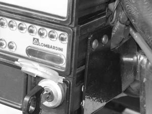
69 LTC Repair Lombardini Engine Troubleshooting a b d V 15/54 50 L c B 30 wc_gr wc_tx000364gb.fm 69
 from the keyswitch. 5.4.4 Unscrew the locking ring (b) and remove the keyswitch from the control panel. Reassembly: 5.")
70 Lombardini Engine Troubleshooting 5.4 Replacing Keyswitch LTC Repair See Graphic: wc_gr Disassembly: Shut down the engine and disconnect the battery Remove the six screws securing the control panel cover to the control panel Make note of the wire connections on the keyswitch and remove the wires (a) from the keyswitch Unscrew the locking ring (b) and remove the keyswitch from the control panel. Reassembly: Insert the replacement keyswitch into the control panel and secure it with the locking ring (b) Attach the wires (a) to the appropriate terminals of the keyswitch Secure the control panel cover to the control panel with the six screws. wc_tx000364gb.fm 70
71 LTC Repair Lombardini Engine Troubleshooting 5.5 Engine Cranks But Does Not Start Flowchart 4A Engine Cranks But Does Not Start Make sure that the machine has fresh fuel and that the fuel filter and fuel hoses are in good condition. Check battery condition. Replace battery. No Does battery provide correct voltage and CCA? Yes Checking Fuel System Check if fuel flows from inlet hose when engine is cranking. Check fuel solenoid wiring. No Does fuel flow from inlet hose? Gravity feed fuel through fuel intake hose. Yes Is fuel pump solenoid operating? Yes No Checking glow plugs Check glow plugs. Consult Lombardini engine repair manual. Yes Do glow plugs operate correctly? No Checking glow plug relay Check glow plug relay. Replace glow plugs. Yes Does glow plug relay operate correctly? No Replace glow plug relay. wc_gr wc_tx000364gb.fm 71

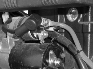
72 Lombardini Engine Troubleshooting 5.6 Checking Fuel System LTC Repair See Graphic: wc_gr WARNING Electric shock hazard. Only qualified personnel should conduct these tests. When troubleshooting Lombardini engines that crank but do not start, make the following checks Check that the battery is in good condition and that all connections are clean and tight. If the battery voltage falls below 11.5V, replace the battery Fill the fuel tank with fresh fuel and check that the fuel hoses and fuel filter are clean and in good condition Disconnect the fuel intake hose (a). Have a suitable container ready to catch the fuel. Place the keyswitch in the START position and check if the fuel flows from the hose. If fuel flows from the hose, reconnect the hose. If fuel does not flow from the hose, continue Disconnect the power lead (b) to the fuel solenoid. Place the keyswitch in the START position and check for battery voltage between the lead and ground. If battery voltage is not measured, check the continuity of wiring. See the Lombardini Engine Repair Manual for further information. If battery voltage is measured, check the power to the glow plugs. a b wc_gr wc_tx000364gb.fm 72

73 LTC Repair Lombardini Engine Troubleshooting 5.7 Checking Voltage to Glow Plugs (Lombardini 903 engines) See Graphic: wc_gr Place the keyswitch in the HEAT or START position Check for battery voltage between the R/Or glow plug wire (a) and ground. If battery voltage is not measured, check the continuity and connections of wiring. If battery voltage is measured, check the function of the glow plugs. a wc_gr wc_tx000364gb.fm 73
 See Graphic: wc_gr003229 To check the voltage to the glow plugs, carry out the")
 wire (a), place the keyswitch in the START position, and measure the voltage between the black wire and ground.")
 wire (b) and measure the voltage between it and ground.")
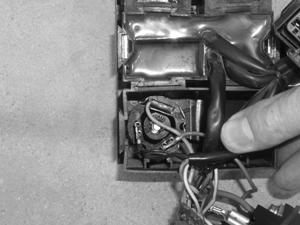
74 Lombardini Engine Troubleshooting LTC Repair 5.8 Checking Voltage to Glow Plugs (Lombardini 1003 engines) See Graphic: wc_gr To check the voltage to the glow plugs, carry out the following procedure: Disconnect the B (black) wire (a), place the keyswitch in the START position, and measure the voltage between the black wire and ground. There should be 12V (battery voltage approximately 12) measured. If 12V is measured, check the function of the glow plug. If 12V is not measured, continue Disconnect the B (black) wire (b) and measure the voltage between it and ground. There should be 12V (battery voltage approximately 12) measured. If 12V is measured, clean the connection points of the wires. Reconnect the wires and check the function of the glow plug. If 12V is not measured, check the glow plug relay. a b wc_gr wc_tx000364gb.fm 74

75 LTC Repair 5.9 Checking Glow Plug Relay See Graphic: wc_gr Lombardini Engine Troubleshooting Remove the screws securing the engine control panel. Leave all wiring connected to the control panel Rotate the control panel to gain access to the rear of the control panel. Remove the enclosure cover to access the glow plug relay Place the keyswitch in the START position. A working relay will click when the keyswitch is in the START position. Check the continuity across the blue (L) and black (B) wires when the keyswitch is in the START position. If there is no continuity, the relay is faulty; replace it Replacing Glow Plug Relay See Graphic: wc_gr Make note of the wire positions and disconnect all wires from the glow plug relay Bend back the tabs (a) securing the glow plug relay (b) and pull the glow plug relay from the enclosure. wc_tx000364gb.fm 75
76 Lombardini Engine Troubleshooting 5.11 Checking Glow Plugs LTC Repair See Graphic: wc_gr Remove the glow plug from the engine. Burn hazard. Glow plugs can reach temperatures up to 1200 F (649 C). Do not touch the element of the glow plug. Be extremely careful when testing the glow plug. WARNING Using 10-gauge wire, apply 12VDC to the glow plug positive on the upper portion and ground the base. If the glow plug does not heat (glow) within five seconds, replace the glow plug. Note: If any one of the glow plugs needs replacing, replace all of them. wc_tx000364gb.fm 76
77 LTC Repair 5.12 Engine Shuts Down Flowchart 5A Lombardini Engine Troubleshooting Engine Shuts Down Check engine oil level. Is machine oil level correct? No Fill machine with oil. Yes Check engine coolant level. Is engine coolant level correct? No Yes Checking oil pressure and coolant temperature switches Check wiring of oil pressure switch. Check wiring of coolant temperature switch. Fill engine with correct amount and type of coolant. Is oil pressure switch connected correctly? No Connect oil pressure switch and/or repair wiring. Yes Is coolant temperature switch connected correctly? No Connect coolant temperature switch and/or repair wiring. Yes Refer to the Lombardini repair manual. Call Wacker Service. wc_gr wc_tx000364gb.fm 77


78 Lombardini Engine Troubleshooting LTC Repair 5.13 Checking Oil Pressure and Coolant Temperature Switches See Graphic: wc_gr If the engine starts but shuts down after approximately 10 seconds, check the following Check the engine oil level and add oil if necessary. Also check the coolant temperature. If the coolant temperature is high, allow the engine to cool. Flush and fill the radiator with the correct coolant Check the wiring of the oil pressure switch (a) and the coolant temperature switch (b) (903 engines) or (c) (1003 engines). If the wiring of either switch is shorted to ground, the engine will shut down. Be sure the switches are functioning check each for continuity. The oil pressure switch is a normally closed (NC) switch that should have continuity when the engine is off. If the switch has no continuity when the engine is off, the switch is faulty; replace it. The high coolant temperature switch is a normally open (NO) switch. This switch should have no continuity when the engine is off. If this switch has continuity when the engine is off, it has shorted and is faulty; replace it. a b c wc_gr wc_tx000364gb.fm 78
79 LTC Repair 5.14 General Engine Troubleshooting Lombardini Engine Troubleshooting Possible Cause Symptom Engine will not crank Engine does not start Engine starts, but stops Poor acceleration Unsteady rpm Black smoke White smoke Blue smoke Low oil pressure Oil level rising Excessive oil consumption Wet exhaust Overheating Engine knocks Low fuel level Fuel supply/return lines clogged Clogged fuel tank vent Fuel pump faulty Fuel contaminated with air Unit injector(s) faulty/worn Unit injector settings incorrect Injection pump rack sticking Oil level too high Improper oil viscosity Oil diluted by fuel Oil pressure relief valve faulty Oil pick-up tube clogged Oil pump air contaminated at pick-up tube Glow plugs faulty Glow plug controller faulty Glow plug relay inoperable Starter defective wc_tx000364gb.fm 79
80 Lombardini Engine Troubleshooting LTC Repair Possible Cause Symptom Engine will not crank Engine does not start Engine starts, but stops Poor acceleration Unsteady rpm Black smoke White smoke Blue smoke Low oil pressure Oil level rising Excessive oil consumption Wet exhaust Overheating Engine knocks Battery voltage too low Battery/battery cable connections corroded Key switch defective Air filter clogged Excessive idle/light load operation Incomplete engine run-in Engine overloaded Excessive secondary load Valve lash insufficient/ excessive Injection timing out of spec - advanced Injection timing out of spec - retarded Governor linkage adjustment incorrect Governor spring fatigued or defective Idle rpm too low Piston rings worn or stuck Piston worn or damaged Cylinders worn or damaged Valve/valve guides worn wc_tx000364gb.fm 80
81 LTC Repair Possible Cause Lombardini Engine Troubleshooting Symptom Engine will not crank Engine does not start Engine starts, but stops Poor acceleration Unsteady rpm Black smoke White smoke Blue smoke Low oil pressure Oil level rising Excessive oil consumption Wet exhaust Overheating Engine knocks Valves sticking Bearings (main/rod) worn Governor/governor linkage malfunctioning Cylinder head gasket damaged Thermostat stuck or malfunctioning Engine seized Radiator clogged (external or internal) Coolant pump faulty Turbocharger faulty wc_tx000364gb.fm 81
82 Caterpillar Engine Troubleshooting 6. Caterpillar Engine Troubleshooting LTC Repair 6.1 Troubleshooting Flowcharts The troubleshooting flowcharts are designed to take you through the process of determining the source of a problem with engine starting or machine operation. Many of the tests involve live voltages and therefore should only be attempted by qualified personnel. Detailed procedures for carrying out the tests are included in this manual. All highlighted text within the flowcharts have matching sections in this manual. wc_tx000476gb.fm 82
83 LTC Repair Caterpillar Engine Troubleshooting 6.2 Engine Does Not Crank Flowchart 6A Engine Does Not Crank Check battery voltage. Does battery measure V? Yes Checking Keyswitch and Wiring Check connection of Or/B wire at starter solenoid. Also check wire connections at back of keyswitch. No Recharge or replace battery. Reconnect black wire. No Is the Or/B wire connected? Yes Clean and tighten connections. No Are connections clean and tight? Yes Check for battery voltage between terminal 30 of keyswitch and ground. Repair wiring from terminal 30 to battery. No Is battery voltage measured between 30 and ground? Yes Check for battery voltage between terminal AC of keyswitch and ground when key is placed in the START position. Check for battery voltage between Or/B wire at starter solenoid and ground when key is in START position. Yes Is battery voltage measured between AC and ground? Consult Caterpillar engine repair manual. Yes Is battery voltage measured between black wire and ground? No Replace keyswitch. No Repair/replace Or/B wire. wc_gr wc_tx000476gb.fm 83

84 Caterpillar Engine Troubleshooting 6.3 Checking Keyswitch and Wiring LTC Repair See Graphic: wc_gr Electric shock hazard. Only qualified personnel should conduct these tests. WARNING When troubleshooting CAT engines that do not crank, check that the Or/B wire (a) is connected to the starter solenoid Open the control panel and check that the wiring to the keyswitch is clean and tight. Check that the appropriate wires are connected to the proper terminals on the back of the keyswitch. Or/B Or a R/Or R/B R 17 A/C R/Or R/Or Y wc_gr wc_tx000476gb.fm 84
 from the keyswitch. 6.4.4 Unscrew the locking ring (b) and remove the keyswitch from the control panel. Reassembly: 6.")
85 LTC Repair 6.4 Replacing Keyswitch Caterpillar Engine Troubleshooting See Graphic: wc_gr Disassembly: Shut down the engine and disconnect the battery Remove the six screws securing the control panel cover to the control panel Make note of the wire connections on the keyswitch and remove the wires (a) from the keyswitch Unscrew the locking ring (b) and remove the keyswitch from the control panel. Reassembly: Insert the replacement keyswitch into the control panel and secure it with the locking ring (b) Attach the wires (a) to the appropriate terminals of the keyswitch Secure the control panel cover to the control panel with the six screws. wc_tx000476gb.fm 85
86 Caterpillar Engine Troubleshooting 6.5 Engine Cranks But Does Not Start Flowchart 7A LTC Repair Engine Cranks But Does Not Start Make sure that the machine has fresh fuel and that the fuel filter and fuel hoses are in good condition. Check battery condition. Replace battery. No Does battery provide correct voltage and CCA? Yes Checking Fuel Flow Check if fuel flows from banjo fitting when engine is cranking. Check fuel solenoid wiring. No Does fuel flow from the fitting? Gravity feed fuel through fuel intake hose. Yes Is fuel pump solenoid operating? Yes No Checking glow plugs Check glow plugs. Consult Caterpillar engine repair manual. Yes Do glow plugs operate correctly? No Replace glow plugs. wc_gr wc_tx000476gb.fm 86

87 LTC Repair 6.6 Checking Fuel Flow Caterpillar Engine Troubleshooting See Graphic: wc_gr To check the fuel flow on Caterpillar engines, carry out the following procedures Loosen the screw securing the banjo fitting (a) Place the keyswitch in the START position and check for fuel flow from the banjo fitting. If fuel flows from the banjo fitting, retighten the screw and check the operation of the glow plugs. If fuel does not flow from the banjo fitting, continue Place the keyswitch in the START position and check for battery voltage between the fuel solenoid R/W wire (b) and ground. If battery voltage exists between the R/W wire and ground, gravity feed fuel through the fuel intake line while cranking the engine using a 20- second on, 30-second rest sequence. Do this until fuel flows from the banjo fitting tighten the fitting as soon as fuel is seen flowing through it. Continue this process until the engine starts. After the engine starts, reconnect the fuel intake line to the tank. If battery voltage does not exist between the fuel solenoid R/W wire and ground, check the continuity of the wire. Repair or replace the wiring as needed. Refer to the Caterpillar Engine Repair Manual for further procedures. wc_tx000476gb.fm 87

88 Caterpillar Engine Troubleshooting 6.7 Checking Glow Plug Wiring LTC Repair See Graphic: wc_gr Place the keyswitch in the HEAT or START position Check for battery voltage between the R/Or glow plug wire (a) and ground. If battery voltage is not measured, check the continuity and connections of wiring. If battery voltage is measured, check the function of the glow plugs. 6.8 Checking Glow Plugs See Graphic: wc_gr Remove the glow plug from the engine. Burn hazard. Glow plugs can reach temperatures up to 1200 F (649 C). Do not touch the element of the glow plug. Be extremely careful when testing the glow plug. WARNING Using 10-gauge wire, apply 12VDC to the glow plug positive on the upper portion and ground the base. If the glow plug does not heat (glow) within five seconds, replace the glow plug. Note: If any one of the glow plugs needs replacing, replace all of them wc_tx000476gb.fm 88
89 LTC Repair 6.9 Engine Shuts Down Flowchart 8A Caterpillar Engine Troubleshooting Engine Shuts Down Check engine oil level. Is machine oil level correct? No Fill machine with oil. Yes Check engine coolant level. Is engine coolant level correct? No Yes Checking oil pressure and coolant temperature switches Check wiring of oil pressure switch. Check wiring of coolant temperature switch. Fill engine with correct amount and type of coolant. Is oil pressure switch connected correctly? No Connect oil pressure switch and/or repair wiring. Yes Is coolant temperature switch connected correctly? No Connect coolant temperature switch and/or repair wiring. Yes Refer to the Caterpillar repair manual. Call Wacker Service. wc_gr wc_tx000476gb.fm 89

90 Caterpillar Engine Troubleshooting LTC Repair 6.10 Checking Oil Pressure and Coolant Temperature Switches See Graphic: wc_gr If the engine starts but shuts down after approximately 10 seconds, check the following Check the engine oil level and add oil if necessary. Also check the coolant temperature. If the coolant temperature is high, allow the engine to cool. Flush and fill the radiator with the correct coolant Check the oil pressure switch (a) and coolant temperature switch (b) wiring. If the wiring of either switch is shorted to ground, the engine will shut down. Be sure the switches are functioning check each for continuity. The oil pressure switch is a normally closed (NC) switch that should have continuity when the engine is off. If the switch has no continuity when the engine is off, the switch is faulty; replace it. The high coolant temperature switch is a normally open (NO) switch. This switch should have no continuity when the engine is off. If this switch has continuity when the engine is off, it has shorted and is faulty; replace it. wc_tx000476gb.fm 90
91 LTC Repair 6.11 General Engine Troubleshooting Caterpillar Engine Troubleshooting Possible Cause Symptom Excess black smoke Blue smoke White smoke Increased oil consumption Unusual noises Lack of power Increased fuel consumption Overheating Hard starting/engine missing Debris in oil filter Dirty primary/secondary air cleaner Overfueling Overloading Worn rings/liners Worn seals Worn valve products Leaking head gasket Cracked head or liners Faulty injector Incorrect starting procedure Incorrect fuel injection timing Low quality fuel Worn or broken rings/liners Worn valve guides Malfunctioning fuel nozzle/injectors Worn piston pin bushings Worn rod/main bearings Too much valve lash Dirty fuel filter wc_tx000476gb.fm 91
92 Caterpillar Engine Troubleshooting LTC Repair Possible Cause Symptom Excess black smoke Blue smoke White smoke Increased oil consumption Unusual noises Lack of power Increased fuel consumption Overheating Hard starting/engine missing Debris in oil filter Incorrect adjustment of governor linkage Slipping torque converter Improper set point Fuel leak Plugged radiator core Incorrect adjustment or worn belts/ pulleys Low coolant level Malfunctioning temperature regulators Worn fuel injector pump Low octane level or water in fuel Low cranking speed Dirty entry Damaged bearings Coolant/fuel leakage into crankcase Extended oil change period Incorrect oil used wc_tx000476gb.fm 92
93 LTC Repair Caterpillar Engine Troubleshooting wc_tx000476gb.fm 93
94 Electrical Troubleshooting Procedures 7. Electrical Troubleshooting Procedures LTC Repair 7.1 Troubleshooting Methodology See Graphic: wc_gr If a lighting problem is not an obvious burnt bulb, engine speed, or wire fault, the cause of the problem will be associated with one of two things: a malfunctioning generator or faults in the circuit supplying voltage to the lights. By starting the troubleshooting procedures with the main circuit breaker you can determine whether the problem lies within the generator or the circuit supplying the lights. Note: You can quickly determine if the generator is functioning by measuring voltage at the receptacle. However, if voltage is not measured at the receptacle, it does not automatically mean the generator is not functioning - there may be problems with the receptacle. Therefore, it is best to start troubleshooting at the main circuit breaker. For troubleshooting a malfunctioning generator, you ll need to rule out a demagnetized rotor or problems with: the generator s capacitors, the stator windings, the rotor diodes, and finally the rotor windings. For troubleshooting the lighting circuit, you ll need to rule out problems with: the main circuit breaker, the terminal strip, the individual circuit breakers, the ballast, the control panel capacitors, and the wiring that connects all the components. Detailed procedures for making the tests are included in the upcoming sections of this manual. 7.2 Schematic Components See Graphic: wc_gr Ref. Description Ref. Description a Generator l Transformer b 20 Amp GFI outlet m Capacitor c Control box-lights n Ballasts d Quick disconnects p 25 Amp 2-pole circuit breaker e Terminal strip q Hourmeter f 20 Amp GFI circuit breaker r Alternator g 15 Amp circuit breaker s Control panel wc_tx000429gb.fm 94
95 LTC Repair 7.3 Schematic for 60 Hz Metal Halide 4-Light Units Electrical Troubleshooting 50Hz 60Hz 0 R B W G B d G W B G W B G W B G W B d d a c L R W/B R/B G Or W B s P/B Or W/B R/B e Or/B Or + - q Or Or G b B+ D+ W Or r wc_gr wc_tx000429gb.fm 95
96 Electrical Troubleshooting Procedures 7.4 Checking Continuity LTC Repair Conduct continuity tests when the engine is shut down. When checking continuity, use the Ohm setting on your multimeter. Place a lead of the multimeter on one end of the wiring or component and the other lead on the opposite end. If your meter reads OL or OPEN, there is no continuity and the wiring or component must be repaired or replaced. Note: Some multimeters also have an audio signal setting for determining continuity. This setting may also be used. If your meter reads less than 1.0 Ohm, or the audio signal sounds, the wiring or component has continuity and should be OK. If your meter reads more than 1.0 Ohm, the wiring is faulty and must be repaired or replaced. 7.5 Checking resistance 7.6 Checking voltage Conduct resistance checks when the engine is shut down. Use the Ohm setting on your multimeter. Conduct resistance checks when the machine is as close to 21 C (70 F) as possible. Higher temperatures can affect resistance values. Most digital multimeters have some internal resistance. To obtain your multimeter s internal resistance, simply cross the two leads of your multimeter and read the display. When conducting a resistance check, subtract your multimeter s internal resistance from the value you measure to obtain the true resistance of the component you are checking. Conduct voltage checks when the engine is running. Use the Volt setting on your multimeter. To prevent damage to your instrument, start with the highest scale available on your multimeter. Adjust to a lower scale as readings dictate. Use extreme caution when checking voltage to reduce the risk of electric shock. 7.7 Troubleshooting Flowcharts The troubleshooting flowcharts are designed to take you through the process of determining the source of a problem with engine starting or machine operation. Many of the tests involve live voltages and therefore should only be attempted by qualified personnel. Detailed procedures for carrying out the tests are included in this manual. All highlighted text within the flowcharts have matching sections in this manual. wc_tx000429gb.fm 96
97 LTC Repair Electrical Troubleshooting 7.8 Lights do not Illuminate Flowchart 1A Light(s) do not illuminate Is circuit breaker(s) in closed position? Yes No Close circuit breaker(s). Are bulbs black or burnt? No Yes Replace bulbs. Is wiring connected at quickdisconnects? No Connect quick-disconnects. Yes Checking engine speed Check engine speed. Is engine speed correct? Yes No Check engine rpm with a photo tach or vibrotach (Sirometer (wire whip)). If rpm is low: 1. Change engine air and fuel filters. 2. If necessary, reposition speed control lever on injection pump. Checking voltage to main circuit breaker Check voltage to main circuit breaker. Is 120V±10% measured? No Yes See Flowchart 1B See Flowchart 1C wc_gr wc_tx000429gb.fm 97
98 Electrical Troubleshooting Procedures 7.9 Lights do not Illuminate Flowchart 1B LTC Repair Checking outgoing voltage from main circuit breaker With lights disconnected at quickdisconnects, check outgoing voltage from main circuit breaker. Is 230V±10% measured? No Replace main circuit breaker. Yes Repair/replace wiring between main circuit breaker, terminal strip, and individual circuit breakers. Checking individual circuit breaker(s) With lights disconnected at quick-disconnects, measure incoming and outgoing voltage to/ from individual circuit breaker(s). No Is 120V±10% measured? Yes Replace the individual circuit breaker(s). No Is 120V±10% measured? Yes Checking incoming voltage to control panel capacitor(s) Checking outgoing voltage from control panel capacitor(s) With lights disconnected at quick-disconnects, check for 400V±10% from ballast(s) to control panel capacitor(s). With lights disconnected at quickdisconnects, check outgoing voltage from control panel capacitors. Yes Is 400V±10% measured? Is 400V±10% measured? No Replace capacitor(s). No Yes Checking wiring to/from ballast(s) Check voltage at quick disconnects. If 400V±10% is not measured, check continuity of the wiring beween the quick disconnects and the control panel capacitor(s). If 400V±10% is measured, check continuity of the wiring beween the quick disconnects and the light fixtures. Check the purple wires running to and the red wires running from the ballast(s). If the wires running to the ballast(s) are OK, there should be voltage (120±10%) to the ballast(s). If there is power to the ballast but no outgoing voltage (400±10%) from the ballast(s), the ballast(s) are malfunctioning; replace the ballast(s). wc_gr wc_tx000429gb.fm 98
99 LTC Repair 7.10 Lights do not Illuminate Flowchart 1C Electrical Troubleshooting Restoring Rotor Magnetism (Flashing) Remagnetize (flash) the rotor windings by connecting a 12V battery to capacitor leads #60 and #0. Start the engine and check voltage at generator terminal strip: T1 (red) to T2 (white); and T5 (black) to T2 (white). Checking stator windings. With engine shut down, remove red, white, and black wires from the terminal strip on the generator. Measure resistance across terminals T1 to T2: /-0.0 Ohms T4 to T5: /-0.0 Ohms #0 to #60: /-0.0 Ohms Is 30 40V measured? Yes No Replace stator. Consult factory. No Are all resistance values within range? Yes Stop the engine. Reconnect the #60 and #0 leads to the capacitor. Start the machine and check voltage at 120V receptacle. If 120V is not measured, check generator capacitors. If you measure low resistance, there is a short. Replace the complete generator end. Consult factory. With engine shut down Check continuity across terminals: T1 to ground; T5 to ground. No Does meter read "OPEN" or "OL"? Yes With engine shut down, check continuity across: For a thorough check of winding insulation, use a megger meter at 500V or have it tested by a motor repair shop. If after testing more than 2 M Ohms is not measured, replace the stator. Consult factory. If continuity tests are OK, stator is good. Check rotor and diodes. See Flowchart 1D. Yes #60 wire to ground; #60 wire to T1; #60 wire to T5. Does meter read "OPEN" or "OL"? No If you measure low resistance, there is a short. Replace the complete generator end. Consult factory. wc_gr wc_tx000429gb.fm 99
100 Electrical Troubleshooting Procedures 7.11 Lights do not Illuminate Flowchart 1D LTC Repair Checking rotor diodes With engine shut down, unsolder the wires from both rotor diodes. Using the diode scale ( ) on a multimeter, measure voltage across the diode. Reverse positions of the meter's leads and measure voltage again. Is V measured in one direction and open (OL) in the other? No Replace both diodes. Yes Checking continuity of rotor windings Check continuity of rotor windings by measuring resistance across lead and base of diode. Check both diodes. Is 2.2 Ohms or more measured? No Replace rotor. Consult with factory. Yes Check rotor winding continuity to ground by measuring resistance across lead wire and rotor shaft. Is there continuity? Yes Replace rotor. No For a thorough check of winding insulation, use a megger meter at 500V or have it tested by a motor repair shop. If after testing more than 2 M Ohms is not measured, replace the rotor. Consult factory. If continuity tests are OK, rotor is good. Return to Flowchart 1A. wc_gr wc_tx000429gb.fm 100
 tachometer,")
 Lombardini engines, (c) CAT engines].")

101 LTC Repair 7.12 Checking Engine Speed Electrical Troubleshooting See Graphic: wc_gr001625, wc_gr001634, and wc_gr Using either a photo (strobe) tachometer, a frequency meter (60Hz = 1800 rpm; 50Hz = 1500 rpm), or a vibration tachometer such as a Sirometer (a) (Wacker P/N ), check engine rpm. Refer to the instrument instructions. If necessary, adjust engine rpm using adjusting screw [(b) Lombardini engines, (c) CAT engines]. No load engine speed should be 1850 rpm for 60Hz and 1550 rpm for 50Hz models. NOTICE: Do not adjust the engine speed to be higher than that listed above. The electrical components are frequency sensitive. Running at higher speeds will lead to component damage. Also check the condition of the engine air, fuel, and oil filters. Change the filters if necessary. See maintenance section. a b wc_gr wc_gr c wc_gr wc_tx000429gb.fm 101
102 Electrical Troubleshooting Procedures LTC Repair 7.13 Checking Generator Voltage at Receptacle See Graphic: wc_gr WARNING Electric shock hazard. Only qualified personnel should conduct this test. A quick way to check the function of the generator is to check voltage at the receptacle. If the correct voltage is present, problems with the lights not functioning will be associated with the circuit from the main circuit breaker to the lights. Complete this test with the machine running and both the main circuit breaker and the receptacle circuit breaker in the ON position. If your machine includes an earth-leakage circuit breaker, also place it in the ON position Using the AC voltage setting on the multimeter, test the receptacle for 120V±10% on 60Hz models; 115V or 230V±10% on 50Hz models. If zero (0) volts is measured, it indicates there may be a problem with the generator. Before checking the generator, check the receptacle reset button if equipped on your machine model. Depress the button if it has popped out. If the reset button will not stay depressed, check the condition of the wiring to the receptacle. See section Checking Receptacle. If the correct voltage is measured, the generator is functioning. See the troubleshooting flowcharts for troubleshooting sequence. F m V F m V A A V- COM V- COM wc_gr wc_tx000429gb.fm 102
 securing the receptacle to the control panel cover and remove the receptacle.")
103 LTC Repair 7.14 Replacing Receptacle Electrical Troubleshooting See Graphic: wc_gr Carry out this procedure with the engine shut down. Removal: Remove the screws (a) securing the control panel cover and remove the cover Make note of the wire connections on the back of the receptacle. Loosen the screws securing the wires and remove the wires Remove the screws (b) securing the receptacle to the control panel cover and remove the receptacle. Installation: Mount the receptacle to the control panel cover Attach the wires to the appropriate terminals on the back of the receptacle Attach the control panel cover to the control panel. b a wc_gr wc_tx000429gb.fm 103
104 Electrical Troubleshooting Procedures 7.15 Checking Voltage to the Main Circuit Breaker LTC Repair See Graphic: wc_gr Electric shock hazard. Only qualified personnel should conduct this test. Do not perform this test if you or the machine are wet. WARNING Complete this test with the machine running Remove the control panel front cover Using the AC voltage setting on the multimeter, measure the voltage between the main circuit breaker at the red wire (a) and any of the neutral wires at the terminal strip (b). There should be 120V±10%. If 120V±10% was not measured, check the continuity of the red wire back to the generator. Then, check the condition of the generator by remagnetizing the rotor (flashing). See section Restoring Rotor Magnetism/(Flashing)/Checking Rotor Winding. If 120V±10% was measured, continue In the same manner, check the voltage between the main circuit breaker at the black wire (c) and any of the neutral wires at the terminal strip (b). If 120V±10% was not measured, check the continuity of the red wire back to the generator. Then, check the condition of the generator by remagnetizing the rotor (flashing). See section Restoring Rotor Magnetism/(Flashing)/Checking Rotor Winding. If 120V±10% was measured, the generator is functioning Continue troubleshooting by checking the voltage to the terminal strip and the function of the main circuit breaker. wc_tx000429gb.fm 104

105 LTC Repair Electrical Troubleshooting b a c F m V A V- COM wc_gr wc_tx000429gb.fm 105
106 Electrical Troubleshooting Procedures LTC Repair 7.16 Checking Voltage Between Main Circuit Breaker and Terminal Strip See Graphic: wc_gr Electric shock hazard. Only qualified personnel should conduct this test. Do not perform this test if you or the machine are wet. WARNING Complete this test with the machine running and the main circuit breaker in the ON position Remove the control panel front cover Using the AC voltage setting on the multimeter, measure the voltage between the R/G wire (a) and the B/G wire (c). There should be 240V±10%. If 240V±10% is measured, the proper voltage is reaching the terminal strip. If 240V±10% was not measured, continue Measure the voltage between the R/G wire (a) of the terminal strip and the neutral wires at the terminal strip (b). There should be 120V±10%. If 120V±10% is measured, the R/G wire is carrying the proper voltage. If 120V±10% was not measured, check the continuity of the R/G wire between the circuit breaker (d) and the terminal strip (a). Repair/replace the wire as needed Measure the voltage between the B/G wire (c) of the terminal strip and the neutral wires at the terminal strip (b). There should be 120V±10%. If 120V±10% is measured, the B/G wire is carrying the proper voltage. If 120V±10% was not measured, check the continuity of the B/G wire between the circuit breaker (e) and the terminal strip (c). Repair/replace the wire as needed. wc_tx000429gb.fm 106

107 LTC Repair Electrical Troubleshooting a c F m V A V- COM a c b F m V A V- COM a c d e wc_gr wc_tx000429gb.fm 107
108 Electrical Troubleshooting Procedures 7.17 Checking Individual Circuit Breakers LTC Repair See Graphic: wc_gr WARNING Electric shock hazard. Only qualified personnel should conduct this test. Do not perform this test if you or the machine are wet. Complete this test with the machine running. Test power to all circuit breakers or just the circuit breaker in question Unplug the light(s) at the upper mast quick-disconnect plugs Remove the control panel front cover Place the main circuit breaker in the ON position Using the AC voltage setting on the multimeter, test for 120V±10% incoming voltage by measuring across the input wires (a) (R/B, R, B/ W, or B) at the back of the circuit breaker(s) and neutral wires at the terminal strip (b). If 120V±10% is not measured, it indicates a problem with voltage reaching the circuit breaker. Check the continuity of the wiring between the terminal strip and the circuit breaker. Repair or replace the wiring as needed. If 120V±10% is measured at the circuit breaker, continue Place the circuit breaker being tested in the ON position and measure the voltage between the outgoing side of the circuit breaker (c) and neutral wires at the terminal strip (b). If 120V±10% is not measured, it indicates a problem with the circuit breaker. Check the continuity of the circuit breaker. Replace the circuit breaker if needed. If 120V±10% is measured, voltage is being supplied through the circuit breaker. Continue troubleshooting by checking the function of control panel capacitors. See section Checking Incoming Voltage to Control Panel Capacitor(s). wc_tx000429gb.fm 108


109 LTC Repair Electrical Troubleshooting b a c F m V A wc_gr V- COM wc_tx000429gb.fm 109
 from the control panel. 7.18.2 Place the circuit breaker ON-OFF switch in the ON position.")
110 Electrical Troubleshooting Procedures 7.18 Confirming a Malfunctioning Circuit Breaker LTC Repair See Graphic: wc_gr WARNING Electric shock hazard. Only qualified personnel should conduct this test. Complete this test with the engine shut down Remove the circuit breaker(s) from the control panel Place the circuit breaker ON-OFF switch in the ON position Using the Ohms scale on the multimeter, test the circuit breaker for continuity. If you measure no continuity ( OL or OPEN ), replace the breaker. If the breaker has continuity, re-install it Place the ON-OFF switch in the OFF position. wc_gr wc_tx000429gb.fm 110

111 LTC Repair Electrical Troubleshooting 7.19 Checking Incoming Voltage to Control Panel Capacitor(s) See Graphic: wc_gr WARNING Electric shock hazard. Only qualified personnel should conduct this test. Complete this test with the lights disconnected at the quickdisconnects (or disconnected at the junction box), the machine running, and the main circuit breaker in the ON position Remove control panel front cover Place the individual circuit breaker(s) to the light(s) in the ON position Using the AC voltage setting on the multimeter, test for 400V±10% incoming to the control panel capacitor(s) by measuring across the input wire (a) at the control panel capacitor(s) and the wires (b) of the terminal strip. If 400V±10% is not measured, it indicates faulty wiring to the ballast(s), faulty wiring to the control panel capacitors, or a failed ballast. See section Checking Wiring to/from Ballast(s). If 400V±10% is measured, the ballast(s) is functioning. Continue troubleshooting by checking the control panel capacitors. See section Checking Outgoing Voltage from Control Panel Capacitor(s). wc_tx000429gb.fm 111

112 Electrical Troubleshooting Procedures LTC Repair 7.20 Checking Outgoing Voltage from Control Panel Capacitor(s) See Graphic: wc_gr WARNING Electric shock hazard. Only qualified personnel should conduct this test. Complete this test with the lights disconnected, the machine running, and the main circuit breaker in the ON position. Test all capacitors or just the capacitor in question Remove the control panel front cover Place the individual circuit breaker(s) to the light(s) in the ON position Using the AC voltage setting on the multimeter, test for 400V±10% coming from the control panel capacitor(s) by measuring across the output terminal (a) of the control panel capacitor and the wires (b) of the terminal strip. If 400V±10% is measured, the control panel capacitor(s) is functioning. Continue troubleshooting by checking the wiring between the control panel capacitor(s) and the quickdisconnect(s). If 400V±10% is not measured, replace the capacitor(s). wc_tx000429gb.fm 112

113 LTC Repair Electrical Troubleshooting 7.21 Confirming a Faulty Control Panel Capacitor See Graphic: wc_gr Carry out this procedure with the engine shut down Remove the input and output wires from the capacitor. Note: The capacitor is shown with the resistor disconnected; the resistor may be left connected if desired Discharge the capacitor by placing the blade of an insulated screwdriver across the two spades of the capacitor Using a multimeter set to the Farad (F) or capacitance (C) scale (200 µf), measure the capacitor s capacitance. Each capacitor should measure 24±2 µf. If the reading is not within this range, replace the capacitor. F 20n 200n 2 µ 20 µ 200 µ 2000 µ 20m 2n 200p V A V- COM wc_gr wc_tx000429gb.fm 113
114 Electrical Troubleshooting Procedures 7.22 Checking Wiring to/from Ballast(s) LTC Repair See Graphic: wc_gr WARNING Electric shock hazard. Only qualified personnel should conduct this test. Complete this test with the machine shut down. At this stage, you should have measured voltage (120V±10%) to the circuit breaker(s) and no incoming voltage (400V±10%) to the control panel capacitors. Therefore, if the wiring to the ballast from the circuit breaker(s) is OK, the same voltage should be incoming to the ballast. In addition, if the wires from the ballast to the control panel capacitor(s) are OK, there should be voltage incoming to the control panel capacitors. If there is not, the ballast has failed; replace it. To check the wiring: Turn off the engine Remove the control panel front cover Remove the screws (a) which secure the control panel and the cover of the ballast box. Position the control panel/cover of the ballast box (b) so you can access the wiring to the ballast Check the B/Y (black-yellow) wire(s) (c) that run from the circuit breaker(s) to the ballast. Repair the wiring as needed Check the R (red) wire(s) (d) that run from the ballast to the control panel capacitor(s). Repair the wiring as needed Check the Y (yellow) wire(s) (e) that run from the ballast to the neutral of the terminal strip. Repair the wiring as needed If all wiring is OK, the ballast has failed; replace it If you had to repair any wiring, recheck the voltage incoming to the control panel capacitors. See section Checking Incoming Voltage to Control Panel Capacitor(s). wc_tx000429gb.fm 114

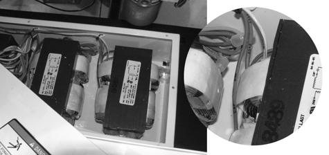
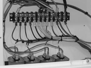
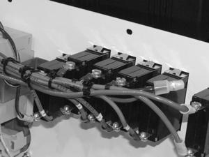
115 LTC Repair Electrical Troubleshooting a b c e d c e d wc_gr wc_tx000429gb.fm 115
116 Electrical Troubleshooting Procedures 7.23 Replacing Ballast LTC Repair See Graphic: wc _gr Removal: Shut down the engine and disconnect the battery Open the control panel and snip the wire ties (a) holding the ballast wires to the control panel Remove the six screws securing the control panel/ballast box cover. Pull the control panel/ballast box cover (b) off the ballast box just enough to allow access to the ballasts Remove the wiring (c, d, e) for each ballast being replaced Remove the hardware (f) securing the ballast (g) and remove the ballast from the ballast box. Reassembly: Secure the replacement ballast (g) in the ballast box with the hardware (f) Run the wires (c, d, e) up through the control panel and secure them to the proper locations Secure the control panel/ballast box cover (b) to the ballast box with the six screws Gather and organize the wires with new wire ties (a) Secure the control panel cover to the control panel with six screws. wc_tx000429gb.fm 116


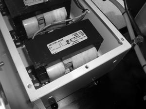
117 LTC Repair Electrical Troubleshooting b a e d g f c wc_gr wc_tx000429gb.fm 117
118 Electrical Troubleshooting Procedures LTC Repair 7.24 Restoring Rotor Magnetism (Flashing) / Checking Rotor Winding See Graphic: wc_gr Electric shock hazard. Only qualified personnel should conduct this test. WARNING These procedures require two 14-gauge jumper wires and a fullycharged 12V battery. If you measured 0 (zero) volts at the main circuit breaker, the generator may have lost its residual magnetism. Try restoring the magnetism (flashing) to the generator before conducting in-depth tests. Flashing the generator serves two purposes: 1) it restores rotor magnetism and 2) it confirms a working rotor (winding and diodes). By flashing the generator with a known DC voltage, a predictable output voltage is produced. For example, using a 12-volt battery, produces an output voltage of volts. Flash the generator before disassembly to confirm a malfunctioning rotor. Start this test with the engine shut down Unplug the #60 and #0 leads from the generator capacitor Using 14 gauge or larger wire, connect two jumper wires to the battery, one to each terminal. Once connected to the battery, do not allow the two jumpers to touch each other. WARNING Explosion hazard. Do not create sparks near battery Start the engine Connect the opposite end of the jumper wires to the #60 and #0 leads connect either wire to either lead. This is a non-polar connection Using the AC voltage setting on the multimeter, check the voltage across the terminal strip mounted on the generator: red (T5) to white (T4); black (T1) to white (T4). There should be volts measured in both cases. If you measure volts, the generator is functioning. Shut down the machine and disconnect the jumpers, first at the capacitor wires, then at the battery. If you do not measure volts, there is a problem. Shut down the engine and continue troubleshooting. See section Checking Stator Windings. wc_tx000429gb.fm 118
119 LTC Repair Electrical Troubleshooting G B R W T5 T1 F V 2 200m T2 T6 T4 T3 A V- COM V wc_gr wc_tx000429gb.fm 119
. 7.25.")
120 Electrical Troubleshooting Procedures 7.25 Checking Generator Capacitors LTC Repair See Graphic: wc_gr Carry out this procedure with the engine shut down. The capacitors of the electrical system are mounted to the top of the generator underneath the protective cover (a) With the unit off, remove the screws securing the protective cover and remove the cover Remove the leads from the capacitor and discharge it by placing the blade of an insulated screwdriver across the two spades of the capacitor Using a multimeter set to the Farad (F) or capacitance (C) scale (200 µf), measure the capacitor s capacitance. On systems with dual capacitors, each capacitor should measure 18±2 µf. If the reading is not within this range, replace the capacitor. Also see Alternative Capacitor Check. wc_tx000429gb.fm 120


121 LTC Repair 7.26 Alternative Capacitor Check Electrical Troubleshooting See Graphic: wc_gr and wc_gr An alternative capacitor check is to set the multimeter to the 10,000 Ohm scale when checking the capacitor. Observe the reading. If the reading starts out very low (5.0 Ohms) and continues to climb to an overload or open reading, the capacitor may be OK. Double check by installing the capacitor in a known-to-be-working Light Tower. If the known-to-be-working Light Tower operates correctly, the capacitor is OK. A second alternative check would be to try a known-to-be-working capacitor in the original Light Tower. If the Light Tower still does not produce power, the problem is within the generator. Check the stator and rotor. wc_tx000429gb.fm 121
122 Electrical Troubleshooting Procedures 7.27 Replacing Generator Capacitor(s) LTC Repair See Graphic: wc_gr Carry out this procedure with the engine shut down. Removal: Note the connection points of the #60 (#50 on 50Hz machines) and #0 wires and remove the wires (a) from the capacitor (b) Remove the jumper wire (c) connecting the two capacitors Cut the wire ties (d) and remove the capacitor(s). Installation: Insert the capacitors (b) and secure with new wire ties (d) Attach the #60 (#50 on 50Hz machines) and #0 wires to the appropriate terminals on the capacitor Attach the jumper wire (c). wc_tx000429gb.fm 122
123 LTC Repair Electrical Troubleshooting wc_tx000429gb.fm 123
124 Electrical Troubleshooting Procedures 7.28 Checking Stator Windings LTC Repair See Graphic: wc_gr The generator terminal block is located on top of the generator. When checking the stator windings at the terminal block, if there is any evidence of burned windings (such as melted wire insulation or odor), replace the generator. Carry out the following tests with the engine shut down. Note: Before making resistance measurements, determine the value of your meter s internal resistance by touching the meter s leads. Subtract this value from the values you measure Remove the RED, BLACK, and WHITE wires from the generator terminal block Remove the leads from the capacitors and place an insulated screwdriver across the capacitors to discharge them Using the Ohm (resistance) setting on the multimeter, measure the resistance T1 to T2. Also measure resistance T4 to T5. In both cases the resistance measured should be /-0.0 Ohms. Measure the resistance #60 lead to #0 lead. The resistance measured should be /-0.0 Ohms. If there is no continuity (meter reads OPEN or OL ), replace the stator Using the Ohm setting on the multimeter, measure the resistance T1 to ground, and T5 to ground. The multimeter should read OPEN or OL for both tests. If the meter does not read OPEN, replace the entire generator Using the Ohm scale on the multimeter, measure resistance #60 lead to ground, #60 lead to T1, and #60 lead to T5. The multimeter should read OPEN or OL for all three tests. If the meter does not read open, replace the entire generator. Consult with factory to confirm. Note: Do not touch the machine frame when making this test. A reading error will occur. Note: A meter reading of 2 megohms (2 M Ohms) or larger is acceptable. For a more thorough insulation test, use a megger meter capable of 500 Volts or have a motor repair shop test it. If readings are 2 megohms or greater, the stator is good. If readings are less than 2 megohms, replace the generator end. Consult factory to confirm. wc_tx000429gb.fm 124
125 LTC Repair Electrical Troubleshooting G R B W T2 T6 T5 T1 T4 T F V 2 200m A V- COM T1 to T2: /-0.0 T4 to T5: /-0.0 #0 to #60: /-0.0 T1 to ground: OL T5 to ground: OL #60 to ground: OL #60 to T1: OL #60 to T5: OL 60 0 wc_gr wc_tx000429gb.fm 125
126 Electrical Troubleshooting Procedures 7.29 Removing/Installing Caterpillar Engine with Generator LTC Repair See Graphic: wc_gr Removal: Shut down the engine and disconnect the battery Remove the top enclosure cover. See section Replacing Fuel Tank Remove the four screws (a) securing the capacitor cover (b) and remove the capacitor cover Note the position of the wiring (c) and remove the wiring from the capacitor terminal strip. Also remove the screw securing the ground wire (d) Remove the four bolts (e) securing the muffler (f) and remove the muffler Disconnect the ground wires (g) from the engine Disconnect the wiring harness from the glow plugs (h), fuel pump (i), and the oil pressure sensor (j). Also disconnect the wiring harness from the coolant temperature sensor (k), the connector plug (l), and the starter motor (m) Disconnect the coolant overflow reservoir tube at the radiator (n) Remove the four nuts and washers located underneath the frame that secure the shock mounts to the frame Using an appropriate crane or hoist, lift the engine/generator assembly from the machine. Reassembly: Using an appropriate crane or hoist, position the engine/generator assembly into the machine Secure the engine/generator assembly to the machine frame Connect the coolant overflow reservoir tube to the radiator (n) Connect the wiring harness to the glow plugs (h), fuel pump (i), and the oil pressure sensor (j). Also connect the wiring harness to the coolant temperature sensor (k), the connector plug (l), and the starter motor (m) Connect the ground wires (g) to the engine Secure the muffler with four bolts (e) Connect the wiring (c) to the capacitor terminal strip. Also connect the screw securing the ground wire (d) Secure the capacitor cover (b) to the generator Re-install the fuel tank. See section Replacing Fuel Tank. wc_tx000429gb.fm 126

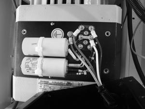
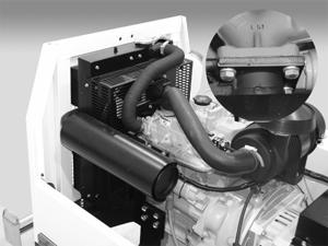
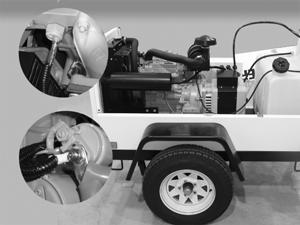
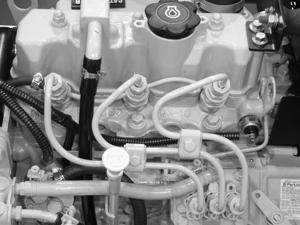
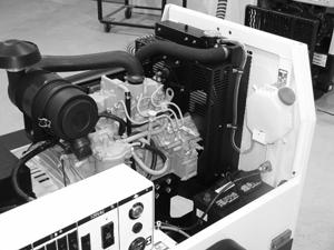
127 LTC Repair Electrical Troubleshooting 250 kg (550 lbs.) wc_gr g d b a R W B c f e h i j k n l m wc_gr wc_tx000429gb.fm 127
128 Electrical Troubleshooting Procedures 7.30 Removing/Installing Lombardini Engine with Generator LTC Repair See Graphic: wc_gr Removal: Shut down the engine and disconnect the battery Remove the top enclosure cover. See section Replacing Fuel Tank Remove the four screws (a) securing the capacitor cover (b) and remove the capacitor cover Note the position of the wiring (c) and remove the wiring from the capacitor terminal strip. Also remove the screw securing the ground wire (d) Remove the three bolts (e) securing the muffler (f) and remove the muffler Disconnect the ground wires (g) from the engine Disconnect the orange wire (h) from the connector near the engine control box. Disconnect the wiring harness from the coolant high temperature switch (i) and the coolant temperature thermistor (j). Also disconnect the wires (k & l) at the alternator Disconnect the coolant overflow reservoir tube at the radiator Remove the four nuts and washers located underneath the frame that secure the shock mounts to the frame Using an appropriate crane or hoist, lift the engine/generator assembly from the machine. Reassembly: Using an appropriate crane or hoist, position the engine/generator assembly into the machine Secure the engine/generator assembly to the machine frame Connect the coolant overflow reservoir tube to the radiator Connect the orange wire (h) to the connector near the engine control box. Connect the wiring harness to the coolant high temperature switch (i) and the coolant temperature thermistor (j). Also connect the wires (k & l) at the alternator Connect the ground wires (g) to the engine Secure the muffler with three bolts (e) Connect the wiring (c) to the capacitor terminal strip. Also connect the screw securing the ground wire (d) Secure the capacitor cover (b) to the generator Re-install the top enclosure cover. See section Replacing Fuel Tank. wc_tx000429gb.fm 128

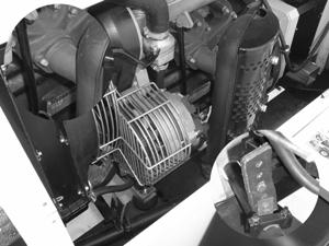
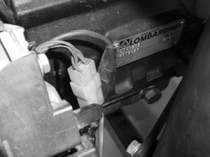
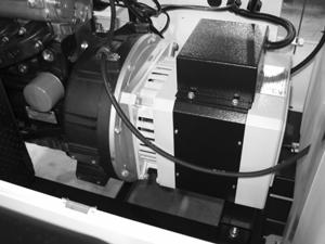
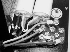
129 LTC Repair Electrical Troubleshooting 50Hz 250 kg (550 lbs.) d wc_gr c L Br b 60Hz d a R W B c e h g e j k i j wc_gr wc_tx000429gb.fm 129
130 Electrical Troubleshooting Procedures LTC Repair 7.31 Separating Stator Assembly from Engine/Rotor Assembly See Graphic: wc_gr Note: The fit between the rotor bearing and the stator housing is tight. The tight fit prevents the bearing from spinning in the housing There are two methods to separate the stator assembly from the engine/rotor assembly. The first method involves creating a special pusher tool. When using either method, support the stator assembly with an appropriate strap and hoist. Method Using an appropriate strap (a) and hoist, support the generator end Using an approximately 3" x 3" (8cm x 8cm) piece of steel or aluminum plate (b), drill a pilot hole in the center of the plate to accommodate an M14 thread. Tap the hole in the plate with M14 threads Drill two holes in the plate whose placement matches those in the stator housing (f) Tap the holes (f) in the stator housing and using two screws (c) of the same thread, secure the 3" x 3" plate to the stator housing Remove the M8 bolts (d) securing the engine adapter flange to the engine Using an M14 bolt (e), thread it into the M14 threaded hole of the plate and slowly pull the stator assembly from the engine/rotor assembly. a f b d c e wc_gr wc_tx000429gb.fm 130
 securing the engine adapter flange to the engine. 7.31.")
131 LTC Repair See Graphic: wc_gr Electrical Troubleshooting Method Remove the M8 bolts (a) securing the engine adapter flange to the engine Using two screwdrivers (b) or equivalent pry bars, carefully pry the stator assembly from the engine/rotor assembly. wc_tx000429gb.fm 131


132 Electrical Troubleshooting Procedures LTC Repair 7.32 Remounting Stator Assembly to Rotor/Engine Assembly See Graphic: wc_gr and wc_gr Note: The fit between the rotor bearing and the stator housing is tight. The tight fit prevents the bearing from spinning in the housing While supporting the stator assembly with an appropriate strap and hoist, slide the stator assembly over the rotor/engine assembly Assemble an M10 nut (a) and washer (b) to an M10x80 bolt (c) Thread the bolt into the rotor through the hole in the stator housing Thread the nut against the stator housing and slowly tighten the nut to push the stator housing onto the rotor and bearing assembly (f). Continue until engine adapter flange comes into contact with engine. Do not overtighten Secure the engine adapter flange to the engine with M8 bolts (d). Torque the bolts to 25 ft.lbs. (35 Nm). Note: Failure to install the stator in the above manner may result in a cocked rotor bearing which can result in premature bearing wear or engine bearing wear. If there is any doubt that the bearing is seated correctly, place a block of wood over the end of the stator housing and strike it firmly with a hammer; this will release the bearing. 2mm f wc_gr wc_tx000429gb.fm 132

133 LTC Repair 7.33 Checking Rotor Diodes Electrical Troubleshooting See Graphic: wc_gr There are two diodes on the rotor assembly. The engine/generator assembly must be removed and the stator must be separated from the rotor to check the function of the diodes. When checking, be sure to check both diodes Unsolder the two wires from the terminal end of each diode Using the diode setting on the multimeter, measure the voltage across the diode terminal and the base of the diode. Reverse the leads of the meter and measure the voltage again. One of the readings should be between V. With the meter leads reversed, the other reading should be OL or a very large reading (for example, 2.0 MV) If your readings do not match those listed above, replace both diodes. Unscrew the diode to remove it. wc_tx000429gb.fm 133

134 Electrical Troubleshooting Procedures 7.34 Checking Rotor Windings LTC Repair See Graphic: wc_gr After checking the two rotor diodes, check the rotor windings. The engine/generator assembly must be removed and the stator must be separated from the rotor to check the rotor windings Unsolder the two rotor winding wires from the terminal end of each diode Using the Ohms setting on the multimeter, measure the resistance across the wires and the base of the corresponding diode. Each wire reading should be /-0.0 Ohms or greater. If your readings are not /-0.0 Ohms or greater, replace the generator Check the resistance of all four rotor windings in this manner Also check the resistance across the wires and the rotor shaft. If your readings are not OL, or greater than 2 megohms (2M Ohms), replace the generator. Confirm with factory before replacing Check all four wires in this manner. For a more thorough insulation test, use a megger meter capable of 500 Volts or have a motor repair shop test it. If readings are 2 megohms (2M Ohms) or greater, rotor is good. If readings are less than 2 megohms, replace the generator end. Consult factory to confirm. wc_tx000429gb.fm 134
. Make sure the discs are seated completely and evenly into the engine flywheel.")
135 LTC Repair 7.35 Removing/Installing Rotor Electrical Troubleshooting See Graphic: wc_gr Removal Remove the M8 bolts (a) securing the rotor flex discs (b) to the engine flywheel (c) and remove the rotor assembly. Installation Secure the rotor flex discs to the engine using M8 bolts. Torque the bolts to 15 ft.lbs. (21 Nm). Make sure the discs are seated completely and evenly into the engine flywheel. wc_tx000429gb.fm 135
136 Electrical Troubleshooting Procedures 7.36 No Voltage at Receptacle Flowchart 2A LTC Repair No Voltage at Receptacle Make sure the main circuit breaker and the receptacle's circuit breaker are in the ON position. Checking voltage to main circuit breaker Check voltage to main circuit breaker. Checking voltage at receptacle Check voltage at receptacle. See Flowchart 1C No Is 120V±10% measured? Yes Is 120V±10% measured? No Checking receptacle circuit breaker Measure incoming and outgoing voltage to/from earth-leakage circuit breaker. Repair/replace wiring between main circuit breaker, terminal strip, and receptacle circuit breaker. No Is 120V±10% incoming measured? Yes Replace receptacle circuit breaker. No Is 120V±10% outgoing measured? Yes Checking incoming voltage to receptacle Measure incoming voltage at back of receptacle. If 120V±10% is not measured, repair/replace wiring between receptacle circuit breaker and receptacle. If 230V±10% is measured, replace the receptacle. wc_gr wc_tx000429gb.fm 136


137 LTC Repair Electrical Troubleshooting 7.37 Checking Voltage at Receptacle See Graphic: wc_gr WARNING Electric shock hazard. Only qualified personnel should conduct this test. Complete this test with the machine running and both the main circuit breaker and the receptacle circuit breaker in the ON position Using the AC voltage setting on the multimeter, test the receptacle for 120V±10% on 60Hz models; 230V±10% on 50Hz models If zero (0) Volts is measured, check the receptacle reset button if equipped on your machine model. Depress the button if it has popped out. If the reset button will not stay depressed, check the condition of the wiring to the receptacle If the wiring is OK, test for voltage at the back of the receptacle. If 120V±10% on 60Hz machines or 230V±10% on 50Hz machines is measured, replace the receptacle. F V F V m 200m A A V- COM V- COM wc_gr wc_tx000429gb.fm 137
138 Electrical Troubleshooting Procedures 7.38 Checking Receptacle s Circuit Breaker LTC Repair See Graphic: wc_gr WARNING Electric shock hazard. Only qualified personnel should conduct this test. Complete this test with the machine running Using the AC voltage setting on the multimeter, measure the incoming voltage to the receptacle s circuit breaker by measuring between the black-yellow wire (a) and the neutral wires (b) of the terminal strip. There should be 120V±10%. If 120V±10% is not measured, the receptacle s circuit breaker is not receiving voltage. Check the condition of the wiring between the receptacle s circuit breaker and the terminal strip. Repair/ replace the wiring as needed. If 120V±10% is measured, continue Make sure the receptacle s circuit breaker is in the ON position Measure the outgoing voltage from the receptacle s circuit breaker by measuring between the black-yellow wire (c) and the neutral wires (b) of the terminal strip. There should be 120V±10%. If 120V±10% is not measured, the receptacle s circuit breaker is not functioning. Confirm that receptacle s circuit breaker is malfunctioning by checking its continuity. Replace the circuit breaker if needed. If 120V±10% is measured, continue troubleshooting by checking the wiring to the receptacle. wc_tx000429gb.fm 138
139 LTC Repair Electrical Troubleshooting b a F m V A c V- COM wc_gr wc_tx000429gb.fm 139
140 Electrical Troubleshooting Procedures 7.39 Troubleshooting the Power Winch LTC Repair See Graphic: wc_gr Lower the tower Lower the mast assembly into the cradle Turn off the engine Be sure the machine s battery is fully charged (approximately 12V) Remove the four screws (a) which secure the cover of the winch and remove the cover. Pinching hazard. Use extreme care when operating the winch with its cover removed. CAUTION Disconnect the red and black wires at the motor (b) Place the appropriate winch switch (c) in the up or down position, and check for battery voltage (approximately 12) between the red and black wires. If 12V is measured, the power winch is receiving the correct voltage. Thus, the power winch should operate. If power winch does not operate, replace it. If 12V is not measured, continue Remove the control panel (d) from the control box Check for battery voltage (approximately 12V) between terminals B1 and B2 of the winch switch (e). If 12V is measured, the winch switch is receiving the correct voltage. Thus, the power winch switch should operate. Check for battery voltage between terminals A1 and A2 for both the up and the down positions of the winch switch. If the winch switch does not operate, replace it. If 12V is not measured, continue Locate the circuit breaker (f). Remove the tape and check for battery voltage between the output side (g) of the circuit breaker and ground. If 12V is measured at the output side of the circuit breaker but not at the winch switch, the wiring between the circuit breaker and the winch switch has failed; repair or replace the wiring. If 12V is not measured, continue Check for battery voltage between the input side of the circuit breaker and ground. If 12V is measured between the input side and ground but not the output side and ground, the circuit breaker has failed; replace it. wc_tx000429gb.fm 140


141 2 200m 2 200m LTC Repair Electrical Troubleshooting If 12V is not measured, the wiring from the starter solenoid or the wiring from the battery to the starter solenoid has failed. Check the wiring and repair or replace it as necessary. F V A V- COM a b d c F V A e V- COM f g h wc_gr wc_tx000429gb.fm 141
142 Electrical Troubleshooting Procedures Notes LTC Repair wc_tx000429gb.fm 142
143 LTC Repair Disassembly/Assembly Procedures 8. Disassembly/Assembly Procedures 8.1 Tools 8.2 Ordering Parts Because all possible problems encountered while repairing the machine cannot be anticipated, it is up to the mechanic to use common sense and good judgement in tool selection. The use of any special tools is recommended only for those operations where the use of conventional tools proves inadequate. Before substituting another tool or procedure, you should be satisfied that neither personal injury nor damage to the component will result. The repair procedures contained in this manual do not include part numbers. For parts replacement information, refer to the Parts Book originally supplied with the machine. If the original Parts Book has been lost, a replacement may be ordered from Wacker Neuson Corporation. When ordering a replacement Parts Book, please list the model number, item number, revision level, and serial number of the machine. Parts Books are also available on the Wacker Neuson Corporation Web site. See Enter the site as a visitor. 8.3 Reference Numbers ( ) 8.4 Weight Block Repair procedures contain reference numbers enclosed in parentheses ( ). These numbers refer to the item numbers shown on the assembly drawings and other detailed drawings. They are included to aid the mechanic in identifying parts and assembling components. See Graphic: wc_gr The weight block symbol gives an approximate weight measurement to aid the mechanic when lifting/hoisting larger components. 250 kg (550 lbs.) wc_gr wc_tx000428gb.fm 143
144 Disassembly/Assembly Procedures 8.5 Light Assembly LTC Repair See Graphic: wc_gr Removal: Unplug the light at the quick disconnect (a) Remove the T-handle (b) and the cone washer (c). Also remove the nut (d) and the washer (e) securing opposite end Pull the light assembly (f) from the bracket (g) Remove the screws (h) securing the flange rings (i) and remove the flange rings Remove the lens (j) with the gasket (k) attached. Remove the gasket from the glass if replacing the gasket or lens Remove the hardware securing the bulb stabilizer (l) on one side. Once removed, swing the bulb stabilizer to the side and unscrew the bulb (m) Remove the four screws (n) and the flange (t) securing the ceramic fixture assembly (o) to the reflector and remove the ceramic fixture assembly including the gasket (s) Remove the two screws securing the cover to the connector box and cut the black (p) and white wires (q) near the crimp nuts Remove the two screws (r) securing the ceramic fixture to the housing and remove the ceramic fixture. Installation: Slide the wiring of the replacement ceramic fixture through the housing and into the connector box. Secure the ceramic fixture to the housing with the two screws (r) Connect the black wire (p) from the new ceramic fixture to the black wire in the connector box. Connect the white wire (q) from the new light fixture to the white wire of the connector box. Secure the wires with new crimp nuts Replace the cover of the connector box and secure it with two screws Secure the ceramic fixture assembly (o), the gasket (s), and the flange (t), to the reflector using four screws (n) Insert the bulb and secure it with the bulb stabilizer (l) Install the gasket (k) around the lens (j) and secure the lens to the reflector with the flange ring (i) and screws (h) Mount the light assembly (f) to the bracket (g) and mount the assembly to the upper mast. Connect wiring at the quick disconnect (a). wc_tx000428gb.fm 144
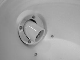
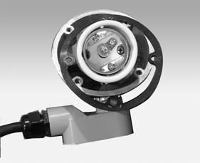
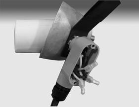
145 LTC Repair Disassembly/Assembly Procedures b c a k e d g j h i f l n o m t r p s q wc_gr wc_tx000428gb.fm 145
146 Disassembly/Assembly Procedures 8.6 Tower Assembly Exploded View LTC Repair 250 Kg (550 lbs.) a b c d e f p i n g h k l wc_gr j m wc_tx000428gb.fm 146
147 LTC Repair 8.7 Tower Assembly List of Parts Disassembly/Assembly Procedures Ref. Description Ref. Description a Main mast (4-inch tube) i Mid mast (3-inch tube) b Winch j Cross member c Main mast cable k Upper mast (2-inch tube) d Main mast pulley l Junction box e Main mast guide m Cross member wiring cable clamps f Upper mast cable n Mid-mast wiring cable clamps g Mid-mast guide o Retaining bolt h Mid-mast pulley p Eyebolt or U-bolt 8.8 Upper Mast See Graphic: wc_gr and wc_gr Disassembly: Turn the lights off, turn the unit off, and lower the mast assembly into the cradle before performing this procedure. Place the Light Tower in a position with enough room so that the masts may be extended fully while in the down position. The mast cable system consists of two cables: one (c) connected to the winch mounted on the main mast that raises the mid mast, and a second (f) that is connected to both the upper mast and the lower mast. This second cable raises the upper mast as the mid mast is being raised Disconnect the wiring at each light fixture s quick-disconnect or at the junction box. Then, remove each light fixture. Store the light fixtures in a safe place When replacing the upper-mast cross member (j) only, disconnect the wiring cable clamps (m) and the junction box (l), then simply replace the cross member. When replacing cables or portions of the mast, the junction box may remain mounted to the cross member. Disconnect the wiring cable clamp (n) from the mid mast, then disconnect the cross member with the box attached and place it near the trailer. wc_tx000428gb.fm 147
148 Disassembly/Assembly Procedures LTC Repair Using the tongue-mounted winch, raise the tower so that the masts are approximately two inches (5 cm) above the cradle locking pin (aa) On machines using rivets*, drill out the rivets (bb) securing the five guides (g) to the mid mast. On machines using screws, remove the screws securing the five guides to the mid mast. *Note: Replacement screws will be required for reassembly Pull the upper mast partially (2 6 feet (1 2 m)) out of the mid mast Make note of the upper mast cable (cc) as it passes around the midmast pulley (dd) then between the mid-mast pulley and the guide hardware (ee). Remove the mid-mast pulley. Remove the guide hardware only if it requires replacement Remove the upper mast (k) completely from the mid mast Remove the hardware securing the cable eyebolt (p) to the main mast Remove the hardware securing the cable to the upper mast. Once free from the upper mast, run the cable back through the opening near the guide screw in the mid mast and remove cable completely from the machine. WARNING Reassembly: Replacement cables must be of the exact length of the original equipment. Using shorter cables may cause severe personal injury Mount the mid-mast pulley (dd). Run the upper-mast cable (cc) around the mid-mast pulley (dd) and between the pulley and the guide hardware (ee). Attach the cable to the upper mast (k) Slide the upper mast into the mid mast (i) Attach the five guides (g) using new self-tapping screws. Position the guides so that the self-tapping screws thread themselves into the smaller side of the tapered hole in the guide. Note: Limit reuse of the guides to one time. The guides must be installed because they serve as safety stops. Without them properly installed, the upper-mast section could be pulled out of the mid-mast section, possibly causing severe bodily harm Secure the cable eyebolt (p) to the main mast Mount the light fixtures and reconnect the wiring. WARNING wc_tx000428gb.fm 148

. b a wc_gr003161 wc_tx000428gb.")
149 LTC Repair Disassembly/Assembly Procedures aa bb dd ee cc wc_gr When installing the junction box, be sure to include the gasket (a) and use a silicon-based sealant on all hardware and plugs (b). b a wc_gr wc_tx000428gb.fm 149
150 Disassembly/Assembly Procedures 8.9 Mid Mast LTC Repair See Graphic: wc_gr and wc_gr Disassembly: Turn the lights off, turn the unit off, and lower the mast assembly into the cradle before this performing procedure. Place the Light Tower in a position with enough room so that the masts may be extended fully while in the down position. The mast cable system consists of two cables: one (c) connected to the winch mounted on the main mast that raises the mid mast; and a second (f) that is connected to both the upper mast and the main mast. This second cable raises the upper mast as the mid mast is being raised Disconnect the wiring at each light fixture s quick-disconnect or at the junction box. Then, remove each light fixture. Store the light fixtures in a safe place Using the tongue-mounted winch, raise the tower just so that the masts are free from the cradle locking pin Remove the upper-mast cross member (j) with the junction box attached Remove the upper-mast cable eyebolt (p) Using the mast-mounted winch, back off the tension of the cable until the cable may be unwound from the mast-mounted winch. Unwind and remove the cable from the mast-mounted winch On machines using rivets*, drill out the rivets (ww) securing the five guides to the main mast. On machines using screws, remove the screws to remove the five guides. *Note: Replacement screws will be required for reassembly Remove the stop screw (xx) Remove the main-mast pulley (cc) Using the aid of an assistant or appropriate hoist, pull both the upper and mid-mast sections from the main mast Remove the hardware securing the cable to the mid mast and remove the cable from the mid mast. If the mid mast requires replacement, continue Remove the five guides (g) from the inside of the end of the mid mast (i) Remove the mid-mast pulley (h) Pull the upper mast (k) free of the mid mast. wc_tx000428gb.fm 150
 3/4 of the way, approximately 7 feet (2.3 m). 8.9.16 Attach the five guides (g) using the new self-tapping screws.")
151 LTC Repair Disassembly/Assembly Procedures WARNING Reassembly: Replacement cables must be of the exact length of the original equipment. Using shorter cables may cause severe personal injury Attach the cable to the mid mast Hold the cable snug to upper side of the mid mast and insert it into the main mast (a) 3/4 of the way, approximately 7 feet (2.3 m) Attach the five guides (g) using the new self-tapping screws. Position the guides so that the self-tapping screws thread themselves into the smaller side of the tapered hole in the guide. Note: Limit reuse of the guides to one time. The guides must be installed because they serve as safety stops. Without them properly installed, the mid-mast section could be pulled out of the main-mast section, possibly causing severe bodily harm Route cable (yy) around the main-mast pulley (zz) and install the mainmast pulley Slide the mid mast completely into the main mast Attach the cable to the winch See section Upper Mast for installing the upper mast. WARNING wc_tx000428gb.fm 151
152 Disassembly/Assembly Procedures 8.10 Main Mast LTC Repair See Graphic: wc_gr02434 Disassembly: Turn the lights off, turn the unit off, and lower the mast assembly into the cradle before performing this procedure. Place the Light Tower in a position with enough room so that the masts may be extended fully while in the down position. The mast cable system consists of two cables: one connected to the winch mounted on the main mast that raises the mid mast; and a second that is connected to both the upper mast and the main mast. This second cable raises the upper mast as the mid mast is being raised Remove the upper mast and the mid mast from the main mast. See section Mid Mast Disconnect the wiring from the control panel by: Snipping the wire ties (a). Disconnecting the wires from the capacitors (b). Disconnecting the wires from terminal strip (c) Loosen the clamps (d & e) securing the tower supply cable. One is located on the control box and the other is on the front enclosure panel Remove the cable clip (f) from the underside of the enclosure top Thread the tower supply cable through the eyes (g) on the side of the main mast Remove the cable clip (h) attached to the end of the main mast Tighten the adjusting knob (i) so that the main mast will not spin when loosening the nut (j) securing the main mast to the main cradle. Remove the nut securing the main mast to the main cradle Loosen the adjusting knob Using an appropriate crane or hoist, lift the main mast up and out of the main cradle and free from the machine. wc_tx000428gb.fm 152

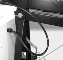
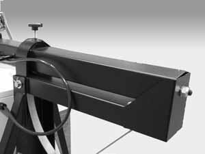
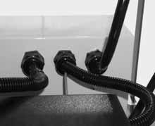
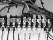
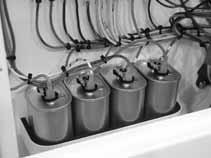
153 LTC Repair Disassembly/Assembly Procedures d a c b ce f g i j h wc gr wc_tx000428gb.fm 153
154 Disassembly/Assembly Procedures LTC Repair See Graphic: wc_gr Reassembly: Grease the adjusting point circle (a) of the main cradle and the bottom pivot point (b) of the main mast Using an appropriate crane or hoist, lift the main mast onto the top of the generator enclosure. Slide the bottom of the main mast into the main cradle Secure the main mast to the main cradle with the washer and nut (c) Position the cable clip (d), on the tower supply cable, just below the lower curled portion of the cable. Then, secure the cable clip to the end of the main mast Thread the tower supply cable through the eyes (e) on the main mast Thread the tower supply cable through the clamp (f) at the front of the machine; leave a loop (g) of cable large enough so there is enough slack in the cable to raise the mast Feed the tower supply cable into the control box and connect the wires to the appropriate locations (h & i). Refer to the wiring diagram. Tighten the cable clamp (j), organize the wires with new wire ties (k), and re-install the control panel cover Secure the tower supply cable in the cable clip (l) and secure the cable clip to the underside of the top enclosure panel. wc_tx000428gb.fm 154
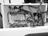
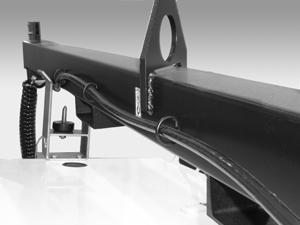
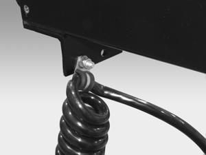
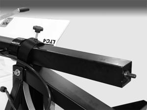
155 LTC Repair Disassembly/Assembly Procedures c a b d f g k h e i j l wc_gr wc_tx000428gb.fm 155
156 Disassembly/Assembly Procedures 8.11 Replacing Cable and Winch on Power Winch Models See Graphic: wc_gr LTC Repair Removal: Lower the tower Lower the mast assembly into the cradle Turn off the engine Remove the four screws (a) which secure the cover of the winch and remove the cover. Pinching hazard. Use extreme care when operating the winch with its cover removed. CAUTION Using the appropriate switch (b) or the auxiliary handle (c), run the winch so that all remaining cable is unwound from the spool. Do not run the winch for periods of longer than four minutes. Allow the winch to cool if necessary Position the spool so that the retaining clamp (d) is accessible Loosen the screw which secures the clamp and the cable, and remove the cable from the spool To remove the winch, disconnect the motor wires (f). Then, remove the screws (g) which secure the winch to the machine and remove the winch. Installation: To install the winch, position the winch on the machine and secure it with the screws (g). Then, connect the motor wires (f) Thread the cable through the hole in the spool (e) so that when the winch reels in the cable, the cable winds around the top of the spool Secure the cable to the spool using the cable clamp (d) and screw. Be sure to secure the cable in both sides of the clamp Use the appropriate switch (b) or auxiliary handle (c) to wind up the cable Reinstall the cover using the four screws (a). wc_tx000428gb.fm 156
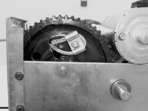
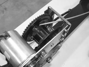
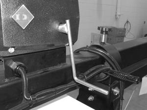
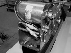
157 LTC Repair Disassembly/Assembly Procedures a b c d e f g wc_gr wc_tx000428gb.fm 157
158 Disassembly/Assembly Procedures 8.12 Replacing Fuel Tank LTC Repair See Graphic: wc_gr Removal: Shut down the engine and disconnect the battery Position the main mast in the vertical position. Note: It is not necessary to raise the tower Remove the screws (a) securing the mast cradle (b) and remove the mast cradle Remove the cable clamp (c) securing the tower power supply cable (d) Using a suitable rope or wire (e), secure the two doors in the open position Remove the four screws (f) securing the enclosure top and using an appropriate hoist or crane, lift the enclosure top from the machine Snip the wire ties (g) Remove the bolts (h) securing the hold-down straps (i) Disconnect the fuel intake (j) and return lines (k) With the aid of a partner or appropriate hoist, lift the fuel tank from the machine. Reassembly: Position the fuel tank into the machine Slide new wire ties (g) underneath the hold-down straps (i) and secure the fuel tank to the machine with the hold-down straps using bolts (h) Reconnect the fuel intake (j) and return lines (k) Using an appropriate hoist or crane, position the enclosure top onto the machine. Secure the enclosure top to the machine with four screws (f) Position the tower power supply cable (d) and secure it to the machine using the cable clamp (c) Remove the rope or wire securing the two doors in the open position Secure the mast cradle (b) to the top enclosure using screws (a). wc_tx000428gb.fm 158

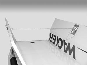
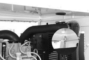
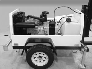
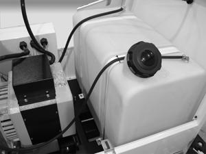
159 LTC Repair Disassembly/Assembly Procedures b a c d e f j i h g k wc_gr wc_tx000428gb.fm 159
 from the hour meter. 8.13.4 Pull out the tabs (b) on the locking bracket (c) and remove the hour meter from the panel.")
160 Disassembly/Assembly Procedures 8.13 Replacing Hour Meter LTC Repair See Graphic: wc_gr Disassembly: Shut down the engine and disconnect the battery Remove the six screws securing the control panel cover to the control panel Make note of the wire connections on the hour meter and remove the wires (a) from the hour meter Pull out the tabs (b) on the locking bracket (c) and remove the hour meter from the panel. Reassembly: Insert the replacement hour meter into the control panel and secure it with the locking bracket (c) Attach the wires (a) to the appropriate terminals of the hour meter Secure the control panel cover to the control panel with the six screws. wc_tx000428gb.fm 160
en 002. Light Tower LTC 4 REPAIR MANUAL
 0163171en 002 1208 Light Tower LTC 4 REPAIR MANUAL 0 1 6 3 1 7 1 E N LTC Repair This manual covers the following machines: Item No. Revisions Covered 0009375 105 and higher 0620017 103 and higher 0620018
en Light Tower LTC 4 REPAIR MANUAL
 www.wackergroup.com 0163722en 001 0910 Light Tower LTC 4 REPAIR MANUAL 0 1 6 3 7 2 2 E N LTC Repair This manual covers the following machines: Item No. Revisions Covered 0009377 105 and higher 0009379
en 006 Light Tower LTC 4L OPERATOR S MANUAL
 www.wackergroup.com 0158137en 006 1205 Light Tower OPERATOR S MANUAL 0 1 5 8 1 3 7 E N Table of Contents 1. Foreword 3 2. Safety Information 4 2.1 Laws Pertaining to Spark Arresters... 4 2.2 Operating
Operator s Manual. Light Tower, Wide Body LTW 6K LTW 8K en
 Operator s Manual Light Tower, Wide Body LTW 6K LTW 8K 0175283en 002 0810 0 1 7 5 2 8 3 E N Copyright notice Copyright 2010 by Wacker Neuson Corporation. All rights, including copying and distribution
GV 2500A GV 3800A GV 5600A GV 6600A
 0171887en 002 0609 Generator GV 2500A GV 3800A GV 5600A GV 6600A REPAIR MANUAL 0 1 7 1 8 8 7 E N GV Generator Repair Foreword Machines covered by this manual Machine Item Number GV 2500A 0620286, 0620542
Portable Lighting Equipment Operating Instructions Table of Contents
 Portable Lighting Equipment Operating Instructions Table of Generac Magnum Ingersoll Rand TEREX AMIDA TEREX GENIE Model: MLT3060 Model: LIGHTSOURCE Model: Amida AL4000 series Model: TML4000N Generac Magnum
en Generator GP 2500A OPERATOR S MANUAL
 0163727en 005 0509 Generator GP 2500A OPERATOR S MANUAL 0 1 6 3 7 2 7 E N DANGER CARBON MONOXIDE Using a generator indoors CAN KILL YOU IN MINUTES. Generator exhaust contains carbon monoxide (CO). This
en 003 Generator GV 5600A OPERATOR S MANUAL
 www.wackergroup.com 0170813en 003 0108 Generator OPERATOR S MANUAL 0 1 7 0 8 1 3 E N DANGER CARBON MONOXIDE Using a generator indoors CAN KILL YOU IN MINUTES. Generator exhaust contains carbon monoxide
en Vibroplate VP 1550 (RAW) OPERATOR S MANUAL
 OPERATOR S MANUAL") www.wackergroup.com 0157759en 001 0703 Vibroplate VP 1550 (RAW) OPERATOR S MANUAL 0 1 5 7 7 5 9 E N VP 1550 (RAW) Table of Contents 1. Foreword 2 2. Safety Information 3 2.1 Laws Pertaining to Spark Arresters...
www.wackergroup.com 0157759en 001 0703 Vibroplate VP 1550 (RAW) OPERATOR S MANUAL 0 1 5 7 7 5 9 E N VP 1550 (RAW) Table of Contents 1. Foreword 2 2. Safety Information 3 2.1 Laws Pertaining to Spark Arresters...
G 2.5A G 3.7A G 5.6A GS 5.6A GS 8.5V GS 9.7V
 www.wackergroup.com 0112013 004 1002 en Portable Generators G 2.5A G 3.7A G 5.6A GS 5.6A GS 8.5V GS 9.7V REPAIR MANUAL 0 1 1 2 0 1 3 Portable Generator Repair Foreword This manual covers machines with
PORTABLE TRASH PUMPS MDP200
 PORTABLE TRASH PUMPS MDP200 OPERATING & PARTS MANUAL INTRODUCTION This manual provides information and procedures to safely operate and maintain the engine and pump. For your own safety and protection
Repair Manual. Roller RD 12
 Repair Manual Roller RD 12 EN 5000192242 02 0912 5 0 0 0 1 9 2 2 4 2 Copyright notice Copyright 2012 by Wacker Neuson Production Americas LLC All rights, including copying and distribution rights, are
PORTABLE TRASH PUMPS MTP200 MTP300 MTP400
 PORTABLE TRASH PUMPS MTP200 MTP300 MTP400 OPERATING & PARTS MANUAL INTRODUCTION This manual provides information and procedures to safely operate and maintain the engine and pump. For your own safety and
Operator s Manual. Inverter Generator. GPi en
 Operator s Manual Inverter Generator GPi 1700 0179739en 002 0311 0 1 7 9 7 3 9 E N Copyright notice Copyright 2010 by Wacker Neuson Corporation. All rights, including copying and distribution rights, are
Voltmaster Centrifugal Trash Pumps
 Voltmaster Centrifugal Trash Pumps Model TSP2, TSP3 and TSP4 Owner s Manual February 2011 Table of Contents 1 Introduction............................ 1 1.1 Read before using..................... 1 1.2
en Generator, Non-CARB GPS 8500 GPS 9700 OPERATOR S MANUAL
 0176674en 002 0809 Generator, Non-CARB GPS 8500 GPS 9700 OPERATOR S MANUAL 0 1 7 6 6 7 4 E N DANGER CARBON MONOXIDE Using a generator indoors CAN KILL YOU IN MINUTES. Generator exhaust contains carbon
Repair Manual. Rammer BS 50 / BS 60 / BS 70 BS 500 / BS 600 / BS 700 BS 65 / BS 650 DS 70 / DS 720
 Repair Manual Rammer BS 50 / BS 60 / BS 70 BS 500 / BS 600 / BS 700 BS 65 / BS 650 DS 70 / DS 720 EN 5000114549 11 0411 5 0 0 0 1 1 4 5 4 9 Copyright notice Copyright 2011 by Wacker Neuson Corporation.
en Backpack Vibrator BV 35A-P BV 50A-P OPERATOR S MANUAL
 0171881en 003 0708 Backpack Vibrator BV 35A-P BV 50A-P OPERATOR S MANUAL 0 1 7 1 8 8 1 E N BV Table of Contents 1. Foreword 5 2. Safety Information 6 2.1 Laws Pertaining to Spark Arresters... 6 2.2 Operating
Operator s Manual. Inverter Generator. GPi 1700
 Operator s Manual Inverter Generator GPi 1700 EN 5000186370 05 0813 5 0 0 0 1 8 6 3 7 0 Copyright notice Copyright 2013 by Wacker Neuson Production Americas LLC All rights, including copying and distribution
MAXI-LITE V-SERIES ML 7.5/ML 8 OPERATOR S MANUAL ALLMAND BROS. INC P.O. BOX 888 HOLDREGE, NE 68949
 MAXI-LITE V-SERIES ML 7.5/ML 8 OPERATOR S MANUAL ALLMAND BROS. INC P.O. BOX 888 HOLDREGE, NE 68949 PHONE: 308/995-4495, 1-800/562-1373 ALLMAND FAX: 308/995-5887 ALLMAND PARTS FAX: 308/995-4883 MAXI-LITE
Repair Manual. Mobile Generator G en
 Repair Manual Mobile Generator G 70 0175252en 004 0709 0 1 7 5 2 5 2 E N Copyright notice Copyright 2009 by Wacker Neuson Corporation. All rights, including copying and distribution rights, are reserved.
Table of Contents. Safety symbols... 3 Assembly 6. Operation Maintenance Troubleshooting 11. Storage. 12. Notes. 13
 Table of Contents Safety symbols... 3 Assembly 6 Operation... 8 Maintenance... 10 Troubleshooting 11 Storage. 12 Notes. 13 2 Safety Information Attention; this machine can be dangerous! All operators should
Propane torch. Model Assembly And Operation Instructions
 Propane torch Model 39953 Assembly And Operation Instructions Due to continuing improvements, actual product may differ slightly from the product described herein. 3491 Mission Oaks Blvd., Camarillo, CA
GP 6600A GPS 6600A CARB
 0171950en 002 0609 Generator GP 6600A GPS 6600A CARB OPERATOR S MANUAL 0 1 7 1 9 5 0 E N DANGER CARBON MONOXIDE Using a generator indoors CAN KILL YOU IN MINUTES. Generator exhaust contains carbon monoxide
SP6. Automatic Battery Charger. Model
 Model SP6 Automatic Battery Charger OWNERS MANUAL PLEASE SAVE THIS OWNERS MANUAL AND READ BEFORE EACH USE. This manual will explain how to use the charger safely and effectively. Please read and follow
Log Splitter. Owner/Operator Manual. Models HCWP1-26
 Log Splitter Owner/Operator Manual Models HCWP1-26 SAFETY..........................2 SAFETY WARNING SYMBOL.........3 SAFETY RULES.................. 4-5 SPECIFICATIONS................. 6 CONTROLS AND FEATURES.......
en Generator GP 5600A GPS 5600A OPERATOR S MANUAL
 0163127en 005 1007 Generator GP 5600A GPS 5600A OPERATOR S MANUAL 0 1 6 3 1 2 7 E N DANGER CARBON MONOXIDE Using a generator indoors CAN KILL YOU IN MINUTES. Generator exhaust contains carbon monoxide
en Trench Roller RT 56SC-2 RT 82SC-2 OPERATOR S MANUAL
 0170875en 004 1109 Trench Roller RT 56SC-2 RT 82SC-2 OPERATOR S MANUAL 0 1 7 0 8 7 5 E N Table of Contents 1 Safety Information 7 1.1 Laws Pertaining to Spark Arresters... 7 1.2 Operating Safety... 8
Operator s Manual. Ride-On Roller RD en
 Operator s Manual Ride-On Roller RD 16 0178395en 005 0310 0 1 7 8 3 9 5 E N Copyright notice Copyright 2010 by Wacker Neuson Corporation. All rights, including copying and distribution rights, are reserved.
MAXI-LITE HYDRAULIC TOWER 683, 695, 883, 895, and 895XL OPERATOR S MANUAL ALLMAND BROS. INC P.O. BOX 888 HOLDREGE, NE 68949
 MAXI-LITE HYDRAULIC TOWER 683, 695, 883, 895, and 895XL OPERATOR S MANUAL ALLMAND BROS. INC P.O. BOX 888 HOLDREGE, NE 68949 PHONE: 308/995-4495, 1-800/562-1373 ALLMAND FAX: 308/995-5887 ALLMAND PARTS FAX:
CONTENTS: 5740AH - 40 Ton Air/Hydraulic Shop Press 5750AH - 50 Ton Air/Hydraulic Shop Press OWNER'S MANUAL
 OWNER'S MANUAL CONTENTS: Page 1 Specifications 2 Safety Information and Warranty Information 3 Parts List 4-6 Assembly Instructions 7 Pump and Ram Assembly Instructions 8 Procedure for Bleeding Air 9 Pump
NIGHT LITE PRO II OPERATOR S MANUAL
 REVISED AUGUST 2011 NIGHT LITE PRO II OPERATOR S MANUAL ALLMAND BROTHERS INC. P.O. BOX 888 HOLDREGE, NE 68949 PHONE: (308) 995-4495, 1-800- 562-1373 ALLMAND FAX: (308) 995 5887 ALLMAND PARTS DEPT. FAX
en Mobile Generator G 150 G 180 G 240 OPERATOR S MANUAL
 0171953en 003 0709 Mobile Generator G 150 G 180 G 240 OPERATOR S MANUAL 0 1 7 1 9 5 3 E N G 150 / 180 / 240 Foreword Foreword Machine Documentation Keep a copy of the Operator s Manual with the machine
4000 SYSTEM OPERATING MANUAL
 4000 SYSTEM OPERATING MANUAL REV 1.4 COPYRIGHT 1996 Xenotech, Inc. PAGE 1 INSTRUCTIONS FOR REMOVING AND INSTALLING A TYPE XT XENON BULB IN A BL4000 FIXTURE NOTE FAMILIARIZE YOURSELF WITH THE LOCATION AND
en Walk-Behind Trowels CT 36 CT 48 REPAIR MANUAL
 www.wackergroup.com 0163091en 003 1007 Walk-Behind Trowels CT 36 CT 48 REPAIR MANUAL 0 1 6 3 0 9 1 E N CT Repair Foreword This manual covers machines with Item Number: 0009438, 0009439, 0009442, 0009443,
en Hydronic Surface Heater S 3000 REPAIR MANUAL
 0178388en 002 0209 Hydronic Surface Heater S 3000 REPAIR MANUAL 0 1 7 8 3 8 8 E N S 3000 Repair Foreword Foreword Machines covered by this manual Machine Item Number S 3000 0620182 S 3000 0620218 Machine
Important. Contents. Contact us:
 Operator's Manual Second Edition First Printing Important Read, understand and obey these safety rules and operating instructions before operating this machine. Only trained and authorized personnel shall
1100W PORTABLE GENERATOR
 1100W PORTABLE GENERATOR MODEL NO: G1200 PART NO: 8010110 OPERATION & MAINTENANCE INSTRUCTIONS LS0312 INTRODUCTION Thank you for purchasing this CLARKE 1100W Portable Generator. Before attempting to use
Technical Publications AWP. Operator's Manual. Fourth Edition, First Printing Part No
 Technical Publications AWP Operator's Manual Fourth Edition, First Printing Part No. 424 Operator s Manual Fourth Edition Important Read, understand and obey these safety rules and operating instructions
BL7000 SYSTEM OPERATING MANUAL
 BL7000 SYSTEM OPERATING MANUAL REV 2.0 208 / 230V COPYRIGHT 1995 Xenotech, Inc. PAGE 1 POWER INPUT CONNECTOR WIRING INSTRUCTIONS THE INPUT POWER REQUIREMENTS FOR A 7 KW POWER SUPPLY ARE AS FOLLOWS. VOLTAGE
PROPANE TORCH WITH TURBO BURNER
 PROPANE TORCH WITH TURBO BURNER MODEL 91894 ASSEMBLY AND OPERATING INSTRUCTIONS 3491 Mission Oaks Blvd., Camarillo, CA 93011 Visit our Web site at http://www.harborfreight.com TO PREVENT SERIOUS INJURY,
C.fm Page 1 Thursday, February 21, :28 AM Raptor user manual
 Raptor user manual 1 mounting bracket 2 swivel lock 3 clamp hole 4 lamp access screws 5 air vents 6 AC input & main fuse 7 cooling fan Thank you for selecting the Martin Raptor. This Martin lighting fixture
PRO6.4, PRO6.4E, PRO9.0, PRO9.0E Generator Service Manual
 PRO6.4, PRO6.4E, PRO9.0, PRO9.0E Generator Service Manual IMPORTANT: Read all safety precautions and instructions carefully before operating equipment. Ensure equipment is stopped and level before performing
Important. Contents. Contact us:
 Operator's Manual Third Edition Third Printing Important Read, understand and obey these safety rules and operating instructions before operating this machine. Only trained and authorized personnel shall
en Pump PS PS OPERATOR S MANUAL
 0154622en 002 0107 Pump PS 3 1500 PS 3 2200 OPERATOR S MANUAL 0 1 5 4 6 2 2 E N PS 3 1500/ PS 3 2200 Table of Contents 1. Foreword 3 2. Safety Information 4 2.1 Operating and Electrical Safety... 5 2.2
en Pump PTS 4V PTK 4 REPAIR MANUALS
 www.wackergroup.com 0163209en 001 0207 Pump PTS 4V PTK 4 REPAIR MANUALS 0 1 6 3 2 0 9 E N PT 4 Repair Foreword This manual covers machines with Item Number: 0007683, 0007691, 0007692 Operating / Parts
Models: SP3, SPSS3 Automatic Battery Charger
 OWNERS MANUAL Models: SP3, SPSS3 Automatic Battery Charger PLEASE SAVE THIS OWNERS MANUAL AND READ BEFORE EACH USE. This manual will explain how to use the charger safely and effectively. Please read and
D.fm Page 1 Wednesday, March 5, :21 PM Raptor user manual
 Raptor user manual 1 mounting bracket 2 swivel lock 3 clamp hole 4 lamp access screws 5 air vents 2001-2002 Martin Professional A/S, Denmark. All rights reserved. No part of this manual may be reproduced,
OPERATION MANUAL MODELS TWE-250 TWE-321 TWE-375 TRU WELD EQUIPMENT COMPANY 6400 N. HONEYTOWN ROAD SMITHVILLE, OHIO (330)
") OPERATION MANUAL MODELS TWE-250 TWE-321 TWE-375 TRU WELD EQUIPMENT COMPANY 6400 N. HONEYTOWN ROAD SMITHVILLE, OHIO 44677 (330) 669 2773 CONTENTS Section Description Pages 1 Introduction 3 2 External Features
OPERATION MANUAL MODELS TWE-250 TWE-321 TWE-375 TRU WELD EQUIPMENT COMPANY 6400 N. HONEYTOWN ROAD SMITHVILLE, OHIO 44677 (330) 669 2773 CONTENTS Section Description Pages 1 Introduction 3 2 External Features
Gasoline Inverter Generator
 user manual Gasoline Inverter Generator table of contents Preface Introduction... Safety Information Exhaust fumes are poisonous... Fuel is highly flammable and poisonous... Engine and muffler may be hot...
Swing Arm Magnifying Lamp
 Owner s Manual & Safety Instructions Save This Manual Keep this manual for the safety warnings and precautions, assembly, operating, inspection, maintenance and cleaning procedures. Write the product s
Passenger Stair / Crewstair
 Ground Support Equipment April, 204 Revision (0) Date Passenger Stair / Crewstair (A227266D) Operation & Maintenance Manual WASP, Inc. PRINTED IN THE U.S.A. Model A227266D TABLE OF CONTENTS TABLE OF CONTENTS
Important. Contents. Contact us:
 Operator's Manual First Edition Ninth Printing Important Read, understand and obey these safety rules and operating instructions before operating this machine. Only trained and authorized personnel shall
Wind and Temperature Tip Over Hazard Do not add notice boards or similar
 Lift & Work Platform Safety Information Safety Information: Boom Lifts Safety Information: Scissor Lifts Safety Information: Boom Lifts Power Lines Electrocution Hazard Maintain safe clearance from Electrical
1200W INVERTER GENERATOR
 1200W INVERTER GENERATOR MODEL NO: IG1200 PART NO: 8877070 OPERATION & MAINTENANCE INSTRUCTIONS LS0117 INTRODUCTION Thank you for purchasing this CLARKE 1200W Inverter Generator. Before attempting to use
POW R Lite Kit for Towable Generators
 POW R Lite Kit for Towable Generators TS25 through TS80 Installation & Operating Manual 9/09 MN2421 Any trademarks used in this manual are the property of their respective owners. WARNING: CALIFORNIA PROPOSITION
Models 8100PP & 86110LP. Installation Instructions CAUTION. Read this document before installing the snowplow. CAUTION
 September 15, 2010 Lit. No. 48645, Rev. 02 POWER PLOW Snowplows Models 8100PP & 86110LP Installation Instructions Read this document before installing the snowplow. See your BLIZZARD outlet/web site for
User Guide IGD Series
 US User Guide IGD Series DANGER PRIOR TO USE, READ AND UNDERSTAND PRODUCT SAFETY INFORMATION. Failure to follow the instructions may result in ELECTRICAL SHOCK, EXPLOSION, or FIRE, which may result in
ECSS. Electric Chain Saw Chain Sharpener Assembly & Operating Instructions
 ECSS Electric Chain Saw Chain Sharpener Assembly & Operating Instructions READ ALL INSTRUCTIONS AND WARNINGS BEFORE USING THIS PRODUCT. SAVE THESE INSTRUCTIONS FOR FUTURE REFERENCE. This manual provides
CONTENTS: SPECIFICATIONS 5712BT - 12 TON BENCH TOP HYDRAULIC SHOP PRESS OWNER'S MANUAL
 OWNER'S MANUAL CONTENTS: Page 1 Specifications 2 Warning Information 3 Assembly and Operating Instructions 4 Preventative Maintenance and Warranty Information 5 Exploded View Drawing and Parts List SPECIFICATIONS
6330 AND 8330 OPERATOR S MANUAL ALLMAND BROS. INC P.O. BOX 888 HOLDREGE, NE 68949
 NIGHT-LITE 6330 AND 8330 OPERATOR S MANUAL ALLMAND BROS. INC P.O. BOX 888 HOLDREGE, NE 68949 PHONE: 308/995-4495, 1-800/562-1373 ALLMAND FAX: 308/995-5887 ALLMAND PARTS FAX: 308/995-4883 NIGHT- LITE SERIES
4.2 Component Identification
 Digital Control Panels Deep Sea Electronics 5220 4.1 General 4.2 Component Identification 4.3 The YML5220 Controller 4.4 Description of Controls 4.5 Navigation 4.5.1 General Navigation 4.5.2 The Event
Operator Manual. This operator manual has. information for all models. of series M plus some. options and accessories. Some of the illustrations
 M S E R I E Operator Manual S This operator manual has information for all models of series M plus some options and accessories. Some of the illustrations and information may not The most apply to your
Towable Generators and Light Tower
 Towable Generators and Light Tower (Diesel Liquid Cooled) TG8LT TG10T, 15T, 20T and 25T Installation & Operating Manual 8/12 MN2423 Any trademarks used in this manual are the property of their respective
NILFISK BA 500 Service Manual
 NILFISK BA 500 Service Manual Model 66324400 12/94 Form Number 043023 TABLE OF CONTENTS Batteries...21 Brush Drive Belt Adjustment Or Replacement...7 Brush Drive Motor - Carbon brush Inspection... 8 Brush
CONTENTS: Ton Hydraulic Shop Press w/ Winch Ton Hydraulic Shop Press w/ Winch OWNER'S MANUAL
 OWNER'S MANUAL CONTENTS: Page 1 Specifications 2 Safety Information and Warranty Information 3 Parts List 4-8 Assembly Instructions 9 Procedure for Bleeding Air 10 Pump Instructions 11-12 Winch Kit List
Table of Contents. Safety symbols... 3 Assembly 6. Hydraulic oil Towing safety. 12 Pre-operation / Starting Operation Guidelines.
 Table of Contents Safety symbols... 3 Assembly 6 Hydraulic oil.. 11 Towing safety. 12 Pre-operation / Starting.. 13 Operation Guidelines. 14 Operation 16 Maintenance... 18 Storage... 19 Troubleshooting.
OPERATION MANUAL MODELS TWE-250 TWE-321 TWE-375 TRU WELD EQUIPMENT COMPANY 6400 N. HONEYTOWN ROAD SMITHVILLE, OHIO (330)
") OPERATION MANUAL MODELS TWE-250 TWE-321 TWE-375 TRU WELD EQUIPMENT COMPANY 6400 N. HONEYTOWN ROAD SMITHVILLE, OHIO 44677 (330) 669 2773 Version 1.3 Date 10/20/2010 TRU WELD EQUIPMENT LIMITED WARRANTY All
OPERATION MANUAL MODELS TWE-250 TWE-321 TWE-375 TRU WELD EQUIPMENT COMPANY 6400 N. HONEYTOWN ROAD SMITHVILLE, OHIO 44677 (330) 669 2773 Version 1.3 Date 10/20/2010 TRU WELD EQUIPMENT LIMITED WARRANTY All
610 BUSHEL MANURE SPREADER
 610 BUSHEL MANURE SPREADER RODA MANUFACTURING 1008 LOCUST ST. HULL, IA. 51239 Art s-way Manufacturing 712-439-2366 Co., Inc. Hwy 9 West - PO Box 288 WWW.RODAMFG.COM Armstrong, IA. 50514 U.S.A 2 INTRODUCTION
PW Operator Manual PW This operator manual. has information for all. models of series PW plus some options. and accessories.
 Operator Manual PW 3000 S E R I E S This operator manual has information for all models of series PW 3000 plus some options and accessories. Some The most of the illustrations and important component information
Low Profile Tailgate Spreaders SWING AWAY Mount
 August 1, 2018 Lit. No. 43269, Rev. 02 Low Profile Tailgate Spreaders SWING AWAY Mount Not for Use on Ford F-250/350/450 2017 Installation Instructions Read this document before installing or operating
en 002 Engine WM 130 WM 170 WM 270 OPERATOR S MANUAL
 www.wackergroup.com 0156647en 002 0405 Engine WM 130 WM 170 WM 270 OPERATOR S MANUAL 0 1 5 6 6 4 7 E N WM 130/170/270 Table of Contents 1. Foreword 2 2. Emission Control System Information 3 3. Safety
Operator s Manual. Flameless Air Heater HIF 690
 Operator s Manual Flameless Air Heater HIF 690 EN 5200013292 02 0813 5 2 0 0 0 1 3 2 9 2 Copyright notice Copyright 2013 by Wacker Neuson Production Americas LLC All rights, including copying and distribution
JOHN DEERE WORLDWIDE COMMERCIAL & CONSUMER EQUIPMENT DIVISION. Lawn Tractors L100, L110, L120, and L130 TM2026 DECEMBER 2002 TECHNICAL MANUAL
 2026 December 2002 JOHN DEERE WORLDWIDE COMMERCIAL & CONSUMER EQUIPMENT DIVISION Lawn Tractors L100, L110, L120, and L130 TM2026 DECEMBER 2002 TECHNICAL MANUAL North American Version Litho in U.S.A. Safety
Provided by: Operating, Maintenance & Parts Manual
 Provided by: www.hoistsdirect.com TB681.qxd 11/29/2004 3:04 PM Page 1 Operating, Maintenance & Parts Manual TB603 Manually Lever Operated Chain Hoist 1100 POUNDS MAXIMUM CAPACITY (500 kg) Follow all instructions
HORTICULTURE EQUIPMENT & SERVICES
 HORTICULTURE EQUIPMENT & SERVICES OPERATOR S MANUAL PEAT BALE PROCESSOR Model Number: LH00 Serial Number: 30000 & UP Contents Introduction Page Safety Safety 2 Safety Decal Instructions 2 Specifications
INSTALLATION INSTRUCTIONS
 INSTALLATION INSTRUCTIONS WARNING: NEVER EXCEED YOUR VEHICLE MANUFACTURER'S RECOMMENDED TOWING CAPACITY A20 5TH WHEEL HITCH TABLE OF CONTENTS Page# Description 1 Warnings & Precautions 2 - Assembly & Installation
Owner s Manual & Safety Instructions
 Owner s Manual & Safety Instructions Save Save This This Manual Keep Keep this this manual manual for for the the safety safety warnings warnings and and precautions, assembly, assembly, operating, inspection,
75918 Heavy Duty 3-Point Mount
 December 15, 2015 Lit. No. 75581, Rev. 00 75918 Heavy Duty 3-Point Mount Installation Instructions Read Owner's Manual before operating or servicing spreader. A DIVISION OF DOUGLAS DYNAMICS, LLC SAFETY
PNEUMATIC SLIDING VALVE
 INSTALLATION, OPERATION, & #: MM-SV001 6-23-09 Rev. A Page 1 of 8 PNEUMATIC SLIDING VALVE PART NUMBERS (Including, but not inclusive) SV704MSTS, SV714MSTS, SV754MSTS, SV764MSTS, SV774MSTS, SV706MSTS, SV716MSTS,
Make/Type/Size/Model Honda Generator EB 3500X & EB5000X Operators Manual Open Well Ventilated Area to Start & Shut Down Machine
 HONDA GENERATORS ARE DESIGNED TO GIVE SAFE AND DEPENDABLE SERVICE IF OPERATED ACCORDING TO INSTRUCTIONS. YOU CAN HELP PREVENT ACCIDENTS BY BEING FAMILIAR WITH YOUR GENERATORS CONTROLS AND BY OBSERVING
MODEL HD99 HYDRAULIC ONE MAN TOWABLE EARTHDRILL
 DO NOT THROW AWAY IMPORTANT MANUAL MODEL HD99 HYDRAULIC ONE MAN TOWABLE EARTHDRILL Operators Manual GROUND HOG, INC. P.O.BOX 290 San Bernardino, CA. 92402 Phone (909) 478-5700 Fax (909) 478-5710 E-mail:
DWHOIST. Drywall Hoist Assembly & Operating Instructions
 DWHOIST Drywall Hoist Assembly & Operating Instructions READ ALL INSTRUCTIONS AND WARNINGS BEFORE USING THIS PRODUCT. SAVE THESE INSTRUCTIONS FOR FUTURE REFERENCE. This manual provides important information
Model: PI-140 Power Inverter Converts 12V DC battery power to 120V AC household power
 OWNER S MANUAL Model: PI-140 Power Inverter Converts 12V DC battery power to 120V AC household power READ THE ENTIRE MANUAL BEFORE USING THIS PRODUCT. FAILURE TO DO SO COULD RESULT IN SERIOUS INJURY OR
Airless Spray Gun INSTRUCTIONS DP psi (345 bar) Maximum Working Pressure
 Maximum Working Pressure") INSTRUCTIONS DP-6376 Airless Spray Gun 5000 psi (345 bar) Maximum Working Pressure INSTRUCTIONS This manual contains important warnings and information. READ AND KEEP FOR REFERENCE. Table of Contents Warnings......................................
INSTRUCTIONS DP-6376 Airless Spray Gun 5000 psi (345 bar) Maximum Working Pressure INSTRUCTIONS This manual contains important warnings and information. READ AND KEEP FOR REFERENCE. Table of Contents Warnings......................................
Operating and Assembly Manual
 Model 1080 Operating and Assembly Manual Midwest Equipment Manufacturing, Inc. 5225 Serum Plant Road Thorntown, IN 46071 08-02-16 SAFETY RULES Remember, any power equipment can cause injury if operated
EJ212 Electric Jack 1 Ton (2,000 lbs) Assembly & Operating Instructions
 Assembly & Operating Instructions") EJ212 Electric Jack 1 Ton (2,000 lbs) Assembly & Operating Instructions READ ALL INSTRUCTIONS AND WARNINGS BEFORE USING THIS PRODUCT. This manual provides important information on proper operation & maintenance.
EJ212 Electric Jack 1 Ton (2,000 lbs) Assembly & Operating Instructions READ ALL INSTRUCTIONS AND WARNINGS BEFORE USING THIS PRODUCT. This manual provides important information on proper operation & maintenance.
MAXI-LITE AS3000 AUSTRALIAN STANDARD OPERATOR S MANUAL ALLMAND BROTHERS INC. P.O. BOX 888 HOLDREGE, NE PHONE: (308) ,
 ,") MAXI-LITE AS3000 AUSTRALIAN STANDARD OPERATOR S MANUAL ALLMAND BROTHERS INC. P.O. BOX 888 HOLDREGE, NE 68949 PHONE: (308) 995-4495, 1-800- 562-1373 ALLMAND FAX: (308) 995 5887 ALLMAND PARTS DEPT. FAX :
MAXI-LITE AS3000 AUSTRALIAN STANDARD OPERATOR S MANUAL ALLMAND BROTHERS INC. P.O. BOX 888 HOLDREGE, NE 68949 PHONE: (308) 995-4495, 1-800- 562-1373 ALLMAND FAX: (308) 995 5887 ALLMAND PARTS DEPT. FAX :
ACCUSENSE CHARGE SERIES ON/OFF BOARD FULLY AUTOMATIC BATTERY CHARGER
 ACCUSENSE CHARGE SERIES ON/OFF BOARD FULLY AUTOMATIC BATTERY CHARGER SPECIFICATIONS: *Photo for reference only* Part number 8890439 Mode Select: Selects Battery Type Refer to Section 6. IMPORTANT: READ
Stainless Steel Rotary Drum Pump
 Please read and save this Repair Parts Manual. Read this manual and the General Operating Instructions carefully before attempting to assemble, install, operate or maintain the product described. Protect
CONTENTS: 5740AH - 40 Ton Air/Hydraulic Shop Press 5750AH - 50 Ton Air/Hydraulic Shop Press OWNER'S MANUAL
 OWNER'S MANUAL CONTENTS: Page 1 Specifications 2 Safety Information and Warranty Information 3 Parts List 4-6 Assembly Instructions 7 Pump and Ram Assembly Instructions 8 Procedure for Bleeding Air 9 Pump
6,000 Watt Generator - Water Cooled Diesel Engine - 25' Telescoping Tower - (4) 500W LED Fixtures
 500W LED Fixtures") 6,000 Watt Generator - Water Cooled Diesel Engine - 25' Telescoping Tower - (4) 500W LED Fixtures Part #: WCDE-4-4X400LTL-LED Page: 1 Made in Texas The WCDE-4-MHL mobile light tower from Larson Electronics
6,000 Watt Generator - Water Cooled Diesel Engine - 25' Telescoping Tower - (4) 500W LED Fixtures Part #: WCDE-4-4X400LTL-LED Page: 1 Made in Texas The WCDE-4-MHL mobile light tower from Larson Electronics
LDG6000SA DIESEL GENERATOR OWNERS MANUAL
 LDG6000SA DIESEL GENERATOR OWNERS MANUAL BEFORE OPERATING THIS EQUIPMENT PLEASE READ THESE INSTRUCTIONS CAREFULLY Preface Thank-you for purchasing this generator. This operation manual contains information
60V RECHARGEABLE LITHIUM-ION BATTERY
 60V RECHARGEABLE LITHIUM-ION BATTERY LB60A00/LB60A03/LB60A01/LB60A02 Owner s Manual TOLL-FREE HELPLINE: 1-855-345-3934 www.greenworkstools.com Read all safety rules and instructions carefully before operating
8100PP & 86110LP POWER PLOW Snowplows
 April 1, 2010 Lit. No. 40690, Rev. 02 8100PP & 86110LP POWER PLOW Snowplows Installation Instructions Read this document before installing the snowplow. See your BLIZZARD outlet/web site for specific vehicle
Measurements are expressed in millimeters.
 T-Rex user manual Measurements are expressed in millimeters. 1 Lamp access 2 Focus adjustment 3 Mounting bracket 4 Swivel locks 5 Clamp hole 6 Air vent 190 285 7 AC input & main fuse 8 Microphone 490 164
Parallel Lift Rack MODEL RM
 Form 4401T, 09-03 Supersedes Form 4401T, 10-00 OPERATION INSTRUCTIONS Parallel Lift Rack MODEL RM Copyright 1998-2003 Hunter Engineering Company Contents 1. For Your Safety... 1 1.1 Warning/Instruction
TJ lb Capacity Trailer Jack. 2-in-1 Combo With Swing Back Design. Assembly & Operating Instructions
 TJ1500 1500 lb Capacity Trailer Jack 2-in-1 Combo With Swing Back Design Assembly & Operating Instructions READ ALL INSTRUCTIONS AND WARNINGS BEFORE USING THIS PRODUCT. This manual provides important information
Smart-Till. Models ST101, ST151, ST203, and ST303. HCC, inc st Avenue Mendota, IL
 Owners Manual Smart-Till Models ST101, ST151, ST203, and ST303 HCC, inc. 1501 1st Avenue Mendota, IL 61342 815-539-9371 www.hccincorporated.com C-1159 May 2010 Safety Most work related accidents are caused
Model: SPTOGT01 TRACTOR PTO GENERATOR
 www.scintex.com.au sales@scintex.com.au Model: SPTOGT01 TRACTOR PTO GENERATOR SET UP, OPERATING, AND SERVICING INSTRUCTIONS Read this material before using this product. Failure to do so can result in