Repair Manual. Rammer BS 50 / BS 60 / BS 70 BS 500 / BS 600 / BS 700 BS 65 / BS 650 DS 70 / DS 720
|
|
|
- Charla Bradley
- 5 years ago
- Views:
Transcription

1 Repair Manual Rammer BS 50 / BS 60 / BS 70 BS 500 / BS 600 / BS 700 BS 65 / BS 650 DS 70 / DS 720 EN
2 Copyright notice Copyright 2011 by Wacker Neuson Corporation. All rights, including copying and distribution rights, are reserved. This publication may be photocopied by the original purchaser of the machine. Any other type of reproduction is prohibited without express written permission from Wacker Neuson Corporation. Any type of reproduction or distribution not authorized by Wacker Neuson Corporation represents an infringement of valid copyrights. Violators will be prosecuted. Trademarks All trademarks referenced in this manual are the property of their respective owners. Manufacturer Wacker Neuson Corporation N92W15000 Anthony Avenue Menomonee Falls, WI U.S.A. Tel: (262) Fax: (262) Tel: (800)
3 Rammer Repair Foreword Foreword Machines covered in this manual. BS , , , , , , , BS , , , , , , , , , , , , , BS 50-2i , , , , , , , , BS , , , , , BS BS 500-oi , BS 500S BS , , , , , , , , , , , , , , , BS , , , , , BS 60-2i , , , , , BS , , , , , BS BS 600-oi , BS 600S BS , , , , BS 70-2i , , , BS , , , , , , BS 700-oi , BS 65-V , BS DS , , , , , , , Machine documentation Keep a copy of the Operator s Manual with the machine at all times. Use the separate Parts Book supplied with the machine to order replacement parts. If you are missing any of these documents, please contact Wacker Neuson Corporation to order a replacement or visit When ordering parts or requesting service information, be prepared to provide the machine model number, item number, revision number, and serial number. wc_tx001543gb.fm 3
4 Foreword Expectations for information in this manual Rammer Repair This manual provides information and procedures to safely operate and maintain the above Wacker Neuson model(s). For your own safety and to reduce the risk of injury, carefully read, understand, and observe all instructions described in this manual. Wacker Neuson expressly reserves the right to make technical modifications, even without notice, which improve the performance or safety standards of its machines. The information contained in this manual is based on machines manufactured up until the time of publication. Wacker Neuson reserves the right to change any portion of this information without notice. CALIFORNIA Proposition 65 Warning Engine exhaust, some of its constituents, and certain vehicle components, contain or emit chemicals known to the State of California to cause cancer and birth defects or other reproductive harm. Laws pertaining to spark arresters NOTICE: State Health Safety Codes and Public Resources Codes specify that in certain locations spark arresters be used on internal combustion engines that use hydrocarbon fuels. A spark arrester is a device designed to prevent accidental discharge of sparks or flames from the engine exhaust. Spark arresters are qualified and rated by the United States Forest Service for this purpose. In order to comply with local laws regarding spark arresters, consult the engine distributor or the local Health and Safety Administrator. Manufacturer s approval This manual contains references to approved parts, attachments, and modifications. The following definitions apply: Approved parts or attachments are those either manufactured or provided by Wacker Neuson. Approved modifications are those performed by an authorized Wacker Neuson service center according to written instructions published by Wacker Neuson. Unapproved parts, attachments, and modifications are those that do not meet the approved criteria. Unapproved parts, attachments, or modifications may have the following consequences: Serious injury hazards to the operator and persons in the work area Permanent damage to the machine which will not be covered under warranty Contact your Wacker Neuson dealer immediately if you have questions about approved or unapproved parts, attachments, or modifications. 4 wc_tx001543gb.fm
5 Rammer Repair Table of Contents Foreword 3 1 Safety Information Signal Words Used in this Manual Machine Description and Intended Use Safety Guidelines for Operating the Machine Operator Safety while Using Internal Combustion Engines Service Safety Service and Repair Safety Tools Recommended Special Tools Recommended Repair Tools Maintenance Schedules Periodic Maintenance Schedule (BS 50/60/70-2, BS 65) Periodic Maintenance Schedule (BS 500/600/700/650) Periodic Maintenance Schedule (BS 50/60/70-2i) Periodic Maintenance Schedule (BS 500/600/700-oi) Periodic Maintenance Schedule (DS 70) Periodic Maintenance Schedule (DS 720) Engine and Upper Machine Components Removing the Silencing Cover Replacing the Throttle Control (2-stroke models, 2010 and later) Replacing the Throttle Control ( stroke models) Throttle Control (pre-2010 models) Replacing the Stop Switch (2-stroke models, 2010 and later) Replacing the Stop Switch (4-stroke models, 2010 and later) Replacing the Guide Handle (2-stroke models, 2010 and later) Replacing the Guide Handle (4-stroke models, 2010 and later) Replacing the Guide Handle (pre-2010 models) wc_br en_11toc.fm 5
6 Table of Contents Rammmer Repair 4.10 Shock Mounts Tillotson Carburetor (BS 500/600/700/650 only) Fuel Lines (BS 50/60/70-2, BS 65) Fuel Tank (BS Models) Fuel Tank (DS Models) Fuel Tank Cap Muffler (pre-2009 BS Models) Engine Cooling Fins Muffler (DS Models) Replacing the Walbro Carburetor (auto-release choke models) Replacing the WM 80 Engine (2010 and later models) Removing Walbro Carburetor (standard choke models) Replacing the WM 80 Engine (pre-2010 models) Replacing the Carburetor (WM 100 Engines) Replacing the WM 100 Engine Removing the WM 90 Engine Engine (DS Models) Clutch (2- and 4-stroke models) Clutch (DS 720 only) Clutch (DS 70 only) Ramming System Bellows Replacing the Ramming Shoe Spring System Cover Removal and Installation Spring System Inspecting the Spring System Protective Pipe Ramming System Lubrication (BS 500/600/700/650, DS 720) Ramming System Lubrication (BS 50/60/70, BS 65, DS 70) Crankcase Crank Gear and Connecting Rod Crank Gear, Connecting Rod, and Adjuster Assembly (BS 650/65 only) Clutch Drum wc_br en_11toc.fm
7 Rammer Repair Table of Contents 7 Oil Injection (if equipped) Testing the Float Switch (2010 and later models) Replacing the Float Switch (2010 and later models) Float Switch Testing and Replacement (pre-2010 models) Oil Line Check Valve Testing/Replacing the Oil Pump Low Oil Shutdown (if equipped) Testing the Low Oil Unit Troubleshooting Engine Hard to Start Engine Does Not Start Engine Does Not Accelerate or Runs Poorly Engine Overheats Rammer Does Not Tamp Rammer Jumps Erratically Technical Data BS BS BS BS 500S BS 50-2i BS 500-oi BS 60/ BS BS 600/ BS 600S BS 60/70-2i BS 600/700-oi BS 600/700 High Altitude BS 65-V BS wc_br en_11toc.fm 7
8 Table of Contents Rammmer Repair DS DS wc_br en_11toc.fm
9 Rammer Repair Safety Information 1 Safety Information 1.1 Signal Words Used in this Manual This manual contains DANGER, WARNING, CAUTION, NOTICE, and NOTE signal words which must be followed to reduce the possibility of personal injury, damage to the equipment, or improper service. This is the safety alert symbol. It is used to alert you to potential personal hazards. Obey all safety messages that follow this symbol. DANGER DANGER indicates a hazardous situation which, if not avoided, will result in death or serious injury. To avoid death or serious injury from this type of hazard, obey all safety messages that follow this signal word. WARNING WARNING indicates a hazardous situation which, if not avoided, could result in death or serious injury. To avoid possible death or serious injury from this type of hazard, obey all safety messages that follow this signal word. CAUTION CAUTION indicates a hazardous situation which, if not avoided, could result in minor or moderate injury. To avoid possible minor or moderate injury from this type of hazard, obey all safety messages that follow this signal word. NOTICE: Used without the safety alert symbol, NOTICE indicates a situation which, if not avoided, could result in property damage. Note: A Note contains additional information important to a procedure. wc_si000514gb.fm 9
10 Safety Information 1.2 Machine Description and Intended Use Rammer Repair This machine is a vibratory rammer. The Wacker Neuson Rammer consists of a gasoline or diesel engine, a clutch, a fuel tank, a springloaded ramming system, a ramming shoe, and a handle. The engine transmits power through the ramming system and ramming shoe, generating percussive impact force to compact soil. The operator guides and controls the machine from behind using the handle. This machine is intended to be used for compacting cohesive, mixed, and granular soils in confined areas. This machine has been designed and built strictly for the intended use described above. Using the machine for any other purpose could permanently damage the machine or seriously injure the operator or other persons in the area. Machine damage caused by misuse is not covered under warranty. The following are some examples of misuse: Using the machine as a ladder, support, or work surface Using the machine to carry or transport passengers or equipment Using the machine as a hammer or for other demolition work Attaching the machine to any other machine Operating the machine outside of factory specifications Operating machine in a manner inconsistent with all warnings found on the machine and in the Operator s Manual This machine has been designed and built in accordance with the latest global safety standards. It has been carefully engineered to eliminate hazards as far as practicable and to increase operator safety through protective guards and labeling. However, some risks may remain even after protective measures have been taken. They are called residual risks. On this machine, they may include exposure to: Heat, noise, exhaust, and carbon monoxide from the engine Fire hazards from improper refueling techniques Fuel and its fumes Personal injury from improper lifting techniques or operating techniques To protect yourself and others, make sure you thoroughly read and understand the safety information presented in this manual before operating the machine. 10 wc_si000514gb.fm
11 Rammer Repair 1.3 Safety Guidelines for Operating the Machine Operator qualifications Safety Information Only trained personnel are permitted to start, operate, and shut down the machine. They also must meet the following qualifications: have received instruction on how to properly use the machine are familiar with required safety devices The machine must not be accessed or operated by: children people impaired by alcohol or drugs Operator training Before operating the machine: Read and understand the operating instructions contained in all manuals delivered with the machine. Familiarize yourself with the location and proper use of all controls and safety devices. Contact Wacker Neuson for additional training if necessary. When operating this machine: Do not allow improperly trained people to operate the machine. People operating the machine must be familiar with the potential risks and hazards associated with it. Personal Protective Equipment (PPE) Wear the following Personal Protective Equipment (PPE) while operating this machine: Close-fitting work clothes that do not hinder movement Safety glasses with side shields Hearing protection Safety-toed footwear Never operate this machine in applications for which it is not intended Do not allow anyone to operate this equipment without proper training. People operating this equipment must be familiar with the risks and hazards associated with it Do not touch the engine or muffler while the engine is on or immediately after it has been turned off. These areas get hot and may cause burns Do not operate the machine with unapproved accessories or attachments Never leave the machine running unattended. wc_si000514gb.fm 11
12 Safety Information Rammer Repair Never tamper with or disable the function of operating controls Never use the choke to stop the engine Never operate the machine in areas where explosions may occur Read, understand, and follow procedures in the Operator s Manual before attempting to operate the machine Make sure that all other persons are at a safe distance from the machine. Stop the machine if people step into the working area of the machine Be sure operator is familiar with proper safety precautions and operation techniques before using machine Always keep hands, feet, and loose clothing away from moving parts of the machine Always use common sense and caution when operating the machine Always be sure the rammer will not tip over, roll, slide, or fall when not being operated Always turn the engine OFF when the rammer is not being operated Always guide the rammer in such a way that the operator is not squeezed between the rammer and solid objects. Special care is required when working on uneven ground or when compacting coarse material. Make sure to stand firmly when operating the machine under such conditions When working near the edges of breaks, pits, slopes, trenches and platforms, always operate the rammer in such a way that there is no danger of it tipping over or falling in Store the machine properly when it is not being used. The machine should be stored in a clean, dry location out of the reach of children Close fuel valve on engines equipped with one when machine is not being operated Always operate machine with all safety devices and guards in place and in working order. Do not modify or defeat safety devices. Do not operate machine if any safety devices or guards are missing or inoperative Do not transport the machine while it is running Do not tip the machine for cleaning or for any other reason. 12 wc_si000514gb.fm
13 Rammer Repair Safety Information 1.4 Operator Safety while Using Internal Combustion Engines WARNING Internal combustion engines present special hazards during operation and fueling. Failure to follow the warnings and safety standards could result in severe injury or death. Read and follow the warning instructions in the engine owner s manual and the safety guidelines below. DANGER Exhaust gas from the engine contains carbon monoxide, a deadly poison. Exposure to carbon monoxide can kill you in minutes. NEVER operate the machine inside an enclosed area, such as a tunnel, unless adequate ventilation is provided through such items as exhaust fans or hoses. Operating safety When running the engine: Keep the area around exhaust pipe free of flammable materials. Check the fuel lines and the fuel tank for leaks and cracks before starting the engine. Do not run the machine if fuel leaks are present or the fuel lines are loose. When running the engine: Do not smoke while operating the machine. Do not run the engine near sparks or open flames. Do not touch the engine or muffler while the engine is running or immediately after it has been turned off. Do not operate a machine when its fuel cap is loose or missing. Do not start the engine if fuel has spilled or a fuel odor is present. Move the machine away from the spill and wipe the machine dry before starting. Refueling safety When refueling the engine: Clean up any spilled fuel immediately. Refill the fuel tank in a well-ventilated area. Replace the fuel tank cap after refueling. Do not smoke. Do not refuel a hot or running engine. Do not refuel the engine near sparks or open flames. wc_si000514gb.fm 13
14 Safety Information Rammer Repair Do not refuel if the machine is positioned in a truck fitted with a plastic bed liner. Static electricity can ignite the fuel or fuel vapors. 1.5 Service Safety WARNING A poorly maintained machine can become a safety hazard! In order for the machine to operate safely and properly over a long period of time, periodic maintenance and occasional repairs are necessary. Personal Protective Equipment (PPE) Wear the following Personal Protective Equipment (PPE) while servicing or maintaining this machine: Close-fitting work clothes that do not hinder movement Safety glasses with side shields Hearing protection Safety-toed footwear In addition, before servicing or maintaining the machine: Tie back long hair. Remove all jewelry (including rings). Service training Before servicing or maintaining the machine: Read and understand the instructions contained in all manuals delivered with the machine. Familiarize yourself with the location and proper use of all controls and safety devices. Only trained personnel shall troubleshoot or repair problems occurring with the machine. Contact Wacker Neuson for additional training if necessary. When servicing or maintaining this machine: Do not allow improperly trained people to service or maintain the machine. Personnel servicing or maintaining the machine must be familiar with the associated potential risks and hazards Do not attempt to clean or service the machine while it is running. Rotating parts can cause severe injury DO NOT operate the machine without an air cleaner DO NOT remove air cleaner cover, paper element, or precleaner while engine is running. 14 wc_si000514gb.fm
15 Rammer Repair Safety Information DO NOT alter engine speeds. Run the engine only at speeds specified in the Technical Data Section Do not crank a flooded engine with the spark plug removed on gasoline-powered engines. Fuel trapped in the cylinder will squirt out the spark plug opening Do not test for spark on gasoline-powered engines if the engine is flooded or the smell of gasoline is present. A stray spark could ignite the fumes Do not use gasoline or other types of fuels or flammable solvents to clean parts, especially in enclosed areas. Fumes from fuels and solvents can become explosive ALWAYS replace the safety devices and guards after repairs and maintenance Keep the area around the muffler free of debris such as leaves, paper, cartons, etc. A hot muffler could ignite the debris and start a fire ALWAYS do periodic maintenance as recommended in the Operator s Manual ALWAYS clean debris from engine cooling fins When replacement parts are required for this machine, use only Wacker Neuson replacement parts or those parts equivalent to the original in all types of specifications, such as physical dimensions, type, strength, and material Disconnect the spark plug on machines equipped with gasoline engines, before servicing, to avoid accidental start-up Keep the machine clean and labels legible. Replace all missing and hard-to-read labels. Labels provide important operating instructions and warn of dangers and hazards ALWAYS follow instructions when disconnecting fuel lines. Failure to do so may result in fuel squirting from fuel system. wc_si000514gb.fm 15
16 Safety Information 1.6 Service and Repair Safety Rammer Repair The service procedures contained in this manual are intended for use by an individual equipped with the proper tools and equipment and familiar with safe shop practices. Should questions arise during the service or repair of this equipment please contact Wacker Neuson for assistance! Wacker Neuson Corporation maintains a staff of trained service specialists to answer your questions and to provide assistance and training. WARNING DO NOT remove bottom spring cover without first reading disassembly procedures or receiving instruction from someone familiar with its safe removal! The spring cover is under heavy spring pressure and could cause a serious injury if the proper disassembly procedures are not followed. DO NOT run the engine while it is off the machine without first removing the clutch! Centrifugal force will cause the clutch shoes to separate and fly off the engine crankshaft with considerable force. 16 wc_si000514gb.fm
17 Rammer Repair 2 Tools 2.1 Recommended Special Tools Tools See Graphic: wc_gr001305rm P/N P/N P/N P/N Spring box tool Clutch puller Clutch puller (DS 70 only) Impact bushing puller Recommended Repair Tools wc_gr001305rm Hex key or socket: 4 mm, 5 mm, 6 mm, 8 mm Ratchet wrench Extension Sockets: 10 mm, 13 mm, 17 mm, 19 mm (3/4 ), 24 mm, 27 mm (1-1/16 ), 32 mm, 38 mm (1-1/2 ) Open-end wrench: 13 mm Screwdriver Needle-nose pliers Large-diameter retaining-ring pliers Rubber mallet Punch Bearing puller Slide hammer Drift pin Impact wrench Torque wrench (up to 210 Nm [155 ft.lbs.]) Loctite 243 Shell Alvania RL 2 (No. 2) grease wc_tx001544gb.fm 17
18 Tools Hydraulic press Two threaded rods M8 x 120 mm and nuts Split puller Source of compressed air Rammer Repair wc_tx001544gb.fm 18
19 Rammer Repair 3 Maintenance Schedules Maintenance Schedules 3.1 Periodic Maintenance Schedule (BS 50/60/70-2, BS 65) The table below lists basic machine maintenance. Tasks designated with check marks may be performed by the operator. Tasks designated with square bullet points require special training and equipment. Daily before starting After first 5 hours Every week or 25 hours Every month or 100 hours Every 3 months or 300 hours Every Year Check fuel level. Check air filter indicator. Replace as needed. Check ramming system oil level in sightglass. Check fuel line and fittings for cracks or leaks. Replace as needed. Tighten ramming shoe hardware. Check engine cylinder screws. Check external hardware. Clean engine cooling fins. Clean and check spark plug gap. Replace spark plug. Clean recoil starter. Change ramming system oil.* Clean engine muffler and exhaust port. Inspect lifting cable for wear, damage, or abuse. Inspect fuel filter. * Change ramming system oil after first 50 hours of operation. Note: If engine performance is poor, check, clean, and replace air filter elements as needed. wc_tx001545gb.fm 19
20 Maintenance Schedules 3.2 Periodic Maintenance Schedule (BS 500/600/700/650) Rammer Repair The table below lists basic machine maintenance. Tasks designated with check marks may be performed by the operator. Tasks designated with square bullet points require special training and equipment. Daily before startin g After first 5 hours Ever y week or 25 hour s Every mont h or 100 hours Every 3 months or 300 hours Ever y Year Check fuel level. Check engine oil level. Inspect air filter. Replace as needed. Check oil level in sightglass. Check fuel line and fittings for cracks or leaks. Replace as needed. Tighten ramming shoe hardware. Check external hardware. Clean engine cooling fins. Clean and check spark plug gap. Change engine oil. Replace spark plug. Clean recoil starter. Change ramming system oil.* Inspect lifting cable on rammer for wear, damage, or abuse. Inspect fuel filter. * Change ramming system oil after first 50 hours of operation. Note: If engine performance is poor, check, clean, and replace air filter elements as needed. 20 wc_tx001545gb.fm
21 Rammer Repair Maintenance Schedules 3.3 Periodic Maintenance Schedule (BS 50/60/70-2i) The table below lists basic machine maintenance. Tasks designated with check marks may be performed by the operator. Tasks designated with square bullet points require special training and equipment. Daily before starting After first 5 hours Every week or 25 hours Every month or 100 hours Every 3 months or 300 hours Every Year Check fuel level. Check engine oil level. Check air filter indicator. Replace as needed. Check ramming system oil level in sightglass. Check fuel line and fittings for cracks or leaks. Replace as needed. Tighten ramming shoe hardware. Check engine cylinder screws. Check external hardware. Clean engine cooling fins. Clean and check spark plug gap. Replace spark plug. Clean recoil starter. Change ramming system oil.* Clean engine muffler and exhaust port. Inspect lifting cable for wear, damage, or abuse. Inspect fuel filter. * Change ramming system oil after first 50 hours of operation. Note: If engine performance is poor, check, clean, and replace air filter elements as needed. wc_tx001545gb.fm 21
22 Maintenance Schedules 3.4 Periodic Maintenance Schedule (BS 500/600/700-oi) Rammer Repair The table below lists basic machine maintenance. Tasks designated with check marks may be performed by the operator. Tasks designated with square bullet points require special training and equipment. Daily before starting After first 5 hours Every week or 25 hours Every month or 100 hours Every 3 months or 300 hours Every Year Check fuel level. Inspect air filter. Replace as needed. Check engine oil level. Check ramming system oil level in sightglass. Check fuel line and fittings for cracks or leaks. Tighten ramming shoe hardware. Check engine cylinder screws. Check external hardware. Clean engine cooling fins. Clean and check spark plug gap. Replace spark plug. Clean recoil starter. Change ramming system oil.* Clean engine muffler and exhaust port. Inspect crane lifting cable for wear, damage, or abuse. Inspect fuel filter. Inspect oil filter. * Change ramming system oil after first 50 hours of operation. Note: If engine performance is poor, check, clean, and replace air filter elements as needed. 22 wc_tx001545gb.fm
23 Rammer Repair 3.5 Periodic Maintenance Schedule (DS 70) Maintenance Schedules The table below lists basic machine maintenance. Tasks designated with check marks may be performed by the operator. Tasks designated with square bullet points require special training and equipment. Daily before starting After first 5 hours Every week or 25 hours Every month or 100 hours Every 3 months or 300 hours Every 5 months or 500 hours Check fuel level. Check engine oil level. Check air filter indicator. Replace as needed. Check rammer oil level in sightglass. Check fuel line, cap and fittings for cracks or leaks. Replace as needed. Check bellows for damage and fit. Tighten ramming shoe hardware. Check external hardware. Clean engine cooling fins. Change engine oil.* Clean engine oil filter.* Clean recoil starter. Change ramming system oil.* Inspect lifting cable for wear, damage, or abuse. * Perform initially after first 50 hours of operation. Note: If engine performance is poor, check, clean, and replace air filter elements as needed. ** Perform initially after first 25 hours of operation. wc_tx001545gb.fm 23
24 Maintenance Schedules Rammer Repair Daily before starting After first 5 hours Every week or 25 hours Every month or 100 hours Every 3 months or 300 hours Every 5 months or 500 hours Check and adjust valve clearance. ** Replace engine oil filter. Check fuel filter, clean or replace. * Perform initially after first 50 hours of operation. Note: If engine performance is poor, check, clean, and replace air filter elements as needed. ** Perform initially after first 25 hours of operation. 24 wc_tx001545gb.fm
25 Rammer Repair 3.6 Periodic Maintenance Schedule (DS 720) Maintenance Schedules The table below lists basic machine maintenance. Tasks designated with check marks may be performed by the operator. Tasks designated with square bullet points require special training and equipment. Daily before starting After first 5 hours Every week or 25 hours Every month or 100 hours Every 3 months or 300 hours Every 5 months or 500 hours Check fuel level. Check engine oil level. Check rammer oil level in sightglass. Check fuel line, cap and fittings for cracks or leaks. Check bellows for damage and fit. Tighten ramming shoe hardware. Check external hardware. Clean engine cooling fins. Change engine oil.* Clean engine oil filter.* Clean recoil starter. Change ramming system oil.* Inspect crane lifting cable for wear, damage, or abuse. Check and adjust valve clearance.** Replace engine oil filter. Check fuel filter, clean or replace. * Perform initially after first 50 hours of operation. ** Perform initially after first 25 hours of operation. Note: If engine performance is poor, check, clean, and replace air filter elements as needed. wc_tx001545gb.fm 25
26 Maintenance Schedules Notes Rammer Repair 26 wc_tx001545gb.fm
27 Repair 4 Engine and Upper Machine Components 4.1 Removing the Silencing Cover See Graphic: wc_gr Recommended Tools Ratchet Wrench Torque Wrench Hex Key or Hex Socket: 5 mm Loctite 243 (Blue) Engine and Upper Machine Components Remove the four socket head cap screws (b) that hold the silencing cover (a) to the guide handle (c). When reinstalling the silencing cover, apply Loctite 243 and torque the screws to 9.4 Nm (6.9 ft.lbs.). wc_tx001546gb.fm 27
 Requirements Machine shut down and cool Torque wrench Removal Perform the procedure below to remove the throttle control. 4.2.1 Remove the silencing cover.")
28 Engine and Upper Machine Components Repair 4.2 Replacing the Throttle Control (2-stroke models, 2010 and later) Requirements Machine shut down and cool Torque wrench Removal Perform the procedure below to remove the throttle control Remove the silencing cover. See topic Removing the Silencing Cover Remove the carburetor guard (a) Loosen the swivel (d) and slide the throttle cable and casing (e) from the carburetor adapter (f) Remove the bolt (h) and hardware (b) Remove the throttle control (c) from the machine. Result The throttle control has now been removed. 28 wc_tx001546gb.fm
29 Repair Installation Engine and Upper Machine Components Perform the procedure below to install the throttle control Connect the throttle control (c) to the machine with bolt (h) and hardware (b). Adjust the nut on the throttle control lever so that the lever moves freely but still holds its position while the rammer is operating. The recommended torque value is 2.9 Nm (2.1 ft.lbs.) Connect the throttle cable to the machine at point (g) Connect the throttle cable to the carburetor. To do so: a. Place the throttle control (c) in the full throttle position with a 0.76 mm (0.030 in.) feeler gauge between the throttle control and the machine. b. Rotate the throttle lever (x) so that it is tight against the carburetor adapter (f). c. Thread the throttle cable (e) through the carburetor adapter and through the swivel (d). Pull the throttle cable taught, then tighten the swivel screw. d. Release the throttle lever Install the carburetor guard (a). Torque the screws to 23 Nm (16 ft.lbs.) Result The replacement procedure is now complete. wc_tx001546gb.fm 29
30 Engine and Upper Machine Components 4.3 Replacing the Throttle Control ( stroke models) Repair Requirements Machine shut down and cool Torque wrench Removal Perform the procedure below to remove the throttle control Remove the silencing cover. See topic Removing the Silencing Cover Disconnect the throttle cable at the swivel (a) and the clamp (b) Remove the clamp (c) Clip the wire ties (d) Remove the bolt (h) and hardware (b). 30 wc_tx001546gb.fm
 to the machine with bolt (h) and hardware (b).")
. 4.3.2 Connect the throttle cable to the machine at point (g). 4.3.3 Support the throttle cable with new wire ties (d).")
31 Repair Engine and Upper Machine Components Remove the throttle lever (c) from the machine. Result The removal procedure is now complete. Installation Perform the procedure below to install the throttle control Connect the throttle lever (c) to the machine with bolt (h) and hardware (b). Adjust the nut on the throttle control lever so that the lever moves freely but still holds its position while the rammer is operating. The recommended torque value is 2.9 Nm (2.1 ft.lbs.) Connect the throttle cable to the machine at point (g) Support the throttle cable with new wire ties (d). wc_tx001546gb.fm 31
. 4.3.5 Connect the throttle cable to the carburetor.")
 from the edge of the control bracket. f. Thread the throttle cable through the clamp (b) and into the swivel (a).")
. 4.3.6 Reinstall the silencing cover.")
32 Engine and Upper Machine Components Repair Install the clamp (c) Connect the throttle cable to the carburetor. To do so: e. Position the throttle control (c) 7.3 cm (2-7/8 in.) from the edge of the control bracket. f. Thread the throttle cable through the clamp (b) and into the swivel (a). g. Pull the throttle cable taught and tighten the swivel screw. h. Crimp the clamp (b) Reinstall the silencing cover. Result The replacement procedure is now complete. 32 wc_tx001546gb.fm
. To adjust the throttle cable: 4.")
. 4.4.7 Check that the stop button is not activated.")
33 Repair Engine and Upper Machine Components 4.4 Throttle Control (pre-2010 models) See Graphic: wc_gr Adjust the nut (a) on the throttle control lever (b) so that the lever moves freely but still holds its position while the rammer is operating. The recommended torque value is 2.9 Nm (2.1 ft.lbs.). To adjust the throttle cable: Place the throttle lever in the STOP position (c) Loosen the clamp screws (d) Slide the throttle cable (e) through the clamp until there is slack (f) in the throttle cable and the stop lever activates the stop button (g) Tighten the clamp screws Place the throttle control in the IDLE position (h) Check that the stop button is not activated. There should be a gap (i) between the stop lever and the stop button Adjust the cable at the clamp as necessary so that the engine stops when the throttle control is in the STOP position and idles when the throttle control is in the IDLE position. b a c h e d f g i wc_gr wc_tx001546gb.fm 33
 Requirements Machine shut down and cool Torque wrench Removal Perform the procedure below to remove the stop")
 to hang by the fuel hoses. a b wc_gr007463 4.5.4 Disconnect the stop switch wiring (c) from the engine. wc_gr007462 4.5.5 Remove the clamp (d).")
34 Engine and Upper Machine Components Repair 4.5 Replacing the Stop Switch (2-stroke models, 2010 and later) Requirements Machine shut down and cool Torque wrench Removal Perform the procedure below to remove the stop switch Remove the silencing cover. See topic Replacing the Silencing Cover Remove the throttle control. See topic Replacing the Throttle Control Remove the two screws (a) the hold the fuel valve to the throttle control bracket. Allow the fuel valve (b) to hang by the fuel hoses. a b wc_gr Disconnect the stop switch wiring (c) from the engine. wc_gr Remove the clamp (d). This procedure continues on the next page. 34 wc_tx001546gb.fm
 that hold the throttle control bracket to the machine and pull the throttle control bracket (e) (with stop switch) from the machine. 4.")

35 Repair Engine and Upper Machine Components Continued from the previous page Remove the screws (g) that hold the throttle control bracket to the machine and pull the throttle control bracket (e) (with stop switch) from the machine Pull the stop switch (f) and wiring from the throttle control bracket. f wc_gr Result The removal procedure is now complete. Installation Perform the procedure below to install the stop switch Slide the stop switch (f) into the throttle control bracket (e) and thread the wiring through the throttle control bracket. This procedure continues on the next page. wc_tx001546gb.fm 35
. 4.5.5 Reinstall the throttle control. 4.5.6 Reinstall the silencing cover. Result The replacement procedure is now complete. 36 wc_tx001546gb.fm")
36 Engine and Upper Machine Components Continued from the previous page. Repair Install the throttle control bracket and the stop switch (f) with screws (g).torque the screws to 10 Nm (7 ft.lbs.) Reconnect the stop switch wiring (c) to the engine Reinstall the clamp (d) Reinstall the throttle control Reinstall the silencing cover. Result The replacement procedure is now complete. 36 wc_tx001546gb.fm
37 Repair Engine and Upper Machine Components 4.6 Replacing the Stop Switch (4-stroke models, 2010 and later) Requirements Machine shut down and cool Torque wrench Removal Perform the procedure below to remove the stop switch Remove the silencing cover. See topic Replacing the Silencing Cover Remove the throttle control. See topic Replacing the Throttle Control Disconnect the wiring (c and d) from the engine Remove the clamp (e). Disconnect the wiring connector (f) Remove the screw (g) that holds the stop switch and remove the stop switch (h) from the throttle control bracket. Result The removal procedure is now complete. Installation Perform the procedure below to install the stop switch. wc_tx001546gb.fm 37
 into the throttle control")


 and")
. 4.6.")
38 Engine and Upper Machine Components Repair Slide the stop switch (h) into the throttle control bracket and thread the wiring through the throttle control bracket Install the stop switch to the machine with screw (g). Torque the screw to 9 Nm (6 ft.lbs.) Reconnect the wiring connector (f). Apply Loctite 243 to the screw holding the clamp (e) and reinstall the clamp (e). Torque the screw to 25 Nm (18 ft.lbs.) Reconnect the wiring (c and d) to the engine. Result The procedure to replace the stop switch is now complete. 38 wc_tx001546gb.fm
 Requirements Machine shut down and cool Loctite 243 Removal Perform the procedure below to remove the guide handle. 4.7.1 Remove the silencing cover.")
39 Repair Engine and Upper Machine Components 4.7 Replacing the Guide Handle (2-stroke models, 2010 and later) Requirements Machine shut down and cool Loctite 243 Removal Perform the procedure below to remove the guide handle Remove the silencing cover. See topic Replacing the Silencing Cover Remove the throttle control. See topic Replacing the Throttle Control Remove the throttle control bracket. See topic Replacing the Stop Switch Drain the fuel tank (optional) Remove the screws (a) that hold the fuel tank to the guide handle Disconnect the upper fuel line (b) from the tank. Thread the fuel line through the hole in the guide handle (d), then reconnect it to the fuel tank (c). Place the fuel tank on top of engine On machines with oil tanks, remove the screws (e) that hold the oil tank to the guide handle and place the oil tank on top of the engine Remove the oil hose and the fuel hose from the clips (f) on the handles. wc_tx001546gb.fm 39

40 Engine and Upper Machine Components Remove the screws that hold the guide handle (g) to the shock mounts and remove the guide handle from the machine. Repair Result The removal procedure is now complete. Installation Perform the procedure below to install the guide handle Install the guide handle to the shock mounts. Use Loctite 243 on the screws and torque the screws to 24 Nm (18 ft.lbs.) Feed the hoses through the clips (f) Install the oil tank to the guide handle using the screws (e). Torque the screws to 9 Nm (6 ft.lbs.) Thread the upper fuel line (b) through the hole (d) in the guide handle and connect it to the fuel tank. 40 wc_tx001546gb.fm
41 Repair Engine and Upper Machine Components Install the fuel tank with screws (a). Torque the screws to 9 Nm (6 ft.lbs.) Install the throttle control bracket. See topic Replacing the Stop Switch Install the throttle control. See topic Replacing the Throttle Control Install the silencing cover. See topic Replacing the Silencing Cover. Result The replacement procedure is now complete. wc_tx001546gb.fm 41
 Requirements Machine shut down and cool Torque wrench Loctite 243 Removal Perform the procedure below to remove the guide handle. 4.8.1 Remove the silencing cover.")
 that hold the fuel valve. Allow the fuel valve (b) to hang freely. 4.8.6 Remove the screw that holds the throttle stop (i) and remove the throttle stop.")
42 Engine and Upper Machine Components Repair 4.8 Replacing the Guide Handle (4-stroke models, 2010 and later) Requirements Machine shut down and cool Torque wrench Loctite 243 Removal Perform the procedure below to remove the guide handle Remove the silencing cover. See topic Replacing the Silencing Cover Remove the throttle control. See topic Replacing the Throttle Control Remove the stop switch. See topic Replacing the Stop Switch Drain the fuel tank (optional) Remove the screws (a) that hold the fuel valve. Allow the fuel valve (b) to hang freely Remove the screw that holds the throttle stop (i) and remove the throttle stop. j a 1 wc_gr Remove the throttle control bracket (j) Remove the screws (e) that hold the fuel tank to the guide handle. 42 wc_tx001546gb.fm
 on top of engine. 4.8.10 Remove the screws that hold the guide handle (g) to the shock mounts and remove the guide handle from the machine.")
43 Repair Engine and Upper Machine Components Disconnect the upper fuel line (b) from the tank. Thread the fuel line through the hole in the guide handle (d), then reconnect it to the fuel tank. Place the fuel tank (c) on top of engine Remove the screws that hold the guide handle (g) to the shock mounts and remove the guide handle from the machine. Result The removal procedure is now complete. wc_tx001546gb.fm 43
. 4.8.2 Feed the hoses through the clips (f). 4.8.3 Install the fuel tank to the guide handle with screws (e).")
44 Engine and Upper Machine Components Repair Installation Perform the procedure below to install the guide handle Install the guide handle (g) to the shock mounts. Use Loctite 243 on the screws and torque the screws to 24 Nm (18 ft.lbs.) Feed the hoses through the clips (f) Install the fuel tank to the guide handle with screws (e). Torque the screws to 9 Nm (6 ft.lbs.) Thread the upper fuel line (b) through the hole in the guide handle (d), then reconnect it to the fuel tank Install the throttle stop and the throttle control bracket with screw (i). Torque the screw to 9 Nm (6 ft.lbs.). 44 wc_tx001546gb.fm
45 Repair Engine and Upper Machine Components Install the fuel valve with screws (a). Torque the screws to 3 Nm (2 ft.lbs.) Install the stop switch. See topic Replacing the Stop Switch Install the throttle control. See topic Replacing the Throttle Control Install the silencing cover. See topic Replacing the Silencing Cover. Result The replacement procedure is now complete. wc_tx001546gb.fm 45
46 Engine and Upper Machine Components 4.9 Replacing the Guide Handle (pre-2010 models) Repair See Graphic: wc_gr Recommended Tools Ratchet Wrench Socket: 10 mm Screwdriver Pliers Loctite 243 (Blue) Close the fuel valve Disconnect the fuel line Loosen the throttle cable holder Disconnect the throttle cable from the throttle cam lever Remove the silencing cover Remove the four hex head cap screws (d) that hold the guide handle to the shock mounts (e). When reinstalling the guide handle, apply Loctite 243 and torque the screws to 23 Nm (17 ft.lbs.) Move the guide handle down and away from the shock mounts Lift the guide handle from the rammer. Note: To inspect or change the shock mounts, it is not necessary to disconnect the fuel line or the throttle cable. a a b wc_gr wc_tx001546gb.fm
47 Repair 4.10 Shock Mounts Engine and Upper Machine Components See Graphic: wc_gr Recommended Tools Ratchet Wrench Torque Wrench Loctite 243 (blue) Remove the silencing cover, the air cleaner, and the guide handle Inspect the shock mounts (a) and make sure that they are securely mounted to the crankcase. Replace the shock mounts if they are torn or damaged Remove the four socket head cap screws (b) that hold the shock mounts to the crankcase. On Rammers with guards, remove the guards (c) from the crankcase. Then, remove the screws that hold the shock mounts to the guard. When reinstalling the shock mounts, apply Loctite 243 or an equivalent to the screws and torque them to 34 Nm (25 ft.lbs.). Note: Replace the shock mounts as a set. Check the shock mount screws after the first five hours of operation and tighten them if necessary. wc_tx001546gb.fm 47
48 Engine and Upper Machine Components Repair a b c a b c a b wc_gr wc_tx001546gb.fm
49 Repair Engine and Upper Machine Components 4.11 Tillotson Carburetor (BS 500/600/700/650 only) See Graphic: wc_gr001308rm Recommended Tools Ratchet Wrench Torque Wrench Hex Key or Hex Socket: 4 mm, 6 mm Screwdriver Loctite 243 (blue) The Tillotson carburetor uses a fixed low and high speed fuel jet. The only adjustment is to set the engine idle speed. Refer to section Technical Data for the correct idle and operating rpm. For best accuracy, use a tachometer when making carburetor adjustments. NOTICE: The engine is lubricated by the fuel mixture; running the engine too lean could cause it to overheat. High Altitude Operation The WM 80 engine used in the rammers is designed to operate most efficiently at normal altitudes (1524 meters) (up to 5000 ft.). At high altitudes (1524 meters) (above 5000 ft.) minor modifications to the carburetor can be made to improve its performance. All modifications must be performed by an authorized WACKER dealer. Contact WACKER Corporation for more information. High altitude operations involve modifications to the engine air/fuel mixture. At normal altitudes, these modifications can be damaging to the engine components. When returning the rammer to normal altitude operation, remember to reset the carburetor to its standard specifications. Setting Idle Speed Adjustment Start the engine and allow it to warm up to operating temperature Set the engine idle speed with the engine running at idle and the choke (a) fully open. Adjust the idle speed screw (b) in or out to obtain the correct idle speed. NOTICE: DO NOT turn the adjusting screw in too tightly or you may damage the carburetor. Removing the Carburetor Remove the three socket head cap screws holding the carburetor guard to the engine. When reinstalling the carburetor guard, apply Loctite 243 and torque the screws to 23 Nm (17 ft. lbs.). wc_tx001546gb.fm 49
50 Engine and Upper Machine Components Repair Close the fuel valve and disconnect the fuel line from the carburetor. See the section Fuel Lines for removal of fuel and vent lines for models BS 50/60/70/ Loosen the air duct clamps and remove the air duct Remove the two socket head cap screws (c) holding the carburetor to the engine. When reinstalling the carburetor, apply Loctite 243 and torque the screws to 5.4 Nm (4.0 ft.lbs.). Note: It is not necessary to disconnect the throttle cable to remove the carburetor. 50 wc_tx001546gb.fm
51 Repair 4.12 Fuel Lines (BS 50/60/70-2, BS 65) Engine and Upper Machine Components See Graphic: wc_gr ALWAYS follow the instructions when disconnecting the fuel lines. Failure to do so may result in fuel leaking from the fuel system. CAUTION To disconnect the fuel lines: Shut off the engine by moving the throttle through the detent to the off position (a). The engine will stop and the fuel valve will close Open the fuel cap (b) to relieve normal operating pressure, and then retighten it Remove the protective guard Pinch off both the fuel feed line (c) and the vent line (d) as close to the carburetor as possible Carefully remove the fuel lines and drain the fuel left in the fuel lines into an approved container. Note: In the interests of environmental protection, place a plastic sheet and a container under the machine to collect any liquid which drains off. Dispose of this liquid in accordance with environmental protection legislation After service is complete, reconnect the lines to the proper fittings. Reconnect the fuel feed line (c) from the valve to the lower fitting and the vent line (d) from the top of the tank to the upper fitting Replace the protective guard. wc_tx001546gb.fm 51
52 Engine and Upper Machine Components 4.13 Fuel Tank (BS Models) Repair See Graphic: wc_gr001312rm Remove the silencing cover Close the fuel valve (a) Disconnect the fuel line (b) from the fuel tank. Disconnect the vent line (c) where used Drain the fuel into a suitable container. Note: In the interests of environmental protection, place a plastic sheet and a container under the machine to collect any liquid which drains off. Dispose of this liquid in accordance with environmental protection legislation Remove the four socket head cap screws that hold the fuel tank to the guide handle. When reinstalling the fuel tank, apply Loctite 243 and torque the screws to 9.4 Nm (6.9 ft. lbs.) Unscrew the filter (d) from the fuel tank. Note: It is not necessary to separate the fuel valve from the fuel filter unless replacing the parts. To separate, pull and twist the fuel valve from the fuel filter Clean the fuel filter. Replace the fuel filter if the mesh element is torn or punctured Clean the inside of the fuel tank to remove any sediment. 52 wc_tx001546gb.fm
53 Repair 4.14 Fuel Tank (DS Models) Engine and Upper Machine Components See Graphic: wc_gr001313rm Remove the silencing cover Disconnect the fuel supply line (f) and fuel return line (c) from the fuel tank and drain the fuel into a suitable container. Note: In the interests of environmental protection, place a plastic sheet and a container under the machine to collect any liquid which drains off. Dispose of this liquid in accordance with environmental protection legislation Remove the M6 screw that holds the fuel tank to the guide handle. When reinstalling the fuel tank, apply Loctite 243 and torque the screw to 9.4 Nm (6.9 ft.lbs.) To remove the fuel filter (b), unscrew the two nuts (e) holding the fuel supply valve (d) to the fuel tank. The fuel supply valve will come off Unscrew the cap (a) from the tank Carefully remove the fuel filter with needle-nose pliers Replace the fuel filter if the paper element is torn, punctured, or clogged Clean the inside of the fuel tank to remove any sediment. wc_tx001546gb.fm 53
54 Engine and Upper Machine Components Repair a b f c d e wc_gr001313rm 54 wc_tx001546gb.fm
55 Repair 4.15 Fuel Tank Cap Engine and Upper Machine Components See Graphic: wc_gr To disassemble and clean the fuel tank cap: Grasp the fuel tank cap (a) in one hand and the baffle (b) in the other Pull and twist the baffle left and right to separate it from the fuel tank cap Remove the fuel tank gasket (c) from the baffle Remove the green umbrella valve (d) Remove the two screws (e), the diaphragm retainer (f), and then the diaphragm itself (g) Clean all parts with soapy water and rinse thoroughly. DO NOT use chemical solvents. To reassemble the fuel tank cap: Insert the green umbrella valve (d) into the top side of the baffle (b). Press on the valve to seat it properly in the baffle Re-install the diaphragm (g) and attach the diaphragm retainer (f) with the two screws (e). Torque the screws to 0.28 Nm (2.5 in.lbs.), being careful not to strip them Re-install the fuel tank gasket (c) on the baffle Place the baffle assembly in the fuel tank cap (a). Use a screwdriver or similar blunt instrument to work the fuel tank gasket into the threads of the fuel tank cap until the baffle assembly snaps into place. wc_tx001546gb.fm 55

56 Engine and Upper Machine Components Repair a e f g d b c wc_gr wc_tx001546gb.fm
57 Repair 4.16 Muffler (pre-2009 BS Models) See Graphic: wc_gr001314rm Recommended Tools Ratchet wrench Torque wrench Hex key: 5 mm Hex key or hex socket: 6 mm Socket: 19 mm (3/4 ) Loctite 243 (blue) Engine and Upper Machine Components Carbon deposits can form in the muffler (d) and in the cylinder exhaust port. If allowed to accumulate, they will gradually restrict the exhaust passages, resulting in poor engine performance and hard starting. Factors contributing to this problem include: Too much oil in the fuel mixture Dirty air filter causing the engine to run rich Excessive engine idling Dirty carburetor Remove the two hex head cap screws (a) holding the muffler guard (b) to the muffler (d). When reinstalling the muffler guard, apply Loctite 243 and torque the screws to 35 Nm (25 ft.lbs.) Remove the two socket head cap screws (f) holding the muffler and the muffler guard to the engine cylinder. When reinstalling the muffler and the muffler guard, apply Loctite 243 and torque the screws to 23 Nm (17 ft.lbs.) Remove the two socket head cap screws (c) located inside the muffler Remove the muffler Slowly pull the starter rope until the piston is at the top of its stroke and is covering the exhaust port. This prevents dirt from entering the engine cylinder Remove any carbon deposits on the engine exhaust port with a blunt scraper Replace the silencer gasket (e) Soak the muffler in carburetor cleaner or a similar cleaning solution for several hours Drain the muffler and blow it dry. wc_tx001546gb.fm 57
58 Engine and Upper Machine Components Repair a d a b 18 Nm (13 ft.lbs.) e 35 Nm (25 ft.lbs.) c d e 18 Nm (13 ft.lbs.) f 23 Nm (17 ft.lbs.) f 23 Nm (17 ft.lbs.) wc_gr001314rm 58 wc_tx001546gb.fm
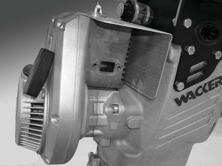
59 Repair 4.17 Engine Cooling Fins Recommended Tools Screwdriver Compressed air Engine and Upper Machine Components The Wacker WM 80 engine is air cooled, so dirt accumulation between the cylinder ribs may cause the engine to overheat. Use a screwdriver to remove any dirt that is impacted between the cylinder ribs. Clean the entire area using compressed air. wc_tx001546gb.fm 59
60 Engine and Upper Machine Components 4.18 Muffler (DS Models) Repair See Graphic: wc_gr001315rm Recommended Tools Ratchet wrench Torque wrench Hex key: 5 mm Hex key or hex socket: 6 mm Socket: 19 mm (3/4 ) Loctite 243 (blue) Carbon deposits can form in the muffler (a) and in the cylinder exhaust port. If allowed to accumulate, they will gradually restrict the exhaust passages resulting in poor engine performance and hard starting. Factors contributing to this problem include: Dirty air filter causing the engine to run rich Excessive engine idling Remove the two nuts (b) and two screws (c) holding the muffler to the engine cylinder. When reinstalling the muffler, apply Loctite 243 and torque the screws to 23 Nm (17 ft.lbs.) Remove the muffler Remove any carbon deposits on the engine exhaust port with a blunt scraper Replace the muffler gasket (d) P/N Soak the muffler in carburetor cleaner or a similar cleaning solution for several hours Drain the muffler and blow it dry. 60 wc_tx001546gb.fm
61 Repair Engine and Upper Machine Components > M? C H! # H wc_tx001546gb.fm 61
62 Engine and Upper Machine Components Repair 4.19 Replacing the Walbro Carburetor (auto-release choke models) Removal Stop the machine and allow it to cool Remove the carburetor guard (a) Loosen the hose clamp and remove the air duct (b) Disconnect the ignition wire (c) from the spark plug Loosen the clamp (d) and remove the throttle cable (e) from the carburetor adapter (f) Remove the two nuts and washers and remove the carburetor assembly (g) from the machine. This procedure continues on the next page. 62 wc_tx001546gb.fm
 and drain it. 4.19.9 Remove the gasket (m). 4.19.10 Disassemble the carburetor (i) from the adapter (j), flange (k), and gaskets (l and o).")
63 Repair Engine and Upper Machine Components Continued from the previous page Have a container ready, then remove the oil hose (h) and drain it Make sure the throttle is in the OFF position. This position also closes the fuel valve. Then, remove the fuel hose (n) and drain it Remove the gasket (m) Disassemble the carburetor (i) from the adapter (j), flange (k), and gaskets (l and o). Result The removal procedure is now complete. wc_tx001546gb.fm 63
64 Engine and Upper Machine Components Repair Installation Perform the procedure below to install the carburetor Assemble the adapter (j), lower gasket (l), flange (k), and upper gasket (o) to the carburetor (i). Note: The gaskets are not interchangeable Connect the oil hose (h), and the fuel hose (n), to the carburetor Install the carburetor assembly to the engine. 64 wc_tx001546gb.fm
 through the adapter (f) and reconnect it to the clamp")

65 Repair Engine and Upper Machine Components Slide the throttle cable (e) through the adapter (f) and reconnect it to the clamp (d). d Install the air duct (b) with the hose clamp. wc_gr Using Loctite 243 on the screws, install the carburetor guard (a). Result The installation procedure is now complete. wc_tx001546gb.fm 65
. 4.20.3 Remove the bracket (b). 4.20.4 Disconnect the wiring to the switches (c). 4.20.5 Remove the screws that hold the engine and remove the engine (d) from the machine.")
66 Engine and Upper Machine Components 4.20 Replacing the WM 80 Engine (2010 and later models) Repair Requirements Engine cool Carburetor removed Removal Perform the procedure below to remove the engine Remove the carburetor. See topic Removing the Carburetor Remove the muffler (a) Remove the bracket (b) Disconnect the wiring to the switches (c) Remove the screws that hold the engine and remove the engine (d) from the machine. Result The engine has now been removed. 66 wc_tx001546gb.fm
. 4.20.2 Reconnect the wiring (c) to the switches. 4.20.3 Install the bracket (b). 4.20.4 Install the muffler (a). Torque screws (x) to 18 Nm (13 ft.lbs.). Torque screw (y) to 23 Nm (16 ft.")
67 Repair Installation Engine and Upper Machine Components Perform the procedure below to install the engine Install the engine (d) to the machine with three screws. Torque the screws to 28 Nm (20 ft.lbs.) Reconnect the wiring (c) to the switches Install the bracket (b) Install the muffler (a). Torque screws (x) to 18 Nm (13 ft.lbs.). Torque screw (y) to 23 Nm (16 ft.lbs.) Install the carburetor. Result The engine has now been installed. wc_tx001546gb.fm 67


 from the")
. 4.21.")
. 4.21.")
 and the carburetor from the machine. 4.21.")
68 Engine and Upper Machine Components 4.21 Removing Walbro Carburetor (standard choke models) Repair Stop the machine and allow it to cool Place the throttle in the OFF position Disconnect the ignition wire (a) from the spark plug Remove the carburetor guard (b) Loosen the hose clamp (c) and remove the air duct (d) Remove the two screws and remove the flange (e) and the carburetor from the machine Remove the screws (f) and remove the adapter (g) Disconnect the throttle cable (h). Remove the spring (i). 68 wc_tx001546gb.fm
69 Repair Engine and Upper Machine Components 4.22 Replacing the WM 80 Engine (pre-2010 models) See Graphic: wc_gr Removal: Stop the machine and allow it to cool Remove the carburetor. See section Removing Carburetor Remove the muffler guard (a) (if equipped) and the muffler (b) Disconnect the connector (c) from the stop switch Remove the three socket head cap screws (d) that hold the engine to the crankcase Tilt the engine down and away to remove it from the crankcase. NOTICE: The rammer tips easily when the engine is removed. DO NOT run the engine while it is off the machine unless the clutch (e) has been removed. Running the engine with the clutch attached to the crankshaft will cause the clutch shoes to separate and fly off. WARNING Installation: Position the engine onto the machine. Using Loctite 234 or equivalent on the three screws (d), secure the engine to the machine. Torque the screws to 27 Nm (20 ft.lbs.) Reconnect the stop switch Install the muffler (b) and muffler guard (a) Install the carburetor. See section Removing Carburetor. wc_tx001546gb.fm 69


70 Engine and Upper Machine Components Repair b d e a c d wc_gr wc_tx001546gb.fm
71 Repair Engine and Upper Machine Components 4.23 Replacing the Carburetor (WM 100 Engines) Requirements Machine shut down and cool Loctite 243 or equivalent Torque wrench Removal Perform the procedure below to remove the engine Disconnect the spark plug Remove the side guard (a) Disconnect the throttle cable (b) Disconnect the air hose (c) Disconnect the fuel hose (d) and the compensation hose (h) Disconnect the hose (e). wc_tx001546gb.fm 71

72 Engine and Upper Machine Components Repair Remove screw (f) and disconnect the linkage Remove the carburetor (g). Result The removal procedure is now complete. 72 wc_tx001546gb.fm
, gaskets (h), and adapter (i). 4.23.2 Reconnect the linkage with screw (f).")
. wc_tx001546gb.fm 73")
73 Repair Engine and Upper Machine Components Installation Perform the procedure below to install the carburetor Install the carburetor (g), gaskets (h), and adapter (i) Reconnect the linkage with screw (f) Reconnect the hose (e) Reconnect the fuel hose (d) and the compensation hose (h) Reconnect the air hose (c) Reconnect the throttle cable (b). wc_tx001546gb.fm 73


74 Engine and Upper Machine Components Repair Install the side guard (a). Result The replacement procedure is now complete. 74 wc_tx001546gb.fm
75 Repair Engine and Upper Machine Components 4.24 Replacing the WM 100 Engine Requirements Machine shut down and cool Loctite 243 or equivalent Torque wrench Two wire ties Removal Perform the procedure below to remove the engine Remove the carburetor. See topic Replacing the Carburetor (WM 100 engine) Clip the wire ties (h) Remove the screws (b) that hold the low oil shutdown switch Remove the lower guard (c) Remove the support bracket (d) Remove the heat shield (a). wc_tx001546gb.fm 75

76 Engine and Upper Machine Components Repair Disconnect the throttle cable (x) at the swivel (y) and the clamp (z) Remove the nuts that hold the engine and remove the engine (e) from the machine. Result The removal procedure is now complete. 76 wc_tx001546gb.fm
. 4.24.2 Slide the engine (e) (with clutch installed) into the machine.")
. 4.24.")

. Torque the support bracket screw (n) to 25 Nm (18 ft.")
77 Repair Engine and Upper Machine Components Installation Perform the procedure below to install the engine Apply Loctite 243 to the four engine studs (w) Slide the engine (e) (with clutch installed) into the machine Loosely install the support bracket (d) and heat shield (a) with nut (n). Install the other three nuts and torque them to 25 Nm (18 ft.lbs.) Reconnect the throttle cable (x) to the swivel (y) and the clamp (z) Fit the lower guard to the support bracket. Then, using Loctite 243 on the screws, install the lower guard (c) to the engine. Torque the screws to 25 Nm (18 ft.lbs.). Torque the support bracket screw (n) to 25 Nm (18 ft.lbs.) Install the low oil shutdown switch with screws (b). wc_tx001546gb.fm 77

78 Engine and Upper Machine Components Secure the wiring with new wire ties (h). Repair Reinstall the carburetor. See topic Replacing the Carburetor. Result The replacement procedure is now complete. 78 wc_tx001546gb.fm
79 Repair 4.25 Removing the WM 90 Engine Engine and Upper Machine Components See Graphic: wc_gr001954, wc_gr003661, wc_gr001956, and wc_gr Disconnect the spark plug cap (a) from the spark plug Disconnect the fuel line (b) from the carburetor and plug the line Disconnect the stop switch wire (c) Disconnect the wiring (k) from the low-oil unit (l) (if equipped) Remove the M8 x 16 bolt and washer (d) securing the guard to the engine Remove the M8 bolt and washer (e) securing the guard to the rammer crankcase Remove the six M8 bolts (f) securing the lower guard to the engine and remove the guard Remove the wire running from the engine to the low-oil unit (if equipped) Loosen the retainer (g) from the throttle cable. Pry open the clamp (h) and remove the throttle cable Loosen the clamp (i) securing the air intake hose to the carburetor and remove the hose Remove the four nuts (j) securing the engine to the adapter and remove the heat shield and the engine. wc_tx001546gb.fm 79


80 Engine and Upper Machine Components Repair d c a k b f l j e wc_gr wc_gr wc_tx001546gb.fm
81 Repair 4.26 Engine (DS Models) Engine and Upper Machine Components See Graphic: wc_gr001317rm Recommended Tools Ratchet wrench Torque wrench Socket: 19 mm (3/4 ) Hex key: 5 mm Hex key or hex socket: 4 mm, 6 mm Screwdriver Close the fuel valve Disconnect the fuel lines Loosen the throttle cable holder Disconnect the throttle cable Remove the four M10 nuts (a) that hold the engine to the crankcase. When reinstalling the engine, torque the nuts to 49 Nm (36 ft.lbs.) Tilt the engine down and away to remove it from the crankcase. NOTICE: The rammer tips easily when the engine is removed. DO NOT run the engine while it is detached from the machine unless the clutch has been removed. Running the engine with the clutch attached to the crankshaft will cause the clutch shoes to separate and WARNING fly off. wc_tx001546gb.fm 81
82 Engine and Upper Machine Components Repair = M? C H! % H 82 wc_tx001546gb.fm
83 Repair 4.27 Clutch (2- and 4-stroke models) See Graphic: wc_gr Recommended Tools Impact wrench Torque wrench Socket: 17 mm Needle-nose pliers Clutch puller P/N Engine and Upper Machine Components Removal Remove the engine from the rammer Check the condition of the clutch shoes (a) and replace them if necessary. The clutch shoes should be absolutely dry. If oil is present, inspect the engine shaft seal Prevent the clutch from turning and use an air impact wrench and 17 mm socket to loosen the clutch nut (b). If an impact wrench is not available, rap the wrench handle sharply to help break the nut loose. Note: Loosen the nut but do not completely remove it from the engine crankshaft. This will protect the crankshaft threads from the clutch puller screw Screw the clutch puller (P/N ) (c) (or other suitable puller) into the small holes in the clutch and turn the center screw against the end of the crankshaft until the clutch hub breaks free of the taper. Note: When reinstalling the clutch, make sure the taper in the clutch hub and on the engine crankshaft is absolutely free of any oil or grease. Installation Place the clutch on the engine crankshaft Reinstall the clutch nut and torque to 35 Nm (25 ft.lbs.) Reinstall the engine on the crankcase. wc_tx001546gb.fm 83
84 Engine and Upper Machine Components Repair BS Models 84 wc_tx001546gb.fm
85 Repair 4.28 Clutch (DS 720 only) See Graphic: wc_gr001319rm Recommended Tools Impact wrench Torque wrench Needle-nose pliers Clutch puller P/N Engine and Upper Machine Components Removal Remove the engine from the rammer Check the condition of the clutch shoes (a) and replace them if necessary. The clutch shoes should be absolutely dry. If oil is present, inspect the engine shaft seal Prevent the clutch from turning and use an air impact wrench to loosen the clutch bolt (b). If an impact wrench is not available, rap the wrench handle sharply to help break the bolt loose. Note: Loosen the bolt but do not completely remove it from the engine crankshaft. This will protect the crankshaft threads from the clutch puller screw Screw the clutch puller (P/N ) (c) (or other suitable puller) into the small holes in the clutch and turn the center screw against the end of the crankshaft until the clutch hub breaks free of the taper. Note: When reinstalling the clutch, make sure the taper in the clutch hub and on the engine crankshaft is absolutely free of any oil or grease. Installation Place the clutch on the engine crankshaft Reinstall the clutch bolt and torque to 27 Nm (20 ft.lbs.) Reinstall the engine on the crankcase. Torque the screws to 49 Nm (36 ft.lbs.) Perform an operation check. The clutch should be disengaged with the throttle at the idle position. Engine Speed (idle) (rpm): 1200 ± 200 Clutch Engagement (rpm): 2000 ± 200 wc_tx001546gb.fm 85
86 Engine and Upper Machine Components Repair DS 720 Models a c b wc_gr001319rm 86 wc_tx001546gb.fm
87 Repair 4.29 Clutch (DS 70 only) See Graphic: wc_gr002372rm Recommended Tools Impact wrench Torque wrench Needle-nose pliers Clutch puller P/N Engine and Upper Machine Components Removal Remove the engine from the rammer Check the condition of the clutch shoes (a) and replace them if necessary. The clutch shoes should be absolutely dry. If oil is present, inspect the engine shaft seal Prevent the clutch from turning and use an air impact wrench to loosen the clutch bolt (b). If an impact wrench is not available, rap the wrench handle sharply to help break the bolt loose. Note: Loosen the bolt but do not completely remove it from the engine crankshaft. This will protect the crankshaft threads from the clutch puller screw Screw the clutch puller (P/N ) (c) (or other suitable puller) into the small holes in the clutch and turn the center screw against the end of the crankshaft until the clutch hub breaks free of the taper. Installation Place the clutch on the engine crankshaft Reinstall the clutch bolt and torque to 27 Nm (20 ft.lbs.) Reinstall the engine on the crankcase. Torque the screws to 49 Nm (36 ft.lbs.) Perform an operation check. The clutch should be disengaged with the throttle at the idle position. Engine Speed (idle) (rpm): 1050 ± 50 Clutch Engagement (rpm): 2500 ± 200 wc_tx001546gb.fm 87
88 Engine and Upper Machine Components Repair DS 70 Models c b a wc_gr002372rm 88 wc_tx001546gb.fm
89 Rammer Repair 5 Ramming System Ramming System 5.1 Bellows See Graphic: wc_gr001321rm Recommended Tools Ratchet wrench Torque wrench Hex key or hex socket: 8 mm Socket: 13 mm Punch Rubber mallet Screwdriver Loctite 243 The bellows provides a flexible joint between the ramming system and the upper machinery. It seals the ramming system and provides a path for recirculating the oil. Periodically, tighten the clamps, clean the bellows, and inspect the bellows for signs of damage or leaks. Removal Drain the oil into a suitable container as described in section Ramming System Lubrication Remove the four socket head cap screws (c) that secure the ramming system to the crankcase Stand on the ramming shoe and pull up hard on the crankcase until the end plugs (h) are visible Drive out the end plugs and piston pin (g) holding the connecting rod to the ram. Do not reuse the end plugs Lift the upper machinery from the ramming system Remove the O-ring (b); do not reuse To free the guide cylinder (a) from the bellows (e), loosen the top bellows clamp (d), stand on the ramming shoe, and pull up hard on the guide cylinder To free the bellows from the protective pipe (j), loosen the bottom bellows clamp (f), stand on the ramming shoe, pull on the bellows, and rap along the bottom of the bellows with a rubber mallet. wc_tx001547gb.fm 89
90 Ramming System Rammer Repair a b c d e f g h j wc_gr001321rm Installation Oil the inner edges of the bellows Place the lower clamp (f) on the protective pipe (j) Press the bellows (e) onto the protective pipe (j) with a strong downward push Partially tighten the clamp onto the bellows Place the upper clamp (d) on the bellows Press the guide cylinder (a) onto the bellows with a strong downward push Partially tighten the spring clamp onto the bellows Install a new O-ring (b) Position the upper machinery over the guide cylinder Align the connecting rod inside the ram Install the piston pin (g) and new end plugs (h). Note: Use new end plugs whenever the piston pin has been removed. Note: To aid in installation, it may be necessary to gently heat the clamping area of the bellows with an electric heat gun. 90 wc_tx001547gb.fm
91 Rammer Repair Ramming System Fasten the guide cylinder to the crankcase. Apply Loctite 243 and torque the screws to 43 Nm (32 ft.lbs.) Lay the rammer flat on the ground and align the protective pipe with the upper machinery Position the clamps so that the clamp screws (k) are in line with the sightglass (m) Tighten the clamps and torque them to 13.5 Nm (10 ft.lbs.) Fill the ramming system with clean oil as described in section Ramming System Lubrication Run the rammer for several minutes and check it for oil leaks around the guide cylinder and the bellows. wc_tx001547gb.fm 91
92 Ramming System 5.2 Replacing the Ramming Shoe Rammer Repair Requirements Torque wrench Lifting device capable of lifting the machine Removal Perform the procedure below to remove the shoe Support the machine with a lifting device capable of lifting the weight of the machine. See chapter Technical Data for weights On machines with cast iron shoes, remove the hex head screws (a and b) that hold the shoe (c) to the machine. For all others, remove the lock nuts (d) and washers (e) that hold the ramming shoe (f) and the bottom plate (g) to the machine. b a c f e d l k a b i g j c m n o wc_gr Raise the machine off the shoe. Position the machine in a secure place Remove the plow bolts (m), (n), and (o) Remove the plow bolts (i and j), lockwashers (k), and lock nuts (l) Separate the shoe (g) from the bottom plate (f). 92 wc_tx001547gb.fm
93 Rammer Repair Installation Ramming System Follow the guidelines below when installing the shoes The plow bolts (m, n, and o) and (l and j) as well as hex bolts (a and b) have different lengths. Use the longer of the bolts where needed. b a c f e d l k a b i g j c m n o When reusing bolts, clean the threads thoroughly before use Be sure notches of plow bolts seat in grooves of shoe Torques: (Recheck torques after first five hours of use.) hex bolt (a): 85.5 Nm (63 ft.lbs.) lock nuts (e): 79 Nm (58 ft.lbs.) lock nuts (l): 24 Nm (18 ft.lbs.) wc_gr wc_tx001547gb.fm 93
94 Ramming System Notes Rammer Repair 94 wc_tx001547gb.fm
95 Rammer Repair 5.3 Spring System Cover Removal and Installation Ramming System See Graphic: wc_gr001324rm Recommended Tools Ratchet wrench Torque wrench Hex key or socket: 13 mm Hydraulic press or Two threaded rods and nuts: M8 x 120 mm or Spring box tool P/N Loctite 243 The spring system cover is under heavy pressure. It must be carefully removed and installed using either the hydraulic press, the threaded rod, or the spring box tool method. If the spring system cover is removed incorrectly, the springs can eject with enough force to cause serious injury or death! Hydraulic Press Removal Method Remove the ramming shoe per section Ramming Shoe. Separate the ramming system from the upper machinery per section Bellows Remove all but two of the socket head cap screws that hold the spring system cover to the spring cylinder Place the spring cylinder in a hydraulic press and position the head of the press in firm contact with the spring system cover Lock the press and remove the remaining two screws Slowly release the press and allow the springs to expand After all the spring pressure is released, remove the spring system cover, the gasket, and the bottom spring set. Hydraulic Press Installation Method Install the bottom spring set into the spring cylinder Place a new gasket onto the spring cylinder Center the spring cylinder, the springs, and the spring system cover under the hydraulic press ram Align the holes in the spring system cover as close as possible with the holes in the spring cylinder; dowels or steel rods can be placed in the holes to act as guides Compress the springs until the spring system cover rests on the spring cylinder Install the socket head cap screws. Apply Loctite 243 and torque the screws to 24 Nm (18 ft.lbs.) Reinstall the ramming shoe. WARNING wc_tx001547gb.fm 95
96 Ramming System Attach the ramming system to the upper machinery. Rammer Repair Hydraulic Press Method wc_gr001324rm 96 wc_tx001547gb.fm
97 Rammer Repair Ramming System See Graphic: wc_gr001325rm Threaded Rod Removal Method Remove the ramming shoe per section Ramming Shoe. Separate the ramming system from the upper machinery per section Bellows Remove the two socket head cap screws that are opposite of each other on the spring system cover Screw the two M8 x 120 threaded rods into the bottom of the spring cylinder until they bottom out Turn the nuts down each rod until they contact the spring system cover With the nuts holding the spring system cover, remove the remaining screws Evenly back off both nuts until the springs have fully expanded and the pressure is released. Make sure the threaded rods are not turning out of the cylinder while backing off the nuts. The spring system cover is under heavy pressure. It must be carefully removed and installed using either the hydraulic press, the threaded rod, or the spring box tool method. If the spring system cover is removed incorrectly, the springs can eject with enough force to cause serious injury or death! Remove the spring system cover, the gasket, and the bottom spring set. Threaded Rod Installation Method Install the bottom spring set into the spring cylinder Place a new gasket onto the spring cylinder Insert the two threaded rods through the opposite sides of the spring system cover and screw them into the spring cylinder until they bottom out Compress the springs by evenly screwing the two nuts down the threaded rods until the spring system cover makes contact with the spring cylinder Install the socket head cap screws. Apply Loctite 243 and torque the screws to 24 Nm (18 ft.lbs.) Reinstall the ramming shoe Attach the ramming system to the upper machinery. WARNING wc_tx001547gb.fm 97
98 Ramming System Rammer Repair Threaded Rod Method wc_gr001325rm 98 wc_tx001547gb.fm
99 Rammer Repair Ramming System See Graphic: wc_gr Spring Box Tool Removal Method Remove the ramming shoe per section Ramming Shoe. Separate the ramming system from the upper machinery per section Bellows Align three holes in the spring box tool (a) with three socket head cap screws in the spring system cover Remove the three socket head cap screws that align with the holes in the spring box tool Place the spring box tool on the spring system cover. Insert the three spring box screws (c) through the three selected holes in the spring box tool and turn the screws into the spring cylinder until they bottom out Turn the hex head cap screw (b) through the center of the spring box tool until the spring box tool reaches the top of the spring box screws With the spring box tool holding the spring system cover, remove the remaining spring system cover screws Back off the hex head cap screw until the springs have fully expanded and the pressure is released. The spring system cover is under heavy pressure. It must be carefully removed and installed using either the hydraulic press, the threaded rod, or the spring box tool method. If the spring system cover is removed incorrectly, the springs can eject with enough force to cause serious injury or death! Remove the spring system cover, the gasket, and the bottom spring set. Spring Box Tool Installation Method Install the bottom spring set into the spring cylinder Place a new gasket onto the spring cylinder Align three holes in the spring box tool with three holes in the spring system cover Insert the three spring box screws through the selected holes in the spring box tool and spring system cover Turn the spring box screws into the spring cylinder until they bottom out Turn the hex head cap screw through the center of the spring box tool until the spring system cover makes contact with the spring cylinder Install the socket head cap screws. Apply Loctite 243 and torque the screws to 24 Nm (18 ft.lbs.) Reinstall the ramming shoe Attach the ramming system to the upper machinery. WARNING wc_tx001547gb.fm 99
100 Ramming System Rammer Repair Spring Box Tool Method Screw Position Schraube position Qty. St. Machine Maschine La posicion del tornillo Cont. Máquina La position de vis Qté. Machine 1 2 BS45Y, BS52Y, ES45Y, ES52Y 2 2 BS60Y, GVR151Y 3 3 BS62Y, BS65y, BS600, BS650, BS700, BS60-2i, BS70-2i, BS65V, BS60-4, DS72Y, DS720, DS BS92Y, BS105Y 5 3 BS500, BS50-2I, BS50-4 a b c d wc_gr wc_tx001547gb.fm
 deep well Drift pin Torque wrench Rubber mallet Impact")
101 Rammer Repair 5.4 Spring System Ramming System See Graphic: wc_gr001327rm, wc_gr001328rm Recommended Tools Impact wrench Socket: 32 mm or 24mm (BS 500 only) deep well Drift pin Torque wrench Rubber mallet Impact bushing puller P/N Loctite 243 (blue) Disassembly Remove the ramming shoe and separate the ramming system from the upper machinery Remove the spring system cover and the spring set per section Spring System Cover Removal and Installation Loosen the nut (d) on the impact bushing puller to allow the yoke (c) to set on the flange surface of the rammer and the jaws to reach the bottom of the impact bushing Push the jaws (a) of the impact bushing puller over the impact bushing (b) until it seats at the bottom of the impact bushing Tighten the nut on the impact bushing puller to remove the impact bushing as shown in the graphic and discard Place a drift pin through the holes on the end of the ram (e) to prevent the ram from turning Use an impact wrench to remove the locknut (k) Remove the piston guide (j) Remove the spring set (g) and the bushing (f) from the spring cylinder. c d a b c wc_gr001327rm wc_tx001547gb.fm 101
102 Ramming System Rammer Repair Assembly Slide the ram (e) into the spring cylinder (h) Reinstall the bushing (f) and the spring set (g) Reinstall the piston guide (j) Replace the locknut (k) and torque it to: BS Nm (155 ft.lbs.) BS 600/ Nm (184 ft.lbs.) Press a new impact bushing (m) onto the end of the ram and seat it by hitting the end of the impact bushing with a rubber mallet Reinstall the spring set (n) Install a new gasket (o) Reinstall the spring system cover (p) using one of the three methods described in section Spring System Cover Removal and Installation. Apply Loctite 243 and torque the screws to 24 Nm (18 ft.lbs.). f m e g n h j k o p wc_gr001328rm 102 wc_tx001547gb.fm

103 Rammer Repair 5.5 Inspecting the Spring System Ramming System See Graphic: wc_gr001329rm Over time, the constant compression and release of the spring pressure can cause the springs to wear out. If the rammer feels to be hitting with less force, it is possible that the springs are worn and should be replaced. A broken spring causes the rammer to jump erratically. This condition is more noticeable on hard soils. Do not run the rammer if a broken spring is suspected. Doing so may damage other rammer parts. Replace both the top and the bottom spring sets even if only one set is worn or damaged Remove the springs from the cylinder and check them for minimum spring free height and maximum spring height difference per the table below. Replace the springs if they do not meet the given specifications If a spring has broken, inspect the inside of the spring cylinder wall for burrs, gouges, and cracks as follows: Slide the piston guide inside the cylinder. Check that the piston guide moves freely but without excessive side play. Hone the cylinder to remove the ridges and the burrs that were cut into the cylinder wall by the spring movement. Replace the cylinder if it is badly worn. Minimum spring free height (a) Maximum spring height difference (b) BS 500, BS mm (7 21/32 in.) 5 mm (3/16 in.) BS 600, BS 60 BS 700, BS 70 BS 650, BS 65V DS 720, DS mm (8 9/16 in.) 5 mm (3/16 in.) b a wc_gr001329rm wc_tx001547gb.fm 103
104 Ramming System 5.6 Protective Pipe Rammer Repair See Graphic: wc_gr001330rm Recommended Tools Ratchet Wrench Torque Wrench Extension Hex Socket: 6 mm Loctite 243 (Blue) If the protective pipe becomes loose or damaged, it must be replaced on the spring cylinder Remove the bellows following the procedures in section Bellows Remove the socket head cap screws (c). To reinstall the protective pipe, apply Loctite 243 and torque the screws to 24 Nm (18 ft.lbs.) Reassemble the rammer following the previous procedures. c wc_gr001330rm 104 wc_tx001547gb.fm
105 Rammer Repair Ramming System 5.7 Ramming System Lubrication (BS 500/600/700/650, DS 720) See Graphic: wc_gr001331rm Recommended Tools Hex Key: 8 mm Ratchet Wrench Torque Wrench Extension Sockets: 19 mm (3/4 ), 27 mm (1 1/16 ) Teflon Tape Oil for lubrication is carried throughout the ramming system by the action of the rammer. Holes drilled in the piston allow the oil to be distributed from the bottom of the rammer to the crankcase. Oil in the ramming system must be maintained at the correct level to ensure the system operates efficiently. Check oil level: Check the oil level in the sightglass (a) daily before starting the rammer. When checking the oil, make sure the rammer is on a flat, level surface. The oil level should fill 1/2 3/4 of the sightglass. Add the oil though the fill plug (c) located in the filter housing at the top of the rammer. See section Technical Data for oil quantity and type. Change the ramming system oil after the first 50 hours of operation and then after every 300 hours of use. Oil change: Remove the oil fill plug (c) and the seal ring BS 500: Remove the sightglass. BS 600/700/650, DS720: Remove the drain plug (b) Tilt the rammer back until it is resting on its handle Allow the oil to drain Wrap the sightglass threads with Teflon tape Reinstall the sightglass or the drain plug, and torque to 9.5 Nm (7 ft.lbs.) Stand the rammer upright on a level surface Add oil through the fill plug. Proper ramming system lubrication is indicated when approximately 1/2 3/4 of the sightglass is full. NOTICE: It may take some time for the oil to filter down to the sightglass. Use care not to overfill the ramming system. Excessively high levels of oil can create a hydraulic lock in the ramming system. This can result in erratic operation and cause damage to the engine clutch, the ramming system, and the shoe. wc_tx001547gb.fm 105
106 Ramming System Rammer Repair Reinstall the seal-ring and the fill plug. Torque the fill plug to 47 Nm (35 ft.lbs.). Note: An alternate method of changing the oil is to drain and fill the oil from the sightglass. a c b wc_gr001331rm 106 wc_tx001547gb.fm
107 Rammer Repair Ramming System 5.8 Ramming System Lubrication (BS 50/60/70, BS 65, DS 70) Background Lubricating oil is distributed throughout the ramming system by the action of the rammer. Holes drilled in the piston carry oil from the bottom of the rammer to the crankcase as the rammer operates. Oil in the ramming system must be maintained at the correct level to ensure the ramming system operates efficiently. Checking the oil level Perform the following procedure to check the ramming system oil level. Note: If the Rammer has been transported in the horizontal position or has recently been used, upright it and allow it to stand in the upright position for 15 minutes before checking the oil level. This will allow the oil to settle and provide a more accurate reading Tip the rammer so that it is perpendicular with the ground Check the oil through the sightglass (a). The correct oil level will fill 1/2 to 3/4 of the sightglass. Add more oil if necessary. Adding oil Perform the following procedure to add oil to the ramming system. NOTICE: Do not overfill the ramming system with oil. Excessively high levels of oil can create a hydraulic lock in the ramming system. This can result in erratic operation and cause damage to the engine clutch, the ramming system, and the shoe Tip the Rammer forward to allow access to the sightglass. Secure the Rammer in this position. wc_tx001547gb.fm 107
108 Ramming System Rammer Repair Remove the sightglass. Clean the threads of the sightglass, then wrap the threads with Teflon tape Add oil to the machine through the sightglass opening in the housing Stand the machine upright to check the oil level. Add enough oil so that when the machine is upright, oil will fill 1/2 to 3/4 of the sightglass. At that point, install the sightglass. Torque the sightglass to 9 Nm (6 ft.lbs.). Changing oil Perform the following procedure to change the ramming system oil. Note: Dispose of used oil in accordance with local environmental regulations Remove the drain plug (b). (On BS 50 machines, remove the sightglass (a).) Tilt the rammer backward until it is resting on the handle and drain the oil into a suitable container. Note: It may take up to 10 minutes for the oil to drain Reinstall the drain plug. Torque it to 54 Nm (40 ft.lbs.) Add oil as stated above. 108 wc_tx001547gb.fm
109 Rammer Repair 6 Crankcase Crankcase 6.1 Crank Gear and Connecting Rod See Graphic: wc_gr Recommended Tools Hex key: 8 mm 2-Jaw bearing puller Large diameter retaining-ring pliers Hydraulic press Screwdriver Split puller Slide hammer Torque wrench Loctite 243 (blue) Removal Remove the four socket head cap screws that secure the ramming system to the crankcase Stand on the ramming shoe and pull up hard on the crankcase until the pin holding the connecting rod to the ram is visible Drive out the end plugs and the piston pin Lift the upper machinery from the ramming system Remove the four socket head cap screws (a) from the front cover Insert a screwdriver into the slots on each side of the cover and pry off the cover. The cover will come out with the crank gear (g) and the connecting rod (k) attached. Note: The crankcase cover cannot be removed until the connecting rod is detached from the ram Reach through the slotted hole (m) in the crank gear and release the large retaining ring (f) Thread two M8 socket head cap screws, or threaded rods, through the pusher holes (n) in the crank gear. Turn the screws into the crank gear to free the crank gear and the bearing from the cover Remove the small retaining ring (d) securing the bearing (e) to the crank gear Pull the bearing free of the shaft using the split puller (p) and a 2-jaw bearing puller (o) Remove the small retaining ring (h) that holds the connecting rod and the bearing (j) to the crank gear Pull the connecting rod off the crank gear with a 2-jaw bearing puller Press the bearing out of the connecting rod. wc_tx001548gb.fm 109


110 Crankcase Rammer Repair The needle bearing (c) remains intact in the crankcase cover. Inspect the needle bearing for wear and, if damaged, remove it by using a slide hammer or similar pulling device. c d e f g k j h b m f f n p a wc_gr Assembly If the needle bearing was removed, press a new bearing into the cover until the outer race is flush with the flange surface Place the large retaining ring over the crank gear shaft Press the ball bearing onto the crank gear shaft and reinstall the small retaining ring Press the connecting rod assembly onto the crank gear and secure it in place with the small retaining ring Push the complete crank gear assembly into the bearing housing and seat the retaining ring in the groove Replace the o-ring (b) Assemble the cover to the crankcase. Torque the screws to 49 Nm (36 ft.lbs.) Connect the crankcase to the ramming system as follows: Position the upper machinery over the guide cylinder. Align the connecting rod inside the ram. Install the piston pin and the end plugs. Note: Use new end plugs whenever the piston pin has been removed. Fasten the guide cylinder to the crankcase. Apply Loctite 243 and torque the screws to 43 Nm (32 ft.lbs.). 110 wc_tx001548gb.fm
111 Rammer Repair Crankcase 6.2 Crank Gear, Connecting Rod, and Adjuster Assembly (BS 650/65 only) See Graphic: wc_gr001334rm Recommended tools Hex key: 8 mm 2-Jaw bearing puller Large diameter retaining-ring pliers Hydraulic press Screwdrivers or pry bars Split puller Slide hammer Punch Torque wrench Loctite 243 (blue) Removal Remove the four socket head cap screws that secure the ramming system to the crankcase Stand on the ramming shoe and pull up hard on the crankcase until the pin holding the connecting rod to the ram is visible Drive out the end plugs and the piston pin Lift the upper machinery from the ramming system Open the front cover and remove the four socket head cap screws (31) from the bearing mount (16) Insert a screwdriver on each side of the bearing mount and pry it off. The bearing mount and cover will come out with the crank gear (20) and the connecting rod (24) attached. Note: The bearing mount and cover cannot be removed until the connecting rod is detached from the ram Remove the snap ring (25), then pry off the connecting rod assembly (24) with two pry bars Press the ball bearing (27) out of the connecting rod Turn the assembly over and open up the crankcase cover Remove the two retaining rings (3) and drive the pin (13) out of the yoke (4) with a hammer and punch Remove the screws (12) and clamping ring (5), then slide out the adjusting plate (6) and two Belville spring washers (7). The eccentric drive shaft (23), pin (28), and spring (29) will also slide out. Pull out the O-ring (21) Remove the small retaining ring (9)and press the crank gear (20) from the bearing mount. wc_tx001548gb.fm 111
112 Crankcase Rammer Repair The crankgear needle bearing (19), oil seal (11), and ball bearing (10) remain intact in the bearing mount. Examine the needle bearings for wear. If damaged, replace the needle bearings by removing the large retaining ring (8) holding the ball bearing to the bearing mount and press out the needle bearings and seal. Replace the needle bearings and oil seal together Remove the O-ring (18) and discard it The clutch drum needle bearing (17) will remain intact in the bearing mount. Inspect it for wear and if damaged, remove and replace it. 112 wc_tx001548gb.fm
113 Rammer Repair Crankcase Assembly If the needle bearing (17) was removed, apply Loctite 609 to a new needle bearing and press it into the bearing mount until the outer race is flush with the flange surface Press the ball bearing (27) into the connecting rod Press the connecting rod assembly (24) onto the eccentric drive shaft (23) and secure it in place with the small snap ring (25) Press the crank gear (20) into the bearing mount (16) and secure it with the small retaining ring (9). Note: If the small pin (30) was removed, replace it leaving a ½-inch showing. DO NOT bottom the pin in the hole Grease O-ring (21) thoroughly and insert it into the crank gear Ensure the arrow label (22) is in place, then slide the eccentric drive shaft (23) and the spring (29) and pin (28) into the crank gear Place the two Belville spring washers (7) onto the eccentric drive shaft so that the outer edges are facing each other Place the adjusting plate (6) over the Belville spring washers, lining up pin (30) at position Place the clamping ring (5) over the adjusting plate. Apply Loctite 243 to the screws (12) and torque to 9.5 Nm (7 ft.lbs.). Tighten the screws evenly to compress the Belville spring washers Fit the yoke (4) over the eccentric drive shaft (23) and secure in place with pin (13). Secure the pin with the two retaining rings (3). Note: Install with the lever open and spring tension relaxed. When CLOSED, the lever should point in the same direction as the arrow Insert a new O-ring (18) Push the complete crank gear assembly into the bearing housing and seat the retaining ring in the groove Assemble the bearing mount to the crankcase. Apply Loctite 243 and torque the screws (31) to 49 Nm (36 ft.lbs.) Connect the crankcase to the ramming system as follows: a. Position the upper machinery over the guide cylinder. b. Align the connecting rod inside the ram. c. Install the piston pin and the end plugs. Note: Use new end plugs whenever the piston pin has been removed. d. Fasten the guide cylinder to the crankcase. Apply Loctite 243 and torque the screws to 43 Nm (32 ft.lbs.). wc_tx001548gb.fm 113
114 Crankcase Notes Rammer Repair 114 wc_tx001548gb.fm
115 Rammer Repair 6.3 Clutch Drum Crankcase See Graphic: wc_gr001335rm Recommended Tools Hex Key: 8 mm Large diameter retaining-ring pliers Hydraulic press Screwdriver Slide hammer Torque wrench Loctite 243 (blue) Shell Alvania RL2 Removal Remove the four socket head cap screws that secure the ramming system to the crankcase Stand on the ramming shoe and pull up hard on the crankcase until the pin holding the connecting rod to the ram is visible Drive out the end plugs and the piston pin Lift the upper machinery from the ramming system Remove the engine Remove the four socket head cap screws from the front cover Insert a screwdriver into the slots on each side of the cover and pry off the cover. The cover will come out with the crank gear and the connecting rod attached. Note: The crankcase cover cannot be removed until the connecting rod is detached from the ram Remove the small retaining ring (b) from the clutch drum shaft (f) inside the crankcase Press the clutch drum free of the crankcase Remove the shaft seal (e) Remove the large retaining ring (d) Press the clutch drum bearing (c) from the crankcase The needle bearing (a) remains intact in the crankcase cover. Inspect the needle bearing for wear and, if damaged, remove it by using a slide hammer or similar pulling device. wc_tx001548gb.fm 115
116 Crankcase Rammer Repair a b c d e f wc_gr001335rm Assembly If the needle bearing was removed, press a new bearing into the cover until the outer race is flush with the flange surface. NOTICE: Keep the inside of the clutch drum absolutely free of any oil and grease Press the clutch drum ball bearing into the crankcase Secure the bearing with the large retaining ring Pack the shaft seal cavity with Shell Alvania RL2 grease. Install the shaft seal with the open side facing toward the bearing Press the clutch drum into the crankcase Secure the clutch drum with the small retaining ring Assemble the cover to the crankcase. Apply Loctite 243 and torque the screws to 49 Nm (36 ft.lbs.) Connect the crankcase to the ramming system as follows: a. Position the upper machinery over the guide cylinder. b. Align the connecting rod inside the ram. c. Install the piston pin and the end plugs. Note: Use new end plugs whenever the piston pin has been removed. d. Fasten the guide cylinder to the crankcase. Apply Loctite 243 and torque the screws to 43 Nm (32 ft.lbs.). 116 wc_tx001548gb.fm
117 Rammer Repair 7 Oil Injection (if equipped) 7.1 Testing the Float Switch (2010 and later models) Oil Injection (if equipped) Background The function of the float switch is to prevent the engine from running without oil in the oil tank. If the oil tank is low on oil, the float switch opens and kills the ignition. A severed float switch wire will also kill the ignition. In the event that the engine runs but shuts off by itself within approximately 25 seconds, even with oil in the oil tank, the float switch could be faulty. Requirements Machine shut down and cool Multimeter Oil tank at least 1/4 full Procedure Perform the procedure below to test the float switch Remove the carburetor guard (a) Disconnect the float switch wiring (c). wc_tx001549gb.fm 117
118 Oil Injection (if equipped) Rammer Repair Check the continuity of the float switch by measuring across the connector. Does the float switch have continuity? Yes No The float switch is OK. The float switch has failed; replace it Reconnect the float switch Reinstall the carburetor guard. 7.2 Replacing the Float Switch (2010 and later models) Requirements New float switch 2-cycle engine oil Removal Perform the procedure below to remove the float switch Remove the silencing cover. See topic Removing the Silencing Cover Remove the carburetor guard (a) Disconnect the float switch wiring (c) Locate the oil tank (d). 118 wc_tx001549gb.fm


. Result The replacement procedure is now complete. wc_tx001549gb.fm 119")
119 Rammer Repair Oil Injection (if equipped) Remove the screws that hold the oil tank and turn it upside down Unscrew the float switch assembly (e) from the oil tank Remove the float switch and wiring from the machine. Installation Perform the procedure below to install the float switch Screw the new float switch assembly into the oil tank Thread the wiring through the machine to the engine Reinstall the oil tank. Torque screws to 9 Nm (6 ft.lbs.) Reinstall the silencing cover Connect the wiring to the engine Reinstall the carburetor guard. Torque screws to 23 Nm (16 ft.lbs.). Result The replacement procedure is now complete. wc_tx001549gb.fm 119
120 Oil Injection (if equipped) Rammer Repair 7.3 Float Switch Testing and Replacement (pre-2010 models) See Graphic: wc_gr NOTICE: Do not bypass the float switch except during testing; engine failure may occur. The function of the float switch is to prevent the engine from running without oil in the oil tank. If the oil tank is low on oil, the float switch opens and kills the ignition. A severed float switch wire will also kill the ignition. In the event that the engine runs but shuts off by itself within approximately 25 seconds, even with oil in the oil tank, the float switch could be faulty. To test the float switch (a): Remove the carburetor guard (d) Inspect the float switch wire for damage. If damage is present, replace the float switch. If no damage to the float switch wire is obvious and the connector is fully seated at the engine (b), continue Unplug the float switch wire from the engine Insert a jumper wire into the terminal on the engine to connect the two terminal leads Start the engine and run it at idle. If the engine continues to run for more than 45 seconds, the float switch is faulty and must be replaced. If the engine still shuts off within 25 seconds, the ignition module has failed and must be replaced. To replace the float switch: Drain the remaining oil from the oil tank or position the rammer so that the oil in the tank will not run out when the float switch is removed Remove the oil line from the float switch Disconnect the float switch from the back of the engine Unscrew the float switch assembly from the oil tank Screw a new float switch assembly into the oil tank Install the oil line to the float switch. Ensure that the oil line from the oil tank is routed through the coiled portion (c) of the float switch wire near the switch Ensure that the float switch plug is fully seated in the connector on the back of the engine. 120 wc_tx001549gb.fm


121 Rammer Repair Oil Injection (if equipped) d a c b wc_gr wc_tx001549gb.fm 121
122 Oil Injection (if equipped) 7.4 Oil Line Check Valve Rammer Repair See Graphic: wc_gr The the function of the oil line check valve (a) is to prevent raw fuel from backing up to the oil pump. It is important that the check valve be installed in the correct direction. Looking at the side of the check valve, one should notice recessed areas with pointed ends or an arrow (b). The pointed ends or the arrow must point towards the fuel line. This is the direction of oil flow. To test the check valve: The oil line check valve is spring operated and is designed to release at 1.5 psi. Note: Initial release can be as high as 4.5 psi Remove the oil line check valve from the oil line Attach a hand-operated vacuum pump to the outlet side (pointed end) of the oil line check valve and operate the vacuum pump until the vacuum overcomes the oil line check valve spring. Measure how much vacuum it takes to operate the oil line check valve. A vacuum reading of more than 2 psi (after initial release) is grounds for replacing the oil line check valve. Note: The oil line check valve is only available by replacing the entire hose assembly. Newly installed oil line check valves (and those that have lost their prime) require priming. There are two methods of priming the oil line check valve line with oil. Vacuum method: Attach a hand-operated vacuum pump to the fuel line end of the oil hose Place the oil pump side of the hose in a container of 2-cycle oil Operate the vacuum pump until the oil reaches the vacuum pump Install the oil line to the oil pump and to the fuel line. Pressure method: Attach a syringe filled with 2-cycle oil to the oil pump end of the hose Inject the oil into the hose until it passes through the oil line check valve Attach the oil line to the oil pump. NOTICE: The oil line check valve is an important part of the oil injection system and should not be bypassed. Engine failure may occur. 122 wc_tx001549gb.fm
 b a wc_gr001527")
123 Rammer Repair Oil Injection (if equipped) b a wc_gr wc_tx001549gb.fm 123
124 Oil Injection (if equipped) 7.5 Testing/Replacing the Oil Pump Rammer Repair Background Requirements Oil-injection Rammers can run up to 65 hours on one tank of oil. If the Rammer has been used for a long period of time, and it does not appear to have used any oil and the oil line check valve is operating correctly, remove and check the oil pump. Carburetor removed Engine removed Oil tank at least 1/4 full Removal and testing Perform the procedure below to check the oil pump Remove the carburetor. See topic Removing the Carburetor Remove the engine. See topic Removing the Engine Remove the output hose (a) from the oil pump. Do not remove the input hose Remove the three screws (b) that hold the pump assembly to the engine Separate the pump from the cartridge portion of the pump assembly. The cartridge may remain in the engine. 124 wc_tx001549gb.fm

 within the pump housing.")

125 Rammer Repair Oil Injection (if equipped) Inspect the gear (c) for damage. If the gear is damaged, replace it Open the bleed screw (d) until oil flows from the output nipple (e), then close the bleed screw Rotate the small gear (f) within the pump housing. Oil should flow out of the output nipple (e) within 20 revolutions of the small gear. If no oil flows out of the output nipple, replace the pump. Note: The pump puts out a 0.8 mm (0.030 in.) droplet of oil every 7 9 seconds of running at 4350 rpm Remove the cartridge assembly (g). Result The removal procedure is now complete. wc_tx001549gb.fm 125
. 7.5.3 Reconnect the output hose (a). 7.5.4 Reinstall the engine. 7.5.5 Reinstall the carburetor. Result The replacement procedure is now complete.")
126 Oil Injection (if equipped) Rammer Repair Installation Perform the procedure below to install the oil pump Slide the cartridge assembly (g) into the crankcase Install the pump to the machine using three screws (b). Torque the screws to 17 Nm (12 ft.lbs.) Reconnect the output hose (a) Reinstall the engine Reinstall the carburetor. Result The replacement procedure is now complete. 126 wc_tx001549gb.fm
.")

127 Rammer Repair 8 Low Oil Shutdown (if equipped) Low Oil Shutdown (if equipped) 8.1 Testing the Low Oil Unit See Graphic: wc_gr The function of the low oil unit is to prevent the engine from running after startup if the engine is low on oil. To test the low oil unit: Remove the lower engine guard (a) Lay the machine down and remove the low oil unit (b) from the crankcase Disconnect the wiring from the engine to the low oil unit Attach a 9V battery to the low oil unit as shown. A functioning low oil unit should flash at a steady rate. If the low oil unit does not flash at a steady rate, it has failed; replace it. If the low oil unit does flash at a steady rate, continue Grasp the sensors (c) with your fingertips. This action will change the capacitance of the sensors, and will change the flashing action (duty cycle) of the low oil unit from a period where the light remains on longer than it is off, to one where the light is off longer than it is on. If the low oil unit performs accordingly, it is functioning properly. If the low oil unit does not perform accordingly, it has failed; replace it. b a + 1 Hz 1 Hz 1 Hz wc_gr wc_tx001550gb.fm 127
en Vibroplate VP 1550 (RAW) OPERATOR S MANUAL
 OPERATOR S MANUAL") www.wackergroup.com 0157759en 001 0703 Vibroplate VP 1550 (RAW) OPERATOR S MANUAL 0 1 5 7 7 5 9 E N VP 1550 (RAW) Table of Contents 1. Foreword 2 2. Safety Information 3 2.1 Laws Pertaining to Spark Arresters...
www.wackergroup.com 0157759en 001 0703 Vibroplate VP 1550 (RAW) OPERATOR S MANUAL 0 1 5 7 7 5 9 E N VP 1550 (RAW) Table of Contents 1. Foreword 2 2. Safety Information 3 2.1 Laws Pertaining to Spark Arresters...
Operator s Manual. Inverter Generator. GPi en
 Operator s Manual Inverter Generator GPi 1700 0179739en 002 0311 0 1 7 9 7 3 9 E N Copyright notice Copyright 2010 by Wacker Neuson Corporation. All rights, including copying and distribution rights, are
en Backpack Vibrator BV 35A-P BV 50A-P OPERATOR S MANUAL
 0171881en 003 0708 Backpack Vibrator BV 35A-P BV 50A-P OPERATOR S MANUAL 0 1 7 1 8 8 1 E N BV Table of Contents 1. Foreword 5 2. Safety Information 6 2.1 Laws Pertaining to Spark Arresters... 6 2.2 Operating
Repair Manual. Roller RD 12
 Repair Manual Roller RD 12 EN 5000192242 02 0912 5 0 0 0 1 9 2 2 4 2 Copyright notice Copyright 2012 by Wacker Neuson Production Americas LLC All rights, including copying and distribution rights, are
Operator s Manual. Inverter Generator. GPi 1700
 Operator s Manual Inverter Generator GPi 1700 EN 5000186370 05 0813 5 0 0 0 1 8 6 3 7 0 Copyright notice Copyright 2013 by Wacker Neuson Production Americas LLC All rights, including copying and distribution
OPERATING INSTRUCTIONS. Vibratory Plate Compactor SPHZR106A
 SMHZR106-02 Before using the machine, please read this manual carefully. OPERATING INSTRUCTIONS Vibratory Plate Compactor SPHZR106A Table of Contents 1. Foreword.... 1. 2. Safety Information.. 1 2.1 Laws
Operator s Manual. Ride-On Roller RD en
 Operator s Manual Ride-On Roller RD 16 0178395en 005 0310 0 1 7 8 3 9 5 E N Copyright notice Copyright 2010 by Wacker Neuson Corporation. All rights, including copying and distribution rights, are reserved.
PORTABLE TRASH PUMPS MDP200
 PORTABLE TRASH PUMPS MDP200 OPERATING & PARTS MANUAL INTRODUCTION This manual provides information and procedures to safely operate and maintain the engine and pump. For your own safety and protection
Repair Manual. Engine WM en
 Repair Manual Engine WM 80 0162695en 003 0610 0 1 6 2 6 9 5 E N Copyright notice Copyright 2010 by Wacker Neuson Corporation. All rights, including copying and distribution rights, are reserved. This publication
en 002 Engine WM 130 WM 170 WM 270 OPERATOR S MANUAL
 www.wackergroup.com 0156647en 002 0405 Engine WM 130 WM 170 WM 270 OPERATOR S MANUAL 0 1 5 6 6 4 7 E N WM 130/170/270 Table of Contents 1. Foreword 2 2. Emission Control System Information 3 3. Safety
en 003 Generator GV 5600A OPERATOR S MANUAL
 www.wackergroup.com 0170813en 003 0108 Generator OPERATOR S MANUAL 0 1 7 0 8 1 3 E N DANGER CARBON MONOXIDE Using a generator indoors CAN KILL YOU IN MINUTES. Generator exhaust contains carbon monoxide
en Generator GP 2500A OPERATOR S MANUAL
 0163727en 005 0509 Generator GP 2500A OPERATOR S MANUAL 0 1 6 3 7 2 7 E N DANGER CARBON MONOXIDE Using a generator indoors CAN KILL YOU IN MINUTES. Generator exhaust contains carbon monoxide (CO). This
Table of Contents. Safety symbols... 3 Assembly 6. Operation Maintenance Troubleshooting 11. Storage. 12. Notes. 13
 Table of Contents Safety symbols... 3 Assembly 6 Operation... 8 Maintenance... 10 Troubleshooting 11 Storage. 12 Notes. 13 2 Safety Information Attention; this machine can be dangerous! All operators should
PORTABLE TRASH PUMPS MTP200 MTP300 MTP400
 PORTABLE TRASH PUMPS MTP200 MTP300 MTP400 OPERATING & PARTS MANUAL INTRODUCTION This manual provides information and procedures to safely operate and maintain the engine and pump. For your own safety and
Voltmaster Centrifugal Trash Pumps
 Voltmaster Centrifugal Trash Pumps Model TSP2, TSP3 and TSP4 Owner s Manual February 2011 Table of Contents 1 Introduction............................ 1 1.1 Read before using..................... 1 1.2
Log Splitter. Owner/Operator Manual. Models HCWP1-26
 Log Splitter Owner/Operator Manual Models HCWP1-26 SAFETY..........................2 SAFETY WARNING SYMBOL.........3 SAFETY RULES.................. 4-5 SPECIFICATIONS................. 6 CONTROLS AND FEATURES.......
TP300 INDUSTRIAL TRASH PUMP OPERATOR S MANUAL
 TP300 INDUSTRIAL TRASH PUMP OPERATOR S MANUAL IT IS EXTREMELY IMPORTANT TO READ AND UNDERSTAND THE ENTIRE CONTENTS OF THIS OPERATOR S MANUAL BEFORE ATTEMPTING TO OPERATE THE PRODUCT. THIS EQUIPMENT IS
en Walk-Behind Trowels CT 36 CT 48 REPAIR MANUAL
 www.wackergroup.com 0163091en 003 1007 Walk-Behind Trowels CT 36 CT 48 REPAIR MANUAL 0 1 6 3 0 9 1 E N CT Repair Foreword This manual covers machines with Item Number: 0009438, 0009439, 0009442, 0009443,
Operator s Manual. Vibroplate VP 1030A VP 1030AW
 Operator s Manual Vibroplate VP 1030A VP 1030AW 5000189181 14 0811 Copyright notice Copyright 2011 by Wacker Neuson Corporation. All rights, including copying and distribution rights, are reserved. This
Read instructions carefully and follow rules for safe operation. Failure to do so could result in serious injury. Fradan Manufacturing Corp.
 OPERATOR MANUAL FRADAN POWER BLOWERS Part No. 888-011-222-0 Read instructions carefully and follow rules for safe operation. Failure to do so could result in serious injury. Fradan Manufacturing Corp.
OWNER S MANUAL. Item #
 GAS-POWERED CONCRETE SCREED OWNER S MANUAL WARNING: Read carefully and understand all INSTRUCTIONS before operating. Failure to follow the safety rules and other basic safety precautions may result in
Table of Contents. Safety Assembly Pre-operation / Starting. 7. Operation.. 8. Maintenance. 9. Storage 10
 Table of Contents Safety... 3 Assembly... 6 Pre-operation / Starting. 7 Operation.. 8 Maintenance. 9 Storage 10 Parts drawings..11 Parts list by number..12 Notes.13 2 Safety Information Attention; this
GP 6600A GPS 6600A CARB
 0171950en 002 0609 Generator GP 6600A GPS 6600A CARB OPERATOR S MANUAL 0 1 7 1 9 5 0 E N DANGER CARBON MONOXIDE Using a generator indoors CAN KILL YOU IN MINUTES. Generator exhaust contains carbon monoxide
TurfMaker TAILGATE MULCHER
 TurfMaker TAILGATE MULCHER OPERATORS MANUAL AND PARTS LIST FOREWORD Congratulations on your purchase of a TurfMaker Tailgate Mulcher. You will find this to be one of the most versatile and work-saving
GV 2500A GV 3800A GV 5600A GV 6600A
 0171887en 002 0609 Generator GV 2500A GV 3800A GV 5600A GV 6600A REPAIR MANUAL 0 1 7 1 8 8 7 E N GV Generator Repair Foreword Machines covered by this manual Machine Item Number GV 2500A 0620286, 0620542
Owner s Manual. Mortar / Plaster Mixer. Models M785 M1000 M1200
 Owner s Manual Mortar / Plaster Mixer Models M785 M1000 M1200 Tiger Equipment LLC. 15 Byrd Lane Rocky Mount, VA 24151 Tel: 540-489-7777 Fax: 540-489-7778 www.tigerequip.com 1. PREFACE This manual contains
en Generator, Non-CARB GPS 8500 GPS 9700 OPERATOR S MANUAL
 0176674en 002 0809 Generator, Non-CARB GPS 8500 GPS 9700 OPERATOR S MANUAL 0 1 7 6 6 7 4 E N DANGER CARBON MONOXIDE Using a generator indoors CAN KILL YOU IN MINUTES. Generator exhaust contains carbon
Operation Manual. 10 Mini-Cultivator MODEL #
 10 Mini-Cultivator MODEL # 103350 Operation Manual This safety alert symbol identifies important safety messages in this manual. Failure to follow this important safety information may result in serious
1100W PORTABLE GENERATOR
 1100W PORTABLE GENERATOR MODEL NO: G1200 PART NO: 8010110 OPERATION & MAINTENANCE INSTRUCTIONS LS0312 INTRODUCTION Thank you for purchasing this CLARKE 1100W Portable Generator. Before attempting to use
en Generator GP 5600A GPS 5600A OPERATOR S MANUAL
 0163127en 005 1007 Generator GP 5600A GPS 5600A OPERATOR S MANUAL 0 1 6 3 1 2 7 E N DANGER CARBON MONOXIDE Using a generator indoors CAN KILL YOU IN MINUTES. Generator exhaust contains carbon monoxide
RedGum GP160 Splitter. Owner s Manual
 RedGum GP160 Splitter Owner s Manual Product Description & Intended Purpose: This Log Splitter / Wood Splitter is an outdoor product that splits wood logs for use as fuel in a fireplace or a woodstove.
Owner s/operator s Manual
 Water Pump MP2533E2 Owner s/operator s Manual Completely read and understand this manual before using this product. Foreword This Owner s/ Operator s Manual is designed to familiarize the operator with
Propane torch. Model Assembly And Operation Instructions
 Propane torch Model 39953 Assembly And Operation Instructions Due to continuing improvements, actual product may differ slightly from the product described herein. 3491 Mission Oaks Blvd., Camarillo, CA
Single and Double Head Powered Screed. Screed King. User Manual. SCR-UM EN-04 (December 2018)
") Single and Double Head Powered Screed Screed King SCR-UM-00364-EN-04 () User Manual Single and Double Head Powered Screed, Screed King CONTENTS Scope of This Manual.............................................
Single and Double Head Powered Screed Screed King SCR-UM-00364-EN-04 () User Manual Single and Double Head Powered Screed, Screed King CONTENTS Scope of This Manual.............................................
PORTABLE CONCRETE VIBRATOR
 PORTABLE CONCRETE VIBRATOR OPERATION MANUAL MODEL PV45S INTRODUCTION We have taken care in the selection, testing and design of this product. Should service or spare parts be required this can be provided
KING CANADA 950W PORTABLE GENERATOR MODEL: KCG-951G INSTRUCTION MANUAL COPYRIGHT 2011 ALL RIGHTS RESERVED BY KING CANADA TOOLS INC.
 KING CANADA 950W PORTABLE GENERATOR MODEL: KCG-951G INSTRUCTION MANUAL COPYRIGHT 2011 ALL RIGHTS RESERVED BY KING CANADA TOOLS INC. WARRANTY & SERVICE INFORMATION 1-YEAR LIMITED WARRANTY FOR THIS 950W
PROPANE TORCH WITH TURBO BURNER
 PROPANE TORCH WITH TURBO BURNER MODEL 91894 ASSEMBLY AND OPERATING INSTRUCTIONS 3491 Mission Oaks Blvd., Camarillo, CA 93011 Visit our Web site at http://www.harborfreight.com TO PREVENT SERIOUS INJURY,
Operator s Manual. Flameless Air Heater HIF 690
 Operator s Manual Flameless Air Heater HIF 690 EN 5200013292 02 0813 5 2 0 0 0 1 3 2 9 2 Copyright notice Copyright 2013 by Wacker Neuson Production Americas LLC All rights, including copying and distribution
Installation Instructions for Aux 101 Kit A044Z055
 Instruction Sheet 7-2013 Installation Instructions for Aux 101 Kit A044Z055 1 Introduction The information contained within is based on information available at the time of going to print. In line with
en Pump PTS 4V PTK 4 REPAIR MANUALS
 www.wackergroup.com 0163209en 001 0207 Pump PTS 4V PTK 4 REPAIR MANUALS 0 1 6 3 2 0 9 E N PT 4 Repair Foreword This manual covers machines with Item Number: 0007683, 0007691, 0007692 Operating / Parts
Operator s Manual. Roller RD RD
 Operator s Manual Roller RD 27-100 RD 27-120 EN 5000185435 05 0813 5 0 0 0 1 8 5 4 3 5 Copyright notice Copyright 2013 by Wacker Neuson Production Americas LLC All rights, including copying and distribution
8500M INDUSTRIAL GASOLINE GENERATOR OPERATOR S MANUAL
 8500M INDUSTRIAL GASOLINE GENERATOR OPERATOR S MANUAL IT IS EXTREMELY IMPORTANT TO READ AND UNDERSTAND THE ENTIRE CONTENTS OF THIS OPERATOR S MANUAL BEFORE ATTEMPTING TO OPERATE THE PRODUCT. THIS EQUIPMENT
AC2T & AC2T-ES INDUSTRIAL GASOLINE AIR COMPRESSOR
 AC2T & AC2T-ES INDUSTRIAL GASOLINE AIR COMPRESSOR INDUSTRIAL GAS AIR COMPRESSOR OPERATOR S MANUAL IT IS ETREMELY IMPORTANT TO READ AND UNDERSTAND THE ENTIRE CONTENTS OF THIS OPERATOR S MANUAL BEFORE ATTEMPTING
GENERATOR MODEL NO: FG2500 OPERATION & MAINTENANCE INSTRUCTIONS PART NO: LS0114
 GENERATOR MODEL NO: FG2500 PART NO: 8857727 OPERATION & MAINTENANCE INSTRUCTIONS LS0114 INTRODUCTION Thank you for purchasing this CLARKE Generator. Before attempting to use this product, please read this
Operation Manual. All Terrain Power Cart MODEL #
 All Terrain Power Cart MODEL # 101872 Operation Manual This safety alert symbol identifies important safety messages in this manual. Failure to follow this important safety information may result in serious
Submersible pump with flexible shaft PF 3 Operator s Manual
 www.wackergroup.com 0207866 001 2.2006 Submersible pump with flexible shaft PF 3 Operator s Manual Table of Contents 1 Foreword.......................................................... 5 2 Symbols used......................................................
HOFFMANN POWER PRODUCTS PARTS LIST 2014
 HOFFMANN POWER PRODUCTS PARTS LIST 2014 VIBRATORY PLATE COMPACTOR ALL PARTS ARE SUBJECT TO STANDARD HOFFMANN TERMS AND CONDITIONS OF SALE 2010 Replacement parts are not manufactured, sold or warranted
PF-4000, PF-4010, PF-4210 MULTI-PURPOSE ENGINE
 PF-4000, PF-4010, PF-4210 MULTI-PURPOSE ENGINE Date 09-26-01 Supplier To The Outdoor Power Equipment Industry ISM, Inc. 1028 4 th Street SW Auburn, WA 98001 Phone: (253) 333-1200 Fax: (253) 333-1212 WWW.TANAKA-USA.COM
720W PORTABLE GENERATOR
 720W PORTABLE GENERATOR MODEL NO: G720 PART NO: 8857800 OPERATION & MAINTENANCE INSTRUCTIONS LS0214 INTRODUCTION Thank you for purchasing this CLARKE 720W Portable Generator Before attempting to use this
en Edging Trowel CT 24-4A OPERATOR S MANUAL
 0171799en 002 0808 Edging Trowel CT 24-4A OPERATOR S MANUAL 0 1 7 1 7 9 9 E N CT 24-4A Table of Contents 1. Foreword 5 2. Safety Information 6 2.1 Laws Pertaining to Spark Arresters... 6 2.2 Operating
LITTLE WONDER OPERATOR / PARTS MANUAL PRO CRACK CLEANER MAN Original Language Instructions. Rev A
 LITTLE WONDER MAN 4168451 Rev A. 01-2013 Original Language Instructions PRO CRACK 6236-00-01 OPERATOR / PARTS MANUAL CALIFORNIA Proposition 65 Warning Diesel engine exhaust and some of its constituents
Instruction Manual. Vibratory Plate Compactor
 Instruction Manual Vibratory Plate Compactor Model VPC45R Model VPC65R Model VPC85R Model VPC95R Table of Contents 1. INTRODUCTION...1 2. SAFETY...1-2 3. SPECIFICATIONS.....2 4. APPLICATION.. 2 5. CHECK
Reproduction. Not for. Wiring Diagram. Model / Modelo Mfg. No. Description / Descripción
 Wiring Diagram This generator is rated in accordance with CSA (Canadian Standards Association) standard C22.2 No. 100-94 (motor and generators). Questions? Help is just a moment away! Preguntas? La ayuda
CRT 48-31V CRT 48-34V CRT 48-35V CRT 48-35L
 0163204en 002 1108 Ride-On Trowels CRT 48-31V CRT 48-34V CRT 48-35V CRT 48-35L OPERATOR S MANUAL 0 1 6 3 2 0 4 E N Foreword WARNING CALIFORNIA Proposition 65 Warning: Engine exhaust, some of its constituents,
EJ212 Electric Jack 1 Ton (2,000 lbs) Assembly & Operating Instructions
 Assembly & Operating Instructions") EJ212 Electric Jack 1 Ton (2,000 lbs) Assembly & Operating Instructions READ ALL INSTRUCTIONS AND WARNINGS BEFORE USING THIS PRODUCT. This manual provides important information on proper operation & maintenance.
EJ212 Electric Jack 1 Ton (2,000 lbs) Assembly & Operating Instructions READ ALL INSTRUCTIONS AND WARNINGS BEFORE USING THIS PRODUCT. This manual provides important information on proper operation & maintenance.
DYNAPAC CONCRETE EQUIPMENT RAMIRENT. BG70 Power Floats INSTRUCTIONS & SPARE PARTS CATALOGUE BG70 - IS ENG
 DYNAPAC CONCRETE EQUIPMENT INSTRUCTIONS & SPARE PARTS CATALOGUE BG70 Power Floats BG70 - IS - 10682 - ENG SAFETY INSTRUCTIONS - MACHINES SUBMITTED : Powered with : Electric, Pneumatic, Petrol or Diesel
VICE MOUNTED BEAD ROLLER
 VICE MOUNTED BEAD ROLLER Owner s Manual WARNING: Read carefully and understand all ASSEMBLY AND OPERATION INSTRUCTIONS before operating. Failure to follow the safety rules and other basic safety precautions
Operating and Maintenance Manual Gas & Diesel Engine Powered Diaphragm Pumps. Series 55A
 Operating and Maintenance Manual Gas & Diesel Engine Powered Diaphragm Pumps Series 55A Operation Manual Contents: Serial Number/Model Number Information Pg.1 Safety Information Pg. 1 Safety Information
5. FUEL SYSTEM 5-0 FUEL SYSTEM MXU 250R/300R
 5 FUEL SYSTEM 5 SERVICE INFORMATION------------------------------------------------ 5-2 TROUBLESHOOTING----------------------------------------------------- 5-3 FUEL TANK -----------------------------------------------------------------
9500M. WARNING American Fab of SC, LLC Travelers Rest, SC OPERATOR S MANUAL INDUSTRIAL GASOLINE GENERATOR
 9500M INDUSTRIAL GASOLINE GENERATOR OPERATOR S MANUAL WARNING American Fab of SC, LLC Travelers Rest, SC It is extremely important to read and understand the entire contents of this operator s manual before
BFS Series BFS 1318AS BFS 2002AS CONCRETE SAW. Floor Saw OPERATOR S MANUAL en
 www.wackergroup.com www.wackergroup.com 0162594en 001 0207 CONCRETE SAW Floor Saw BFS 1318AS BFS 2002AS BFS Series OPERATOR S MANUAL Rev. 02/07 0 1 6 2 5 9 4 E N PAGE INTENTIONALLY LEFT BLANK Table of
5.5KVA GENERATOR MODEL NO: PG6500DVES OPERATION & MAINTENANCE INSTRUCTIONS PART NO: LS0616
 5.5KVA GENERATOR MODEL NO: PG6500DVES PART NO: 8857810 OPERATION & MAINTENANCE INSTRUCTIONS LS0616 INTRODUCTION Thank you for purchasing this CLARKE 5.5KVA Generator. Before attempting to use this product,
5. FUEL SYSTEM 5-0 FUEL SYSTEM UXV 500
 5 FUEL SYSTEM 5 SERVICE INFORMATION------------------------------------------------ 5-02 TROUBLESHOOTING----------------------------------------------------- 5-03 FUEL TANK -----------------------------------------------------------------
Instruction Manual PLATE COMPACTOR. Model:PK0201 / PK0202. Please keep this instruction manual for future reference
 Instruction Manual PLATE COMPACTOR Model:PK0201 / PK0202 Please keep this instruction manual for future reference 1 Contents Introduction.1 Application...2 Structure...2 Function and controls..2 Accessories..3
PORTABLE INVERTER GENERATOR MODEL
 3200Watts PORTABLE INVERTER GENERATOR MODEL #104612 Operation Manual This safety alert symbol identifies important safety messages in this manual. Failure to follow this important safety information may
CONTENTS: SPECIFICATIONS 5712BT - 12 TON BENCH TOP HYDRAULIC SHOP PRESS OWNER'S MANUAL
 OWNER'S MANUAL CONTENTS: Page 1 Specifications 2 Warning Information 3 Assembly and Operating Instructions 4 Preventative Maintenance and Warranty Information 5 Exploded View Drawing and Parts List SPECIFICATIONS
FUEL INJECTOR / VAPOR SEPARATOR SEAL KIT, P/N INSTALLATION INSTRUCTIONS
 FUEL INJECTOR / VAPOR SEPARATOR SEAL KIT, P/N 500793 INSTALLATION INSTRUCTIONS APPLICATION This kit is designed for use on 009 and newer Evinrude E-TEC 5 30 HP outboards. DO NOT install on any other models.
Installation Instructions for Remote Mount HMI 211 Display Panel Kit A045J206
 Instruction Sheet 7-2013 Installation Instructions for Remote Mount HMI 211 Display Panel Kit A045J206 1 Introduction The information contained within is based on information available at the time of going
JOHN DEERE WORLDWIDE COMMERCIAL & CONSUMER EQUIPMENT DIVISION. Lawn Tractors L100, L110, L120, and L130 TM2026 DECEMBER 2002 TECHNICAL MANUAL
 2026 December 2002 JOHN DEERE WORLDWIDE COMMERCIAL & CONSUMER EQUIPMENT DIVISION Lawn Tractors L100, L110, L120, and L130 TM2026 DECEMBER 2002 TECHNICAL MANUAL North American Version Litho in U.S.A. Safety
en Hydronic Surface Heater S 3000 REPAIR MANUAL
 0178388en 002 0209 Hydronic Surface Heater S 3000 REPAIR MANUAL 0 1 7 8 3 8 8 E N S 3000 Repair Foreword Foreword Machines covered by this manual Machine Item Number S 3000 0620182 S 3000 0620218 Machine
LAWN MOWER OWNER S MANUAL
 LAWN MOWER OWNER S MANUAL Woodies SKU: 1153279 & 1153280 CAUTION: Read and follow all Safety Rules and Instructions before operating this equipment Thank you for choosing our Gasoline Lawnmower. 1 To ensure
Operator s Manual. Light Tower, Wide Body LTW 6K LTW 8K en
 Operator s Manual Light Tower, Wide Body LTW 6K LTW 8K 0175283en 002 0810 0 1 7 5 2 8 3 E N Copyright notice Copyright 2010 by Wacker Neuson Corporation. All rights, including copying and distribution
PARTS / OPERATOR S MANUAL LITTLE WONDER PRO EDGER HP HONDA 3.5 HP BRIGGS MAN
 LITTLE WONDER MAN 4169184 Rev B 02-2016 Original Language Instructions PRO EDGER 6232-00-01 4 HP HONDA 6033-00-01 3.5 HP BRIGGS Parts and Operator Manual for LITTLE WONDER Pro Edger PARTS / OPERATOR S
Airless Spray Gun INSTRUCTIONS DP psi (345 bar) Maximum Working Pressure
 Maximum Working Pressure") INSTRUCTIONS DP-6376 Airless Spray Gun 5000 psi (345 bar) Maximum Working Pressure INSTRUCTIONS This manual contains important warnings and information. READ AND KEEP FOR REFERENCE. Table of Contents Warnings......................................
INSTRUCTIONS DP-6376 Airless Spray Gun 5000 psi (345 bar) Maximum Working Pressure INSTRUCTIONS This manual contains important warnings and information. READ AND KEEP FOR REFERENCE. Table of Contents Warnings......................................
EZT715-EZT750 Owner's Manual
 EN EZT715-EZT750 Owner's Manual ESS FRC IMPORTANT: Read all safety precautions and instructions carefully before operating equipment. Refer to operating instruction of equipment that this engine powers.
Pump Owner s Manual. PLEASE! Read All Instructions Carefully Before Installing Pump
 Pump Owner s Manual PLEASE! Read All Instructions Carefully Before Installing Pump Guarantee Associate Engineering Corporation warrants that pumps purchased from them will be free of defects in material
VPG 155 VPG 160 VPG 165 VPG 170 BVPN 50
 www.wackergroup.com 0072369 002 0600 en Vibroplates VPG 155 VPG 160 VPG 165 VPG 170 BVPN 50 REPAIR MANUAL 0 0 7 2 3 6 9 VPG REPAIR FOREWORD Operating/Parts Information You must be familiar with the operation
No part of this publication may be reproduced without written permission.
 Thank you for purchasing a Honda generator. This manual covers operation and maintenance of the EB3000 and EB4000 generators. All information in this publication is based on the latest product information
CONTENTS: 5740AH - 40 Ton Air/Hydraulic Shop Press 5750AH - 50 Ton Air/Hydraulic Shop Press OWNER'S MANUAL
 OWNER'S MANUAL CONTENTS: Page 1 Specifications 2 Safety Information and Warranty Information 3 Parts List 4-6 Assembly Instructions 7 Pump and Ram Assembly Instructions 8 Procedure for Bleeding Air 9 Pump
1200W INVERTER GENERATOR
 1200W INVERTER GENERATOR MODEL NO: IG1200 PART NO: 8877070 OPERATION & MAINTENANCE INSTRUCTIONS LS0117 INTRODUCTION Thank you for purchasing this CLARKE 1200W Inverter Generator. Before attempting to use
Air-Operated Waste Oil Drainer
 Air-Operated Waste Oil Drainer 20-Gallon Tank Owner s Manual WARNING: Read carefully and understand all ASSEMBLY AND OPERATION INSTRUCTIONS before operating. Failure to follow the safety rules and other
4. FUEL SYSTEM CK 1 4-0
 4 4 4-0 SERVICE INFORMATION... 4-1 FLOAT LEVEL INSPECTION... 4-5 TROUBLESHOOTING... 4-2 CARBURETOR INSTALLATION... 4-6 THROTTLE VALVE DISASSEMBLY... 4-3 THROTTLE VALVE ASSEMBLY... 4-6 CARBURETOR REMOVAL...
ECSS. Electric Chain Saw Chain Sharpener Assembly & Operating Instructions
 ECSS Electric Chain Saw Chain Sharpener Assembly & Operating Instructions READ ALL INSTRUCTIONS AND WARNINGS BEFORE USING THIS PRODUCT. SAVE THESE INSTRUCTIONS FOR FUTURE REFERENCE. This manual provides
Trench Filler for Compact Utility Loaders
 Form No. 3353-608 Rev A Trench Filler for Compact Utility Loaders Model No. 22472 260000001 and Up Operator s Manual Register your product at www.toro.com Original Instructions (EN) Contents Page Introduction................................
Angle Grinder Holder
 Angle Grinder Holder Owner s Manual WARNING: Read carefully and understand all ASSEMBLY AND OPERATION INSTRUCTIONS before operating. Failure to follow the safety rules and other basic safety precautions
3KVA DUAL VOLTAGE GENERATOR MODEL NO: PG3800DV
 3KVA DUAL VOLTAGE GENERATOR MODEL NO: PG3800DV PART NO: 8857815 OPERATION & MAINTENANCE INSTRUCTIONS LS1016 INTRODUCTION Thank you for purchasing this CLARKE 3KVA Dual Voltage Generator. Before attempting
PB18 SERIES PORTABLE PUMPS
 PB18 SERIES PORTABLE PUMPS OPERATION, MAINTENANCE AND OVERHAUL INSTRUCTIONS MODELS: PB18-G2015B PB18-2515 PB18-2515B PB18-3030 PB18-3030C WATEROUS COMPANY SOUTH ST. PAUL, MINNESOTA 55075 U.S.A. SAFETY
9000RC INDUSTRIAL GASOLINE GENERATOR OPERATOR S MANUAL
 9000RC INDUSTRIAL GASOLINE GENERATOR OPERATOR S MANUAL IT IS EXTREMELY IMPORTANT TO READ AND UNDERSTAND THE ENTIRE CONTENTS OF THIS OPERATOR S MANUAL BEFORE ATTEMPTING TO OPERATE THE PRODUCT. THIS EQUIPMENT
Part No FJ180V KAI. 4-stroke air-cooled gasoline engine OWNER, S MANUAL
 Part No. 99920-2280-02 FJ180V KAI 4-stroke air-cooled gasoline engine OWNER, S MANUAL SAFETY AWARENESS FOREWORD TABLE OF CONTENTS Whenever you see the symbols shown below, heed their instructions! Always
OWNER S / OPERATOR S MANUAL
 OWNER S / OPERATOR S MANUAL SAFETY PAGE 1 RECOGNIZE SAFETY INFORMATION This is the safety-alert symbol. When you see this symbol in this manual or on your EdgeMasterTM, be alert to the potential for personal
Installation instructions
 Installation instructions Akrapovič Exhaust System: Slip-On for the ABARTH 500 ABARTH 500C www.akrapovic.com Installation instructions Akrapovič Exhaust System: Slip-On for the ABARTH 500 ABARTH 500C
4. FUEL SYSTEM 4-0 FUEL SYSTEM NEXXON 50
 4 FUEL SYSTEM SERVICE INFORMATION ------------------------------------------------ 4-2 TROUBLESHOOTING----------------------------------------------------- 4-3 AIR CLEANER REMOVAL -----------------------------------------------
Draft. Proprietary Photo. Record Engine Information to reference when ordering parts or obtaining warranty coverage. Engine Model.
 Engine Model XXxxxx Liquefied Petroleum Gas (LPG) or LPG / Natural Gas (NG) Fueled Operation Manual TP-6901 Important: Proprietary Photo Read all safety precautions and instructions carefully before operating
WARNING! Decals. IMPORTANT INFORMATION Xxxx xxx xxxx xx xxxx x xxxx. Xxxx xxx xxxx xx xxxx x xxxx.
 symbols and decals Xxxx xxx xxxx xx xxxx x xxxx. Used in this publication to notify the reader of a risk of personal injury, particularly if the reader DOES NOT follow the instructions given in the manual.
7. FUEL SYSTEM ('04 - '05)
") 7. FUEL SYSTEM ('04 - '05) SYSTEM COMPONENTS 7-2 CARBURETOR DISASSEMBLY 7-81 SERVICE INFORMATION 7-3 CARBURETOR ASSEMBLY 7-14 TROUBLESHOOTING 7-4 CARBURETOR INSTALLATION 7-21 AIR CLEANER HOUSING 7-5 PILOT
7. FUEL SYSTEM ('04 - '05) SYSTEM COMPONENTS 7-2 CARBURETOR DISASSEMBLY 7-81 SERVICE INFORMATION 7-3 CARBURETOR ASSEMBLY 7-14 TROUBLESHOOTING 7-4 CARBURETOR INSTALLATION 7-21 AIR CLEANER HOUSING 7-5 PILOT
CH940-CH1000 CV940-CV1000 Owner's Manual
 CH940-CH1000 CV940-CV1000 Owner's Manual IMPORTANT: Read all safety precautions and instructions carefully before operating equipment. Refer to operating instruction of equipment that this engine powers.
en Vibroplate BPU 2440 BPU 2950 REPAIR MANUAL
 www.wackergroup.com 0078232 004 0603 en Vibroplate BPU 2440 BPU 2950 REPAIR MANUAL 0 0 7 8 2 3 2 BPU 2440/2950 Repair Foreword This manual covers machines with Item Number: 5603, 5904, 6222, 6346, 6412,
SB20G. Large Pressurized Abrasive Blaster Assembly & Operating Instructions
 SB20G Large Pressurized Abrasive Blaster Assembly & Operating Instructions READ ALL INSTRUCTIONS AND WARNINGS BEFORE USING THIS PRODUCT. SAVE THESE INSTRUCTIONS FOR FUTURE REFERENCE. This manual provides
General Power Products
 Portable Electric Generator Owners Manual MODEL: APP 6000 General Power Products IMPORTANT Please make certain the person who uses this Generator thoroughly reads these instructions and all other instructions
Sawhorse with Chainsaw Holder
 Sawhorse with Chainsaw Holder Owner s Manual Chainsaw not included. WARNING: Read carefully and understand all ASSEMBLY AND OPERATION INSTRUCTIONS before operating. Failure to follow the safety rules and