Gate Valves Globe Valves Check Valves. The Valve Experts IRON VALVES
|
|
|
- Avice Kelley
- 6 years ago
- Views:
Transcription


1 Gate Valves Globe Valves Check Valves The Valve Experts IRON VLVES
2
3 Iron Valves Index General Data... 5 Materials... 6 Pressure/Temperature Ratings... 7 C V Coefficients... 8 Gate Section... 9 Globe Section Check Section Technical Data Installation Recommendations Crane also manufactures bronze ball valves, iron wafer and lug butterfly valves, and bronze gate, globe, and check valves. rochures and catalogs are available on request. Iron Valve Selection Guide & Figure Number Index Catalog CRNE Pressure Stem: ody/trim onnet/cap: End Page No. Figure No. Class RS or NRS IM, l, 3Ni, 2NR,T, Clamp Connections Disc Iron ody Gate Valves - Descriptions and on Page NRS IM THD SW NRS IM FLG SW NRS l FLG RS, OS&Y IM THD RS, OS&Y IM FLG RS, OS&Y l FLG /150 RS l - Mall. Iron Clamp THD /150 RS l - Mall. Iron Clamp FLG /150 RS IM Mall. Iron Clamp THD RS, OS&Y l - Mall. Iron Clamp THD RS, OS&Y l - Mall. Iron Clamp FLG RS, OS&Y IM Mall. Iron Clamp THD RS, OS&Y IM Mall. Iron Clamp FLG 23 3E 250 NRS IM FLG E 250 RS, OS&Y IM FLG Iron ody Globe Valves - Descriptions and on Page RS, OS&Y IM FLG RZ 27 21E 250 RS, OS&Y IM FLG RZ XR 300 RS l - Mall. Iron U THD l Iron ody ngle Valves RS, OS&Y IM FLG RZ Iron ody Swing Check Valves - Descriptions and on Page IM C THD RZ IM C FLG RZ l C FLG Iron w/outside IM C FLG RZ lever & weight 35 39E 250 IM C FLG RZ Y-Pattern l - Mall. Iron SC THD Iron Iron ody Stop Check Valves 37 28E 250 (straight flow) RS, OS&Y IM FLG RZ 38 30E 250 (90 angle flow) RS, OS&Y IM FLG RZ NOTE: The following valves have been discontinued: 465, 467, 490½, 1670, 1671, 14477, 7E, 373RS, 375, Please consult factory* for possible substitutions. * See back cover for Customer Service information. --
4 Cross Reference RONZE GLOE Crane NICO Milwaukee Class T Class 300 SS Trim 212P T-276P 593 GTE Class 125 RS-Thread 428 T Class 125 NRS-Thread 438 T Class 125 RS-Solder 1330 S Class 125 NRS-Solder 1320 S Class 150 Union onnet 431U T Class 300 SS Trim 634E T-174-SS 1184 CHECK Class 125 Thread 7 T-413-Y 509 Class 125 Solder 1340 S Class 300 Swing Check 76E T Class 300 Lift Check 66E IRON GTE Crane NICO Milwaukee Powell Walworth Class 125 NRS 461 F-619 F W719F Class 125 OS&Y 465 1/2 F F W726F Class 250 OS&Y 7.5E F F W786F GLOE Class F-718- F W906F SWING CHECK Class F-918- F W928F STOP CHECK Class 250 Straight-way Y-Pattern 28E Class 250 ngle Y-Pattern 30E F LL Crane NICO Milwaukee pollo 600 CWP/125 SWP Forged rass 9201-UL with pprovals Thd 600 CWPForged rass Sldr 9202-UL CWP/125 SWP ronze Thd 9211 T CWP/125 SWP ronze Sldr 9212 S CWP/125 SWP ronze Thd 9211-S T S 77-C-140 SS Trim 600 CWP/125 SWP ronze Sldr 9212-S S S 77-C-240 SS Trim 600 CWP/125 SWP ronze Thd 9311-S T-590-Y S SS Trim 600 CWP/125 SWP ronze Sldr 9312-S S-590-Y S SS Trim -4-
5 General Data dvanced manufacturing techniques and equipment, a continuing program of engineering research and product development, skilled craftsman, and over 150 years of experience in flow control are behind the quality and dependability built into every Crane product. Hydrostatic and Shock Working Pressures Crane valves are suitable for liquid working pressures specified on catalog pages only when used in hydraulic installations in which shock is absent or negligible. The sudden closure of a valve in a hydraulic system causes the body of liquid, which may be moving at a rate generally in excess of one foot per second, to stop instantaneously. s liquids are relatively incompressible, the sudden cessation of flow effects a rise in pressure considerably greater than the static working pressure. This pressure increase is termed SHOCK and may, in some cases, be sufficient to cause valves or piping to fail. Pressure increase due to shock is not dependent upon the working pressure in the system but upon the velocity at which the liquid is flowing. This pressure surge, or shock, severely limits design velocities...a fact readily understandable if it is remembered that pressure rise resulting from arrest of flow may be as high as 60 psi for each foot per second initial velocity. For example, installations of 100 psi and 1000 psi working pressures, with the same initial velocity of 10 feet per second, will be subject to the same increase in pressure (approximately 600 psi) due to instantaneous closure of a valve. Shock generally prevails in lines equipped with check or quick-closing valves, or in lines supplied by reciprocating pumps. It may also be produced, top a lesser degree, by rapid closure of gate and globe valves. Therefore, care should be exercised when closing valves installed in liquid lines. Testing Materials Metrication Where shock is likely to occur, the maximum shock pressure should be added to the working pressure of the line to determine working pressure of products in the line...also, hydraulic installations should be equipped with air chambers or other types of shock absorbers to eliminate, as much as possible, increase in pressure due to shock. Iron valves described in this section meet or exceed the MSS SP-82, MSS SP-70, MSS SP-71 and MSS SP-85 specifications for testing. The selection of materials for components of Crane valves is based upon expert metallurgical, engineering, foundry and fabrication knowledge as well as on many years of usage experience. Considerations affecting materials of parts which come in contact with the conveyed fluid include pressure, temperature and chemical composition of the fluid. The materials of moving parts that are subject to rubbing contact are selected on the basis of their resistance to wear, corrosion, seizing or galling, and on their frictional characteristics. Utilization of materials to their full capability is assured by the use of stress analysis techniques that include extensive laboratory testing as well as the application of analytical theory. Stress levels for all materials used are maintained within the levels established by applicable codes, standards and specifications. This catalog shows equivalent metric values to the customary imperial units. The soft conversion was arrived at by following MSS SP-86 guidelines. Illustrations, Weights and Material & Designs Illustrations Catalog illustrations are representative of a certain size of each line of product but do not necessarily represent all sizes in all details. Material & Design We reserve the right to institute changes in materials, designs, dimensions and specifications without notice in keeping with our policy of continuing product development. Weights shown are approximate and are not guaranteed. They represent the average weight of Crane Valves products as made from patterns in use at time weights were complied. -5-
6 Crane Iron lloys Cast Iron Used primarily for valve pressure retaining parts. Recommended to 450 F (232 C). STM 126, Class Chemical Requirements Minimum Maximum Sulphur... % 0.15 Phosphorus... % 0.75 Tensile Requirements Minimum Maximum Tensile Strength, psi 1,000 Transverse Test Load, lbs.,300 Center, in % Nickel Iron Tensile strength comparable to STM 126, Class, but is used for corrosive service where ordinary grey iron is not adequate. Castings are marked 3Ni. Chemical Requirements Minimum Maximum Nickel... % Sulphur... % 0.12 Phosphorus... % 0.40 Tensile Requirements Minimum Maximum Tensile Strength, psi 1,000 Transverse Test Load, lbs.,300 Center, in NI Resist Iron copper-free alloy used where physical properties of cast iron suffice but where greater corrosion resistance is required. Castings are marked 2NR. Ni-Resist is a registered trademark of the International Nickel Company, Inc. STM 436, Type 2 Chemical Requirements Minimum Maximum Carbon... %.00 Manganese... % Sulphur... % 0.12 Silicon... % Chromium... % Nickel... % Copper... % 0.50 Iron... % remainder Tensile Requirements Minimum Maximum Tensile Strength, psi 25,000 rinell Hardness (3000 Kg) Malleable Iron Used for valves subjected to expansion and contraction stresses and shock. STM 338. Supplementary: STM 47, Grade Tensile Requirements Minimum Maximum Tensile Strength, psi 50,000 Yield Point, psi 2,500 elongation in 2 inches, % 10-6-
7 Iron Valve Ratings Introduction to Rating The pressure-temperature ratings shown below apply to class 125 and 250 iron valves covered in this catalog.. Ratings for Class 125 and 250 iron valves are indicated on the relevant catalog page in this manner: PSI Steam, asic Rating: i.e.: is the nominal steam rated pressure of the valve. Cold Working Pressure: where Cold Working Pressure is the maximum rated pressure of the valve at a temperature up to 150 F (65 C). The full range of allowable pressure and temperature is determined by referring to the main pressure-temperature chart below.. Ratings for iron valves falling outside Class 125 and 250 are indicated in various ways on the relevant catalog page. ll ratings represent the maximum allowable non-shock pressure at the indicated temperature. If the temperature is different from indicated, the allowable pressure may be interpolated. The operating temperature of the valve is considered as the temperature of the media flowing through it. This temperature must not exceed the maximum allowable temperature as stated in the pressure-temperature chart below. Pressure - Temperature Ratings Crane Cast Iron Gate, Globe, ngle and Check Valves U.S. Customary Units Class Non-Shock-PSI Temp. F NPS NPS NPS NPS NPS 2"-12" 14"-24" 30"-48" 2"-12" 14"-24" -20 to Metric Units Class Non-Shock-kPa Temp. C NPS NPS NPS NPS NPS 2"-12" 14"-24" 30"-48" 2"-12" 14"-24" -29 to Manufacturers Standardization Society (MSS) Standard Practice SP-70, SP-71, SP-85-7-
8 Iron Valve Ratings Flow Coefficients C V COEFFICIENTS* (For estimating purposes only) Gate Valves 2" 2 1/2" 3" 4" 5" 6" 8" 10" 12" 14" 16" Globe Valves Swing Check Valves Gate Valves 18" 20" 24" 30" 36" Globe Valves Swing Check Valves *Fully open. C V 1 PSI P, 60 F Water The above values for Swing Check Valves are correct only when the valve is fully open. This corresponds to a velocity of 6 ft./sec. for water flow. -8-
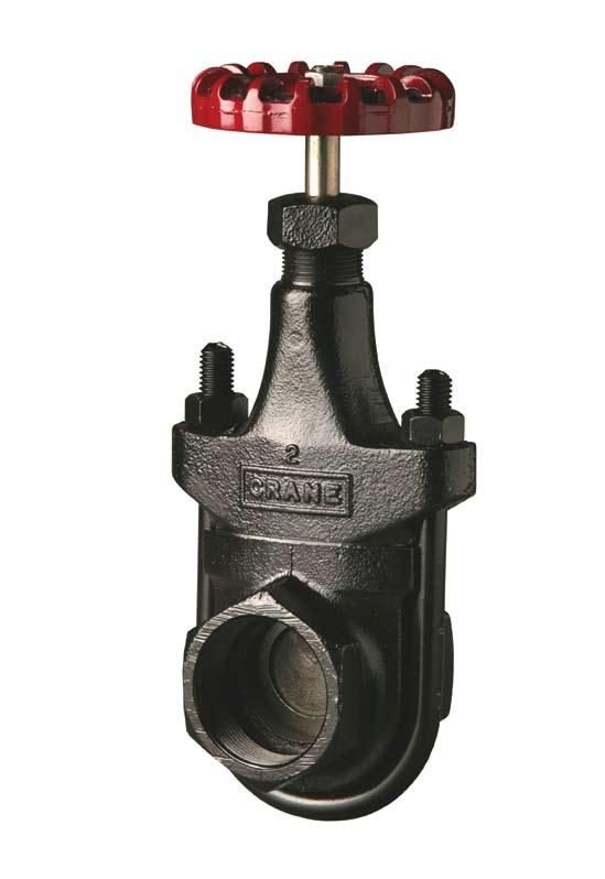
9 Iron Gate Valve Crane gate valves offer the ultimate in dependable service wherever minimum pressure drop is important. They serve as efficient stop valves with fluid flow in either direction. The straight through design offers little resistance to flow and reduces pressure drop to a minimum. disc actuated by a stem and handwheel that moves up and down at right angles to the path of flow, and seats against two seat faces to shut off flow. Gate valves are best for services that require infrequent valve operation, and where disc is kept either fully opened or closed. They are not recommended for throttling. With the usual type of gate valve, close flow regulation is impossible. Velocity of flow against a partly opened disc may cause vibration and chattering and result in damage to the seating surfaces. lso, when throttled, the disc is subjected to severe wire-drawing erosive effects. Each valve in this section is classified by its pressure rating. ll valves, except clamp gate valves, designated as Class 125 and 250 comply with MSS SP-70 Standard Practice. ronze-trimmed valves are recommended for steam, water, air and non-corrosive oil or gas. ll have bronze screwed-in seat rings and the discs are solid bronze in sizes 3" (80 mm) and smaller. In larger sizes, bronze rings are rolled into cast iron discs. Handwheel nut Handwheel Gland Packing nut Packing Stem Upper bonnet Stem thread bushing Lower bonnet ll-iron valves have integral seats, some valves have screwed in seat rings (discs are cast iron) and nickel-plated steel stems. They are recommended for oil, gas, gasoline, or fluids that corrode bronze but not iron or steel. Face-to-Face Dimensions of flanged end valves comply with MSS SP-70, conform to SME in their pressure class. Flanged End Valves adhere to SME Specification 16.1 for their pressure class. ody and onnet Components are cast with rigorous control to STM 126 Class Specification for cast-iron. Malleable iron, Ni-resist and 3% nickel iron are also available. Handwheels are furnished on all valves. Manual gear, hydraulic or motor operators and chainwheels can be supplied when specified. ackseating - Rising stem valves are equipped with backseats. It is recommended that the backseat be used as a means for determining the full open valve position. For normal operation in the open position, the stem should be backed off so that the Handwheel nut Handwheel Yoke sleeve Stem Gland bolt nut Gland Packing onnet onnet bolt onnet gasket onnet nut backseat is not in contact. This permits the stem packing to assume its intended sealing function and not conceal unsatisfactory stem packing. In the event of stem packing leakage, the backseat can be used to stop stem leakage until circumstances permit a system shutdown and time for packing replacement. Stem packing replacement with the valve under pressure and backseated represents a hazard and should not be undertaken. The hazard is magnified as fluid pressure or temperature increases or when the fluid is toxic. Solid Wedge Gate Valve Discs - The strong, simple, single piece design with long disc guides is a proven performer for all service conditions, particularly suitable for conditions of severe turbulence and stem vibration. Seat and disc surfaces are accurately machined and tapered for shutoff without undue strain. Threaded End Valves have precision cut threads in accordance with SME Crane Iron Gate Valves have an identification tag which indicates the valve catalog number and other pertinent data. It provides easy and accurate field reference. Handwheel nut Handwheel Stem Gland bolt nut Gland Packing Stuffing box Stuffing box gasket onnet onnet bolt onnet gasket onnet nut ody seat ring Disc Disc Clamp Disc seat ring Disc ody seat ring ody Disc seat ring Disc ody seat ring ody -9-
10 Figure 460 Iron ody Gate Valve Class 125 Non-Rising Stem C Figure 460 Threaded with ronze Trim 2 through 4 inches Working Pressures Non-Shock 125 psi Steam, asic Rating 200 psi Cold Working Pressure Tapered Solid Wedge Disc ody Guide Ribs Renewable ronze Seat Rings Stem with CME Double Threads Non-sbestos Packing and Gaskets MSS-SP-70 Type 1 and MSS-SP-25 SME refer to page 9. Fig. No. Size Stem Seating End Conn " - 4" ronze ronze Threaded Valves 2 2 1/2 3 4 (50) (65) (80) (100) (137) (168) (178) (203) (287) (315) (337) (414) C (203) (203) (203) (254) Wt (11.3) (14.0) (20.0) (32.2) -10-
11 Iron ody Gate Valve Figure 461 Class 125 Non-Rising Stem Tapered Solid Wedge Disc ody Guide Ribs Renewable ronze Seat Rings Stem provided with CME Double Threads for valves 24" and smaller; CME Single Thread for 30" valves. Non-sbestos Packing and Gaskets MSS-SP-70 Type 1 and MSS-SP-25 SME 16.10, SME 16.1 Valves can be equipped with by-passes when specified. refer to page 9. Figure 461 Flanged with ronze Trim 2 through 30 inches Working Pressures Non-Shock 2" 12" 125 psi Steam, asic Rating 200 psi Cold Working Pressure 14" 24" 100 psi Steam, asic Rating 150 psi Cold Working Pressure 30" 50 psi Steam, asic Rating 150 psi Cold Working Pressure C Fig. No. Size Stem Seating End Conn " - 30" ronze ronze Flanged Valves 2 2 1/ (50) (65) (80) (100) (125) (150) (200) (250) (300) (350) (400) (450) (500) (600) (750) (178) (191) (203) (229) (254) (267) (292) (330) (356) (381) (406) (432) (457) (508) (610) (287) (315) (337) (414) (457) (526) (613) (838) (927) (1029) (1184) (1289) (1425) (1625) (2200) C (203) (203) (203) (254) (254) (305) (356) (508) (508) (508) (559) (559) (610) (762) (762) Wt (13.6) (18.1) (25.4) (41.0) (57.2) (69.0) (118) (215) (308) (439) (613) (772) (994) (1430) (2728) -11-
12 Figure 473 Iron ody Gate Valve Class 125 Non-Rising Stem C Figure 473 Flanged ll Iron 2 through 8 inches Working Pressures Non-Shock 200 psi Cold Working Pressure Tapered Solid Wedge Disc ody Guide Ribs Integral Seats Stem with CME Double Threads Non-sbestos Packing and Gaskets MSS-SP-70 Type 1 and MSS SP-25 SME 16.10, SME 16.1 Valves can be equipped with by-passes when specified. refer to page 9. Fig. No. Size Stem Seating End Conn " - 8" Steel Iron Flanged Nickel plated Valves 2 2 1/ (50) (65) (80) (100) (150) (200) (178) (191) (203) (229) (267) (292) (287) (315) (337) (414) (526) (613) C (203) (203) (203) (254) (305) (356) Wt (13.6) (18.1) (25.4) (41.0) (69.0) (118) -12-
13 Iron ody Gate Valve Figure Class 125 Outside Screw & Yoke Rising Stem Tapered Solid Wedge Disc ody Guide Ribs Renewable ronze Seat Rings Stem with CME Double Threads Non-sbestos Packing and Gaskets MSS-SP-70 Type 1 and MSS-SP-25 SME Figure Threaded with ronze Trim 2 through 4 inches Working Pressures Non-Shock 125 psi Steam, asic Rating 200 psi Cold Working Pressure C refer to page 9. Open Fig. No. Size Stem Seating End Conn " - 4" ronze ronze Threaded Valves 2 2 1/2 3 4 (50) (65) (80) (100) (137) (168) (178) (203) (375) (408) (441) (545) C (203) (203) (203) (254 Wt (11.3) (17.2) (20.9) (35.0) -13-
14 Figure Iron ody Gate Valve Class 125 Outside Screw & Yoke Rising Stem C Open Figure Flanged with ronze Trim 2 through 36 inches Working Pressures Non-Shock 2" 12" 125 psi Steam, asic Rating 200 psi Cold Working Pressure 14" 24" 100 psi Steam, asic Rating 150 psi Cold Working Pressure 30" 36" 50 psi Steam, asic Rating 150 psi Cold Working Pressure Tapered Solid Wedge Disc ody Guide Ribs Renewable ronze Seat Rings Stem provided with CME Double Threads for 24" and smaller valves; CME Single Thread for 30" and 36" valves. Non-sbestos Packing and Gaskets MSS-SP-70 Type 1 and MSS-SP-25 SME 16.10, SME 16.1 Valves can be equipped with by-passes when specified. refer to page 9. Fig. No. Size Stem Seating End Conn " - 36" ronze ronze Flanged Valves 2 2 1/ (50) (65) (80) (100) (125) (150) (200) (250) (300) (350) (400) (450) (500) (600) (750) (900) (178) (191) (203) (229) (254) (267) (292) (330) (356) (381) (406) (432) (457) (508) (610) (711) (375) (408) (441) (545) (656) (770) (959) (1255) (1443) (1648) (1910) (2083) (2291) (2675) (3292) (4894) C (203) (203) (203) (254) (254) (305) (356) (457) (457) (508) (559) (559) (610) (762) (762) (762) Wt (13.6) (21.3) (26.3) (44.0) (56.7) (73.6) (127.2) (228) (304) (496) (646) (788) (946) (1444) (2629) (3457) -14-
15 Iron ody Gate Valve Figure Class 125 Outside Screw & Yoke Rising Stem Tapered Solid Wedge Disc ody Guide Ribs 2"-8" Integral Seats, 10" and larger Renewable Cast Iron Seat Rings Stem provided with CME Double Threads for 24" and smaller valves; CME Single Thread for 30" and 36" valves. Non-sbestos Packing and Gaskets MSS-SP-70 Type 1 and MSS-SP-25 SME 16.10, SME 16.1 Valves can be equipped with by-passes when specified. refer to page 9. Figure Flanged ll Iron 2 through 36 inches Working Pressures Non-Shock 2" 12" 200 psi Cold Working Pressure 14" 36" 150 psi Cold Working Pressure C Open Fig. No. Size Stem Seating End Conn " - 36" Steel Iron Flanged Nickel Plated Valves 2 2 1/ (50) (65) (80) (100) (125) (150) (200) (250) (300) (350) (400) (450) (500) (600) (750) (900) (178) (191) (203) (229) (254) (267) (292) (330) (356) (381) (406) (432) (457) (508) (610) (711) (375) (408) (441) (545) (656) (770) (959) (1255) (1443) (1648) (1910) (2083) (2291) (2675) (3292) (4894) C (203) (203) (203) (254) (254) (305) (356) (457) (457) (508) (559) (559) (610) (762) (762) (762) Wt (13.6) (21.3) (26.3) (44.0) (56.7) (73.6) (127.2) (228) (304) (496) (646) (788) (946) (1444) (2629) (3457) -15-
16 Figure 488 Iron ody Gate Valve Class Clamp Gate Inside Screw Rising Stem C Open Figure 488 Threaded - ll Iron 1/4 through 4 inches Compact Design Easy Maintenance Steel U-olt Clamp nti-clogging onnet Integral Seats Malleable Iron Disc Nickel Plated Steel Stem Non-sbestos Packing & Gaskets ody and onnet Malleable Iron SME Every valve is individually tested refer to page 9. TEMPERTURE Valve Ratings WORKING PRESSURES, NON-SHOCK 1/4" - 2" 2 1/2" to 4" (6mm to 50mm) (65mm to 100mm) 225 psi, CWP 175 psi, CWP F C PSI kpa PSI kpa -20 to to Fig. No. Size Stem Seating End Conn /4" - 4" Steel Iron Threaded Nickel Plated Valves 1/4 3/8 1/2 3/ /4 1 1/ /2 3 4 (6) (10) (15) (20) (25) (32) (40) (50) (65) (80) (100) 3.00* 3.00* (76.2) (76.2) (52) (59) (65) (73) (80) (92) (105) (116) (141) (129) (129) (129) (157) (188) (226) (253) (295) (328) (390) (502) C (52) (52) (52) (65) (70) (78) (92) (103) (121) (152) (229) Wt (0.84) (0.84) (0.84) (1.09) (1.59) (2.63) (3.17) (5.08) (8.71) (10.47) (23.61) *Includes Hexagon ushings in each end. -16-
17 Iron ody Gate Valve Figure Class 125 Clamp Gate Inside Screw Rising Stem Compact Design Easy Maintenance Steel U-olt Clamp nti-clogging onnet Integral Seats Malleable Iron Disc Nickel Plated Steel Stem Non-sbestos Packing & Gaskets ody and onnet Malleable Iron SME 16.1 Every valve is individually tested refer to page 9. Figure Flanged - ll Iron 1 through 4 inches C Open TEMPERTURE Valve Ratings WORKING PRESSURES, NON-SHOCK 1" to 2" 2 1/2" to 4" (25mm to 50mm) (65mm to 100mm) 200 psi, CWP 175 psi, CWP F C PSI kpa PSI kpa -20 to to Fig. No. Size Stem Seating End Conn " - 4" Steel Iron Flanged Nickel Plated Valves 1 1 1/ /2 3 4 (25) (40) (50) (65) (80) (100) (81) (95) (108) (125) (129) (172) (188) (253) (295) (328) (390) (502) C (70) (92) (103) (121) (152) (229) Wt (2.49) (4.71) (6.48) (9.97) (14.50) (27.19) -17-
18 Figure 490 Iron ody Gate Valve Class Clamp Gate Inside Screw Rising Stem C Open Figure 490 Threaded - ronze Trim 1/4 through 4 inches Compact Design Easy Maintenance Steel U-olt Clamp nti-clogging onnet ronze Seat Rings Non-sbestos Packing & Gaskets ody and onnet Malleable Iron SME ronze Disc Every valve is individually tested refer to page 9. TEMPERTURE Valve Ratings WORKING PRESSURES, NON-SHOCK 1/4" to 2" 2 1/2" to 4" (6mm to 50mm) (65mm to 100mm) 150 psi, Sat. Steam 125 psi, Sat. Steam 225 psi, CWP 175 psi, CWP F C PSI kpa PSI kpa -20 to to Fig. No. Size Stem Seating End Conn /4" - 4" ronze ronze Threaded Valves 1/4 3/8 1/2 3/ /4 1 1/ /2 3 4 (6) (10) (15) (20) (25) (32) (40) (50) (65) (80) (100) 3.00* 3.00* (76.2) (76.2) (52) (59) (65) (73) (80) (92) (105) (116) (141) (129) (129) (129) (157) (188) (226) (253) (295) (328) (390) (502) C (52) (52) (52) (65) (70) (78) (92) (103) (121) (152) (229) Wt (0.84) (0.84) (0.84) (1.08) (1.59) (2.63) (3.17) (5.08) (8.71) (10.47) (23.61) *Includes Hexagon ushings in each end. -18-
19 Clamp Gate Valve Figure Class 125 Outside Screw & Yoke Threaded Ends Compact Design Easy Maintenance Steel U-olt Clamp Integral Seats Malleable Iron Disc Nickel Plated Steel Stem Non-sbestos Packing & Gasket ody and onnet Malleable Iron SME Every valve is individually tested refer to page 9. Figure Threaded - ll Iron 1/2 through 3 inches C TEMPERTURE WORKING PRESSURES, NON-SHOCK 1/2" to 2" 2 1/2" to 3" Valve (12mm to 50mm) (65mm to 75mm) Ratings 225 psi, CWP 175 psi, CWP F C PSI kpa PSI kpa -20 to to Fig. No. Size Stem Seating End Conn /2" - 3" Steel Iron Threaded Nickel Plated Valves 1/2 3/ /4 1 1/ /2 3 (15) (20) (25) (32) (40) (50) (65) (80) (52) (59 ) (65) (73) (80) (92) (105) (116) (171) (191) (235) (260) (311) (368) (419) (483) C (65) (65) (70) (78) (92) (103) (121) (152) Wt (0.91) (1.81) (2.26) (2.72) (4.31) (6.12) (9.30) (13.38) -19-
20 Figure Malleable Iron Clamp Gate Valve Class 125 Outside Screw & Yoke Flanged Ends C Figure Flanged - ll Iron 1-1/2 through 4 inches Compact Design Easy Maintenance Steel U-olt Clamp Integral Seats Malleable Iron Disc Nickel Plated Steel Stem Non-sbestos Packing & Gasket ody and onnet Malleable Iron SME 16.1 Every valve is individually tested refer to page 9. Open TEMPERTURE Valve Ratings WORKING PRESSURES, NON-SHOCK 1 1/2" to 2" 2 1/2" to 4" (40mm to 50mm) (65mm to 100mm) 200 psi, CWP 175 psi, CWP F C PSI kpa PSI kpa -20 to to Fig. No. Size Stem Seating End Conn /2" - 4" Steel Iron Flanged Nickel Plated Valves 1 1/ /2 3 4 (40) (50) (65) (80) (100) (95) (108) (125) (129) (171) (311) (368) (419) (483) (610) C (92) (103) (121) (152) (229) Wt (6.58) (8.84) (14.06) (18.14) (34.01) -20-
21 Malleable Iron Clamp Gate Valve Class 125 Outside Screw & Yoke Threaded Ends Figure Compact Design Easy Maintenance Steel U-olt Clamp ronze Seat Rings ronze Disc Non-sbestos Packing & Gasket ody and onnet Malleable Iron SME Every valve is individually tested refer to page 9. Figure Threaded - ronze Trim 1/2 through 2 inches C TEMPERTURE Valve Ratings WORKING PRESSURES, NON-SHOCK 1/2" to 2" (12mm to 50mm) 150 psi, Sat. Steam 225 psi, CWP F C PSI kpa -20 to to Open Fig. No. Size Stem Seating End Conn /2" - 2" ronze ronze Threaded Valves 1/2 3/ /4 1 1/2 2 (15) (20) (25) (32) (40) (50) (52) (59) (65) (73) (80) (91) (171) (191) (235) (260) (311) (368) C (65) (65) (70) (78) (92) (103) Wt (0.91) (1.81) (2.00) (3.21) (4.31) (5.49) -21-
22 Figure Malleable Iron Clamp Gate Valve Class 125 Outside Screw & Yoke Flanged Ends C Figure Flanged - ronze Trim 1-1/2 through 4 inches Compact Design Easy Maintenance Steel U-olt Clamp ronze Seat Rings ronze Disc Non-sbestos Packing & Gasket ody and onnet Malleable Iron SME 16.1 Every valve is individually tested refer to page 9. Open TEMPERTURE Valve Ratings WORKING PRESSURES, NON-SHOCK 1 1/2" to 2" 2 1/2" to 4" (40mm to 50mm) (65mm to 100mm) 125 psi, Sat. Steam 125 psi, Sat. Steam 200 psi, CWP 175 psi, CWP F C PSI kpa PSI kpa -20 to to Fig. No. Size Stem Seating End Conn /2" - 4" ronze ronze Flanged Valves 1 1/ /2 3 4 (40) (50) (65) (80) (100) (95) (108) (125) (129) (171) (311) (368) (419) (485) (510) C (92) (103) (121) (152) (229) Wt (5.90) (7.71) (14.06) (18.14) (34.01) -22-
23 Iron ody Gate Valve Figure 3E Class 250 Non-Rising Stem Flanged Ends Tapered Solid Wedge Disc ody Guide Ribs Renewable ronze Seat Rings Non-sbestos Packing & Gaskets Valves can be equipped with bypasses when specified Valves 6" and larger have bosses cast into the bodies and bonnets, and can be equipped with taps and drains to prevent fluids from accumulating and possibly causing damage. Orders must specify location of taps and drains. Stem with CME Double Threads MSS-SP-70 Type 1 and MSS-SP-25 SME 16.10, SME 16.1 Figure 3E Flanged with ronze Trim 2 through 12 inches Working Pressures Non-Shock 250 psi Steam, asic Rating 500 psi Cold Working Pressure C refer to page 9. Fig. No. Size Stem Seating End Conn. 3E 2" - 12" ronze ronze Flanged Valves 2 2 1/ (50) (65) (80) (100) (150) (200) (250) (300) (216) (241) (282) (305) (403) (419) (457) (502) (303) (329) (368) (441) (584) (781) (914) (1010) C (203) (229) (254) (305) (406) (508) (559) (610) Wt (21) (38) (51) (80) (152) (247) (386) (590) -23-
24 Figure 7 1 2E Iron ody Gate Valve Class 250 Outside Screw & Yoke Rising Stem C Open Figure 7 1 2E Flanged with ronze Trim 2 through 12 inches Working Pressures Non-Shock 250 psi Steam, asic Rating 500 psi Cold Working Pressure Tapered Solid Wedge Disc ody Guide Ribs Non sbestos Packing and Gaskets ronze Stem Renewable ronze Seat Rings CME Double Stem Threads Valves can be equipped with bypasses when specified. Valves 6" and larger have bosses cast into the bodies and bonnets, and can be equipped with taps and drains to prevent fluids from accumulating and possibly causing damage. Orders must specify location of taps and drains. MSS-SP-70 Type 1 and MSS-SP-25 SME 16.10, SME 16.1 refer to page 9. Fig. No. Size Stem Seating End Conn E 2" - 12" ronze ronze Flanged Valves 2 2 1/ (50) (65) (80) (100) (125) (150) (200) (250) (300) (216) (241) (282) (305) (381) (403) (419) (457) (502) (383) (424) (476) (595) (756) (806) (1012) (1378) (1595) C (203) (229) (254) (305) (356) (406) (508) (559) (610) Wt (24) (36) (52) (79) (127) (150) (272) (418) (636) -24-
25 Iron Globe and ngle Valve Crane globe and angle valves are highly efficient for throttling service because disc and seat designs provide flow characteristics with proportionate relationships between valve lift and flow rate. This assures accurate regulated flow control. The additional advantage of an angle valve is that it provides a 90 turn in piping so fewer joints are required and make-up time and labor are reduced. ody and onnet are normally cast of Crane High Strength Cast conforming to STM 126, Class. Malleable Iron valves are available for higher pressures. Two types of bonnet construction are available: Union onnet gives added strength and rigidity to the body to withstand internal pressure and distortion. ecause it is easy to dismantle, it is used on smaller valves requiring frequent inspection or cleaning. olted onnet is the most common design because there is practically no limitation on size. Multiple bolting permits equalized sealing pressure on the gasket against the highest pressures encountered in iron globe and angle valve applications. ll bolted bonnet valves in this section comply with MSS SP-85 standard practice. There are two types of discs supplied in Crane globe and angle valves: Metal Disc in most valves is fully guided throughout its travel, minimizing vibration of internal parts and assuring true seating. The disc stem connection is designed to securely hold the disc yet permit swivel action. Disc materials are iron, bronze, iron faced with bronze, steel or a nickel alloy. Metal Plug Disc is conically shaped. This design is universally accepted for rigorous service. ecause of the wide seating surfaces, it is not easily harmed by foreign matter or wiredrawing. Crane uses stainless steel in this design. Seats are screwed in and can be reground or replaced whenever necessary. Stem material is matched to service recommendations for improved operating dependability and life. Packing non-asbestos rings. ackseating: Rising stem valves are equipped with backseats. It is recommended that the backseat be used as a means for determining the full open valve position. For normal operation in the open position, the stem should be backed off so that the backseat is not in contact. This permits the stem packing to assume its intended sealing function and not conceal unsatisfactory stem packing. In the event of stem packing leakage, the backseat can be used to stop stem leakage until circumstances permit a system shutdown and time for packing replacement. Stem packing replacement with the valve under pressure and backseated represents a hazard and should not be undertaken. The hazard is magnified as fluid pressure or temperature increases or when the fluid is toxic. Handwheels are furnished on all valves. Manual gear, hydraulic or motor operators and chainwheels can be supplied when specified. Face-to-Face Dimensions of flanged end valves conform to SME in their pressure class. Flanged End Valves adhere to SME specification 16.1 for their pressure class. Handwheel nut Handwheel Yoke bushing Stem Gland flange Gland onnet & yoke Packing Stem hole bushing ody Disc stem ring Locking washer Disc ody seat ring Handwheel nut Handwheel Stem Gland nut Gland Packing onnet onnet nut Plug ody seat ring ody OLTED ONNET, FLNGED UNION ONNET, THRED -25-
26 Figure 351 Iron ody Globe Valve Class 125 Outside Screw & Yoke Rising Stem C Open Figure 351 Flanged with ronze Trim 2 through 10 inches Working Pressures Non-Shock 125 psi Steam, asic Rating 200 psi Cold Working Pressure Integral Yoke onnet with upper and lower bronze bushing provides for centering of internal parts Non Galling Two-Piece Packing Gland Valves are provided with a ack Seat Renewable - Regrindable Screwedin Seat Ring ottom Guided Disc Manganese ronze Stem Non-sbestos Packing & Gasket Solid ronze Disc 6" and smaller SME 16.1, SME MSS-SP-85 Type 1 and MSS-SP-25 refer to page 25. Fig. No. Size Stem Seating End Conn " - 10" ronze ronze Flanged Valves 2 2 1/ (50) (65) (80) (100) (125) (150) (200) (250) (203) (216) (241) (292) (330) (356) (495) (622) (282) (292) (337) (394) (445) (495) (635) (775) C (203) (203) (229) (254) (254) (305) (406) (508) Wt (15) (18) (26) (43) (57) (80) (156) (259) -26-
27 Iron ody Globe Valve Figure 21E Class 250 Outside Screw & Yoke Rising Stem Integral Yoke onnet Non Galling Two-Piece Packing Gland ronze Seat Ring, STM 61 Disc Stem Ring Manganese ronze Stem Non-sbestos Packing and Gasket Valves are provided with a ack Seat Renewable - Regrindable, Screwed-in Seat Ring ottom Guided Disc Solid ronze Disc, STM 61-3" and smaller. 4" and larger cast iron with bronze facing, STM 61 SME 16.1, SME MSS-SP-85 Type 1 and MSS-SP-25 Figure 21E Flanged - ronze Trim 2 through 8 inches Working Pressures Non-Shock 250 psi Steam, asic Rating 500 psi Cold Working Pressure refer to page 25. Fig. No. Size Stem Seating End Conn. 21E 2" - 8" ronze ronze Flanged Valves 2 2 1/ (50) (65) (80) (100) (150) (200) (267) (292) (318) (356) (445) (533) (349) (375) (419) (470) (591) (724) C (229) (254) (254) (305) (406) (508) Wt (28) (37) (54) (76) (145) (259) -27-
28 Figure 254XR Malleable Iron Globe Valve 700 SWP/1000 CWP Rising Stem Threaded Ends C Figure 254XR Threaded with 13% Chromium Nickel lloy 1/2 through 2 inches Union onnet Valves are provided with a backseat Malleable Iron ody and onnet ll sizes are air tested Disc - Nickel lloy Seat Ring - 13% Chromium Stainless Steel Stem - 13% Chromium Stainless Steel SME refer to page 25. Open Temperature Working Pressure F Non-Shock, psi Fig. No. Size Stem Seating End Conn. 254XR 1/2" - 2" 13 CR. SS Nickel lloy Threaded Valves 1/2 3/ /4 1 1/2 2 (15) (20) (25) (32) (40) (65) (71) (84) (99) (112) (125) (152) (133) (135) (171) (195) (219) (249) C (65) (70) (78) (92) (103) (121) Wt (0.77) (1.13) (1.72) (2.68) (3.62) (5.76) -28-
29 Iron ody ngle Valve Figure 353 Class 125 Outside Screw & Yoke Rising Stem Integral Yoke onnet with upper and lower bronze bushings provide for centering of internal parts Non Galling Two-Piece Packing Gland Valves are provided with a ack Seat Renewable - Regrindable Screwed-in Seat Ring ottom Guided Disc Manganese ronze Stem Non-sbestos Packing & Gasket Solid ronze Disc 6" and smaller SME 16.1, SME MSS-SP-85 Type 2 and MSS-SP-25 Figure 353 Flanged - ronze Trim 2 through 6 inches Working Pressures Non-Shock 125 psi Steam, asic Rating 200 psi Cold Working Pressure C Open refer to page 25. Fig. No. Size Stem Seating End Conn " - 6" ronze ronze Flanged Valves 2 2 1/ (50) (65) (80) (100) (150) (102) (109) (121) (146) (178) (279) (292) (324) (381) (495) C (203) (203) (229) (254) (304) Wt (15) (17) (25) (40) (72) -29-
30 Iron Check Valve Check valves permit flow in one direction only and close automatically when flow reverses. They are entirely automatic in action, depending upon pressure and velocity of flow within the line to perform their functions of opening and closing. The disc and any associated moving parts may be in a constant state of movement if the velocity pressure is not sufficient to hold the disc in a wide open and stable position. Premature wear and noisy operation or vibration can be avoided by selecting the size of the check valve on the basis of flow conditions rather than selecting the check valve according to the size of the pipeline. Sizing check valves on this basis may often result in the use of valves that are smaller than the pipe in which they are used, necessitating the use of reducers for installation. The pressure drop will be no greater than that of a larger valve that is partially open. Valve life will be greatly extended, and the added bonus, of course, is the lower cost of the smaller valves. Each valve in this section is classified by its pressure rating. ll swing check valves designated as Class 125 and 250 comply with MSS SP-71 Standard Practice. Tilting Disc Check Valves are similar in application to swing check valves. Essentially, the tilting disc check valve consists of a cylindrical housing with a pivoted circular disc. The pivots are located just above the center of the disc and offset from the plane of the body seat. This design decreases the travel distance of the disc, and the closing force due to reversal of flow and pressure differential is reduced by pivot location, thereby minimizing slam. The seat is of a circular bevel type and the disc pivots in or out of contact without rubbing or sliding, while full pressure differential acts to seal the disc tightly after seating. Swing Check Valves with straight-through body design and wide hinge support provide turbulence-free flow and accurate seating. There is no tendency for seating surfaces to gall or score because the disc meets the flat seat squarely without rubbing. When faster reaction to flow reversal is necessary, certain valves can be equipped with an outside lever and weight. This will assist the disc to close more rapidly and reduce the possibility of surge and shock. Crane Iron Check Valves have an identification tag which indicates the valve catalog number and other pertinent data. It provides easy and accurate field reference. Threaded Ends in accordance with SME Flanged Swing Check Valves conform to applicable requirements of SME in sizes 2" through 14". Flanged valves conform to applicable requirements of 16.1 for Class 125 and 250 cast iron swing check valves. ronze Trim Valves are for steam, water, non-corrosive oil and gas and other fluids that do not corrode bronze. ll Iron Valves are for gases, oils and other fluids not corrosive to iron. Valves May e Installed in horizontal or vertical pipe lines. In vertical lines, or any angle from horizontal, they can be used for upward flow only. Non-sbestos Gaskets and Packings. ody Hinge pin Cap Cap gasket Cap bolt nuts Hinge pin Cap bolts Identification plate Hinge Disc washer Disc nut Disc ody ody seat ring Disc ody TILTING DISC SWING CHECK -30-
31 Iron ody Swing Check Valve Figure 372 Class 125 olted Cap Threaded Ends Design prohibits galling or scoring of seating surfaces because the disc meets the flat seat squarely on closing with no rubbing action Replaceable ronze Seat Rings ronze Hinges Solid ronze Disc Large olted-on Cover Replaceable rass Hinge Pin ushings SME , MSS-SP-71 Type 1 and MSS-SP-25 Figure 372 Threaded with ronze Trim 2 through 4 inches Working Pressures Non-Shock 125 psi Steam, asic Rating 200 psi Cold Working Pressure refer to page 30. Fig. No. Size Seating End Conn " - 4" ronze Threaded Valves 2 2 1/2 3 4 (50) (65) (80) (100) (155) (184) (202) (235) (114) (137) (149) (168) Wt (8) (10) (13) (24) -31-
32 Figure 373 Iron ody Swing Check Valve Class 125 olted Cap Flanged Ends Figure 373 Flanged with ronze Trim 2 through 24 inches Working Pressures Non-Shock 2"-12" 125 psi Steam, asic Rating 200 psi Cold Working Pressure 14"-24" 100 psi Steam, asic Rating 150 psi Cold Working Pressure Design prohibits galling or scoring of seating surfaces because the disc meets the flat seat squarely on closing with no rubbing action Replaceable ronze Seat Rings ronze Hinges in 6" and smaller, ductile iron in larger sizes Large olted-on Cover Solid ronze Disc 6" and smaller, ronze Faced Cast Iron on larger sizes Replaceable rass Hinge Pins SME 16.1, MSS-SP-71 Type 1 and MSS-SP-25 SME " and smaller refer to page 30. Fig. No. Size Seating End Conn " - 24" ronze Flanged Valves 2 2 1/ (50) (65) (80) (100) (125) (150) (200) (250) (300) (350) (400) (450) (500) (600) (203) (216) (241) (292) (330) (356) (495) (622) (699) (787) (914) (965) (1067) (1169) (114) (137) (149) (168) (197) (210) (260) (305) (349) (406) (457) (610) (700) (787) Wt (11) (15) (20) (34) (47) (58) (104) (200) (299) (435) (658) (864) (1149) (1529) -32-
33 Iron ody Swing Check Valve Figure Class 125 olted Cap Flanged Ends Design prohibits galling or scoring of seating surfaces because the disc meets the flat seat squarely on closing with no rubbing action Large olted On Cover Hinges are Ductile Iron Integral ody Seats 8" and smaller Replaceable 13% Chromium Stainless Steel Hinge Pins Replaceable Hinge Pin ushings Disc is Solid Iron with Integral Seat Face SME 16.1, SME MSS-SP-71 Type 1 and MSS-SP-25 Figure Flanged, ll Iron Trim 2 through 12 inches Working Pressure Non-Shock 200 psi Cold Working Pressure refer to page 30. Fig. No. Size Seating End Conn " - 12" ll iron Flanged Valves 2 2 1/ (50) (65) (80) (100) (125) (150) (200) (250) (300) (203) (216) (241) (292) (330) (356) (495) (622) (699) (114) (137) (149) (168) (197) (210) (260) (305) (349) Wt (11) (15) (20) (34) (47) (58) (104) (200) (299) -33-
34 Figure 383 Iron ody Swing Check Valve Class 125 olted Cap Flanged Ends Figure 383 Flanged, outside lever and weight with bronze trim 2 through 24 inches Working Pressure Non-Shock 2" - 12" 125 psi Steam, asic Rating 200 psi Cold Working Pressure 14" - 24" 100 psi Steam, asic Rating 150 psi Cold Working Pressure Design prohibits galling or scoring of seating surfaces because the disc meets the flat seat squarely on closing with no rubbing action Large olted On Cover Fig. 383 with outside lever and weight is recommended where quick action is necessary to avoid sudden reversal of flow. Weight can be installed to balance the disc when applications require that it open under minimum pressure. Positioning and setting of lever and weight are easily accomplished in the field. Lever can be rotated through 360 and is adjustable in 15 increments. Valves may be installed in horizontal or vertical pipe lines for upward flow. asic design of Fig. 383 identical to Fig Solid ronze Disc 6" and smaller; ronze Faced in 8" and larger. Replaceable Stainless Steel Hinge pins. Solid ronze Hinge 6" and smaller; Ductile Iron for 8" and larger. refer to page 30. Fig. No. Size Seating End Conn " - 24" ronze Flanged Valves 2 2 1/ (50) (65) (80) (100) (150) (200) (250) (300) (350) (400) (450) (500) (600) (203) (216) (241) (292) (356) (495) (622) (699) (787) (914) (965) (1067) (1169 ) (114) (137) (149) (168) (210) (260) (305) (349) (429) (484) (610) (700) (787) Wt Data on larger sizes (14) (18) (24) (38) (62) (109) (215) (322) available on request -34-
35 Iron ody Swing Check Valve Figure 39E Class 250 olted Cap Flanged Ends For steam, water, oil, gas and similar high pressure-temperature conditions which do not warrant steel valves. Valves can be installed horizontally, or vertically for upward flow. High-Strength Cast Iron ody and Cap conforms to STM 126, Class. Solid ronze Disc in 3" and smaller; ronze-faced Iron Disc in 4" and larger. Screwed-in ronze ody Seat Ring Disc moves freely for maximum flow with minimum pressure drop. disc stop, integral with the cap, prohibits the disc from sticking open when flow is reversed. SME 16.1, SME MSS-SP-71 Type 1 and MSS SP-25 Figure 39E Flanged - ronze Trim 2 through 8 inches Working Pressures Non-Shock 250 psi Steam, asic Rating 500 psi Cold Working Pressure refer to page 30. Fig. No. Size Seating End Conn. 39E 2" - 8" ronze Flanged Valves 2 2 1/ (50) (65) (80) (100) (150) (200) (267) (292) (318) (356) (445) (533) (133) (152) (159) (184) (229) (279) Wt (21) (29) (41) (60) (114) (186) -35-
36 Figure Malleable Iron Swing Check Valve 700 SWP/1000 CWP Y-Pattern Threaded Ends Figure Threaded - Malleable Iron 1/2 through 2 inches Malleable Iron ody and Cap Hinge Pin 13% Chromium Stainless Steel SME refer to page 30. Temperature Working Pressure F Non-Shock, psi Fig. No. Size Seating End Conn " - 2" Iron Threaded Valves 1/2 3/ /4 1 1/2 2 (15) (20) (25) (32) (40) (50) (70) (83) (103) (120) (137) (168) (43) (51) (62) (73) (84) (109) Wt (0.43) (0.65) (1.11) (1.30) (2.61) (4.51) -36-
37 Iron ody Stop Check Valve Figure 28E Class 250 Y-Pattern Flanged Ends Straightway Figure 28E Flanged, Y-Pattern with olted onnet Straightway 2-1/2 through 10 inches Working Pressures Non-Shock 250 psi Steam, asic Rating 500 psi Cold Working Pressure For installation between boilers suppling the same steam header, and positioned with pressure under the disc. Straightway is for horizontal or vertical line with upward flow. ngle valves are for "horizontal-downward" or "upward-horizontal" flow. These valves will perform the four following important functions: 1. ct as an automatic-non return valve applied as a containment device to prevent gross backflow of steam from main header to boiler in case the boiler fails. 2. ssist in cutting out boiler, when ceasing to fire. In this case, valve disc automatically closes to restrict backflow of steam to the boiler. 3. ssist in returning boiler after a shutdown. 4. Restricts backflow of steam from header into boiler which has been shut down and accidently opened. The check valve feature should not be relied upon for primary shut-off. Cylindrical shaped disc is the only pressure-actuated part, light in weight with ample guiding surface. It is specially designed to produce a maximum lift at minimum velocities. There are no wing guides to cause "spinning" with resultant rapid wear. Long throttling lip on disc retards flow when seating position is approached. Disc chattering is prevented and wiredrawing of seating surfaces is reduced. Flat Seats, accurately machined, facilitate true seating. Removable cast iron liner guides the disc throughout its full travel. eing entirely independent of the body, it is not subject to distortion by expansion strains. Piston Ring 6" and larger adds to dashpot's ability to avoid rapid disc movements. Where pulsations are extremely severe, two rings can be installed. Dashpot is self-contained in the liner. It provides an effective cushion for the disc to prevent pipe line vibrations or hammering on the seat at low velocities or on pulsating loads. Flanges conform to SME Flanges have 1/16" raised face with concentric grooves. The body has integral bosses for drain connections. The bosses are tapped and plugged. Determining the proper valve size needed is important. The size of a stop check valve should be based on the boiler capacity and steam flow through the valve, rather than on the size of the boiler outlet or existing piping. E Open C Open G Valves 2 1/ (65) (80) (100) (125) (150) (200) (250) (330) (375) (432) (483) (546) (660) (762) C* (127) (184) (197) (267) (298) (413) (451) E* (400) (502) (552) (654) (743) (933) (1060) G (229) (254) (254) (356) (406) (508) (508) Wt (47) (64) (103) (139) (191) (335) (568) -37-
38 Figure 30E Iron ody Stop Check Valve Class 250 Y-Pattern Flanged Ends ngle F Open D Open G Figure 30E Flanged, Y-Pattern with olted onnet ngle 2-1/2 through 10 inches Working Pressures Non-Shock 250 psi Steam, asic Rating 500 psi Cold Working Pressure For installation between boilers suppling the same steam header, and positioned with pressure under the disc. Straightway is for horizontal or vertical line with upward flow. ngle valves are for "horizontal-downward" or "upward-horizontal" flow. These valves will perform the four following important functions: 1. ct as an automatic-non return valve applied as a containment device to prevent gross backflow of steam from main header to boiler in case the boiler fails. 2. ssist in cutting out boiler, when ceasing to fire. In this case, valve disc automatically closes to restrict backflow of steam to the boiler. 3. ssist in returning boiler after a shutdown. 4. Restricts backflow of steam from header into boiler which has been shut down and accidently opened. The check valve feature should not be relied upon for primary shut-off. Cylindrical shaped disc is the only pressure-actuated part, light in weight with ample guiding surface. It is specially designed to produce a maximum lift at minimum velocities. There are no wing guides to cause "spinning" with resultant rapid wear. Long throttling lip on disc retards flow when seating position is approached. Disc chattering is prevented and wiredrawing of seating surfaces is reduced. Flat Seats, accurately machined, facilitate true seating. Removable cast iron liner guides the disc throughout its full travel. eing entirely independent of the body, it is not subject to distortion by expansion strains. Piston Ring 6" and larger adds to dashpot's ability to avoid rapid disc movements. Where pulsations are extremely severe, two rings can be installed. Dashpot is self-contained in the liner. It provides an effective cushion for the disc to prevent pipe line vibrations or hammering on the seat at low velocities or on pulsating loads. Flanges conform to SME Flanges have 1/16" raised face with concentric grooves. The body has integral bosses for drain connections. The bosses are tapped and plugged. Determining the proper valve size needed is important. The size of a stop check valve should be based on the boiler capacity and steam flow through the valve, rather than on the size of the boiler outlet or existing piping Valves 2 1/ (65) (80) (100) (125) (150) (200) (250) (146) (159) (178) (200) (222) (267) (311) D (368) (419) (470) (559) (648) (845) (959) F (337) (375) (413) (495) (572) (730) (826) G (229) (254) (254) (356) (406) (508) (508) Wt (39) (56) (84) (113) (154) (291) (465)
39 olted onnet Stop Check Valve Technical Data Y-Pattern Stop Check Valve Selecting the Proper Size Determining Pressure Drop Since stop-check valves have a floating disc member, it is important the valve be sized to provide full disc lift under flow conditions prevailing during the major portion of the service life. If the valve is too large, the disc will float in a partially open position and may cause fluttering of the disc and rapid wear. Conversely, if the valve is too small, pressure drop will be excessive. The chart on the following page is a graphic presentation of flow data determined by test. Its use offers a simple method of determining the best size stop-check valve, as well as the pressure drop under varying conditions of flow, without any computation. How to Use the Chart Shown on the Following Page Given: Steam Pressure-Temperature psig 450 F Flow Rate...Typical Daily Demand Curve RTE OF FLOW IN POUNDS PER HOUR Find: 100,000 90,000 80,000 70,000 60,000 50,000 40,000 30,000 20,000 10, Midnight Typical Daily Load-Demand Curve 10-Inch Valve 8-Inch Valve 6 M 12 Noon TIME OF DY 6 PM 12 Midnight Valve Catalog No. and the best size for above installation. Solution: 1. Enter the Temperature chart at 450 F. Move vertically upward to the curved line for 250 psi, then horizontally to the right to establish a point on the specific volume scale. From this point, draw a line through the flow rate being investigated (100,000 Lb/H) and establish a point on Index From that point, draw another line through the valve size, for example the 8-inch size, and establish a point on Index 2. Now move horizontally to the diagonal pressure drop line on the right side. Where these lines intersect, the pressure drop is 7.5 psi for the 8-inch, Class 250 globe valve and 8.5 psi for the 8-inch Class 250 angle valve. Chart solutions resulting in a point on Index 2 that falls below the Line - for Class 250 valves indicate the disc will not be fully lifted under the flow conditions used. Operation under such conditions is not recommended but, at times, must be tolerated for short periods during the low loads. 3. Enter the chart where Line - intersects Index 2 for Class 250 valves. Move diagonally upward through the size being investigated (8-inch) and establish a second point on Index 1. From this point, extend a line to the specific volume established in Step 1 and at its intersection with the flow rate line, read 48,000 Lb/H as the minimum flow rate at which the disc will be in the fully lifted position. The pressure drop at this flow rate is 1.9 psi for globe and 2.1 psi for angle valves. 4. Repeat Steps 2 and 3 for other possible valve sizes, tabulate results, and make size selection on basis of pressure drop and duration of partial disc lift considerations. Valve Press Max.Min. Flow Rate for Size Flow rate (100,000 #/Hr.), psi Wide open valve (Inches) Globe ngle #/Hr , , ,000 Dotted lines on Demand Curve indicate minimum flow rates for wide open 8" and 10" valves. 5. The best choice for this example would be the 10" size because pressure drop is much lower and duration of partially lifted disc is only slightly greater than for the 8" size. 6. Pressure drop for any intermediate flow condition can be determined as outlined in Steps 1 and

40 Iron Valves Technical Data Y-Pattern Stop Check Valve Crane olted onnet Stop-Check Valves Selecting the Proper Size Determining Pressure Drop -40-
General Data... 5 Materials... 6 Pressure/Temperature Ratings... 7 C V
 CRNE Iron Valves Iron Valves Index General Data... 5 Materials... 6 Pressure/Temperature Ratings... 7 C V Coefficients... 8 Gate Section... 9 Globe Section... 25 Check Section... 30 Technical Data...
Bronze Valves. Gate Valves Globe Valves Check Valves
 ronze Valves Gate Valves Globe Valves heck Valves ronze Valves Index ross Reference... 2 General Data... 3 Materials... 4 Ratings... 5 Pressure/Temperature Ratings and Flow Data... 6 ronze Valve Selection
brands you trust. CRANE - Cast Steel Valves
 brands you trust. CRANE - Cast Steel Valves Features & Benefits Key Features & Benefits All seat rings are seal welded as standard Quality process fully documented, materials fully traceable Full range
Cast Steel Valves. General Index. Figure Number Index JENKINS -1-
 Cast Valves Cast Valves SINCE 1864 General Index General Data... 2 Materials... 2 Identification... 3 Gate Valve Features... 4, 5 Globe Valve Features... 9, 10 Swing Check Valve Features... 14, 15 Pressure/Temperature
SECTION GENERAL-DUTY VALVES FOR PLUMBING PIPING
 SECTION 220523 - GENERAL-DUTY VALVES FOR PLUMBING PIPING PART 1 - GENERAL 1.1 RELATED DOCUMENTS A. Drawings and general provisions of the Contract, including General and Supplementary Conditions and Division
Cast Steel Valves. Contents Contents. Figure Number Index. Figure Number Cross Reference. Valve Type Class Stockham Jenkins
 Stockham Cast Valves Cast Valves Contents Contents Performance in Any Application...4 How to Specify and Order Valves...4 Installation, Marking and Identification...5 Gate Valves...6 Globe Valves...11
Distributed by: M&M Control Service, Inc brands you trust.
 Distributed by: M&M Control Service, Inc. /stockham.php 800-876-0036 847-356-0566 brands you trust. STOCKHAM - Cast Valves Contents Performance in Any Application...4 How to Specify and Order Valves...4
Aloyco. Corrosion Resistant Valves. The First Name In Corrosion Resistant Valves
 loyco Corrosion Resistant s The First Name In Corrosion Resistant s Stainless Steel s General Index Figure No. Type Pressure Class End Connection Material vailable Size Range Catalog Page 0 Gate, RS 00
Henderson Engineers, Inc. SECTION GENERAL DUTY VALVES FOR PLUMBING PIPING PART 1 - GENERAL REQUIREMENTS
 SECTION 220523 - GENERAL DUTY VALVES FOR PLUMBING PIPING PART 1 - GENERAL REQUIREMENTS 1.1 SUMMARY A. This Section includes general duty valves common to most plumbing piping systems. 1. Special purpose
brands you trust. ALOYCO Corrosion Resistant Stainless Steel Valves
 brands you trust. LOYCO Corrosion Resistant Stainless Steel s Key Features and pplications Key Features and enefits Full material offering including CF8M, CF3M, and CN7M (lloy 20) road pressure classes
Tilting Disc Check Valve
 Figures 123 123½ Tilting heck Valve lass 150 olted ap Figure 123 Figure 123½ utt Weld 2 through 36 inches (50-900 mm) STM 216 Grade W 285 psi @ -20 F to 100 F (20 bar @ -28 to 37 ) of onstruction* Inlet
Michigan State University Construction Standards. GENERAL-DUTY VALVES FOR PLUMBING PIPING Page
 Page 220523-1 SECTION 220523 - PART 1 - GENERAL 1.1 RELATED DOCUMENTS A. Drawings and general provisions of the Contract, including General and Supplementary Conditions and Division 01 Specification Sections,
SECTION GENERAL-DUTY VALVES FOR PLUMBING PIPING
 SUNY GENESEO 220523-1 PART 1 - GENERAL 1.1 RELATED DOCUMENTS A. Drawings and general provisions of the Contract, including General and Supplementary Conditions and Division 01 Specification Sections, apply
Union County Vocational - Technical Schools Scotch Plains, New Jersey
 SECTION 220523 - GENERAL-DUTY VALVES FOR PLUMBING PIPING PART 1 - GENERAL 1.1 SUMMARY A. Section Includes: 1. Brass ball valves. 2. Iron swing check valves. 3. Iron gate valves. 4. Iron globe valves. B.
Michigan State University Construction Standards. GENERAL-DUTY VALVES FOR HVAC PIPING Page
 Page 230523-1 Copyright 2005 by The American Institute of Architects (AIA) Exclusively published and distributed by Architectural Computer Services, Inc. (ARCOM) for the AIA Modified by MSU Physical Plant
Valve Selection. 1. Function and service considerations
 1. Function and service considerations Valve Selection Selection Valves serve the purpose of controlling the fluids in building services piping. Valves are produced in a variety of design types and materials.
brands you trust. ALOYCO Corrosion Resistant Stainless Steel Valves Crane ChemPharma & Energy
 brands you trust. LOYCO Corrosion Resistant Stainless Steel Valves Crane ChemPharma & Energy Key Features and pplications Key Features and enefits Full material offering including CF8M, CF3M, and CN7M
FIGURE NO. VALVE TYPE PRESSURE CLASS CONNECTIONS SIZE RANGE PAGE NO. 28 Stop Check Valve 300 Flanged 3" 10" 30
 Cast Valves General Index Cast Valves Figure Number Index Ordering Information... 2 General Data... 3 Materials... 4 Identification... 5 General Features... 6 Gate Valve Features... 7 NACE Trim Valves...11
SECTION GENERAL-DUTY VALVES FOR PLUMBING PIPING
 PART 1 - GENERAL 1.1 DESCRIPTION OF WORK A. Provide labor, materials, equipment, and services necessary to install valves required to complete the work indicated on drawings. B. ASME Compliance: 1. ASME
Cast Steel Tilting Disc Check Valve
 ast Steel Tilting heck Valve Typical Tilting heck Valve Tilting heck Valves consist of a cylindrical housing, with a pivoted circular disc. The pivots are located just above the center of the disc, and
Cast Steel Valves. General Index. Figure Number Index
 Cast Valves General Index Ordering Information... 2 General Data... 3 Materials... 4 Identification... 5 General Features... 6 Gate Valve Features... 7 NACE Trim Valves... 11 Globe Valve Features... 12
SECTION VALVES
 PART 1 GENERAL 1.1 RELATED DOCUMENTS A. Drawings and general provisions of the Contract, including General and Supplementary Conditions Specification Sections, apply to this Section. B. Related Sections:
Division 23 - HVAC Section Switzerland Beallsville K-12 GENERAL DUTY VALVES FOR HVAC PIPING
 SECTION 23 05 23 GENERAL-DUTY VALVES FOR HVAC PIPING PART 1 - GENERAL 1.1 RELATED DOCUMENTS A. Drawings and General Provisions of the Contract, including General and Supplementary Conditions and Division
1.2 REFERENCES.1 American National Standards Institute (ANSI)/ American Society of Mechanical Engineers (ASME)
/ American Society of Mechanical Engineers (ASME)") Issued 2005/06/01 Section 15111 Valves Bronze Page 1 of 6 PART 1 GENERAL 1.1 RELATED SECTIONS.1 Section 01355 Waste Management and Disposal 1.2 REFERENCES.1 American National Standards Institute (ANSI)/
Issued 2005/06/01 Section 15111 Valves Bronze Page 1 of 6 PART 1 GENERAL 1.1 RELATED SECTIONS.1 Section 01355 Waste Management and Disposal 1.2 REFERENCES.1 American National Standards Institute (ANSI)/
Cast Steel Valves. General Index. Figure Number Index -1-
 Cast Valves General Index Cast Valves Ordering Information... 2 General Data... 3 Materials... 4 Identification... 5 General Features... 6 Gate Valve Features... 7 NACE Trim Valves...11 Globe Valve Features...12
YARWAY HANCOCK Y-PATTERN FORGED STEEL GLOBE STOP VALVES SERIES 4000
 Direct contact and metal-to-metal seating make this Y-pattern globe stop valve ideal for most shut-off applications. FEATURES All valves feature integral Stellite hardfacing on both body and disc seating
SECTION GENERAL-DUTY VALVES FOR HVAC. A. Section includes valves for building services piping.
 SECTION 23 05 23 GENERAL-DUTY VALVES FOR HVAC PART 1 - GENERAL 1.1 SUMMARY A. Section includes valves for building services piping. 1.2 REFERENCES A. AGA Z21.22 (American Gas Association) - Relief Valves
Brown University Revised August 3, 2012 Facilities Design & Construction Standards SECTION HVAC&R VALVES
 SECTION 23 05 23 HVAC&R VALVES PART 1 - GENERAL 1.1 SUMMARY: A. Section includes valves for building services piping. 1.2 GENERAL VALVE APPLICATION REQUIREMENTS: A. Provide valve handle extensions that
Features and Description of Edward Univalve Globe Valves
 Features and Description of Edward Univalve Globe Valves 7. 8. 9. 1 10. 2. 11. 12. 3. 4. 5. 6. 1. Stem has ACME threads, is ground to a fine finish and is hardened to resist wear. 2. Yoke bushing material
YARWAY BLOW-OFF VALVES SEATLESS, HARDSEAT AND UNIT TANDEM
 YRWY LOW-OFF VLVS STLSS, HRDST ND UNIT TNDM Designed for blow-off service in boiler systems with pressures of 36 psig. FTURS GNRL LICTION low-off service in boiler systems to remove dirt, sediment and
Herpteraium SECTION VALVES GENERAL
 SECTION 22 05 23 VALVES GENERAL 1.01 RELATED DOCUMENTS A. Drawings and general provisions of the Contract, including General and Supplementary Conditions and Division 01 Specification Sections, apply to
SECTION GENERAL-DUTY VALVES FOR HVAC PIPING. A. Contents of Division 23, HVAC and Division 01, General Requirements apply to this Section.
 SECTION 23 05 23 PART 1 - GENERAL 1.1 SUMMARY A. Work Included: 1. Gate Valves 2. Balancing Valves 3. Ball Valves 4. Butterfly Valves 5. Swing Check Valves 1.2 RELATED SECTIONS A. Contents of Division
SECTION PLUMBING PIPING VALVES AND ACCESSORIES PART 1 - GENERAL
 SECTION 22 10 10 PLUMBING PIPING VALVES AND ACCESSORIES PART 1 - GENERAL 1.1 RELATED DOCUMENTS: A. The Conditions of the Contract and applicable requirements of Division 1, "General Requirements", and
BOLTED BONNET API 600
 PACIFIC VALVES BOLTED BONNET API 600 By Subject Product Overview...2-4 Gate Valves Major Features...5 Gate Valves Optional Features...6 Materials of Construction: Gate Valves...7 Gate Valves Product Line...8-10
brands you trust. CRANE - Cast Steel Valves Crane ChemPharma & Energy
 brands you trust. CRANE - Cast Steel Valves Features & Benefits Key Features & Benefits All seat rings are seal welded as standard Quality process fully documented, materials fully traceable Full range
Bronze Gate Valves. SECTION 2a. Tel: +44 (0) Fax: +44 (0)
 Fax: +44 (0)") SETION 2a ronze Gate Valves Tel: +44 (0)1695 712800 Fax: +44 (0)1695 712820 Email: sales@hattersley.com export@hattersley.com www.hattersley.com ontents ronze Gate Valves ontents Page Figure Number Index
SETION 2a ronze Gate Valves Tel: +44 (0)1695 712800 Fax: +44 (0)1695 712820 Email: sales@hattersley.com export@hattersley.com www.hattersley.com ontents ronze Gate Valves ontents Page Figure Number Index
A. This Section includes general duty valves common to several HVAC piping systems.
 SECTION 23 05 23 - PART 1 - GENERAL 1.1 RELATED DOCUMENTS A. Drawings and general provisions of the Contract, including General and Supplementary Conditions and Division 01 Specification Sections, apply
Series Direct contact and metal-to-metal seating makes the T-pattern globe stop valve ideal for most shut-off applications.
 7 YARWAY Hancock T-Pattern Globe valves Direct contact and metal-to-metal seating makes the T-pattern globe stop valve ideal for most shut-off applications Features Heavy integral stellite hardfacing on
SECTION COMMON WORK RESULTS FOR FIRE SUPPRESSION. A. Pipe, fittings, valves, and connections for sprinkler systems.
 SECTION 210500 - COMMON WORK RESULTS FOR FIRE SUPPRESSION PART 1 GENERAL 1.1 SECTION INCLUDES A. Pipe, fittings, valves, and connections for sprinkler systems. 1.2 RELATED REQUIREMENTS A. Section 099000
DARTMOUTH COLLEGE DESIGN January 3, 2012 & CONSTRUCTION GUIDELINES
 SECTION 15100 VALVES PART 1 DESIGN DIRECTIVE 1.1 SUMMARY A. This Section includes general duty valves common to most mechanical piping systems, special duty valves are specified in individual piping system
Iron Check Valves Illustrated Index
 Iron Check Valves Illustrated Index Iron Body Swing Check Valve Bronze Mounted or All Iron 125 lb. SWP 200 lb. CWP Iron Body Swing Check Valve Bronze Mounted 250 lb. SWP 500 lb. CWP Iron Body Silent Check
Designed for blow-off service in boiler systems with pressures of 3,206 psig.
 Designed for blow-off service in boiler systems with pressures of 3,6 psig. General Description asic requirements for the design and use of blow-off valves are established by the SM Power oiler Code, Section
SECTION VALVES PART 1 - GENERAL
 1.01 RELATED DOCUMENTS SECTION 15100 VALVES PART 1 - GENERAL A. The work in this section includes the furnishing and installation of all control valves and accessories shown on the construction plans and
Series Direct contact, metal-to-metal seating, make the globe valve ideal for most shut-off applications. Features
 Direct contact, metal-to-metal seating, make the globe valve ideal for most shut-off applications. Features General application Designed for ASME boiler and pressure vessel code, section I applications
Cast-Iron Valves G101 DI BUTTERFLY VALVE LEVER... 2 G401 CI GLOBE VALVE CL G403 CI GLOBE VALVE PN G103 DI BUTTERFLY VALVE GEAR...
 Cast-Iron Valves PAGE G101 DI BUTTERFLY VALVE LEVER.... 2 PAGE G401 CI GLOBE VALVE CL125.... 9 G103 DI BUTTERFLY VALVE GEAR.... 3 G403 CI GLOBE VALVE PN16.... 10 G201 CI Y STRAINER CL125.... 4 G501 CI
Bolted Bonnet Valves. (BL Series) Cast Steel. Cast Steel Bolted Bonnet Valves - BL Series
 Cast Steel. Cast Steel Bolted Bonnet Valves - BL Series") Cast Steel Bolted Bonnet Valves (BL Series) Gate Valve - BL5 Series Gate Valve Features Globe Valve - BL6 Series Globe Valve Features Swing Check Valve - BL7 Series Optional Features Model Numbers GATE
Cast Steel Bolted Bonnet Valves (BL Series) Gate Valve - BL5 Series Gate Valve Features Globe Valve - BL6 Series Globe Valve Features Swing Check Valve - BL7 Series Optional Features Model Numbers GATE
SECTION MISCELLANEOUS VALVES
 SECTION 05140 - PART 1 - GENERAL 1.1 WORK OF THIS SECTION A. The WORK of this Section includes providing miscellaneous valves as indicated, complete and operable, including accessories and operators. 1.2
STANDARDS and SPECIFICATIONS
 ANSI (American National Standards Institute) ANSI B31.4 - Liquid petroleum transportation piping system. ANSI B31.4 - Gas transmission and distribution piping system. API (American Petroleum Institute)
SECTION GENERAL-DUTY VALVES FOR PLUMBING PIPING
 SECTION 22 05 23 PART 1 - GENERAL 1.1 SUMMARY A. Work Included: 1. Valves, General 2. Gate Valves 3. Balancing Valves 4. Ball Valves 5. Swing Check Valves 6. Backflow Prevention Assemblies 7. Pressure
A. American National Standards Institute: 1. ANSI Z Relief Valves for Hot Water Supply Systems.
 SECTION 220523 - PLUMBING VALVES PART 1 - GENERAL 1.1 SUMMARY A. Section Includes: 1. Ball valves. 2. Butterfly valves. 3. Swing check valves. 4. Spring loaded check valves. 5. Water pressure reducing
AN ISO 9001 : 2008 COMPANY GLOBE VALVES. Get the edge in process control. Butterfly Valves India Pvt. Ltd.
 N ISO 9001 : 2008 OMPNY GLOE VLVES Get the edge in process control utterfly Valves India Pvt. Ltd. Introduction Hi-TEH Manufacturing Programme Valve Type End SME 2 2½ 3 4 5 6 8 10 12 onn. lass DESIGN STNDRD
W91/W94 Series TEMPERATURE REGULATORS. Self-Operated Temperature Regulators. Design & Operation W91 Non-Indicating W94 Dial Thermometer
 Design & Operation W91 Non-Indicating W94 Dial Thermometer Watson McDaniel reserves the right to change the designs and/or materials of its products without notice. 2010 Watson McDaniel Company CAPILLARY
AIR/VACUUM VALVE AND OPTIONAL ANTI-SLAM DEVICE SPECIFICATION
 AIR/VACUUM AND OPTIONAL ANTI-SLAM DEVICE SPECIFICATION Scope. This specification is intended to cover the design, manufacture, and testing of / in. (3 mm) through 0 in. (00 mm) Air/Vacuum Valves suitable
brands you trust. Two Piece Split Body Check Valves
 brands you trust. Two Piece Split Body Check Valves 2 Design Features and Benefits Crane Nuclear Two-Piece Tilting Disc Check Valve Principle of Operation The core of a CNI Two-Piece Tilting Disc Check
HANCOCK GATE, GLOBE AND CHECK VALVES CAST STEEL
 ANCOCK GATE, GOBE AND CECK VAVES CAST STEE A range of ASME Class 150, 300 and 600 bolted bonnet cast steel valves, with metal-to-metal seating in flanged or butt weld ends FEATURES Gate valves Internal
VB VALVES & AUTOMATION
 Introduction to Valve What are Valves? Valves are mechanical device that controls the flow and pressure within a system or process. They are essential components of a piping system that conveys liquids,
15100 VALVES. E. Section Building Automation and Control System Guidelines
 15100 VALVES PART 1: GENERAL 1.01 RELATED SECTIONS A. Section 15050 Basic Material and Methods B. Section 15545 Chilled Water System C. Section 15550 Heat Generation D. Section 15790 Coils E. Section 15955
SECTION (15110) - GENERAL DUTY VALVES FOR PLUMBING PIPING
 - GENERAL DUTY VALVES FOR PLUMBING PIPING") SECTION 22 05 23 (15110) - GENERAL DUTY VALVES FOR PLUMBING PIPING PART 1 GENERAL 1.01 SUMMARY A. Section Includes: 1. Valves. B. Related Sections: 1.02 REFERENCES 1. Section 22 05 53 (15075) Identification
SECTION 22 05 23 (15110) - GENERAL DUTY VALVES FOR PLUMBING PIPING PART 1 GENERAL 1.01 SUMMARY A. Section Includes: 1. Valves. B. Related Sections: 1.02 REFERENCES 1. Section 22 05 53 (15075) Identification
1.1 PURPOSE A. This section is intended to define the general installation and minimum product requirements for hydronic and steam valves.
 Date Description of Change Pages / Sections Modified ID 6/15/16 Entire document - mgl44 PART 1 - INTRODUCTION 1.1 PURPOSE A. This section is intended to define the general installation and minimum product
Controls the destructive forces inherent in high pressure drop service through rapid energy dissipation.
 Controls the destructive forces inherent in high pressure drop service through rapid energy dissipation. General Description Valves used for throttling services have always been subject to rapid deterioration
Cast Iron Valves. JIS 5K/10K, Class 125
 Valves JIS K/K, Class STNDRD PRODUCTION RNGE Valve Type Nominal Pressure Fig. No. Construction (Note) Page Gate valves JIS K JIS K JIS K JIS K JIS K K Class Class Class Class FCM FCL FCLS FCLU FCWI FCHI
SECTION GENERAL-DUTY VALVES FOR PLUMBING PIPING
 SECTION 220523 GENERAL-DUTY VALVES FOR PLUMBING PIPING PART 1 - GENERAL 1.1 SUMMARY A. General: Refer to General and Special Condition Specifications in Division 01 for all required submissions of this
UNIVERSITY SERVICES ANNEX James Madison University Harrisonburg, Virginia State Project Code: Architect s Project Number:
 SECTION 230523 GENERAL DUTY VALVES FOR HVAC PIPING PART 1 - GENERAL 1.1 RELATED DOCUMENTS A. Provisions of the Contract and of the Contract Documents apply to this Section. 1.2 DEFINITIONS A. The following
ECCENTRIC PLUG VALVES
 Serving the Water & Waste Water Industry Since 1878 ECCENTRIC PLUG VALVES C517 3 24 sizes available Multiple end connections available M&H Valve is a division of McWane, Inc. www.mh-valve.com AVAILABLE
Hattersley Newman Hender Ltd
 Product Guide Quality Valves from Hattersley WHEN IT REALLY COUNTS, YOU CAN DEPEND ON HATTERSLEY Hattersley Newman Hender is one of the world s premier manufacturers of cast iron, ductile iron and copper
Yarway Hy-Drop Throttling valve
 YARWAY Controls the destructive forces inherent in high pressure drop service through rapid energy dissipation Features Dual range throttling - primary range plus a super capacity blast range. Rapid energy
SECTION FACILITY FUEL OIL PIPING
 PART 1 - GENERAL 1.1 RELATED DOCUMENTS A. Drawings and general provisions of the Contract, including General and Supplementary Conditions and Specification Sections, apply to this Section. B. Related Sections:
1. Valves shall conform to the latest version of AWWA Standard C-509 covering Resilient Seated gate Valves for Water Supply Service.
 KENNEDY KENNEDY VALVE MODEL VALVE KS-RW 1. Valves shall conform to the latest version of AWWA Standard C-509 covering Resilient Seated gate Valves for Water Supply Service. 2. The valves shall have a cast
LOWER MACUNGIE TOWNSHIP COMMUNITY CENTER ADDITIONS AND RENOVATIONS
 LOWER MACUNGIE TOWNSHIP COMMUNITY CENTER. SECTION.0 - GENERAL-DUTY VALVES FOR PLUMBING PIPING PART - GENERAL. RELATED DOCUMENTS A. Drawings and general provisions of the Contract, including General and
INSTALLATION, OPERATION, MAINTENANCE MANUAL FOR MANUALLY OPERATED STOP CHECK VALVE
 INSTALLATION, OPERATION, MAINTENANCE MANUAL FOR MANUALLY OPERATED STOP CHECK VALVE Page 1 of 13 1.1 General CHAPTER 1 - GENERAL INFORMATION This manual contains maintenance instructions with pertinent
AN ISO 9001 : 2008 COMPANY SWING CHECK VALVE. Get the edge in process control. Butterfly Valves India Pvt. Ltd.
 N ISO 9001 : 2008 COMPNY SWING CHECK VLVE Get the edge in process control utterfly Valves India Pvt. Ltd. Introduction Hi-TECH Manufacturing Programme Valve Type End SME 2 2½ 3 4 5 6 8 10 12 14 16 18 20
Section 3. Stainless Steel Series. Shurjoint Stainless Steel Piping Series Grooved Mechanical Couplings. Cast Grooved Fittings.
 Section 3 Stainless Steel Series Shurjoint Stainless Steel Piping Series... 84 Grooved Mechanical ouplings SS-5 Rigid oupling... 85 SS-7 Rigid oupling... 86 SS-7X Rigid oupling... 87 SS-8 Flexible oupling...
Industrial Bronze and Iron Price List
 Industrial Bronze and Iron Price List TABLE OF CONTENTS IND-0217 Effective: February 1, 2017 Revised: 12/07/17 Suggested list prices are subject to change without notification. Visit our Website for the
Industrial Bronze and Iron Price List
 Industrial Bronze and Iron Price List TABLE OF CONTENTS IBI-1017 Effective: October 2, 2017 Revised: 12/07/2017 Suggested list prices are subject to change without notification. Visit our Website for the
Industrial Bronze and Iron Price List
 Industrial Bronze and Iron Price List TABLE OF CONTENTS IND-0718 Effective: July 2, 2018 Revised: 08/06/2018 Suggested list prices are subject to change without notification. Visit our Website for the
Industrial Bronze and Iron Price List
 Industrial Bronze and Iron Price List IND-0318 Effective: March 1, 2018 Revised: 08/06/2018 Suggested list prices are subject to change without notification. Visit our Website for the most up-to-date product
CAST IRON VALVES CATALOG
 CAST IRON VALVES CATALOG www.walworthvalves.com INDEX INTRODUCTION WALWORTH ENGINEERING CONTROL... 5 WALWORTH QUALITY SYSTEM... 5 QUALITY CONTROL EQUIPMENT... 9 CAST IRON GATE, GLOBE & SWING CHECK VALVES
Industrial Bronze and Iron Price List
 Industrial Bronze and Iron Price List IND-0718 Effective: July 2, 2018 Revised: 09/24/2018 Suggested list prices are subject to change without notification. Visit our Website for the most up-to-date product
FORGED HIGH PRESSURE BONNETLESS. ASME CLASSES: Sizes: 1 2 4" ( mm) U.S. Patent # Patented Easy Maintenance!
 U.S. Patent # Patented Easy Maintenance!") FORGED HIGH PRESSURE BONNETLESS ASME CLASSES: 1690 4500 Sizes: 1 2 4" (15 100 mm) U.S. Patent # 4356832 Patented Easy Maintenance! PROFILE Velan is one of the world's leading manufacturers of industrial
FORGED HIGH PRESSURE BONNETLESS ASME CLASSES: 1690 4500 Sizes: 1 2 4" (15 100 mm) U.S. Patent # 4356832 Patented Easy Maintenance! PROFILE Velan is one of the world's leading manufacturers of industrial
SECTION VALVES PART 1 -GENERAL
 SECTION 1571 0 VALVES PART 3- EXECUTION General Shut-off Valves Balancing Valves Drain Valves RELATED WORK Section 15430- Plumbing Specialties Section 15450- Plumbing Equipment PART 1 -GENERAL SCOPE This
BULLETIN B&I 1195 BRONZE & IRON VALVES LUNKENHEIMER CINCINNATI VALVE COMPANY LICENSEE OF LUNKENHEIMER VALVES
 BULLETIN B&I 1195 BRONZE & IRON VALVES LUNKENHEIMER INDEX BRONZE GATE VALVES 125#: Fig 2125 Fig 2127 Fig 2129 Fig 3125 Fig 3127 Fig 2132 Fig 2133 150#: Fig 2150 Fig 2151 Fig 2153 Fig 3150 Fig 3151 Fig
Direct contact, metal-to-metal seating, make the gate valve ideal for most shutoff applications. Class 800 ANSI.
 Direct contact, metal-to-metal seating, make the gate valve ideal for most shutoff applications. Class 800 ANSI. Features Two inch and smaller valves are available with threaded or socket weld ends as
Please note this is a condensed catalog. For a complete version, contact Velan directly.
 Please note this is a condensed catalog. For a complete version, contact Velan directly. VELAN VALVES IN POWER With an installed base covering over 300 nuclear power plants and over 2,000 thermal power
TOTAL PRODUCT O U R G E N I U S I S V A L V E S & P I P E F I T T I N G S W A T E R H E A T I N G V E N T I L A T I O N A I R C O N G A S
 TOTAL PRODUCT C A T A L O G U E W A T E R H E A T I N G V E N T I L A T I O N A I R C O N G A S BALANCING VALVES BALL VALVES BUTTERFLY VALVES CHECK VALVES DRAIN COCKS GATE VALVES GLOBE VALVES PIPE FITTINGS
TABLE OF CONTENTS FORGING AHEAD OF THE REST
 ORGED STEEL VLVES YO Valve Co., Ltd ddress: NO. 111, CaoliRoad, engjing Town,Jinshan District,Shanghai, China. TEL: 86-21-67360922 X: 86-21-67360966 Post Code: 201502 E-Mail: info@yaaovalve.com Website:http://www.yaaovalve.com
YARWAY THROTTLING VALVES HY-DROP MODEL 5817/ 5827
 Controls the destructive forces inherent in high pressure drop service through rapid energy dissipation. 5817- ASME class 1700 5827- ASME class 2700 FEATURES GENERAL APPLICATION The Hy-Drop throttling
Sempell Dewrance Parallel Slide Gate Valves High pressure Cast Steel
 High pressure and temperature parallel slide gate valve. The eyelet follower (conduit) design provides long reliable service life and allows for high seat velocities without detriment to service life.
catalog C-NPS-1014 NIBCO Press System
 catalog C-NPS-1014 ahead of the flow NIBCO Press System Business-to-Business Solutions Look to NIBCO for technology leadership. The velocity with which e-business evolves demands that new products and
Available End Connections & Size Range
 ECCENTRIC PLUG VALVES Size Range 3"-24" Water Working Hydrostatic Size Range Pressure psi Test psi 3"-12" 175 350 14"-24" 150 300 Available End Connections & Size Range Figure No. Flanged 3"-24" F-5412
D I S T R I B U T E D V A L V E S. NAVCO Series E Resilient Seat Butterfly Valve NAVCO
 NVCO Series E Resilient Seat utterfly Valve NVCO SERIES E RESILIENT SET UTTERFLY VLVE Features vailable in sizes 2 in. - 24 in. (50 mm - 600 mm) 200 psi 2 in. - 12 in. (50 mm - 300 mm) 150 psi 14 in. -
Valves & Flow Control Components Valves & Flow Control Components
 Section 4 Valves & Flow ontrol omponents Valves & Flow ontrol omponents... 106 SJ-200 Low-Profile utterfly Valve... 107 SJ-300N utterfly Valve... 108 SJ-300F utterfly Valve (for Fire Protection)... 110
M&H AWWA C508 STANDARD SWING CHECK VALVES
 GENERAL M&H AWWA C508 STANDARD SWING CHECK VALVES Style 59-02 plain / 159-Lever & Weight / 259-02 Lever & Spring Sizes 2 Through 36 Water / Sewage Service M&H Swing Check valves are widely specified by
Controls the destructive forces inherent in high pressure drop service through rapid energy dissipation.
 Controls the destructive forces inherent in high pressure drop service through rapid energy dissipation. Features General application The throttling valve is designed for continuous blowdown, but also
MILLCENTRIC FULL/100% POR T ECCENTRIC PLUG VALVE
 ISO 9001 CERTIFIED MILLCENTRIC FULL/100% POR T ECCENTRIC PLUG VALVE Suggested Specifications The Milliken criteria of quality, reliability, safety and value are embodied in the Millcentric Eccentric valve,
HANCOCK 600 GATE, GLOBE AND CHECK VALVES CAST STEEL
 ANCOCK 600 GATE, GOBE AND CECK VAVES CAST STEE A range of ASME Class 150, 300 and 600 bolted bonnet cast steel valves, with metal-to-metal seating in flanged or butt weld ends FEATURES Gate valves Internal
Suggested Specifications
 ISO 9001 Certified Suggested Specifications The Milliken criteria of quality, reliability, safety and value are embodied in the Millcentric Eccentric valve, setting higher standards for dependable performance
M&H AWWA C508 STANDARD SWING CHECK VALVES
 GENERAL M&H AWWA C508 STANDARD SWING CHECK VALVES Style 59-02 plain / 159-Lever & Weight / 259-02 Lever & Spring Sizes 2 Through 36 Water / Sewage Service M&H Swing Check valves are widely specified by
POWELL VALVES. HANDBOOK Of VALVE INFORMATION
 POWELL VALVES HANDBOOK Of VALVE INFORMATION The Wm. Powell Company Dependable Valves Since 1846 2503 Spring Grove Avenue, Cincinnati, Ohio 45214-1771, U.S.A. Phone 513-852-2000 Fax No. 513-852-2997 1 THE
RESILIENT SEATED BUTTERFLY VALVES. Howell Valve & Automation. Toll Free: Howellvalve.com
 RESILIENT SEATED BUTTERFLY VALVES Howell Valve & Automation Toll Free: 1-888-469-3557 Howellvalve.com TABLE OF CONTENTS Description Page Index 2 Resilient Standard Features 3 ST Boot Series with BUNA-N
Titan Check Valves. Call. Fax. . Visit. Titan Flow Control. Your Pipeline to the Future
 Your Pipeline to the Future TITAN 290 Corporate Drive Lumberton, NC 28358 Titan Check Valves, Inc. is a high quality manufacturer of check valves. With a dedication to great customer service, cutting edge