PBS-MWSK. Microwave Blind Spot Sensor System. Installation/User Manual
|
|
|
- Jewel Lane
- 6 years ago
- Views:
Transcription


1 Installation/User Manual
2 Introduction Congratulations on purchasing the EchoMaster Pro Microwave Blind Spot Sensor system. This detection system is designed for you and your vehicle s safety. EchoMaster is strictly a driver assistance device, and should not be relied upon as a substitute for safe driving practices. Use common sense when driving and always follow recommended safe driving guidelines from your local state and county Department of Motor Vehicles. To help prevent accidents, always use caution, looking visually to ensure your path is clear. The owner shall not be entitled to recover from EchoMaster, its successors or assignees, incidental and consequential damages, such as personal injury, loss of income, loss of time, loss of profits, loss of vehicle use or property damage. No employee, agent or representative of EchoMaster or authorized dealer may modify, alter or extend this warranty in any way. This warranty gives you specific legal rights. You may also have other rights under this warranty which may vary from state to state. Note: Under no circumstances should you attempt to open the control box or any other component. Doing so will void all manufacturer s warranties. Box Contents u 2 Sensors u 2 LED indicators u Hole Saw u Control Module u Speaker with Volume Control u Power Harness u Wiring harnesses u Install Manual u Warranty Card Key Features u Accurate and responsive microwave sensors u Audible and visual alerts u Simple installation, no drilling holes into the bumper u Universal for cars and SUVs (not to be used with metal bumpers) u Sensor detection range is approx 50ft u Reliable in bad weather 2
3 Fitting Instructions Installing the Sensors Wiring for Left Side Harness Routing Installation Guide Wiring for Right Side Harness Routing Right A-Pillar LED Right Sensor ACC (Red) RIGHT Turn Signal (Purple) LEFT Turn Signal (Brown) Buzzer Control Module RIGHT Turn Signal (Brown) LEFT Turn Signal (Purple) Left Sensor Left A-Pillar LED Short Tail (Brown Wire) Long Tail (Purple Wire) To Control Module Sensor Sensor For right side harness routing connect the turn signal wires the opposite way round to the left side harness routing. The short tail on the main harness that connects to the sensor always corresponds to the brown indicator wire (for example; if the short tail connects to the left sensor the brown wire will connect to the left indicator and subsequently if the short tail connects to the right sensor the brown wire will connect to the right indicator). Microwave sensors should be installed in the inner side of the rear bumper. Take the rear bumper off and stick the microwave sensor in the corner of the rear bumper (close to the rear side). Please install to the spot at least 45cm height from the ground. Remove the bumper and locate where to mount the sensors. The locations should be close to the corners on the inner rear side and at least 18 in (45 cm) from the ground. Clean the surface prior to mounting the sensors. Test the sensors before installing them onto the bumper. Check the labels on top of the sensors and the 3M sticker base to distinguish left and right sensors. When mounting the sensors, ensure that the wire side is facing downward. Keep the sensors symmetrical on both sides. Note: Adhesives can be used when installing the sensor base to the rear bumper, but please use caution when applying as to not spill adhesive on the surface of the sensor. After sensors are mounted on the bumper, re-install the bumper. Route the sensor cables into the trunk or rear passenger compartment utilizing a factory grommet. Connect to the extension harness and route both extension harnesses to the front of the vehicle. Connect to main control module. 3
4 Fitting Instructions (continued) Installing the LED indicators and Speaker Powering the system Wiring Diagram Remove A-pillar covers. Find a suitable mounting location where there are no obstructions behind the pillar panel. Do NOT drill into the pillar cover prior to removing it and checking for obstructions. Using the supplied hole saw, drill the hole into the pillar cover. Insert the LED indicator and ensure that it snaps into place and is in the proper orientation. Connect to the extensions and route down the A-pillar to the main control module. Re-install the A-pillar covers. Mount the speaker under the dash (where still accessible for volume control) and route the cable to connect to the main harness. From the main harness, connect the Left Turn trigger wire and the Right Turn trigger wire to the appropriate turn signal bulbs. Red wire goes to ACC and black wire goes to Ground (can be found in either of the kick panels or a 12V outlet) to power the control module. 4
5 Operating Guide System will become engaged once vehicle is running. The microwave sensor system will only detect moving objects within the blind spot of your vehicle. Only when the speed of the moving object is greater than your current speed, the system will detect and alert the driver. Once an object is detected, the system will alert the driver via visual alert. If the turn signal is activated while an object is detected, the system will alert the driver via visual and audible alert. Note Performance may be affected by extreme weather conditions (such as rainstorm and blizzard). Dimensions (mm/in) Buzzer 39mm/15.35" 290mm/11.4" 23mm/0.9" 52mm/2" 42mm/1.65" Microwave Sensors 494mm/19.45" 59mm/2.32" 66mm/2.6" 57.4mm/2.26" 49mm/1.93" 21mm/0.83" 34.2mm/1.35" 5
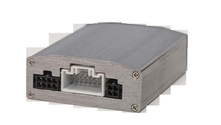
6 Dimensions (mm/in) Control Module 63mm/2.49" 87mm/3.43" 26mm/1.02" 63mm/2.49" LED Indicator 9.5mm/0.37" 18mm/0.7" 166mm/6.54" 6
7 Specifications Operating Voltage 12V DC Current Consumption 200mA Power Consumption 2.4W Operating Temperature Range -40o - +85oC Detection Range 50ft (15m) 7
8 15500 Lightwave Drive, Suite 202, Clearwater, Florida Woolmer Way, Bordon, Hampshire, United Kingdom tel - +44(0) (sales) - +44(0) (technical) EchoMaster is a Power Brand of AAMP Global. EchoMaster.com REV
Rear EU Number Plate Sensor System User Manual SS-NP2
 User Manual Introduction Congratulations on purchasing EchoMaster parking sensors. This ultrasonic detection system is designed to assist in the avoidance of obstacles while reversing. Disclaimer: EchoMaster
Vehicle Rear Observation System With Integrated Parking Sensors
 Vehicle Rear Observation System With Integrated Parking Sensors Model: CAMSBAR Installation/User Manual Features: 2.5" LCD Color Display 2 Ultra Sonic Rear Obstacle Sensors On-screen Display Function Automatically
TE-BSM User Manual. l ::: J TECH SUPPORT. MetraDealer.com
 TE-BSM User Manual ibeamusa.com MetraDealer.com techsupport@metra-autosound.com TECH SUPPORT l ::: J 800-253-8324 Features The TE-BSM Blind Spot Monitor is designed with the latest microwave technology
KIT Parking Sensor 814
 KIT Parking Sensor 814 INSTALLATION AND USE MANUAL UK AC 745/UK Rev. 04-01/14 1 3 x BLACK x BLUE 15 3 5 4 5 BROWN BLACK-BLUE R 13 MAIN UNIT BLACK 4 BLUE 6 6a 7 8 9 10 11 10 x 1 PRIMER 3M 498UV 13 14 15
Model: PSB100. Rear Parking Sensor System. Installation Manual TABLE OF CONTENTS
 Rear Parking Sensor System Model: PSB100 Installation Manual TABLE OF CONTENTS Warnings...2 Product Description...3 Packing List...3 Installation Instructions...4 Mounting the Sensors...4 Installing the
Installation Guide. Blind Spot Detection / ADVBSD20 REV. A
 Guide Blind Spot Detection / ADVBSD20 REV. A Kit Contents System Layout NO. Item QTY. Image 1 BSD Sensor 2 2 GPS Module 1 3 Main Harness 1 BUZZER GPS Module 4 Sensor Harness 2 Left LED Right LED 5 GPS
4 Sensor Backup Obstacle Sensing System Model: ACAB104 Installation Manual
 4 Sensor Backup Obstacle Sensing System Model: ACAB104 Installation Manual 0 5 10 Features: Four reversing sensors detect obstacles between 1-7 feet Includes 0, 5, and 10 angle sensor sleeves to fit most
INSTALLATION INSTRUCTIONS:
 INSTALLATION INSTRUCTIONS: The CA-5030 is an ultrasonic parking assist system designed for use on the rear bumper of most cars and trucks. This system detects any people or objects behind the vehicle using
INSTALLATION INSTRUCTIONS:
 INSTALLATION INSTRUCTIONS: The CA-5010.II is an ultrasonic parking assist system designed for use on the rear bumper of most cars and trucks. This system detects any people or objects behind the vehicle
Hawkeye Plus Reverse Assistance System Installation Instructions
 An ISO 9001:2000 Registered Company Hawkeye Plus Reverse Assistance System Installation Instructions To aid in installation, first gain access to the connection points. Remove any interior panels covering
Owner s Manual BSS1. Microwave Radar Blind Spots System Version1.2
 Owner s Manual BSS1 Microwave Radar Blind Spots System Version1.2 Table of Contents I. Items List... 2 II. Technical Specification... 3 III. Wiring Diagram.... 3 IV. Wire Connection Diagram... 4 V. Installation
HAWK401-A Reverse Assistance System
 An ISO 9001:2008 Registered Company HAWK401-A Reverse Assistance System Introduction The HAWK401-A Reverse Assistance System is an ultrasonic distance monitoring system. When the vehicle is in reverse,
REARSENTRY TM BASE KIT ROSTRA OBSTACLE SENSING SYSTEM CONTENTS
 REARSENTRY TM ROSTRA OBSTACLE SENSING SYSTEM BASE KIT 250-1728 CONTENTS Parts List... 2 Parts Diagrams... 2 Before You Start... 5 Installation... 7 Troubleshooting Guide...11 Form #4713, Rev. B, 01-07-04
INSTALLATION GUIDE 8" FLOATING MULTIMEDIA DISPLAY SYSTEM MODEL NUMBER: UN1880. Copyright 2018 StingerElectronics.com
 INSTALLATION GUIDE 8" FLOATING MULTIMEDIA DISPLAY SYSTEM MODEL NUMBER: UN1880 Copyright 2018 StingerElectronics.com MODEL NUMBER: UN1880 INSTALLATION GUIDE CONTENTS Precautions...2 Parts List...3 Mounting
Bucket Harness. Installation Instructions. for Electric Club Car Precedent
 Bucket Harness for Electric Club Car Precedent Installation Instructions Electric Club Car Precedents manufactured after January 1, 2008 require an additional harness to allow the installation of light
Covers All 430, 440, 441 and CJ Series Advanced Security Systems.
 INSTALL GUIDE Covers All 430, 440, 441 and CJ Series Advanced Security Systems www.ultrastarters.com Technical Support: 866-698-5872 ext 0 support@ultrastarters.com FCC/ID Notice This device complies with
ENSURE THAT THE TEMP PROBE FITS YOUR OUTDRIVE BEFORE BEGINNING INSTALLATION.
 715 Center Street Grayslake IL 60030 P: 847-752-2700 F: 847-752-2415 E: info@livorsi.com Drive temp gauge installation instructions Model Number: DCSDT (color) The Livorsi drive temp gauge kit easily installs
Nero 6600H/6601H. Installation Guide. Commercial Vehicle Productivity and Security. Antenna Configuration
 Commercial Vehicle Productivity and Security The 6600H/6601H is a versatile and economical GPS tracking beacon designed for fleet management needs in all commercial vehicles. The H designation in the model
Please read thoroughly before starting installation and check that kit contents are complete.
 Radar Blind Spot Brackets for 2015-Current Toyota RAV4 (Part # RDBS-1411) ***REQUIRES RDBS-1400 UNIVERSAL RADAR BLIND SPOT SYSTEM*** Please read thoroughly before starting installation and check that kit
Installation Manual for Rear Park Assist
 Installation help? 1. Go to www.echomaster.com 2. Click on the [Login Area] located on the side blue bar. 3. Click [Technician/Installer Training & Support Site] 4. Click [Return User/Click here to Log
U L T I M A T E R A D A R / L A S E R D E F E N S E S Y S T E M
 S m a r t e r Q u i e t e r M o r e A c c u r a t e U L T I M A T E R A D A R / L A S E R D E F E N S E S Y S T E M Installation Manual PASSPORT 9500ci Comes Complete Front Radar Receiver Miniature weatherproof
CLASSIC II Portable Braking System
 39495 CLASSIC II Portable Braking System Inventor and Leader in Portable Technology! INSTRUCTIONS NEED HELP? CALL - 1-800-470-2287 (MONDAY - FRIDAY 8AM - 5PM CST) WARNING Read all instructions before installing
A/C PRESSURE MONITOR INSTALLATION INSTRUCTIONS SYSTEM OPERATION GREEN INDICATOR LIGHT
 A/C PRESSURE MONITOR INSTALLATION INSTRUCTIONS Do not attempt to clean or inspect anything while the engine is running. Cleaning and inspection must be done by a certified mechanic. All A/C service must
AOM-78 7 MONOCHROME OBSERVATION 90 DAY/12 MONTH LIMITED WARRANTY
 BACK COVER FRONT COVER UDIOVOX The Mobile Electronics Company PECIALIZED PPLICATIONS, L.L.C. 90 DAY/12 MONTH LIMITED WARRANTY AUDIOVOX SPECIALIZED APPLICATION, LLC (the company) warrants to the original
Installation Instructions
 Installation Instructions AMP RESEARCH Power Step by Bestop Automatic Retracting Running Board Vehicle Application Nissan Titan King Cab 2004 and newer (5 ft.) Part Number: 75106-01 Nissan Titan Crew Cab
Instruction Manual. Backup Sensor Reversing System RVS-RS103
 Instruction Manual Backup Sensor Reversing System RVS-RS103 RVS Systems, Inc. 2017 TABLE OF CONTENTS System Description............................ 03 Safety Information........................... 04 Before
TOYOTA 4-RUNNER 2006 HANDS FREE PHONE INTERFACE 7/24/06
 7/24/06 Part Number: 00016-00003-02 Accessory Code: BT1 Kit Contents Item # Quantity Reqd. Description 1 1 UIB -USER INTERFACE 2 1 CONTROL MODULE 3 1 USER GUIDE 4 1 HARDWARE BAG 5 1 INSTALLATION INSTRUCTIONS
TOYOTA RAV TRAILER WIRE HARNESS Preparation
 Preparation Part Number: PU322-42013-UW Kit Contents Item # Qty Description 1 1 Trailer Module Harness 2 1 Trailer 4-Flat Harness 3 1 Trailer Power Wire Harness 4 1 Mounting Bracket, 4-Flat 5 2 Screw #10-24
SCION FRS FOG LIGHTS. Part Number: SFR-313
 Part Number: SFR-313 Kit Contents Item # Quantity Reqd. Description 1 2 Light Housings 2 2 Fog Light bezels 3 1 Harness bag 4 1 User s card 5 1 Switch 6 1 Fuse jumper Hardware Bag Contents Item # Quantity
P5000 Series Owners Manual 12/16/04 5:16 PM Page 1. Owners Manual
 P5000 Series Owners Manual 12/16/04 5:16 PM Page 1 Owners Manual P5000 Series Owners Manual 12/16/04 5:16 PM Page 2 C ongratulations, You have made a wise investment and an excellent choice in selecting
Installation Instructions
 Installation Instructions www.bestop.com - We re here to help! Visit our web site and click on Ask a Question INSTALLATION TIME SKILL LEVEL Automatic Retracting Running Board Vehicle Application Chevy
Blind Spot Radar Bar with Two Microwave Sensors and Built-in Camera Version1.0
 Owner s Manual BSS2LPBC Blind Spot Radar Bar with Two Microwave Sensors and Built-in Camera Version1.0 Table of Contents I...Items List...2 II...Technical Specification...3 III...Installation Diagram...3
Wiring Installation Instructions for : Pressure. Wiring Installation Instructions for : Temperature. 2 1/16 Spek Pro Professional Racing Gauge
 Wiring Installation Instructions for : Pressure DIAGRAM 1 Pressure Sensor 1/8 NPT 3 AMP Wiring Installation Instructions for : Temperature GAUGE 12-Pin Wiring Harness & Plug Firewall Grommet DIAGRAM 2
GENUINE PARTS INSTALLATION INSTRUCTIONS
 GENUINE PARTS INSTALLATION INSTRUCTIONS 1. 2. 3. 4. DESCRIPTION: Accent light Kit APPLICATION: Infiniti JX (2013) PART NUMBER: 999F3 YY000 - Universal Accent Lighting Kit. KIT CONTENTS: Item QTY Description
TOYOTA VENZA 2009 TRAILER WIRE HARNESS Procedure
 Part Number: PT791-0T099 Kit Contents Item # Quantity Reqd. Description 1 1 Trailer Wire Harness Module 2 1 4-Flat Harness 3 1 Battery Power Wire Harness 4 1 Mounting Bracket, 4-Flat 5 2 Screw #10-24 6
SUBARU Rear Obstacle Detection System 2004 onward
 SUBARU Rear Obstacle Detection System IMPREZA 5 DOOR 2004 onward ENSURE THE SET-UP PROCEDURE IS CARRIED OUT FOLLOWING INSTALLATION (See Pg 4) IMPREZA 5 DOOR JUNE 04 MODEL ONWARDS KEY POINTS OF THE INSTALLATION
SUBARU Rear Obstacle Detection System 2004 onward
 SUBARU Rear Obstacle Detection System IMPREZA 4 DOOR 2004 onward ENSURE THE SET-UP PROCEDURE IS CARRIED OUT FOLLOWING INSTALLATION (See Pg 4) IMPREZA 4 DOOR JUNE 04 MODEL ONWARDS KEY POINTS OF THE INSTALLATION
TOYOTA RAV HANDS FREE PHONE INTERFACE 9/06/06
 9/06/06 Part Number: 00016-32103-01;00003-04 Accessory Code: BT1 Kit Contents Item # Quantity Reqd. Description 1 1 UIB -USER INTERFACE 2 1 CONTROL MODULE 3 1 USER GUIDE 4 1 HARDWARE BAG 5 1 INSTALLATION
Marine Products. SL-3 Engine Controls. Owner s Manual
 Marine Products SL-3 Engine Controls Owner s Manual This manual must be accessible to the owner/user of this Morse marine product. Includes installation, operation and maintenance instructions for your
TOYOTA FJ CRUISER 2007 HANDS FREE PHONE INTERFACE 7/10/06
 7/10/06 Part Number: 00016-00003-02 Accessory Code: BT1 Kit Contents Item # Quantity Reqd. Description 1 1 UIB -USER INTERFACE 2 1 CONTROL MODULE 3 1 USER GUIDE 4 1 HARDWARE BAG 5 1 INSTALLATION INSTRUCTIONS
Please read all of the installation instructions carefully before installing the product. Improper installation will void manufacturer s warranty.
 TM 1 What s in the Box? Note: Configuration will vary depending what item options you select. ire 1 Color Sony CCD night vision weather proof backup camera 1 16 Camera Cable 1 Power Connection Wire Table
GENUINE PARTS INSTALLATION INSTRUCTIONS
 GENUINE PARTS INSTALLATION INSTRUCTIONS 1. 2. 3. 4. DESCRIPTION: Security Light Kit APPLICATION: Altima Coupe and Sedan (2011+) PART NUMBER: 999F4 AX008 - Universal Security Lighting Kit. KIT CONTENTS:
TOYOTA VENZA 2009 TRAILER WIRE HARNESS Procedure
 Part Number: PT791-0T099 Kit Contents Item # Quantity Reqd. Description 1 1 Trailer Wire Harness Module 2 1 4-Flat Harness 3 1 Battery Power Wire Harness 4 1 Mounting Bracket, 4-Flat 5 2 Screw #10-24 6
Roll Up Door Operator
 INSTRUCTIONS & OWNERS MANUAL Roll Up Door Operator 2 INDEX Preparation before installation 4. Terms and definitions 5. Pictures & names of parts 6. Mounting the weight bar 7. Installing the operator 7.
PLEASE READ THIS INSTRUCTIONS CAREFULLY, BEFORE YOU START INSTALLATION
 INSTALLATION INSTRUCTIONS PART NUMBER: L0SXC000 DESCRIPTION: 09 ASCENT TRAILER HITCH PLEASE READ THIS INSTRUCTIONS CAREFULLY, BEFORE YOU START INSTALLATION SAFETY PRECAUTION: When installing Trailer Hitch,
Installation Instructions PowerBoard Automatic Retracting Running Board
 Installation Instructions PowerBoard Automatic Retracting Running Board Vehicle Application Chevy Silverado/GMC Sierra Extended Cab 2007 and newer (excluding 2011 Diesels) Part Number: 75123-15 Chevy Silverado/GMC
WARNING WARNING WARNING. English Quick start guide CAUTION CAUTION. Installation Precautions
 English Quick start guide Symbol Identification This manual uses symbols and icons to indicate safety precautions and concerns during the installation procedure. Be sure to carefully read and understand
Installation and Service Manual M² Sync Room Slideout System without Room Lock Connectors on Control Box
 Installation & Service Manual M² Sync Room Slideout System w/o Room Locks: for Slideout Control Box# 1510000143 and 1510000198 Figure 1 01/13 Power Gear #3010002088 Rev. 0C Installation and Service Manual
INSTALLATION MANUAL AP60B INSTALLATION MANUAL
 INSTALLATION MANUAL 2. TOOLS REQUIRED The following is a list of tools required to properly install the cruise control. While this unit may be installed without some of the tools listed, it is recommended
Installation Instructions PowerBoard Automatic Retracting Running Board
 Installation Instructions PowerBoard Automatic Retracting Running Board Vehicle Application Chevy Silverado/GMC Sierra Extended Cab 2007 and newer (excluding 2011 Diesels) Part Number: 75123-15 Chevy Silverado/GMC
Installation Instructions LamboStyleDoors (The instruction are to be used as a reference. Please repeat for both doors)
") Installation Instructions LamboStyleDoors (The instruction are to be used as a reference. Please repeat for both doors) Mercedes C-Class Sport coupé type W203 Part number 500 25 009 Pre installation check
Installation Instructions LamboStyleDoors (The instruction are to be used as a reference. Please repeat for both doors) Mercedes C-Class Sport coupé type W203 Part number 500 25 009 Pre installation check
Installation Instructions PowerBoard Automatic Retracting Running Board
 Installation Instructions PowerBoard Automatic Retracting Running Board Vehicle Application Chevy Silverado/GMC Sierra Crew Cab 1999 2007 (7 ft.) : 75113-15 www.bestop.com - We re here to help! Visit our
Installation & Service Manual
 Installation & Service Manual for M² Sync Slideout Control Box #1510000122 CONTENTS Introduction Installation Installation Problems Program Mode Operation Mode Preventative Maintenance Fault Diagnostics
NOTE. Installation and Service Manual Dual Planetary Gearmotor Slim Rack Slide Out System
 Installation & Service Manual Slim Rack In-Wall Slide Out System Control Box Part Number 1510000199 Content Copyright LCI/Power Gear Issued: December 2014 #3010002588, Rev. 0E Installation and Service
PLEASE READ THESE INSTRUCTIONS CAREFULLY, BEFORE YOU START INSTALLATION
 PART NUMBER: L0SSJ000 INSTALLATION INSTRUCTIONS DESCRIPTION: FORESTER TRAILER HITCH PLEASE READ THESE INSTRUCTIONS CAREFULLY, BEFORE YOU START INSTALLATION SAFETY PRECAUTION: When installing Trailer Hitch,
Remove the 3-11mm nuts holding mirror on. Don t drop the nuts!
 2005-2012 Ford Mustang Puddle Lamp Kit Parts List: Quantity: Tool List: LED Lamps 2 Flat head screwdriver Seals 2 Ratchet & Socket set OR Nuts 2 Adjustable Wrench Wiring harness 1 Drill & 11/16 th bit
Installation Instructions
 Equipment Required: Installation Instructions Fastener Kit: F Wrenches: 8mm, 13mm, 3/4, 15/16 Drill Bits: 1/4 Other Tools: Drill, Reciprocating Saw, File WARNING: Under no circumstances do we recommend
Installation Instructions
 Installation Instructions Automatic Retracting Running Board Vehicle Application Ford F150 Supercrew 2001-2003 (2004 Heritage) Part Number: 75111-01 www.bestop.com - We re here to help! Visit our web site
Installation Instructions
 Equipment Required: Fastener Kit: F Wrenches: 3/4, 15/16 Drill Bits: 1/4 Other Tools: Drill Short & Long Bed All Megacabs 9464/9474 HIDE-A-GOOSE HITCH INSTALLATION WARNING: Under no circumstances do we
Select II Portable Braking System
 39523 Select II Portable Braking System Inventor and Leader in Portable Technology! INSTRUCTIONS NEED HELP? CALL - 1-800-470-2287 (MONDAY - FRIDAY 8AM - 5PM CST) WARNING Read all instructions before installing
Sprayer Control. Manual for SprayLink Cable Installations. Tank. Jet Agitator. Agitator Valve. Diaphragm Pump. Pressure Transducer.
 Sprayer Control Plumbing & Installation Manual for SprayLink Cable Installations Tank Jet Tank Shut-Off Diaphragm Pump Electric Ball s Transducer Strainer Relief Regulating Copyrights 2012 TeeJet Technologies.
Guardian Personal Mobility Lift Interlock GRD701-AR ( Dodge Sprinter) Installation Instructions
 Installation Instructions") An ISO 9001:2000 Registered Company Guardian Personal Mobility Lift Interlock GRD701-AR (2007-2008 Dodge Sprinter) Installation Instructions GUARDIAN MODULE Remove drivers seat and step-well trim for access.
An ISO 9001:2000 Registered Company Guardian Personal Mobility Lift Interlock GRD701-AR (2007-2008 Dodge Sprinter) Installation Instructions GUARDIAN MODULE Remove drivers seat and step-well trim for access.
AMP RESEARCH TECH SUPPORT (Press 2) Monday - Friday, 6:00 AM - 5:00 PM PST
 Monday - Friday, 6:00 AM - 5:00 PM PST") INSTALLATION GUIDE APPLICATION AMP Part # Ram 1500 Crew Cab 2019 76240-01A Ram 1500 Quad Cab 2019 76240-01A INSTALLATION TIME 3-5 Hours Professional installation recommended SKILL LEVEL 1 2 3 4 4= Experienced
INSTALLATION GUIDE APPLICATION AMP Part # Ram 1500 Crew Cab 2019 76240-01A Ram 1500 Quad Cab 2019 76240-01A INSTALLATION TIME 3-5 Hours Professional installation recommended SKILL LEVEL 1 2 3 4 4= Experienced
3-5 Hours Professional installation recommended
 I N S T A L L A T I O N G U I D E APPLICATION AMP Part # Chevrolet Silverado 2500/3500 / GMC Sierra 2500/3500 - Ext. Cab * 2007-201 75126-01A Chevrolet Silverado 2500/3500 / GMC Sierra 2500/3500 - Crew
GENUINE PARTS INSTALLATION INSTRUCTIONS
 GENUINE PARTS INSTALLATION INSTRUCTIONS 1. 2. 3. 4. DESCRIPTION: Accent light Kit APPLICATION: R42H (2011) PART NUMBER: 999F3 AW000 - Universal Accent Lighting Kit. KIT CONTENTS: Item QTY Description Service
Adjustable Light Kits E-Z-Go TXT All Models Installation Instructions
 Adjustable Light Kits E-Z-Go TXT All Models 1996-2013 Installation Instructions Caution: Please read through the instructions carefully. Before starting this project, remove the system s positive and negative
END USER TERMS OF USE
 END USER TERMS OF USE The following is the End Users Terms of Use as it currently appears in the Mobileye User Manual and Warranty information. This is here for your review and information; it is subject
AUTO-BLiP. User Manual Porsche INTELLIGENT DOWNSHIFTS. Version 1.2
 AUTO-BLiP INTELLIGENT DOWNSHIFTS www.auto-blip.com User Manual 2005+ Porsche Version 1.2 Copyright 2012 Tractive Technology, LLC. All rights reserved. Page 1 WARNING Use of the AUTO-BLiP while driving
Installation Manual. AutoSteer. Gleaner Combine. AutoGuide 2 Steer Ready. Supported Models A66 A76 R66 R76 S67 S77 PN: A
 Installation Manual AutoSteer Gleaner Combine AutoGuide 2 Steer Ready Supported Models A66 A76 R66 R76 S67 S77 PN: 602-0312-01-A LEGAL DISCLAIMER Note: Read and follow ALL Instructions in this manual carefully
GPS AutoSteer System Installation Manual
 GPS AutoSteer System Installation Manual Supported Vehicles Case IH Vehicles Case 2577 Combines Case 2588 Combines Accuguide Ready PN: 602-0233-01-A LEGAL DISCLAIMER Note: Read and follow ALL instructions
INSTALLATION INSTRUCTIONS
 INSTALLATION INSTRUCTIONS Models: 7105 & 7105TK Dodge Ram 1500 ('02 Current) Ram 2500 & 3500 '03 - Current with stock manual mirrors. IF YOU DO NOT CURRENTLY HAVE MANUAL MIRRORS, THE WRONG SET HAS BEEN
Gentex by VOXX Corporation Installation Instructions
 KIT CONTENTS: Item Qty Part Number Description 1 1: ADVGEN20A 7 Pin Auto-Dimming Mirror with Compass and Temperature 2 1 Gentex by VOXX Corporation Installation Instructions Contact VOXX Customer Service
MICROWAVE RADAR BLIND SPOT DETECTION SYSTEM. User's Manual. BSD Type:2016. Version:V2.0. AutoEase Technology
 MICROWAVE RADAR BLIND SPOT DETECTION SYSTEM User's Manual BSD Type:2016 Version:V2.0 AutoEase Technology Catalog I. Components... 1 II. System Specification... 2 III. Install Caution... 3 IV. Requirements
Fitting Instructions: Tiger 800 and Tiger 800XC A and A to VIN and from VIN to VIN A
 English Fitting Instructions: Tiger 800 and Tiger 800XC A98800 and A9880 to VIN 64 and from VIN 69457 to VIN 607 A98807 Thank you for choosing this Triumph genuine accessory kit. This accessory kit is
Sight Addvantage by Rostra License Plate Backup Camera
 80.00 mm Customer Name Installing Dealer Date Purchased Date Installed VIN# Vehicle Mileage 2016 Rostra Precision Controls 2519 Dana Dr. Laurinburg, NC 28352 300-81LPB-M Sight Addvantage by Rostra License
Installation instructions, accessories. Parking assistance, rear
 Installation instructions, accessories Instruction No 31330676 Version 1.4 Part. No. 30758088, 9487266, 30786087, 31359215 Parking assistance, rear Volvo Car Corporation Parking assistance, rear- 31330676
DIGIGAUGE P R E S S U R E D I S P L A Y S Y S T E M I N S T R U C T I O N M A N U A L
 DIGIGAUGE P R E S S U R E D I S P L A Y S Y S T E M I N S T R U C T I O N M A N U A L Thank you for purchasing DigiGauge by ZAETECH Disclaimer DigiGauge is for show and off road use only. By using this
TOYOTA PRIUS C FOG LIGHT (Halogen & LED)
") TOYOTA PRIUS C 2012-14 FOG LIGHT (Halogen & LED) Part Number: TPC-312 / TPC-812 Kit Contents Item # Quantity Reqd. Description 1 2 Fog Lamps 2 2 Bezels 3 1 Switch Assembly 4 1 Fog Light Operation guide
TOYOTA PRIUS C 2012-14 FOG LIGHT (Halogen & LED) Part Number: TPC-312 / TPC-812 Kit Contents Item # Quantity Reqd. Description 1 2 Fog Lamps 2 2 Bezels 3 1 Switch Assembly 4 1 Fog Light Operation guide
Ford Super Duty SuperCab A Ford Super Duty SuperCrew A
 I N S T A L L A T I O N G U I D E APPLICATION LENGTH MODEL YR PART # Ford Super Duty SuperCab 72 2017 76235-01A Ford Super Duty SuperCrew 85 2017 76235-01A INSTALLATION TIME 2-3 Hours Professional installation
Plus SABRE LIGHTBARS
 INSTALLATION AND INSTRUCTION MANUAL Plus SABRE LIGHTBARS Models 5364LED, 5462LED, 5464LED and 5564LED PLIT445 REV. D 2/2/18 Keep any radio frequency sensitive equipment at least 20 from the bar and power
Installation and Service Manual M² Sync Room Slideout System without Room Lock Connectors on Control Box
 Installation & Service Manual M² Sync Room Slideout System w/o Room Locks: for Slideout Control Box# 1510000143 and 1510000198 Figure 1 01/13 Power Gear #3010002088 Rev. 0C Installation and Service Manual
IVTM Installation Manual
 Integrated Vehicle Tire Pressure Monitoring IVTM Installation Manual 2nd edition Copyright WABCO 2006 Vehicle Control Systems An American Standard Company The right of amendment is reserved Version 002/06.06(us)
INSTALLATION GUIDE. AMP RESEARCH TECH SUPPORT (Press 2) Monday - Friday, 6:00 AM - 5:00 PM PST
 Monday - Friday, 6:00 AM - 5:00 PM PST") INSTALLATION GUIDE APPLICATION MODEL YR PART # HUMMER H2 2003-2009 75107-01A INSTALLATION TIME 3-5 hrs SKILL LEVEL 1 2 3 = Experienced TOOLS REQUIRED Safety goggles Measuring tape Flat blade screwdriver
INSTALLATION GUIDE APPLICATION MODEL YR PART # HUMMER H2 2003-2009 75107-01A INSTALLATION TIME 3-5 hrs SKILL LEVEL 1 2 3 = Experienced TOOLS REQUIRED Safety goggles Measuring tape Flat blade screwdriver
Installation Instructions
 Equipment Required: Fastener Kit: F Wrenches: 15/16, 10 mm Drill Bits: 1/4 Other Tools: Drill, Reciprocating Saw 9464/9474 HIDE-A-GOOSE HITCH INSTALLATION All Fasteners Typical, Both Sides WARNING: Under
jegs.com
 Contents Wiring Harness w/ Fuse Panel Installation Instructions Turn Signal Plug w/ Terminals 2 Headlight Plugs 3/4 Grommet 10 ¼ Terminals 4 Ring Terminals 10 Wire Ties Fusible Link 2 Screws & Nuts 2 Plastic
TOYOTA im INTERIOR LIGHT KIT Preparation
 Preparation Part Number: PT922-12170 Kit Contents Item # Quantity Reqd. Description 1 1 Main Wire Harness 2 1 Switch 3 1 Switch Header 4 1 ECU 5 1 ECU Bracket 6 1 Hardware Kit 7 1 Instruction Card 8 1
11 ½" MODEL SINGLE CHAIN CONVEYOR
 11 ½" MODEL SINGLE CHAIN CONVEYOR USER S MANUAL 11 ½" Chain conveyor Revision 2011-05-31 2 CONTENTS WARRANTY...3 FOREWORD...4 SAFETY PRECAUTIONS...5 ASSEMBLY INSTRUCTIONS...6 SPECIFICATIONS...6 ASSEMBLING
GPS AutoSteer System Installation Manual
 GPS AutoSteer System Installation Manual John Deere Track Supported Models 8295RT 8320RT 8345RT PN: 602-0255-01-A LEGAL DISCLAIMER Note: Read and follow ALL instructions in this manual carefully before
Part Number: TTU-BGB14-DRL TTU-BGP14-DRL
 11/15/16 TOYOTA TUNDRA 2014-17 Billet Grille w/led DRL Part Number: TTU-BGB14-DRL TTU-BGP14-DRL Kit Contents Item # Quantity Reqd. Description 1 2 LED DRL 2 1 Driver Box 3 1 Switch 4 1 User Card 5 2 Hardware
Detroit Speed, Inc. Electric Headlight Door Kit Corvette P/N: &
 Detroit Speed, Inc. Electric Headlight Door Kit 1968-82 Corvette P/N: 122006 & 122007 The Detroit Speed Inc. Electric Headlight Door Kit replaces the stock vacuum actuated system on all 1968-82 Corvettes.
Love. It s what makes a Subaru, a Subaru. Quick Guide IMPREZA
 Love. It s what makes a Subaru, a Subaru. Quick Guide IMPREZA 2017 Table of Contents EyeSight 2 EyeSight and EyeSight Functions 3 EyeSight Operation 4 Steering Wheel Controls 5 Lane Departure Warning and
Draper Platform Adaptation Bundle
 Draper Platform Adaptation Bundle 7050-Series Self-Propelled Forage Harvester 900D-Series Draper Platform RC042050 Operator s Manual Includes installation, operating, adjustment, technical, repair parts
North American Signal Co. Be Seen, Be Safe. CLKE6H90(S) System with Hi/Lo option Installation Guide
 System with Hi/Lo option Installation Guide") North American Signal Co. www.nasig.com Be Seen, Be Safe. CLKE6H90(S) System with Hi/Lo option Installation Guide Safety First This installation guide is intended to provide all the necessary information
North American Signal Co. www.nasig.com Be Seen, Be Safe. CLKE6H90(S) System with Hi/Lo option Installation Guide Safety First This installation guide is intended to provide all the necessary information
INSTALLATION INSTRUCTIONS
 INSTALLATION INSTRUCTIONS Accessory Application CR-V Publications No. AII 32953-34081 Issue Date NOV 2006 PARTS LIST 2 Corner sensor clips Backup Sensor Attachment Kit P/N 08V67-SWA-100A Back-up sensor
POWER GEAR SLIDE-OUT MANUAL
 POWER GEAR SLIDE-OUT MANUAL Operation Guide FLUSH FLOOR SLIDE-OUT SYSTEM FOR AMERICAN COACH PRODUCTS 82-S0220-01 Rev. 1 AMERICAN COACH SLIDE-OUT MANUAL FLUSH FLOOR SYSTEM TABLE OF CONTENTS SECTION PAGE
Installation Instructions
 Equipment Required: Fastener Kit: F Wrenches: 3/4, 15/16 Drill Bits: 1/4 Other Tools: Drill WARNING: Under no circumstances do we recommend exceeding the towing vehicle manufacturers recommended vehicle
MICROWAVE RADAR BLIND SPOT DETECTION SYSTEM
 MICROWAVE RADAR BLIND SPOT DETECTION SYSTEM User s Manual VTBSD1 Version:V1.0 Catalog I. Components... 1 II. System Specification... 2 III. Install Caution... 3 IV. Requirements for Radar Sensor Setting...
Installation Instructions PowerBoard Automatic Retracting Running Board
 Installation Instructions PowerBoard Automatic Retracting Running Board Vehicle Application Chevy Silverado/GMC Sierra Extended Cab Diesel 2011 and newer Part Number: 75147-15 Chevy Silverado/GMC Sierra
3-5 Hours Professional installation recommended
 INSTALLATION GUIDE APPLICATION LENGTH MODEL YR PART # Nissan Titan / Titan XD - Crew Cab 72 2016-2018 76120-01A Nissan Titan / Titan XD - King Cab 62 2017-2018 76120-01A Nissan Titan / Titan XD - Single
GENUINE PARTS INSTALLATION INSTRUCTIONS
 GENUINE PARTS INSTALLATION INSTRUCTIONS 1. 2. 3. 4. DESCRIPTION: Illuminated Kick Plate Kit APPLICATION: Murano PART NUMBER: 999G6 C2000, 999G6 C2100, 999G6 C2200 999Q9 AY001 - Accessory Service Connector