BOXER KING 5600/5600R TRUCK TYRE CHANGER
|
|
|
- Ralf Gordon
- 6 years ago
- Views:
Transcription
1 Author Stefano Muzzioli BOXER KING 5600/5600R TRUCK TYRE CHANGER SERVICE MANUAL 1
2 UPDATING GUIDE: Release B of 02/04/2010 Removed 50 or 60 Hz At page 49 2
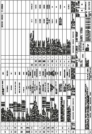
3 TABLE OF CONTENTS 1.0 Introduction Pag Tools and special tools required Pag Use of digital multimeter Pag Diagrams section: electric and hydraulics Pag Electric diagram for CE proved King 5600 Pag Electric diagram for King 5600 supplied at 200/3/60 Pag Electric diagram for CE approved King 5600R Pag Electric diagram for King 5600R supplied at 200/3/60 Pag Hydraulic diagram for CE approved King 5600 Pag Hydraulic diagram for non CE approved King 5600 Pag Hydraulic diagram for CE approved King 5600R Pag Hydraulic diagram for non CE approved King 5600 R Pag Electric function Pag Access to electric parts Pag Power supply cable and plug: check and replacement Pag Main switch Q1: check and replacement Pag Circuit Breaker Q2: check and replacement Pag Hydraulic motor cable: check and replacement Pag Hydraulic motor: check and replacement Pag Fuses F1,F2,F3: check and replacement Pag Inverter pole switch Q3: check and replacement Pag Chuck motor cables: check and replacement Pag Chuck motor: check and replacement Pag Transformer: check and replacement Pag Fuses F4,F5,F6,F7: check and replacement Pag Link converter: check and replacement Pag Three polar meters K1,K2: check and replacement Pag Portable control cable: check and replacement Pag Switches S1: check and replacement Pag Micro switches S2, S3, and S6: check and replacement Pag Micro switches S2, S3 and S6 holders: check and replacement Pag Shut off cable: check and replacement Pag Shut off switch S4: check and replacement Pag Emergency switch S5: check and replacement Pag Robotic safety switch cable: check and replacement Pag Robotic safety switch: check and replacement Pag Coil connector cable: check and replacement Pag Hydraulic function Pag Access to hydraulic parts Pag Hydraulic oil level: check and levelling Pag High hydraulic pressure circuit: check and adjustment Pag Low hydraulic pressure circuit: check and adjustment Pag Hydraulic pressure of chuck cylinder: check and adjustment Pag Saddle cylinder sliding hydraulic pressure: check and adjustment Pag Hydraulic pump: check and replacement Pag Coil valve: check and replacement Pag King 5600 saddle cylinder: check and replacement Pag King 5600R saddle cylinder: check and replacement Pag King 5600 saddle cylinder seals: check and replacement Pag King 5600R saddle cylinder seals: check and replacement Pag Chuck arm cylinder: check and replacement Pag Chuck arm lowering speed: check and adjustment Pag Chuck arm cylinder seals: check and replacement Pag Chuck cylinder: check and repairing Pag. 96 3
4 6.17 Tool holder cylinder: check and replacement Pag Tool holder cylinder seals: check and replacement Pag King 5600R robotic cylinder: check and replacement Pag King 5600R robotic cylinder seals: check and replacement Pag Mechanical section Pag Saddle: check and adjustment Pag King 5600R saddle slides: check and replacement Pag King 5600 saddle slides: check and replacement Pag King 5600 saddle bushings: check and replacement Pag King 5600R robotic rotation: check and adjustment Pag King 5600R robotic rotor: check and replacement Pag King 5600R lower robotic cam and spring: check and replacement Pag King 5600R tool holder moving cabinet: check and replacement Pag Shutdown pin: check and replacement Pag King 5600R tool holder arm bushings: check and replacement Pag King 5600R hook:check and adjustment Pag King 5600R hook:check and replacement Pag King 5600 hook:check and adjustment Pag King 5600 hook:check and replacement Pag Screw support tool: check and adjustment Pag King 5600 tool holder arm: check and replacement Pag King 5600R tool holder arm: check and replacement Pag Mount - Dismount tool: check and replacement Pag Jaws and claws: check and replacement Pag Worm screw: check and replacement Pag Worm screw seal: check and replacement Pag Chuck seal: check and replacement Pag Trouble shooting Pag Service Bulletins Pag
 AND YEAR (#2),")


5 1.0 INTRODUCTION This technical manual describes maintenance, check and repair operations of the G.S. range of Boxer King 5600 and 5600R and is for use of qualified personnel only. This manual is also applicable to the following models: STARTING FROM JANUARY , THE SERIAL NUMBER HAS CHANGED SEQUENCE OF FIGURES STANDING FOR THE MANUFACTURING MONTH (#1) AND YEAR (#2), REFERENCE NUMBER OF THE MACHINE (#3) AND PROGRESSIVE NUMBER OF THE MACHINE (#5) MANUFACTURED WITH THIS PART NUMBER. THE #4 STILL SHOWS THE MODEL. BOXER KING 5600/5600R ACCU 4560/4560MR HOFMANN JAPAN GX56 HOFMANN MONTY 4400/4400R TIP TOP PROMONT 956 SUPER EIWA WING 311 COATS 9500/9500R Reproduction, translation and accommodation rights are reserved. ALL SAFETY REGULATIONS MUST BE STRICTLY FOLLOWED DURING ANY MAINTENANCE, CHECK AND REPAIR OPERATION. 2.0 TOOLS Before starting any repair operation, make sure that all required tools are available: 1 Set of end wrenches from 8 to 30mm PERSONNEL PERFORMING MAINTENANCE, CHECK AND REPAIR OPERATIONS MUST HAVE BEEN DULY TRAINED BY G.S. AUTHORIZED INSTRUCTORS. Keep this manual constantly updated, by adding Service Bulletins related to Boxer King IMPORTANT! THE IDENTIFICATION DATAS OF EACH MACHINE ARE PRINTED ON A PLATE. UNTILL DECEMBER , THE SERIAL NUMBER IS A SEQUENCE OF FIGURES STANDING FOR THE MANUFACTURING MONTH (#1) AND YEAR (#2), FOLLOWED BY A PROGRESSIVE NUMBER (#3) AND #4 SHOWS THE MODEL. Fig.1 1 Set of screwdrivers (standard and cross type). Fig.2 5


6 1 Set of tube type wrenches from 7 to 13mm. Standard pliers, Seeger pliers and scissor. Fig.3 1 Set of Allen wrenches from 3 to 12mm. Fig.7 Rubber and steel hammers. Fig.4 1 Set of socket wrenches of mm and Allen socket wrench of 10 and 12mm Fig.8 Extractor Fig.5 Dyanamometric wrench. Fig.9 Fig.6 6


7 1 Tool for removal of cylinder pin # Fig.13 1 Manometer with adapter # Fig.10 1 Multimeter, Loctite green type, Silicon Fig.14 2 Calliper wrenches of 5 and 6mm to open the cylinders. Fig.11 1 Ammeter pliers Fig.15 Spanner wrench Fig.12 In addition to a standard set of hand tools, the following special tools are required: 1 Wrench adjustment of saddle clearance #
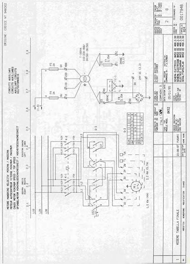
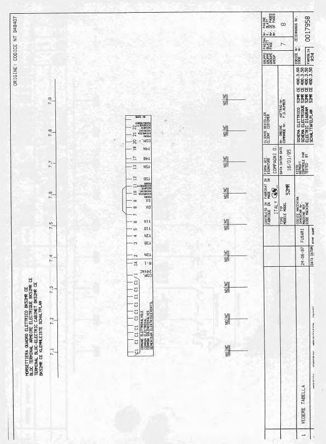
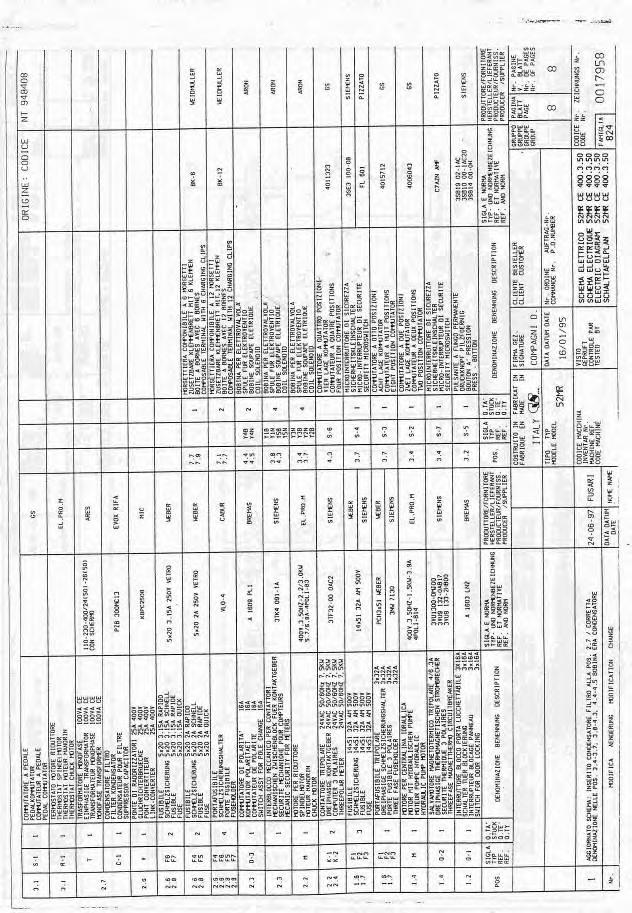
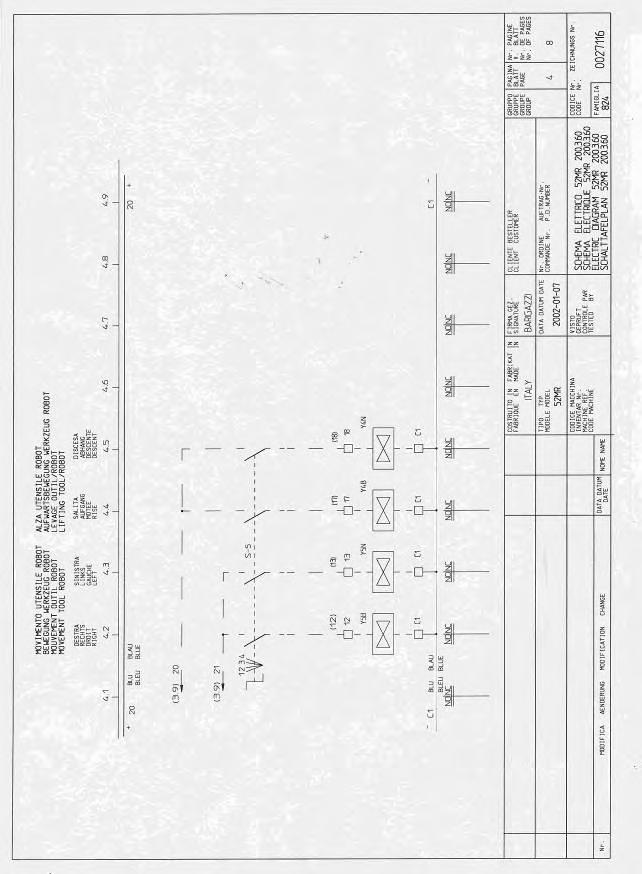
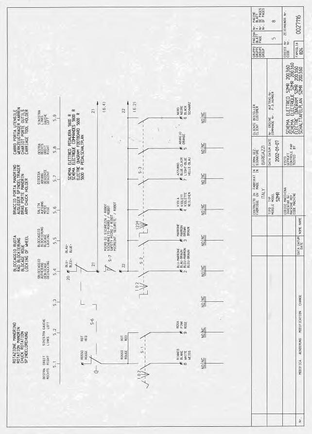
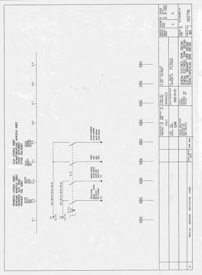
8 2.1 USE OF DIGITAL MULTIMETER In this manual it is frequently required the use of a digital multimeter. We recommend a digital multimeter instead of an analog model because easier to use and more accurate. CAREFULLY READ THE INSTRUCTION MANUAL OF YOUR MULTIMETER FOR EVERY INFORMATION CONCERNING ITS FUNCTIONS. The following short notes are just to remind some important general principles. ALL SAFETY CAUTIONS MUST BE RESPECTED FOR A CORRECT USE OF MEASUREMENT DEVICES. NEVER APPLY TO YOUR MULTIMETER CURRENT OR VOLTAGE HIGHER THAN MULTIMETER MEASUREMENT CAPACITY. PAY EXTRA CARE WHEN MEASURING VOLTAGE BEYOND 50 VOLTS. WHENEVER POSSIBLE DISCONNECT POWER SUPPLY CIRCUIT BEFORE CONNECTING MULTIMETER TERMINALS TO THE CONTACTS. Disconnect power supply. To measure the current intensity, the multimeter must be connected in series with the circuit. Suitably adjust the end of scale selector and Amp selector. If you don't know the probable value of the voltage to measure, start with the highest end-of-scale value. If is displaied and the terminals are connected as per instructions, the polarity (DC) is reversed. To measure resistance (Ohm) values: Disconnect the component to be tested from the rest of the circuit. Suitably adjust the end of scale selector and Ω selector. If you don't know the probable value of the voltage to measure, start with the highest end-of-scale value. 3.0 DIAGRAM SECTION: ELECTRIC AND HYDRAULIC The differences between the King 5600 diagrams and the 5600R ones consist in the robotic tool movement only. The electric diagram includes two more switches while the hydraulic one includes one more coil valve and one more cylinder. To measure VDC values (direct current): Suitably adjust the end of scale selector and VDC selector. If you don't know the probable value of the voltage to measure, start with the highest end-of-scale value. Connect the terminals as per instructions. If is displaied and the terminals are connected as per instructions, the polarity is reversed. To measure VAC values (alternate current): Suitably adjust the end of scale selector and VAC selector. If you don't know the probable value of the voltage to measure, start with the highest end-of-scale value. Connect the terminals as per instructions. To measure current magnitude (AC-DC): 8

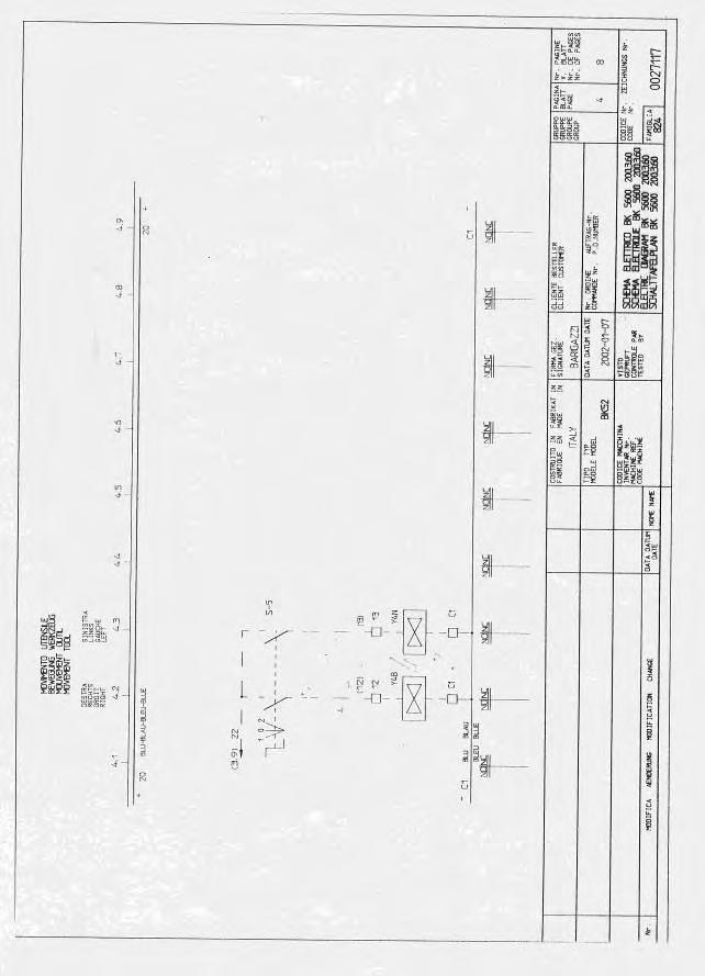
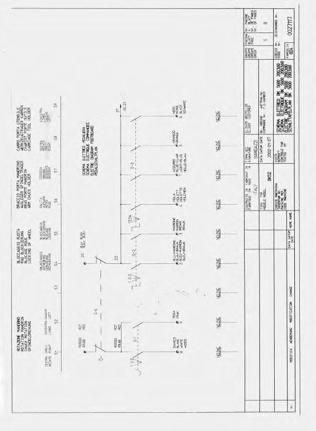
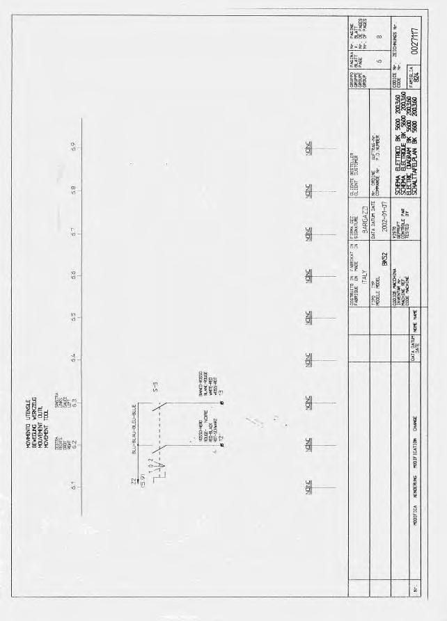
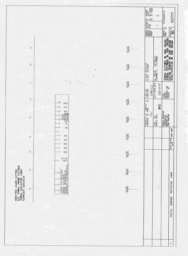
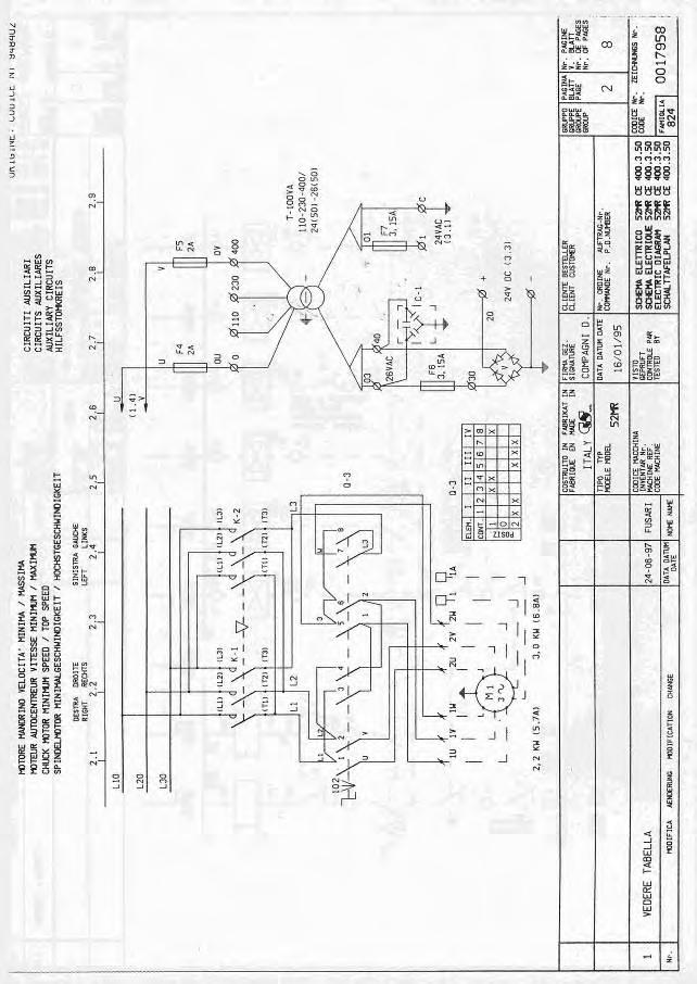
9 3.1 ELECTRIC DIAGRAM FOR CE PROVED KING 5600 Fig.16 9
10 Fig.17 10
11 Fig.18 11
12 Fig.19 12
13 Fig.20 13
14 Fig.21 14
15 Fig.22 15
16 Fig.23 16

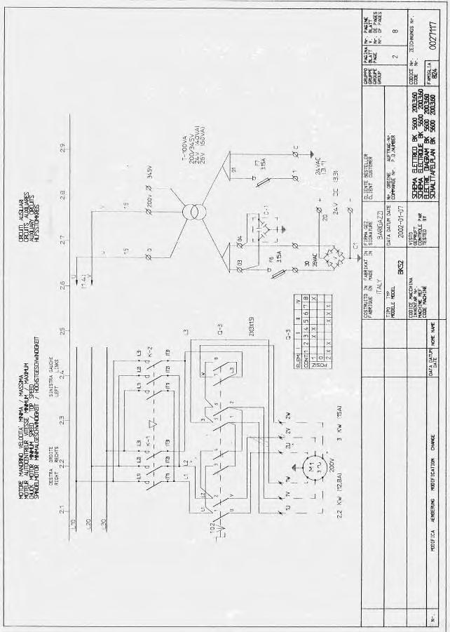
17 3.2 ELECTRIC DIAGRAM FOR KING SUPPLIED AT 200V-3PH-60Hz Fig.24 17
18 Fig.25 18
19 Fig.26 19
20 Fig.27 20
21 Fig.28 21
22 Fig.29 22
23 Fig.30 23

24 Fig.31 24

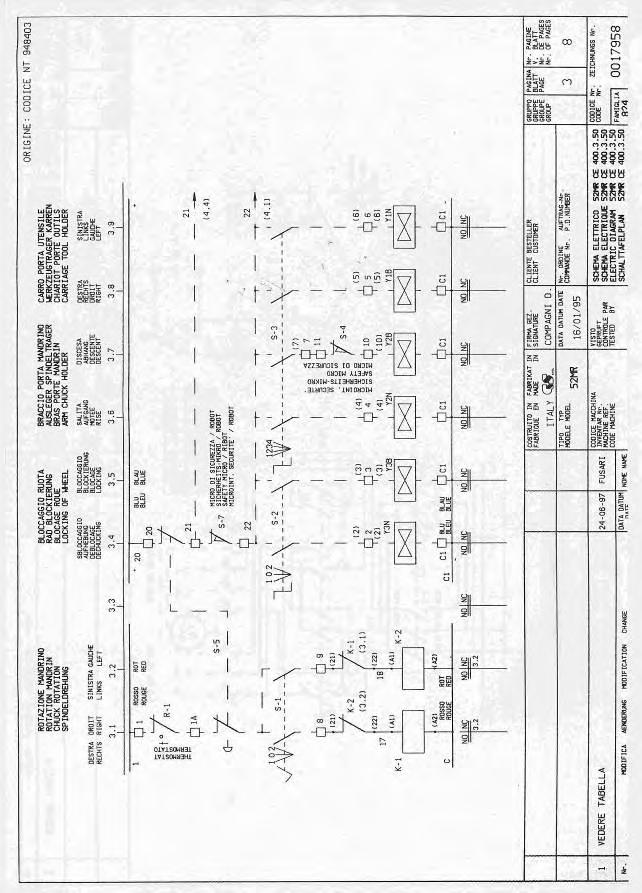
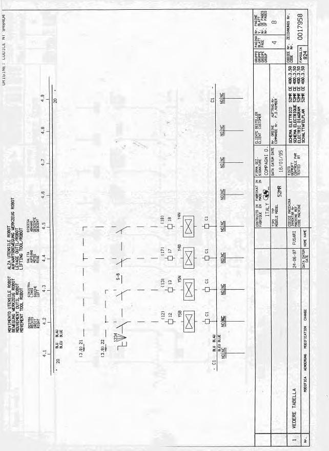
25 3.3 ELECTRIC DIAGRAM FOR CE APPROVED KING 5600R Fig.32 25
26 Fig.33 26
27 Fig.34 27
28 Fig.35 28
29 Fig.36 29
30 Fig.37 30
31 Fig.38 31
32 Fig.39 32

33 3.4 ELECTRIC DIAGRAM FOR KING 5600R SUPPLIED AT 200V 3PH - 60HZ Fig.40 33
34 Fig.41 34
35 Fig.42 35
36 Fig.43 36
37 Fig.44 37
38 Fig.45 38
39 Fig.46 39
40 Fig.47 40

41 3.5 HYDRAULIC DIAGRAM FOR CE APPROVED KING 5600 Fig
42 Fig.49 42

43 3.6 HYDRAULIC DIAGRAM FOR KING 5600 Fig.50 43
44 Fig.51 44

45 3.7 HYDRAULIC DIAGRAM FOR CE APPROVED KING 5600R Fig.52 45
46 Fig.53 46

47 3.8 HYDRAULIC DIAGRAM FOR MACHINE NON CE KING 5600R Fig.54 47
48 Fig.55 48
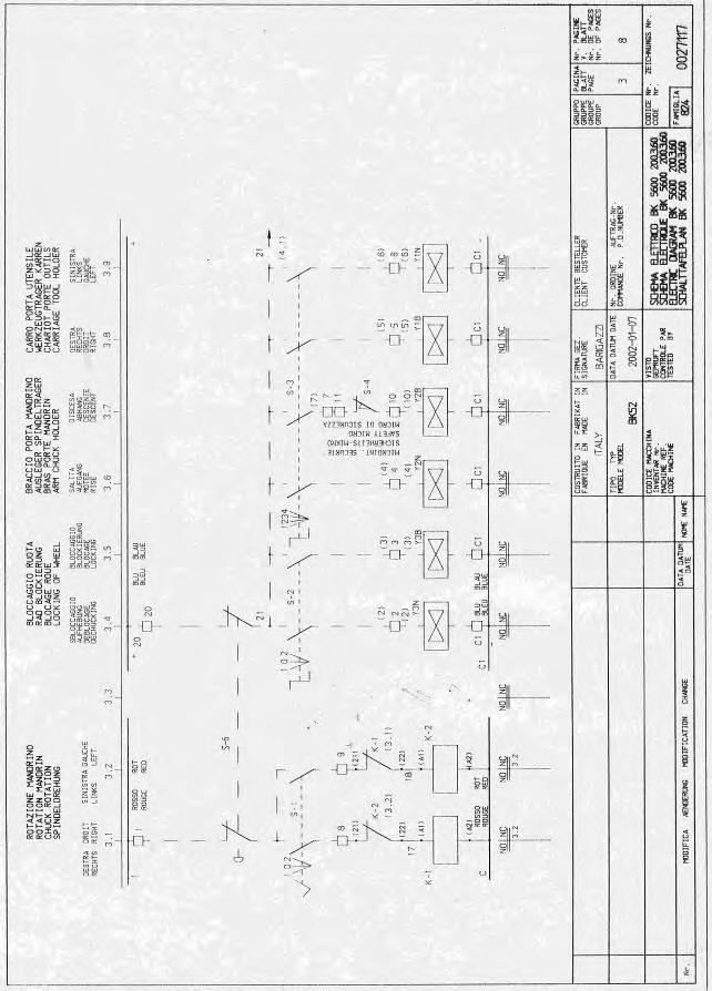
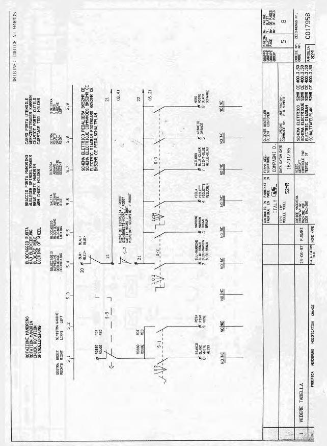
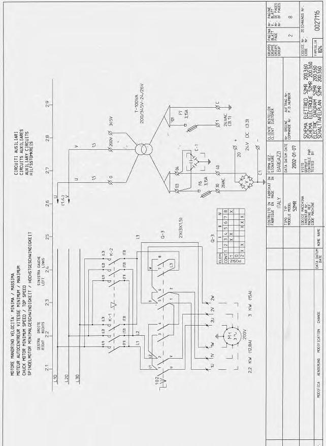
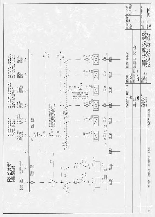
49 4.0 ELECTRIC FUNCTION All King 5600 and 5600R truck tyre changers are equipped by 3 phase motor only. Single phase motors are not available on this style of machines. The machines can be wired at two different voltages: 400 VAC (suitable for V range). 230 VAC (suitable for V range). The chuck motor M (Fig.17) rotation way is controlled by the three polar meters K1 and K2 (Fig.17) while the inverter pole switch Q3 (Fig.17) controlled the speed. The chuck motor is protected by three 25A fuses F1,F2,F3 (Fig.17). On machines for non CE market there is a further circuit breaker Q3 (Fig.24) instead of the fuses F1,F2,F AUXILIARY CIRCUIT The auxiliary circuit controls all movements of the machine. Two wires, U and V, connected to T1 and T2 of the breaker circuit Q2 (Fig.17) supply high power to the transformer T (Fig.17). The transformer transforms the high power in 24VAC and 26VAC. The voltage at which the machine is wired is printed on the serial number plate and on a tag at the end of the power cord. The electric system of the machine is composed by 3 circuits: Power circuit. Auxiliary circuit. Protection circuit. 4.1 POWER CIRCUIT. The power cord has 4 wires: L1,L2,L3 = Phases PE (yellow/green) = Ground The main switch Q1 (Fig.16) controls the power to the machine and it supplies the electric power to the circuit breaker Q2 and to the 25A fuses F1,F2,F3 (Fig.16). The pump motor M (Fig.16) is controlled by the circuit breaker Q2. In case of short circuit or excessive heating, the circuit breaker cuts off the power to the motor. IMPORTANT! The circuit breaker must be regulated following the amperage printed on the label of the pump motor. On CE certified machines only, the circuit breaker is controlled by a coil of minimum tension D1,D2 (Fig.16). It provides to cut off the power to the pump motor in case, for any reason, there is no power on the fuses F2,F3 (Fig.16). 2 Fuses, F4 and F5, of 2A each one (Fig.17) protect the main circuit of the transformer and 2 further fuses,f6 and F7, of 3.15A each one protect the low power circuit. The link converter (Fig.17) is supplied by transformer and it transforms 26VAC in 24VDC to be sent to the coil valves (Fig.18 and 19) for the hydraulic movements. The three polar meters K1 and K2 (Fig. 18), are supplied by the transformer at 24VAC and they control the rotation way of the chuck motor. All movements of the machine are controlled by a remote control where there are 4 switches (Fig.20 and 21): S1 Controls the rotation way of chuck motor (2 pedals). S2 Controls opening and closing of the chuck (2 position switch). S3 Controls chuck arm and saddle movement (8 position switch, 4 position for Hoffmann Japan). S6 Controls the tool holder arm movements (s position switch on King 5600, 4 position switch on King 5600R). 4.3 SAFETY CIRCUIT All machines are equipped by a shut off switch S4 (Fig. 18) on the chuck arm to avoid injuries to personnel or object laying on its pad. The CE certified machines are equipped by an emergency stop switch S5 (Fig. 18), which shut off the 2 auxiliary circuit, 26VAC and 24VDC, in case of emergency. 49
: in case of overheating it disconnects K1 and K2 automatically.")

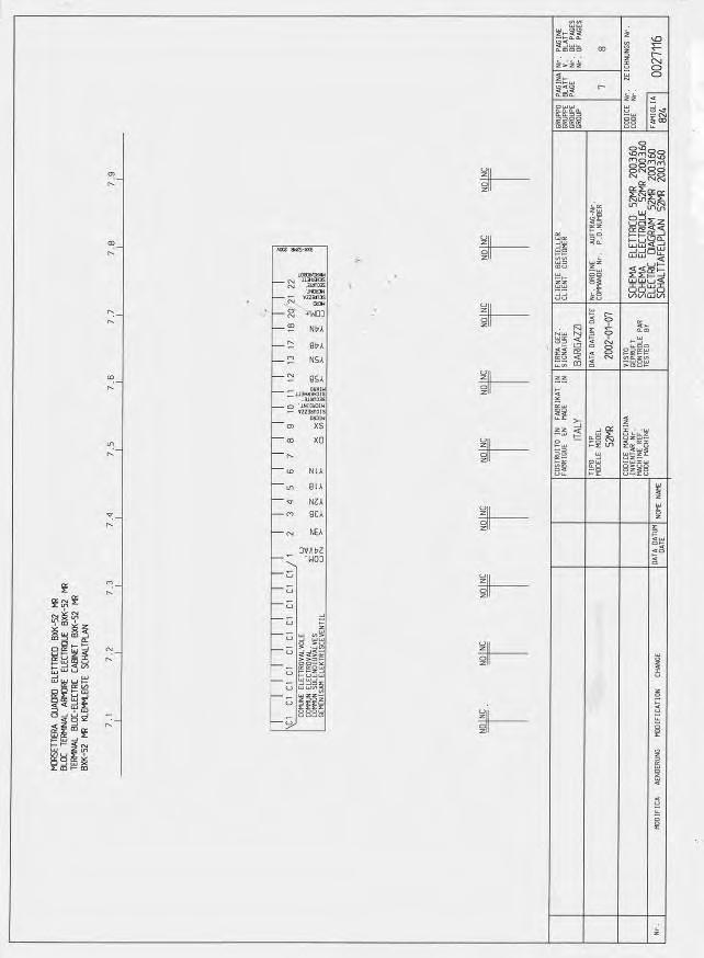
50 The three polar meters K1 and K2, are equipped by a mechanical security (Fig.65) to avoid the starting of both meters simultaneously saving the motor from blowing up. On Ce proved machined the chuck motor is also equipped by a thermostat R1 connected to K1 and K2 (Fig.18): in case of overheating it disconnects K1 and K2 automatically. When the chuck motor is cold the thermostat gets closes and K1 and K2 are reactivated automatically. All King 5600R are also equipped by a safety micro switch S7 on the Robotic assy that locks all hydraulic movements, except the toolholder lifting and lowering, whenever the toolholder hook is not well clamped. 5.0 ACCESS TO ELECTRIC PARTS ELECTRIC BOX: Turn all switches off and open the box by lifting the lever up (Fig.56). Sometimes the opening may result difficult because of door seal sticking. When this happens the door can be easily opened by pulling it with both hands from top and bottom. The electric box contains the following electric components (Fig.57): #1 Main switch Q1 #2 Circuit braker Q2 #3 Coil D1,D2 #4 Fuses F1,F2,F3 #5 Transformer T #6 Fuses F4,F5,F6,F7 #7 Link converter #8 Three polar meters K 1,K2 #9 Control wires terminal #10 Inverter pole switch BEFORE APPROACHING THE ELECTRIC PARTS OF THE MACHINE, DISCONNECT THE MACHINE FROM ELECTRIC SUPPLY. Very often electric failures are only caused by loosened wires or connectors not well fitted. Therefore it is VERY IMPORTANT BEFORE STARTING WITH ANY CONTROL AND/OR REPLACEMENT VERIFY IF ALL WIRES AND CONNECTORS ARE WELL FITTED. To access to electric parts of the machine: Fig.57 PORTABLE CONTROL: Remove the 4 screws from the base and lift up the column (Fig.58). Fig.56 50

. Fig.")


51 Fig.60 Fig.58 8 AND 2 POSITION SWITCHES ASSIES: Remove the screws and pull up the switches (Fig.59, 60 and 61). Fig.61 SAFETY SWITCH: Remove the screws and pull out the yellow assy (Fig. 62). Fig.59 Fig.62 IMPORTANT: WHEN REMOUNTING SWITCHES AND CLOSING THE ELCTRIC BOX DOOR BE CAREFUL NOT TO CRUSH WIRES. 5.1 POWER SUPPLY CABLE AND PLUG: CHECK AND REPLACEMENT 51


52 : 1h : Small and medium screwdriver, medium cross screwdriver, 7mm tube type wrench, faston pliers, scissors, pliers, multimeter. : Defective power supply cable and plug may cause the following malfunction: 1. Turning the switch on the machine does not run at all. TO CHECK THE CABLE: Disconnect power supply. Open the electric box ( 5.0). Remove the yellow protection #1 (Fig.64). Check wires continuity from power supply plug to main switch terminals (Fig.63). Connect the ground wire to ground terminal block. Fix the switch yellow protection. Install plug. Tighten strain relief FIRMLY. IMPORTANT! AT THE END OF THE OPERATION CHECK THE ROTATION WAY OF THE HYDRAULIC MOTOR: IF IT IS WRONG REVERSE TWO PLUG WIRES ONLY. 5.2 MAIN SWITCH Q1: CHECK AND REPLACEMENT : 30 : Medium screwdrivers, medium cross screwdriver, 7mm tube type wrench, pliers. : Defective main switch may cause the following malfunction: 1. Turning the switch on the machine does not run at all. TO CHECK THE SWITCH: Disconnect power supply. Open the electric box ( 5.0). Remove the yellow protection #1 (Fig.64). Fig.63 IMPORTANT! TO CHECK GROUND (YELLOW/GREEN) WIRE, DISCONNECT THE WIRE END FROM THE TERMINAL BLOCK. TO REPLACE THE CABLE: Remove the main switch (Fig.65) and disconnect blue, brown and black wires. Disconnect the ground wire from terminal block. Release cable strain relief on the electric box. Remove plug from cord and take the wrong cable away. Insert the new cable through the strain relief. IMPORTANT! USE ONLY APPROVED CABLES AND PLUGS AND GROUND WIRE MUST BE LONGER THAN THE OTHER ONES. Fig.64 Remove the main switch and disconnect all wires (Fig. 64). Turn switch to Off. Check that there is no continuity (Ω =infinity) between any two terminals L1, L1, L2, L 2, L3 and L 3 ( 4.0). Fix new fastons on inside cable ends and connect them to the switch terminals. Fix the main switch. 52

. Fig.67 IMPORTANT!")

53 Fig.65 Turn switch to On. Check that there is continuity between terminals L1, L1, L2, L 2, L3 and L 3 (Ω = 0 ~ 0,3) and discontinuity between terminals L1, L2, L3 and L1, L2, L3 ( 4.0). If there is continuity the switch is in short circuit and it must be replaced. TO REPLACE THE SWITCH: As the main switch must be removed to be checked, its replacement only requires the removing of the rear support #1 (Fig.66). Install the rear support on the new main switch. Connect wires ends FIRMLY to the new switch terminals as shown in the appropriate electric diagram ( 3.0). Fig.67 IMPORTANT! AT THE END OF THE OPERATION CHECK THE ROTATION WAY OF THE HYDRAULIC MOTOR: IF IT IS WRONG REVERSE TWO SWITCH WIRES ONLY. 5.3 CIRCUIT BREAKER Q2: CHECK AND REPLACEMENT : 30 : Medium screwdriver, pliers, multimeter. : Defective power circuit breaker may cause the following malfunction: 1. Turning the switch on the hydraulic motor does not run at all. 2. Sometimes the breaker shuts off itself suddenly when the machine is operating. IMPORTANT! BEFORE STARTING WITH ANY CONTROL AND REPLACEMENT VERIFY IF THE BREAKER IS CORRECTLY REGULATED COMPARED TO MOTOR DATAS. TO CHECK THE CIRCUIT BREAKER: Turn the machine on. Fig.66 Install the switch on the electric box paying attention to the direction of the spacer #1 (Fig. 67) and mount the yellow protection (Fig.64). MACHINE UNDER TENSION DANGER OF ELECTRIC SHOCK Select the multimeter in VAC. Check voltage between terminals L1and T1, L2 and T2, L3 and T3 of the circuit breaker Q2.If it is not correct the breaker must be replaced. NOTE ONLY FOR CE PROVED MACHINES: If the circuit breaker Q2 cannot be switched on, check the following parts: 53

54 Check if the fuses F2 and F3 are fine ( 5.6). Check if the coil of minimum tension is fine. Check if the hydraulic motor is fine ( 5.7). TO REPLACE THE CIRCUIT BRAKER: Disconnect power supply. Remove all wires from the breaker. IMPORTANT! MARK THE WIRES PROPERLY FOR AN EASY AND SAFE INSTALLATION. Pull downward the tab and lift the breaker up for its removing. Install the new breaker. Connect all wires FIRMLY. Regulate the breaker by turning the wheel #1 (Fig.68) according the amperage printed on the label of the pump motor. TO CHECK THE CABLE: Disconnect power supply. Open the electric box ( 5.0). Disconnect the motor wires from circuit breaker Q2. Remove the motor terminals cover and remove all wires from terminals. Select the multimeter in Ohm and check if there is continuity between ends of each wire. TO REPLACE THE CABLE: Release cable strain relief on the electric box and on the motor. Take the wrong cable away. Insert the new cable through the strain relief. IMPORTANT! : USE ONLY APPROVED CABLE AND GROUND WIRE MUST BE LONGER THAN THE OTHER ONES. NOTE: Before connecting the wires ends, tighten all terminals nuts on the motor. Fix new fastons on inside cable ends and connect them to the motor and breaker terminals. Check the rotation way of the motor: If it is wrong reverse only two motor wires otherwise the chuck motor will turn wrongly. Mount the motor terminals cover. IMPORTANT: WHEN REMOUNTING THE MOTOR TERMINALS COVER BE CAREFUL NOT TO CRUSH WIRES. Fig.68 IMPORTANT! AT THE END OF THE OPERATION CHECK THE ROTATION WAY OF THE HYDRAULIC MOTOR: IF IT IS WRONG REVERSE ONLY THE BRAKER WIRES OTHERWISE THE CHUCK MOTOR WILL TURN WRONGLY. 5.4 HYDRAULIC MOTOR CABLE: CHECK AND REPLACEMENT : 1h : Medium screwdriver, medium cross screwdriver, 7mm tube type wrench, socket head screw 6mm, end wrench 13mm, multimeter, pliers. : Defective cable may cause the following malfunction: 1. Low motor and hydraulic power. 2. Circuit breaker shutting off. 3. Noisy motor. 4. Motor damaging (burning). 5.5 HYDRAULIC MOTOR: CHECK AND REPLACEMENT : 1h : End wrench 13mm, 7mm tube type wrench, 13mm long tube type wrench (Fig.10), medium standard screwdriver, medium cross screwdriver, socket head screw 6 and 3mm, multimeter, amperometic pliers, rubber hammer, calliper. : Defective hydraulic motor may cause the following malfunction: 1. Turning the switch on the hydraulic motor does not run at all. 2. Motor stops when high hydraulic pressure is required. 3. Circuit breaker shutting off. 4. Motor noisy. 5. Turning the switch on the motor turns but the machine does not make any hydraulic movements. IMPORTANT! 54


55 IN CASE OF FAILURE #5 CHECK IF THE ROTATION OF THE MOTOR IS CORRECT AS FIRST. Regulate the scale according to the maximum amperage reported on the motor. Connect the pliers to a wire (Fig.70). TO CONTROL THE MOTOR WHEN IT DOES NOT RUN: Disconnect power supply. Remove the motor terminals cover. Select the multimeter in Ohm and check if there is continuity between terminals U, V and W of the motor (Fig.69). Fig.70 MACHINE UNDER TENSION DANGER OF ELECTRIC SHOCK Fig.69 TO CONTROL THE MOTOR WHEN IT IS NOISY: Disconnect power supply. Remove the motor fan protection and check if the fan is well tightened. Mount the motor fan protection. Remove the motor terminal cover (Fig.69) and verify if all wires are well fitted on terminals. If the wires are well fitted on terminals mount the motor terminals cover and remove the 4 motor screws very carefully: the motor may fall down suddenly. Place the motor on the frame as shown in Fig.71. Switch the motor on and listen it: if it is noisy replace it by following the next step. TO CONTROL THE MOTOR WHEN THE CIRCUIT BREAKER SHUTS OFF. IMPORTANT! BEFORE STARTING WITH ANY CONTROL AND REPLACEMENT VERIFY IF THE BREAKER IS CORRECTLY REGULATED COMPARED TO MOTOR DATAS. Switch the machine on. Make a hydraulic movement and get the pump under pressure. Press the button to lock the value reported by the pliers. Perform the above control on all wires. If the amperage required by one or more phases is 10% higher compared that one reported on the motor tag, increase the breaker adjustment. If the amperage is higher than 10%, the motor must be replaced. TO REPLACE THE MOTOR: Remove all wires from the motor. Remove the 4 motor screws very carefully: the motor may fall down suddenly. Remove the aluminium spacer. Take the distance of joint compared to the motor by using a calliper (Fig.71). Disconnect power supply. Remove the motor terminal cover (Fig.69) and verify if all wires are well fitted on terminals. If the wires are well fitted on terminals take the ammeter pliers. 55


. Open the protection and remove the fuse (Fig.73).")
56 downwards in order to show immediately if there is an inner oil leaking. Mount the motor on the hydraulic assy. Connect the wires FIRMLY to motor terminals following the voltage at which the machine is supplied. NOTE: Before connecting the wires ends, tighten all terminals nuts. Check the rotation way of the motor: If it is wrong reverse only two motor wires otherwise the chuck motor will turn wrongly. Mount the motor terminals cover. IMPORTANT: WHEN REMOUNTING THE MOTOR TERMINALS COVER BE CAREFUL NOT TO CRUSH WIRES. 5.6 FUSES F1, F2, F3: CHECK AND REPLACEMENT Fig.71 Lose the 3mm Allen screws of the joint and remove it from the motor shaft by using two levers (Fig.72). : 30 : Multimeter : Defective fuse/s may cause the following malfunction: 1. Chuck motor does not run at all. TO CONTROL AND REPLACE THE FUSES: Disconnect the machine from power supply. Open the electric box ( 5.0). Open the protection and remove the fuse (Fig.73). Verify if there is continuity between the ends of each fuse. If necessary, replace them with fuses of the same value: 25A 500V. IMPORTANT! ON NON CE PROVED VERSIONS, THE CHUCK MOTOR PROTECTION IS REPLACED BY A CIRCUIT BREAKER ( 5.3). Fig.72 Take the new motor. Mount the joint following the distance previously verified and lock it. IMPORTANT! A WRONG REGULATION OF THE JOINTS WILL CAUSE HYDRAULIC PUMP DAMAGING OR DAMAGING OF JOINTS THEMSELVES WITH A CONSEGUENT NO HYDRAULIC MOVEMENTS. Mount the aluminium spacer: There is a little hole in a face and this face must be mounted Fig.73 56


. Fig.")

57 5.7 INVERTER POLE SWITCH Q3: CHECK AND REPLACEMENT Remove screw shown by the arrow to take out the switch handle (Fig.74). : 1h : Medium and big cross screwdrivers, multimeter. : Defective inverter pole switch may cause the following malfunction: 1. Low chuck power. 2. Noisy motor. 3. Motor damaging (burning). 4. Chuck motor does not run in one or both speeds. TO CHECK THE INVERTER POLE SWITCH: Verify which is the speed that would not work. Remove the chuck motor terminal cover. Switch the machine on. Fig.74 Remove the white spacer (Fig.75). MACHINE UNDER TENSION DANGER OF ELECTRIC SHOCK Turn the inverter switch on the faulty speed. Take the multimeter and select it in VAC. Position the multimeter probes on U1 and W1 of the motor terminals and press the rotation pedal (Fig.73). Fig.75 Remove the screws shown by the arrows to take out the plastic protection and the speed label (Fig.76). Fig.73 The display must show the voltage at which the machine is supplied. If not the switch must be replaced. Perform the same controls with terminals U1- V1 and W1-V1. TO REPLACE THE INVERTER POLE SWITCH: Turn the machine off. Open the electric box. Fig.76 Remove the screws shown by the arrows to get the inverter switch free (Fig. 77 and 78). 57
. 5. Chuck motor does turn in one or both speeds. Fig.77 TO CHECK THE CABLES: Disconnect power supply. Open the electric box ( 5.0).")

58 : 1h : Big and medium cross screwdrivers, 7mm tube type wrench, pliers, multimeter : Defective chuck motor cable may cause the following malfunction: 1. Low chuck power. 2. Noisy motor. 3. Fuses F1,F2,F3 blow up. 4. Motor damaging (burning). 5. Chuck motor does turn in one or both speeds. Fig.77 TO CHECK THE CABLES: Disconnect power supply. Open the electric box ( 5.0). Remove the motor terminals cover and all wires from terminals. Remove the inverter pole switch from the electric box ( 5.7). Select the multimeter in Ohm and check if there is continuity between the ends of each wire of the same cable. TO REPLACE THE CABLE: Release cable strain relief on the electric box and on the motor. Take the wrong cable away. Insert the new cable through the strain relief. Fig.78 Remove the wires from defective inverter switch. Connect the wires to the new switch following the proper electric diagram. Mount the switch on the electric box. Mount the speed label with its plastic protection. Mount the white spacer. Mount the handle. Turn the machine on and check the chuck rotation way in both speed. If the chuck rotation way is not the same in both speeds verify which is the speed at which the chuck motor is turning wrongly. Dismount again the inverter pole switch. Take the electric diagram and reverse two wires of the wrong speed cable. Mount the switch again and check the rotation way again. Mount the chuck motor terminals cover. IMPORTANT: WHEN REMOUNTING THE MOTOR TERMINALS COVER BE CAREFUL NOT TO CRUSH WIRES. 5.8 CHUCK MOTOR CABLES: CHECK AND REPLACEMENT IMPORTANT! USE ONLY APPROVED CABLE AND GROUND WIRE MUST BE LITTLE LONGER THAN THE OTHER ONES. NOTE: Before connecting the wires ends, tighten all terminals nuts on the motor. Fit new fastons on wires ends and connect them to the motor and to the inverter pole switch Q3 terminals. Check if the chuck motor rotation way is correct and if it is the same in both speeds: if the motor change direction changing the speed, take the electric diagram and reverse two wires of the wrong speed cable on the motor only. If the chuck motor turns in wrong direction in both speed, reverse the wires 8 and 9 of the remote control cable on the wire terminal into the electric box ( 5.0). Mount the motor terminals cover. IMPORTANT: WHEN REMOUNTING THE MOTOR TERMINALS COVER BE CAREFUL NOT TO CRUSH WIRES. 5.9 CHUCK MOTOR: CHECK AND REPLACEMENT : 1h 30 58
.")


59 : End wrenches 13,17,19mm, medium cross screwdriver, 7mm tube type wrenches, multimeter, straight bar, extractor,loctite. : Defective chuck motor may cause the following malfunction: 1. Low chuck power. 2. Motor does not run in one or both speed. 3. Fuse/s F1,F2,F3 blowing up. 4. Motor is noisy Lose the 8mm bolt #A (Fig.80). TO CONTROL THE CHUCK MOTOR WHEN IT DOES NOT RUN IN ONE OR BOTH SPEED AND WHEN IT SHOWS LOW POWER: Disconnect machine from power supply. Remove the motor terminals cover. Switch the machine on. MACHINE UNDER TENSION DANGER OF ELECTRIC SHOCK Fig.80 Lose the 4 12mm bolts shown in Fig.81 and remove the belts. Turn the inverter switch on the faulty speed. Take the multimeter and select it in VAC. Position the multimeter probes on U1 and W1 of the motor terminals and press the rotation pedal (Fig.73). If the display shows the voltage at which the machine is supplied the motor must be replaced. Perform the same controls with terminals U1- V1 and W1-V1. TO CONTROL THE MOTOR WHEN IT IS NOISY: Disconnect machine from power supply. Remove the motor terminal cover (Fig.73) and verify if all wires are well fitted. If the wires are well fitted on their terminals, mount the cover and remove the pulleys protections shown in Fig.79. Fig.81 Remove the fan protection and verify if the fan is well tightened on motor shaft. Mount the fan protection, turn the machine on, make it turning and verify if it s noisy. TO REPLACE THE CHUCK MOTOR: Disconnect machine from power supply. Remove all wires from the motor. Remove the chuck motor assy from the chuck arm. Lose the 10mm bolts #C (Fig.80) and remove the motor from its support. Remove the pulley by using an extractor tool (Fig.82). NOTE: The pulley ONLY may be removed from the motor shaft as shown in the picture. Any other system may cause risk of pulley breakage. Fig.79 59
.")
 and the 4 12mm bolts (Fig.81).")
 FIRMLY. Connect the wires FIRMLY to motor terminals following the proper electric diagram. NOTE: Before connecting the wires ends, tighten all terminals nuts. Fig.")
60 Fig.82 Take the new motor. Install the pulley by using rubber hammer and fit its screw by using green loctite. Fig.84 If the clearance is not correct, increase it by turning the nut #1 or decrease it by turning the nut #2 (Fig.85). NOTE: The mounting of the new pulley must be done very carefully in order to avoid motor bearings damaging. Install the motor on its support without lock the bolts #C (Fig.80). Lock the motor support only with 8mm #A (Fig.80) and the 4 12mm bolts (Fig.81). Make pulleys alignment by moving the motor only and using a straight bar as shown in the picture: there must be 1,5 mm between bar and plastic pulley (Fig.83). Fig.85 Lock the 8mm and 12mm bolts (Fig.80 and 81) FIRMLY. Connect the wires FIRMLY to motor terminals following the proper electric diagram. NOTE: Before connecting the wires ends, tighten all terminals nuts. Fig.83 Lock all 4 10mm motor bolts #C (Fig.80). Lose the 8mm bolt #A (Fig.80) and the 4 12mm bolts (Fig.81). Mount the belts Make the belts tension by turning the 12mm nuts (Fig.81). When the belt tension is done, make sure that there are still 1,5mm between bar and plastic pulley (Fig.84). Check if the chuck motor rotation way is correct and if it is the same in both speeds: if the motor change direction changing the speed, take the electric diagram and reverse two wires of the wrong speed cable on the motor only. If the chuck motor turns in wrong direction in both speed, reverse the wires 8 and 9 of the remote control cable on the wire terminal into the electric box ( 5.0). Mount the motor terminals cover. IMPORTANT: WHEN REMOUNTING THE MOTOR TERMINALS COVER BE CAREFUL NOT TO CRUSH WIRES. Mount the belts protections. 60


61 NOTE: After mounting the protection turn the chuck to verify if there is contact between pulleys and their protections. In case of contact, the pulleys make noise, the protection need to be readjusted until to have chuck rotation without any noise TRANFORMER: CHECK AND REPLACEMENT : 30 : Multimeter, small and medium cross screwdrivers, pliers. : Defective transformer may cause the following malfunction: 1. Smoke gets out from the electric box with consequent burning of the transformer. 2. Turning the machine on, the hydraulic motor run but the machine does not make any movement. TO CONTROL THE TRANSFORMER: Take the multimeter and select it in VAC. Switch the machine on. MACHINE UNDER TENSION DANGER OF ELECTRIC SHOCK Verify if the power between terminals 0 and 400 or 230, according to voltage at which the machine is supplied, is correct (Fig.86): if not see 5.1 and 5.2. Verify if there is power between terminals 0 and 24 and between terminals 0 and 26 (Fig.86). TO REPLACE THE TRANFORMER: Fig.86 IMPORTANT! MARK WIRES PROPERLY FOR AN EASY AND SAFE INSTALLATION. Lose its four screws. Pull the transformer up and take it out. Install the new transformer and tighten firmly all wires FUSES F4,F5,F6,F7: CHECK AND REPLACEMENT : 30 : Multimeter. : Defective fuse/s may cause the following malfunction: 1. Turning the machine on, the hydraulic motor run normally but the machine does not make any movement. TO CONTROL AND REPLACE THE FUSES: Disconnect the machine from power supply. Open the electric box ( 5.0). Open the protection and remove the fuse (Fig.87) Disconnect the machine from power supply. Open the electric box ( 5.0). Remove all wires from terminals. Fig.87 61
 F5= 2A 250V (4A for supplied at 200V) F6= 3,15A 250V F7= 3,15A 250V Fig.")

62 Take a multimeter and select it in Ohm. Verify if there is continuity between the ends of each fuse. If necessary, replace them with fuses of the same values: F4= 2A 250V (4A for supplied at 200V) F5= 2A 250V (4A for supplied at 200V) F6= 3,15A 250V F7= 3,15A 250V Fig.89 TO REPLACE THE CONVERTER: Disconnect the machine from power supply. Open the electric box ( 5.0). Remove all wires from the converter. Fig LINK CONVERTER: CHECK AND REPLACEMENT : 30 : Multimeter, Medium cross screwdriver : Defective rectifier may cause the following malfunction 1. Turning the machine on, the hydraulic motor run but the machine does not make any movement. TO CONTROL THE CONVERTER: Switch the machine on. Take the multimeter and select it in VAC. MACHINE UNDER TENSION. DANGER OF ELECTRIC SHOCK Position the multimeter probes on the red terminals of the converter and verify if the power displayed by the multimeter is 26 VAC (Fig.89). Position the multimeter probes on the blue terminals of the converter and verify if the power displayed by the multimeter is 24 VDC (Fig.89) : if not replace the converter. IMPORTANT! MARK WIRES PROPERLY FOR AN EASY AND SAFE INSTALLATION. Loosen the defective converter and replace it with a new one. Fit all wires again. Check if the machine works normally THREE POLAR METERS K1,K2: CHECK AND REPLACEMENT : 30 each one : Medium screwdriver, medium cross screwdriver, pliers. : Defective contactor K1 or K2 may cause the following malfunction: 1. Chuck does not turn in one direction or both direction. 2. Low chuck power in one or both direction. 3. Noisy motor. 4. Burning of the motor. A. TO CONTROL THE METERS: Disconnect the machine from power supply. Open the electric box ( 5.0). Take the multimeter and select it in Ohm. Press the black buttons on top of the meter K1 and verify if there is continuity between L1- T1, L2-T2, L3-T3 (Fig.90). Repeat the same operation with K2. B. TO CONTROL THE COIL: Switch the machine on. Take the multimeter and select it in VAC. 62

. Remove all wires from terminals. IMPORTANT!")

63 Fig.90 MACHINE UNDER TENSION. DANGER OF ELECTRIC SHOCK Fig.91 Position the multimeter probes on A1 and A2 of the meter and press the correspondent rotation pedal on the remote control: The multimeter must display 24 VAC. If the multimeter shows the correct voltage but the coil does not get exiting, it means that the coil is defective and it must replaced. TO REPLACE THE METER: Disconnect the machine from power supply. Remove mechanical safety from meters by pulling the locking safety lever in direction 1 and lifting it up 2. (Fig.91). Remove all wires from terminals. IMPORTANT! MARK WIRES PROPERLY FOR AN EASY AND SAFE INSTALLATION. Pull downward the tab and lift the meter up for its removing (Fig.92). Install the new meter. Connect all wires FIRMLY. Mount the mechanical safety. Fig PORTABLE CONTROL CABLE: CHECK AND REPLACEMENT : 2h 30 : Small and medium screwdriver, medium cross screwdriver, tube type wrenches 7 and 10mm, end wrenches 10 and 14mm : Defective portable cable may cause the following malfunction: 1. Machine does not make one or more movements. 2. Sometimes the machine does not make one or more movements. 3. Fuses F6 and F7 blow up. IMPORTANT! FAILURE #1 MAY ALSO BE CAUSED BY HYDRAULIC PROBLEM. TO VERIFY IF THE 63

. Remove the wires cover (Fig.94). Fig.96 TO REPLACE THE CABLE: Fig.")
 and the second one on the supposed defective wire.")
. Remove all wires from all micro switches Remove the defective cable from the portable control.")
64 FAILURE IS ELECTRIC OR HYDRAULIC PRESS THE COIL VALVE CORRESPONDENTS TO THE DEFECTIVE HYDRAULIC MOVEMENT (Fig. 93). IF THE MACHINE WORKS NORMALLY BY PRESSING THE COIL VALVE, THE PROBLEM IS DUE TO AN ELECTRIC MALFUNCTION. Fig.95 If there is not continuity remove the suspected wrong wire from the correspondent micro switch and verify if there is continuity between the two ends of the same wire. Fig.93 TO CONTROL THE CABLE: Disconnect the machine from power supply. Open the electric box ( 5.0). Remove the wires cover (Fig.94). Fig.96 TO REPLACE THE CABLE: Fig.94 Remove all portable control wires from terminals block (Fig.95). Take a multimeter and select it in Ohm. Position a multimeter probe on a common end (the n 1 is for the rotation pedals and the n 20 is for hydraulic commands) and the second one on the supposed defective wire. Press the correspondent command on the portable control and verify if there is continuity between the two ends (Fig.96) Disconnect the machine from power supply. Open the electric box ( 5.0). Remove all remote control wires from terminals block (Fig.94). Remove all wires from all micro switches Remove the defective cable from the portable control. Connect by tape the old cable with the new one to insert the new cable through the inner cabinet holes. Release cable strain relief on the electric box. Take the defective cable away. Insert the new cable through the strain relief. Connect all wires FIRMLY to the terminals block of the electric box, following the numbers reported on each one. Tighten the cable strain relief. Insert 3 steel wires through 8 and 2 position switches and, only on CE proved machines, emergency switch seats in order to drive easily the new wires to the correct direction inside of the portable control. Tighten the rotation wire FIRMLY to their switches in the bottom of the portable control. 64

. Fig.97 Press the pedals all way down: they do not have contact with the switches bodies.")

65 Mount the rotation switches on their support and tighten handily the nuts With pedals in rest position, leave 5mm of clearance between them and the switches (Fig.97). Pull up all steel wires simultaneously until to get all wires out. Remove the steel wires from the rest of the wires. Connect all wires to the switches. IMPORTANT: THE WIRES MUST BE FITTED ON THE MICRO SWITCH IN OPPOSITE POSITION COMPARED TO THE DRAWING REPORTED ON 8 AND 2 POSITION SWITCH. COMAND WIRES MUST BE FITTED ON PLUG #1 WHILE THE COMMON ONES MUST BE FITTED ON MIDDLE PLUG #2 (Fig.99). Fig.97 Press the pedals all way down: they do not have contact with the switches bodies. In case of contact increase the previous 5mm clearance (Fig.98) Make some turns of tape around the 8 and 4 position switches (Fig.62) in order to avoid short circuit. Install the cable strain relief in the bottom of the portable control and tighten the ground wire FIRMLY. Fit the column to the base. Fit 8,4 and 2 position switch and the emergency switch. IMPORTANT: WHEN REMOUNTING COLUMN ON THE BASE BE CAREFUL NOT TO CRUSH WIRES. Fig.98 Tighten the nuts FIRMLY. Connect by using tape, the wires 4,5,6,7 and the 4 commons ones all together connected, to the steel wire coming from the 8 position switch previously inserted. On King 5600R connect the wires 12,13,17,18 and further 4 common wires to the steel wire from 4 position switch. Connect by using tape, the wires 2,3 and 2 commons all together connected, to the steel wire coming from 2 position switch. On King 5600 connect wires 12,13 and two further common wires to the steel wire from the second 2 position switch. Connect the rest of the wires to the third steel wire. Fig.99 Check if the machine works fine. If the machine start to work alone when switching on, it means that command wire/s is/are reversed with the common one/s. Verify which is the movement, dismount the 65
66 correspondent switch holder and reverse the wires. Check the machine again SWITCHES S1: CHECK AND REPLACEMENT : 30 each one : Medium screwdriver, tube type wrench 10mm, end wrench 14mm : Defective switch/es S1 and S2 may cause the following malfunction: 1. The chuck does not turn in one or both ways. 2. Fuse F7 blows up. TO CONTROL THE SWITCHES: If the wires are fine ( 5.14) the switches S1 need to be checked. Take the multimeter and select it in Ohm. Position the multimeter probes on the contacts where the wires were fitted. Press by hand the switch and verify if there is continuity: If not the switch must be replaced. TO REPLACE THE SWITCHES: To replace the defective switch loose its screws and fix the new one following the instruction ( 5.14) MICRO SWITCHES S2, S3, AND S6: CHECK AND REPLACEMENT : 30 each one : Small and medium cross screwdriver. : Defective switches S2, S3 and S6 may cause the following malfunction: 1. One or more hydraulic movements do not work. 2. Fuse F6 blows up. 3. Switching the machine on one or more movements starts automatically. IMPORTANT! FAILURE #1 MAY ALSO BE CAUSED BY HYDRAULIC PROBLEM. TO VERIFY IF THE FAIULURE IS ELCTRIC OR HYDRAULIC PRESS THE COIL VALVE CORRESPONDENTS TO THE DEFECTIVE HYDRAULIC MOVEMENT (Fig. 93). IF THE MACHINE WORKS NORMALLY BY PRESSING THE COIL VALVE, THE PROBLEM IS DUE TO AN ELECTRIC MALFUNCTION. TO CONTROL THE SWITCHES: Position the multimeter probes on the contacts where the wires were fitted. Press by hand the switch and verify if there is continuity: If not the switch must be replaced. TO REPLACE THE SWITCH: To replace the defective switch loose its screws and fix the new one following the instruction ( 5.14) MICRO SWITCHES S2, S3, AND S6 HOLDERS: CHECK AND REPLACEMENT : 1h : Small and medium cross screwdriver, big standard screwdriver, pliers, loctite. : Defective switches holders may cause the following malfunction: 1. One or more hydraulic movements do not work. 2. The holders are damaged or broken. TO CHECK THE HOLDERS: Disconnect power supply from machine. Remove the holder/s from the portable control. Remove the tape from the 8 or 4 position switch assy. Move the lever and check if the switches make a click sound when they are pressed. IMPORTANT! THE SWITCHES CLICK MUST BE GOT WITHOUT MAKE ANY OVERPRESSURE ON THE HOLDERS HANDLE. TO REPLACE THE 2 POSITION HOLDERS: Remove all wires and micro switches from their holder. Remove the wires and the switches. Install switches and wires on the new holder ( 5.14). IMPORTANT! THE WIRES MUST BE FITTED ON THE MICRO SWITCH IN OPPOSITE POSITION COMPARED TO THE DRAWING REPORTED ON 2 POSITION SWITCH. COMAND WIRES MUST BE FITTED ON PLUG #1 ONLY WHILE THE COMMON ONES MUST BE FITTED ON MIDDLE PLUG #2 ONLY (Fig.100). If the wires are fine ( 5.14) the switches S2, S3 and S6 need to be checked. Take the multimeter and select it in Ohm. 66
 TO REPLACE THE 8 OR 4 POSITION HOLDERS: Remove all wires and micro switches from their holder. Remove the top cover. IMPORTANT!")


67 Fig.100 Verify if it works fine. Fit the assy on the portable control. Fig.102 Verify if all components are fine (Fig.103) TO REPLACE THE 8 OR 4 POSITION HOLDERS: Remove all wires and micro switches from their holder. Remove the top cover. IMPORTANT! BEFORE STARTING WITH ANY DISMOUNTIG OPERATION VERIFY BY USING SCREWDRIVER IF THE HANDLE IS WELL TIGHTENED (Fig.102). IF IT IS LOOSENED DISMOUNT THE COMPLETE HANDLE AND MOUNT IT AGAIN BY USING LOCTITE ON THE THREAD. Remove the seeger ring #1 and the rubber protection #2 (Fig.101) Fig.103 Take the new holder. Install the pins, the spacer and the spring on the new holder by using loctite on the thread. Install the rubber protection #2 and the seeger ring #1 (Fig.101). Install the micro switches. Install the top cover. Make some turns of tape all around the 8 or 4 position switch to avoid short circuit. Verify if it works fine Mount the assy on the portable control SHUT OFF CABLE: CHECK AND REPLACEMENT Fig.101 Remove the pins, the spacer and the spring from the holder (Fig.102). : 1h : Small standard screwdriver, medium cros screwdriver, multimeter, pliers. : Defective cable may cause the following malfunction: 1. The chuck arm does not come down. 2. Fuse F7 blows up. IMPORTANT! 67

. Release the strains cable relief on electric box. Take the defective cable away. Insert the new cable. Tighten the wires on the switch S4 and on the terminals block FIRMLY.")
68 FAIULURE #1 ALSO MAY BE CAUSED BE A MECHANICAL MALFUNCTION OF THE SHUT OFF SWITCH PROTECTION. BEFORE STARTING WITH ANY ELECTRICAL CONTROL VERIFY IF THE PROTECTION IS WELL REGULATED AND IF IT MOVES UP AND DOWN FREELY. TO CONTROL THE CABLE: Disconnect the machine from power supply. Open the electric box ( 5.0). Disconnect the wires 10 and 11 from terminal block into electric box (Fig.104). Disconnect the wires 10 and 11 from terminal block. Open the shut off switch S4 cover and disconnect both wires (Fig.105). Release the strains cable relief on electric box. Take the defective cable away. Insert the new cable. Tighten the wires on the switch S4 and on the terminals block FIRMLY. Lock the switch S4 cover and tighten the screws FIRMLY. IMPORTANT: WHEN CLOSING THE SWITCH DOOR BE CAREFUL NOT TO CRUSH WIRES. Tighten the strain cable relief leaving some cable free (Fig.105) SHUT OFF SWITCH S4: CHECK AND REPLACEMENT Fig.104 Open the shut off switch S4 cover and disconnect both wires (Fig.105). Take a multimeter and select it in Ohm. Position the multimeter probes on the ends of same wire and verify if there is continuity (Ω = 0 ~ 0,3). If there is not continuity the wire must be replaced. : 1h : Small standard screwdriver, multimeter, pliers, end wrench 13mm, Allen wrench 4mm, loctite. : Defective shut off switch may cause the following malfunction: 3. The chuck arm does not come down. 5.0 Fuse F7 blows up. IMPORTANT! FAIULURE #1 ALSO MAY BE CAUSED BY A MECHANICAL MALFUNCTION OF THE SHUT OFF SWITCH SAFETY LEVER. BEFORE STARTING WITH ANY ELECTRICAL CONTROL VERIFY IF THE PROTECTION IS WELL REGULATED AND IF IT MOVES UP AND DOWN FREELY. TO CONTROL THE SWITCH: Fig.105 TO REPLACE THE CABLE: Disconnect the machine from power supply. Open the electric box ( 5.0). Disconnect the machine from power supply. Open the electric box ( 5.1). Disconnect the wires 10 and 11 from terminal block. Open the shut off switch S4 door and disconnect both wires (Fig.105). Take a multimeter and select it in Ohm. Position the multimeter probes on the switch terminals and verify if there is continuity (Ω = 0 ~ 0,3). If there is not continuity the switch must be replaced. TO REPLACE THE SWITCH: Release the strain cable relief on chuck arm. Remove the defective switch. Install the new switch. 68

.")
. Verify if the shut off protection is moving up and down freely with chuck arm completely lowered (Fig.106). Fig.107 Fig.")

69 Tighten the wires on the switch S4 FIRMLY. Lock the switch S4 cover and tighten the screws FIRMLY. IMPORTANT: WHEN CLOSING THE SWITCH DOOR BE CAREFUL NOT TO CRUSH WIRES. Tighten the strain cable relief leaving some cable free. NOTE: LEAVE 2mm OF CLEARANCE BETWEEN SWITCH S4 AND ITS SAFETY LEVER IN ORDER TO AVOID STOPPING OF THE CHUCK ARM DURING THE LOWERING OPERATION. Do the same control on the blue terminals. If there is not continuity the switch must be replaced. TO REPLACE THE SWITCH S5: Loosen the screws #1 until to have switch very free(fig.107). Loosen the metal ring #1 and turn the red button #2 (Fig.108) counter clockwise for a quarter of a turn pull it up to take it off. The red button is now separated from the rest of the switch (Fig.109). Verify if the shut off protection is moving up and down freely with chuck arm completely lowered (Fig.106). Fig.107 Fig EMERGENCY SWITCH S5: CHECK AND REPLACEMENT : 1h : End wrench 8mm, tube type wrench 8mm, small standard screwdriver, small cross screwdriver, multimeter. : Defective switch S5 may cause the following malfunction: 1. Switching the machine on the hydraulic motor turns but the machine does not work. Fig.108 TO CONTROL THE SWITCH: Remove power supply from the machine. Remove the yellow assy from portable control ( 5.0 Fig.62). Take a multimeter and select it in Ohm. Leave the red emergency button unlocked Position the multimeter probes on the red terminals wires and verify if there is continuity (Ω = 0 ~ 0,3) (Fig.107). Fig
. Switch the machine on and verify if it works fine. Fix the yellow assy to the portable control.")

. TO CHECK THE CABLE: Disconnect the machine from power supply. Open the electric box ( 5.0).")
. Take a multimeter and select it in Ohm. Verify if there is continuity between two ends of the same wire.")
70 Remove the wires. Take the new switch and fix the wires. Fix the red button by pressing and turning it clockwise for a quarter of a turn. Tighten the metal ring. Tighten the screws #1 (Fig.107). Switch the machine on and verify if it works fine. Fix the yellow assy to the portable control. IMPORTANT: WHEN FIXING THE SWITCH ASSY TO THE PORTABLE CONTROL, BE CAREFUL NOT TO CRUSH WIRES ROBOTIC SAFETY SWITCH CABLE: CHECK AND REPLACEMENT : 1h : Small standard and cross screwdrivers, 3mm allen wrench, 6mm end wrench, pliers, multimeter. : Defective cable may cause the following malfunction: 1. All hydraulic movements, except tool holder lifting and lowering, do not work. Fig.111 TO REPLACE THE CABLE: Lose cable strein relief (Fig.112). TO CHECK THE CABLE: Disconnect the machine from power supply. Open the electric box ( 5.0). Disconnect the wires from terminal block 20 and 21 (Fig.110). Fig.112 Lose the nut shown in Fig.113 and remove the switch from its support. Fig.110 Remove the robotic safety switch cover (Fig.111). Take a multimeter and select it in Ohm. Verify if there is continuity between two ends of the same wire. If one or both wires do not show continuity, the cable must be replaced. Fig

 Remove the 2 bolts shown by the arrows and take away the protection (Fig.")


.")
71 Disconnect the wires from the switch. Cut the clip hoses and remove the switch cover (Fig.114). Fig.116 Fig.114 Regulate the switch in order to have its wheel as closest as possible to the machined safety rod but leaving it free (Fig.117) Remove the 2 bolts shown by the arrows and take away the protection (Fig.115). Fig.117 Fig.115 Remove all plastic protections. Take away the defective cable. Insert the new cable. Connect the cable to the robotic switch. Mount the switch on its support in order to have all movements running. Connect the cable to the terminal block 20 and 21 into the electric box. Turn on the machine and open the saddle until end of the stroke (Fig.115). Lift up the tool holder till to have the switch wheel on the machined size of the safety rod (Fig.116). Lock the switch nuts FIRMLY. Lower the tool holder a little and check if all movements are locked: If not decrease a little the clearance between switch wheel and machined safety rod by moving the switch as shown by arrow (Fig.118). Fig
.")


72 Lower all way down the tool holder till to have its cylinder at the end of the stroke: all function of the machine should work normally. If not move a little the switch by following the arrow in Fig.119. Fig.121 Check if the machine works fine. Fig.119 Tighten the cable strein relief. Mount the switch cover and fit the hoses with a clip hose (Fig.114). IMPORTANT: WHEN FIXING THE SWITCH COVER, BE CAREFUL NOT TO CRUSH WIRES. Move the tool holder till end of the stroke and leave some hoses free (Fig.120) 5.22 ROBOTIC SAFETY SWITCH : CHECK AND REPLACEMENT : 1h : Small standard and cross screwdrivers, 3mm allen wrench, 6mm end wrench, pliers, multimeter. : Defective switch may cause the following malfunction: 1. All hydraulic movements, except tool holder lifting and lowering, do not work. TO CONTROL THE SWITCH: Switch the machine on. Lower the tool holder arm and hook it. Make sure to have the hook cylinder at the end of stroke. Turn off the machine and open the electric box. Disconnect the wires 20 and 21 from terminal block (Fig.110). Take the multimeter and select it in Ohm. Verify if there is continuity between the wires 20 and 21. If there is not continuity the switch must be replaced. IMPORTANT! BEFORE STARTING WITH SWITCH REPLACEMENT VERIFY IF IT IS WELL REGULATED AND VERIFY IF THE WIRE IS FINE. Fig.120 Lock the hoses on their protection and mount the rubber tube (Fig.121) Install the protection (Fig.115). Mount the plastic spring around the hoses. TO REPLACE THE SWITCH: Replace the switch following COIL CONNECTOR CABLE: CHECK AND REPLACEMENT 72
. Remove the coil valve protection (Fig.122).")
. Take away the defective cable. Insert the new cable.")

73 : 1h : Small standard and cross screwdrivers, pliers, multimeter. : Defective cable or connector may cause the following malfunction: 1. One or more hydraulic movements do not work. 2. Fuse F7 blows up. TO CONTROL THE CABLE: Disconnect the machine from power supply. Open the electric box ( 5.0). Remove the coil valve protection (Fig.122). VERIFY IF THE WIRES ARE FITTED ON THEIR TERMINALS. IF THEY AREN T TIGHTEN THEM FIRMLY TO THE TERMINALS, MOUNT THE CONNECTOR AGAIN AND VERIFY IF THE MACHINE WORKS FINE. IF THE PROBLEM IS STILL NOT SOLVED PROCED FOLLOWING THE BELOW INSTRUCTION. Remove all wires from connectors (Fig.125). Take away the defective cable. Insert the new cable. Tighten all wires FIRMLY on the terminals block and on the coil connectors. Tighten the cable strains relief. Fix the connectors to the coil valve following the correct order. Fig.122 Remove all coil connector from coil valves. Take a multimeter and select it in Ohm. Position the multimeter probes on the ends of the coil connector (Fig.123) and verify if there is continuity between the terminals: If there is not continuity the wires are defective. Fig.124 Fig.125 Fig.123 TO REPLACE THE CABLE: Disconnect all wires from the terminals block. Disconnect all connectors from coil valves. Release the cable strains relief. Lift up the connectors by using a screwdriver to have access to the wires (Fig.124). IMPORTANT! 6.0 HYDRAULIC FUNCTION The hydraulic working pressure at which each machine is carefully regulated is 160 Bar (2300 P.S.I) and it is reported on the sticker label. The hydraulic system is composed by two different circuits: High pressure circuit at 160 Bar (2300 psi). Low pressure circuit at 60 Bar (860 psi). 73
74 6.0.1 HIGH PRESSURE CIRCUIT: The high hydraulic pressure is controlled by the valve 0.5 (Fig.52) and its range is from 50 to 200Bar (720 to 2880Psi). This valve avoids overstress to hydraulic and mechanical components. The working of this valve is very easy: when the hydraulic pressure inside of a cylinder reaches 160 (2300 P.S.I.), the valve opens and unloads the oil directly into the reservoir. The cylinders operating at high pressure are the following: Saddle cylinder. Chuck arm cylinder. Chuck cylinder LOW PRESSURE CIRCUIT: The low hydraulic pressure is controlled by the valve 4.1 (Fig.52) and its range is from 0 to 100Bar (0 to 1440Psi). The working of this is the same of above one and its purpose is to supply the minimum hydraulic pressure to allow the tool holder movements. The cylinder operating at low pressure are the following: Tool holder cylinder. Robotic cylinder on King 5600R only. NOTE: ALL HYDRAULIC CYLINDERS ARE DOUBLE ACTING TYPE DESCRIPTION OF THE FUNCTION: The description of the hydraulic function can be grouped into 7 phases as following: Machine in rest position. Rise and descent of chuck arm. Left and right of saddle. Opening and closing of the chuck. Left and right the tool holder Rise and descent of the tool holder cylinder ON KING 5600R ONLY Double movements MACHINE IN REST POSITION: When the machine is switched on but not operating, the hydraulic oil (Fig.52) is pumped through all valves in rest position, and then it returns to the reservoir LEFT / RIGHT OF CARRIAGE: LEFT: Oil flow reaches the side B of the cylinder 1.4 through the valve Y1B. Oil in opposite side A gets out and returns to reservoir through the valvey1n (Fig.52). RIGHT: Oil flow reaches the side A of the cylinder 1.4 through the valve Y1N. Oil in opposite side B gets out and returns to reservoir through the valve Y1B (Fig.52) RISE AND DESCENT OF CHUCK ARM: RISE: The oil flow arrives to the valve Y2B, which is opened, and unlocking the valve 2.5, it reaches the side B of the cylinder 2.7 making the wheel lifting. Oil contained in opposite side A, returns to the reservoir through all others valves. Safety valve 2.5 prevents any unexpected chuck arm lowering from oil hose breakage or defective coil valve (Fig.52). DESCENT: Oil flow, before reaching the side A of cylinder 2.7 through the valve Y2N, is forced to the safety valve 2.5 to get its unlocking. Oil contained in opposite side B, gets out through the valve 2.2, which control the lowering speed of the chuck arm, and returns to reservoir through all other valves (Fig.52). NOTE: THE SAFETY VALVE 2.5 IS INSTALLED ON CE PROVED MACHINES ONLY OPENING AND CLOSING OF THE CHUCK: OPENING: Oil flow reaches the side A of the cylinder 3.5 through the valve Y3N and when the cylinder has reached the maximum pressure, the locking valve 3.4 avoids dropping of hydraulic pressure. CLOSING: The oil flow is forced to the locking valve 3.4 through the valve Y3B to get its unlocking. Oil contained in the side B of the chuck cylinder 3.5 returns to the reservoir through all other valves (Fig.52) LEFT / RIGHT OF TOOL HOLDER: LEFT: Oil flow reaches the side B of the cylinder 4.5 through the valve Y5B. Oil in opposite side A gets out and returns to reservoir through the valvey5n (Fig.52). 74

. IMPORTANT!")
75 RIGHT: Oil flow reaches the side A of the cylinder 4.5 through the valve Y5N. Oil in opposite side B gets out and returns to reservoir through the valve Y5B (Fig.52) RISE AND DESCENT OF ROBOTIC: RISE: The oil flow reaches the side B of the cylinder 5.5 through the valve Y4N making the robotic lifting. Oil contained in opposite side A, returns to the reservoir through all others valves. DESCENT: Oil flow reaches the side A of cylinder 5.5 through the valve Y4B making the robotic lowering. Oil contained in opposite side B, gets out through the valve Y4N and returns to reservoir through all other valves (Fig.52). IMPORTANT! BEFORE APPROACHING THE HYDRAULIC PARTS OF THE MACHINE, DISCONNECT THE MACHINE FROM ELECTRIC SUPPLY. IN CASE OF OIL LEAKING DRY CAREFULY THE FLOOR TO AVOID SLIPAGE. HYDRAULIC ASSY: Remove the top cover (Fig.122) and the whole assy is available (Fig.126) DOUBLE MOVEMENTS: Oil flow can reach simultaneously more valves moving more cylinders and making faster operations. As soon as one or more cylinders reach the end of their stroke, machine stops all movements because the valves 0,5 or that one 4.1 open and unload the oil to the reservoir. 6.1 ACCESS TO HYDRAULIC PARTS The access to the hydraulic parts of the Boxer King 2600 is more complicated compared to the electric ones, because in some cases the dismounting of many parts is required to reach those defective. The most important controls are those ones concerning the different hydraulic pressures at which each cylinder of the machine is working. Fig.126 KING 5600R SADDLE CYLINDER: To access to this cylinder (Fig.128) remove the black cover (Fig.127). This controls allow to find out very quickly the reason of any hydraulic malfunction. Another of the purpose of this manual is to reduce as much as possible the oil leaking during the maintenance operation: this will allow to operate on the machine in clean and safe condition. Before approaching the hydraulic parts, the following material needs to be prepared: 2 oil containers: 1 for hydraulic oil and 1 for gear oil. Oil absorber. Paper towels. Fig
 remove the red hoses protection (Fig.129). Fig.")
 is included into the chuck arm and its access is the most")


, requires the dismounting of the cabinet-tool holder cabinet")
76 Fig.128 KING 5600 SADDLE CYLINDER: To access to this cylinder (Fig.130) remove the red hoses protection (Fig.129). Fig.131 CHUCK CYLINDER: This cylinder (Fig.132) is included into the chuck arm and its access is the most complicated one because it requires the dismounting of the gear oil tank, the worm screw assy and chuck components. So far the chuck cylinder has required the replacement of the seals only. Fig.129 Fig.132 Fig.130 TOOL HOLDER CYLINDER: The access to this cylinder (Fig.135), requires the dismounting of the cabinet-tool holder cabinet (Fig. 133 and 134). CHUCK ARM CYLINDER: The access to this cylinder does not require any dismounting of any protection (Fig.131). 76


77 Fig.133 Fig.136 To dismount the cabinet tool holder on the King 5600 remove the 14mm nut in Fig.137 and then those ones of 10mm in Fig.138. Fig.134 To dismount the cabinet tool holder on the King 5600 remove the 14mm nut in Fig.135 and then that one of 20mm in Fig.136. Fig.137 NOTE: SOMETIMES THERE ARE SHIMS BETWEEN CABINET AND NUT. THESE SHIMS MUST BE PLACED AGAIN IN THE SAME POSITION. Fig.138 Fig


 requires the dismounting of the hook protection (Fig.140).")


78 6.2 HYDRAULIC OIL LEVEL: CHECK AND LEVELLING : 30 : Suggested hydraulic oil. : Incorrect oil level may cause the following malfunction: 1. Slow or no hydraulic movements. 2. Possible pump damaging. TO CHECK THE HYDRAULIC OIL LEVEL: Fig.139 ROBOTIC CYLINDER: The access to this cylinder (Fig.141) requires the dismounting of the hook protection (Fig.140). Switch the machine on. Close all cylinders. Switch the machine off. Remove the reservoir stopper. Verify if oil level corresponds to mark #1 of the stopper rod (Fig.142) Fig.140 Fig.142 TO MAKE THE OIL LEVEL: Take the suggested hydraulic oil, reported on a sticker tag on the reservoir and on the user manual, and fill the reservoir until to reach the mark on the stopper rod. IMPORTANT! Fig USE SUGGESTED HYDRAULIC OIL ONLY AS REPORTED ON THE USER MANUAL. 78

. Fig.")
. Fig.143 Open the jaws and put the chuck cylinder under pressure.")
79 2. DO NOT OVERFILL THE RESERVOIR BECAUSE THE OIL IN EXCESS WILL COME OFF THROUGH THE STOPPER WHILE MACHINE IS OPERATING. The hydraulic oil does not need to be replaced: It only must be refilled. 6.3 HIGH PRESSURE HYDRAULIC CIRCUIT: CHECK AND ADJUSTMENT : 30 : End wrenches 10,13,19 and 24mm, allen wrenches of 3 and 6mm, manometer. : This is the first operation to be done when there is the suspects of hydraulic problem. TO CHECK THE PRESSURE: Switch the machine on and close the jaws. Turn the machine off Install he manometer on the chuck cylinder flange (Fig.143). Fig.144 TO ADJUST THE PRESSURE If the pressure is lower or higher than the above one, remove the red cover on the hydraulic assy shown by the arrow on Fig.126, unlock the nut and try to increase it by turning clockwise the 3mm hex screw (Fig.145). Fig.143 Open the jaws and put the chuck cylinder under pressure. Verify if the maximum hydraulic pressure shown by the manometer is 160 Bar (2300 PSI) (Fig.144). Fig.145 Close the jaws and switch off the machine. Remove the manometer and install the bolt with a new copper washer. Mount the red cover. 6.4 LOW HYDRAULIC PRESSURE CIRCUIT: CHECK AND ADJUSTMENT : 30 : End wrenches 10, 13, 19 and 24mm, allen wrench of 6mm, manometer. : Incorrect pressure may cause the following malfunction: 1. Slow movements of the tool holder. 2. Slow lifting and lowering of the tool holder arm TO CHECK THE PRESSURE: 79
 (Fig.147).")


80 Turn the machine on and close the tool holder cylinder till end of the stroke ( 6.1 Fig.133). Turn the machine off. Remove the screw and install the manometer on the steel oil hose (Fig.146). Fig.148 Fig.146 Turn the machine on. Move the tool holder arm to the left till end of stroke and verify if the maximum pressure is 60 bar (900 PSI) (Fig.147). Move to the right the tool holder cylinder till end of the stroke. Turn the machine off. Remove the manometer and install the bolt with two new copper washer. Check if the machine works fine and if there is any further oil leaking. 6.5 HYDRAULIC PRESSURE OF CHUCK CYLINDER: CHECK AND ADJUSTMENT : 1h : End wrenches of 10,17,19 and 24mm, 3,5 and 10mm Allen wrenches, 24mm socket wrench, small pliers, small cross screwdriver, manometer, green loctite, hydraulic oil container, dynamometric wrench. : Incorrect chuck hydraulic pressure may cause the following malfunction: 1. Low clamping power of the rims. TO CHECK THE CHUCK CYLINDER PRESSURE: Fig.147 TO ADJUST THE PRESSURE: If the pressure is lower or higher than the above one, remove the black coil valve cover on the hydraulic assy shown by the arrow on 5.23 Fig.122, unlock the nut and try to increase or decrease the pressure by turning clockwise or counter clockwise the 6mm hex screw shown in the picture (Fig.148). Check the maximum pressure 6.3. Keep the chuck cylinder quite opened for 10 : the pressure should not decrease below than 140 Bar (2050PSI). If the pressure drops quickly or considerably over than the above one, the following parts need to be checked and, if necessary, replaced: 1. Locking valve. 2. Locking valve piston release O ring. 3. Rear cylinder flange. 4. Chuck cylinder piston seals ( 6.13). IMPORTANT! IN CASE OF THE ABOVE PROBLEM THE MACHINE DOES NOT SHOW ANY OUTHER OIL LEAKING. 80


. Fig.")
81 TO ADJUST THE CHUCK CYLINDER PRESSURE: To adjust the maximum pressure LOCKING VALVE TO CHECK THE LOCKING VALVE: IMPORTANT! DO NOT REPLACE THIS PART WITH OPENED CHUCK CYLINDER. Close the chuck cylinder completely. Switch the machine off. Press the coil valve by screwdriver to unload the remaining pressure ( 5.14 Fig.93). Remove the manometer from the flange. Remove the oil hoses #1(Fig.149). Fig.151 IMPORTANT! BEFORE REPLACING THE LOCKING VALVE, VERIFY IF ITS O RING SHOWN IN THE PICTURE 152 IS FINE. Fig.149 Remove the anti rotational bolts #2 (Fig.150). Remove the 8 flange screws #3 (Fig.150) Fig.152 TO REPLACE THE LOCKING VALVE: Install the new valve on the flange. Mount the flange with its shim on the chuck cylinder (Fig.153). Fig.150 Remove the rear flange with manifold from the chuck cylinder. Remove the locking valve #1from the cylinder flange (Fig.151): if the valve is opened it must be replaced. Fig.153 IMPORTANT! 81

. Fig.155 Check if the piston O ring is fine (Fig.156) Fig.154 Mount the anti rotational bolts #2 (Fig.150): the small plate #4 must be left free. Install the oil hoses Install the manometer.")

82 THE LITTLE HOLE ON THE FLANGE MUST MATCH WITH THE LITTLE ON THE CHUCK CYLINDER, OTHERWISE THE CYLINDER WILL OPEN BUT IT WILL NOT CLOSE ANYMORE Remove the locking valve from chuck cylinder flange following the point1. Remove the piston shown by the arrow in picture 155. Tighten two flange screws paying attention to avoid the dropping of the shim. Check if the chuck turns free by hand: if not the shim is dropped and it must be placed correctly. Tighten the rest of the bolts very carefully by using a dynamometric wrench regulated at 8Kgm (Fig.154). Fig.155 Check if the piston O ring is fine (Fig.156) Fig.154 Mount the anti rotational bolts #2 (Fig.150): the small plate #4 must be left free. Install the oil hoses Install the manometer. Switch the machine on and open the chuck arms till having the cylinder with maximum pressure. Keep the chuck cylinder quite opened for 10. After 10 unlock the chuck cylinder pressure unless close the arms and open it again till having maximum pressure again for further 10. Perform the above operation three times IMPORTANT! DO NOT TAKE CARE OF THE PRESSURE SHOWN BY THE MANOMETER AFTER THE 1 ST AND THE 2 ND CONTROLS. At the end of the third test the pressure shown by the manometer should not be decreased below than 140 Bar (2050PSI). Remove the manometer and install the bolts with a new copper washer PISTON RELEASE LOCKING VALVE O RING. TO CONTROL AND REPLACE THE O RING: Fig.156 Install the new O ring on the piston. Clean very carefully the flange to avoid that pieces of O ring get in the hydraulic oil circuit. Mount the piston into the flange. Mount the rest of the parts by following the point 1. Check if the machine works fine REAR CYLINDER FLANGE TO CHECK THE FLANGE: Remove the manifold revolving assy from cylinder following ( 6.5.1). Remove the release piston from the flange ( 6.5.2). Verify if there excess of clearance between piston and its side into the flange (Fig.157): if there to much clearance the flange must be replaced. 82
. Fig.158 Remove the manifold #2 (Fig 158) from the flange (Fig.159). Fig.160 Mount the manifold revolving on the cylinder flange by using some grease to make the operation easy.")


83 IMPORTANT! IN CASE OF FLANGE REPLACEMENT IT IS SUGGESTED THE REPLACEMENT FO THE MANIFOLD O RINGS (FIG.160). Fig.157 TO REPLACE THE FLANGE: Remove the small and big flange O rings. Remove the screw #1 and the washer (Fig.158). Fig.158 Remove the manifold #2 (Fig 158) from the flange (Fig.159). Fig.160 Mount the manifold revolving on the cylinder flange by using some grease to make the operation easy. Install the washer #2 (Fig.158) and fit the screw #1 (Fig.158) by using green loctite. Mount the piston release locking valve ( 6.5.2). Install the locking valve ( 6.5.1). Replace the small and big cylinder flange O rings. Mount the rear flange on the chuck cylinder ( 6.5.1). Verify if the machine works fine. 6.6 SADDLE CYLINDER SLIDING HYDRAULIC PRESSURE : CHECK AND ADJUSTMENT : 1h : End wrenches 10, 17, 19, 17mm socket wrench, 6mm Allen wrench, rubber hammer, wrench adjustment of saddle clearance, manometer with adapter. : Incorrect pressure may cause the following malfunction: 1. Low bead breaker power. 2. Slow saddle sliding. TO CHECK THE SLIDING PRESSURE: Remove the pin #1 (Fig.161). Pull out the pin #2 and remove the mobile table #3 (Fig.161) Fig


.")
, while the King 5600 saddle needs to be open a little (Fig.165).")

84 MOBILE TABLE IS VERY HEAVY: HANDLE IT WITH CARE TO AVOID FEET AND FINGERS CRUSHING. Fig.163 If the sliding pressure shown by the manometer will be considerably higher than 50Bar (720PSI), the saddle needs adjustment. Fig.161 Close the saddle cylinder completely. Switch the machine off. Press the coil valve by screwdriver to unload the remaining pressure ( 5.14 Fig.93). Install the manometer on the saddle hose of the hydraulic assy (Fig.162). TO ADJUST THE SLIDING PRESSURE: Position the saddle in the middle of the frame on the king 5600R (Fig.164), while the King 5600 saddle needs to be open a little (Fig.165). Fig.164 Fig.162 Switch the machine on. Make a saddle translation till end of stroke watching the manometer: the pressure shown by the manometer must be included between 30 and 50 BAR (430 and 720 PSI) during all translation (Fig.163). Fig


85 Unlock the screws, turn counter clockwise of 1/8 of a turn the eccentrics (Fig.166,167 and 168) and lock the screws FIRMLY. Fig.168 Fig.166 IMPORTANT! DO NOT UNLOCK ALL SCREWS TOGETHER: ECCENTRICS MUST BE ADJUSTED AND LOCKED ONE BY ONE. NOTE: FOR KING 5600 ADJUST THE ECCENTRICS OF THE PICTURES 160 ONLY BECAUSE THERE ARE TWO BUSHINGS IN THE BOTTOM. Check if the sliding pressure is correct. Remove the manometer and install the screw with two news copper washer. Mount the mobile table. Mount the top cover. MOBILE TABLE IS VERY HEAVY: HANDLE IT WITH CARE TO AVOID FEET AND FINGERS CRUSHING. 6.7 HYDRAULIC PUMP: CHECK AND REPLACEMENT : 2h : End wrenches 10,13,19 and 24mm, allen wrenches 3, 5 and 6, seeger pliers, manometer with adapter, hydraulic oil container. : Defective hydraulic pump may cause the following malfunction: 1. Slow moving. 2. Low bead breaker and chucking power. 3. Noisy pump. 4. Oil leaking from the motor spacer. Fig.167 TO CHECK THE HYDRAULIC PUMP WHEN IT SHOWS HYDRAULIC PROBLEM: Check the whole hydraulic pressure ( 6.3). If the pressure does not grow up the hydraulic pump needs to be replaced. TO CHECK THE PUMP WHEN IT IS NOISY: Remove the hydraulic motor ( 5.5) Switch the motor on and listen it: If it is not noisy, replace the pump. 85

. Fig.170 Fig.171 Fig.169 IMPORTANT!")
 and open the pump unless take out the pump roots (Fig.172). BREAKAGE OF O RING #1 (FIG.")
 MAY CAUSE OIL LEAKING FROM THE ALUMINIUM MOTOR SPACER. Fig.172 2. Remove the Seeger ring from the cover. 3.")
86 IMPORTANT! SOMETIMES THE NOISY IS CAUSED BY A BAD REGULATION OF THE JOINTS. WHEN THEY ARE NOT WELL REGULATED THE MOTOR FAN STOPS VERY QUICKLY. TO REPLACE THE HYDRAULIC PUMP: Switch the machine on. Open all cylinders completely. Switch the machine off. Take a cleaned recipient. Disconnect the machine from power supply. Remove the hydraulic motor ( 5.5). Remove the 4 reservoir screws and take it out. Remove the screws #1 and #2 and take the pump out (Fig.169). Fig.170 Fig.171 Fig.169 IMPORTANT! BEFORE REPLACING THE PUMP VERIFY IF THE O RINGS #1, #2 (FIG.170) AND THE SEAL #3 (FIG.171) ARE FINE. TO REPLACE THE SEAL #3 (FIG.171): 1. Remove the bolts #4 (Fig.171) and open the pump unless take out the pump roots (Fig.172). BREAKAGE OF O RING #1 (FIG.170) MAY CAUSE SLOW HYDRAULIC MOVEMENTS AND LOW HYDRAULIC POWER. BREAKAGE OF O RING #2 (FIG.170) MAY CAUSE OIL LEAKING FROM THE ALUMINIUM MOTOR SPACER. BREAKAGE OF SEAL #3 (FIG.171) MAY CAUSE OIL LEAKING FROM THE ALUMINIUM MOTOR SPACER. Fig Remove the Seeger ring from the cover. 3. Push the defective seal out. 4. Grease the seal side and install carefully the new seal. 5. Install the seeger ring. 6. Replace also the two pump inner seal. 86


87 7. Mount both covers very carefully in order to avoid damaging to the new seals. 8. Tighten the screws FIRMLY. 9. Take a couple of pliers and turn the pump shaft: it must turn freely. In case all seals and O ring will result fine, the pump needs to be replaced. Take a new pump and fit it on its support. Tighten the pump bolts FIRMLY. Take a couple of pliers and turn the pump shaft: it must turn freely. Mount the oil reservoir. Take the oil previously saved in the cleaned tank and put it into the reservoir. Switch the machine on and check the maximum hydraulic pressure. Make the hydraulic oil level. Remove the manometer and install the bolt with two news copper washers. Mount the hydraulic assy top cover. 6.8 COIL VALVE: CHECK AND REPLACEMENT : 30 each one : Small cross screwdriver, end wrenches 10,14 and 22mm, hydraulic oil container. : Defective coil valve may cause the following malfunction: 1. Oil leaking. 2. One or more hydraulic movements start themselves. 3. The chuck arm lowers itself (machine NON CE PROVED ONLY). 4. One or more hydraulic movements do not work. 5. Low chucking pressure. Fig.173 To verify the point 4, switch the machine on. Press the coil valve correspondent to the locked movement by screwdriver ( 5.13 Fig.93): if the machine works normally verify coil connector cable 5.23 and portable control cable If 5.23 and 5.14 will be fine, the malfunction is due to a defective coil #C (Fig.173). TO CLEAN THE COIL VALVE: IMPORTANT! DO NOT DISMOUNT ANY COIL VALVE WITH OPENED CHUCK CYLINDER AND LIFTED CHUCK ARM. Switch the machine off. Press the coil valve by screwdriver to unload the remaining pressure ( 5.13 Fig.93). Remove the coils connectors shown by the arrows (Fig.174). TO CHECK THE COIL VALVE: Remove the coil valve assy top cover. Remove the coil connectors. Switch the machine on: if a hydraulic movement start it self, the coil valve needs to be opened and cleaned. If the machine shows low hydraulic pressure replace the 3 small O rings #A (Fig.173) by following the instruction below reported.. If the there is an oil leaking between the valve body and the aluminium block, the larger O ring #B must be replaced (Fig.173) by following the instruction below reported.. If there is an oil leaking through the valve piston, replace the complete valve by following the instruction below reported.. Fig.174 Remove the plastic nut #1 (Fig.173). Remove the O ring #2 (Fig. 173). Remove the coil #3 (Fig.173). Remove the O rings #4 (Fig.173). Remove the coil #5 (Fig.173). Remove the O ring #6 (Fig.173). 87

. Clean very carefully all parts from slag and dirty by air pressure. Remove the hoses protection ( 6.1 Fig.129) Switch the machine on.")

. Tighten the plastic nut #1 (Fig.173). Fit the coils connectors following the electric diagram if the original position has been forgotten.")
88 Remove the valve from aluminium block (Fig.175) : End wrenches 13, 19mm, Allen wrench of 8mm, 8 and 13mm tube type wrench, rubber hammer, pliers, hydraulic oil container. : Defective cylinder may cause the following malfunctions: 1. Oil leaking from welding. 2. Mechanical breakage. NOTE: THE REPLACEMENT OF THE WHOLE CYLINDER IS ONLY SUGGESTED IN CASE OF MECHANICAL DEFECTS. TO CHECK THE CYLINDER Fig.175 Open the body valve by using 14mm end wrench (Fig.176). Clean very carefully all parts from slag and dirty by air pressure. Remove the hoses protection ( 6.1 Fig.129) Switch the machine on. Move to the left and to the right the saddle till end of strokes and verify if there are oil leaking or mechanical breakages. TO REPLACE THE CYLINDER ON KING 5600 Open the saddle cylinder till end of stroke. Remove the screw and the washers shown in Fig.177. Fig.176 Mount the body valve. Install the valve on its aluminium block. Install the O ring #6 (Fig.173). Install the coil #5 (Fig.173). Install the O rings #4 (Fig.173). Install the coil #3 (Fig.173). Install the O ring #2 (Fig. 173). Tighten the plastic nut #1 (Fig.173). Fit the coils connectors following the electric diagram if the original position has been forgotten. Check if the machine works fine. Mount the coil valve assy cover. Fig.177 Remove the plate locking (Fig.178) 6.9 KING 5600 SADDLE CYLINDER: CHECK AND REPLACEMENT : 1h Fig

.")


. Fig.182 Install the pin (Fig.183). Fig.180 Remove the defective cylinder.")
89 Remove the pin by using the tool for removal of cylinder pin (Fig.179). Fig.181 Fig.179 Close the cylinder. Turn off the machine. Press the coil valve by screwdriver to unload the remaining pressure ( 5.13 Fig.93). Remove the oil hoses. Remove the top split pin #1and washer #2 (Fig.180). Remove the cylinder pin from the bottom (Fig.180). Mount the cylinder pin from the bottom. Install the top washer #2 and split pin #1 (Fig.180). Fit the oil hoses by using new copper washers. Switch the machine on. Take a tyre lever, open the cylinder and drive its piston by lever into the saddle bracket (Fig.182). Fig.182 Install the pin (Fig.183). Fig.180 Remove the defective cylinder. Install the new cylinder. IMPORTANT! THE PISTON MUST BE ORIENTED AT 90 COMPARED TO THE FRAME FOR AN EASY INSTALLATION ON THE SADDLE (FIG.181) Fig.183 Mount the plate locking (Fig.178). 89
. 6.")


90 Mount the washers and the screw of Fig.177. Open and close the cylinder to verify if it is working fine. Mount the oil hoses protection ( 6.1 Fig.129). Make the hydraulic oil level ( 6.2). Remove the pin by using the tool for removal of cylinder pin (Fig.185) KING 5600R SADDLE CYLINDER: CHECK AND REPLACEMENT :1h30 : End wrenches 13,19 and 27mm, Allen wrench of 8mm, 8 and 13mm tube type wrenches, pliers, medium cross screwdriver, steel and rubber hammer, pliers, hydraulic oil container, loctite, sylicon. : Defective cylinder may cause the following malfunctions: 1. Oil leaking from welding. 2. Mechanical breakage. NOTE: THE REPLACEMENT OF THE WHOLE CYLINDER IS ONLY SUGGESTED IN CASE OF MECHANICAL DEFECTS. TO CHECK THE CYLINDER: Remove the cylinder protection ( 6.1 Fig.127) Switch the machine on. Move to the left and to the right the saddle till end of strokes and verify if there are oil leaking or mechanical breakages. Fig.185 Turn on the machine. Close the cylinder till end of stroke. Turn off the machine. Remove the coil valve cover ( 5.23 Fig.122). Press the coil valve to unload the hydraulic pressure in the circuit 5.13 Fig.93). Remove the hose protection 6.1 Fig.127. Loose the nut #1 (Fig.186). Tighten the screw #2 till have it free from the cabinet (Fig.186). Unscrew the screw #3 and #4 to remove the cylinder supports (Fig.). TO REPLACE THE CYLINDER: Close the saddle cylinder till end of stroke. Remove the hose plastic separators (Fig.184). Fig.186 Fig.184 Turn on the machine. Open the saddle till end of stroke. Turn off the machine. Remove the screw and the washers shown in 6.9 Fig.177. Remove the locking plate 6.9 Fig.178. NOTE: VERY OFTEN THERE ARE ONE OR MORE SHIMS BETWEEN SUPPORT #4 (FIG.186) AND CABINET. THESE SHIMS MUST INSTALLED AGAIN DURING THE MOUNTING OPERATION. Remove the short oil hose from the hydraulic assy. Remove the oil hose #A (Fig.187) 90

 MUST BE INSTALLED TOWARDS THE WELDING. Fig.187 Remove the top split pin and washer and push out the cylinder pin (Fig.188). Fig.189 Install the shim/s and lock them by using silicon (Fig.")

.")
91 INSTALLATION ON THE SADDLE ( 6.9 FIG.181). Install the top washer and a new split pin. Install the longer oil hose (Fig.187). Insert the oil hose through its guide and connect it to the hydraulic assy. Turn on the machine. Mount the saddle pin 6.9. Install the support #4 by using loctite on the screw (Fig.186). Tighten the screw FIRMLY. NOTE: THE ROUNDING OFF (FIG.189) MUST BE INSTALLED TOWARDS THE WELDING. Fig.187 Remove the top split pin and washer and push out the cylinder pin (Fig.188). Fig.189 Install the shim/s and lock them by using silicon (Fig.190). Fig.188 Remove the defective cylinder. Remove the short oil hose from the cylinder. Take the new cylinder and install on it the shorter oil hose. Install the new cylinder by placing the eventual washers in the lower side. IMPORTANT! THE PISTON MUST BE ORIENTED AT 90 COMPARED TO THE FRAME FOR AN EASY Fig.190 Install the lower support #3 without tighten firmly the screw #2 with loctite (Fig.186). Turn the screw #1 till to have completely removed the clearance between cylinder and support. NOTE: IF THE CLEARANCE CANNOT BE EASILY REMOVED, INSERT MORE SHIMS BETWEEN CYLINDER AND SUPPORTS. 91


92 Lock FIRMLY the support screw. Lock FIRMLY the nut #1 (Fig.186). Mount the cylinder protection 6.1 Fig.127. Turn on the machine. Open the saddle. Mount the hose plastic separators (Fig.184). Mount the oil hose protection 6.1 Fig.127. Check the hydraulic oil level KING 5600 SADDLE CYLINDER SEALS: CHECK AND REPLACEMENT : 2h : End wrench 13, 19mm, 8mm Allen wrench, socket wrench of 27mm, medium standard screwdriver, pliers, calliper wrench, steel and rubber hammer, hydraulic oil container. Defective seals may cause the following malfunction: 1. Oil leaking from the piston rod. 2. Oil leaking from ring screw. 3. Low bead breaker power. TO CHECK THE RING NUT O RING AND THE PISTON ROD LIP SEAL: Switch the machine on. Close the saddle cylinder. When it is at the end of stroke, keep it under pressure and verify if there is oil leaking from the piston rod or from ring nut. Open the cylinder till end of stroke and verify that the piston rod would not show marks or other kind of damaging. TO CHECK THE PISTON SEAL: Defective seals may cause low bead breaker power in one or both way. Switch the machine on. Close the saddle cylinder till end of the stroke. Press the coil valve by screwdriver to unload the remaining pressure ( 5.13 Fig.93). Take the oil container and remove the hose A (Fig.191). Fig.191 Take the portable control and press the movements left of the saddle to have the hose B (Fig.191) under pressure. If the side A will leak considerably oil, the piston seal is defective. Some drops of oil leaking are considered absolutely normal. Perform the same operation on the side B. TO REPLACE THE O RINGS AND THE SEALS: IMPORTANT! WHEN THE CYLINDER NEEDS TO BE OPENED THE REPLACEMENT OF WHOLE SET OF SEALS IS HARDLY SUGGESTED. Remove the cylinder from the machine 6.9. Lock the cylinder on a vice. Remove the ring nut (Fig.192). Fig.192 When the ring screw is completely off, unload the oil into the oil container. Lock the piston head on the vice. Remove the nut (Fig.193). 92


93 Fig.193 Remove the seal and the plastic guides. Remove the piston (Fig.194). Fig.196 Verify the condition of all components. Clean very accurately all parts, wash the rod thread by using solvent and dry it carefully. Install the new O ring and the new lip seal on the ring screw. NOTE: WHEN INSTALLING THE O RING ON THE RING SREW BE CAREFUL TO NOT TWIST IT. Grease the seal and insert the ring screw on the piston rod. Mount the piston on the rod. Fig.194 IMPORTANT! THE O RING MUST BE PLACED IN OPPOSITE POSITION COMPARED TO THE THREAD (Fig.197) Remove the O ring #1 (Fig.195) inside of the piston. Fig.197 Fig.195 Take away the ring screw. Remove the O ring and the lip seal from the ring screw (Fig.196). Install the new seals and the new plastic guides. IMPORTANT: TO MOUNT THE NEW PISTON SEALS DO NOT USE ANY SCREWDRIVER OR ANY SHARPENED TOOL. USE HANDS ONLY (FIG198). 93


94 Check if the machine works fine CHUCK ARM CYLINDER: CHECK AND REPLACEMENT Fig.198 Lock the nut FIRMLY by using loctite. Clean the piston from loctite. Insert the piston into the cylinder. IMPORTANT: WHEN INSERTING THE PISTON INTO THE CYLINDER, BE CAREFUL NOT TO CRUSH SEALS. Tighten the ring screw to the cylinder. IMPORTANT: WHEN TIGHTENING THE RING SCREW TO THE CYLINDER, BE CAREFUL NOT TO CRUSH THE O RING. Lock the ring nut FIRMLY. Mount the cylinder on the machine 6.9. Check the hydraulic oil level 6.2. Verify if the cylinder works fine. : 1h 30 : Steel hammer, rubber hammer, long lever, end wrenches 9, 13 and 19mm, piece of wood, hydraulic oil container. : Defective chuck arm cylinder may cause the following malfunctions: 1. Oil leaking from welding. 2. Mechanical breakage. 3. Bushings wearing. 4. The cylinder is noisy while lifting up and lowering down. NOTE: THE REPLACEMENT OF THE WHOLE CYLINDER IS ONLY SUGGESTED IN CASE OF MECHANICAL DEFECTS AND OIL LEAKING THROUGHT THE WELDINGS. TO CHECK THE CHUCK ARM CYLINDER: Switch the machine on. Lift and lower the chuck arm till end of stroke several times and verify if it show the malfunction above reported. TO REPLACE THE CHUCK ARM CYLINDER: Lift up the chuck arm. Remove the safety lever. Remove the pin #1 and #2 (Fig.199 and 200) KING 5600R SADDLE CYLINDER SEALS: CHECK AND REPLACEMENT : 2h30 : End wrench 13, 19mm, 8mm Allen wrench, socket wrench of 27mm, 8 and 13mm tube type wrenches, medium standard screwdriver, pliers, calliper wrench, steel and rubber hammer, hydraulic oil container. Defective seals may cause the following malfunction: 1. Oil leaking from the piston rod. 2. Oil leaking from ring screw. 3. Low bead breaker power. TO CHECK THE CYLINDER SEALS: Remove the cylinder following Check the seals following TO REPLACE THE CYLINDER SEALS: Replace the seals following Install the cylinder again on the machine following Fig.199 Take a piece of wood and place it under the chuck arm. Lower the chuck arm on the wood. Switch the machine off. 94
. Take the oil container. Remove the hose #5 (Fig.199). Remove the screw #6 to take away the safety valve #7 (Fig.200) Take a lever. Push out the cylinder (Fig.201).")

95 SIZENED ON THE PIN OF THE CABINET AND THERE IS NO WAY TO UNLOCK THEM. Fig.200 Remove the washers #3 and 4(Fig.199 and 200). Press the coil valve by screwdriver to unload the remaining pressure ( 5.13 Fig.93). Take the oil container. Remove the hose #5 (Fig.199). Remove the screw #6 to take away the safety valve #7 (Fig.200) Take a lever. Push out the cylinder (Fig.201). Remove the greasers #8 (Fig.199) from the defective cylinder. Clean the pin and grease them. Take the new cylinder and fix the greasers. Grease the cylinder bushings. Fix the hoses by using news copper washers. Switch the machine on. Place the bottom bushing of the cylinder on the pin of the frame. Verify if the greaser on the bushings are in the correct direction (Fig.199 and 200). Take the portable control. Open the cylinder till reach the pin of the chuck arm. Take the rubber hammer and insert the new cylinder. Insert the washer and fix the pins. Install the safety valve. Mount the hoses. Remove the piece of wood. Install the safety lever. Check if there is any oil leaking. Make hydraulic oil level CHUCK ARM LOWERING SPEED: CHECK AND ADJUSTMENT : 30 : End wrench 10 and 19mm, pliers, hack-saw, hydraulic oil container. : Slow lowering speed of the chuck arm. TO CHECK THE LOWERING SPEED: Switch the machine on. Verify if the lifting and the lowering speeds, till end of stroke, are both the same or very similar. If the lowering speed is considerably slower, it needs to be adjusted. TO ADJUST THE LOWERING SPEED: Lower the chuck arm till end of stroke. Switch the machine off. Remove the top cover. Press the coil valve by screwdriver to unload the remaining pressure ( 5.13 Fig.93). Remove the hose shown by the arrow (Fig.202) Fig.201 NOTE: IF THE CYLINDER WOULD NOT GET OUT, CUT ITS BUSHINGS BY USING GRINDING MACHINE. THEY ARE PROBABLY 95


96 TO CHECK RING NUT O RING AND THE PISTON ROD LIP SEAL: Check oil leaking following TO CHECK THE PISTON SEALS: Take a wheel and lock it on the chuck. Lift the wheel till end of stroke. Leave the wheel quite lifted for 5. If 5 later the wheel will considerably lower, the seals needs to be replaced. Fig.202 Remove the valve with the spring. Dry the valve from the oil and lock it on a vice. Take the hack-saw and make a little bigger unloading channel shown by the arrow (Fig.203). IMPORTANT! ON MACHINE NON CE PROVED, THE LOWERING OF THE CHUCK ARM MAY BE CAUSED BY A DEFECTIVE COIL VALVE 6.8. TO REPLACE THE O RINGS AND THE SEALS: Remove the cylinder from machine Replace the cylinder seals CHUCK CYLINDER: CHECK AND REPAIRING Fig.203 Clean the valve accurately by using air pressure. Mount the valve into the spacer. Mount the hose. Switch the machine on and verify if there are oil leaking. Mount the top cover CHUCK ARM CYLINDER SEALS: CHECK AND REPLACEMENT : 3h : End wrench 19mm, steel hammer, rubber hammer, calliper wrench, piece of wood, hydraulic oil container. : The defective seals may cause the following malfunctions: 1. Oil leaking from the piston rod. 2. Oil leaking from the ring screw. 3. The chuck arm lowers itself. : 2h to replace the piston and cylinder seals. 30 to replace the flange O rings. : End wrenches 19,22mm, 40mm socket wrench, 4, 5 and 8mm Allen wrenches, 8mm tube type wrench, calliper wrench, rubber hammers, manometer, dynamometric wrench, green loctite, hydraulic containers oil. : Defective chuck cylinder may cause the following malfunctions: 1. Low clamping power. 2. Oil leaking from chuck bell. 3. Oil leaking from cylinder rear flange. TO CHECK THE REAR FLANGE LARGE O RING: Switch on the machine. Close the jaws. Install the manometer on the chuck cylinder ( 6.3 Fig.143). Open the chuck arms and keep the cylinder under pressure 6.3. If there is an oil leaking between the flange and the chuck arm and the hydraulic pressure drops quickly, the large O ring #1 (Fig.204) is damaged and it must be replaced. TO CHECK THE REAR FLANGE SMALL O RING Switch on the machine. Close the jaws and keep the cylinder under pressure. 96


97 If there is an oil leaking between the flange and the chuck arm, the small O ring #2 (Fig.204) is damaged and it must be replaced. Remove the upper oil hose from the manifold revolving (Fig.206). Fig.204 TO CHECK THE MANIFOLD REVOLVING O RINGS: Switch on the machine. Open and close the chuck arms and keep the cylinder under pressure in both positions. If there is an oil leaking from the manifold nuzzle shown in Fig.205, the inner O rings are defective and they must be replaced. Fig.206 Press the command Open on portable control to keep under pressure the chuck cylinder. If the manifold will show a considerable oil leaking, the piston seals are defective and they must be replaced. TO REPLACE THE REAR FLANGE LARGE AND SMALL O RINGS: Remove the rear flange from the chuck cylinder 6.5. Replace the O rings. Install the rear flange on the chuck cylinder 6.5. Check if the machine works fine. TO REPLACE THE MANIFOLD REVOLVING O RINGS: Fig.205 TO CHECK THE FRONT FLANGE SEALS: Switch on the machine. Close the chuck arms and keep the cylinder under pressure. If there is an oil leaking chuck piston rod, the flange seals are defective and they must be replaced. TO CHECK THE PISTON SEALS: Switch on the machine. Open the chuck arms. Remove the manifold revolving following 6.5 without dismount the whole rear flange from chuck cylinder. Replace the defective O rings (Fig.160). Install the manifold revolving on the cylinder flange 6.5. Check if the machine works fine. TO REPLACE THE PISTON SEALS: Turn on the machine and open the chuck arms completely. Position the chuck in cross way (Fig.207). Turn the machine off. Remove the protection #1 (Fig.207). Remove the nut #2 (Fig.207). Remove the cross #3 (Fig.207). Remove the spacer between the crosses. Lock FIRMLY the bolt #A (Fig.208) of all 4 arms to keep them opened without the crosses. 97

 following 6.11. Fig.208 Remove the cross #4 (Fig.")


98 When the piston seal is just out of the cylinder hold till to have the opposite liner completely empty from the hydraulic oil. Remove the piston from the cylinder. Remove the screw #1 (Fig.210). Remove the piston #2 by using the calliper wrench. Fig.207 Fig.210 Replace the piston seals (Fig.211) following Fig.208 Remove the cross #4 (Fig.207). Turn the machine on and close the chuck piston completely. Turn the machine off. Remove the rear flange from the chuck cylinder 6.5. Turn the chuck cylinder till to have the small hole at 6 o clock (Fig.209). Fig.211 IMPORTANT! WHEN THE CYLINDER NEEDS TO BE OPENED THE REPLACEMENT OF WHOLE SET OF SEALS IS HARDLY SUGGESTED. Remove the front flange seals and ring. Mount the rear ring by using hands only (Fig.212). Fig.209 Push out the piston by using rubber hammer. 98

. 6.")


99 Fig.212 Mount the lip seal (Fig.213). IMPORTANT! INSTALL THE LIP SEAL WITH THE RING SIDE TOWARDS THE OUTER SIDE OF THE FLANGE. Fig.215 Grease the cylinder and piston seals and mount the piston by using rubber hammer. Install the rear flange 6.5. Turn on the machine. Open and close the chuck cylinder and verify if it works fine and there is any oil leaking. Close the chuck cylinder and mount the cross #4 and the spacer (Fig.207). Open the chuck cylinder till end of the stroke. Mount the cross #3 and tighten the nut #2 FIRMLY. Install the protections #1 (Fig.207) TOOL HOLDER CYLINDER: CHECK AND REPLACEMENT Fig.213 Install the plastic ring (Fig.214). : 1h : End wrenches 19,22,24 and 30mm, 6 and 8mm Allen wrenches, 13mm tube type wrench, rubber hammers, manometer, green loctite, hydraulic containers oil. : Defective chuck cylinder may cause the following malfunctions: 1. Slow or locked tool holder movement. 2. Oil leaking. IMPORTANT! BEFORE STARTING WITH ANY DISMOUNTING OPERATION, VERIFY IF THE MAXIMUM HYDRAULIC PRESSURE IS CORRECTLY REGULATED 6.4. NOTE: THE REPLACEMENT OF THE WHOLE CYLINDER IS ONLY SUGGESTED IN CASE OF MECHANICAL DEFECTS. TO CHECK THE CYLINDER: Fig.214 Install the dustproof seal (Fig.215). Install the manometer on the cylinder ( 6.4 Fig.142). Switch the machine on. In case of slow movement, move to left the tool holder by keeping it clamped: during the movement verify that the hydraulic pressure 99
. WHEN REMOVING THE TOOL HOLDER CYLINDER PAY EXTRA CARE TO AVOID FINGERS CRUSHING. IMPORTANT!")
, the cylinder must be replaced.")
100 shown on the manometer must be within 25 Bar (350 PSI). If the pressure shown by the manometer is higher than 25 Bar (350 PSI) remove the cabinet-tool holder cabinet ( 6.1 Fig.133 for King 5600 and Fig.134 for King 5600R). WHEN REMOVING THE TOOL HOLDER CYLINDER PAY EXTRA CARE TO AVOID FINGERS CRUSHING. IMPORTANT! VERY OFTEN THERE ARE WASHERS BETWEEN TOOL HOLDERS AND THEIR CABINETS SUPPORT. THEY MUST BE PLACED IN THE SAME ORIGINAL POSITION. Perform again a complete movement to the left and verify again the pressure: if it is still higher than 25 Bar (350 PSI), the cylinder must be replaced. If the pressure shown by the manometer is within this pressure, adjust the hook registration 7.9. In case of oil leaking move to the left and to the right the tool holder cylinder till end of stroke and verify if there are oil leaking or mechanical breakages. TO REPLACE THE TOOL HOLDER CYLINDER: Close the piston. Turn off the machine. Remove the oil hoses protection ( 6.1 Fig.129). Remove the manometer from the steel oil hose. Remove the 3 screws that lock the cylinder on the saddle (Fig.216). IMPORTANT! VERY OFTEN THERE ARE WASHERS BETWEEN CYLINDER AND SADDLE SUPPORT. THEY MUST BE PLACED IN THE SAME ORIGINAL POSITION (FIG.216). Fig.217 Remove the defective cylinder. Install the new cylinder. Install the oil hose (Fig.217). Fit the cylinder on the saddle by using loctite on the screws and placing the shims in the original position. Install the steel oil hose. Turn on the machine. Open and close the cylinder to verify if there is any oil leaking. Turn off the machine Mount the oil hoses protections ( 6.1 Fig.129). Mount the cabinet-tool holder. Turn on the machine. Check if the tool holder is moving normally. Check the hydraulic oil level TOOL HOLDER CYLINDER SEALS: CHECK AND REPLACEMENT : 1h : End wrenches 19,22,24 and 30mm, 8mm Allen wrenches, rubber hammers, calliper wrench, manometer, hydraulic containers oil. : Defective chuck cylinder seals may cause the following malfunctions: 1. Slow or locked tool holder movement. 2. Oil leaking from welding. Fig.216 Push out the defective cylinder a little bit by using the rubber hammer only in order to remove the oil hose (Fig.217). TO CHECK THE CYLINDER SEALS: Check if there is oil leaking or if there is a slow tool holder movement by following TO REPLACE THE CYLINDER SEALS: 100

. IMPORTANT!")
. Check the cylinder following 6.")
101 Open the cylinder till end of the stroke (Fig.218) KING 5600R ROBOTIC CYLINDER: CHECK AND REPLACEMENT : 2h : End wrenches of 6,9,13,14,15,17,22 and 24, 3,4 and 5mm Allen wrenches, rubber hammers, manometer, green loctite, hydraulic containers oil. : Defective chuck cylinder may cause the following malfunctions: 1. Slow or locked tool holder movement. 2. Oil leaking from welding. Fig.218 Turn off the machine. Remove the steel oil hose and hold few minutes till the cylinder liner will be empty. Remove the ring nut by using the calliper wrench (Fig.219). IMPORTANT! BEFORE STARTING WITH ANY DISMOUNTING OPERATION, VERIFY IF THE MAXIMUM HYDRAULIC PRESSURE IS CORRECTLY REGULATED 6.4. NOTE: THE REPLACEMENT OF THE WHOLE CYLINDER IS ONLY SUGGESTED IN CASE OF MECHANICAL DEFECTS. TO CHECK THE CYLINDER: Remove the hook protection ( 6.1 Fig.140). Check the cylinder following 6.16 and moving the cylinder up and down. TO REPLACE THE CYLINDER: Lift up the hook #1 till to have it in contact with the tool holder arm #2 (Fig.220). Fig.219 Replace the seals by following Mount the ring nut. Install the steel oil hose. Turn on the machine Open and close the cylinder to verify if there is any oil leaking. Turn off the machine Mount the oil hoses protections ( 6.1 Fig.129). Mount the cabinet-tool holder. Turn on the machine. Check if the tool holder is moving normally. Check the hydraulic oil level 6.2. Fig.220 Switch the machine off. Remove the safety switch from the cylinder Remove the spring (Fig.221). 101
.")
.")


.")
102 Fig.221 Remove the pin #1 (Fig.222). Remove the nut #2 (Fig.222). Lower the rod #3 and remove the nut #4 (Fig.214). Remove the rod #3 from the cylinder. Lose the screw #5 (Fig.214). Push out the pin # 6 (Fig.214). Fig.223 Remove the nut and the screw #1 (Fig.216) Push out the pin #2 to take out the cylinder (Fig.224). Fig.224 Fig.222 Turn the machine on. Close the cylinder. Turn off the machine. Remove the oil hoses #1and the nipless fittings #2 (Fig.223). IMPORTANT! TO ADJUST THE CYLINDER POSITION COMPARED TO THE HOOK THERE THE SHIMS IN THE BOTTOM OF THE CYLINDER (FIG.225). THESE SHIMS MUST BE MOUNTED IN THE SAME ORIGINAL POSITION. Fig
. Install the cylinder on its cabinet with the shim in the original position (Fig.226). Lock the cylinder pin by screw and nut # (Fig.")
 and turn counter clockwise of a turn the piston rod head (Fig.229). NOTE: THE HOLE IN THE PIN #2 MUST MATCH WITH THE SCREW #1 (FIG.224).")
. Fig.228 NOTE: THE HOLE IN THE PIN #6 MUST MATCH WITH THE SCREW #5 (FIG.222). Lower the hook completely till end of cylinder stroke.")
 and turn clockwise of a turn the piston rod head (Fig.229). Fig.")
103 Remove the greasers #3 and #4 (Fig.224 and Fig.226) Remove the screw #5 (Fig.226). Fig.227 Fig.226 Take the new cylinder. Install the greasers #3 and #4 (Fig.224 and 226). Install the cylinder on its cabinet with the shim in the original position (Fig.226). Lock the cylinder pin by screw and nut # (Fig.224). If the cylinder piston reaches the end of stroke before the hook (Fig.228), remove the pin #6 (Fig.222) and turn counter clockwise of a turn the piston rod head (Fig.229). NOTE: THE HOLE IN THE PIN #2 MUST MATCH WITH THE SCREW #1 (FIG.224). Install the nipless fittings and the oil hoses (Fig.223). Turn on the machine. Open the cylinder. Install the cylinder on the hook with the pin #6 (Fig.222). Fig.228 NOTE: THE HOLE IN THE PIN #6 MUST MATCH WITH THE SCREW #5 (FIG.222). Lower the hook completely till end of cylinder stroke. IMPORTANT! If the hook reaches the end of stroke before the cylinder piston (Fig.227), remove the pin #6 (Fig.222) and turn clockwise of a turn the piston rod head (Fig.229). Fig.229 Mount the cylinder on the hook and verify if both parts reach the end of their stroke at the same time. Lock the screw #5 (Fig.222) FIRMLY by loctite. 103
. Install the nut #2 (Fig.222). Tighten manually nuts #2 and #4 (Fig.222) keeping the safety rod machined section towards the safety switch. Install the safety switch and leave its nuts free.")
104 Lock the screw #5 (Fig.226) FIRMLY by loctite. Lift up the hook and install the spring. Lower the hook all way down. Turn off the machine. Install the safety rod #3 (Fig.222). Install the nut #4 (Fig.222). Install the nut #2 (Fig.222). Tighten manually nuts #2 and #4 (Fig.222) keeping the safety rod machined section towards the safety switch. Install the safety switch and leave its nuts free. Turn on the machine. Lift up the tool holder arm till to have the machined section working on the safety switch wheel. Regulate the switch in order to have its wheel as closest as possible to the machined safety rod but leaving it free ( 5.21 Fig.117). Lock the switch nuts FIRMLY. Turn on the machine. Lower the hook till end of stroke. Turn off the machine. Leave 2mm of clearance between switch and safety rod (Fig.230) by adjusting the nuts #2 and #4 (Fig.222) KING 5600R ROBOTIC CYLINDER SEALS: CHECK AND REPLACEMENT : 2h : End wrenches of 22, 4 Allen wrench, calliper wrench, rubber hammers, manometer, green loctite, hydraulic containers oil. : Defective chuck cylinder may cause the following malfunctions: 3. Slow or locked tool holder movement. 4. Oil leaking from welding. TO CHECK THE SEALS: IMPORTANT! WHEN THE CYLINDER NEEDS TO BE OPENED THE REPLACEMENT OF WHOLE SET OF SEALS IS HARDLY SUGGESTED. Check the cylinder seals following TO REPLACE THE SEALS: VERY IMPORTANT! THIS OPERATION DOES NOT REQUIRE THE DISMOUNTING OF THE WHOLE SAFETY DEVICE AS REQUIRED FOR THE CYLINDER REPLACEMENT. Remove the cylinder from the hook Open completely the cylinder. Turn the machine off. Remove the ring nut. Take off the piston rod from the cylinder liner together with safety rod. Replace all cylinder seals Insert the piston into the cylinder liner and the safety rod in its hose. Tighten the ring nut FIRMLY Mount the cylinder on the hook Check if the machine works fine. Check the hydraulic oil level 6.2. Fig.230 Lock the nuts #2 and #4 FIRMLY by loctite. Turn on the machine. Check if the safety device works properly. Turn the machine off. Install the safety switch cover. Make a new 3mm hole on the piston head through the previous one on the safety rod. Insert the pin #1 (Fig.222). Mount the hook protection. Check the hydraulic oil level 6.2. Check if the machine works fine. 7.0 MECHANICAL SECTION The mechanical section is mainly connected to the saddle and to the tool holder arm regulations. Usually this parts do not require the replacement and in any case their replacement is required after years of intensive working. 7.1 SADDLE: CHECK AND ADJUSTMENT : 1h : End wrenches 10,17, 19 and 24mm, allen wrench 6mm, manometer, Wrench adjustment of saddle clearance, Tool for removal of cylinder pin. 104

105 : Incorrect saddle adjustment may cause the following malfunctions: 1. Excess of saddle play. 2. Incorrect distance between tool and rim. 3. Low bead breaking power. TO CHECK THE ADJUSTMENT: To control the adjustment 6.6. TO ADJUST THE SADDLE WHEN THE SLIDES ARE TOO TIGHTENED: To adjust the saddle sliding 6.6. TO ADJUST THE SADDLE WHEN THE SLIDES ARE TOO LOSENED: To adjust the saddle sliding 6.6, but the eccentrics and the hex screws must be turned clockwise of 1/8 of a turn (Fig.231),(Fig.232 and 233 for King 5600R only). Fig KING 5600R SADDLE SLIDES: CHECK AND REPLACEMENT : 4h : End wrenches 10,13,17,19, 22, 24mm, allen wrench of 4,5 and 6mm, socket wrenches 17 and 22mm, 13mm tube type wrench, manometer, rubber hammer, Wrench adjustment of saddle clearance, Tool for removal of cylinder pin : Broken or worn saddle slides may cause the following malfunctions: 1. The eccentrics make a complete turn without tighten the saddle. 2. Excess of saddle play. 3. Incorrect distance between tool and rim. TO CHECK THE SLIDES: Fig.231 To check the saddle sliding pressure 6.6. If the pressure shown by the manometer is always lower than 30 bar (430 psi) 7.1 If the eccentrics make a complete turn without tighten the saddle the slides need to be replaced. TO REPLACE THE SLIDES: Turn the machine on and close the saddle cylinder till end of stroke. Lift up the hook (Fig.220). Turn the machine off. Remove the mobile plate from the saddle 6.6 Remove the mount dismount tool #1 from tool holder arm (Fig.234). Fig


.")

106 Fig.234 Remove the tool holder cylinder Disconnect the steel oil hose from standard one. Remove the tool holder oil hoses support shown by the arrow (Fig.235) from the saddle. Fig.236 Fig.237 Fig.235 Take out the tool holder assy from the saddle without remove the safety switch and the oil hoses from the cylinder. TOOL HOLDER ASSY IS VERY HAEVY! IT MUST BE HANDLEDED WITH DECISION BECAUSE ITS DROPPING MAY CAUSE FEET INJURIES. The slides are bolted on their bars with 8mm screws and toothed washers (Fig.238 and 239). IMPORTANT! 1. THE REPLACEMENT OF THE SLIDES ALSO REQUIRES THE REPLACEMENT OF THE TOOTHED WASHERS. 2. DO NOT OVER TIGHTEN THE 8mm SCREWS IN ORDER TO AVOID DAMAGING TO THE PLASTIC SLIDES. Remove all eccentrics and all hex screws from the saddle. Remove the saddle pin #5 ( 6.9 Fig.177 and 178). Remove the bars with the slides #1, #2, #3 from the saddle (Fig.236 and 237). Fig

.")


107 Mount the saddle on the cabinet. Mount the pin #5 ( 6.9 Fig.177 and 178). Mount all bars with slides by tightening the screws and the eccentrics by hands only. IMPORTANT! THE BARS HAVE THE FIRST HALF OF THE 10mm THREADED HOSES LARGER THAN THE SECOND ONE (Fig.242). THE LARGEST SIZE MUST BE KEPT TOWARD THE ECCENTRICS. Fig.239 Remove the saddle from the cabinet and replace its plastic slides (Fig.240) by removing the 8mm screws shown by the arrows in Fig.241. SADDLE IS VERY HAEVY AND IT MUST BE HANDLEDED WITH DECISION. ITS DROPPING MAY CAUSE FEET INJURIES. Fig.242 Turn the machine on and position the saddle in the middle of the cabinet. Turn the eccentrics #1 and #2 (Fig.243) up to the point you find resistance (without forcing) and lock the screws. Perform the same operation with eccentrics #3 and #4 (Fig.235) and #5 and #6 (Fig.244). Fig.240 Fig.243 Fig.241 Grease both guides welded on the cabinet by using black grease. 107


108 TO REPLACE THE SLIDES: Fig.244 Verify that pressure when sliding carriage toward the left is within bar. If higher, turn just a little bit the eccentrics screws in such a way to create more play 6.6. When pressure is OK, turn and tighten the other eccentric nuts the same way as the first two and check pressure again. Remove the manometer. Mount the coil valve protection. Mount the robotic assy. Mount the robotic hoses support. Mount the tool holder cylinder Mount the steel hose. Mount the hoses protection. Mount the mount dismount tool. Mount the mobile plate. Check the machine. 7.3 KING 5600 SADDLE SLIDES: CHECK AND REPLACEMENT : 3h30 : End wrenches 10,13,17,19, 22, 24mm, allen wrench 5 and 6mm, socket wrenches 17 and 22mm, 13mm tube type wrench, manometer, rubber hammer, Wrench adjustment of saddle clearance, Tool for removal of cylinder pin : Broken or worn saddle slides may cause the following malfunctions: 1. The eccentrics make a complete turn without tighten the saddle. 2. Excess of saddle play. 3. Incorrect distance between tool and rim. Turn the machine on and open the saddle cylinder till end of stroke. Close the tool holder cylinder. Turn off the machine. Remove the mount dismount tool. Remove the tool holder cylinder 6.16 Remove the tool holder assy from the machine. Remove the steel hose. Remove the mobile plate from the saddle 6.6 Remove all eccentrics and all hex screws from the saddle. Remove the saddle pin #5 ( 6.9 Fig.177 and 178). Remove the screw shown in Fig.245. Fig.245 Take out the bar of Fig.250 and when both bushings are out of the bar, the saddle can be removed from the machine. TO CHECK THE SLIDES: To check the saddle sliding pressure 6.6. If the pressure shown by the manometer is always lower than 30 bar (430 psi) 7.1 If the eccentrics make a complete turn without tighten the saddle the slides need to be replaced. Fig


109 SADDLE IS VERY HAEVY AND IT MUST BE HANDLEDED WITH DECISION. ITS DROPPING MAY CAUSE FEET INJURIES. IMPORTANT! AS THE SADDLE IS DISMOUNTED THE CONTROL OF ITS BUSHINGS IS RECOMMENDED. Replace the defective slides 7.2. Lubricate the cabinet guide and the bushings with black grease while the bar must lubricated with standard grease. Install the saddle on the cabinet and lock the bolt of Fig.245 with green loctite. Install the saddle pin #5 ( 6.9 Fig.177 and 178). Close the saddle till end of the stroke. Install the bar with the slides and make the saddle regulation 7.2. Install the tool holder assy on the machine. Install the tool holder cylinder 6.16 Install the steel oil hose. Install the mount dismount tool. Install the mobile plate on the saddle 6.6 Check if the machine works fine. Fig.247 TO REPLACE THE SADDLE BUSHINGS: Remove the saddle from the cabinet 7.3. Remove the rings #1 from the bushings (Fig.248). Remove the defective bushings #2 (Fig.241). 7.4 KING 5600 SADDLE BUSHINGS: CHECK AND REPLACEMENT : 5h : End wrenches 9,10,13,17,19,22,24,30mm, 17 and 22mm socket wrench, manometer, steel and rubber hammers, Tool for removal of cylinder pin, Wrench adjustment of saddle clearance. : Incorrect saddle adjustment may cause the following malfunctions: 1. Excess of saddle play. 2. Incorrect distance between tool and rim. TO CHECK THE BUSHINGS: Turn on the machine. Open the saddle till end of stroke. Take a long tyre lever and lift up the saddle (Fig. 247): if it shows a lot of play the bushings are worn and they must be replaced. Fig.248 Install the new bushings. Insert the seeger rings. Make the hole #3 (Fig.248) for the greaser. Make sure that the bar can be easily inserted through both bushings. If not provide to machine the bushings by using 55mm diameter tool. Install the saddle on the cabinet 7.3. Regulate the saddle 7.2. Check if the machine works fine. 7.5 KING 5600R ROBOTIC ROTATION: CHECK AND ADJUSTEMENT : 1h : End wrench of 30mm,Allen wrench of 4, green loctite. : The incorrect robotic rotation may cause the following malfunctions: 1. Incomplete mount dismount tool rotation. 109

110 2. Overstress or breakage of the lifting cylinder. TO CHECK THE ROTATION: If not turn the screw #2 (Fig.243) till the correct adjustment. Lock the nut #2 FIRMLY. Turn on the machine. Lift up the tool holder and perform a complete tool rotation. The tool must ends the rotation when the lifting cylinder is at the end of the stroke. A. If the lifting cylinder still moving after the end of tool rotation, the bolt in holder arm bottom needs to be adjusted. B. If the tool does not make a complete rotation when the lifting cylinder is at the end of the stroke, the bolt in holder arm bottom needs to be adjusted. TO ADJUST THE ROTATION IN CASE OF SITUATION A: Turn on the machine. Lower the tool holder arm. Turn off the machine. Unlock the 20mm nut #1 and turn clockwise the screw #2 of a turn (Fig.249). Tighten the 20mm nut by hands. Turn on the machine and verify if the tool ends the rotation when the lifting cylinder is at the end of the stroke. If not turn the screw #2 (Fig.249) till the correct adjustment. Lock the nut #2 FIRMLY. Fig.250 IMPORTANT! IF THE TOOL ROTATION CANNOT BE ADJUSTED WITH THE ADJUSTEMENT SCREW, PROCEDE WITH POINTS 7.6, 7.7, KING 5600R ROBOTIC ROTOR: CHECK AND REPLACEMENT : 1,5h : End wrenches of 19,24 and 30mm, Allen wrench of 4, green loctite. : The robotic rotor may cause the following malfunctions: 1. Excess mount dismount tool play. 2. Incomplete mount dismount tool rotation. 3. Slow or locked mount dismount tool rotation. TO CHECK THE ROTOR: Fig.249 TO ADJUST THE ROTATION IN CASE OF SITUATION B: Turn on the machine. Lower the tool holder arm. Turn off the machine. Unlock the 20mm nut #1 and turn counter clockwise the screw #2 of a turn (Fig.250). Turn on the machine and verify if the tool ends the rotation when the lifting cylinder is at the end of the stroke. IMPORTANT! BEFORE STARTING WITH ROTOR DISMOUNTING, BE SURE THAT RING NUT AND ROTATIONAL BOLT ARE WELL REGULATED 7.5 AND THE HYDRAULIC PRESSURE IS CORRECT 6.4. Turn on the machine. Lift up the hook #1 till to have it in contact with the tool holder arm #2 (Fig.220). Turn off the machine. Remove the mount dismount tool. Remove the ball bearing nut #1 (Fig. 251). 110
. Fig.")
.")
. Fig.")
. Fig.")


111 Fig.251 Remove the spring, the washer and the ball bearing (Fig.252). Fig.254 Check if the hole #1 is too wide in case of malfunction 1 (Fig.255). Check if the rotor cam #2 is broken in case of malfunction 2 (Fig.255). Fig.252 Remove the set screw #2 (Fig.251). Remove the ring nut (Fig.253). Fig.255 Check if the rotor surface or the inner holder arm are scratched in case of malfunction 3 (Fig.255 and 256). IMPORTANT! VERIFY IF THE LOWER CAMS OF FIG.249 ARE FINE. Fig.253 Pull out the rotor from the holder arm together with ball bearings. NOTE: PAY ATTENTION TO THE ROTOR SHIM/S SHOWN BY THE ARROW IN FIG.254. Fig

 matches with rotation proof pin. Perform the control on both sides of the rotor.")
 by using loctite. Mount the tool. Check if the machine works fine. In case of malfunction 3, remove the scratches from rotor and inner holder arm by using file and sand paper.")
112 TO REPLACE THE ROBOTIC ROTOR: Remove the shim of Fig.254 from rotor. Remove the half ball bearings rings by using a screwdriver (Fig.257). Fig.259 Fig.257 NOTE: PAY ATTENTION BECAUSE DUE TO THE GREASE, SOME BALL BEARINGS COULD REMAIN ATTACCHED TO THE HALF RINGS AND THEY CAN DROP TO THE FLOOR. Remove the ring nut with the ball bearings and verify if there are all 44 balls (Fig.258). Install the bearing ball, the washer (Fig.252) and the ball bearing nut #1 (Fig.251). Turn on the machine lower the hook to verify if the rotor hole #1 (Fig.255) matches with rotation proof pin. Perform the control on both sides of the rotor. If the rotation proof pin does not match with the rotor hole, remove the rotor and take away the shim of Fig.254. Then remount the rotor following the same procedure. Tighten the set screw #2 (Fig.251) by using loctite. Mount the tool. Check if the machine works fine. In case of malfunction 3, remove the scratches from rotor and inner holder arm by using file and sand paper. Clean very accurately both parts. Grease both parts. Mount the rotor with washer following the previous instruction. Check if the machine works fine. 7.7 KING 5600R LOWER ROBOTIC CAM AND SPRING: CHECK AND REPLACEMENT Fig.258 Take the new rotor. Insert the ring nut with the ball bearings. Install the half rings. Install the shim. Grease the rotor. Install the rotor on the holder arm by tightening the ring nut. IMPORTANT! THE THREADED RING NUT HOLE MUST MATCH WITH THAT ONE #A ON THE HOLDER ARM THREAD (FIG.259). : 3h : End wrenches of Allen wrench of 3 and 4mm, seeger pliers, steel and rubber hammer, green loctite. : The robotic rotor may cause the following malfunctions: 1. Incomplete mount dismount tool rotation. 2. Slow or locked mount dismount tool rotation. IMPORTANT! BEFORE STARTING WITH ROTOR DISMOUNTING, BE SURE THAT RING NUT AND ROTATIONAL BOLT ARE WELL REGULATED 7.5 AND THE HYDRAULIC PRESSURE IS CORRECT 6.4. TO CHECK THE CAM: 112


113 Remove the rotor 7.6. Verify if the cams are broken 7.5 (Fig.256). Replace the cam and/or the spring (Fig.262 and 263). TO CHECK THE SPRING: Turn on the machine. Lower the tool holder arm. Turn off the machine. Remove the seeger ring #1 and take away the cover #2 (Fig.260) without remove the screw. Fig.262 NOTE: THE OPENED END SPRING MUST FITTED ON THE CAM PIN AS SHOWN IN FIG.263. Fig.260 If the spring is free, it is broken and it must be replaced. TO REPLACE THE CAM AND THE SPRING: Turn on the machine and lift the tool holder. Turn off the machine. Remove the set screw #1 and take away the stopper #2 (Fig.261) Remove the pin #3 (Fig.269) from the arm. Fig.263 Grease the cam assy and the holder arm. Insert the cam assy into the holder arm. IMPORTANT! THE ASSY HAS TWO DIFFERENT WINDOWS SIZES (FIG.264 AND 265): IT MUST BE INSERTED INTO THE HOLDER ARM WITH THE SMALL ONE TOWARD THE TOP (FIG.266). Fig.261 Turn on the machine and lower the tool holder. Turn off the machine. Push out from bottom to the top the cam assy. Lock the cam assy on a vice and remove the cam pin. 113

 and at the same time insert the pin #4 (Fig.")
.")
 towards the top.")

114 Fig.264 Fig.267 Pull and turn clockwise of ½ of a turn the spring (Fig.268) and at the same time insert the pin #4 (Fig.269). Fig.265 Fig.268 Mount the stopper #2 and its screw #1 (Fig.261). Fig.266 Insert the pin #3 for 1/3 of its length and with the sign #4 (Fig.269) towards the top. Take a hook like that one of Fig.267. Fig.269 Mount the lower cover with bolt and lock by the seeger ring (Fig.260). Mount the rotor 7.6. Check if the robotic assy works fine and if necessary make the rotation adjustment

. Replace the cabinet with the new one by greasing accurately the new bushing.")

115 7.8 TOOL HOLDER CABINET MOVING: CHECK AND REPLACEMENT : 1,5h : End wrenches of 13,17,19 and 30mm, Allen wrench of 4,5 and 6mm, rubber hammer, green loctite. : The defective cabinet tool holder moving may cause the following malfunctions: 1. Incomplete mount dismount tool rotation. TO CHECK THE CABINET TOOL HOLDER: Turn on the machine. Move the tool holder arm till end of the stroke. Check if the cabinet is worn (Fig.270 and 271). Fig.272 Remove the ring nut #2 by using the same specific wrench used to remove the robotic rotor ring nut ( 7.6 Fig.253). Replace the cabinet with the new one by greasing accurately the new bushing. Tighten the ring nut #2. IMPORTANT! THE THREADED RING NUT HOLE MUST MATCH WITH THAT ONE ON THE HOLDER ARM THREAD LIKE THAT ONE OF 7.6 FIG.259. Tighten the set screw #1 by using green loctite and verify that it moves free. Remove the screws shown in Fig.273. Fig.270 Fig.273 Fig.271 TO REPLACE THE CABINET TOOL HOLDER: Remove the lifting tool holder cylinder from the tool holder assy Remove the tool holder assy from the saddle 7.3. Remove the set screw #1 from ring nut (Fig.272). Replace the shims (Fig.275). Tighten FIRMLY the screw of Fig.273. Mount the tool holder assy on the saddle 7.3. Mount the lifting tool holder cylinder Adjust the bolts of Fig

. Fig.")


116 BE SURE TO HAVE WELL HOOKED THE TOOL HOLDER IN ORDER TO UNLOAD THE SPRING UNDER THE COVER (FIG.277). Fig.274 Adjust the cabinet in order to avoid its contact with the shims when the tool holder assy is completely hooked (Fig.275). Fig.276 Remove the nut #1 and take out the screw #2 (Fig.277). Fig.275 Keep the tool holder assy hooked and verify that there is no contact between cabinet and shims on all tool holder stroke. 7.9 SHUTDOWN PIN: CHECK AND REPLACEMENT : 1h : End wrench of 22mm, Allen wrench of 4 and 5mm, rubber hammer. : The defective pin may cause the following malfunctions: 1. Excess moving of mount dismount tool. Fig.277 NOTE: WHEN REMOVING THE SCREW #2 PAY ATTENTION NOT TO DROP THE PIN INTO ROBOTIC ASSY. Remove the pin: if the lower section is seriously worn it must be replaced (Fig.278). TO CHECK THE PIN: Turn on the machine. Hook the tool holder assy to the saddle. Turn off the machine. Remove the hook protection 7.1. Remove the spring top cover (Fig.276). 116
 till their locking and then loosening the nut #2 till to have the screw #1 free to be moved by hands.")

117 TOOL HOLDER ASSY IS VERY HAEVY AND GREASED: HANDLE IT WITH DECISION AND CARE OR ITS DROPPING MAY CAUSE FEET INJURIES. Remove the seeger ring #1 (Fig.279). Push out the worn bushings #2 (Fig.279). Fig.278 Grease and mount the new pin. Tighten the screw #1 and the nut #2 (Fig.277) till their locking and then loosening the nut #2 till to have the screw #1 free to be moved by hands. Grease and mount the spring and the cover with hook protection support, tightening their screws FIRMLY. Check if the machine works fine. Mount the hook protection KING 5600R TOOL HOLDER ARM BUSHINGS: CHECK AND REPLACEMENT : 3h : End wrench of 13,15,17,19 and 22mm, Allen wrenches of 4, 6 and 8mm, seeger pliers, rubber hammer. : Worn bushings may cause the following malfunctions: 1. Excess of saddle play. 2. Incorrect distance between tool and rim. TO CHECK THE BUSHINGS: Remove the cabinet tool holder moving Turn on the machine. Lift the robotic arm up. Handle the mount dismount tool and tilt the assy: if it show a significant play the bushings need t be replaced. TO REPLACE THE BUSHINGS: Remove the lifting cylinder from the robotic assy without disconnect oil hoses and safety switch Remove the whole assembly 7.3. Fig.279 Insert the new bushings by using the rubber hammer. Lock the bushings by the seeger rings. Mount the whole assembly on the saddle. Mount the lifting cylinder. Check if the machine works fine BOXER KING 5600R HOOK: CHECK AND ADJUSTMENT : 30 : End wrench of 13,22 and 30mm, Allen wrenches of 4mm, rubber hammer. : Incorrect hook adjustment may cause the following malfunctions: 1. Slow or locking of the tool holder movement. 2. Difficult hook clamping to the saddle bar. NOTE: BEFORE STARTING WITH HOOK ADJUSTMENT VERIFY IF THE TOOL HOLDER ARM SCREW SUPPORT IS WELL ADJUSTED TO CHECK THE HOOK ADJUSTMENT: Turn on the machine and lower the hook. Remove the mount dismount tool. Remove the rotational proof pin 7.9. Disconnect the lifting cylinder from the hook
. Fig.282 Install the eccentric plates #3 and #4.")
 (Fig.281) 7.")

118 Lift and lower by hand the hook to verify that it has a slight contact with saddle bar: If the hook needs to be forced when lifting or lowering, or if it jumps up and down freely, it must be adjusted. Perform the same control on five different position of the saddle. TO ADJUST THE HOOK: Remove the nut #1 (Fig.280). Fig.282 Install the eccentric plates #3 and #4. Tighten the nut #1 FIRMLY and the turn it back till to have the hook free. Mount the lifting cylinder Mount the rotation proof spring 7.9. Mount the mount dismount tool.. Check if the machine works fine. Fig.280 Push out the screw #2 for at least 7/8mm (1/4 ) (Fig.281) 7.12 BOXER KING 5600R HOOK: CHECK AND REPLACEMENT : 1h : End wrench of 13,22 and 30mm, Allen wrenches of 4mm, rubber hammer, green loctite. : Defective hook may cause the following malfunctions: 1. Damaging of the tool holder assy. 2. Tool holder lifting cylinder damaging. 3. No eccentrics adjustment. NOTE: BEFORE STARTING WITH HOOK ADJUSTMENT VERIFY IF THE TOOL HOLDER ARM SCREW SUPPORT IS WELL ADJUSTED TO CHECK THE HOOK: Check the following Fig.281 Remove the eccentric plate #3 and #4 (Fig.280 and 281). Turns clockwise or counter clockwise one or both eccentrics till to have the adjustment above reported (Fig.282). TO REPLACE THE HOOK: Replace the hook following NOTE: VERY OFTEN THERE ARE SOME SHIMS BETWEEN THE HOOK AND ITS SUPPORT. AFTER REPLACING THE HOOK INSTALL THESE SHIMS IN THE SAME POSITION AGIN BOXER KING 5600 HOOK: CHECK AND ADJUSTMENT 118

. Remove the tube with spring #2 (Fig.283). Fig.")
119 : 30 : End wrench of 10,13, and 30mm, tube type wrenches of 10mm, medium screwdriver, rubber hammer. : Incorrect hook adjustment may cause the following malfunctions: 1. Slow or locking of the tool holder movement. 2. Difficult hook clamping to the saddle bar. 3. Mechanical breakage. NOTE: BEFORE STARTING WITH HOOK ADJUSTMENT VERIFY IF THE TOOL HOLDER ARM SCREW SUPPORT IS WELL ADJUSTED TO CHECK THE HOOK ADJUSTMENT: Lift up the tool holder assembly. Remove the mount dismount tool #1 (Fig.283). Remove the tube with spring #2 (Fig.283). Fig.284 Lift and lower by hand the hook to verify that it has a slight contact with saddle bar: If the hook needs to be force when lifting or lowering, or if it jumps up and down freely, it must be adjusted. Perform the same control on five different position of the saddle. TO ADJUST THE HOOK: Make the hook adjustment by following 7.11 Check the hook on five different position of the saddle. Lift up the tool holder. Mount the hook spring. Mount the tube with spring #2 (Fig.283). IMPORTANT! MAKE SURE TO HAVE WELL FITTED THE TUBE WITH SPRING BECAUSE BOLT MISSING MAY CAUSE SERIOUS INJURY TO THE OPERATOR. Mount the mount dismount tool BOXER KING 5600 HOOK: CHECK AND REPLACEMENT Fig.283 Lower the tool holder on the saddle bar. Remove the hook spring (Fig.284). : 1h : End wrench of 10,13, and 30mm, tube type wrenches of 10mm, medium screwdriver, rubber hammer. : Defective hook may cause the following malfunctions: 1. Damaging of the tool holder assy. 2. No eccentrics adjustment. 3. Mechanical breakage. NOTE: BEFORE STARTING WITH HOOK ADJUSTMENT VERIFY IF THE TOOL HOLDER ARM SCREW SUPPORT IS WELL ADJUSTED TO CHECK THE HOOK: 119

. Fig.286 Lock firmly the nut. Move the tool holder arm to verify if the screw is well adjusted. 7.")
120 Check the hook following TO REPLACE THE HOOK: Replace the hook following SCREW SUPPORT TOOL HOLDER ARM: CHECK AND ADJUSTMENT : 30 : End wrenches of 22. : Incorrect screw adjustment may cause the following malfunctions: 1. Unsuccessful hook clamping. 2. Slow or locking of tool holder arm movement. TO CHECK THE ADJUSTMENT: Turn the machine on. Move the tool holder arm from the left to right till end of the stroke and verify if the screw head gets a contact with the saddle. If there is contact the screw must be adjusted. TO ADJUST THE SCREW Turn on the machine. Lose the support screw and clamp the tool holder (Fig.285). Fig.286 Lock firmly the nut. Move the tool holder arm to verify if the screw is well adjusted KING 5600 TOOL OLDER ARM: CHECK AND REPLACEEMENT : 3h : End wrenches 13,19,22 and 30mm, Allen wrench of 4 and 6mm, rubber hammer. : The tool holder arm must be change in case of mechanical breakage only. TO CHECK THE ARM: If the tool holder arm cannot be easily clamped or if it shows mechanical breakages, it must be replaced. TO REPLACE THE ARM: Fig.285 Position the screw on the closest point to the saddle. Turn the screw till to have its head in contact with the saddle and then turn it back ¾ of a turn (Fig.286). Check if the hook clamps the saddle easily: if not turn the screw ¼ more of a turn in order to increase the clearance. Remove the mount dismount tool, the tube with spring and the hook Remove the tool holder cylinder Take out the defective arm. Install the new arm (Fig.287). Mount the tool holder cylinder Place the arm on the saddle guide. Move by hands the arm from left to right: if it is hard to be moved the half cap needs to be adapted by grinding machine (Fig.287). Mount and make the hook adjustment Mount the tube with spring
: 1. Place the tool holder arm in vertical position. 2.")

: 1. Lock the tool holder arm on the saddle. 2. Turn the screws till have them in contact with the saddle. 3.")
121 Fig.289 Mount the cabinet tool holder movement 6.1. Make the screw support tool holder adjustment Turn on the machine an verify if all screws are well adjusted. Fig.287 Mount the mount dismount tool Adjust the tool support screws as following (Fig.288): 1. Place the tool holder arm in vertical position. 2. Turn the screw #1 till remove all clearance between pin #2 and tool support #3. 3. Turn the screw #1 back of a ¼ of a turn and lock FIRMLY the nut # KING 5600R TOOL OLDER ARM: CHECK AND REPLACEEMENT : 5h : End wrenches 13,14,17,19,22 and 30mm, Allen wrench of 4, 6 and 8mm, pliers, spanner wrench, loctite, rubber and steel hammer. : The tool holder arm must be change in case of mechanical breakage only. TO CHECK THE ARM: If the tool holder arm cannot be easily clamped or if it shows mechanical breakages, it must be replaced. TO REPLACE THE ARM: Fig.288 Adjust the lower support screws as following (Fig.289): 1. Lock the tool holder arm on the saddle. 2. Turn the screws till have them in contact with the saddle. 3. Turn both screws back of ½ of a turn and lock the nuts FIRMLY. Remove the mount dismount tool. Remove the hook protection ( 6.1 Fig.140) Remove the robotic rotor 7.6. Remove the lower robotic cam 7.7. Remove the rotation proof pin 7.9. Remove the hook Remove the cabinet tool holder moving 7.8. Remove all greasers. Take the new tool holder arm. Place the arm on the saddle guide. Move by hands the arm from left to right: if it is hard to be moved the half cap ( 7.16 Fig.287) and the lower support ( 7.16 Fig.288) need to be adapted by using grinding machine Mount all greasers. Mount the cabinet tool holder moving 7.8. Mount and adjust the hook Mount the lower robotic cam


122 Mount the robotic rotor 7.6. Mount the rotation proof pin 7.9. Mount the mount dismount tool. Make the screw support tool holder adjustment Mount the hook protection ( 6.1 Fig.140). Verify if the machine works fine and if all screws are well adjusted. Grease all parts through the greasers MOUNT DISMOUNT TOOL : 1h : End wrenches 11,13mm, socket wrench 30mm, rubber hammer. : The mount dismount tool is composed by the hook and the bead breaker disk. 1. : The hook needs to be replaced in cases of mechanical breakage only. 2. : The bead breaker disk may show the following inconveniences: A. : Excess of play. B. : Mechanical breakage. TO CHECK THE BEAD BREAKER DISK: Move up and down the disk by hands. If the disk shows a considerable play, try to reduce this play as following (Fig.290): Remove the 8mm screw #1. Remove the plate #2. Tighten the screw #3 by using impact machine. IMPORTANT! IF THE PLATE HOLE #2 DOES NOT MATCH WITH THE 8mm THREADED HOLE, TURN THE PLATE. TO REPLACE THE BEAD BREAKER DISK: Take away the defective disk (Fig.291). Remove the washers #1 and #2 (Fig.291) Remove the hardened bushing #3 from the disk (Fig.291). Remove the greaser. Take the new one and grease it by using white grease. Install the greaser. Insert the bushing #3 (Fig.291). Place the disk on the hook. Place a washer #1 (Fig.291) on top of the disk. Place a washer #2 (Fig.291) over the #1 one. Insert half screw #3 (Fig.290) Place a washer #1 (Fig.291) on the bottom of the disk. Place a washer #2 (Fig.291) under the #1 one. Insert second half of screw #3 (Fig.290) and tighten it. Check if the disk turns free and if there is yet play. Fig.290 If after tightening the disk still show the play, it needs to be replaced. If after tightening the disk does not show play anymore, mount the plate #2 and lock it firmly with 8mm screw #1(Fig.290). Fig.291 In case the disk does not turn free, check if one or both washers #2 (Fig.291) have been locked between the bushing 3# and the washers #2 (Fig.291). TO REPLACE THE HOOK: Remove the disk by following the above instructions. 122


. TO REPLACE THE CLAWS: Remove the jaws following the above instruction. Remove the nuts #1 and #2 (Fig.295).")
123 Remove the pin #1 (Fig.292). Unscrew the nut #2 and remove the screw #3 (Fig.292). Fig.293 Fig.292 Install the new hook and tighten the screw#3 and nut #2 FIRMLY (Fig.292). Mount the bead breaker disk. Unscrew the nut #2 till to move the tilting tool by hands JAWS AND CLAWS: CHECK AND REPLACEMENT : 30 each one. : End wrench 19 and 22mm, socket wrench 19 and 22mm, rubber hammer. : The defective jaws and claws may cause the following inconvenience: 1. Low clamping power. TO CHECK THE JAWS AND CLAWS: Clean the jaws by using a brush and check if their teeth are fine. If they are worn the jaw/s need to be replaced. If the claws show mechanical breakages, they must be replaced. TO REPLACE THE JAWS: Turn on the machine Open the chuck arms. Turn off the machine. Remove the screw #1 and remove the jaw #2 (Fig.293). Remove the pin #A (Fig.295) and take out the jaw #3 (Fig.293). Mount the new jaw #3 (Fig.293). Fig.294 Install the jaw #2 by tightening FIRMLY the screw #1 (Fig.293). TO REPLACE THE CLAWS: Remove the jaws following the above instruction. Remove the nuts #1 and #2 (Fig.295). Remove the screws #3 and #4 (Fig.295) and take away the defective claw. Mount the new claw by fitting the screws #3 and #4 (Fig.295). Tighten the nut #2 FIRMLY (Fig.295). Tighten the nut #1 FIRMLY and then turn it back of ½ of a turn (Fig.295). Turn on the machine and verify if it works fine. NOTE: THE PIN #A (FIG.294 AND 295) MUST FITTED WITH ITS MACHINED SECTION FORWARDED TO THE TOP TO BE LOCKED BY THE JAW #2 (FIG.293). 123
. Fig.295 7.")


124 Fig.296 Remove the chuck motor and place it on the back side of the chuck arm. Unlock the nut #1 and unscrew the set screw #2 of a turn (Fig.297). Fig WORM SCREW: CHECK AND REPLACEMENT : 2h : End wrenches 13,19,22mm, socket wrench 22 and 24mm, 13mm tube type wrench, 12mm Allen wrench, rubber hammer, silicon. : The defective worm screw may cause the following inconvenience: 1. Noise during chuck rotation. 2. Mechanical breakage. TO CHECK THE WORM SCREW: Turn the machine off and remove the belts 5.9. Turn the machine on and make a chuck motor rotation: if it is run normally it means that the worm screw is noisy and it must be replaced. Fig.297 Remove all screws #1, #2, #3, #4 and take away the defective worm screw assy (Fig298). IMPORTANT: PAY ATTENTION WHEN REMOVING THE WORM SCREW ASSY: SOMETIME THERE ARE SHIMS BETWEEN WORM SCREW SUPPORTS AND CHUCK ARM BRACKET. TO REPLACE THE WORM SCREW: Remove the plastic pulley. Remove the tang #1 and the protection #2, #3 and #4 (Fig.296). Fig

 and mount it on the worm screw. Fig.299 Take the wrench and tighten the screws #2, #3 and #4 (Fig.")
, put loctite on it and tighten it FIRMLY by using the impact air gun. Tighten the 8mm set screw #2(Fig.297) till have it in contact with the 12mm screw #1 (Fig.298). Lock the nut #1 (Fig.")
 and mount it on the worm screw. Fig.301 Take the protection #4 and place on it the silicon (Fig.")
125 Clean the gear oil tank and all oil protection from old silicon very accurately and wash them by using alcohol. Clean the worm screw assy screws and bracket holes from dry loctite. Mount the worm screw on the crown gear and insert the shims, if there are. Tighten the screws #1, #2, #3 and #4 by hands. Turn clockwise of a turn the screw #2 (Fig.297). Take a tyre lever and push up the worm screw (Fig 299). Fig.300 Take the protection #3 and place on it the silicon (Fig.301) and mount it on the worm screw. Fig.299 Take the wrench and tighten the screws #2, #3 and #4 (Fig.298),by keeping the worm screw pushed up with the tyre lever (Fig.299). Turn counter clockwise again the screw #2 (Fig.297) Remove the screw #1 (Fig.298), put loctite on it and tighten it FIRMLY by using the impact air gun. Tighten the 8mm set screw #2(Fig.297) till have it in contact with the 12mm screw #1 (Fig.298). Lock the nut #1 (Fig.297). Remove one by one the other three 12mm worm screw bolts and tighten them FIRMLY by using loctite and impact air gun. Mount the chuck motor. Take the protection #2, place on it the silicon (Fig. 300) and mount it on the worm screw. Fig.301 Take the protection #4 and place on it the silicon (Fig.302) and mount it on the worm screw. Fig.302 Remove the silicon in excess and use it to cover the holes on all over the worm screw assy (Fig.303 and 304). 125
 by removing the screws #3 and #4 ( 7.20 Fig.298). Fig.303 Fig.")


.")
126 Turn the machine off and remove the belts protection 5.9. Check if there is oil leaking around the pulley. TO REPLACE THE SEAL: Remove the front worm screw support (Fig.305) by removing the screws #3 and #4 ( 7.20 Fig.298). Fig.303 Fig.305 Lock the support on a vice and remove the seal (Fig.306). Fig.304 Install the tang #1 (Fig.296). Mount the plastic pulley and the belts. Make the pulleys alignment and belts tension following 5.9. Turn on the machine. Make the chuck running and check if the it turns quietly. Check in four points of the chuck if there is play between crown and worm screw. Lift the chuck arm till end of the stroke. Make the chuck running and check that there is any oil leaking through the silicon. Install the belts protection WORM SCREW SEAL: CHECK AND REPLACEMENT Fig.306 Take the new seal and place it on the support. Take a piece of wood of the same seal width and insert the new seal in the support (Fig.307). : 2h : End wrenches 13,19,22mm, socket wrench 22 and 24mm, 13mm tube type wrench, 12mm Allen wrench, big standard screwdriver, rubber hammer, silicon. : The defective worm screw seal may cause the following inconvenience: 1. Oil leaking. TO CHECK THE SEAL: 126
. 7.")


127 Remove the chuck from the arm (Fig.308) by using a fork lift. Fig.307 Stop to push the seal in when the wood has reached the support. Mount the support again following 7.20 without perform any worm screw adjustment. Check if the machine works fine. Fig.308 Replace the chuck seal by locking the new one with silicon in the back side (Fig.309) CHUCK SEAL: CHECK AND REPLACEMENT : 6h : End wrenches 13,17,19,22mm, socket wrench 22 and 24mm, 13mm tube type wrench, 4,10 and 12mm Allen wrenches, rubber hammer, silicon, loctite, glue. : The defective worm screw seal may cause the following inconvenience: 1. Gear oil leaking from chuck cylinder rear flange. TO CHECK THE SEAL: Turn on the machine. If the chuck cylinder rear flange shows oil leaking during the rotation, the seal is defective and it must be replaced. IMPORTANT: BEFORE STARTING WITH ANY OPERATION VERIFY IF THE CHUCK CYLINDER HAS AXIAL PLAY BECAUSE IN THIS CASE THE PROBLEM CAN BE SOLVED BY INSERTING ONE OR MORE SHIMS BETWEEN FLANGE AND CYLINDER. ALSO VERIFY IF THE HYDRAULIC OIL LEVEL IS FINE JUST TO BE SURE THAT THE OIL IS GETTING OUT IS REALLY FROM THE GEAR. Fig.309 Mount the chuck without forget to install the shim. Mount the rear cylinder flange Mount the big tank by placing the silicon as shown in Fig.310 TO REPLACE THE SEAL: Remove the gear oil Remove the safety lever Remove the worm screw assy Remove the bigger tank. Remove the rear cylinder flange Fig
128 Mount the worm screw assy Mount the safety lever Mount the gear stopper by using Teflon tape. Fill the gear by using only suggested gear reported, together with the quantity, on label stuck on top of the tank or in the user manual. Check if the machine works fine. 8.0 TROUBLE SHOOTING FAULT 1: TURNING THE SWITCH ON THE MACHINE DOES NOT WORK AT ALL. Check power supply cable and plug 5.1. Check the main switch Q Check the circuit breaker Q Check the hydraulic motor cable 5.4. Check the hydraulic motor 5.5. Check the emergency switch S Check the shop power supply line and plug. Call GS. FAULT 2: TURNING THE SWITCH ON THE HYDRAULIC MOTOR DOES NOT RUN WHILE THE CHUCK MOTOR WORKS NORMALLY: Check the circuit breaker Q Check the hydraulic motor cable 5.4. Check the hydraulic motor 5.5. Check fuses F2 and F Call GS. FAULT 3: TURNING THE SWITCH ON THE HYDRAULIC MOTOR RUNS WHILE THE MACHINE DOES NOT MAKE ANY HYDRAULIC MOVEMENT AND THE CHUCK MOTOR TURNS IN WRONG WAY: Check the rotation way of the hydraulic motor 5.5. FAULT 4: TURNING THE SWITCH ON THE HYDRAULIC MOTOR RUNS WHILE THE MACHINE DOES NOT MAKE ANY HYDRAULIC MOVEMENT AND THE CHUCK MOTOR TURNS IN THE CORRECT WAYS: Check the hydraulic oil level 6.2. Check the fuses F4,F5,F6,F Check the transformer T Check the link converter Check the portable control cable Check the high hydraulic pressure 6.3. Check the hydraulic motor joints 6.7. Check the hydraulic pump 6.7. Call GS FAULT 5: TURNING THE SWITCH ON THE MACHINE MAKES THE HYDRAULIC MOVEMENTS BUT THE CHUCK MOTOR DOES NOT TURN AT ALL: Check the fuses F1,F2,F Check the transformer T Check the fuses F Check the three polar meters K1 and K Check the portable control cable Check the switches S Check the inverter switch 5.7. Check the chuck motor cable 5.8. Check the chuck motor 5.9. Call GS FAULT 6: TURNING THE SWITCH ON THE HYDRAULIC MOTOR RUNS BUT THE MACHINE CANNOT MAKE ANY MOVEMENT: Check if the emergency switch S5 is pressed Check the fuses F1,F2,F Check the fuses F4,F5,F6,F Check the transformer T Check the portable control cable Call GS. FAULT 7: THE CIRCUIT BREAKER SHUTS OFF: Check the circuit breaker Q2 regulation 5.3. Check the hydraulic motor cable 5.4. Check the hydraulic motor 5.5. Check the shop power supply. FAULT 8: THE CHUCK MOTOR DOES NOT TURN IN ONE DIRECTION: Check the three polar meters K1 and K Check the portable control cable Check the switches S Check the chuck motor 5.9. FAULT 9: CHUCK ARM LIFTS UP BUT IT DOES NOT LOWER: Check if the protection is well regulated Check the shut off cable Check the shut off switch S Check the coil connector cable Check the coil valve 6.8. Call GS. FAULT 10: THE CHUCK ARM LOWERS TOO SLOW: Check the valve control speed Check if hoses and hydraulic screws are well cleaned. 128
129 FAULT 11: THE CHUCK ARM DROPS: Replace the retainer valve Check the chuck arm piston seals On machines non CE proved replace the coil valve 6.8. FAULT 12: THE CHUCK DOES NOT CLAMP THE WHEELS: Check the jaws Check the chuck cylinder pressure 6.5. Check the chuck cylinder Check the manifold revolving 6.5. Call GS. FAULT 13: THE MACHINE SHOWS SLOW HYDRAULIC MOVEMENTS: Check the hydraulic oil level 6.2. Check the high pressure circuit 6.3. Check the hydraulic pump 6.7. Call GS. FAULT 14: THE MACHINE SHOWS LOW BEAD BREAKER POWER: Check the hydraulic oil level 6.2. Check the high pressure circuit 6.3. Check the saddle adjustment 6.6. Check saddle cylinder 6.9 and Check saddle cylinder seals 6.9 and Check the tool holder arm 7.16 and Check the saddle bushings 7.4. Call GS. FAULT 18: THE MACHINE SHOWS SLOW TOOL HOLDER ARM MOVEMENT: Check the low pressure circuit 6.4. Check tool holder cylinder Check if the hook is well adjusted 7.11 and Check if the screw support tool is well adjusted Check if the tool holder arm is fine 7.16 and Call GS. FAULT 19: THE ROBOTIC DOES NOT MAKE A COMPLETE ROTATION: Check the robotic rotation 7.5. Check the robotic rotor 7.6. Check the lower robotic cam 7.7. Check the cabinet tool holder moving 7.8. Call GS. FAULT 20: MACHINE SHOWS OIL LEAKING FROM THE GEAR BOX: Check the tank sealing Check the worm screw seal Call GS. FAULT 15: THE CHUCK IS NOISY: Check the gear oil level. Check if there is contact among pulleys and their steel protection 5.9. Check the belts 5.9. Check motor pulley 5.9. Check if chuck motor fan is loosened 5.9. Check the chuck motor cable 5.8. Check the chuck motor 5.9. Check the warm screw Call GS. FAULT 16: THE HYDRAULIC ASSY IS NOISY: Check the hydraulic oil level 6.2. Check the hydraulic motor fan 5.5. Check the hydraulic motor cable 5.4. Check the hydraulic motor 5.5. Check the joints 5.5. Check the hydraulic pump 6.7. Call GS. FAULT 17: DURING THE MOUNTING DISMOUNTING OPERATION THE CHUCK ARM ALWAYS REQUIRES ADJUSTMENT: Check saddle adjustment
130 9.0 SERVICE BULLETINS No. : 378 Date : 08/05/1998 Models Affected : BOXER KING 5600-ACCU4560 Subject HYDRAULIC PLANT - NEW TYPE As from : The hydraulic plant has been replaced with a new model easily recognised by the electric valves attached to the block. This modification has entailed replacing the plant housing # with # and substituting the connecting pipes. EC Version Non-EC Version replaced by replaced by replaced by replaced by replaced by replaced by replaced by replaced by replaced by The complete hydraulic plant (Tab. 686) (excluding the motor) is interchangeable only if the connecting pipes are changed. The components of the new hydraulic plant, including the electric valves, are not interchangeable with those of the old plant, and vice versa. See Tabs enclosed. 130
131 No. : 379 Date : 08/05/1998 Models Affected : BOXER KING 5600-ACCU4560-WING 311 Subject HYDRAULIC PLANT - NEW TYPE As from : The hydraulic plant has been replaced with a new model easily recognised by the electric valves attached to the block. This modification has entailed replacing the plant housing # with # and substituting the connecting pipes. EC VERSION NON-EC VERSION replaced by replaced by replaced by replaced by replaced by replaced by replaced by replaced by replaced by replaced by replaced by replaced by replaced by The complete hydraulic plant (Tab. 686) (excluding the motor) is interchangeable only if the connecting pipes are changed. The components of the new hydraulic plant, including the electric valves, are not interchangeable with those of the old plant, and vice versa. See Tabs enclosed. 131
132 No. : 380 Date : 08/05/1998 Models Affected : BOXER KING R R - ACCU R WING KING 23 Subject MODIFICATION OF TUBELESS ROLL As from : JANUARY 1998 The tubeless roll # has been replaced with # The new tubeless roll differs from the former one by virtue of the bearings fitted on the rotation pin. The modification has been effected in order to improve rotation of the roll. The new roll is interchangeable with the old one. 132
133 No. : 389 Date : Models Affected : BOXER KING ACCU GX56 Subject : Toolholder Case Starting from : The toolholder case # , the hook # , the case drive support # , the case assy # and the double tool # have been replaced respectively by # , # , # , # and # Modification is due to production reasons. The case, the hook, the case drive support and the double tool are interchangeable only if they are replaced with new items. The old case assy and the new one are interchangeable. 133
134 No. : 408 Date : Models Affected : BOXER KING R R-ACCU MR-4450-WING 511 Fontec 5056 JBEG T8056 T8056R SUN STC 8000 STC 8500 Subject : HYDRAULIC FLUID FILTER INSERTION IN THE HYDRAULIC POWER UNIT With effect from BOXER KING 5600, ACCU BOXER KING 5600R, 4560MR BOXER KING 5610, ACCU 4450, JBEG T8056, SUN STC BOXER KING 5610R. WING 511, JBEG T8056R, SUN STC 8500 A 25 micron delivery line hydraulic fluid filter has been installed at the base of the solenoid block # The modification has been introduced in response to a number of reports of solenoid valves becoming blocked. CAUTION: it is essential to replace the filter at least once a year, after switching off the machine and disconnecting the power supply. To install the filter on machines where it is not present, the spare part kits listed below must be fitted. Machine model Parts kit code BOXER KING 5600, ACCU 4560 # BOXER KING 5600R, 4560MR # BOXER KING 5610, ACCU 4450 # BOXER KING 5610R. WING 511 # In models Boxer King ACCU4450 (with effect from ), Boxer King 5610R ACCU4560MR and Wing 511 (with effect from ) the hydraulic circuit has also been optimised with consequent replacement of the valve # and the coil # with # and # respectively. 134
135 Operation of the machine has remained unchanged. Old New The filter can be installed on the machines where it is not present using the relative parts kit. It is not necessary to make the modification on machines already sold. 135
136 No. : 414 Date : Models Affected : Boxer KING 5600R ACCU 4560, 4560MR Subject : Turntable adjustment washer modified With effect from The adjustment washer# , on the rear of the turntable cylinder, has been replaced by the adjustment washer # , having a thickness of mm.3 (double than the previous one). This change has been carried out to avoid the gripping of the back flange of the turntable cylinder due to the washer s wear. In order to house the washer # , it was necessary to reduce the support s length on the chuck support arm # , which anyway does not have a new part number. The new adjustment washer is not interchangeable with the old one, and vice versa. The new chuck support arm # is interchangeable with the old one, provided the new adjustment washer is used. The new washer cannot be fitted on the unmodified chuck support arms. 136
 less than the #4021411 one.")
137 No. : 430 Date : January 8, 2002 Models Affected : Boxer king 5600R ACCU 4560MR Starting from s/n : Subject : # tool holder with cam Due to a manufacturing reasons we made a modification to the dimensions of the tool holder with cam # , which has been replaced by the one # The # external diameter is 0,55 mm (0,02 inches) less than the # one. Also, the internal part of the tube carry tool holder # (part number unchanged ) is machined. This have an impact on spares since the new items are not interchangeable with old ones and in case of order we inform that: The old # is still available as a spare The tube carry tool holder # is now ground inside and because that it needs to be assembled only with the new # Both tool holder, # or either # will be supplied in combination with the cam # to guarantee the perfect matching with the cam welded on the tool holder. 137
QUADRIGA SERVICE MANUAL
 QUADRIGA SERVICE MANUAL DO NOT COPY NOR DISTRIBUTE NO PART OF THIS DOCUMENT MAY BE PHOTOCOPIED, REPRODUCED, OR TRANSLATED WITHOUT PRIOR WRITTEN CONSENT OF SNAP-ON 1 UPDATING GUIDE: REVISION C - February
QUADRIGA SERVICE MANUAL
 QUADRIGA SERVICE MANUAL DO NOT COPY NOR DISTRIBUTE NO PART OF THIS DOCUMENT MAY BE PHOTOCOPIED, REPRODUCED, OR TRANSLATED WITHOUT PRIOR WRITTEN CONSENT OF SNAP-ON 1 BLANK PAGE 2 UPDATING GUIDE: REVISION
TECHNICAL MANUAL GTB16N
 TECHNICAL MANUAL GTB16N 1/20 1. INTRODUCTION 1.1 Purpose 1.2 Before Service 1.3 Safety 1.3.1 Hazard Definitions 1.3.2 For Your Safety 1.4 Specifications & dimensions 1.5 Description 2. HYDRAULIC SYSTEM
CONTENTS. Product Features and Specifications Installation Requirement Installation Exploded View Operation Instruction...
 1 CONTENTS Product Features and Specifications... 3 Installation Requirement... 5 Installation... 6 Exploded View... 20 Test... 22 Operation Instruction... 25 Maintenance... 26 Trouble Shooting... 27 Parts
Model 1100B CHG Terminator. Installation Instructions
 Model 1100B CHG Terminator Installation Instructions 1 Contents: 1.0 Safety Information... 3 2.0 Set-up and Adjustments... 3 3.0 Ram Adjustments... 10 4.0 Wire Termination Quality... 12 5.0 General Maintenance...
SERVICE MANUAL TDR - ROTISSERIE OVEN MODELS TDW - WARMER MODELS
 SERVICE MANUAL TDR - ROTISSERIE OVEN MODELS TDW - WARMER MODELS MODELS TDR 5 M TDR 7 M TDW 5 M TDW 7 M Model TDR 5 M Model TDR 7 M - NOTICE - This manual is prepared for the use of trained Service Technicians
Service Manual. Extractor Model XR28QP. For The. For: Troubleshooting Adjustments
 Service Manual For The X Ride 28 Rider Extractor Model XR28QP For: Training Troubleshooting Adjustments Contents 1 Cautions ------------------------------------------------------------------------------
CONTENTS. Product Features and Specifications...1. Installation Requirement...3. Steps of Installation...4. Exploded View Test Run...
 TP10AS 2-POST LIFT CONTENTS Product Features and Specifications...1 Installation Requirement...3 Steps of Installation...4 Exploded View...24 Test Run....28 Operation Instruction...29 Maintenance...30
CONTENTS. Product Features and Specifications...1. Installation Requirement Steps of Installation.. 5. Exploded View Test Run...
 CONTENTS Product Features and Specifications...1 Installation Requirement... 3 Steps of Installation.. 5 Exploded View...18 Test Run...21 Operation Instruction...22 Maintenance... 23 Trouble Shooting...
Reproduction or other use of this Manual, without the express written consent of Vulcan, is prohibited.
 SERVICE MANUAL ELECTRIC BRAISING PANS (30 & 40 GALLON) VE30 VE40 ML-126849 ML-126850 VE40 SHOWN - NOTICE - This Manual is prepared for the use of trained Vulcan Service Technicians and should not be used
SERVICE MANUAL (DOMESTIC & INTERNATIONAL)
") SERVICE MANUAL (DOMESTIC & INTERNATIONAL) DUAL TECHNOLOGY FINISHER MODEL 1960 & 1980 SERIES Lincoln Foodservice Products, LLC 1111 North Hadley Road Fort Wayne, Indiana 46804 United States of America Telephone:
SERVICE MANUAL (DOMESTIC & INTERNATIONAL) DUAL TECHNOLOGY FINISHER MODEL 1960 & 1980 SERIES Lincoln Foodservice Products, LLC 1111 North Hadley Road Fort Wayne, Indiana 46804 United States of America Telephone:
Read this entire manual before operation begins.
 Read this entire manual before operation begins. Record below the following information which is located on the serial number data plate. Serial No. Model No. Date of Installation Contents Specifications.............
920 Remote Control Switches
 920 Remote Control Switches REMOTE CONTROL SWITCHES Service Bulletin This service bulletin for ASCO 920 Remote Control Switches explains how to replace the main s, operator coil, control s, and how to
SERVICE MANUAL (INTERNATIONAL)
") SERVICE MANUAL (INTERNATIONAL) IMPINGER CONVEYOR OVENS MODEL 1421-000-E, 1454, 1455 WITH PUSH BUTTON CONTROLS Lincoln Foodservice Products, LLC 1111 North Hadley Road Fort Wayne, Indiana 46804 United States
SERVICE MANUAL (INTERNATIONAL) IMPINGER CONVEYOR OVENS MODEL 1421-000-E, 1454, 1455 WITH PUSH BUTTON CONTROLS Lincoln Foodservice Products, LLC 1111 North Hadley Road Fort Wayne, Indiana 46804 United States
2. AC SERVICE AND MOTOR REQUIRED 1. ENCLOSURE REQUIRED
 1. ENCLOSURE REQUIRED If the OC1 control is furnished as an open-chassis unit (standard), mount control in an enclosure 12 x 10 x 5 or larger and mount enclosure where room temperature does not exceed
OPEN/CLOSE SERVICE ELECTRIC ACTUATORS OPERATION AND MAINTENANCE MANUAL COMMERCIAL AND INDUSTRIAL VALVES AND AUTOMATION
 SERIES 1000-X OPEN/CLOSE SERVICE ELECTRIC ACTUATORS OPERATION AND MAINTENANCE MANUAL COMMERCIAL AND INDUSTRIAL VALVES AND AUTOMATION Publication S1000X-110 VER0215-1 For information on this product and
Read this entire manual before operation begins.
 Read this entire manual before operation begins. Record below the following information which is located on the serial number data plate. Serial No. Model No. Date of Installation Contents Specifications.............
PRODUCT INFORMATION BULLETIN #3365 DIGITAL MOTOR CONTROL PLATTER SYSTEMS For Serial Number and After
 PRODUCT INFORMATION BULLETIN #3365 DIGITAL MOTOR CONTROL PLATTER SYSTEMS For Serial Number 28640996 and After Record Platter System Identification Numbers Here: Model # Serial # Table of Contents Program
Read this entire manual before operation begins.
 Read this entire manual before operation begins. Record below the following information which is located on the serial number data plate. Serial No. Model No. Date of Installation Contents Specifications.............
CONTENTS. Product Features and Specifications Installation Requirement Steps of Installation 4. Exploded View Test Run...
 CONTENTS Product Features and Specifications... 1 Installation Requirement... 3 Steps of Installation 4 Exploded View... 14 Test Run... 16 Operation Instruction... 19 Maintenance... 20 Trouble Shooting...
Electronic Service Manuals
 Electronic Service Manuals This electronic document is provided as a service to our customers. We do not create the contents of the information contained in this document. Should you have detailed questions
Read this entire manual before operation begins.
 Read this entire manual before operation begins. Record below the following information which is located on the serial number data plate. Serial No. Model No. Date of Installation Contents Specifications.............
TC1000 Service Manual SALES: CUSTOMER SERVICE:
 TC1000 Service Manual SALES: 800-278-3933 CUSTOMER SERVICE: 800-745-1373 Table of Contents Section Page I. Overview 2 II. Troubleshooting Tables 3 III. Maintenance Procedures Procedure 1 Removal and Reinstallation
ALTERNATOR - BOSCH 35/75-AMP & 40/90-AMP
 ALTERNATOR - BOSCH 35/75-AMP & 40/90-AMP 1988 Chrysler LeBaron Convert/Coupe 1988 ALTERNATORS & REGULATORS Chrysler Motors - Bosch 35/75 & 40/90 Amp Alternator All Models DESCRIPTION The charging system
MODEL SCA Installation and Operation Manual Important:
 MODEL SCA Installation and Operation Manual Important: This manual contains specific cautionary statements relative to worker safety. Read this manual thoroughly and follow as directed. It is impossible
Service and Parts Manual. NO LONGER IN PRODUCTION Some service parts may not be available for this product. Otolaryngology Chair.
 thru 391-001 -002 Otolaryngology Chair Serial Number Prefixes: EN, PD & V Service and Parts Manual NO LONGER IN PRODUCTION Some service parts may not be available for this product. 391-001 thru -002 NOTE:
SHORT-STOP. Electronic Motor Brake Type G. Instructions and Setup Manual
 Electronic Motor Brake Type G Instructions and Setup Manual Table of Contents Table of Contents Electronic Motor Brake Type G... 1 1. INTRODUCTION... 2 2. DESCRIPTION AND APPLICATIONS... 2 3. SAFETY NOTES...
Electric Stone Hearth Oven
 Beech Electric Oven Manual_R5.doc Page 1 of 12 2012-05-08 (C) Electric Stone Hearth Oven The Beech Ovens electric Stone Hearth oven has been developed to include an in-floor electric element and a smooth
HexPro Series Low Profile Wrenches
 HexPro Series Low Profile Wrenches Operation and Maintenance Manual Model 2HP 4HP 8HP 14HP 30HP www.torquetoolsinc.com Use the HEXPRO Series Low Profile Wrenches Model 2HP 4HP 8HP 14HP 30HP to install
Procharger Stage II Intercooled Supercharger System (11-14 GT)
") Procharger Stage II Intercooled Supercharger System (11-14 GT) Installation Time: Approximately one day. Installed on 2012 Mustang GT 5.0/Manual Required Tools 3/8 Socket Set (Standard and Metric) 1/2
Procharger Stage II Intercooled Supercharger System (11-14 GT) Installation Time: Approximately one day. Installed on 2012 Mustang GT 5.0/Manual Required Tools 3/8 Socket Set (Standard and Metric) 1/2
Northwest RV Supply Manual Compliments of Printed From TROUBLESHOOTING
 TROUBLESHOOTING for the 5 BUTTON 3109228.001 COMFORT CONTROL CENTER SYSTEM INTRODUCTION The Comfort Control Center control system can be used to operate the following Duo-Therm Units: Roof Top Air Conditioners
 Operation and Maintenance Manual http://www.torsionx.eu Use the MaxDrv Series Square Drive Torque Wrench Model.75, 1, 3, 5, 8, 10, 20, 25, 35, 50 to install and remove threaded fasteners requiring precise
Coil Inserter Module
 Coil Inserter Module 1) Installation Instructions: Diagram 4 Procedure to attach the coil inserter onto the OD 4012 punch Unplug the main power cord from the OD 4012. Remove the two safety screws (3/32
OLYMPIAN MODEL 740 Operation and Service Manual
 OLYMPIAN MODEL 740 Operation and Service Manual P/N 133911-102 FCI MANUAL P/N 133865-001 Data herein has been verified and validated and believed adequate for the intended use. If the machine or procedures
Troubleshooting Guide: 355 Lights (12V)
") Troubleshooting Guide: 355 Lights (12V) Contents Description Refer To: Troubleshooting - Troubleshooting Chart Adjustments / Repair Procedures Bulb Replacing the Bulb Fuse(s) Replacing the Fuse (Ceiling)
Troubleshooting Guide: 355 Lights (12V) Contents Description Refer To: Troubleshooting - Troubleshooting Chart Adjustments / Repair Procedures Bulb Replacing the Bulb Fuse(s) Replacing the Fuse (Ceiling)
EB Conveyor Maintenance Guide
 EB Conveyor Maintenance Guide EN-0037 Rev A EB Conveyor Maintenance Guide www.qdraw.com Table of Contents Overview Page 3 Exploded View Of A Standard EB Conveyor Page 4 Preventative Maintenance Page 5
Trouble Shooting Guide for Hubbell Systems
 Trouble Shooting Guide for Hubbell Systems NOTE: Hubbell Special Products discontinued operations in 2008, so there is a very limited number of repair parts available for motor repair. In some ways, this
Solstice Electric Fryers SE Series Service Manual
 Solstice Electric Fryers SE Series Service Manual L22-330 R1 (10/12) Notice In the event of problems or questions about your order, contact the Pitco Frialator factory at (603) 225-6684. In the event of
CONTENTS. Product Features and Specifications...1. Installation Requirement Steps of Installation.. 5. Exploded View Test Run...
 CONTENTS Product Features and Specifications...1 Installation Requirement... 4 Steps of Installation.. 5 Exploded View...21 Test Run...26 Operation Instruction...27 Maintenance... 28 Trouble Shooting...
CALIFORNIA TRIMMER MOWER MAINTENANCE MANUAL
 CALIFORNIA TRIMMER MOWER MAINTENANCE MANUAL 2 Table of Contents Section 1: General Information Page Handle Assembly Instructions 4 Maintenance All Models 6 Oil Change Procedures All Models 9 Height Adjustment
Model 2300JL Installation Guide
 Model 2300JL Installation Guide POWER ACCESS CORPORATION 4 HERSHEY DRIVE, DOCK 4 ANSONIA, CT 06401 800-344-0088 WEBSITE: www.power-access.com EMAIL: salesinfo@power-access.com 1 STANDARD PARTS MODEL 2300JL
Model 2300DL Installation Guide
 Model 2300DL Installation Guide POWER ACCESS CORPORATION 4 HERSHEY DRIVE, DOCK 4 ANSONIA, CT 06401 800-344-0088 WEBSITE: www.power-access.com EMAIL: salesinfo@power-access.com 1 STANDARD PARTS MODEL 2300DL
THIS GUIDE IS INTENDED FOR DEALERS AND SOLAR COMFORT TECHNICIANS ONLY AND IS NOT MEANT OR INTENDED TO BE REPRODUCED OR DISTRIBUTED TO THE CONSUMER
 THIS GUIDE IS INTENDED FOR DEALERS AND SOLAR COMFORT TECHNICIANS ONLY AND IS NOT MEANT OR INTENDED TO BE REPRODUCED OR DISTRIBUTED TO THE CONSUMER Table of Contents Page Tools Needed (A) 3 Replacement
Low Profile Wrenches Operation and Maintenance Manual
 Low Profile Wrenches Operation and Maintenance Manual http://www.torquetoolsinc.com Use the HEXPRO Series Low Profile Wrenches Model 2HP 4HP 8HP 14HP 30HP to install and remove large bolts that have minimal
Troubleshooting Guide: 255 LED Light
 Troubleshooting Guide: 255 LED Light Note Use only factory replacement lights (refer to parts list for order number). Caution Carefully handle parts near membranes and wire harnesses. Allow the light to
DIGITAL GIANT POPCORN MACHINE SERVICE MANUAL
 3243 North California Avenue, Chicago, IL 60618 DIGITAL GIANT POPCORN MACHINE SERVICE MANUAL Included in this manual: *One Pop Option *Salt/Sugar Option 120/208 Volt, Single and Three Phase, 60 Hz 120/240
TS-E TURBO STEAM ELECTRIC COUNTERTOP CONVECTION STEAMER PARTS AND SERVICE MANUAL
 TS-E TURBO STEAM ELECTRIC COUNTERTOP CONVECTION STEAMER PARTS AND SERVICE MANUAL EFFECTIVE JUNE 12, 2017 Superseding All Previous Parts Lists. The Company reserves the right to make substitution in the
TABLE OF CONTENTS. Ram Assembly
 TABLE OF CONTENTS DUC Cover------------------------------------------------------------------------------------ 00 Table of Contents----------------------------------------------------------------------------
Maintenance Information
 Form 16575334 Edition 1 April 2005 Electric Screwdrivers EL, EP and ET 34V DC Series Maintenance Information Save These Instructions WARNING Maintenance procedures have the potential for severe shock hazard
IBT Series Square Drive Torque Wrenches
 IBT Series Square Drive Torque Wrenches Operation and Maintenance Manual Model.75, 1, 3, 5, 8, 10, 20, 25, 35, 50 http://www.torsionx.com Use the IBT Series Square Drive Torque Wrenches Model.75, 1, 3,
Connector Systems Inc. SS-20 MACHINE MANUAL
 Connector Systems Inc. SS-20 MACHINE MANUAL INTRODUCTION Your SS-20 machine comes to you fully equipped and set up to terminate the style of plug you have requested. Our SS-20N will accommodate those
Service Manual Gulf Stream Electronic Full Wall Slide Systems
 Service Manual Gulf Stream Electronic Full Wall Slide Systems CONTENTS Page Before you operate the slide system 2 Operating Instructions 3 Preventive maintenance 3 Manually overriding your slide system
Mirror Solutions Bevel & Pivot Models Installation Instructions INSTALLATION INSTRUCTIONS. Figure 1
 Installation Instructions Mirror Solutions Bevel & Pivot Models 620095-620098 Mirror Solutions Bevel - Models # 620095 & 620096 Mirror Solutions Pivot - Models # 620097 & 620098 Figure 1 INSTALLATION INSTRUCTIONS
COOKSON OWNER'S MANUAL
 COOKSON OWNER'S MANUAL FDO-A10 INDUSTRIAL DUTY FIRE DOOR OPERATOR R L I S T E D 3040233 US CONTROL PANEL SERIAL# OPERATOR SERIAL# 9001.DWG ECN 0959 REV 4 SPECIFICATIONS MOTOR TYPE:...INTERMITTENT HORSEPOWER:...1/8
Read this entire manual before operation begins.
 Read this entire manual before operation begins. Record below the following information which is located on the serial number data plate. Serial No. Model No. Date of Installation Contents Specifications.............
XR Conveyor Maintenance Guide
 XR Conveyor Maintenance Guide EN-0035 Rev. A XR Conveyor Maintenance Guide www.qdraw.com Table of Contents 05/20/2009 Overview Page 3 XR Conveyor Assembly Page 4 General Information Exploded View of an
Troubleshooting Guide: 355 Lights (24V)
") Troubleshooting Guide: 355 Lights (24V) Contents Description Refer To: Troubleshooting - Troubleshooting Chart Adjustments / Repair Procedures Bulb Replacing the Bulb Fuse(s) Replacing the Fuse (Ceiling)
Troubleshooting Guide: 355 Lights (24V) Contents Description Refer To: Troubleshooting - Troubleshooting Chart Adjustments / Repair Procedures Bulb Replacing the Bulb Fuse(s) Replacing the Fuse (Ceiling)
SERVICE MANUAL (INTERNATIONAL)
") SERVICE MANUAL (INTERNATIONAL) IMPINGER CONVEYOR OVENS MODEL 1433-000-E, 1434-000-E, 1456, 1457 WITH PUSH BUTTON CONTROLS Lincoln Foodservice Products, LLC 1111 North Hadley Road Fort Wayne, Indiana 46804
SERVICE MANUAL (INTERNATIONAL) IMPINGER CONVEYOR OVENS MODEL 1433-000-E, 1434-000-E, 1456, 1457 WITH PUSH BUTTON CONTROLS Lincoln Foodservice Products, LLC 1111 North Hadley Road Fort Wayne, Indiana 46804
HD 7700 Setup & Operator Manual
 HD 7700 Setup & Operator Manual Issue 1 December, 01 Performance Design Inc. The Heavy Duty Ultima (HD 7700) electric punch has been designed to punch most any job that may pass through your bindery or
Service Handbook HD /97
 Service Handbook HD 1050 5.905-032 07/97 Foreword HD 1050 Foreword Indispensable prerequisites for the competent execution of service procedures are comprehensive, real-life training workshops for technical
 Operation and Maintenance Manual Model.75,, 3, 5, 8, 0, 0, 5, 35, 50 http://www.torsionx.com Use the MaxDrv Series Square Drive Torque Wrench Model.75,, 3, 5, 8, 0, 0, 5, 35, 50 to install and remove threaded
SERVICE MANUAL USA MULTI DECK HOT MERCHANDISERS MD Models. Solid back 3 and 5 level Pass through 3 and 5 level. MD 40-3 solid back
 SERVICE MANUAL MULTI DECK HOT MERCHANDISERS MD 24-40 - 48 Models Solid back 3 and 5 level Pass through 3 and 5 level MD 40-3 solid back - NOTICE - This manual is prepared for the use of trained Service
MR6K-48X. Mid-Rise Scissor Lift ASSEMBLY & OPERATION INSTRUCTION MANUAL. 6,000 lbs.
 MR6K-48X Mid-Rise Scissor Lift 6,000 lbs. ASSEMBLY & OPERATION INSTRUCTION MANUAL November 2014 Important! Be sure to read the operating instructions before operating your lift! Getting Ready Make sure
22" Fully Automatic Tyre Changer. User Instructions & Parts List TCS0124 & TCS0126AS
 22" Fully Automatic Tyre Changer User Instructions & Parts List TCS0124 & TCS0126AS TYRE CHANGER INSTRUCTION MANUAL INDEX PAGE Introduction: -------------------------------------------------------------------------------------------------------------------
MICRO WELD MODEL AUF-8 HEAVY DUTY FERROUS BUTT WELDERS MICRO PRODUCTS COMPANY SERVICE MANUAL
 MICRO WELD MODEL AUF-8 HEAVY DUTY FERROUS BUTT WELDERS MICRO PRODUCTS COMPANY SERVICE MANUAL 1 TABLE OF CONTENTS 1.0 SPECIFICATIONS 2.0 GENERAL OPERATING INSTRUCTIONS 3.0 BASIC OPERATING PARTS 4.0 BASIC
Atlas PV-9WP Addendum
 Atlas PV-9WP Addendum 9,000 lb. Capacity Two-Post Overhead Lift The Atlas PV-9WP above ground hoist is 6 inches wider than the Atlas PV-9P, giving it an overall width of 141 (11 9 ) and a drive thru width
Maintenance Information
 45530136 Edition 1 July 2008 Electric Screwdrivers EL 24V DC Series Maintenance Information Save These Instructions WARNING Always wear eye protection when operating or performing maintenance on this tool.
 VOLUME 3.2 2 This page intentionally left blank JTC 760 Operator s Manual PAGE 3 Table of Contents 1 Summary 1.1 Technical Data 4 1.2 Range of Application 4 1.3 Intended Use 5 1.4 Safety Precaution 5 2
Measurement and Analysis of the Operation of a Single-Phase Induction Motor
 Measurement and Analysis of the Operation of a Single-Phase Induction Motor In class I have shown you the carcass of a four-pole, single phase, ¼ HP motor in varying stages of disassembly. In this lab,
ELECTRICAL. Contents - Wiring Diagrams
 Contents - Wiring Diagrams T-Bar (Floating Deck - Hydro)............................................ 8-16 T-Bar (Fixed Deck - Gear)............................................... 8-17 T-Bar (Fixed Deck
OPERATION MANUAL MODELS TWE-250 TWE-321 TWE-375 TRU WELD EQUIPMENT COMPANY 6400 N. HONEYTOWN ROAD SMITHVILLE, OHIO (330)
") OPERATION MANUAL MODELS TWE-250 TWE-321 TWE-375 TRU WELD EQUIPMENT COMPANY 6400 N. HONEYTOWN ROAD SMITHVILLE, OHIO 44677 (330) 669 2773 CONTENTS Section Description Pages 1 Introduction 3 2 External Features
OPERATION MANUAL MODELS TWE-250 TWE-321 TWE-375 TRU WELD EQUIPMENT COMPANY 6400 N. HONEYTOWN ROAD SMITHVILLE, OHIO 44677 (330) 669 2773 CONTENTS Section Description Pages 1 Introduction 3 2 External Features
RUFNEX Series Low Profile Wrenches Operation and Maintenance Manual
 RUFNEX Series Low Profile Wrenches Operation and Maintenance Manual http://www.torsionx.com Use the RUFNEX Series Ultra-Low Profile Wrenches to install and remove large bolts that have minimal wrench clearance.
Upgrade v3 to v3.2. SeeMeCNC Guides. Upgrade v3 to v3.2. Rostock Max v3 Uprgade to v3.2. Written By: SeeMeCNC seemecnc.dozuki.
 SeeMeCNC Guides Upgrade v3 to v3.2 Rostock Max v3 Uprgade to v3.2 Written By: SeeMeCNC 2018 seemecnc.dozuki.com/ Page 1 of 34 INTRODUCTION This guide is intended to Upgrade a Rostock Max v3 to a Rostock
Read this entire manual before operation begins.
 Read this entire manual before operation begins. Record below the following information which is located on the serial number data plate. Serial No. Model No. Date of Installation Contents Specifications.............
Series 1000 and Figure NOTE: The top terminals are showing normally closed at rest and the middle terminals are normally
 38.18.The red wire on the OCR plug carries battery voltage. Behavior: D.C. battery voltage should show-up on a volt meter when the red probe is touched to this terminal and the black probe is grounded,
PORTABLE POWER SUPPLY MODEL NUMBER VMS-1 VERSION 1.0
 PORTABLE POWER SUPPLY MODEL NUMBER VMS-1 VERSION 1.0 MM September 21, 2012 TABLE OF CONTENTS Section Number DANGER INTRODUCTION AND TECHNICAL SPECIFICATIONS 1 CONTROL AND METERING DESCRIPTION 2 OPERATION
JBI Docupunch P33 Automatic Punch
 JBI Docupunch P33 Automatic Punch Instruction Manual Provided By http://www.mybinding.com http://www.mybindingblog.com TABLE OF CONTENTS SECTION I: INSTALLATION & TESTING: 1) Uncrating, Inspection & removal
Read this entire manual before operation begins.
 Rev. 12/12/2017 Read this entire manual before operation begins. Record below the following information which is located on the serial number data plate. Serial No. Model No. Date of Installation Contents
Alternator Removal and Installation Instructions
 Alternator Removal and Installation Instructions Removal CAUTION: Always use care when working on your vehicle! Do NOT disconnect any electrical cables or wiring while the engine is running! Make sure
AUTOMATIC FOODSERVICE EQUIPMENT. AUTOMATIC ELECTRIC BROILER MODELS 824E & 850E and 624E & 650E. B-Series Broiler OWNER S MANUAL
 AUTOMATIC FOODSERVICE EQUIPMENT AUTOMATIC ELECTRIC BROILER MODELS 824E & 850E and 624E & 650E B-Series Broiler OWNER S MANUAL FOR YOUR SAFETY: Do not store or use gasoline or other flammable vapors or
Idle Free Systems, Inc. Reference Guide System Component Information
 Idle Free Systems, Inc. Reference Guide System Component Information #68004 REV 3 #68004 REV 3 Idle Free Reference Sheets System Components & Trouble shooting Table of Contents RF # 101.0 102.0 103.0 104.0
SX1000 Service Manual SALES: CUSTOMER SERVICE:
 SX1000 Service Manual SALES: 800-278-3933 CUSTOMER SERVICE: 800-745-1373 Revision: August 1999 Table of Contents Section Page I. Overview 2 II. Troubleshooting Tables 3 III. Maintenance Procedures Procedure
Automatic taper of charge rate for superior battery life through good equalization of cells and low water use rate.
 FEATURES Automatic taper of charge rate for superior battery life through good equalization of cells and low water use rate. Silicon diodes with inherent surge protection operated at a conservative percentage
VECTRIX VX-2 SERVICE MANUAL. Version 1.0/May 2011 VECTRIX, LLC
 www.vectrix.com CONTENTS SECTION A: Tools 1 Tools Needed SECTION B: Mechanical Parts 1 Front Fairing 2 Front Console Cover 3 Speedometer Cover 4 Front Vertical Panel Cover-Lower 5 Front Vertical Panel
JEEVES. JEEVES Installation Manual. Installation Manual The Easiest Do-It-Yourself Dumbwaiter on the Market
 1 888-323-8755 www.nwlifts.com JEEVES Installation Manual The Easiest Do-It-Yourself Dumbwaiter on the Market This manual will cover the installation procedure step-by-step. The installation of this dumbwaiter
P-600. Technical Manual. Troubleshooting Repairs Replacements
 P-600 Technical Manual Troubleshooting Repairs Replacements Table of Contents P-600 Lift Symptoms and Problems Finding the Problem Before Getting Inside 3 Pneumatic Systems 4 Electrical Systems 5 Mechanical
If You Are Experiencing This, Click Thru:
 HTM04 0 Jericho Turnpike New Hyde Park, NY 040 Tel: () 38-3970 Fax: () 38-7 www.techno-isel.com Techno Stepper DaVinci Trouble Shooting Guide Power Entry Module E-Stop Button 3 Inside 4 Inside 4 3 If You
CHAPTER 2. Current and Voltage
 CHAPTER 2 Current and Voltage The primary objective of this laboratory exercise is to familiarize the reader with two common laboratory instruments that will be used throughout the rest of this text. In
Handyman Motor Capacitor Meter PART NO
 Handyman Motor Capacitor Meter PART NO. 2225174 To test a motor-run capacitor in the field with no capacitance meter at hand, you had to hook up the capacitor through an extension cable to a 120V wall
BX88175 Installation Instructions ToadStop II Vacuum Brake System
 BX88175 Installation Instructions ToadStop II Vacuum Brake System Serial No. Customer supplied tools & supplies Utility knife, 12VDC tester, drill & bits: (1/8", 1/4", 5/8 ), ¼ socket drive bit, punch,
INDEX Section Page Number Remarks
 INDEX Section Page Number Remarks Synchronous Alternators 2 4 General Fault Finding Capacitors 5 6 Fault Finding & Testing Diodes,Varistors, EMC capacitors & Recifiers 7 10 Fault Finding & Testing Rotors
9 Replacing the routine maintenance parts
 9 Replacing the routine maintenance parts Daily maintenance or replacement of parts at an early stage can prevent the machine from being damaged, and keeps the machine at the optimum condition. Replace
SELF PRIMING CHEMICAL SERVICE PUMPS
 SELF PRIMING CHEMICAL SERVICE PUMPS INSTALLATION AND OPERATING INSTRUCTIONS This Manual covers: SELF PRIMING MODEL RANGE J50ECX TO J250ECX STAINLESS STEEL*, and NON METALLIC SEAL PUMP MODEL: SERIAL NO:
SERVICE MANUAL USA. Hot Island 48-2 level
 SERVICE MANUAL Hot Island 48-2 level - NOTICE - This manual is prepared for the use of trained Service Technicians and should not be used by those not properly qualified. If you have attended a training
TROUBLESHOOTING GUIDE FOR HEAT PUMP BOOSTERS MODELS: HPB11, HPB15, & HPB22
 V3 TROUBLESHOOTING GUIDE FOR HEAT PUMP BOOSTERS MODELS: HPB11, HPB15, & HPB22 PREFACE This guide contains instructions for troubleshooting the Steffes Corporation room heating units: Models HPB 11, HPB
GLO-502/530 (RIM CLAMP TIRE CHANGER)
") GLO-502/530 (RIM CLAMP TIRE CHANGER) OPERATION MANUAL DATE INSTALLED: SERIAL # MANUFACTURING DATE: (EAGLE - GLOBAL : NHT) TABLE OF CONTENT INTRODUCTION -------------------------------------------------------------------------------2
GLO-502/530 (RIM CLAMP TIRE CHANGER) OPERATION MANUAL DATE INSTALLED: SERIAL # MANUFACTURING DATE: (EAGLE - GLOBAL : NHT) TABLE OF CONTENT INTRODUCTION -------------------------------------------------------------------------------2
Timing belt change. Timing belt change
 Timing belt change Put 2 new Gates T275 timing belts on today. Tensioner drilled smooth and tight with less than 16,000 miles on her decided not to change the tensioners just the belts. You'll need some
Service/Installation Manual Full Wall Slide Systems CONTENTS. 82-S0379 Rev 3. Page. Before you operate the slide system 2
 Service/Installation Manual Full Wall Slide Systems CONTENTS Page Before you operate the slide system Operating instructions Preventive maintenance Manually overriding your slide system 0" Stroke system
READ AND FOLLOW ALL SAFETY INSTRUCTIONS SAVE THESE INSTRUCTIONS
 7.5 Swift Lock Ready Shape Tree (Patent Pending) Instructions IMPORTANT SAFETY INSTRUCTIONS When using electrical products, basic precautions should always be followed including the following: READ AND
STARTING SYSTEM (1ZZ FE) (April, 2003)
 (April, 2003)") STARTING & CHARGING STARTING SYSTEM (1ZZ FE) (April, 2003) STARTING SYSTEM (1ZZ FE) (April, 2003) INSPECTION 19 1 190QO 02 1. INSPECT STARTER ASSY NOTICE: These tests must be performed within 3 to 5 seconds
STARTING & CHARGING STARTING SYSTEM (1ZZ FE) (April, 2003) STARTING SYSTEM (1ZZ FE) (April, 2003) INSPECTION 19 1 190QO 02 1. INSPECT STARTER ASSY NOTICE: These tests must be performed within 3 to 5 seconds