OM Corrosion-Resistant Teflon Control Valve Model : HIT User's Manual
|
|
|
- Moses Warner
- 6 years ago
- Views:
Transcription
1 OM Corrosion-Resistant Teflon Control Valve Model : HIT User's Manual
2 NOTICE While the information in this manual is presented in good faith and believed to be accurate, Azbil Corporation disclaims any implied warranty of merchantability or fitness for a particular purpose and makes no express warranty except as may be stated in its written agreement with and for its customer. In no event shall Azbil Corporation be liable to anyone for any indirect, special or consequential damages. This information and specifications in this document are subject to change without notice Azbil Corporation All Rights Reserved.
3
4
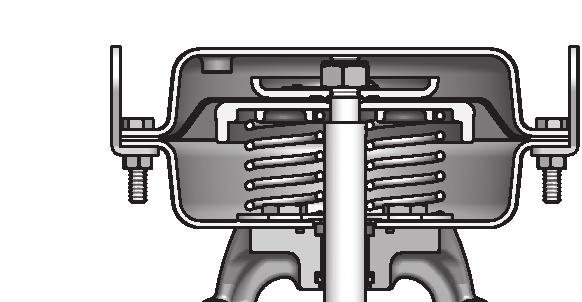
5 1. GENERAL This manual comprises a general overview of the structure, operating procedures, and maintenance of Model HIT Corrosion-Resistant Teflon Control Valves. 1.1 Structure A Corrosion-resistant Teflon Control valve consists of three major sections: valve body, actuator, and positioner as shown in Figure 1.1. Acturator Positioner Valve body Figure 1.1. Basic Structure of Control Valve 1

6 1.1.1 Valve Body There are two types of valve bodies: regular and bellows, classified by type of plug. The parts in contact with fluid, such as valve body interior, valve plug, and guides, are made of highly corrosion-resistant PTFE. The outer frame of valve body, the bonnet, and the valve stem are made of stainless steel Actuator The model HIT valve employs the Model PSK1 actuator, a multi-spring diaphragm motor. By its diaphragm and springs, it converts a pneumatic signal into a position signal with which to drive the valve plug via a valve stem. For manual operation, a manual handwheel can be installed on top of the control valve Positioner (optional) Refer to the relevant operator's manual: OM : Single-acting Pneumatic Valve Positioner, Model VPE OM : Single-acting Electric/Pneumatic Valve Positioner, Model HEP CM1-AVP : Smart Valve Positioner, Model AVP 1.2 Control Valve Specifications A nameplate as shown in Figure 1.2, is attached to each control valve. The nameplate indicates the model number, product number, date of manufacture, valve size, parts materials, and other major specifications. Before using the control valve, be sure its specifications conform with your intended use. When making any inquires on the control valve, such as for requesting information on modifications of the valve or ordering replacement parts, please mention the product number. Figure 1.2. Control Valve Nameplate 2
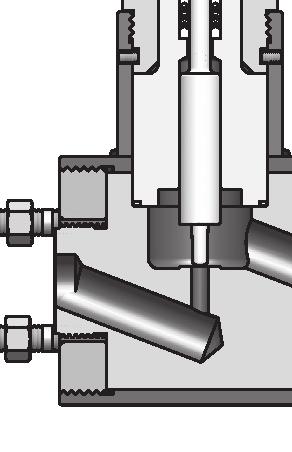
7 2. STRUCTURE 2.1 Structure of Valve Body Regular The structure of the regular valve body is shown in Figure No. Parts Material No. Parts Material 1 Valve stem SUS Bonnet SUS304 2 O-ring(P10) FEPM 13 Guide holder PTFE 3-1 Packing compression nut SUS Screw(M6x10L) SUSXM7 3-2 Lock nut SUS Valve plug PTFE 4 O-ring(P16) FEPM 16 Valve body SUS304 5 Spring SUS Rubber seat FPM 6 Packing ring SUS O-ring FEPM 7 V PTFE retainer PTFE 18-2 PTFE ring PTFE 8 V PTFE packing PTFE 18-3 O-ring FEPM 9 V PTFE receiver PTFE 19 Flow direction indicator SUS Retainer SUS Driving screw SUS Screw SUS PTFE main body PTFE Figure 2.1. Structure of the Regular Valve 3
8 2.1.2 Bellows Type Structure of the bellows-type valve body is shown in Figure No. Parts Material No. Parts Material 1 Valve stem SUS Bonnet SUS Packing compression nut SUS Tape liner PTFE(V-7980) 2-2 Lock nut SUS Screw(M6x10L) SUSXM7 3 O-ring(P10) FEPM 18-1 O-ring FEPM 4 O-ring(P16) FEPM 18-2 PTFE ring PTFE (For upper guide spacer) 5 V PTFE retainer PTFE 18-3 O-ring FEPM 6 V PTFE packing PTFE 19 Guide spacer PTFE 7 V PTFE receiver PTFE 20 Valve plug PTFE 8 Spring SUS Rubber seat FPM 9 Packing ring SUS O-ring FEPM 10 Vent plug SUS PTFE ring PTFE (For lower guide spacer) 11 Vent bushing SUS O-ring FEPM 12 Valve body SUS Flow direction indicator SUS Retainer SUS Driving screw SUS PTFE main body PTFE Figure 2.2. Structure of Bellows-type Valve 4
9
10
11
12
13
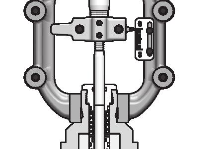
14 3 5 6 Pneumatic actuator Valve body No. parts 1 Stem connector (pointer) 2 Bolt 3 Actuator stem 4 Valve stem 5 Yoke 6 Setscrew (hex socket head) Figure 6.1. Parts for Removing the Actuator 6.3 Disassembly of Valve Body Disassembly of Regular Valve Body For disassembly of the regular valve body, refer to Figure 2.1 and proceed as follows: (1) Loosen the packing compression nut -1. (2) Loosen the four hex-socket-head setscrews (M6) around the bonnet by using a hex bar wrench (nominal size 3 mm). Loosen the bonnet from the valve body by using a wrench (nominal size 65 mm). Pull up the bonnet to remove it from the valve stem. (3) Remove the guide holder. Remove the valve stem together with the valve plug. CAUTION Never remove the seal retainer, PTFE main body, or rubber seat from the valve body. (4) Remove the packing compression nut -1, spring, packing ring, V PTFE retainer, V PTFE packing and V PTFE receiver from the bonnet and guide holder. (5) Remove the gland. O-ring and guide O-ring. 10
15 6.3.2 Disassembly of Bellows-type Valve Body For disassembly of the bellows-type valve body, refer to Figure 2.2 and proceed as follows: (1) Loosen the packing compression nut -1. (2) Loosen the four hex-socket-head setscrews (M6) around the bonnet by using a hex bar wrench (nominal size 3 mm). Loosen the bonnet from the valve body by using a wrench (nominal size 65 mm). Pull up the bonnet to remove it from the valve stem. (3) Remove the valve stem together with the valve plug. Remove the guide spacer. CAUTION Never remove the seal retainer, PTFE main body, or rubber seat from the valve body. (4) Remove the packing compression nut -1, spring, packing ring, VPTFE retainer, V PTFE packing and V PTFE receiver from the bonnet. (5) Remove the gland. O-ring and guide O-ring. 6.4 Disassembly of Actuator Disassembly of Direct-acting Actuator For disassembly of the direct-acting actuator, refer to Figure 6.2 and proceed as follows: (1) Disconnect the air piping and accessories from the actuator. (2) Remove the stem connector. (3) Remove the bolts (except the eyebolts) of the diaphragm case. (4) Loosen the nuts of the two eyebolts gradually and evenly. [These two bolts determine the initial spring compression setting when assembling the actuator.] (5) Remove the diaphragm case. Remove the rod and diaphragm unit upwards. (6) Remove the springs Disassembly of Reverse-action Actuator For disassembly of the reverse-acting actuator, refer to Figure 6.3 and proceed as follows: (1) Disconnect the air piping and accessories from the actuator. (2) Remove the stem connector. (3) Remove the bolts (except the eyebolts) of the diaphragm case. (4) Loosen the nuts of the two eyebolts gradually and evenly. [These two bolts determine the initial setting of spring compression when assembling the actuator.] (5) Remove the diaphragm case. Take out the springs. (6) Remove the rod and diaphragm unit upwards. 11
16
17 7. ASSEMBLY OF CONTROL VALVE CAUTIONS Before starting assembly, fully inspect all parts. If you find any damaged parts, replace them with new ones. Never re-use old gland packing. Be sure to use fresh gland packing whenever assembling the control valve. When ordering parts, please also mention the product number of the control valve, which is indicated on the nameplate. 7.1 Assembly of Valve Body For assembly of the valve body, as a general rule, follow the disassembly procedures in the reverse order. Thoroughly clean all parts before starting assembly. Be sure they do not carry dust, dirt or other foreign matter. All sealing parts and mating surfaces should be covered with grease or another appropriate sealing lubricant that will not be attacked by the process fluid. When control valves are shipped from the factory, silicone grease is applied as sealing lubricant (except for oil-free control valves.) Assembly of Regular Valve Body For assembly of the regular-type valve body, refer to Figure 2.1 and proceed as follows: (1) Set the O-ring -1, 3 and PTFE ring -2 in the valve body. (2) Set the valve plug with valve stem in the guide holder, and set them in the valve body. (3) Setting so that the valve stem passes through the center of the bonnet, couple the bonnet to the valve body using the threads. Turn the bonnet with the specified torque until the threading shoulder of the bonnet is brought into contact with the top plane of the valve body cylinder. For the tightening torque of the bonnet, see Table 7.1. (4) Apply Loctite to the four M6 hex-socket-head screws and drive them into the bonnet so that the bonnet is securely fixed and does not become loose. (When the valves are shipped from the factory, Loctite #602 is applied as the locking agent.) For the tightening torque of the setscrews, see Table 7.1. (5) Set the gland parts,,,,, and in this order. (6) Tighten the packing compression nut -1 until it is brought into contact with the bonnet. For the tightening torque of the nut, see Table Assembly of Bellows-type Valve Body For assembly of the bellows-type valve body, refer to Figure 2.2 and proceed as follows: (1) Set the O-ring -1, 3 and PTFE ring -2 in the valve body. (2) Set the guide spacer in the valve body. 13
18 (3) Set the O-ring -1, 3 and PTFE ring -2 in the guide spacer. Set the valve plug with valve stem into a position that the brim section of the valve plug is aligned with the centering location of the guide spacer. (4) Apply the tape liner on the bore of the bonnet. (The tape liner acts as a guide for the valve stem.) (5) Setting so that the valve stem passes through the center of the bonnet, couple the bonnet to the valve body by means of the threads. Turn the bonnet with the specified torque until the threading shoulder of the bonnet is brought into contact with the top plane of the valve body cylinder. For the tightening torque of the bonnet, see Table 7.1. (6) Apply Loctite to the four M6 hex-socket-head screws and drive them into the bonnet so that the bonnet is securely fixed and does not become loose. (When the valves are shipped from the factory, Loctite #602 is applied as the locking agent.) For the tightening torque of the setscrews, see Table 7.1. (7) Set the gland parts,,,,, and in this order. (8) Tighten the packing compression nut -1 until it is brought into contact with the bonnet. For the tightening torque of the nut, see Table 7.1. Table 7.1. Tightening Torques (N m {kgf cm}) Valve Size Bonnet Hex-socket-head Setscrews Packing Compression Nut 3/4" & 1" 250 ± 37 {2500 ± 375} [M68 1.5] 300 ± 45 {3000 ± 450} [M90 2] 350 ± 51 {3500 ± 525} [M ] 1-1/2" 8 ± 1.2 {80 ± 12} [M6 screw] 80 ± 12 {800 ± 120} [M26 1.5] 2" 7.2 Assembly of Actuator Before starting assembly, be sure the parts are perfect without any flaws, deformation, peeling of paint, or other defects, To assemble the actuator, proceed as follows: Assembly of Direct-acting Actuator To assembly the direct-acting actuator, proceed as follows: (l) Set the bearing (together with the dust seal) to the yoke. Fix the bottom diaphragm case to the yoke with the four M10 bolts. (2) Fix the spring plate (sec Figure 7.1) and set the springs on the spring plate. (3) Insert in to the bearing the rod to which the diaphragm has been set. When doing this, be careful not to damage the bearing and dust seal with the threaded section of the rod. (For example, cover the threaded section with adhesive vinyl tape.) 14
19
20
21
22
23 235 ø218 (28) H A Figure 7.4. Overall Dimensions Table 7.3. Overall Dimensions and Weights Valve size (inch) 3/ /2 2 A (mm) H (mm) PSK1D PSK1R Weight (kg)
24 8. DIRECT/REVERSE-ACTING CONVERSION AND SPRING RANGE MODIFICATION 8.1 Conversion To Direct- or Reverse-acting Type When you want to convert your control valve into a reverse-action type or a direct-action type, it is recommended to change the whole actuators. However, if you want to convert your actuator by replacing required parts only, you need the parts shown in Table 8.1 or 8.2. In these tables, + denotes the new parts which you need to acquire for the conversion and - denotes the parts which you don't need for the conversion and which will become surplus parts. Table 8.1. Parts for Direct to Reverse Conversion PSK1D PSK1R Parts Q'ty Parts No. Seal washers Rod packing Rain cap Table 8.2. Parts for Reverse to Direct Conversion PSK1R PSK1D Parts Q'ty Parts No. Seal washers Rod packing Rain cap For the conversion procedure, refer to Chapter 6 DISASSEMBLY OF CONTROL VALVE and Chapter 7 ASSEMBLY OF CONTROL VALVE. 8.2 Spring Range Modification To change spring ranges of Model PSK1 Actuator, refer to Table 8.3 which indicates the color coding, dimensions and the required quantities of actuator springs. Table 8.3. Actuator Springs Spring range kpa {kgf/cm 2 } Color coding Free length of springs mm Q'ty { } { } Yellow 89 4 Orange
25
26
27
28 10. OVERALL DIMENSIONS AND WEIGHTS (1) Main Unit of Model PSK1 235 ø M9 1 ø34.9 Stroke: 20 mm Effective diaphragm area: 160 cm 2 Maximum capacity of diaphragm chamber: 700 cm 2 Weight: 8 kg Table Overall Dimensions (Main Unit) (2) Actuator with Top Handwheel Stroke mm Overall dimensions mm øb B ød H Maximum handwheel operating force N {kgf} Weight (kg) {16} 9.5 Table Overall Dimensions (Actuator with Handwheel) 24
29
30
31 Document Number: Document Name: OM Corrosion-Resistant Teflon Control Valve Model : HIT User's Manual Date: 1st edition: Nov nd edition: Dec Issued/Edited by: Azbil Corporation
32
CV3000 Series Control Valves Model: AMT. User s Manual
 CM2-AMT100-2001 CV3000 Series Control Valves Model: AMT User s Manual AMT000001000P Copyright, Notices and Trademarks While this information is presented in good faith and believed to be accurate, Azbil
OM Weir-Type Diaphragm Control Valve Model : VDD User s Manual
 OM2-8110-0530 Weir-Type Diaphragm Control Valve Model : VDD User s Manual Copyright, Notices and Trademarks 1988-2013 Azbil Corporation. All Rights Reserved. While this information is presented in good
User s Manual CM2-ALV nd edition
 Control Valve Model: ALVB, ALVM ANSI Class 300 or under User s Manual CM2-ALV100-2001 2nd edition Copyright, Notices and Trademarks 2007-2012 Azbil Corporation All Rights Reserved. While this information
DAP Springless Piston Cylinder
 CM2-DAP100-2001 DAP Springless Piston Cylinder User's Manual NOTICE While the information in this manual is presented in good faith and believed to be accurate, Azbil Corporation disclaims any implied
Ceramic Control Valves Model : HIC User's Manual OM
 Ceramic Control Valves Model : HIC User's Manual OM2-8193-0300 Copyright, Notices and Trademarks 2013 Azbil Corporation. All Rights Reserved. While this information is presented in good faith and believed
CV3000 Series Control Valves Model: HCB,HCU,HCN,HPC
 OM2-8113-0202 CV3000 Series Control Valves Model: HCB,HCU,HCN,HPC User's Manual NOTICE While this information is presented in good faith and believed to be accurate, Azbil Corporation disclaims the implied
User s Manual OM th edition
 FloWing Eccentric Rotary type Control Valves Model: VFR (1, 1½, 2 inches) User s Manual OM2-8130-0300 5th edition Copyright, Notices and Trademarks 2012 Azbil Corporation All Rights Reserved. While this
CV3000 Series Control Valve Model : HLS,HTS,HPS,HLC,HSC,HAV
 OM2-8113-0201 CV3000 Series Control Valve Model : HLS,HTS,HPS,HLC,HSC,HAV User's Manual NOTICE While this information is presented in good faith and believed to be accurate,azbil Corporation disclaims
Model HIT. Corrosion-Resistant PTFE Body Control Valves OVERVIEW SPECIFICATIONS. No. SS
 No. SS2-8193-0200 Corrosion-Resistant Body Control Valves Model HIT OVERVIEW The Corrosion Resistant Body Control Valves (model HIT) are best suited for handling corrosive fluids such as acids and alkali
FloWing Eccentric Rotary type Control Valves. Model: VFR (6-inch or more) User s Manual
 User s Manual") FloWing Eccentric Rotary type Control Valves Model: VFR (6-inch or more) User s Manual OM2-8130-0200 6th edition Copyright, Notices and Trademarks 2012 Azbil Corporation All Rights Reserved. While this
FloWing Eccentric Rotary type Control Valves Model: VFR (6-inch or more) User s Manual OM2-8130-0200 6th edition Copyright, Notices and Trademarks 2012 Azbil Corporation All Rights Reserved. While this
OM Micro-Flow Control Valve Model: VSM. User s Manual
 OM2-8110-0500 Micro-Flow Control Valve Model: VSM User s Manual NOTICE While this information is presented in good faith and believed to be accurate, Azbil Corporation disclaims the implied warranties
Pneumatically-Operated, Single-Seated Control Valve
 No. SS-ACT100-0100 OVERVIEW The NEW10-III is a compact, lightweight, and economical simple-function control valve designed for JIS10K process line. It is highly reliable and best suited for process con
OM Micro-Flow Control Valve Model: VSM. User s Manual
 OM2-8110-0500 Micro-Flow Control Valve Model: VSM User s Manual NOTICE While this information is presented in good faith and believed to be acdurate, Azbil Corporation disclaims the implied warranties
Mounting and operating instructions EB 8093 EN. Series 240 Pneumatic Control Valve for Cryogenic Temperatures. Type and
 Series 240 Pneumatic Control Valve for Cryogenic Temperatures Type 3248-1 and 3248-7 Fig. 1 Type 3248 Cryogenic Valve with Type 3277 Pneumatic Actuator as globe and angle valve Mounting and operating instructions
OM Field-Type I/P Converter Model : KUX113 User's Manual
 OM2-5900-1130 Field-Type I/P Converter Model : KUX113 User's Manual Copyright, Notices and Trademarks 1994-2012 Azbil Corporation All Rights Reserved. While this information is presented in good faith
Serie 2003/2013. Three-way Control Valve, mixing/diverting. Wörth am Main. Service. Control Valve Division
 Serie 2003/2013 Three-way Control Valve, mixing/diverting Service Preventive maintenance Preventive maintenance primarily consists of making a regular visual inspection of the valve assembly. This can
CV3000 Alphaplus Series Electric Top-Guided Single-Seated Control Valves Model: AGVB / AGVM. User s Manual
 CV3000 Alphaplus Series Electric Top-Guided Single-Seated Control Valves Model: AGVB / AGVM User s Manual CM2-AGV300-2001 Copyright, Notices and Trademarks While this information is presented in good faith
Series 250 Pneumatic Control Valves Type and
 Series 250 Pneumatic Control Valves Type 3252-1 and 3252-7 Fig. 1 Type 3252 High-pressure Valve with Type 3277 Pneumatic Actuator and Type 3767 i/p Positioner Edition November 1998 Mounting and operating
NEW10-III Pneumatic Single-Seated Control Valve Model: ACT. User s Manual
 NEW10-III Pneumatic Single-Seated Control Valve Model: ACT User s Manual CM2-ACT100-2001 1st edition: May. 2003, 3rd editon: Nov. 2014 Copyright, Notices and Trademarks Copyright 2003-2014 Azbil Corporation
Series Single seated top guided control valve. Preventive maintenance. Overhauling procedure. Wörth am Main SERVICE NOTE. Control Valve Division
 Series 2000 Single seated top guided control valve Subject to change without notice Fig. 1: Series 2000 valve assembly Preventive maintenance Preventive maintenance consists of making a periodic visual
Series 240 Type and Type Pneumatic Control Valves Type 3248 Cryogenic Valve
 Series 240 Type 3248-1 and Type 3248-7 Pneumatic Control Valves Type 3248 Cryogenic Valve ANSI version Application Globe or angle valve for cryogenic applications Easy to service due to top-entry design
Series 9000 Control Valves RESEARCH Control Valves
 Model 900 Series 9000 Control Valves RESEARCH Control Valves Instruction Manual INSTALLATION Inspect unit for shipment damage. Remove protective plugs from body and air signal connection. NOTE: Leave vent
Mounting and Operating Instructions EB 5868/5869 EN
 Electric Control Valves Types 3213/5857, 3213/5824, Types 3214/5824, 3214/3374, 3214/3274 with safety function: Types 3213/5825, 3214/5825, 3214/3374, 3214/3274 Pneumatic Control Valves Types 3213/2780-1,
Globe Control Valve Series 1a
 Maintenance Globe Control Valve Series 1a are subject to alteration without notice. The text and illustrations do not necessarily display the scope of supply or any ordering of spare parts. Drawings and
Series 240 Type and Type Pneumatic Control Valves Type 3248 Cryogenic Valve
 Series 240 Type 3248-1 and Type 3248-7 Pneumatic Control Valves Type 3248 Cryogenic Valve ANSI version Application Globe or angle valve for cryogenic applications Easy to service due to top-entry design
CV Control Valves Installation and Operation Manual
 CV1500 - Control Valves Installation and Operation Manual 652-EN Overview Warning: This bulletin should be used by experienced personnel as a guide to the installation of the Armstrong CV1500 Control Valve.
FIGURE 310A & 311A 3-PIECE BALL VALVE
 INTRODUCTION This instruction manual includes installation, operation and maintenance information for the figure 310A, 310ASW, 311A, and 311ASW 3-piece 1000CWP, threaded end (NPT) or socket weld end (SW)
Mounting and Operating Instructions EB 8039 EN. Type 3351 Pneumatic On/off Valve. Type 3351 Pneumatic On/off Valve. Type 3351 Pneumatic On/off Valve
 Type 3351 Pneumatic On/off Valve Type 3351 Pneumatic On/off Valve Type 3351 Pneumatic On/off Valve Version with handwheel Mounting and Operating Instructions EB 8039 EN Edition May 2016 Definition of signal
Mounting and Operating Instructions EB 8053 EN. Series 250 Type and Type Pneumatic Control Valves
 Series 250 Type 3252 1 and Type 3252 7 Pneumatic Control Valves Type 3252 High-pressure valve with Type 3277 Pneumatic Actuator and Type 3767 Electropneumatic Positioner Mounting and Operating Instructions
Valtek Auxiliary Handwheels and Limit Stops
 Valtek Auxiliary s and Limit Stops Table of Contents Page 1 General information 2 Installation 2 Side-mounted handwheels, size 25 and 50 (linear actuators) 3 Side-mounted handwheels, size 100 and 200 (linear
Mounting and operating instructions EB Pneumatic Control Valve Type and Type Globe Valve Type 3522 ANSI Class 300
 Pneumatic Control Valve Type 3522-1 and Type 3522-7 Globe Valve Type 3522 ANSI Class 300 Fig. 1 Type 3522-7 Control Valve with integrated positioner Mounting and operating instructions EB 8822 Edition
Fisher 3024C Diaphragm Actuator
 Instruction Manual 3024C Actuator Fisher 3024C Diaphragm Actuator Contents Introduction... 1 Scope of Manual... 1 Description... 2 Specifications... 3 Installation... 5 Mounting the Actuator on the Valve...
Fisher 657 Diaphragm Actuator Sizes and 87
 Instruction Manual 657 Actuator (30-70 and 87) Fisher 657 Diaphragm Actuator Sizes 30 70 and 87 Contents Introduction... 1 Scope of Manual... 1 Description... 2 Specifications... 2 Installation... 3 Mounting
Standard Valves Series Globe Valves Series Angle Valves Series Way-Valves
 Installation, Operation, Maintenance Instructions Standard Valves Series 035 000 Globe Valves Series 031 000 Angle Valves Series 033 000 3-Way-Valves 1 GENERAL INFORMATION These instructions are designed
J Flow Controls Model Numbering
 4665 Interstate Dr Cincinnati, OH 45246 Phone 513-731-2900 Fax 513-731-6939 3500 Series Valve Instruction and Maintenance Manual Caution: Prior to performing any repairs or maintenance on the valve assembly,
FIGURE 310AM, 310AMSW & 311AM 3-PIECE BALL VALVE
 INTRODUCTION This instruction manual includes installation, operation and maintenance information for the figure 310AM, 310AMSW, and 311AM 3-piece 1000CWP, threaded end (NPT) or socket weld end (SW) ball
INSTALLATION & MAINTENANCE MANUAL
 INSTALLATION & MAINTENANCE MANUAL 3-WAY/4-WAY/5-WAY MULTI-PORT BALL VALVES T TEFLON PARTS - 1. Seat x 5 pcs. 2. Joint Gasket x 5 pcs. 3. Retainer Seal x 5 pcs. 4. Thrust Washer x 1 pc. 5. O-Ring x 1 pc
Baumann Pneumatic Actuators
 Instruction Manual Baumann Pneumatic Actuators Baumann Pneumatic Actuators Contents Introduction... 1 Scope of Manual... 1 Design Notes... 2 Installation... 2 Attaching an Air-to-Retract (ATR) Actuator
Design GX Control Valve and Actuator System
 Instruction Manual GX Valve and Actuator Design GX Control Valve and Actuator System Contents Introduction............................... 1 Scope of Manual......................... 1 Description..............................
Operating & Maintenance Manual For Steam Conditioning Valve
 For Steam Conditioning Valve 1 Table of Contents 1.0 Introduction 3 2.0 Product description 3 3.0 Safety Instruction 4 4.0 Installation and Commissioning 5 5.0 Valve Disassembly 6 6.0 Maintenance 6 7.0
Mounting and Operating Instructions EB 8091 EN. Pneumatic Control Valve Type and Type Type with 120 cm 2 actuator
 Pneumatic Control Valve Type 3510-1 and Type 3510-7 Type 3510-1 with 120 cm 2 actuator Type 3510-7 with 120 cm 2 actuator and integrated positioner Type 3510-1 with 60 cm 2 actuator Fig. 1 Pneumatic control
Globe Valve Type Fig. 1 Type 3241 Globe Valve. Mounting and Operating Instructions EB EN
 Globe Valve Type 3241 Fig. 1 Type 3241 Globe Valve Mounting and Operating Instructions EB 8015-1 EN Edition July 2012 Contents Contents Page 1 Design and principle of operation.................... 4 2
Butterfly Valve Type 57P
 Butterfly Valve Type 57P Contents Lever Type: 50-200 mm (2-8 ) Body Material: CPVC Gear Type: 50-200mm (2-8 ) Body Material: CPVC (1) Be sure to read the following warranty clauses of our product 1 (2)
Rev. E Sept 06. VP300 INSTRUCTION MANUAL Part # DISPENSING VALVE MODEL VP300 INSTRUCTION MANUAL
 DISPENSING VALVE MODEL VP300 INSTRUCTION MANUAL CONTENTS 1 Introduction page 3 2 Specifications page 3 3 Part Description page 4 4 Operating Principles page 5 5 Operating Procedure 5-1 Setup page 6 5-2
Baumann 24000F Wafer Control Valve
 Instruction Manual 24000F Valves Baumann 24000F Wafer Control Valve Contents Introduction... 1 Scope of Manual... 1 Safety Precautions... 2 Maintenance... 2 Installation... 3 Air Piping... 3 Disassembly...
Model DF269 Control Valve
 Figure 1 DF269 Control Valve TABLE OF CONTENTS Introduction 2 Fail Open Actuator Disassembly 6 General 2 Body and Packing Reassembly 7 Scope 2 Fail Closed Actuator Resassembly 8 Specifications 3 Fail Open
Top-Guided Single Seated Control Valves (Rating : ANSI 600 or Less)
") No. SS2-8-0 Top-Guided Single Seated Control Valves (Rating : ANSI 0 or Less) OVERVIEW Model VST control valves are suitable for use in fluid with slurry because of its one side guiding construction. Guide
No. SS2-8-0 Top-Guided Single Seated Control Valves (Rating : ANSI 0 or Less) OVERVIEW Model VST control valves are suitable for use in fluid with slurry because of its one side guiding construction. Guide
I & M 8000 Series. Ideal Installation Schematic. Preferred Installation. Trouble Shooting
 I & M 8000 Series 3170 Wasson Road Cincinnati, OH 45209 USA Phone 513-533-5600 Fax 513-871-0105 lowflow@richardsind.com www.lowflowvalve.com Installation & Maintenance Instructions for 8000 Series Low
Mounting and Operating Instructions EB 8048 EN. Type and Type Pneumatic Control Valves Type 3249 Aseptic Angle Valve
 Type 3249-1 and Type 3249-7 Pneumatic Control Valves Type 3249 Aseptic Angle Valve Ball body version Special version with packing Type 3249-7 Control Valve with Type 3277 Actuator and integrated positioner
Baumann Way Control Valve
 Instruction Manual 24003 Valve Baumann 24003 3-Way Control Valve Contents Introduction... 1 Scope of Manual... 1 Safety Precautions... 2 Educational Services... 3 Maintenance... 3 Installation... 3 Air
Mounting and Operating Instructions EB 8097 EN. Type and Type Pneumatic Control Valves
 Type 3347-1 and Type 3347-7 Pneumatic Control Valves Type 3347-7, cast body with welding ends Type 3347-7, bar stock body with threaded connections Mounting and Operating Instructions EB 8097 EN Edition
Mounting and Operating Instructions EB 8097 EN. Pneumatic Control Valves Type and Type
 Pneumatic Control Valves Type 3347-1 and Type 3347-7 Hollow-mold cast body with welding ends Full-mold cast body with threaded connections Fig. 1 Type 3347-7 Control Valve with Type 3277 Actuator and integral
Fisher GX Control Valve and Actuator System
 Instruction Manual D103175X012 GX Valve and Actuator Fisher GX Control Valve and Actuator System Contents Introduction............................... 1 Scope of Manual.......................... 1 Description...............................
Baumann Little Scotty Bronze Control Valve
 Instruction Manual 24000 Valve Baumann 24000 Little Scotty Bronze Control Valve Contents Introduction... 1 Scope of Manual... 1 Safety Precautions... 2 Maintenance... 2 Installation... 3 Air Piping...
Butterfly Valve Type 58 (PDCPD)
") Serial No. H-V074-E Butterfly Valve Type 58 (PDCPD) 700mm (28 ) User s Manual Contents (1) Be sure to read the following warranty clauses of our product 1 (2) General operating instructions 2 (3) General
Serial No. H-V074-E Butterfly Valve Type 58 (PDCPD) 700mm (28 ) User s Manual Contents (1) Be sure to read the following warranty clauses of our product 1 (2) General operating instructions 2 (3) General
Model DF233 Control Valve
 Figure 1 DF233 Control Valve TABLE OF CONTENTS Introduction 2 Body and Packing Reassembly 7 Specifications 3 Fail Closed Actuator Reassembly 8 Valve Sizes 3 Fail Open Actuator Reassembly 9 Unpacking 4
Fisher GX Control Valve and Actuator System
 Instruction Manual GX Valve and Actuator Fisher GX Control Valve and Actuator System Contents Introduction... 1 Scope of Manual... 1 Description... 1 Specifications... 2 Educational Services... 2 Valve
CONTROL VALVE
 CONTROL VALVE 30 000 GENERALS The valves serial "30 000" are designed for a range of general-purpose pneumatic controlled valves. Their application extends over the most various industrial branches: food,
Model DFR 070/156/220 Rotary Actuator
 Figure 1 DFR 156 TABLE OF CONTENTS General 2 Actuator Assembly 18 Scope 2 Bushing / Yoke Assembly 18 Principles of Operation 2 Spring Barrel Assembly 18 Safety Caution 2 Diaphragm Plate Assembly 20 Specifications
Model DFR 026 Rotary Actuator
 Figure DFR 026 and 57 Control Valve TABLE OF CONTENTS General 2 Actuator Assembly 4 Scope 2 Bushing Installation 4 Principles of Operation 2 Mounting Yoke / Hub Assembly 4 Safety Caution 2 Spring / Adjuster
ANDERSON GREENWOOD. Before installation these instructions must be fully read and understood.
 ANDERSON GREENWOOD Before installation these instructions must be fully read and understood. 1.1 General The Anderson Greenwood Series 200 Pilot Operated SRV uses the principle of pressurizing the larger
CV3000 Alphaplus series Top and Bottom Guided Double-Seat Control Valves (6 to 12inches)
") No. SS2-ADV100-0100 CV3000 Alphaplus series Top and Bottom Guided Double-Seat Control Valves (6 to 12inches) OVERVIEW Model ADVB / ADVM The CV3000 Alphaplus top and bottom guided double-seat control valves
No. SS2-ADV100-0100 CV3000 Alphaplus series Top and Bottom Guided Double-Seat Control Valves (6 to 12inches) OVERVIEW Model ADVB / ADVM The CV3000 Alphaplus top and bottom guided double-seat control valves
Spring-Engaged/Hydraulically-Released BD Caliper Brake. (i) MTY (81) QRO (442) MEX (55)
 MTY (81) QRO (442) MEX (55)") Spring-Engaged/Hydraulically-Released BD Caliper Brake (i) FORM NO. L-07-E-0300 In accordance with Nexen s established policy of constant product improvement, the specifications contained in this manual
Spring-Engaged/Hydraulically-Released BD Caliper Brake (i) FORM NO. L-07-E-0300 In accordance with Nexen s established policy of constant product improvement, the specifications contained in this manual
PN9000 Series Pneumatic Actuators Installation and Maintenance Instructions
 3579049/14 IM-P357-29 CTLS Issue 14 PN9000 Series Pneumatic Actuators Installation and Maintenance Instructions PN9100 PN9200 1. Safety information 2. General product information PN9300 3. Installation
I & M Mark 78 Series. Ideal Installation. Start-Up. Installation & Maintenance Instructions for Mark 78 Control Valves (1-1/2-2 )
") I & M Mark 8 Series 0 Wasson Road Cincinnati, OH 4509 USA Phone 5-5-5600 Fax 5-8-005 info@richardsind.com www.jordanvalve.com Installation & Maintenance Instructions for Mark 8 Control Valves (-/ - ) Warning:
I & M Mark 8 Series 0 Wasson Road Cincinnati, OH 4509 USA Phone 5-5-5600 Fax 5-8-005 info@richardsind.com www.jordanvalve.com Installation & Maintenance Instructions for Mark 8 Control Valves (-/ - ) Warning:
BR 01b Control valve
 Maintenance Instructions BR 01b Control valve 1. General These instructions are intended to assist the user on assembling and repairing BR 01b Control Valves. Technical specifications, as a result of further
T 8053 EN Type and Type Pneumatic Control Valves Type 3252 High-pressure Valve
 T 8053 EN Type 3252-1 and Type 3252-7 Pneumatic Control Valves Type 3252 High-pressure Valve Application Control valve especially designed for controlling low flow rates in process engineering Valve sizes
Swing Check Valve ASAHI AV VALVES. Contents. User s Manual. (1) Be sure to read the following warranty clauses of our product 1
 Be sure to read the following warranty clauses of our product 1") Serial No. H-V013-E-13 Swing Check Valve User s Manual Contents (1) Be sure to read the following warranty clauses of our product 1 (2) General operating instructions 2 (3) General instructions for transportation,
Serial No. H-V013-E-13 Swing Check Valve User s Manual Contents (1) Be sure to read the following warranty clauses of our product 1 (2) General operating instructions 2 (3) General instructions for transportation,
Series 1b Control Valve
 Maintenance Instructions Series 1b Control Valve 1. General These instructions are intended to assist the user on assembling and repairing Series 1b Control Valves. Technical specifications, as a result
Baumann Series Flexsleev Control Valve Instructions
 Instruction Baumann 86000 Series Instructions Baumann 86000 Series Flexsleev Control Valve Instructions Contents Introduction...1 Scope...1 Safety Precautions...1 Maintenance...2 Installation...3 Air Piping...3
Pfeiffer. Maintenance instructions 3-way control valve Series 1d. 2. Design, operation and dimensions. 3. Installation, start-up and maintenance
 Maintenance instructions 3-way control valve Series 1d This equipment may only be dismounted and disassembled by skilled staff, who are familiar with the assembly, start-up, and operation of this product.
Installation,Operation and Maintenance Manual H-V016-E-10. Serial No. 目次 ( ページ ) 1. Be sure to read the following warranty clauses of our product 1
 1. Be sure to read the following warranty clauses of our product 1") Serial No. H-V016-E-10 Gauge Valve 目次 ( ページ ) 1. Be sure to read the following warranty clauses of our product 1 2. General operating instructions 2 User s Manual 3. General instructions for transportation,
Serial No. H-V016-E-10 Gauge Valve 目次 ( ページ ) 1. Be sure to read the following warranty clauses of our product 1 2. General operating instructions 2 User s Manual 3. General instructions for transportation,
Baumann 24000CVF Carbon & 24000SVF Stainless Steel Flanged Valve Instructions
 Instruction Manual D103360X012 24000CVF/SVF Control Valve Baumann 24000CVF Carbon & 24000SVF Stainless Steel Flanged Valve Instructions CONTENTS Introduction...1 Scope of Manual...1 Safety Precautions...1-2
Fisher 667NS2 Diaphragm Actuator Size 45, 70, and 80
 Instruction Manual 667NS Actuator Fisher 667NS Diaphragm Actuator Size 5, 70, and 80 Contents Introduction... 1 Scope of Manual... 1 Description... Specifications... 3 Educational Services... 3 Maximum
Sub Section Title Page No.
 Sub Section Title Page No. 1 Introduction 3 2 Routine Maintenance 3 3 Disassembly 4 3.1 Disassembly of Double Crank Design 4 3.2 Disassembly of Scotch Yoke Design 5 3.3 Disassembly of Actuator Cylinder
Baumann 24000C Carbon Steel Little Scotty Control Valve Instructions
 Instruction Manual D103356X012 24000C Control Valve Baumann 24000C Carbon Steel Little Scotty Control Valve Instructions CONTENTS Introduction...1 Scope...1 Safety Precautions...1 Maintenance...2 Flow
CONTROL VALVES. Installation, Maintenance & Operating Instructions. Read these instructions carefully before installation or servicing.
 KOSO HAMMEL DAHL CONTROL VALVES KOSO HAMMEL DAHL 253 Pleasant Street West Bridgewater, MA 02379 tel: 774.517.5300 fax: 774.517.5230 www.hammeldahl.com Installation, Maintenance & Operating Instructions
Fisher 1051 and 1052 Style H and J Sizes 40, 60 and 70 Rotary Actuators
 Instruction Manual 1051 and 1052 H & J Actuators Fisher 1051 and 1052 Style H and J Sizes 40, 60 and 70 Rotary Actuators Contents Introduction... 1 Scope of Manual... 1 Description... 2 Specifications...
Pressure Reducing Valve Type 2114/2415
 Pressure Reducing Valve Type 2114/2415 Fig. 1 Type 2114/2415 1. Design and principle of operation The Type 2114/2415 Pressure Reducing Valve consists of the Type 2114 Valve and the Type 2415 Actuator.
Split Body Valves with Bellows Seal Series Globe Valves Series Angle Valves Series Way-Valves
 Installation, Operation, Maintenance Instructions Split Body Valves with Bellows Seal Series 025 300 Globe Valves Series 027 300 Angle Valves Series 028 300 3-Way-Valves 1 GENERAL INFORMATION These instructions
Flowrite TM AP 599 Series 8-inch Pneumatic Valve Actuator
 Flowrite TM AP 599 Series 8-inch Pneumatic Valve Actuator Technical Instructions Document No. 155-161P25 AP 599-1 Description Features Application The Flowrite AP 599 Series 8-inch pneumatic valve actuator
Diaphragm Valve Type 72
 Serial No. H-V001-E-8 Diaphragm Valve Type 72 User s Manual Contents (1) Be sure to read the following warranty clauses of our product 1 (2) General operating instructions 2 (3) General instructions for
Flowrite AP 599 Series
 AP 599-2 Flowrite AP 599 Series 12-inch Pneumatic Valve Actuator Description The Flowrite AP 599 Series 12-inch pneumatic valve actuator is designed for use with the Flowrite VF 599 Series valves. This
Top-Guided Single-Seated Control Valves
 No. SS-AGV00-000 CV000 Alphaplus series Top-Guided Single-Seated Control Valves Model AGVB / AGVM OVERVIEW The CV 000 Alphaplus range of Top-guided Single-seat Control Valves features a compact valve body
HIGH PRESSURE CONTROL VALVE PISTON BALANCED
 PISTON BALANCED All Rights Reserved. All contents of this publication including illustrations are believed to be reliable. And while efforts have been made to ensure their accuracy, they are not to be
CV3000 Series Pressure-Balanced Cage type Control Valve
 No. SS2-ACP110-0100 OVERVIEW The model ACP pressure-balanced cage type control valves are designed for heavy duty service. The valve plug employs a pressure balance function to control high differential
Type 1051 and 1052 Size 33 Diaphragm Rotary Actuator
 Instruction Manual Type 1051 and 1052 Size 33 Diaphragm Rotary Actuator 1051 & 1052 Actuator Contents Introduction............................. 1 Scope of Manual........................... 1 Description................................
McCannalok HIGH PERFORMANCE BUTTERFLY VALVE OPERATION AND MAINTENANCE MANUAL. The High Performance Company
 McCannalok HIGH PERFORMANCE BUTTERFLY VALVE OPERATION AND MAINTENANCE MANUAL The High Performance Company Table of Contents Safety Information - Definition of Terms... 1 Introduction... 1 Installation...
I & M Mark 78 Series. Ideal Installation. Start-Up. Installation & Maintenance Instructions for Mark 78 Control Valves (1/2-1 )
") I & M Mark 8 Series 30 Wasson Road Cincinnati, OH 4509 USA Phone 53-533-5600 Fax 53-8-005 info@richardsind.com www.jordanvalve.com Installation & Maintenance Instructions for Mark 8 Control Valves (/ -
I & M Mark 8 Series 30 Wasson Road Cincinnati, OH 4509 USA Phone 53-533-5600 Fax 53-8-005 info@richardsind.com www.jordanvalve.com Installation & Maintenance Instructions for Mark 8 Control Valves (/ -
Diaphragm Valves Type 15
 Serial No. H-V031-E-8 Diaphragm Valves Type 15 User s Manual Contents (1) Be sure to read the following warranty clauses of our product 1 (2) General operating instructions 2 (3) General instructions for
TECHNICAL SERVICE MANUAL
 Electronic copies of the most current TSM issue can be found on the Viking Pump website at www.vikingpump.com TECHNICAL SERVICE MANUAL industrial heavy duty motor speed pumps SERIES 4076 AND 4176 SIZES
Easytork Vane Actuator IOM
 Easytork Vane Actuator IOM General Storage The Easytork Vane Actuator ( EVA ) is a high-quality product and as such must be handled, transported and stored with care. Prior to storage, inspect the actuator
Mounting and Operating Instructions EB 8135/8136 EN. Series V2001 Valves Type 3535 Three-way Valve for Heat Transfer Oil
 Series V2001 Valves Type 3535 Three-way Valve for Heat Transfer Oil Type 3535 Three-way Valve with bellows seal and rod-type yoke (partial view) Mounting and Operating Instructions EB 8135/8136 EN Edition
Nor East. Instructions Safety Messages. Inspection. Parts. DeZURIK Service. Type 05 Pneumatic Actuator Used With Globe Valves
 Instructions Safety Messages These instructions are intended for personnel who are responsible for installation, operation and maintenance of your DeZURIK Actuator. All safety messages in the instructions
Ceramic Trim Angle Control Valves
 No. SS2-8113-2610 Ceramic Trim Angle Control Valves Model HAF OVERVIEW Model HAF ceramic trim angle control valves provide the valve plug and sheet ring employing high performance ceramic with excellent
Gearbox Installation Manual
 Gearbox Installation Manual Rotork Gears IW, MOW, MTW, IB and IS ranges (Electronic copy available on www.rotork.com)! This manual contains important safety information. Please ensure it is thoroughly
SAMSON special tools. Fig. 1 Seat wrenches and supporting flanges WA 029 EN
 SAMSON special tools Fig. 1 Seat wrenches and supporting flanges WA 029 EN Edition November 2000 General information 1. General information Special seat tools are required to install or remove the seats
Eccentric Rotary Control Valve (For size 6 to 12 inches)
") No. SS2-VFR100-0100 OVERVIEW FloWing Eccentric Rotary Control Valve (For size 6 to 12 inches) Model VFR The eccentric rotary control valve, FloWing (model VFR), consists of a straight-through valve body
No. SS2-VFR100-0100 OVERVIEW FloWing Eccentric Rotary Control Valve (For size 6 to 12 inches) Model VFR The eccentric rotary control valve, FloWing (model VFR), consists of a straight-through valve body
4. Rear Axle REAR AXLE
 REAR AXLE DRIVE SHAFT SYSTEM 4. Rear Axle A: REMOVAL 1) Disconnect the ground cable from battery. 2) Lift-up the vehicle, and remove the rear wheel. 3) Unlock the axle nut. 4) Remove the axle nut using
MP and MP Diaphragm and Seal Kits for MP8000 Series Actuators
 MP8000-6325 and MP8000-6350 Diaphragm and Seal Kits for MP8000 Series Actuators Contents of the MP8000-6325 Diaphragm and Seal Kit for MP82 and MP83 Actuators One seal, 5/8 in. Internal Diameter (I.D.)