Series ULS Small Tank Ultrasonic Transmitter, Switch and Controller Series ULSS, ULSM, ULSL Manual
|
|
|
- Blake Baker
- 6 years ago
- Views:
Transcription


 USA www.")
1 L ULS Series ULS Small Tank Ultrasonic Transmitter, Switch and Controller Series ULSS, ULSM, ULSL Manual Dwyer Instruments Inc. 102 Indiana Hwy. 212 (P.O. Box 373) Michigan City, IN (46361) USA Inst.com Rev A MN of 30
2 INTRODUCTION / TABLE OF CONTENTS Step One Series ULS is an innovative level sensor family that replaces float, conductance and pressure sensors that fail due to contact with dirty, sticking and scaling media in small (< 4 /1.25m) to medium (<18 /5.5m) tall tanks. Applied in skid, machine, tool and process applications, the general purpose sensors are available with single and multi function capabilities including measurement, switching and control. Features Simple configuration with ULSX CAL software, no more target calibration Adjustable Loop Fail Safe Easy to reverse ma output Increased output filtering Table of Contents Specifications:... 3 Dimensions:... 4 Safety Precautions:... 5 Components:... 6 Getting Started:... 7 USB Fob Interface:... 7 ULSX CAL:... 8 Configuration:... 9 Tank Levels & Relay Values: Write to Unit & Wiring Diagram: Wiring: Wire Connections: Switch Inductive Loads: Installation: Mounting Guide: Fitting Selection: Tank Adapter: Riser: Flange: Side Mount Fitting: Stand Pipe: Advanced Feature: Appendix: Updating ULSX CAL Software: Updating Transmitter Firmware: Troubleshooting: Factory Defaults: Solution Table: Maintenance & Repair: of 30 MN Rev A
3 SPECIFICATIONS Range: Accuracy: Resolution: Dead band: Beam width: Configuration: Memory: Supply voltage: Consumption: Loop resistance: Signal output: Signal invert: Signal fail safe: Contact type: ULSS: 49.2 (1.25m) ULSM: 9.8 (3.0m) ULSL: 18.0 (5.5m) ULSS: (3mm) ULSM: +/ 0.2% of range ULSL: +/ 0.2% of range ULSS: (0.5mm) ULSM: (1mm) ULSL: (2mm) ULSS: 2 (5 cm) ULSM: 4 (10 cm) ULSL: 8 (20 cm) ULSS: 2 (5cm) dia. ULSM: 2 (5cm) dia. ULSL: 3 (7.6cm) ULSX CAL PC Windows USB 2.0 Non volatile VDC 0.5 W 400 Ohms max 4 20 ma, two wire 4 20 ma or 20 4 ma 4 ma, 20 ma, 21 ma, 22 ma or hold last (4) SPST relays Contact rating: Contact failsafe: Hysteresis: 60 VA, 1A maximum Step Two Power loss: Hold last, Power on: Open, close or hold last Selectable Process temp.: F: 20 to 140 C: 7 to 60 Temp. comp.: Automatic Ambient temp.: F: 31 to 140 C: 35 to 60 Pressure: Enclosure rating: Encl. material: Strain relief material: Trans. material: Cable jacket material: Cable type: MWP = 30 PSI Type 6P encapsulated, corrosion resistance & submersible (IP68) Polycarbonate Santoprene PVDF Polyurethane 9 conductor, shielded Cable length: 48 (1.2 m) Process mount: ULSS: 1 NPT (1 G) ULSM: 1 NPT (1 G) ULSL: 2 NPT (2 G) Mount gasket: Classification: Compliance: FKM General purpose CE, RoHS Rev 5 MN of 30
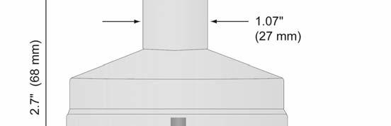


4 DIMENSIONS Step Three Series ULSL Series ULSM Series ULSS 4 of 30 MN Rev A
5 SAFETY PRECAUTIONS Step Four About this Manual: PLEASE READ THE ENTIRE QUICK START PRIOR TO INSTALLING OR USING THIS PRODUCT. This manual includes information on the Series ULS Ultrasonic Level Switch, controller and transmitter from Dwyer Instruments, Inc. Please refer to the part number located on the switch label to verify the exact model configuration, which you have purchased. User s Responsibility for Safety: Dwyer Instruments, Inc manufactures a broad range of level sensing technologies. While each of these sensors is designed to operate in a wide variety of applications, it is the user s responsibility to select a sensor model that is appropriate for the application, install it properly, perform tests of the installed system, and maintain all components. The failure to do so could result in property damage or serious injury. Proper Installation and Handling: Only professional staff should install and/or repair this product. Install the transmitter with the included FKM gasket and never over tighten the transmitter within the fitting. Always check for leaks prior to system start up. Wiring and Electrical: A supply voltage of 12 to 28 VDC is used to power the Series ULS. Electrical wiring of the transmitter should be performed in accordance with all applicable national, state, and local codes. Note: Series ULS uses latching relays. When power is removed to the sensor, the relays will remain in their last state. Ex: If the relay is energized, when power is removed, the relay will remain in an energized state. Material Compatibility: The enclosure is made of Polycarbonate (PC). The transducer is made of Polyvinylidene Fluoride (PVDF). Make sure that the model, which you have selected, is chemically compatible with the application media. Enclosure: While the transmitter housing is liquid resistant the Series ULS is not designed to be operational when immersed. It should be mounted in such a way that the enclosure and transducer do not come into contact with the application media under normal operational conditions. Safety Installation should be done by properly trained staff Supply voltage should never exceed a maximum of 28 VDC Make sure the sensor is chemically compatible with your application Design a fail safe system that accommodates the possibility of sensor and/or power failure This sensor should not be used in classified hazardous environments Make a Fail Safe System: Design a fail safe system that accommodates the possibility of transmitter and/or power failure. Dwyer Instruments, Inc recommends the use of redundant backup systems and alarms in addition to the primary system. Flammable, Explosive or Hazardous Applications: Series ULS should not be used within classified hazardous environments. Warning: Always use the FKM gasket when installing the Series ULS, and make sure that all electrical wiring of the switch is in accordance with applicable codes. Rev 5 MN of 30
6 COMPONENTS Step Five Series ULS is offered in different models. Depending on the model purchased, you may or may not have been shipped all the components shown below. You do however, need a Series ULS, USB Fob and FKM gasket to configure, install and operate Series ULS. P/N Max. Range Dead Band Thread Fob * Outputs ULSS (1.25 m) 2 (5cm) 1 NPT No Fob 1,2 ULSS (1.25 m) 2 (5cm) 1 NPT Fob Included 1,2 ULSS (1.25 m) 2 (5cm) 1 G No Fob 1,2 ULSS (1.25 m) 2 (5cm) 1 G Fob Included 1,2 ULSM (3.0 m) 4 (10cm) 1 NPT No Fob 1,2 ULSM (3.0 m) 4 (10cm) 1 NPT Fob Included 1,2 ULSM (3.0 m) 4 (10cm) 1 G No Fob 1,2 ULSM (3.0 m) 4 (10cm) 1 G Fob Included 1,2 ULSL (5.5 m) 8 (20cm) 2 NPT No Fob 1,2 ULSL (5.5 m) 8 (20cm) 2 NPT Fob Included 1,2 ULSL (5.5 m) 8 (20cm) 2 G No Fob 1,2 ULSL (5.5 m) 8 (20cm) 2 G Fob Included 1,2 FKM Gasket *Outputs o ULS ACC SGK used with ULSS series ma, loop powered output o ULS ACC MGK used with ULSM series 2. 4 SPST 60 VA relays o ULS ACC LGK used with ULSL series USB Fob o Part# ULS ACC USB Quick Start Guide 6 of 30 MN Rev A
7 GETTING STARTED Step Six Series ULS is configured through ULSX CAL, a PC software program. ULSX CAL is a free download from Dwyer Instrument, Inc s website. You must download and install ULSX CAL prior to plugging in the USB Fob. Please go to Inst.com/software, click on ULSX CAL. Please observe the following requirements for the ULSX CAL software: ULSX CAL System Requirements Windows(R) 2000, Windows(R) XP, Windows Vista (R), Windows(R) 7 32 or 64 bit operating system 1 USB 2.0 port 10 mb hard drive space 256 mb RAM Internet connection USB Fob Interface: The Series ULS communicates with ULSX CAL through a USB interface (p/n: ULS ACC USB) called a Fob. Before plugging your Fob into your computer s USB port, be sure that you have installed ULSX CAL on your computer. Connect the red, green, white and black wires from Series ULS into the correct terminals on the Fob. Tighten the screws on the terminals and plug your Fob into the USB port of your computer. Wiring identical for all series Use only the Red, Black, Green and White wires. The maximum cable distance between the computer and Series ULS is 15 (4.6 m). This only applies when configuring the Series ULS. Once Series ULS is configured and prior to installation, isolate the white and green wires from active power to prevent a short of the configuration circuit. When using the Fob, do not add VDC power. The Fob, when connected to the computer, will provide the required power to the Series ULS. Windows(R) is a registered trademark of Microsoft Corporation Windows Vista (R) is a registered trademark of Microsoft Corporation Rev 5 MN of 30

8 ULSX CAL Step Seven With Series ULS connected to your computer, open the ULSX CAL software by clicking on the ULSX CAL icon. Follow steps 1 3 to configure the transmitter. Click Help in the lower right hand corner and open the help menu of ULSX CAL for additional instructions on ULSX CAL. If you need additional assistance using ULSX CAL, please contact a Dwyer Instruments, Inc Applications Engineer at (800) Above Screen Capture is for the Series ULSS. 8 of 30 MN Rev A
9 ULSX CAL CONFIGURATION Step Seven This section of ULSX CAL is where you select the application s configuration settings. Start from the top and work to the bottom, choosing the selections that are applicable to your configuration. Not Applicable will automatically show when a selection doesn t apply to your configuration settings, and you may move on. All configuration settings must be selected or have Not Applicable before you can continue to the next step. Note: Pressing the Clear Screen button will reset the configuration table and allow access to all of the features. Number of Pumps: This feature allows you to select the number of pumps or valves used with Series ULS. This is the setting that activates the control capabilities of up to two relays. Control relays are often referred to as latching relays. o Switch/Alarms Only The relays will be standard single point relays (High and/or Low alarms). Relays are non latching. o 1 Pump/Valve One relay will be configured as a control or latching relay (relay will have a start level and a separate stop level). Use this setting to control one pump or valve for automatic filling or emptying of a tank. o 2 Pumps/Valves Two relays are configured as control or latching relays. Each relay will have a unique start level and a common stop level. Use this setting to control two pumps or valves for automatic filling or emptying of a tank. o 4 20mA Transmitter Only This setting will disengage all of the relays. Use this function if you are not using any relays and using only the 4 20 ma current output. Note: Right click on any menu that you may have questions on to open the help menu. Note: To reset, press the Clear Screen button. Rev 5 MN of 30
. You cannot set one relay for fill and the other for empty.")
10 ULSX CAL CONFIGURATION (continued) Step Seven Pump/Valve Action: This feature allows you to select if the pumps or valves will be used to automatically fill or empty the tank. For 2 Pump/Valve mode, both devices must be the same (automatic fill or empty). You cannot set one relay for fill and the other for empty. o Empties Tank Will set relay(s) to automatically empty a tank. Start level will be above the Stop level for each relay. o Fills Tank Will set relay(s) to automatically fill a tank. Start level will be below the Stop level for each relay. o Not Applicable Appears when this function is not available (such as when Switch/Alarms Only or 4 20mA Transmitters Only are selected). Empties Tank (Auto Empty) Fills Tank (Auto Fill) Note: Right click on any menu that you may have questions on to open the help menu. Note: To reset, press the Clear Screen button. 10 of 30 MN Rev A
11 ULSX CAL CONFIGURATION (continued) Step Seven Pump/Valve Mode: This feature allows you to select the mode for a control or latching relay. Pump/Valve mode is not active for Switch/Alarms Only or 4 20 ma Transmitter Only. o Simplex Allows for the relay to be used as an automatic fill or empty. This is the default and only configuration when 1 Pump/Valve is selected. o Simplex used to Empty Tank (example) o Lead/Lag Allows for the two relays to have unique start levels and a common stop level. The first relay will be identified as the lead relay and the second relay as the lag. Each time the lead level is reached, the first relay will always start. The lag relay will only start when the lag level is reached. All relays will stop at the common off level. o Lead/Lag used to Empty Tank (example) o Duplex Allows for the two relays to have two different start levels, a common stop level and will alternate the relays when the first start level is reached. The two relays will alternate each time the lead level is reached and the remaining relay will start when the lag level is reached. All relays will stop at the common off level. o Duplex used to Empty Tank (example) o Not Applicable Appears when this function is not available (such as when Switch/Alarms Only or 4 20mA Transmitters Only are selected). Note: Right click on any menu that you may have questions on to open the help menu. Note: To reset, press the Clear Screen button. Rev 5 MN of 30
12 ULSX CAL CONFIGURATION (continued) Step Seven Relay Fail Safe: This feature allows you to select the fail safe state for the relays. When the sensor regains signal, the output current will revert back to the current level condition. o Relays Off The relays will revert to the OFF state. Appears when Switch/Alarms Only is selected. o Relays On The relays will revert to the ON state. Appears when Switch/Alarms Only is selected. o Hold State The relay(s) will remain in the same state as the last echo detected. When the sensor regains signal, the relays will revert to the level when the signal was regain. o Pump/Valves Off The relays will revert to the OFF state. Appears when 1 Pump/Valve or 2 Pumps/Valves are selected. o Pump/Valves On The relays will revert to the ON state. Appears when 1 Pump/Valve or 2 Pumps/Valves are selected. o Not Applicable Appears when this function is not available (such as when Transmitters Only are selected). Note: Right click on any menu that you may have questions on to open the help menu. Note: To reset, press the Clear Screen button. 12 of 30 MN Rev A

13 ULSX CAL CONFIGURATION (continued) Step Seven Switch/Alarm Configuration: This feature allows you to select the operation for the switches / alarms (used as a high or low alarm). This setting adjusts the number of available relays based upon the previous settings. o No Alarm Turns off all of the remaining relays. o High Alarm Options Set from 1 to 4 High Alarms (1 High, 2 High, 3 High, 4 High). o Low Alarm Options Set from 1 to 4 Low Alarms (1 Low, 2 Low, 3 Low, 4 Low). o Combination Alarms Set a combination of High and Low Alarms (1 Low 1 High, 1 Low 2 High, 2 Low 1 High, 2 Low 2 High, 1 Low 3 High, 3 Low 1 High). o Not Applicable Appears when this function is not available (such as when Transmitters Only is selected). High Alarm Options Low Alarms Options Combination Alarms (4 High) (4 Low) (2 High and 2 Low) Note: Right click on any menu that you may have questions on to open the help menu. Note: To reset, press the Clear Screen button. Rev 5 MN of 30

14 ULSX CAL CONFIGURATION (continued) Step Seven Switch Hysteresis/Dead band: This feature allows you to select a hysteresis or dead band for the remaining high and/or low alarms. o Options for Hysteresis/Dead band No Hysteresis, ¼, ½, 1, 2, ½ cm, 1cm, 2 cm, 5 cm or Not Applicable. o High Alarms Relay activates above set point. Relay will deactivate when level goes below the set point plus the value of the hysteresis. o Low Alarms Relay activates below set point. Relay will deactivate when level goes above the set point plus the value of the hysteresis. High Alarm w/ Hysteresis Low Alarm w/ Hysteresis Note: Right click on any menu that you may have questions on to open the help menu. Note: To reset, press the Clear Screen button. 14 of 30 MN Rev A
15 ULSX CAL CONFIGURATION (continued) Step Seven Loop Fail Safe: This feature allows you to select the fail safe current output if the sensor fails to detect a return signal. When the sensor regains signal, the output current will revert back to the current level condition. o Hold Last Value The output will remain in the same state as the last echo detected. Example: If the output was 6.7 ma just prior to the lost signal, the device will continue to output 6.7 ma. Sensor will indicate the level when signal was regain. o Empty The output will revert to the current value for an empty condition. When 4 ma at Bottom is selected, the sensor will output 4 ma when a fail safe condition occurs. If 20 ma at Bottom is selected, the sensor will output 20 ma when a fail safe condition occurs. o Full The output will revert to the current value for a full condition. When 4 ma at Bottom is selected, the sensor will output 20 ma when a fail safe condition occurs. If 20 ma at Bottom is selected, the sensor will output 4 ma when a failsafe condition occurs. o Overfill (21 ma) The output current will go to 21 ma when the return signal is lost. o Overfill (22 ma) The output current will go to 22 ma when the return signal is lost. Output at Empty: This feature allows you to select the orientation of the 4 to 20 ma output (4 to 20 ma or 20 to 4 ma). Choose which output setting best fits the application. Typical installations are set with 4 ma at Bottom. This will not affect the performance of the sensor other than the output of the Series ULS. ULSX CAL s factory default is 4 ma at bottom and 20 ma at top. When connecting your sensor to a display, you must account for your output settings. o 4 ma at Bottom The output current will be 4 ma when the sensor measures an empty tank and 20 ma when the sensor measures a full tank. o 20 ma at Bottom The output current will be 20 ma when the sensor measures an empty tank and 4 ma when the sensor measures a full tank. Note: Right click on any menu that you may have questions on to open the help menu. Note: To reset, press the Clear Screen button. Rev 5 MN of 30
16 ULSX CAL TANK LEVELS / WRITE TO UNIT Step Seven ULSX CAL Tank Levels: This section of ULSX CAL is where you enter application measurement values. This applies to all versions of the Series ULS. You must enter the Sensor Height and Fill Height values. For the Series ULSS, ULSM and ULSL, the Sensor Height and Fill Height values determine the operational range for the 4 20 ma output. Sensor Height: Distance from the bottom of the tank to the bottom of the transducer. Fill Height: Distance from the bottom of the tank to the maximum liquid height. ULSX CAL Relay Values: (Series ULSS, ULSM and ULSL only): This section of ULSX CAL is where you enter the operational values for relays. You must enter values within all of the fields shown. The value fields shown are based upon the configuration of the Series ULS. All values must be in the units of operation selected above and are based upon units of liquid. All relay values must be greater than Liquid Empty (0) and less than Liquid Full (Fill Height). Example: This sample shows 4 High Level Alarms. As the level increases from the bottom up, each alarm will activate at 4 increments. Example: This sample shows a 2 Pump Lead/Lag operation with a High and Low alarm. The pumps will automatically empty the tank and the alarms will activate if the level gets too high or low. 16 of 30 MN Rev A

17 ULSX CAL WRITE TO UNIT After you have entered configurations and tank values, click Write to Unit and send the configuration to your Series ULS. Now use ULSX CAL s file management features to save your configuration by clicking Save Config File and print your wiring diagram by clicking Wiring Diagram. Write to Unit Wiring diagram Step Seven Save Config File Wiring Diagram Sample Diagram will change based upon the configuration of the Series ULS, use ULSX CAL to view appropriate wiring diagram. Wiring Series ULS: Once Series ULS has been installed, follow the Wiring Diagram provided by the ULSX CAL software. A typical wiring diagram is shown above. Dwyer Instruments, Inc recommends using a qualified licensed electrician to wire Series ULS and your application s components. Configure your Series ULS with ULSX CAL and use the wiring diagram button to view the appropriate diagram. Each configuration will have its own unique diagram. The diagram above is only a sample and should not be used as a wiring diagram. Always use stepper relays between the sensor and external loads. For DC circuits use a catch diode such as 1N4148, shown on the wiring diagram shown above and supplied by ULSX CAL. Once Series ULS is configured, isolate the white and green wires from active power to prevent a short of the configuration circuit. Rev 5 MN of 30
18 WIRING Step Eight Wire Connections: Red & Black: Red and Black leads are for connection to a VDC power supply or to a 4 20 ma loop power source (Series ULSS, ULSM & ULSL only). The red and black wires can be extended up to 1,000 feet using a 22 gauge or larger wire, however do not extend the green and white wires. White & Green: White and Green leads are reserved for use with ULSX CAL and should not be connected during usage in the application. These wires should not be connected to ULSX CAL while power is supplied from any source other than the ULS ACC USB Fob. The maximum cable distance between the computer and Series ULS is 15. Never allow the white or green wires to touch any power supply. Blue, Orange, Yellow, Purple & Brown: Blue, Orange, Yellow & Purple wires are the relay contacts (normally open) from each of the relays respectively. The Brown wire is the common for all the relays. Relay selection is determined by the configuration in ULSX CAL. Note: Series ULS uses latching relays. When power is removed to the sensor, the relays will remain in their last state. Ex: If the relay is energized, when power is removed, the relay will remain in an energized state. General notes for electrical connections, usage and safety: Where personal safety or significant property damage can occur due to a spill, the installation must have a redundant backup safety system installed. Wiring should always be completed by a licensed electrician. Supply voltage should never exceed 28 VDC. Always use stepper relays between the sensor and external loads. For DC circuits use a catch diode such as 1N4148, shown on previous page. Protect the sensor from excessive electrical spikes by isolating the power, whenever possible. The sensor materials must be chemically compatible with the liquids to be measured. Design a fail safe system for possible sensor and/or power failure. Never use the sensor in environments classified as Hazardous. 18 of 30 MN Rev A
 for AC circuits.")
19 WIRING Step Eight Switching Inductive Loads: The use of suppressors (snubbers) is strongly recommended when switching inductive loads to prevent disrupting the microprocessor s operation. The suppressors also prolong the life of the relay contacts. Suppression can be obtained with a catch diode for DC circuits and a resistor capacitor (RC) for AC circuits. Catch Diode Always use stepper relays between the sensor and external loads. For DC circuits use a catch diode such as 1N4148, shown on left. Refer to the following circuits for RC network assembly and installation: Choose R and C as follows: R: 0.5 to 1 Ohms for each volt across the contacts C: 0.5 to 1 μf for each amp through closed contacts Notes: 1. Use capacitors rated for 250 VAC. 2. RC networks may affect load release time of solenoid loads. Check to confirm proper operation. 3. Install the RC network at the meters relay screw terminals. An RC network may also be installed across the load. Experiment for best results. Voltage Output: Series ULS can be used as a 0 to 5 or 0 to 10 VDC output device. A resistor will need to be added to the circuit to enable a voltage output (refer to the wiring diagram below). 0 5 VDC output o Add a 250 Ohm resistor o Actual output will be 0.8 to 5 VDC 0 10 VDC output o Add a 500 Ohm resistor o Actual output will be 2 to 10 VDC When using ULSX CAL, under Number of Pumps, select 4 20 ma Transmitter Only to simplify the configuration in ULSX CAL. Rev 5 MN of 30

 reducer bushing. Mounting Guide 1. Do not mount at an angle 2.")

 Do not install with objects in the beam. Do not install in applications with vacuum.")
20 INSTALLATION Step Nine The Series ULS should always be mounted perpendicular to the liquid surface and installed using the provided FKM mounting gasket. Make sure that the fitting and transmitter threads are not damaged or worn. Always hand tighten the transmitter within the fitting. Perform an installed leak test under normal process conditions prior to system start up. Note: The preferred mounting fitting for the Series ULSS & ULSM is the ULS ACC 121 (2 thread x 1 thread) reducer bushing. Mounting Guide 1. Do not mount at an angle 2. Liquid should never enter the dead band 3. Side Wall: a. Mount at least 2 from the side wall b. For Series ULSL mount at least 3 from the side wall 4. Do not mount where obstacles will intrude on sensor s beam width a. See Specifications, Step Two 5. Do not mount in a vacuum 6. Avoid mounting in the center of a dome top tank. 7. In cone bottom tank, position the sensor over the deepest part of the tank. Do not install at angle relative to the liquid. Do not install within 2 of tank sidewall. (3 for Series ULSL) Do not install with objects in the beam. Do not install in applications with vacuum. Installation in existing fittings: If the existing fitting is larger than the threads of the Series ULS, select a reducer bushing such as the ULS ACC 121 (2 thread x 1 thread) or ULS ACC 131 (3 thread x 2 thread). Metal Tanks (Series ULSS & ULSM): Dwyer Instruments, Inc ultrasonic transmitters have been optimized for use in non metallic fittings. 1. For best performance, avoid the use of metallic fittings. a. Use a plastic 2 x 1 reducer bushing, such as the ULS ACC 121 or a plastic 1 flange, such as the ULS ACC 312 for metallic tanks. 2. While installations directly into a 1 metal fitting are not recommended, acceptable results may be obtained if the 1 fitting is a half coupling in form and the outer diameter of the coupling is tightly wrapped in vinyl tape to dampen vibrations. 20 of 30 MN Rev A

 styles and/or pipe stops forward of the installed transducer. c. Always mount the tank adapter so the majority of fitting is outside the tank. i. Never mount the tank adapter upside down or the bulk of the material is inside the tank.")
21 INSTALLATION Step Nine Fitting Selection: Check the part number to determine the required fitting mount size and thread type. Series ULS is commonly installed in tank adapters, flanges, brackets or standpipes. Note: Always include the gasket when installing the Series ULS. 1. Tank Adapter: Select a tank adapter fitting, such as the ULS ACC 410 for the Series ULSS & ULSM or the ULS ACC 420 for the Series ULSL. a. For best results, select a 2 tank adapter and add a reducer bushing such as the ULS ACC 121, thread x thread, reducer bushing. b. Avoid tank adapter (thread x thread) styles and/or pipe stops forward of the installed transducer. c. Always mount the tank adapter so the majority of fitting is outside the tank. i. Never mount the tank adapter upside down or the bulk of the material is inside the tank. 2 Tank Adapter Socket x Thread (ULS ACC 420) Tank Adapter (ULS ACC 420) w/ 2 x 1 Reducer Bushing (ULS ACC 121) Tank Adapter Thread x Thread Do not use thread x thread 2. Riser: Installations with tall, narrow risers can impede the acoustic signal. a. Series ULSL: 2 (5 cm) diameter risers should be no taller than 4 (10 cm). Larger diameter risers should be no taller than 12 (30.5 cm). b. Series ULSS & ULSM: Note: Do not exceed the dimensions listed above Rev 5 MN of 30
. c.")
 1 Flange w/ thread in plane 2 Flange w/ reducer bushing (ULS ACC 121) Do not use thread in plane 4.")
22 INSTALLATION Step Nine 3. Flange (Series ULSS & ULSM): If installing on a flange, select a flange with a thread that is above the plane of the flange, such as the ULS ACC 312. a. The Series ULSL works well with flange installations. b. Avoid the use of blind flanges with tapped threads or flanges where the threads are even with the plane of the flange, such as the Banjo 1" Poly ANSI Flange (series AF100). c. Use a flange with a 2 thread and add a 2 to 1 reducer bushing to complete the installation. 2 Flange w/ thread out of plane (ULS ACC 312) 1 Flange w/ thread in plane 2 Flange w/ reducer bushing (ULS ACC 121) Do not use thread in plane 4. Side Mount Bracket: For installations in open tanks and sumps, use the ULS ACC 510 or ULS ACC 520 side mount bracket. a. For the Series ULSS & ULSM, order the ULS ACC 510, which includes a 2 x 1 Reducer Bushing. b. For the Series ULSL, order the ULS ACC 520 side mount bracket. 22 of 30 MN Rev A
 fitting or the ULS ACC 221 (2 S x 1 T) fitting.")
23 INSTALLATION Step Nine 5. Stand Pipe: A standpipe maybe used to dampen turbulence or when foam is present in the application. a. Pipe can be made of any material. b. Select a minimum 3 ID pipe for the stand pipe. i. A 2 pipe is usable with the Series ULSS & ULSM, but is the minimum. ii. Pipes larger than 3 can also be used. c. Use a coupling and reducer bushing to attach the Series ULS to the pipe. i. Be sure to use a plastic reducing bushing such as ULS ACC 121 (2 T x 1 T) fitting or the ULS ACC 221 (2 S x 1 T) fitting. ii. For the Series ULSL, use a reducer bushing such as ULS ACC 131 (3 T x 2 T) fitting or the ULS ACC 231 (3 S x 2 T) fitting. d. The pipe length should run the measurement span and the bottom of the pipe should remain submerged at all times to prevent foam from entering the pipe. e. Cut a 45 notch at the bottom of the pipe and drill a 1/4 pressure equalization hole in the dead band. f. The pumps should not drive liquid past the open end of the stand pipe which causes the liquid in the pipe to oscillate. Rev 5 MN of 30
24 ADVANCED FEATURES Step Ten This tool is designed to help solve operational issues. Changing these setting will alter the performance of your unit. Please read through this HELP file to assist you in making adjustments or if you are still unclear about a specific issue, please contact Dwyer Instruments, Inc, Applications Engineering. Note: When the Advanced Button is highlighted with a RED border, this indicates you have selected an advanced feature. 24 of 30 MN Rev A

25 ADVANCED FEATURES Step Ten Increase Output Filtering: Placing a check mark in the box will increase the filtering (averaging) of the analog output. Use this filter if the 4 to 20 ma output requires a smooth output for the application such as open channel flow measurement. Decrease Output Filtering: Placing a check mark in the box will eliminate all filtering (averaging) of the analog output. Enables a pulse by pulse level reading. Use this filter to see changes in level after every sound pulse. Note: Never check increase output filtering and decrease output filtering at the same time. Stabilize Output in Dead band: Placing a check mark in the box will activate a filter to hold the output at Full Level if the level enters the dead band of the Series ULS. This filter requires the level to leave the dead band at a smooth and steady rate. Turn OFF Fast Level Changes: Placing a check mark in the box will turn off the filter enabling fast level changes. Use this filter if your application has very smooth, slow and steady level changes. The filter instructs Series ULS to look only for small incremental changes in level. Turn ON Noisy Mount Start Filter: Placing a check mark in the box will activate a filter that reduces sound interference from the installation mount. Use this filter if the Series ULS will not go to full range in the installation. Invert Relay States: Placing a check mark in any of the four boxes will reverse the state of that relay. For example, if relay 4 is a high alarm that energizes above 50 of liquid, checking the invert box will reverse so the relay will energize when it is below 50 of liquid. Inverting the relay will also invert the fail safe of the relay. If the relay is fail safe On, inverting the relay will make it fail safe Off. Fail Safe will also invert unless you check below: This button will not invert the fail safe when a relay is inverted. Rev 5 MN of 30
26 APPENDIX Step Eleven Updating ULSX CAL Software: ULSX CAL software can be updated directly from the software. Simply click on the Updates Tab at the top of the window and press the Download button. Make sure that your computer has access to the Internet. If not, an error window will appear. When the Download button is pressed, the software will check the version of software you are using with the most recent version at Dwyer Instruments, Inc. If the versions are similar, a window indicating that the most recent version is installed. If not, then a window will appear asking to download the latest version. Follow the instructions for installing the latest version. 26 of 30 MN Rev A


27 APPENDIX Step Eleven Updating Transmitter Firmware: ULSX CAL software can also be used to update firmware inside the Series ULS transmitter. This feature allows the transmitter to be updated when new features are added. First open ULSX CAL with an Series ULS transmitter connected and the latest version of ULSX CAL installed to your PC. Click on the Updates Tab and then click on Select Program to select the firmware update. Select the latest version of the firmware file and click on OK. Confirm that the address is correct and then click on Update Sensor to begin the firmware update. This step should take less than 1 minute. You can follow the progress with the status bar to the right of the Update Sensor button. When completed, click on the Configuration tab to configure the transmitter. Remember, when the firmware has been updated, the unit will return to its original factory settings. If there is a communication interruption during the update, the process will stop. It is OK to click on Update Sensor again to start the process over again. Rev 5 MN of 30
 away and 20 ma @ 2 (5 cm) away from sensor.")
28 TROUBLESHOOTING Step Twelve Factory Default: Pressing the Factory Config button in the Configuration menu will return the screen to the following settings. Out of the box, the Series ULS will output a 4 20 ma output that is maximized for its operational range. Series ULSS (1.25 m) away and 20 2 (5 cm) away from sensor. Series ULSM (2.5 m) away and 20 4 (10 cm) away from sensor. Series ULSL (5.5 m) away and 20 8 (20 cm) away from sensor. Factory Defaults Table Testing the Transmitter 1. Connect a multimeter in series with the black wire to read the current output. 2. Verify that the current increases (tank filling) and decreases (tank emptying) appropriately in the calibrated span. 3. If not, carefully observe and attempt to correlate any installation, level or application event for more specific troubleshooting direction. 28 of 30 MN Rev A
29 TROUBLESHOOTING PROBLEM Transmitter indicates a current of 0 ma Transmitter jumps to a current reading between 19 and 20 ma Transmitter indicates a current over 23 ma Transmitter always jumps to the LOST condition Output of transmitter is opposite of the level of liquid No Unit Detected in ULSX CAL Internet error. The server name or address could not be resolved. Cannot access some of the features in Configuration Relay closes, but does not open again Relay chatters on and off repeatedly Step Twelve SOLUTION Check the wiring for an open circuit. An open circuit is the most common issue with a 0 ma signal. Check the installation of the transmitter. Bad installation fittings will cause false signals near the top of the tank, which typically translates to a signal between 19 and 20 ma. Also look for interference just below the transmitter. If the transmitter is installed in a metal fitting, switch to a plastic fitting. Immediately check the wiring for a short circuit. The Series ULS is current limited to 22 ma. Anything above 23 ma indicates a short circuit. Check the dimensional configuration (Height and Fill H) of the Series ULS. Make sure that the Fill H setting corresponds to the full level of liquid (from the bottom up) and not the distance from the transmitter to the liquid (top down). Check the Output at Empty Setting. ULSX CAL cannot detect a Series ULS connected to the computer. Check that the Fob is connected to the USB port. Check that all four wires (Red, Black, White and Green) are securely attached to the Fob. Check in Device Manager that drivers are present under Universal Serial Bus controllers. This is a warning indicating the computer configuring Series ULS is not connected to the internet. Click OK to continue. Dwyer Instruments, Inc recommends being connecting to the internet for all configurations. Not being connected to the internet will not prevent the Series ULS from being configured. As choices are made in Configuration, ULSX CAL will begin to eliminate functions that are no longer active. To reset Configuration or get access to all the features, click on the Clear Screen button. An inductive kick may be holding the relay closed. If switching 24 VDC, make sure a diode has been installed to act as a snubber (see Step Eight). Note: Series ULS uses latching relays. When power is removed to the sensor, the relays will remain in their last state. Ex: If the relay is energized, when power is removed, the relay will remain in an energized state. Most likely the turbulence in the tank is causing the chatter. Increase the Hysteresis setting to correct. Rev 5 MN of 30
30 MAINTENANCE & REPAIR Step Thirteen MAINTENANCE/REPAIR Upon final installation of the Series ULSS, ULSM or ULSL, no routine maintenance is required. The Series ULSS, ULSM or ULSL is not field serviceable and should be returned is repair is needed (field repair should not be attempted and may void warranty). WARRANTY/RETURN Refer to Terms and Conditions of Sale in our catalog or on our website. Contact customer service to receive a Return Goods Authorization number before shipping your product back for repair. Be sure to include a brief description of the problem plus any relevant application notes. Dwyer Instruments, Inc Attn: Repair Department 102 Highway 212 Michigan City, IN of 30 MN Rev A
EchoPod DL14, DL24 & DL34 Series Manual Revision A.3
 EchoPod DL14, DL24 & DL34 Series Manual Revision A.3 Flowline Inc. 10500 Humbolt Street Los Alamitos, CA 90720 Tel: (562) 598-3015 Fax: (562) 431-8507 www.flowline.com 31 MAR 11 EchoPod 1 of 29 Preface
EchoSonic. LU23, LU27, LU28 & LU29 Series Manual. Ultrasonic Liquid Level Transmitter
 EchoSonic Ultrasonic Liquid Level Transmitter LU23, LU27, LU28 & LU29 Series Manual Flowline, Inc. 10500 Humbolt Street, Los Alamitos, CA 90720 p 562.598.3015 f 562.431.8507 w flowline.com MN300610 Rev
EchoPod. DL10, DL14, DL24, DL34, DS14, DX10 Series Manual. Ultrasonic Liquid Level Transmitter, Switch and/or Controller
 EchoPod Ultrasonic Liquid Level Transmitter, Switch and/or Controller DL10, DL14, DL24, DL34, DS14, DX10 Series Manual Flowline, Inc. 10500 Humbolt Street, Los Alamitos, CA 90720 p 562.598.3015 f 562.431.8507
INTRODUCTION / TABLE OF CONTENTS
 1 2 INTRODUCTION / TABLE OF CONTENTS Step One An ultrasonic sound wave is pulse eight times per second from the base of the transducer. The sound wave reflects against the process medium below and returns
EchoPod. DL10, DL14, DL24, DS14 & DX10 Series Quick Start. DL14-00 Shown Flowline, Inc. All Rights Reserved Made in USA
 EchoPod Ultrasonic Level Switch, Controller & Transmitter DL10, DL14, DL24, DS14 & DX10 Series Quick Start DL14-00 Shown 2016 Flowline, Inc. All Rights Reserved Made in USA Flowline, Inc. 10500 Humbolt
LU27 Series Quick Start
 Ultrasonic Liquid Level Transmitter LU27 Series Quick Start 2016 Flowline, Inc. All Rights Reserved Made in USA Flowline, Inc. 10500 Humbolt Street, Los Alamitos, CA 90720 p 562.598.3015 f 562.431.8507
EchoPod. Technical Support. Model: DL14-(XX) Quick Start
 Quick Start") Technical Support For complete product documentation, video training, and technical support, go to www.flowline.com. For phone support, call 562-598-3015 from 8am to 5pm PST, Mon - Fri. (Please make sure
Technical Support For complete product documentation, video training, and technical support, go to www.flowline.com. For phone support, call 562-598-3015 from 8am to 5pm PST, Mon - Fri. (Please make sure
EchoPod. UG06 & UG12 Series Manual. Ultrasonic Level Transmitter
 EchoPod Ultrasonic Level Transmitter UG06 & UG12 Series Manual Flowline, Inc. 10500 Humbolt Street, Los Alamitos, CA 90720 p 562.598.3015 f 562.431.8507 w flowline.com MN310140 Rev A1 Introduction / Table
LU23, LU28 & LU29 Series Quick Start
 Ultrasonic Liquid Level Transmitter LU23, LU28 & LU29 Series Quick Start 2016 Flowline, Inc. All Rights Reserved Made in USA Flowline, Inc. 10500 Humbolt Street, Los Alamitos, CA 90720 p 562.598.3015 f
EchoPod. UG01 & UG03 Series Quick Start Flowline, Inc. All Rights Reserved Made in USA. Ultrasonic Liquid Level Switch, Controller & Transmitter
 EchoPod Ultrasonic Liquid Level Switch, Controller & Transmitter UG01 & UG03 Series Quick Start 2017 Flowline, Inc. All Rights Reserved Made in USA Flowline, Inc. 10500 Humbolt Street, Los Alamitos, CA
EchoPod. UG06 & UG12 Series Quick Start Flowline, Inc. All Rights Reserved Made in USA. Ultrasonic Liquid Level Transmitter
 EchoPod Ultrasonic Liquid Level Transmitter UG06 & UG12 Series Quick Start 2017 Flowline, Inc. All Rights Reserved Made in USA Flowline, Inc. 10500 Humbolt Street, Los Alamitos, CA 90720 p 562.598.3015
Configuring the Cost-Effective Ultrasonic Liquid Level Sensor
 June 11, 2013 Configuring the Cost-Effective Ultrasonic Liquid Level Sensor Overview The Flowline Ultrasonic Liquid Level Sensors are cost-effective sensors that can be used for small to medium capacity
XP88 & XP89 Series Quick Start
 Ultrasonic Liquid Level Transmitter XP88 & XP89 Series Quick Start 2016 Flowline, Inc. All Rights Reserved Made in USA Flowline, Inc. 10500 Humbolt Street, Los Alamitos, CA 90720 p 562.598.3015 f 562.431.8507
CRICKET Alphasonic Level Transmitter Model LA12 Owner s Manual
 Warranty, Service and Repair To register your product with the manufacturer, fill out the enclosed warranty card and return it immediately to: FLOWLINE Inc. 10500 Humbolt Street Los Alamitos, CA 90720
Switch-Pak. AU13, AV13 & AZ13 Series Owner s Manual. w/ Compact Relay Controller
 Switch-Pak w/ Compact Relay Controller AU13, AV13 & AZ13 Series Owner s Manual Flowline, Inc.. 10500 Humbolt Street, Los Alamitos, CA 90720. p 562.598.3015. f 562.431.8507. w flowline.com MN301430 Rev
LA19 Series Ricochet Battery Powered Level Transmitter and Display
 Warranty, Service & Repair To register your product with the manufacturer, fill out the enclosed warranty card and return it immediately to: Flowline Inc. 10500 Humbolt Street Los Alamitos, CA 90720. If
1' to 10' deep and 1' to 25' deep
 ULTRASONIC ECHO-SCALE TM SCALE: INDICATOR: ECHO-SCALE TM NONE PROVIDED electronic sensors for vessels 1' to 10' deep and 1' to 25' deep INSTALLATION & OPERATION s/n 1-800-893-6723 Fax: 925-686-6713 www.forceflow.com
Specifications - Installation and Operating Instructions Ø5 [127.00] 17/64 [6.91] 1-59/64 [48.89]
![Specifications - Installation and Operating Instructions Ø5 [127.00] 17/64 [6.91] 1-59/64 [48.89]](/thumbs/84/88997249.jpg "Specifications - Installation and Operating Instructions Ø5 [127.00] 17/64 [6.91] 1-59/64 [48.89]") Bulletin P-DM-1200 Series DM-1200 DigiMag Digital Differential Pressure and Air Flow Gage Specifications - Installation and Operating Instructions PRESSURE CONNECTIONS 21/64 [8.59] LONG Ø5 [127.00] 4-31/64
Bulletin P-DM-1200 Series DM-1200 DigiMag Digital Differential Pressure and Air Flow Gage Specifications - Installation and Operating Instructions PRESSURE CONNECTIONS 21/64 [8.59] LONG Ø5 [127.00] 4-31/64
EchoWave. LG10 & LG11 Series Manual. Guided Wave Liquid Level Transmitter
 EchoWave Guided Wave Liquid Level Transmitter LG10 & LG11 Series Manual Flowline, Inc. 10500 Humbolt Street, Los Alamitos, CA 90720 p 562.598.3015 f 562.431.8507 w flowline.com MN300840 REV A8 Introduction
Smart Trak. AU18, AU28, AU38, AU48, AV16, AV26, AV36, AV46, AZ18, AZ28, AZ38 & AZ48 Series Owner s Manual. w/ Compact Junction Box
 Smart Trak w/ Compact Junction Box AU18, AU28, AU38, AU48, AV16, AV26, AV36, AV46, AZ18, AZ28, AZ38 & AZ48 Series Owner s Manual Flowline, Inc.. 10500 Humbolt Street, Los Alamitos, CA 90720. p 562.598.3015.
CLA-VAL e-drive-34. User Manual. Motorised Pilots. CLA-VAL Europe LIN072UE - 04/16
 User Manual CLA-VAL Europe www.cla-val.ch cla-val@cla-val.ch 1 - LIN072UE - 04/16 Table of Contents 1 Introduction... 3 1.1 Precautions Before Starting... 3 1.2 Troubleshooting... 3 1.3 General Disclaimer...
ITCEMS950 Idle Timer Controller - Engine Monitor Shutdown Isuzu NPR 6.0L Gasoline Engine
 Introduction An ISO 9001:2008 Registered Company ITCEMS950 Idle Timer Controller - Engine Monitor Shutdown 2014-2016 Isuzu NPR 6.0L Gasoline Engine Contact InterMotive for additional vehicle applications
INSTALLATION/OPERATING INSTRUCTIONS TSC
 INSTALLATION/OPERATING INSTRUCTIONS TSC Two-Stage Set Point Control with External Activation Two-Stage Heating (Rotation Included) Two-Stage Cooling (Rotation Included) Change-Over Control (Heat/Cool)
DWYER INSTRUMENTS, INC. Phone: 219/ P.O. BOX 373 MICHIGAN CITY, IN 46361, U.S.A. Fax: 219/
 Series 43000 Capsu-Photohelic Pressure Switch/Gage Specifications - Installation and Operating Instructions Bulletin B-34 Ø4-3/4 [120.65] 3-7/8 SQ [98.43] 3/4 CONDUIT 4-3/8 [111.13] HOUSING REMOVAL 3-1/16
Application Engineering
 Application Engineering February, 2009 Copeland Digital Compressor Controller Introduction The Digital Compressor Controller is the electronics interface between the Copeland Scroll Digital Compressor
K10 Intrinsically Safe Electro-Pneumatic Positioner Operating Manual
 K0 Intrinsically Safe Electro-Pneumatic Positioner Operating Manual Pneumatic Connection Outlet Port Gauge Single Acting Actuator (Spring Return): For single acting actuators Outlet Port 2 is to be plugged.
Rosemount 8750WA Magnetic Flowmeter System For Water and Wastewater Industries
 Product Data Sheet January 214 813-1-475, Rev FA Rosemount 875WA Magnetic Flowmeter System For Water and Wastewater Industries THE 875WA MAGNETIC FLOWMETER Rosemount reliability in a customized offering
Switch Pro w/ Compact Junction Box A_1_ Series Owner s Manual
 Warranty, Service & Repair To register your product with the manufacturer, go to the Flowline website for on-line registration. The website address is as follows: www.flowline.com On-line Warranty Registration
DWYER INSTRUMENTS, INC. Phone: 219/ P.O. BOX 373 MICHIGAN CITY, INDIANA 46360, U.S.A. Fax: 219/
 Series DBOB-Continuous Level Measuring System Bulletin L-DBOB Specifications - Installation and Operating Instructions 7-9/32 [185.00] 5-45/64 [145.00] 8-21/32 [220.00] 5-45/64 [145.00] 10-1/32 [255.00]
Application Engineering
 Application Engineering March 2011 Copeland Digital Compressor Controller Introduction The Digital Compressor Controller is the electronics interface between the Copeland Scroll Digital compressor or the
DIESEL Engine Fire Pump Controllers Features
 1-1 Printer / Recorder The industrial grade thermal printer is housed in a rugged steel enclosure within the controller. The on/off switch, feed and reset buttons are front accessible. A bi-color status
Product Information Page
 PROGRAMMING GC31 PRESSURE TRANSMITTER TO MONITOR AND CONTROL A HYDRAULIC PRESS PIP #: TR-PI-104 The GC31 differential pressure transmitter is compact, flexible and supports numerous pressure applications
User Manual. Liquid Level Sensor. Unit 600 Ampress Park Lymington, Hampshire SO4 l SLW United Kingdom
 7010 Liquid Level Sensor User Manual Gill Sensors & Controls Limited Unit 600 Ampress Park Lymington, Hampshire SO4 l SLW United Kingdom Tel: +44 (0) 1590 613 900 Fax +44 (0) 1590 613 901 info@gillsc.com
Product Guide: Series III Pump Control Board Set (RoHS)
") revised 04/08/10 Description: The Series III Pump Control Board Set provides motor drive and pump control for a wide assortment of pumps from Scientific Systems, Inc. The assembly consists of two circuit
revised 04/08/10 Description: The Series III Pump Control Board Set provides motor drive and pump control for a wide assortment of pumps from Scientific Systems, Inc. The assembly consists of two circuit
ELECTRIC ACTUATOR 94OE IOM. E024, EO25, E026, EO29 & E030 Installation Operation and Maintenance Instructions TABLE OF CONTENTS
 ELECTRIC ACTUATOR E024, EO25, E026, EO29 & E030 Installation Operation and Maintenance Instructions TABLE OF CONTENTS 94OE IOM Electric Actuator Specifications...2 Overview...3 Actuator Wiring Diagrams...4
Overview of operation modes
 Overview of operation modes There are three main operation modes available. Any of the modes can be selected at any time. The three main modes are: manual, automatic and mappable modes 1 to 4. The MapDCCD
GTFM IV. Operation / Installation Manual. Gas Turbine Flow Monitor. Computer Weld Technology, Inc. Manual Part Number: A8M5010 Revised: June 26, 2008
 Computer Weld Technology, Inc. 10702 Old Bammel N Houston Rd. Houston, TX 77086 Phone: (713) 462-2118 Fax: (713) 462-2503 Email: cwt@cweldtech.com GTFM IV Gas Turbine Flow Monitor Operation / Installation
U00X ULTRASONIC LEVEL SWITCH. Ultrasonic Liquid Level Switches INSTALLATION AND OPERATIONS MANUAL. For Models: U002, U003 & U004
 U00X ULTRASONIC LEVEL SWITCH INSTALLATION AND OPERATIONS MANUAL Ultrasonic Liquid Level Switches For Non-Hazardous Locations For Models: U002, U003 & U004 READ THIS MANUAL PRIOR TO INSTALLATION This manual
AMI. American Magnetics, Inc. Excellence in Magnetics and Cryogenics
 Cryogenic Liquid Level Instruments Versatile Reliable Affordable AMI American Magnetics, Inc. Excellence in Magnetics and Cryogenics A Versatile Level Measurement System... A Variety of Liquids Nitrogen
METROLOGIC INSTRUMENTS, INC. MX001 Industrial Control Interface Installation and User s Guide
 METROLOGIC INSTRUMENTS, INC. MX001 Industrial Control Interface Installation and User s Guide Copyright 2007 by Metrologic Instruments, Inc. All rights reserved. No part of this work may be reproduced,
UTM10 Series Ultrasonic Transit-time Flowmeters
 Page 1 of 5 TI-P197-01 MI Issue 1 UTM10 Series Ultrasonic Transit-time Flowmeters Description UTM10 ultrasonic flow and energy meters clamp onto the outside of pipes and do not make contact with the internal
LTX RF LEVEL SENSOR. Instruction Manual
 LTX RF LEVEL SENSOR Instruction Manual FOR MODELS LTX01, LTX02, LTX05 Intempco Document No: LTX - M01 Rev. 1 Issue Date: April 2005 LTX01 RF LEVEL SENSOR USER MANUAL Software Rev : Rev. Date : June 2004
Installation and Operation Instructions DLP Series
 Installation and Operation Instructions DLP Series PRECAUTIONS Figure 1: DLP Dimensions and Hardware REMOVE POWER BEFORE WIRING. NEVER CONNECT OR DISCONNECT WIRING WITH THE POWER APPLIED. DO NOT ALLOW
F-4600 INLINE ULTRASONIC FLOW METER Installation and Operation Guide
 F-4600 INLINE ULTRASONIC FLOW METER Installation and Operation Guide 11451 Belcher Road South, Largo, FL 33773 USA Tel +1 (727) 447-6140 Fax +1 (727) 442-5699 1054-7 / 34405 www.onicon.com sales@onicon.com
SmartBob AO. BinMaster: Division of Garner Industries 7201 N. 98th St., Lincoln, NE
 BinMaster: Division of Garner Industries 7201 N. 98th St., Lincoln, NE 68507 402-434-9102 email: info@binmaster.com www.binmaster.com OPERATING INSTRUCTIONS PLEASE READ CAREFULLY 925-0312 Rev B TABLE OF
Continental Hydraulics Installation Manual CEM-AA-A
 Continental Hydraulics Installation Manual CEM-AA-A Description: This power amplifier drives either single or dual solenoid proportional valve coils up to 2.6A. It is suitable to control current to proportional
Idle Timer Controller - A-ITC620-A Chevrolet Express/GMC Savana
 An ISO 9001:2008 Registered Company Idle Timer Controller - A-ITC620-A1 2009-2018 Chevrolet Express/GMC Savana Contact InterMotive for additional vehicle applications Introduction The A-ITC620-A1 is an
Signet Pressure Transmitter
 Signet 8450 Pressure English 8450.090 8450.090 Rev. G /06 English CAUTION! Remove power to unit before wiring input and output connections. Follow instructions carefully to avoid personal injury. Contents
Model 2100 Installation Guide
 Model 2100 Installation Guide 2001 Directed Electronics, Inc. Vista, CA N2100 4-01 Rev. N/C 1.1 table of contents What Is Included..................... 2 Wiring Quick Reference Guide............ 3 Primary
Figure 1: WPR2 Dimensions and Hardware
 Installation and Operation Instructions WPR2 Series (Max. Line Pressure < 300 PSI) Wet to Wet Differential Pressure Ø0.200" 2.60" 4.47" 5.47" 5.28" 3.00" Precautions Figure 1: WPR2 Dimensions and Hardware
ELECTRIC ACTUATOR HVAC/BAC ELECTRIC IOM. E024, EO25, E026, EO29 & E030 Installation Operation and Maintenance Instructions TABLE OF CONTENTS
 HVAC/BAC ELECTRIC IOM ELECTRIC ACTUATOR E024, EO25, E026, EO29 & E030 Installation Operation and Maintenance Instructions TABLE OF CONTENTS Electric Actuator Specifications... 2 Overview... 3 Actuator
Rosemount 8750WB Magnetic Flowmeter System
 Rosemount 8750WB Magnetic Flowmeter System for Utility, Water, and Wastewater Applications Product Data Sheet 00813-0200-4750 Rev AA THE 8750W MAGNETIC FLOWMETER Rosemount reliability customized for Water,
Electric Actuator Instructions
 BAC IOM Electric Actuator Instructions E024, E025, E026, E029 & E030 TABLE OF CONTENTS Electric Actuator Specifications...2 Overview...3 Actuator Wiring Diagrams...4 VMS-35 Specifications and Wiring Diagram...5
DMT PERFORMING UNDER PRESSURE DMT. Pressure Scanner Features. Applications. Description 1/7
 Features User Accessible Memory for Test Configuration Management ±0.05% FS System Accuracy EU Throughput Rates of 500 Hz Auto-Negotiating 10/100 BaseT Ethernet with TCP & UDP Protocol Pressure Ranges
User Manual. T6 Tachometer. Online: Telephone: P.O. Box St. Petersburg, Florida 33736
 User Manual T6 Tachometer Online: www.phareselectronics.com Telephone: 727-623-0894 P.O. Box 67251 St. Petersburg, Florida 33736 Table of Contents Overview... 1 Description... 1 Wiring... 1 T6 Tachometer
Installation and Programming Manual Part: Building Network Interface Card Product: 4100ES
 Installation and Programming Manual Part: Building Network Interface Card 4100-6047 Product: 4100ES Cautions and Warnings READ AND SAVE THESE INSTRUCTIONS- Follow the instructions in this installation
SERIES FLMG MUNICIPAL/INDUSTRIAL MAGMETER INSTRUCTIONS
 F- SERIES MUNICIPAL/INDUSTRIAL MAGMETER INSTRUCTIONS TABLE OF CONTENTS General Information General Information, Features... Page 1 Specifications Specifications, Flow Range... Page 2 Installation and
A419ABG-3C Electronic Temperature Control
 Installation Instructions Issue Date June 16, 2003 A419ABG-3C Electronic Temperature Control Application IMPORTANT: Use this A419ABG-3C Electronic Temperature Control only as an operating control. Where
Model 7400 OPERATOR MANUAL
 Model 7400 OPERATOR MANUAL DORAN SCALES, INC. 1315 PARAMOUNT PKWY. BATAVIA, IL 60510 1-800-262-6844 FAX: (630) 879-0073 http://www.doranscales.com MANUAL REVISION: 1.0 MAN0198 10/3/2005 INTRODUCTION Introducing
INSTALLATION GUIDE Multi-Gauge Set with sending units Part Number: M 9999
 Made in America Lifetime Guarantee Thank you for purchasing this instrument set from Intellitronix. We value our customers! INSTALLATION GUIDE Multi-Gauge Set with sending units Part Number: M 9999 * Always
Begin to Use The New ESC: Before use the new ESC please carefully check every connections are correct or not. Yellow motor wire B Blue motor wire A
 HIMOTO ZTW Brushless Electronic Speed Control for car or truck Thank you for purchasing ZTW Brushless Electronic Speed Controller(ESC). The ZTW electronic speed control (ESC) is specifically designed for
Signet Temperature Transmitter
 Signet 80 Temperature English 80.090 80.090 Rev. G /0 English CAUTION! Remove power to unit before wiring input and output connections. Follow instructions carefully to avoid personal injury. Contents.
EZECU - EzFi Starter ECU Standalone 3D Programmable Fuel Injection Computer for BOSCH Compliant EFI Systems
 EZECU - EzFi Starter ECU Standalone 3D Programmable Fuel Injection Computer for BOSCH Compliant EFI Systems User s Manual January, 2012 Version 2.00 Copyright Copyright IC Leader Technology Corporation,
ACCUVALVE MODEL AVT6000 SUBMITTAL MATERIALS MODEL CODE. AccuValve Model AVT6000 AVT6 - - DWG. NO: REVISION: REV. DATE:
 ACCUVALVE MODEL AVT6000 SUBMITTAL MODEL CODE WARNING: NOT FOR USE WITH PERCHLORIC ACID MATERIALS VALVE HOUSING MATERIAL 2 = 304SS, 20 GAUGE 3 = 316SS, 20 GAUGE 4 = ALUMINUM, 16 GAUGE 6 = HIGH TEMP 304SS,
Low Profile Insertion Vortex
 Low Profile Insertion Vortex Product Features The same insertion meter can measure Steam, Gases or Liquids. Standardize on an insertion bar that can measure line sizes 2 24 Heavy Duty & Maintenance Free
U00X ULTRASONIC LEVEL SWITCH. Ultrasonic Liquid Level Switches INSTALLATION AND OPERATIONS MANUAL. For Models: U002, U003 & U004
 U00X ULTRASONIC LEVEL SWITCH INSTALLATION AND OPERATIONS MANUAL Ultrasonic Liquid Level Switches For Non-Hazardous Locations For Models: U002, U003 & U004 READ THIS MANUAL PRIOR TO INSTALLATION This manual
1100 Series Piston Type Differential Pressure Gauges
 1100 Series Piston Type Differential Pressure Gauges 1. Safety Before installing, check the Series Number and verify compatibility to the process media and temperature in contact with the wetted parts.
Kimray reserves the right to modify or improve the designs or specifications of such products at any time without prior notice Kimray Inc.
 All Rights Reserved. All contents of this publication including illustrations are believed to be reliable. And while efforts have been made to ensure their accuracy, they are not to be construed as warranties
Warning! Before continuing further, please ensure that you have NOT mounted the propellers on the MultiRotor.
 Mission Planner Setup ( optional, do not use if you have already completed the Dashboard set-up ) Warning! Before continuing further, please ensure that you have NOT mounted the propellers on the MultiRotor.
Engineering Operation & Maintenance. Leak Detector. Advance your process TO REPLACE WIL E-01 WIL E-01
 WG Leak Detector Engineering Operation & Maintenance Advance your process WIL-19050-E-02 TO REPLAE WIL-19050-E-01 WIL-19050-E-01 K I P P SENSOR ABLE SPEIFIATIONS The sensor cables utilize high Beryllium
WATER METERS OCTAVE ULTRASONIC WATER METER INSTALLATION & USER GUIDE
 WATER METERS OCTAVE ULTRASONIC WATER METER INSTALLATION & USER GUIDE OCTAVE ULTRASONIC WATER METER INSTALLATION & USER GUIDE TABLE OF CONTENTS General Information...4 Warranty...4 Included Items...4 Operation...5
Signet Pressure Transmitter
 Signet 80 Pressure 80.090 80.090 Rev. J 0/ English CAUTION! Remove power to unit before wiring input and output connections. Follow instructions carefully to avoid personal injury. Contents. Installation.
Idle Timer Controller - ITC515-A Ford Transit Contact InterMotive for additional vehicle applications
 An ISO 9001:2008 Registered Company Idle Timer Controller - ITC515-A 2015-2018 Ford Transit Contact InterMotive for additional vehicle applications Overview The ITC515-A system will shut off gas or diesel
Installation Instructions for Lingenfelter Shift Light Controller with green LED
 Installation Instructions for Lingenfelter Shift Light Controller with green LED PN: L460080000 1557 Winchester Road Decatur, Indiana 46733 260 724 2552 phone 260 724 8761 fax www.lingenfelter.com Parts
MAGPOWR Spyder-Plus-S1 Tension Control
 MAGPOWR TENSION CONTROL MAGPOWR Spyder-Plus-S1 Tension Control Instruction Manual Figure 1 EN MI 850A351 1 A COPYRIGHT All of the information herein is the exclusive proprietary property of Maxcess International,
Eco-Propel TM Variable Speed Pump Kit Instruction and Operation Manual, p/n Revision 0
 Eco-Propel TM Variable Speed Pump Kit Instruction and Operation Manual, p/n 107065-01 Revision 0 May 20, 2016 Contents Introduction 2 Installation Pre-installation 3 Installation Procedure 4 Electrical
Series BFM Bulk Flow Monitor 1A FUSE RED LED RELAY. Part Number BFM-1 BFM-2 BFM-3 BFS-1
 Series Bulk Flow Monitor Specifications - Installation and Operating Instructions Bulletin FL-1-4x 3/4 CONDUIT KNOCKOUTS BFS 1A FUSE RED LED RELAY 5-9/64 [130.45] TRANSFORMER 3[76.20] GREEN LED 7 [177.80]
Paddle Wheel Turbine Flow Meters Installation, Operating & Maintenance Manual
 COMPANY Paddle Wheel Turbine Flow Meters Installation, Operating & Maintenance Manual 2016 AW-Lake Company. All rights reserved. Doc ID:PADDLEMAN082416 Mechanical Specifications Flow Meter with Polypropylene
Installation and Maintenance Instructions. World Leader in Modular Torque Limiters. PTM-4 Load Monitor
 World Leader in Modular Torque Limiters Installation and Maintenance Instructions PTM-4 Load Monitor 1304 Twin Oaks Street Wichita Falls, Texas 76302 (940) 723-7800 Fax: (940) 723-7888 E-mail: sales@brunelcorp.com
FLS F6.60 MAGMETER FLOW SENSOR INSERTION FLOW SENSORS APPLICATIONS MAIN FEATURES
 FLS F6.60 MAGMETER FLOW SENSOR The new F6.60 and F6.63 are flow meters without moving mechanical parts which can be applied for the measurement of dirty liquids so long as they are conductive and homogeneous.
SIGNET Temperature Transmitter
 SIGNET 83501 Temperature *38350.0901* English 38350.0901 Rev. G 3/06 English CAUTION! Remove power to unit before wiring input and output connections. Follow instructions carefully to avoid personal injury.
SmarTire TPMS Maintenance Hand Tool. Revision User Manual
 SmarTire TPMS Maintenance Hand Tool Revision 1.04 User Manual Page 2 Table of Contents FCC Compliance Label... 4 User Interface Illustration... 4 Introduction... 5 Testing Tire Sensors... 5 Main Menu...
Issue 2.0 December EPAS Midi User Manual EPAS35
 Issue 2.0 December 2017 EPAS Midi EPAS35 CONTENTS 1 Introduction 4 1.1 What is EPAS Desktop Pro? 4 1.2 About This Manual 4 1.3 Typographical Conventions 5 1.4 Getting Technical Support 5 2 Getting Started
PSC1-003 Programmable Signal Calibrator
 PSC1-003 Programmable Signal Calibrator Description: The PSC1-003 Programmable Signal Calibrator provides precise calibration of fuel by adjusting fuel control signals. It can be used with naturally aspirated
KENCO ENGINEERING COMPANY
 KENCO ENGINEERING COMPANY P.O. BOX 470426 TULSA, OK 74147-0426 PHONE: (918) 663-4406 FAX: (918) 663-4480 www.kenco-eng.com e-mail: info@kenco-eng.com SERIES KTD THERMAL DIFFERENTIAL FLOW/LEVEL SWITCH INSTALLATION
OEM Manual. 4042SA Leak Detecting Spill Alarm Instruction manual
 OEM Manual 4042SA Leak Detecting Spill Alarm Instruction manual 1 These instructions generally describe the installation, operation, and maintenance of, subject equipment. The manufacturer reserves the
ACCUSTATION SUBMITTAL MATERIALS
 ACCUSTATION SUBMITTAL MODEL CODE WARNING: NOT FOR USE WITH PERCHLORIC ACID MATERIALS HOUSING MATERIAL 2 = 304SS, 20 GAUGE 3 = 316SS, 20 GAUGE 4 = ALUMINUM, 16 GAUGE SIZE 06 = 06" DIAMETER 08 = 08" DIAMETER
2-Color Display Digital Pressure Switch. Rated Pressure Metal Body Type. MPa MPa (ISE75H) 2-color digital. Functions
 2-color digital. Functions") -Color Display Digital Pressure Switch /75/75H Series NPN/PNP open collector outputs added. Zero-cut off display function added. For General Fluids For Air Rated Pressure Metal Body Type 0 5 (E75) () -Color
-Color Display Digital Pressure Switch /75/75H Series NPN/PNP open collector outputs added. Zero-cut off display function added. For General Fluids For Air Rated Pressure Metal Body Type 0 5 (E75) () -Color
Paddle Wheel Turbine Flow Meters Installation, Operating & Maintenance Manual
 COMPANY Paddle Wheel Turbine Flow Meters Installation, Operating & Maintenance Manual Mechanical Specifications Flow Meter with Polypropylene Body (ES version) Maximum Operating Pressure: 150 PSIG Maximum
Positive displacement batch controller
 8075 Batch controller Positive displacement batch controller Type 8075 can be combined with... Compact version for DN15 to DN100 Dosing On site calibration by Teach-In Check of input/output signals Total
32XR. 3 Phase Duplex Pump Control Panel (Level Transmitter Based) Quick Start Guide
 Quick Start Guide") 32XR 3 Phase Duplex Pump Control Panel (Level Transmitter Based) Quick Start Guide RED ALARM LIGHT LEVEL CONTROLLER H-O-A SWITCHES HORN SILENCE INNER DOOR MOTOR STARTERS WITH INTERCHANGEABLE OVERLOAD MODULES
32XR 3 Phase Duplex Pump Control Panel (Level Transmitter Based) Quick Start Guide RED ALARM LIGHT LEVEL CONTROLLER H-O-A SWITCHES HORN SILENCE INNER DOOR MOTOR STARTERS WITH INTERCHANGEABLE OVERLOAD MODULES
Carbon Monoxide Transmitter
 Introduction The CO Transmitter uses an electrochemical sensor to monitor the CO level and outputs a 4-20 ma signal. The standard product features a 2- wire loop-powered output. Optionally, the device
SonoSelect and SonoSafe energy meters
 energy meters 03/2017 Danfoss VUIGB602 www.heating.danfoss.com 1 Note! To ensure latest version of declaration, please visit danfoss.com. 2 Danfoss Energy Meters 2017.03 VUIGB702 Contents 1. Inside the
2100 Turbine Flow Sensor
 200 Turbine Flow Sensor Description Engineered specifically for small pipe diameter applications, the Signet 200 Turbine Flow Sensor provides accurate readings in two flow ranges: 0.3 to 3.8 lpm and 3
Series 10-ZSE40A(F)/10-ISE40A
/10-ISE40A") Series 10-ZSEA(F)/10-ISEA RoHS 2-Color Display High Precision Digital Pressure Switch How to Order For positive pressure Clean series For vacuum/ compound pressure 01 N01 W1 10 Rated pressure range ISEA
Series 10-ZSEA(F)/10-ISEA RoHS 2-Color Display High Precision Digital Pressure Switch How to Order For positive pressure Clean series For vacuum/ compound pressure 01 N01 W1 10 Rated pressure range ISEA
Warnings and Cautions. Precision Flow Insertion Mass Flow Meter. Instruction Manual BULLETIN F-41-PFS FR# R
 Table of Contents Warnings and Cautions Warning! Agency approval for hazardous location installations varies between flow meter models. Consult the factory for specific flow meter approvals before any
Installation and Operating Manual
 Model u002 & u003 Installation and Operating Manual Ultrasonic Level Switch 60 Great Hill Road Naugatuck, CT 06770 ph: 203-729-6434 fax: 203-729-6696 www.innovativesensing.com Read this Manual Before Installing
Advanced User Manual
 Advanced User Manual Banks SpeedBrake For use with Palm Tungsten E2 2004-2005 Chevy/GMC 6.6L (LLY) Turbo-Diesel Pickup THIS MANUAL IS FOR USE WITH KITS 55419 & 55421 Gale Banks Engineering 546 Duggan Avenue
INSTALLATION/OPERATING INSTRUCTIONS MCP
 INSTALLATION/OPERATING INSTRUCTIONS MCP Modulating Digital Set Point Control with Boiler Output and External Activation Temperature Range -30 to 250 F (-35 to 120 C) Pressure Ranges 0-30, 0-100, 0-200PSI
Idle Timer Controller - ITC Freightliner MT45 Contact InterMotive for additional vehicle applications
 An ISO 9001:2008 Registered Company System Operation Idle Timer Controller - ITC805 2013-2018 Freightliner MT45 Contact InterMotive for additional vehicle applications The ITC805 system shuts down idling