Sentronic D. Digital Electronic Pressure Regulator. Installation Manual
|
|
|
- Mavis Norman
- 6 years ago
- Views:
Transcription

1 Digital Electronic Pressure Regulator
2 Table of Contents Sentronic D Description How To Order Operating Elements Pressure Regulation Operating Modes Electrical Connection Analog Setpoint - Outlet Pressure Pneumatic Connection Factory Settings for a Standard Valve Field-programmable settings Technical characteristics Fluid characteristics Specifications Accessories Maintenance and care Dimensions and weights ESD CAUTION OBSERVE PRECAUTIONS FOR HANDLING ELECTROSTATIC SENSITIVE DEVICES This product contains electronic components sensitive to electrostatic discharge. An electrostatic discharge generated by a person or object coming in contact with the electrical components can damage or destroy the product. To avoid the risk of electrostatic discharge, please observe the handling precautions and recommendations contained in standard EN Do not connect or disconnect the device while it is energised.! CAUTION! Dangerous operating conditions may occur when using the programming interface on the valve as the valve may possibly not react to the analog setpoint any more. Provide for protection against uncontrolled movement of equipment when putting the valve into operation and before making any modifications to the valve settings. DECLARATION OF INCORPORATION according to Machinery Directive 9/392/EEC, Annex II B We herewith declare that the version of the product described in this installation manual is intended to be incorporated into or assembled with other machinery and that it must not be put into service until the machinery into which it is to be incorporated has been declared in conformity with the provisions of Council Directive 9/392/EEC, Annex IIB. Handling, assembly and putting into service and all settings and adjustments must be done by qualified, authorised personnel only. This product complies with the essential requirements of the EMC Directive 9/336/EEC and its amendments. It is CE-approved. A separate Declaration of Conformity is available on request. A separate Declaration of Incorporation relating to the EU Directive 9/392/EEC Annex II B is available on request. Please provide ordering code and serial numbers of products concerned. NOTICE The information in this manual is subject to change without notice. In no event shall Numatics be liable for technical or editorial errors or omissions. Neither is any liability assumed for accidental or consequential damages arising out of or in connection with the supply or use of the information contained herein. THIS MANUAL CONTAINS INFORMATION PROTECTED BY COPYRIGHT. NO PART OF THIS DOCUMENT MAY BE PHOTOCOPIED OR REPRODUCED IN ANY FORM OR MANNER WHATSOEVER WITHOUT PRIOR WRITTEN PERMISSION FROM Numatics.
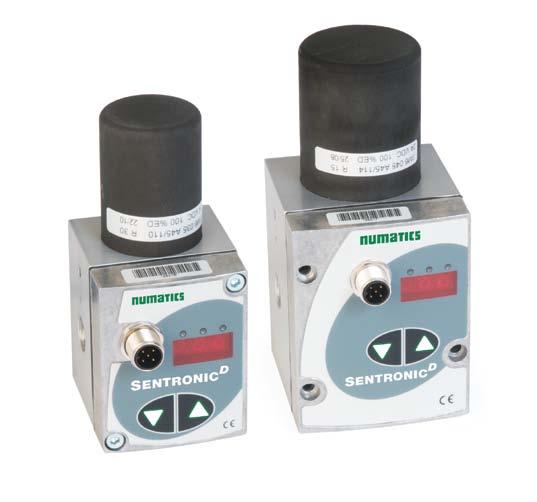
3 1. Description Sentronic D is a new generation of electronic pressure regulators designed on the basis of an enhanced digital control. Sentronic D stands for: Digital communication and control Display (incorporated) Direct operated valve Dynamic behaviour (high speed) Digital control offers many advantages during installation and start-up of the Sentronic D valve and extended possibilities to adapt it to various applications. The four following standard versions are available: With display and pushbuttons: Pressure display, manual pressure setting and diagnostic LEDs. Without display and pushbuttons: The economic solution. Nominal diameter DN mm: with a flow rate of 70 l/min (SRA). Nominal diameter DN mm: with a flow rate of 1300 l/min (SRA). Various pneumatic connections: integral connections, back panel connection and subbase mount. All pressure and exhaust ports are the same size, which allows for short response times when the pressure is increased or decreased. Digital pressure control in a closed loop: An internal pressure sensor compares the setpoint at the inlet to the outlet pressure. The outlet pressure is adjusted in real time. The control parameters can be changed with the additional software called DaS. The DaS program (Data Acquisition Software) ensures that all parameters used by the valve can be changed. This flexibility allows the valve to be adapted to the application and enables the optimization of its response time, overshoot and precision. After having set the optimum parameters you can save them in a project file for your personal use or send them to our Product Support for future production. 1.1 How to Order Nominal diameter 60 = DN mm 609 = DN mm Version (ports), body 0 = G 1/ (DN), G 1/ (DN ) 1 = G 1/ (DN ), G 3/ (DN ) 2 = Manifold version 1) G 1/ (DN ), G 1/ ( DN ) 6 = NPT 1/ (DN ), NPT 3/ (DN ) Pressure range Maximum pressure A = 0-50 psi B = psi C = psi 90 psi 10 psi 190 psi 1 = 0-10 bar 2 = 0-12 bar 3 = 0-3 bar = 0-1 bar 5 = 0-15 bar 6 = 0-6 bar 60 6 C Maximum pressure 13 bar 15 bar 6 bar bar 1 bar 9 bar Notes: 1) See Accessories section for required manifold sub-base 2) Feedback input is needed for dual loop units Options A00 = Dual loop control 211 = Oxygen clean Display 0 = without display 1 = with display Digital output 1 = Pressure switch output PNP ± 5 % Feedback 1 = Feedback output 0-10 V 2 = Feedback output 0-20 ma 3 = Feedback output - 20 ma = Feedback input Volt 2) 5 = Feedback input ma 2) 6 = Feedback input ma 2) Command signal 0 = 0-10 V 1 = 0-20 ma 2 = - 20 ma 3

4 1.2 Operating Elements Pressure Regulation (Hand) 1 Proportional solenoid coil 2.1 Pressure supply 2.2 Pressure outlet 2.3 Exhaust 3 Power supply, M12 connector Operator buttons 5 3-digit display of outlet pressure 6 Ground connection, M 7 Threaded mounting holes M/6 mm Mounting holes for s 9.1 Green LED OFF: Setpoint feedback ON: Setpoint = feedback Flashing: Overtemperature 9.2 Yellow LED OFF: Normal ON: operation Flashing: AUTOSAFE enabled 9.3 Red LED OFF: Normal ON: Low voltage Flashing: Overvoltage 10 Serial communication (PC connection) After an interruption in the power supply, press both arrow buttons located beneath the display during power up to switch to the manual mode. The operating mode is indicated by the letters H n d in the display. The "H n d" display disappears when the arrow buttons are released. Press the left arrow button or DOWN arrow to reduce the outlet pressure, press the right arrow button or UP arrow to increase the outlet pressure. The yellow LED is on permanently during manual mode. Exit this operating mode by pressing both arrow buttons simultaneously or by turning off the power supply for a short time. 1. Operating Modes Shut-off: If the command signal falls below 0.5 %, the coil current is switched off and the valve is fully exhausted. Overtemperature: If the temperature of the internal control electronics exceeds 100 C, the operating mode is switched to AUTOSAFE and the green LED starts to flash. Undervoltage / overvoltage: If the supply voltage is less than 20 V or more than 30 V, the coil current is switched off and the valve is fully exhausted. The red LED lights up constantly to indicate undervoltage or flashes to indicate overvoltage. Autosafe: If the coil current exceeds 1000 ma (DN) or 560 ma (DN) for more than 20 seconds, the output current is limited to max. 70% every seconds to prevent the valve from overheating. The yellow LED flashes.
5 2. Electrical Connection 5-pin M12 female connector (view on soldered side) Numatics 6 Wire Cable Color Code Control M12 connector Valve Brown Blue White Yellow +2V supply voltage Supply voltage GND Setpoint 0-10V (or 0-20 / -20mA) Setpoint GND (only for 6-wire cable) 250 Ohm at current setpoint Analog output: Black Only at current output: max. 500 ohm Feedback 0-10V (or 0-20 / -20mA) Digital output: Gray Inductive load PNP when setpoint is reached (setpoint=feedback) =200mA max./.w Shield Connector housing M connection on valve body 1) The valve must only be supplied with 2V DC at a tolerance of +15%/-10% and a max. ripple of 10% (no supply via diode bridge). Overvoltage or a ripple rate exceeding these tolerances can damage the electronics. 2) The max. current at the digital output is 200 ma/.w (PNP output). The output is protected against short circuit and overload. 3) If a relay (inductive load) is connected to the digital output, a freewheel diode or a varistor must be used. ) A shielded cable must be used for protection against interference and EMC. 5) The valve body must be grounded with the earthing terminal PE (dia. M) Connector Pin Out Command signal: View on soldered side of female connector PIN Description 1 +2 VDC Supply 2 Command Signal 3 +0 VDC Common (Supply) +0 VDC Common (Command Signal)* Analog output (feedback) 5 Digital output (pressure switch) Body EMC shield *A 6-wire cable with separate common for the command signal is used for cable lengths over 2 m to minimize the voltage drop for the command signal. 5
6 3. Analog Setpoint - Outlet Pressure Setpoint offset The pressure setpoint zero can be changed via the DaS program. Switch to "Custom" in the "Setpoint setting" section. The zero range is max. ±50 %. Max. outlet pressure PMR +50 % PMR SHUT-OFF 50 mv 0.1 ma.0 ma -50 % PMR Factory setting 0 5 V 0 10 ma 12 ma Offset adjustment 10 V 20 ma 20mA Max. Outlet Pressure PMR Max. Inlet Pressure 50 psi 90 psi 100 psi 10 psi 150 psi 190 psi 1 bar bar 3 bar 6 bar 6 bar 9 bar 10 bar 13 bar 12 bar 15 bar 15 bar 1 bar CAUTION: Outlet pressures above the maximum outlet pressure (PMR) are not controlled by the valve, i.e. the max. outlet pressure is limited to the PMR. In order to avoid damaging the sensor, the supply pressure must always be less than the maximum inlet pressure defined above (see table). Setpoint span The span of the output pressure can be changed via the DaS program. Switch to "Custom" in the "Setpoint setting" section. The span is between 10 and 100%. Max. outlet pressure (PMR) Max. outlet pressure 0.5 PMR SHUT-OFF 50 mv 0.1 ma.0 ma 00 0 Factory setting: 100 % 50 % setting Span adjustment 10 V 20 ma 20mA The span can be set to max. 100% of the maximum outlet pressure (PMR). It can only be decreased. 6
7 . Pneumatic Connection The air flow is from port 1 to port 2. Pressure outlet 2 Pressure supply 1 Exhaust 3 Inch screw connections (pipe threads) must be used. Each screw connections must be lined with a fitting synthetic sealing disc. Do not use Teflon sealing tape or hemp as they may get inside the valve and damage it. Use an appropriate silencer at port (3). The exhaust time may vary depending on the type of silencer used. The diameter of the pneumatic lines must be adjusted to the nominal diameter of the valve. The diameter of outlet line (2) must be larger or equal to that of inlet line (1). The supply pressure must always be less than the value given in the table in section 3 and must always be above the desired outlet pressure. 5. Factory Settings for a Standard Valve 0 psi outlet pressure at a setpoint of 0 V / 0 ma / ma. Span: 50 psi device: = 50 psi at 10 V / 20 ma 100 psi device: = 100 psi at 10 V / 20 ma 150 psi device: = 150 psi at 10 V / 20 ma Minimum hysteresis. 3 bar device: = 3 bar at 10 V / 20 ma 6 bar device: = 6 bar at 10 V / 20 ma 10 bar device: = 10 bar at 10 V / 20 ma The control parameters, setpoint offset, setpoint span and window size of the digital output (pressure switch) are factory-programmed. Parameter set: factory settings Offset: 0 % Span: 100 % Ramp: no ramp Shut-off: ON; the valve is exhausted at a command signal below 0.5% Controller structure: PID Proportional gain:.0 Integration time: 0.1 sec Derivation time: msec 7
8 6 Field-Programmable Settings Display/Pressure Readings The actual outlet pressure is displayed during normal operation. See "Parameters/Display" section. Other displays: Hnd indicates that the mode has been selected. SOF Internal error of pressure control. Replace valve or contact our Product Support. Err Internal overflow. AEr Autozero overflow. Contact our Product Support. Push Buttons To enter the mode, press and hold both pushbuttons simultaneously during power up. "Hnd" appears in the display. Use the UP button to increase the outlet pressure and the DOWN button to decrease it. The actual outlet pressure is displayed. Quick presses on the buttons allow you to make slight changes in the pressure rating. Longer presses allow you to make quick pressure changes. Press both pushbuttons simultaneously to exit the manual mode. 7. Technical Characteristics Construction Directly operated valve Body: Aluminium Internal parts: POM Seals: NBR (nitrile), FPM (fluoroelastomer) 7.1 Fluid Characteristics Assembly position: any; for optimum performance vertically with solenoid at the top. Air: filtered at 50 µm, free of condensate Connections: Hemp or Teflon tape must not be used. Electrical connection: Select a wire section that will give a voltage drop of less than 2 volts at 2A. Fluids: Air or neutral gas, filtered at 50 µm, free of condensate, lubricated or not Ports: 1/-1/-3/ NPT or GTap, see section 3 Max. Inlet Pressure: see section 3 Temperature / Fluid: 32 F - 10 F (0ºC - 60ºC) Temperature / Ambient: 32ºF - 122ºF (0 C - 50 C) Hystersis: <1% of span Linearity: <0.5% of span Repeatability: <0.5% of span Minimum Setpoint: 100mV (0.2 ma/.2ma) with shut-off function Minimum Outlet Pressure: <1% of span 7.2 Specifications Nominal diameter dn (mm) Supply voltage (stabilised)* Max. Power (W) Max. Current (ma) Insulation Class Degree of Protection Kv Nm 3 /h Flow l/min (SRA) Electrical Connection 2 V = +15%/-10% H IP V = +15%/-10% H IP * Residual ripple: 10 % Test conditions according to ISO 77: temperature: 20 C, relative inlet pressure: 6 bar, relative outlet pressure: 5 bar 5-pin female M12 connector 5-pin female M12 connector Command signal: V (100 kohm input resistance) ma / ma (250 Ohm input resistance) Feedback output: V (max. 10 ma), short-circuit protected ma / ma (max. 2 VDC) Digital output: pnp; open collector; max. 200 ma/.w, short-circuit protected HIGH (2 VDC) if feedback=setpoint LOW (open) if feedback setpoint Overvoltage: Shut-off at a voltage level higher than 30 volts (+10%). Low voltage: Shut-off at a voltage level lower than 19.5 volts (-10 %).
9 . Accessories 5 Pin 12mm FEMALE Straight Field Attachable Connectors Model Number PG 9 Cable Gland TC05F Pin 12mm FEMALE 90 DEGREE Field Attachable Connectors PG 9 Cable Gland TD05F Micro Female 5 Pole Straight 6 Wire 22 AWG, Shielded 3 Meter TC0503MMS000671Y 5 Meter TC0505MMS000671Y Micro Female 5 Pole 90 Degree 6 Wire 22 AWG Euro Color Code, Shielded 3 Meter TD0503MMS000671Y 5 Meter TD0505MMS000671Y Micro F/M Pole Straight 22 AWG Euro Color Code Unshielded Shielded 2 Meter - TC003MIETA Meter - TC003MMETA Meter - TC005MIETA Meter - TC005MMETA0000 Micro F 90 /M Straight 22 AWG Euro Color Code Unshielded Shielded 2 Meter - TD003MIETA Meter - TD003MMETA Meter - TD005MIETA Meter - TD005MMETA0000 Manifold Model Number Manifold for 60 (DN mm) with G3/; common supply and exhaust 1) Manifold for 609 (DN mm) with G1/2; common supply and exhaust 1) PC Software & Cable Connectors Model Number DaS Light: Data Acquisition Software for Sentronic D - basic parameters - free download at Numatics.com DaS Expert: Data Acquisition Software for Sentronic D - full parameters - CD-ROM RS 232 cable converter; 2m cable with 9-pin Sub-D (plug connector) RS 232 cable converter; 2m cable with 9-pin Sub-D (screw connector) ) Manifold ships with required hardware and gaskets for connecting manifolds together. 9. Maintenance and Care No special maintenance or care required. 9
10 SentronicD 10. Dimensions in inches (mm), Weight in lbs (kg) Dimensions: Inches (mm), Weight in lbs (kg) Inline version: DN Ø 1.3 (35) Weight: 1.23 (0.56) M hole for ground screw 0.79 (20) (*) 1.52 (3.5) 2.22 (56.3) 2.67 (67.) 1/, 1/ NPT or GTap.39 (111.5) 2.56 (65) 1.71 (3.55) 0.7 (12) Programming Interface 0.5 (21.5) 1.69 (3) 2.05 (52) 1.73 () 0.59 (15) (*) 0. (22.3) 2.13 (5) 1.16 (29.5) M12x1 1/, 1/ NPT or GTap 0.79 (20) 1.6 (7.15) Connector 0.3 (11) 0.71 (1) Mounting holes: M thread 0.53 (13.5) 1.1 (29) Inline version: DN Weight: 2.9 (1.13) Ø 1.77 (5) 5.1 (137.5) M hole for ground screw 0.20 (5) 1.10 (2) 2.20 (56) Programming interface 0.6 (16.3) 2.0 (61) 0.9 (25) 2.25 (57.15) Mounting holes: M thread 0.51 (13) 3.06 (77.) 0.9 (2) 0.9 (25) 1.91 (.5) 2.61 (66.3) 3.35 (5) 1.67 (2.3) 1/, 3/ NPT or GTap 1.09 (27.6) 2.5 (72.5) 1.57 (0) Connector 2.6 (67) 2.50 (63.55) 0.71 (1) 1/, 3/ NPT or GTap 0.79 (20) 1.57 (0) 2.60 (66) 10
11 Dimensions: Inches (mm), Weight in lbs (kg) Manifold version: DN Weight: 1.23 (0.56) 1.3 (35) M hole for ground screw 2.56 (65) 2.13 (5) 0.79 (20) 2.22 (56.3) 0.7 (12) 0.5 (21.5) 1.69 (3) 2.05 (52) Connector Programming interface 1.6 (7.15) 0.63 (16) 2.67 (67.) 1.52 (3.5).39 (111.5) 1.71 (3.55) 0.1 (.5) 2.3 (60.5) 0. (22.3) 2.07 (52.5) 1.5 (7) 1.16 (29.5) 0.7 (12) 1/ GTap 2.05 (52) Manifold: DN 1.61 (1) 0.3 (21) 2.17 (55) 0.31 () 0.79 (20) 3/ GTap 3/ GTap 1.26 (32) 2.2 (57) 0.2 (6) 1.2 (32.5) 1.3 (35) 0.55 (1) 2.12 (5) 1/ GTap 1/ GTap 3.7 (95) 0.5 (11.5) 3/ GTap 3/ GTap 1.69 (3) 3.9 (100) 1.93 (9) 11
12 3/ GTap Sentronic D Dimensions: Inches (mm), Weight in lbs (kg) Manifold version: DN Weight: 2.9 (1.13) 1.77 (5) M hole for ground screw Connector 5.1 (137.) 1/ GTap 2.5 (72.5) 2.6 (67) 2.50 (63.55) 0.71 (1) 2.61 (66.3) 0.20 (5) Programming 1.91 (.5) 1.10 (2) interface 2.25 (57.15) 2.20 (56) 3.06 (77.) 1.05 (26.6) 1.67 (2.3) 3.35 (5) 2.0 (61) 1.50 (3) 0.55 (1) 2.60 (66) Manifold: DN 2.01 (51) 1/ GTap 0.5 (11.5) 1.5 (39) 1.1 (6) 0.31 () 1.02 (26) 2.6 (6) 0.71 (1) 2.01 (51) 2.17 (55) 0.3 (21) 1/2 GTap 1.3(35) 2.6 (6) 0.20 (5).53 (115).72 (120) 1/2 GTap 1/2 GTap 1/2 GTap 2.0 (61) 12
 11-20-1700 F: (55) 11-195-3970 P: 2-596-3200 F: 2-596-3201 Sentronic D Rev 05/12 Numatics Inc.")
13 World Class Supplier of Pneumatic Components World Headquarters USA Numatics, Incorporated 620 Dylan Drive Novi, Michigan 377 Canada Numatics, Ltd P: F: Mexico Numatics de Mexico S.A. de C.V. P: F: Brazil Ascoval Ind.e Comercio Ltda P: (55) F: (55) P: F: Sentronic D Rev 05/12 Numatics Inc Numatics, Inc. Tel (2) insidesales@numatics.com Numatics is registered in the United States and elsewhere
Digital Pressure Regulator Sentronic PLUS Series 614
 Digital Pressure Regulator Sentronic PLUS Series 14 Installation manual IM149-/R01 CONTENTS 1. Description... 1.1 Catalogue number... 1. Operating elements...4 1. Operating modes...4. Electrical connection...5.
Sentronic D 608 Series and 609 Series
 Sentronic D 608 Series and 609 Series Proportional Technology www.asco.com PRESSURE CONTROL: 608/609 SERIES SENTRONIC D Sentronic D Sentronic D is a digitally operated pressure regulator valve. Sentronic
Sentronic LP Digital Electronic Pressure Regulator. 617 Series with Display and Controls Installation Manual
 Sentronic LP Digital Electronic Pressure Regulator Series with Display and Controls Installation Manual Table of Contents Sentronic LP Description 2 How To Order 2 Operating Elements 3 Manual Pressure
Sentronic LP IO-Link CLASS A 617 Series. 617 Series IO-Link CLASS A with Display and Controls Installation Manual
 Sentronic LP IO-Link CLASS A Series Series IO-Link CLASS A with Display and Controls Installation Manual Table of Contents Sentronic LP Description 2 How To Order 2 Operating Elements 3 Manual Pressure
Sentronic LP 617 Series
 Sentronic LP 617 Series Proportional Technology www.asco.com PRESSURE CONTROL: 617 SERIES SENTRONIC LP Sentronic LP The Sentronic LP is a highly efficient and cost-effective option for your pressure regulation
Servotronic Digital 615 Series
 Servotronic Digital 615 Series Proportional Technology www.asco.com PRESSURE CONTROL: 615 SERIES SERVOTRONIC Digital Servotronic Digital Greater versatility in automated production processes: Due to electronics,
PROPORTIONAL VALVES Sentronic D - G 1/8 to G 3/8 tapped body or G 1/8 - G 1/4 subbase mounted body with digital pressure control
 PROPORTIONAL VALVES Sentronic D - G 1/8 to G 3/8 tapped body or G 1/8 - G 1/4 subbase mounted body with digital pressure control 3 ports Series 608 609 FEATURES Sentronic D is a highly dynamical 3-way
Sentronic PLUS 614 Series
 Sentronic PLUS 64 Series Proportional Technology www.asco.com PRESSURE CONTROL: 64 SERIES SENTRONIC PLUS Sentronic PLUS Sentronic PLUS is a digitally operated pressure regulator valve. This valve accurately
SentronicPLUS IO-Link CLASS A Electronic Pressure Regulator. Installation Manual
 SentronicPLUS IO-Link CLASS A Electronic Pressure Regulator Installation Manual Sentronic PLUS ASCO NUMATICS Sentronic PLUS Electronic Pressure Regulator Sentronic PLUS is a 3-way proportional valve with
Proportional Technology Precise Control of Pressure and Flow
 Precise Control of Pressure and Flow www.numatics.com Numatics, Inc. is a leading manufacturer of pneumatic products and motion control products. Our broad spectrum of standard, custom developed products
PROPORTIONAL VALVES. G1/4, G3/8 and G1/2 tapped body or subbase mounted body with digital pressure control
 PROPORTIONAL VALVES Sentronic LP G1/4, G3/8 and G1/2 tapped body or subbase mounted body with digital pressure control 3 ports Series 617 FEATURES Sentronic LP stands for: Low power consumption (3,8 W)
Proportional Technology. Precise Control of Pressure and Flow
 Proportional Technology Precise Control of Pressure and Flow Table of Contents Introduction to Control Technology Glossary of Terms 2 Control Systems/Control Methods 4 Types of Contollers 5 Applications
Proportional Technology Precise Control of Pressure and Flow
 Precise Control of Pressure and Flow w w w. n u m a t i c s. c o m Numatics, Inc. is a leading manufacturer of pneumatic products and motion control products. Our broad spectrum of standard, custom developed
Servotronic Digital 615 Series
 Servotronic Digital 615 Series Proportional Technology Архангельск (818)6-90-7 Астана (717)77-1 Астрахань (851)99-46-04 Барнаул (85)7-04-60 Белгород (47)40--64 Брянск (48)59-0-5 Владивосток (4)49-8-1 Волгоград
Sentronic LP IO-Link CLASS A 617 Series. Proportional Technology
 Sentronic LP IO-Link CLASS A 617 Series Proportional Technology PROPORTIONAL PRESSURE CONTROL: 617 SERIES SENTRONIC LP IO-LINK VERSION ASCO NUMATICS Sentronic LP The Sentronic LP is a highly efficient
E22 Proportional Technology
 E22 Proportional www.numatics.com Pressure Control: E22 Proportional E22 Series Unlike SENTRONIC valves, E-Series valves operate with pulsed pilot valves which change the pressure in a control chamber.
PRM7-04. Functional Description HA /2012. Proportional Directional Control Valves. Replaces HA /2009
 Proportional Directional Control Valves PRM7-6/ Size D () bar (6 PSI) L/min (. GPM ) Replaces /9 Digital control Compact design Operated by proportional solenoids High sensitivity and slight hysteresis
WBG Series Wide Body Grippers
 WBG Series Wide Body Grippers www.numatics.com Table of Contents WBG Series Parallel Grippers Features and Benefits 3 How To Order 3 WBGS 60 Dimensions & Technical 4 WBGS 90 Dimensions & Technical 5 WBGL
PRM7-06. Functional Description HA /2006. Proportional Directional Control Valves. Replaces HA /2002
 Proportional Directional Control Valves PRM7-6 HA 59 /6 Size D (6)...6 PSI ( bar)...6 GPM ( L/min) Replaces HA 57 / Digital control Compact design Operated by proportional solenoids High sensitivity and
PRM7-06. Functional Description HA /2014. Proportional Directional Control Valves. Replaces HA /2013
 Proportional Directional Control Valves PRM7-6 / Size 6 (D ) bar (76 PSI) L/min (.6 GPM) Replaces HA 7 / Digital control Compact design Operated by proportional solenoids High sensitivity and slight hysteresis
WG Series Double Guided Wedge Grippers
 WG Series Grippers www.numatics.com Table of Contents WG Series Parallel Gripper Features & Benefits 3 How To Order 4 WGS50 Dimensions 5 WGS50 Technical Specifications 5 WGL50 & WGS90 Dimensions 6 WGL50
Pilot-Operated Proportional DC Valve Series D*1FH
 Characteristics The pilot-operated proportional DC valves series of the D*1FH series are high-performance valves with electronic spool position feedback. These valves are available in sizes NG10 to NG2
PBS Series Power Block Slide
 PBS Series Power Block Slide www.numatics.com Table of Contents PBS Series Features and Benefits 3 How To Order 4 Technical Specifications 4 Dimensions 5 Quick Disconnect Cables 6 Switch Information 6-7
AG Series Angular Grippers
 AG Series Angular Grippers www.numatics.com Table of Contents AG Series Angular Grippers Features and Benefits 3 How to Order 4 Dimensions 5 Specifications and Load Ratings 6 Sensing Part Numbers 7 Quick
Operating Instructions. Angle Seat Control Valve. Type 7020
 Operating Instructions Angle Seat Control Valve Type 7020 With: Digital Positioner Type 8048 Electro-pneumatic Positioner Type 8047 Pneumatic Positioner Type 8047 Version: 02/2006 Manual-7020e.doc Art.-No:
Instruction Manual. ThinkTop D30 ESE02248-EN Patented Sensor System Registered Design Registered Trademark. Original manual _1
 Instruction Manual ThinkTop D30 2064-0000_1 Patented Sensor System Registered Design Registered Trademark ESE02248-EN3 2014-12 Original manual Table of contents The information herein is correct at the
Nu Lock Units NFPA and ISO/VDMA Nu Locks
 Nu Lock Units NFPA and ISO/VDMA Nu Locks www.numatics.com Table of Contents NuLock Series Features and Benefits 3 How to Order 3 Dimensions 4 Cylinder and Lock Information 5 Installation Information 5
Precision Regulators.
 Precision www.numatics.com Table of Contents Features and Benefits 3 Electropneumatic Transducer 4-5 Economy Miniature Electropneumatic Transducer 6-7 Miniature Electropneumatic Transducer 8-9 Precision
VED05MJ - PROPORTIONAL DIRECTIONAL CONTROL VALVES WITH OBE & POSITION FEEDBACK
 CONTINENTAL HYDRAULICS VED05MJ PROPORTIONAL DIRECTIONAL CONTROL VALVES WITH OBE & POSITION FEEDBACK VED05MJ - PROPORTIONAL DIRECTIONAL CONTROL VALVES WITH OBE & POSITION FEEDBACK 5505 WEST 123RD STREET
Proportional directional valve, direct operated, with pq functionality
 Proportional directional valve, direct operated, with pq functionality RE 2914/3.13 Replaces: 12.12 1/18 Type STW 19, type STW 196 STW 19: Size 6 Component series 2X STW 196: Size 1 Component series 1X
Operating Instructions. Pneumatic Control Valve Low Temperature. Type Series GS3
 Operating Instructions Pneumatic Control Valve Low Temperature Type 8026 Series GS3 With: Digital Positioner Type 8048 Electro-pneumatic Positioner Type 8047 Pneumatic Positioner Type 8047 Version: 03/2006
VP23. 3-way proportional pressure control valve Directly-controlled seat valve with μp-driven pressure control G 1/4 to G 3/4 Nominal diameter 8/16
 VP ll-digital control electronics Variable pressure control, external pressure control upon request Optional: serial interfacing with VP-Tool program Optional actuation via fieldbus (separate data sheet
Publ. 3-EN 2950-A. DENISON HYDRAULICS Pressure Relief Valve R6V
 Publ. 3-EN 2950-A DENISON HYDRAULICS Pressure Relief Valve R6V FEATURES, SYMBOL FEATURES High Performance: R6V valves are designed for a maximum pressure of 350 bar and a flow capacity up to 650 l/min.
ISO/VDMA Series ISO 6431 and VDMA Cylinder Line
 ISO/VDMA Series ISO 6431 and VDMA 24562 Cylinder Line www.asco.com Table of Contents ISO/VDMA Series Features and Benefits 2 How to Order 3 Technical Information 4 Dimensions Tie-Rod Version 5 Mounting
ISO/VDMA Series ISO 6431 and VDMA Cylinder Line ISO 6431 and VDMA Cylinder Line w w w. n u m a t i c s. c o m
 ISO/VDMA Series ISO 6431 and VDMA 24562 Line Cylinder Line ISO 6431 andcylinder VDMA 24562 w w w. n u m a t i c s. c o m Table of Contents ISO/VDMA Series Features and Benefits 3 How to Order 4 Technical
Proportional Pressure Relief Valves Series R4V and R6V (Onboard Electronics) General Description. Features.
 General Description. Features.") Catalog HY14-2/US Technical Information General Description Series R4V and R6V proportional pressure relief valves feature onboard electronics based on the functionality of the digital amplifier PCD. The
Catalog HY14-2/US Technical Information General Description Series R4V and R6V proportional pressure relief valves feature onboard electronics based on the functionality of the digital amplifier PCD. The
CONTINENTAL HYDRAULICS VED03MX
 CONTINENTAL HYDRAULICS VED03MX HIGH PERFORMANCE, SERVO-PROPORTIONAL DIRECTIONAL CONTROL VALVE 5505 WEST 123RD STREET SAVAGE, MN 55378-1299 / PH: 952.895.6400 / WWW.CONTINENTALHYDRAULICS.COM VED03MX HIGH
VP23, 3-way proportional pressure control valves Seat valve with μp-driven pressure control
 VP, -way proportional pressure control valves > > Port size: G/... G/ > > All-digital control electronics > > Variable pressure control > > Optional: serial interface with VP-Tool Software > > Optional
Electro-Pneumatic Devices Valves and Positioners. The Drive & Control Company
 Electro-Pneumatic Devices Valves and Positioners The Drive & Control Company Electro-Pneumatic Devices Dynamic precision from Rexroth Why choose Rexroth E/P s? Rexroth electro-pneumatic pressure control
Table of Contents. Proportional & Precision Regulator Instrumentation
 Table of Contents Proportional & Precision Regulator Instrumentation...3-27 Features and Benefits... 3 Electropneumatic Transducer...4-5 Economy Miniature Electropneumatic Transducer...6-7 Miniature Electropneumatic
VP23 3-way proportional pressure control valve Directly-controlled seat valve with µp-driven pressure control G 1/4... G 3/4
 -way proportional pressure control valve Directly-controlled seat valve with µp-driven pressure control G /... G / All-digital control electronics Variable pressure control Optional: serial interface with
Remote Process Actuation Control System AirLINE - Rockwell 1734 Point I/O System
 Remote Process Actuation Control System AirLINE - Rockwell 1734 Type 8644 can be combined with... Fully compatible with Rockwell 1734 Point I/O System Combination of Fieldbus, pilot valves and I/O modules
4/3-Proportional Solenoid Valve direct acting with integrated Electronics Subplate to ISO4401 P4WEE 10
 4/3-Proportional Solenoid Valve direct acting with integrated Electronics Subplate to ISO4401 P4WEE 10 SYMOL E a P T b FETURES High flow rate due to optimized casted housing Low hysteresis by super finish
Thermal hysteresis 0.5% max. of full scale (within compensated temperature range) 1% max. for ranges mbar mbar mbar
 1% max. for ranges mbar mbar mbar") Pressure Transmitter Type FM40466 General application Pressure transmitters are used to measure the relative (gauge) and absolute pressures in liquids or gases. The measuring device for the transmitter
Pressure Transmitter Type FM40466 General application Pressure transmitters are used to measure the relative (gauge) and absolute pressures in liquids or gases. The measuring device for the transmitter
MM1/MM2 INSTALLATION & MAINTENANCE INSTRUCTIONS
 MM1/MM2 INSTALLATION & MAINTENANCE INSTRUCTIONS DESCRIPTION / IDENTIFICATION The MM series proportional control valves utilize ProportionAir's unique closed loop control technology for superior control
DC-PMM/24V Power Management Modul für Positionier-Motor POSMO A Power Management Module for Positioning Motor POSMO A
 s DC-PMM/24V Power Management Modul für Positionier-Motor POSMO A Power Management Module for Positioning Motor POSMO A Best. Nr. / Order No.: 9AL2137-1AA00-1AA0 Betriebsanleitung Operating Instructions
Data Sheet. I/P and E/P converters. RS stock numbers ,
 Data Pack G Issued March 997 3-4998 Data Sheet I/P and E/P converters RS stock numbers 79-47, 79-48 Standard (electro-mechanical) Construction Housing Zinc diecastings, passivated and black epoxy paint,
Electronic Ballast EVG 2000-T
 Electronic Ballast EVG 2000-T Operating Manual Table of contents 1 Description 1.1 Advantages of this ballast... 3 1.2 Functional principle... 3 1.3 Energization... 4 1.4 Visualization... 5 1.5 Indications
TZIM. Electropneumatic Analog Positioner 10/ EN
 TZIM Electropneumatic Analog Positioner EP001XA.tif Q Convenient, simple design Q Easy to handle Q User-friendly operation, easy to understand Q Reliable concept, I/P conversion through the 500,000 times
SKF Electro-pneumatic Barrel Pump EPB-Pump-ECO (Original operating and maintenance instructions according to EU Directive 2006/42/EC)
") SKF Electro-pneumatic Barrel Pump EPB-Pump-ECO (Original operating and maintenance instructions according to EU Directive 2006/42/EC) TABLE OF CONTENTS 1 EC Declaration of incorporation...1 2 General description...2
SKF Electro-pneumatic Barrel Pump EPB-Pump-ECO (Original operating and maintenance instructions according to EU Directive 2006/42/EC) TABLE OF CONTENTS 1 EC Declaration of incorporation...1 2 General description...2
Proportional Pressure Relief Valve Series RE*T
 Characteristics The pressure relief valve series RE*T have a proportional solenoid operated pilot stage with integrated electronics and a cartridge main stage. Features Pilot-operated pressure relief valve
JUMO MIDAS Pressure transmitter
 Phone: +44 19 635533 Fax: +44 19 6356 Data Sheet 401001 Page 1/5 JUMO MIDAS Pressure transmitter Brief description Pressure transmitters are used for measuring the relative (gauge) pressure in liquids
JUMO DELOS SI. Precision pressure transmitter with switching contacts and display. Application. Brief description. Key features.
 Data sheet 405052 Page 1/10 JUMO DELOS SI Precision pressure transmitter with switching contacts and display Application Food & pharma CIP/SIP systems Machine and system construction Air conditioning and
Remote Process Actuation Control System AirLINE WAGO Remote I/Os and Fieldbusses
 Remote Process Actuation Control System AirLINE WAGO Remote I/Os and Fieldbusses Type 8644 can be combined with... Fully compatible with WAGO I/O Combination of Fieldbus, pilot valves and I/O modules High
Solid State Electronic Pressure Switch with Integral LED Display Model PSD-10
 Solid State Electronic Pressure Switch with Integral LED Display Model PSD-10 Electronic Pressure Measurement WIKA Datasheet PSD-10 Applications Hydraulics and pneumatics Filter monitoring Pump control
ITVX Series. Stepless control of air pressure proportional to an electrical signal. Supply pressure: 5.0 MPa
 5.0 MPa Maximum Supply Pressure High Pressure Electro-Pneumatic Regulator X Series This product is only for blowing gas. This product does not have sufficient pressure control for other applications (driving,
REMOTE MOUNT SOLENOID DRIVER (0-5 VDC/0-20 ma/10k Potentiometer Input)
") REMOTE MOUNT SOLENOID DRIVER (0-5 VDC/0-20 ma/10k Potentiometer Input) Part No.: PCB Board - RSD-PCB-5V-x DIN Rail Mount RSD-DR-5V-x Packaged Driver (board installed in metal box) Available with no cable
REMOTE MOUNT SOLENOID DRIVER (0-5 VDC/0-20 ma/10k Potentiometer Input) Part No.: PCB Board - RSD-PCB-5V-x DIN Rail Mount RSD-DR-5V-x Packaged Driver (board installed in metal box) Available with no cable
Series PD directly operated solenoid valves
 > Series PD solenoid valves CATALOGUE > Release 8.7 Series PD directly operated solenoid valves New /-way Normally Closed (NC) Note: all Series PD /-way solenoid valves are basically in DC. To operate
Proportional directional valve, pilot-operated, with integrated electronics (OBE)
") Proportional directional valve, pilot-operated, with integrated electronics (OBE) Type WFCE RE 943 Edition: 7- Replaces: 6- Size 6 5 Component series X Maximum operating pressure 4 bar Maximum flow 5 l/min
Proportional directional valve, pilot-operated, with integrated electronics (OBE) Type WFCE RE 943 Edition: 7- Replaces: 6- Size 6 5 Component series X Maximum operating pressure 4 bar Maximum flow 5 l/min
2-way proportional throttle valve for block installation
 -way proportional throttle valve for block installation RE 90/07.05 Replaces: 03.00 / Types FE; FEE Size 6 Component series X Maximum operating pressure 35 bar Maximum flow 90 L/min bei p = 0 bar H4538
4/3 proportional directional control valve, without position control, with on-board electronics (OBE)
") 4/3 proportional directional control valve, without position control, with on-board electronics (OBE) Type 4WRBAE..E.. /..W.. Nominal size (NG) 6, 10 Unit series 2X Maximum working pressure P, A, B 315
4/3 proportional directional control valve, without position control, with on-board electronics (OBE) Type 4WRBAE..E.. /..W.. Nominal size (NG) 6, 10 Unit series 2X Maximum working pressure P, A, B 315
A Member of the. Integrated Metering Technologies
 I n s t a l l a t i o n M a n u a l A Member of the Integrated Metering Technologies 1.0 General and Safety Do not install, operate or maintain this flow meter without reading, understanding and followingthe
VED05MG CONTINENTAL HYDRAULICS PROPORTIONAL DIRECTIONAL CONTROL VALVES WITH OBE VED05MG - PROPORTIONAL DIRECTIONAL CONTROL VALVES WITH OBE
 CONTINENTAL HYDRAULICS VED05MG PROPORTIONAL DIRECTIONAL CONTROL VALVES WITH OBE 5505 WEST 123RD STREET SAVAGE, MN 55378-1299 / PH: 952.895.6400 / FAX: 952.895.6444 / WWW.CONTINENTALHYDRAULICS.COM POWERFUL
Type Operating Instructions. Bedienungsanleitung Manuel utilisateur
 Water flow rate transmitter Wasser-Durchfluss-Transmitter Transmetteur de débit d eau Operating Instructions Bedienungsanleitung Manuel utilisateur We reserve the right to make technical changes without
Type 2000 Transducer Product Instructions
 Type 2000 Transducer Product Instructions The Type 2000 is an electro-pneumatic device that regulates an unregulated supply pressure down to an electronically-controlled output pressure. There are two
Control block VOFA with safety function
 Key features Innovative Versatile Reliable Easy to assemble Can be used for safe reversing of a hazardous movement (5/2-way solenoid valve) Can be used for safe venting (3/2-way solenoid valve function,
Remote Process Actuation Control System AirLINE - Siemens ET 200S
 Remote Process Actuation Control System AirLINE - Siemens ET 200S Type 8644 can be combined with... Fully compatible with Siemens ET 200S Combination of Fieldbus, pilot valves and I/O modules High flexibility
MWR Reamer 08/01/2010
 MWR Reamer 08/01/2010 Operating Instructions and Spare Parts List Torch Nozzle Cleaning Device for Robotic Mig Welding System Registration Purchaser: Address; City State Zip Phone: Email: Contact: Purchased
XMLRM01G1P25 Pressure sensors XMLR -1 bar - G 1/4-24VDC ma - PNP - M12
 Characteristics Pressure sensors XMLR -1 bar - G 1/4-24VDC - 4..20 ma - PNP - M12 Complementary Current consumption Electrical connection Type of output signal Analogue output function Discrete output
CONNECTOR AMPLIFIER FOR PROPORTIONAL VALVES (0-10VDC Input Version)
") TECHNICAL DATASHEET #TD1101AX CONNECTOR AMPLIFIER FOR PROPORTIONAL VALVES (0-10VDC Input Version) Part No.: CAPV-H-10V-x complete with cable CAPV-S7C-yM Where: x = current output (2A, 1.2A or 600MA) y
TECHNICAL DATASHEET #TD1101AX CONNECTOR AMPLIFIER FOR PROPORTIONAL VALVES (0-10VDC Input Version) Part No.: CAPV-H-10V-x complete with cable CAPV-S7C-yM Where: x = current output (2A, 1.2A or 600MA) y
Proportional pressure regulators VPPX
 Features LED indicators Plug socket with cable Venting at both ends Manifold block Sub-base valve Angle bracket Individual valve H-rail mounting repositionable by 180 Compressed air supply at both ends
Mountable with O-ring seal Urea level ±0.5% Accuracy Urea pressure ±2.0 Total Error Band Air Brakes Corrosive fluid measurement for E&V applications
 Mountable with O-ring seal Stainless Steel wetted surfaces Amplified ASIC calibrated Absolute, sealed gage Cable option Analog output DESCRIPTION The U86B is a small profile, media compatible, piezoresistive
Electropneumatic Converters i/p Converters Type 6111 Mounting and Operating Instructions EB 6111 EN
 Electropneumatic Converters i/p Converters Type 6111 Fig. 1 Type 6111 in standard version Fig. Type 6111 mounted on a supply air manifold Fig. 3 Type 6111 in field enclosure Mounting and Operating Instructions
USERS MANUAL MCD REMOTE OPERATOR
 USERS MANUAL MCD REMOTE OPERATOR Order Code: 175G9004, 175G3061 Contents Contents Introduction...2 Important User Information...2 General Description...2 Symbols Used in this Manual...2 Installation...3
Temposonics. G-Series Analog Redundant. Magnetostrictive Position Sensors. Redundancy for enhanced safety
 Temposonics Magnetostrictive Position Sensors m SENSORS G-Series Redundant Temposonics GT2 and GT3 Measuring length 25-1500 mm Redundancy for enhanced safety Up to 3 totally separated, independent measuring
Series PD directly operated solenoid valves
 > Series PD solenoid valves CATALOGUE > Release 8.8 Series PD directly operated solenoid valves /-way - Normally Closed (NC) Please note that all Series PD solenoid valves are supplied with direct current
Flowmeter Ultrasonic Flow Metering / Dosing Device. Operating Manual
 Flowmeter Ultrasonic Flow Metering / Dosing Device Operating Manual Read the user's manual carefully before starting to use the unit or software. Producer reserves the right to implement changes without
Operating Instructions Vaccon VDS-1000 Solid State Combination Vacuum Switch/Sensor w/ Digital Display
 Operating Instructions Vaccon VDS-1000 Solid State Combination Vacuum Switch/Sensor w/ Digital Display Installation The VDS-1000 combines either two (2) low voltage, high side or low side, switched outputs
VED*MJ PILOT OPERATED DIRECTIONAL CONTROL VALVES WITH OBE & FEEDBACK
 CONTINENTAL HYDRAULICS VED*MJ PILOT OPERATED DIRECTIONAL CONTROL VALVES WITH OBE & FEEDBACK 5505 WEST 123RD STREET SAVAGE, MN 55378-1299 / PH: 952.895.6400 / WWW.CONTINENTALHYDRAULICS.COM DURABLE VED*MJ
OEM Pressure Transmitters
 OEM Pressure Transmitters Type ECO-1 Applications Hydraulics and pneumatics Mechanical engineering General industrial applications Special Features Pressure ranges from 0-15psi to 0...15,000psi 4-20 ma
SBM TECHNOLOGY PET Blow Valve Block
 Advanced high pressure seal technology Robust, compact & lightweight design Proven & reliable technology Maintenance & service friendly High flow rate exhaust function Minimal dead space volume (< 35ml)
NRL Series Rod Lock.
 Series Rod Lock www.numatics.com Numatics, Inc. is a leading manufacturer of pneumatic products and motion control products. Our broad spectrum of standard, custom developed products and application components
29 158/ Proportional Pressure Relief Valve Models DBE and ZDBE, Series 1X. Ordering code DBE 6 1X G24 1/ PSI (315 bar)
") RA 29 58/6.98 Proportional Pressure Relief Valve Models DBE and ZDBE, Series X Size 6 (R 3)... 46 PSI (35 bar)... 8 GPM (3 L/min) RA 29 58/6.98 Replaces: 5.94 Valve for limiting system pressure Operation
RA 29 58/6.98 Proportional Pressure Relief Valve Models DBE and ZDBE, Series X Size 6 (R 3)... 46 PSI (35 bar)... 8 GPM (3 L/min) RA 29 58/6.98 Replaces: 5.94 Valve for limiting system pressure Operation
Proportional pressure reducing valve, pilot operated, with on-board electronics (OBE) and position feedback
 and position feedback") Proportional pressure reducing valve, pilot operated, with on-board electronics (OBE) and position feedback Type DREBE6X Nominal size (NG) 6 Unit series 1X Maximum working pressure P 315 bar, T 250 bar
Proportional pressure reducing valve, pilot operated, with on-board electronics (OBE) and position feedback Type DREBE6X Nominal size (NG) 6 Unit series 1X Maximum working pressure P 315 bar, T 250 bar
Operating Instruction for Flowmonitor. Model: DF-WM
 Operating Instruction for Flowmonitor Model: DF-WM 1. Contents 1. Contents... 2 2. Note... 3 3. Instrument Inspection... 3 4. Regulation Use... 4 5. Operating Principle... 5 6. Mechanical Connection...
MPV1 INSTALLATION & MAINTENANCE INSTRUCTIONS
 MPV1 INSTALLATION & MAINTENANCE INSTRUCTIONS DESCRIPTION / IDENTIFICATION The MPV1 series valve uses Proportion- Air closed loop technology for pressure control. It gives an output pressure proportional
MPV1 INSTALLATION & MAINTENANCE INSTRUCTIONS
 MPV1 INSTALLATION & MAINTENANCE INSTRUCTIONS DESCRIPTION / IDENTIFICATION The MPV1 series valve uses Proportion- Air closed loop technology for pressure control. It gives an output pressure proportional
VED*MJ - PILOTED PROPORTIONAL DIRECTION CONTROL VALVES WITH OBE & FEEDBACK
 CONTINENTAL HYDRAULICS VED*MJ PILOTED PROPORTIONAL DIRECTION CONTROL VALVES WITH OBE & FEEDBACK 5505 WEST 123RD STREET SAVAGE, MN 55378-1299 / PH: 952.895.6400 / WWW.CONTINENTALHYDRAULICS.COM VED*MJ PILOTED
2012 Series Solenoid Pilot Actuated Valves
 Series Solenoid Pilot Actuated Valves www.numatics.com Table of Contents 202 Series Terminal Strip, Sub-D, and Round Connector Options-Exploded View 3 Technical and Operating Data 4 How to Order 5 Individual
HBLT-C1 Controller. Instruction Manual. For pump control of levels in industrial refrigeration systems
 Instruction Manual HBLT-C1 Controller For pump control of levels in industrial refrigeration systems Instruction manual HBLT-C1 Controller (006-UK) 1 / 14 Table of Contents Safety Instructions... 3 Introduction...
20 to 150 mm 2-Way Automatic Flow Balancing Control Ball Valves
 VFB30 Series Issue Date February 1, 2016 20 to 150 mm 2-Way Automatic Flow Balancing Control Ball Valves Low Torque Facilitates the use of smaller, less expensive directmount rotary-motion actuators Extends
Modular pneumatic valve unit
 Modular pneumatic valve unit Compact design Modular configuration High flexibility Type 8640 can be combined with Simple exchange of valves (with option P-shut-off - also possible during operation) Type
CONTROLS. Bray Pneumatic Actuators & Accessories. Technical Manual. A Division of BRAY INTERNATIONAL, Inc.
 CONTROLS A Division of BRAY INTERNATIONAL, Inc. Bray Pneumatic Actuators & Accessories Technical Manual TM-056 Pneumatic Actuator - 08//00 Bray Pneumatic Actuators & Accessories Technical Manual - Table
EQ Series OEM Aluminum NFPA Interchangeable Cylinder Line
 Series OEM Aluminum NFPA Interchangeable Cylinder Line www.numatics.com Table of Contents EQ Series Features and Benefits 3 Standard Mounts 4 How to Order 5 Rod Ends 6 Dimensions 7 How to Order - EQ Series
MF /MS Series
 MF41-6153/MS41-6153 Series 24 Vac, Three-position/Modulating Non-spring Return Rotary Electronic Damper SmartX Actuators General Instructions Description The direct-coupled, 24 Vac, non-spring return electronic
JUMO MIDAS S05 Pressure transmitter Type
 Data Sheet 40.00 Page /8 JUMO MIDAS S05 Pressure transmitter Type 4000 Brief description The JUMO MIDAS S05 pressure transmitter is available with both relative pressure and absolute pressure measurement
+ = Angle-seat Valve System for continuous control. Type 8802/2300 electro-pneumatically operated angle-seat valve
 Angle-seat Valve System for continuous control Type 8802/2300 electro-pneumatically operated angle-seat valve + = TWO YEAR WARRANTY on this valve system Burkert 8802 continuous control valve + = 2300 series
SERIES PRE PROPORTIONAL PRESSURE REGULATOR WITH COILVISION TECHNOLOGY
 SERIES PRE PROPORTIONAL PRESSURE REGULATOR WITH COILVISION TECHNOLOGY 4.0 READY SERIES PRE PRESSURE UNDER CONTROL WITH DIAGNOSIS THROUGH THE CLOUD NFC WIRELESS MICRO USB The Series PRE proportional pressure
2-PHASE STEPPING MOTOR DRIVER FE Z5 DISPENSE
 2-PHASE STEPPING MOTOR DRIVER FE Z5 DISPENSE For Diaphragm Dosing Pumps FEM 1.02_.55 / FEM 1.09_.55 Controller board package, without pump: ID 160536 Operating and Installation Manual It is important to
VSD Series II Variable Speed Micro Drives
 VSD Series II Variable Speed Micro Drives Product Bulletin Code No. LIT-12011813 Issued March 26, 2013 Refer to the QuickLIT website for the most up-to-date version of this document. Johnson Controls VSD