Hot Food Deli Case MODELS WDCG, SSWG, CSWG Service Manual
|
|
|
- Dylan Walker
- 6 years ago
- Views:
Transcription

1 MODELS WDCG, SSWG, CSWG Service Manual
2 LIMITED ONE YEAR WARRANTY Warranty Information BKI (The Company ) warrants to the original purchaser/user, that at time of shipment from the Company factory, this equipment will be free from defect in materials and workmanship. Written notice of a claim under this Warranty must be given within ONE YEAR AND THREE MONTHS from date of shipment from the factory. Defective conditions caused by abnormal use or misuse, lack of maintenance, damage by third parties, alterations by unauthorized personnel, acts of God, failure to follow installation instructions or any other events beyond the control of the company will NOT be covered under Warranty. The obligation of the Company under this Warranty shall be limited to repairing or replacing (at the option of the company) any part which is defective in reasonable opinion of the Company. The user will have the responsibility and expense of removing and returning the defective part to the Company as well as the cost of reinstalling the replacement or repaired part. IN NO EVENT SHALL THE COMPANY BE LIABLE FOR LOSS OF USE, LOSS OF REVENUE OR LOSS OF PRODUCT OR PROFIT OR FOR INDIRECT OR CONSEQUENTIAL DAMAGES INCLUDING BUT NOT LIMITED TO, FOOD SPOILAGE OR PRODUCT LOSS. WARRANTY DOES NOT COVER GLASS BREAKAGE. THE ABOVE WARRANTY IS EXCLUSIVE AND ALL OTHER WARRANTIES, EXPRESS OR IMPLIED, ARE EXCLUDED INCLUDING THE IMPLIED WARRANTIES OF MERCHANTABILITY AND FITNESS FOR A PARTICULAR PURPOSE. THIS WARRANTY SHALL APPLY ONLY WITHIN THE CONTINENTAL UNITED STATES, ITS TERRITORIES, AND POSSESSIONS AND IN CANADA. LIMITED NINETY DAY LABOR WARRANTY All labor necessary to repair or replace factory defective parts will be performed, without charge, to the end user, by service personnel of a BKI Authorized Distributor during the first ninety days after the date of installation of the new equipment. Replacement parts: Any appliance replacement part, except lamps and fuses, which proves to be defective in material or workmanship within 90 days from date of original installation will be repaired or replaced without charge F.O.B. Factory, Simpsonville, S.C. or F.O.B. authorized distributor.
3 Table of Contents Table of Contents Table of Contents...1 Introduction...2 Safety Precautions...2 Operation...5 Controls and Indicators...5 Preheating...8 Temperature Adjustment...8 Operational Guidelines...8 Unit Shutdown...8 Installation...9 Unpacking and Handling...9 Floor Model...9 Pedestal Model...12 Counter Model...13 Wiring...14 Case Joining Trim...15 Case Divider Glass...16 Maintenance...17 Scheduled Maintenance...17 Well Numbering Convention...18 Troubleshooting...18 Control Service...20 Accessing Control Panel...20 Electrical Component Replacement...20 Glass Lift-Up Hardware Component Replacement...31 Replacement Parts...34 Control Panel...34 Pushbutton Switches and Terminal Block...35 Control Display...36 Heating Elements & Temperature Probes...37 Light & Heater Canopy...38 Glass Lift Hardware...39 Heated Shelf...40 Wiring Diagrams
4 Introduction Introduction Safety Precautions PLEASE READ THIS ENTIRE MANUAL BEFORE SERVICING THE UNIT. If you have any questions, contact the BKI Technical Service Department, toll free: Outside the U.S., call This unit is to be sealed to the floor after installation to conform to NSF requirements. (Dow Corning RTV #732 Multi purpose Sealant.) Always follow recommended safety precautions listed in this manual. Below is the safety alert symbol. When you see this symbol on your equipment, be alert to the potential for personal injury or property damage. Safety Signs and Messages The following Safety signs and messages are placed in this manual to provide instructions and identify specific areas where potential hazards exist and special precautions should be taken. Know and understand the meaning of these instructions, signs, and messages. Damage to the equipment, death or serious injury to you or other persons may result if these messages are not followed. This message indicates an imminently hazardous situation which, if not avoided, will result in death or serious injury. This message indicates a potentially hazardous situation, which, if not avoided, could result in death or serious injury. This message indicates a potentially hazardous situation, which, if not avoided, may result in minor or moderate injury. It may also be used to alert against unsafe practices. This message is used when special information, instructions or identification are required relating to procedures, equipment, tools, capacities and other special data. 2
5 Introduction Specific Precautions Equipotential Ground Plane When a high current flows through a conductor, differences in potential appear between the conductor and nearby metallic surfaces near the appliance. As a result, sparks may be produced between the appliance and surrounding metal surfaces. These sparks could cause serious injury, damage, or fire. BKI provides an Equipotential ground terminal for the connection of a bonding conductor after the installation of the appliance per lec This terminal is located on the inside of the Power Entry Supply box near the Earth connection and is marked with this symbol. Safe Work Practices Beware of High Voltage This equipment uses high voltage. Serious injury can occur if any untrained or unauthorized person installs, services, or repairs this equipment. Advise your customer to always use an Authorized Service agent to Service this Equipment Your Customer Should have an Operators Manual The operators manual is an important part of this equipment. Your customer should keep it near for easy access. If your customer needs a replacement operators manual, contact: BKI Technical Services Department P.O. Box Simpsonville, S.C Or call toll free: Outside the U.S., call
6 Introduction Safety Labels Must be Clean and in Good Condition Make sure all safety labels are in place, clean and in good condition. Replace any damaged or missing safety labels. If you need new safety labels, contact: BKI Technical Services Department P.O. Box Simpsonville, S.C Or call toll free: Outside the U.S., call
7 Operation Operation Controls and Indicators The deli case controls are shown in the figure below. The pushbutton switches turn the power supply to the case on and off. The touchscreen interface is used to operate the case and display temperatures. Hardware Controls Item # Description Function 1 Power OFF Switch Depressing the switch turns power OFF to the entire unit. 2 Power ON Switch Depressing the switch turns power ON to the entire unit. When the unit is ON the touchscreen controller is powered & the lights illuminate. 3 Main Power Isolator Light This light illuminates to indicate that power is being applied to the unit from the main power isolator (circuit breaker). 4 Analog Touchscreen Used for the operation of the unit and to measure & record product Interface 5 Controller RS-232 Interface temperatures. Allows user to download saved product temperatures to a laptop PC using the supplied software. 5
8 Operation Software Controls - Default Screen The Default Screen appears on the touchscreen during normal operation. The screen shows the menu button and a representative temperature. The representative temperature does not correspond to the internal temperature of the food products in the case. This temperature is only an indication that the case is operating properly and heating. When the unit is first powered up the representative temperature will be approximately room temperature. As the unit preheats the representative temperature will rise. The representative temperature will stabilize when the unit reaches operating temperature. Menu Button Default Screen Lower Right Lower Left The representative temperature should be approximately the same from day to day when the unit is in operation. A significant change in this temperature without changing any of the temperature settings of the unit may indicate a problem with the unit. A qualified BKI service representative should be contacted. Software Controls - Viewing Settings The current heater settings can be viewed by touching the Menu Button [M] on the Default Screen. The Menu Screen will then be displayed. To view the current settings for either Well Temp or Upper Heater touch the appropriate button on the Menu Screen. The View Setting Screen for the selected heaters will be displayed. To return to the Default Screen, touch the Exit Button [X]. If the controller is configured to control each well position independently the View Setting Screen as shown at right will be displayed. Use the left and right arrows to display the heater setting for the various well positions of the unit. The progress bar gives a visual representation of the well location for which the setting is being displayed. Exit Button Menu Screen Progress Bar The current heater setting is displayed on the right side of the screen. The setting is a numeric value between 1 and 10 where 10 is the hottest setting. If the controller is configured to control all of the well positions at the same setting, the progress bar will be solid and the left and right arrows will not be displayed. The setting shown will be for the heaters at all of the well positions. To return to the Menu Screen, touch the Menu Button [M]. To return to the Default Screen, touch the Exit Button [X]. Current Setting View Setting Screen Touching [Set Clock] on the Menu Screen will display the time and date. To return to the Menu Screen, touch the Menu Button [M]. To return to the Default Screen, touch the Exit Button [X]. 6
9 Operation Software Controls - Programming the Controller Menu Button There is a unique set of touches to enter the programming mode. This prevents the case settings from being inadvertently changed. Enter the programming mode from the Default Screen by touching the lower left of the touchscreen, then the lower right and then the Menu Button [M] in that order. The Menu Screen will then be displayed. To edit the current settings for either Well Temp or Upper Heater touch the appropriate button on the Menu Screen. The Edit Setting Screen for the selected heaters will be displayed. Default Screen Lower Right Lower Left To return to the Default Screen, touch the Exit Button [X]. If the controller is configured to control each well position independently the Edit Setting Screen as shown at right will be displayed. Use the left and right arrows to display the heater setting for the various well positions of the unit. The progress bar gives a visual representation of the well location for which the setting is being displayed. M Well Heater 1 X The current heater setting is displayed on the right side of the screen. Use the up and down arrows to edit the heater setting. The setting is a numeric value between 1 and 10 where 10 is the hottest setting. Edit Settings Screen If the controller is configured to control all of the well positions at the same setting, the progress bar will be solid and the left and right arrows will not be displayed. Use the up and down arrows to edit the heater setting for all of the well positions. To return to the Menu Screen, touch the Menu Button [M]. To return to the Default Screen, touch the Exit Button [X]. To edit the controller time and date settings touch [Set Clock] on the Menu Screen while in the program mode. The time and date will need to be reset if the power supply to the case has been disconnected. Use the left and right arrows to move the cursor under the value to be edited. Use the up and down arrows to edit the value. Continue until the current date and time is displayed. To return to the Menu Screen, touch the Menu Button [M]. To return to the Default Screen, touch the Exit Button [X]. 7
10 Operation Preheating You should allow the equipment to preheat at the programmed temperature settings for a minimum of 30 minutes before loading it with product. For initial start up, program the controller for each well and upper heater to a setting of 5. Check Federal and State Health and Sanitation Regulations for internal temperature required for holding cooked foods for sale. Maintaining these temperatures often tend to allow continued cooking of certain products. Therefore, smaller amounts of bulk foods should be displayed at non-peak periods and the warmer refilled as needed. All meats and vegetables should be preheated to 160 F (70 C). before being placed in the case. A screen liner can be used in the bottom of the display pans that are used for holding meats. This will keep meats from sticking to the bottom of the pans. Temperature Adjustment After placing the product into the equipment, it may be necessary to adjust the programmed settings in order to maintain the proper internal temperature for the product on display. The optional built-in product temperature probe or a portable meat thermometer should be used to read the internal temperature of each product. The programmed settings should be set to the lowest possible number that will maintain the proper product temperature. Operational Guidelines Keep the optional built-in product temperature probe or a portable meat thermometer on hand. Check the food temperatures hourly. Rotate the food products. Foods loaded in first should be served first as much as is practical. Foods held for long periods of time are more difficult to maintain at proper temperature. Also, freshness and product quality diminish if foods are held too long. Most areas of the country have sanitation regulations governing how long foods can be held. Make certain to check with your local authorities. Unit Shutdown Remove all food pans holding the food product from the equipment. Depress the OFF pushbutton switch to turn the power to the heaters and lights off. After the temperature has cooled below 120 F (50 C), remove any residue from the wells and clean the equipment thoroughly. 8
11 Installation Installation Unpacking and Handling The company taking delivery of this equipment is responsible for filling all freight claims with the delivering truck line. Inspect all cartons and crates for damage as soon as they arrive. If damage to cartons or crates is found, or if a shortage is found, note this on the bill of lading (all copies) prior to signing. If damage is found when the equipment is opened, immediately call the delivering truck line and follow up the call with a written report indicating concealed damage to your shipment. Ask for an immediate inspection of your concealed damage item. Packaging material MUST be retained to show the inspector from the truck line. Do not walk on top of deli cases or damage to the cases and serious personal injury could occur. The cases are not structurally designed to support excessive external loading such as the weight of a person. Do not place heavy objects on the deli cases. Move the deli case as close as possible to its permanent location before moving the case off of the shipping pallet. Shipping braces are installed on each end of the deli case. Leave these braces in place while moving and leveling the deli case. Make certain there are no separately packed accessories before discarding packaging. During shipment, the lubricant in the gas springs may have settled. This can cause the glass not to remain open in the raised position. To avoid this, fully raise and lower the glass manually 4 or 5 times. Floor Model This unit is designed to be sealed to the floor after it is installed to conform to NSF Standard 4. Use Dow Corning RTV # 732 Multi-purpose Sealant. Leveling Deli cases must be installed level to insure proper operation and alignment to adjoining equipment. Use a carpenter s level as shown in Figure 1. Begin lineup leveling from the highest point of the store floor. 1. Level the case using the leg levelers at the corners of the case (Figure 1). 2. Raise the low end of the case, do not lower the high end. 3. Check for level side-to-side and front-to-back. 4. If you are installing adjoining cases, position the next case in line beside the level case and proceed to the next step. 5. Level this case in the same manner. 6. When level, bolt the two cases together at the locations shown in Figure 1. NOTE: None of the end components shown in Figure 2 should be attached to adjoining case ends If the cases have been properly leveled, the front panels and counter tops should align with a small, uniform gap between the front panels of the two cases. 7. Proceed in the same manner until all the cases in the line are level and bolted together. 9
12 Installation Figure 1. Floor Models - Leveling Kick Plate Mounting A black vinyl-covered kick plate is provided for the front, back and ends of each case. 1. In order to install the Kick Plates it will be necessary to remove the End Trim Panels (see Figure 2). Remove the retaining nuts located inside the base with a 3/8 wrench. From outside of the case pull the End Trim Panels away from the case. 2. Slide the front kick plate (the wider of the two) behind the lower finished front panel of the case (see Figure 2). 3. Make certain that the ends of the kick plate are flush with the ends of the lower finished front panel and that the kick plate is flush to the floor. 4. Drill 5/32 diameter holes in the case base to match the pre-drilled holes in the kick plate. 5. Attach the kick plate to the case base with the black sheet metal screws provided. 6. Mount the back kick plate to the case in the same manner. 7. Set the End Kick Plates into position on the ends of the case flush with the floor (see Figure 2). NOTE: There are left and right hand End Kick Plates. The longer end flange faces toward the front of the case with the black side out. The End Kick Plates fit over the ends of the front and back kick plates and flush to the floor. 8. Carefully slide the End Trim Panels back into position on the case and push and reinstall the retaining nuts. 9. This unit is designed to be sealed to the floor after it is installed to conform to NSF Standard 4. Use Dow Corning RTV # 732 Multi-purpose Sealant or equivalent silicone sealant to seal the Kick Plates to the floor around the full perimeter of the case. 10
13 Installation End Panel Mounting Attach the End Panels to the ends of the case(s) as shown in Figure 2 using the shoulder screws provided. For Glass End Panels only, slide the plastic bushings provided over the shoulder screws before inserting the screw into the glass panel. Be careful that the screws do not bind in the holes in the glass panel. Figure 2. Floor Model - End Kick Plate & End Panel Mounting 11
14 Installation Pedestal Model Leveling Deli cases must be installed level to insure proper operation and alignment to adjoining equipment. Use a carpenter s level and begin leveling from the highest point of the store floor. 1. Level the case using the leg levelers at the corners of the pedestals (see Figure 3). 2. Raise the low end of the case to level it, do not lower the high end. 3. Check for level side-to-side and front-to-back. Figure 3. Pedestal Model - Leveling and Cover Attachment Pedestal Wrap Installation 1. Remove the Rear Trim from the back of each Pedestal by removing the (4) retaining screws on each Rear Trim. 2. Spread the side panels of the Pedestal Wraps apart far enough to fit around Pedestal and slide the Pedestal Wrap around the Pedestal from the front as shown in Figure 3. Make certain the Pedestal Wrap fits flush to the floor. NOTES: There are left and right hand Pedestal Wraps. The taller side panel on each Pedestal Wrap is oriented to the end of deli case. The short return flange on the front of each Pedestal Wrap side Panel will insert into the large cut out in the front of the Pedestal. The back flange of each Pedestal Wrap side Panel will wrap around the back of the Pedestal. 12
15 Installation 3. Place the Rear Trim in position on the back of each Pedestal. The Pedestal Wraps fit inside of the side flanges of the Rear Trim. Thread the Rear Trim retaining screws into the J nuts on the Pedestal. Make certain the Rear Trim is flush with the floor and tighten the retaining screws. 4. The Pedestals are to be sealed to the floor if required by local health codes. Seal the pedestal covers to the floor using a silicone-type sealant (Dow Corning RTV #732 or equivalent). End Panel Mounting Attach the End Panels to the ends of the case(s) as shown in Figure 2 using the shoulder screws provided. For Glass End Panels only, slide the plastic bushings provided over the shoulder screws before inserting the screw into the glass panel. Be careful that the screws do not bind in the holes in the glass panel. Counter Model Counter Mounted cases must be mounted on a level surface that can support the weight of the case and it contents. Use a carpenter s level as shown in Figure 1 to level the case. These cases are to be sealed to the counter if required by local health codes. Seal the perimeter of the case to the counter using a silicone-type sealant (Dow Corning RTV #732 or equivalent). Attach the End Panels to the ends of the case as shown in Figure 2 using the shoulder screws provided. For Glass End Panels only, slide the plastic bushings provided over the shoulder screws before inserting the screw into the glass panel. Be careful that the screws do not bind in the holes in the glass panel. 13
16 Installation Wiring A wiring diagram for the specific model is shipped with the deli case. The wiring diagram provides electrical specifications, an electrical schematic and a parts list. Refer to this wiring diagram and the deli case serial number plate for electrical information. Field wiring must be sized for the components amperes printed on the serial number plate. Actual ampere draw may be less than specified. All electrical connections should be in compliance with the NEC and all applicable local codes by a licensed electrician. Refer to the wiring diagram furnished with your case for the electrical specifications. The power supply connection is located on the bottom or back of the well compartment of the case (see Figure 4). A ¾ knockout is provided at each location for the required conduit connection. A second power supply connection for the oven is provided on oven combo cases. A wiring cutout is provided in the base bottom pan on floor model cases (see Figure 5). Refer to the case specification sheet for the location of this cutout. Remove the cover over the wiring cutout and route the wiring through the cutout. Cut a hole of the proper size and location in the cover for the conduit to pass through and reinstall the cover. Figure 4. Wiring Access 14
17 Installation Case Joining Trim 1. After leveling the cases and bolting the bases together, bolt the canopies together as shown in Fig. 6 with a ¼ -20 x ¾ Hex Head Screw and Keps Nut. 2. Mount the Upper Front & Base Front Joint Trims by holding them in place and marking the hole locations on the case. 3. Make certain the joint covers are centered on the joint and that they align vertically with each other. 4. Drill the case holes 5/32 and attach joint covers with screws provided. Before tightening the top screws of the Upper Front Trim, slide the Counter Front Trim in place between the screw head and the Upper Front Trim. 5. Apply a bead of silicone sealant inside the Counter End Joint Cover and slide the cover over both counter end walls. Apply a bead of silicone sealant to seal the open front of the Counter End Joint Cover. 6. Attach Bumper Ends and Bumper Mounting Base to the front of the cases, centered on the vertical surface of the upper front of the case. Cut the Bumper Top to length to fit between the Bumper Ends and snap into place. Figure 5. Joining Cases 15
18 Installation Case Divider Glass A Divider Glass is typically installed between a self-service case with reach-in front glass and a full service case with full front glass. The Divider Glass is installed on the full service case side of the joint. 1. Mount the Upper Glass Retainer by first removing the outer (2) retaining screws from the canopy heater reflector on the end of the deli case the Divider Glass is being installed. Insert the screws through the outer set of holes in the Upper Glass Retainer (see Figure 6) and attach the Upper Glass Retainer to the canopy. 2. Place the Lower Glass Retainer in position against the inside of the counter end wall on the end of the deli case the Divider Glass is being installed. The side of the Lower Glass Retainer with (2) vertical walls is placed against the counter end wall. 3. Apply a bead of silicone sealant inside the Counter End Joint Cover and slide the cover over both counter end walls and the Lower Glass Retainer. Apply a bead of silicone sealant to seal the open front of the Counter End Joint Cover. 4. Slide Divider Glass in place through the Upper and Lower Glass Retainers. Figure 6. Divider Glass Installation 16
19 Maintenance Maintenance Failure to comply with the maintenance below could result in a serious accident. Electrocution, equipment failure or property damage could result if an unlicensed electrician performs electrical repair. Ensure that a licensed electrician perform electrical repair. Scheduled Maintenance Use the following table to help manage scheduled maintenance activities. Frequency Performed By Part Activity Daily User Case Clean the entire Case. Refer to the cleaning procedure below. Cleaning This unit should be cleaned at the end of each day. Use the following procedure: Failure to remove power from this unit may cause severe electrical shock. This unit may have more than one disconnect switch. 1. Turn the machine off and allow it to cool down. 2. Remove any food pans. Using abrasive cleaners may damage the cabinet finish. Use only a mild soap and water solution. Never steam clean or get excess water in the interior of the cabinet as this can damage unit. This appliance is not intended to be cleaned with a water jet. 3. Use a mild soap and water solution to clean parts. 4. Sponge the inside and outside with a mild soap and water solution. 5. Wipe the parts and cabinet dry with a soft, clean cloth. 17
20 Maintenance Well Numbering Convention Facing the case from the Customer side, Well 1 is on the far right-hand end of the case. The well number increase sequentially from right to left. Troubleshooting Refer to the table below for troubleshooting information. Disconnect the case power supply by turning OFF the circuit breaker in the power supply service panel before performing any diagnostic testing. Problem Cause Possible Solution Case Not Operating (Clear pilot light not illuminated) Case Not Operating (Clear pilot light illuminated) Holding Temperature Not Adequate Individual Heating Element Not Heating Control displays PL# and beeps every second (# specifies number problem well). Control displays PH# and beeps every second (# specifies number problem well). No Power to the case. Power switch is off. Control Safety Interlock circuit has shut case off because one of the well temperature probes reached a preset value. Case and food pans have not been preheated. Product is below 160 F when loaded into case. One or more heating elements not operating properly. Loose wire or bad connection. Failed Heating Element. Failed Output on Control Board. Probe low, shorted. Measured temperature < 40 F. Probe high, open. Measured temperature > 550 F. PL and PH messages can appear shortly after case is turned ON. Control displays TL# and beeps every second (# specifies number problem well). Control displays TH# and beeps every second (# specifies number problem well). Temperature low, well probe temperature more than 25 F below set point. Temperature high, well probe temperature more than 40 F above set point. Check circuit breaker or fuses at building power panel. Reset the power switch. Failed temperature probe, temperature probes not connected to control in proper sequence, well heating elements not connected to control in proper sequence. Refer to the preheating section of Operators Manual. Check product temperature before loading the case. Troubleshoot as described below. Identify and repair wire connection. Replace failed Heating Element. Replace entire Control Board. Replace failed temperature probe for specified well. Replace failed temperature probe for specified well. Loose wire, failed heating element, failed controller. TL and TH messages will not appear until after the 20 minute stabilization period. 18
21 Touch Screen Display Not Functioning (Properly) Damaged communication cable. Failed Control Touch Screen Display. Failed Control I/O Board. Replaced damaged cable. Maintenance Replace failed Control Touch Screen Display. Replace failed Control I/O Board. Light Bulb(s) Do Not Illuminate when Power is turned On Failed Light Bulb(s) Fuse(s) Blown Failed Ballast Replace failed Light Bulb(s) Locate and correct cause, then replace blown fuse(s). Replace failed Ballast 19
22 Control Service Control Service Accessing Control Panel The main control panel is located on the back left end of the case, below the counter. To access the controls and the heating elements behind the control panel, remove the (2) screws at the top of control panel and allow the control panel to hinge panel open (see Figure 7). To access the controls, remove the (6) screws securing the control back cover panel and remove the cover. Note: The control back cover panel must be reinstalled when service is complete. To access the balance of the heating elements and temperature probes on all cases except 3 well cases remove the screw(s) at the top of the heater access cover. Remove the panel by pulling the top out away from the case then lift straight up on the panel. Control Back Cover Heater Access Cover Remove to access heaters Figure 7. Accessing Control Panel Remove to access controls Electrical Component Replacement Light Fuses 1. Disconnect the case power supply by turning OFF the circuit breaker in the power supply service panel. 2. Remove the fuses from the fuse holders by unscrewing the fuse holder top caps (See Figure 8.) 3. Check the fuses for continuity with an Ohm meter. 4. If one or both of the fuses are blown, locate and correct the cause of the fuse failure before replacing the fuses. 20
23 Control Service 5. Replace blown fuses with the factory specified fuses only. Contact the BKI Technical Service Department for the correct fuses. 6. Reinstall the fuses in the fuse holders and tighten the top caps. 7. Turn the power supply to the case ON. Light Ballast(s) Figure 8. Control Panel Components 1. Disconnect the case power supply by turning OFF the circuit breaker in the power supply service panel. 2. Remove wires from ballast terminals by depressing the release button for each wire with a 1/8 flat screwdriver (see Figure 9) then pull the wire out of the retainer. 3. Remove the (2) retaining nuts using a 3/8 nut driver and remove the failed ballast. 4. Place the replacement ballast over the mounting studs oriented as shown in Figure 8. Reinstall and tighten the (2) retaining nuts. 5. Insert the wires into the corresponding retainers on the replacement ballast. Wires labeled B correspond to Blue, wires labeled Y correspond to Yellow and wires labeled R correspond to Red. The wire labeled 8 inserts into the Line retainer and the wire labeled 9 inserts into the Neutral retainer. (On units with two ballasts the wires are labeled B1, Y1 and R1 for one ballast and B2, Y2 and R2 for the other ballast. Do not mix these wires between the two ballasts.) 6. Turn the power supply to the case ON. Control Board Figure 9. Light Ballast Wiring 1. Disconnect the case power supply by turning OFF the circuit breaker in the power supply service panel. 2. Unplug connectors J1, J2, J3, J4, J5, J6, J7 and the RS-232 connector (see Figure 10) from the Control Board by pulling straight up on the connector. On 3 well cases connectors J6 and J7 will not be present. 21
24 Control Service 3. Unplug the Touch Screen Cable (see Figure 10) by depressing the tab on the outside of the connector and pulling the connector straight up. 4. Remove the (8) retaining nuts using a 3/8 nut driver and remove the failed Control Board. 5. Install the replacement Control Board over mounting studs in the same orientation as the original. Reinstall and tighten the (8) retaining nuts. 6. Set dip switch (see Figure 10) on replacement Control Board to match that of the original Control Board. For reference, these settings are detailed in Figure Plug all connectors into replacement Control Board (see Figure 10). 8. Turn the power supply to the case ON. Contactor Figure 10. Light Ballast Wiring 1. Disconnect the case power supply by turning OFF the circuit breaker in the power supply service panel. 2. Loosen Contactor terminal screws and remove wires from Contactor. Record the Contactor wiring connections before removing the wires. 3. The Contactor is mounted on a rail attached to the control panel. A release tab is located on the bottom of the Contactor base on the side adjacent to the fuse holders. To remove the Contactor, insert a flat screwdriver into the release tab and pull the tab away from the Contactor. While the release is pulled out rock that side of the Contactor up then move it toward the control board and lift it out of the control panel. 22
25 Control Service 4. Install the replacement Contactor in the same orientation as the original. Tilt the side of the Contactor with the release tab up slightly and position the Contactor over the mounting rail. Engage the low side of the Contactor base on the mounting rail then rock the high side down until the release tab snaps in place on the rail. 5. Attach the wires to the replacement Contactor. Be sure to tighten the terminal screws as specified on the Contactor. 6. Turn the power supply to the case ON. Average Temperature Probe 1. Disconnect the case power supply by turning OFF the circuit breaker in the power supply service panel. 2. Loosen probe clamp retaining screw (see Figure 11) and slide probe out of clamp. 3. Remove probe lead from case wiring, cutting any wire ties necessary. 4. Remove probe wires from control board connector J5 (see Figure 10) as detailed in Figure 12. Insert wires from the replacement probe into the connector in the same manner. Probe is not polarized so it does not matter which color wire is inserted into either connector section. 5. Carefully route lead from the replacement probe back through the case wiring following the path of the original probe lead. 6. Insert the replacement probe into the clamp. Orient the replacement probe as the original and tighten the retaining screw. Neatly coil any excess lead length from the probe in the bottom of the wiring trough. 7. Turn the power supply to the case ON. Figure 11. Temperature Probes 23
26 Control Service Well Temperature Probe Figure 12. Control Board Connectors 1. Disconnect the case power supply by turning OFF the circuit breaker in the power supply service panel. 2. Pull existing probe from probe holder (see Figure 11). It may be necessary to bend the probe up slightly to clear the control panel. 3. Remove probe lead from case wiring, cutting any wire ties necessary. 4. Remove probe wires from control board connector J2 or J7 (see Figure 10) as detailed in Figure 12. Insert wires from the replacement probe into the connector in the same manner. Probe is not polarized so it does not matter which color wire is inserted into either connector section. 5. Carefully route lead from the replacement probe back through the case wiring following the path of the original probe lead. 6. Insert the replacement probe into the probe holder until the probe end seal is up to the probe holder (see Figure 11). Neatly coil any excess lead length from the probe in the bottom of the wiring trough. 7. Turn the power supply to the case ON. Well Heating Elements 1. Disconnect the case power supply by turning OFF the circuit breaker in the power supply service panel. 2. Disconnect the (2) wires attached to the heating element. Retain the wire terminal mounting screws. 3. Remove the (2) screws retaining the heating element and pull the heating element 4 to 6 out of case. Refer to Figure
27 Control Service Figure 13. Well Heating Elements 4. Remove the (2) screws retaining the calrod holder and remove the calrod holder. 5. Pull the heating element the rest of the way out of the case. It will be necessary to remove a hinge leaf from one end of the control panel and lower the control panel to remove heating elements located behind the control panel. 7 Well Cases to remove the center heating element pull the heating element out to the center strut mount. Turn the heating element 90 and move its sideways until it can be removed form the case. 6. Install the replacement heating element by reversing the above steps. 7. Turn the power supply to the case ON. Canopy Heating Elements 1. Disconnect the case power supply by turning OFF the circuit breaker in the power supply service panel. 2. Remove screws along the top back edge of the canopy top cover and remove the top cover. 3. Loosen terminal block screws retaining the heating element leads (see Figure 14) and remove the leads from the terminal block. 4. Straighten the leads and slide the fiberglass braid sleeves off of leads. Retain the fiberglass braid sleeves. 5. Remove the (4) screws retaining the reflector and lower the reflector / heating element assembly from the canopy (see Figure 14). 6. Pull the retaining clip from the heating element and remove the heating element from the reflector. Reverse this process to install the replacement heating element in the reflector. 7. Reinstall the reflector / heating element assembly into the canopy making sure the heating element leads are routed through the embossed holes in the canopy. 25
28 Control Service Figure 14. Canopy Heating Elements 8. Slide the fiberglass braid sleeves over the leads of the replacement heating element and attach the leads to the terminal block. 9. Reinstall the top cover onto the canopy. 10. Turn the power supply to the case ON. Touch Screen Board 1. Disconnect the case power supply by turning OFF the circuit breaker in the power supply service panel. 2. Remove the (2) screws from each side of the touch screen housing cover (see Figure 15). 3. Carefully pull the touch screen housing cover off of its base. 4. Unplug the cable from the touch screen board (see Figure 15) by depressing the tab on the side of the connector and pulling the connector straight out of its socket. 5. Remove fasteners mounting the touch screen board to the housing cover and mount replacement touch screen board. 6. Plug cable into replacement touch screen board and reattach housing cover to its base. Be careful not to pinch or kink cable while reattaching housing cover 7. Turn the power supply to the case ON. 26
29 Control Service Figure 15. Touch Screen Board Pushbutton Switch Contact Blocks 1. Disconnect the case power supply by turning OFF the circuit breaker in the power supply service panel. 2. Release the contact block mount from the pushbutton operator by depressing the release cam (see Figure 16). 3. Move the contact block(s) and mount to an accessible position. Loosen the terminal retaining screws and remove the wires from the contact block. 4. Remove contact block from mount by inserting a flat screwdriver into the retaining clip on one side of the contact block and prying up (see Figure 16). 5. Snap replacement contact block into place on the mount. Connect wires to replacement contact block. 6. Slide contact block mount back into position on the pushbutton operator oriented as shown in Figure 15. Push the contact block mount in until it snaps into place. 27
30 Control Service Figure 16. Pushbutton Switch Contact Blocks 7. Turn the power supply to the case ON. Fluorescent Light Bulbs NOTE: To maintain UL and NSF safety compliance, light bulbs MUST be replaced with genuine BKI replacement bulbs. 1. Disconnect the case power supply by turning OFF the circuit breaker in the power supply service panel. 2. Holding failed light bulb at each end, rotate it 90. Both ends of the light bulb should easily slide out of the lampholders. 3. Hold the replacement light bulb at each end with the contact pins on the ends aligned vertically (see Figure 17). 4. Insert the replacement light bulb ends into the lampholders and rotate the replacement light bulb 90. You will feel the dents in the lampholders engage when the replacement light bulb is in the correct position. Figure 17. Fluorescent Light Bulbs 5. Turn the power supply to the case ON. 28
31 Control Service Shelf Heating Element 1. Disconnect the case power supply by turning OFF the circuit breaker in the power supply service panel. 2. Remove the front and back shields from the shelf by removing the thumb screws and set aside. Figure 18. Shelf Top Disassembly 3. Remove the (4) screws attaching shelf top to the hinges. It will be necessary to remove the screw and nut that attach back of the hinges to the brackets and tilt the shelf forward to access the rear screws (see Figure 18). 4. Remove the screws that attach the shelf top to the shelf base from the front and back flanges of the shelf. 5. Lift the shelf top up enough to loosen the terminal block retaining screws and remove the shelf wires from the terminal block. Move the shelf top to a flat work area. 6. Loosen the terminal block retaining screws and remove the heating element wires from the terminal block. 7. Remove the screws attaching the front of the insulation panel to the shelf top (see Figure 19). Set the insulation panel and the insulation aside. 8. Pull heating rope out of the existing heating element. Use a roller or other suitable tool to flatten the foil from the existing on the shelf top. DO NOT use your hands to flatten the foil. 29
32 Control Service 9. Remove the backing paper from the replacement heating element adhesive and apply the replacement heating element over the remaining foil from the original heating element. Center the replacement heating element inside of the shelf top and orient the replacement heating element wires leads to the same side of the shelf as the original heating element. 10. Replace the insulation in the shelf top. Route the replacement heating element wire leads through the hole in the insulation panel and attach the wire leads to the terminal block. 11. Reattach the screws attaching the front of the insulation panel to the shelf top. 12. Set the shelf top back in place in the case with the terminal block on the shelf top towards the back of the case. Reattach the shelf wires to the terminal block. 13. Mount the shelf top back onto the shelf in the reverse order of disassembly. 14. Turn the power supply to the case ON. Figure 19. Shelf Heating Element 30
33 Control Service Glass Lift-Up Hardware Component Replacement Gas Springs 1. Raise front glass to the fully open position. It will necessary to prop the glass in this position or have another person hold it open. DO NOT attempt to replace a gas spring without supporting the front glass. 2. Identify the force rating of the failed gas spring. Rotate the body of the gas spring to the last line of text printed on the body. This line of text will be in the format 7888TV 0300N 355/04 H 10 The second set of characters in this line is the force rating of the gas spring expressed in units of Newtons. In the example above the force rating of the gas spring is 300 Newtons. The replacement gas spring must have the same force rating as the failed gas spring. 3. Remove the failed gas spring with a HI0110 tool as shown in Figure 20. DO NOT attempt to remove or install a gas spring without using the HI0110 installation tool. 4. Installation the replacement gas spring in the hinge element oriented as shown in Figure 20 with the HI0110 tool. It is important that the rod end of the gas spring faces down. 5. Raise and lower the front glass through its full range of travel 4 or 5 times to activate the replacement gas spring. 6. Verify the glass opens and closes properly. The glass should remain up when in the fully open position. Otherwise the glass should slowing coast to the closed position. Front Glass Figure 20. Gas Springs 1. Raise front glass to the fully open position. It will necessary to have another person hold it open. DO NOT attempt to replace a front glass without assistance. 2. Loosen the clamp screws along the length of the glass clamp (see Figure 21). Loosen the set screws so that they protrude from the glass clamp approximately 1/16 inch. 3. With assistance, lift the front glass out of the glass clamp jaws. Retain the silicone gasket from the clamped edge of the front glass. 4. Slide the silicone gasket in place on the clamped edge of the replacement front glass (see Figure 21). 5. With assistance, lift the replacement front glass into the glass clamp jaws. Make sure the glass is fully seated in the silicone gasket and the glass clamp. Center the replacement front glass in the glass clamp. 31
34 Control Service 6. While the assistant holds the replacement glass in the open position, tighten the clamp screws along the length of the glass clamp. Begin at one end and work across the clamp to the opposite end tightening the clamp screws to 30 in-lb. 7. For cases with full front glass it will be necessary to attach a new glass grip to the bottom edge of the front glass. The existing glass grip can not be successfully removed from the existing front glass. Apply a generous bead of RTV Silicone in the bottom of the glass channel in the glass grip. Slide the glass grip fully onto the bottom edge of the front glass. Center the glass grip on the front glass and secure it in place with masking or similar tape. Clean off any excess silicone with rubbing alcohol. The glass grip will need to set at least 8 hours before the tape can be removed. Glass Clamp Figure 21. Front Glass & Clamp 8. Remove front glass as detailed in steps 1 3 above. 9. Remove the case end panel closest to the glass clamp. On cases with only one clamp, remove the most accessible end panel. 10. Loosen the clamp screws in the hinge element pivots (see Figure 21). 11. Slide the existing glass clamp out of the hinge element pivots toward the end of the case with the end removed. 12. Slide the replacement glass clamp into the hinge element pivots from the end of the case with the end removed. The T shaped extrusion on the bottom of the glass clamp fits into the T shaped cut in the hinge element pivots (see Figure 21). 13. Center the glass clamp in its opening and tighten the clamp screws in the hinge element pivots. 32
35 Control Service 14. Install the front glass in the replacement glass clamp as detailed in steps 4 6 above. 15. Close the glass and make sure it fits in its opening properly. It may be necessary to loosen the clamp screws in the hinge element pivots and move the glass from side to side to locate it properly. 33

36 Replacement Parts Replacement Parts Use the information in this section to identify replacement parts. To order replacement parts, call your local BKI sales and service representative. Before calling, please note the serial number on the rating tag affixed to the unit. Control Panel ITEM # PART # DESCRIPTION 1 CP0049 I/O BOARD, WDCG & SSWG CP0050 I/O BOARD, TSWG & TDCG 2 F0400 CONNECTOR, 6 PIN FEMALE WH0010 COMPLETE HARNESS, 3 WELL 3 F0399 CONNECTOR, 4 PIN FEMALE 4 F0401 CONNECTOR, 8 PIN FEMALE WH0011 ADDER HARNESS, 5 WELL WH0012 ADDER HARNESS, 7 WELL 5 F0402 CONNECTOR, 10 PIN FEMALE 6 W0093 CABLE, COMMUNICATION 7 B0090 BALLAST, T5 X 2 LAMPS B R0172 BALLAST, T5 X 1 LAMP RELAY, 4 POLE 40A 9 F0124 FUSE, 4A SC4 FH0001 FUSEHOLDER, 15A 10 TB0093 TERMINAL BLOCK, 6 POLE TB0094 JUMPER, TERMINAL BLOCK 34


37 Replacement Parts Pushbutton Switches and Terminal Block ITEM # PART # DESCRIPTION 1 TB0095 TERMINAL BLOCK, 4 POLE 2 F0111 TERMINAL, GROUND LUG 3 S0310 PB OPERATOR, FLUSH S0364 PB CAP, GREEN START 4 S0311 PB OPERATOR, EXTENDED S S0306 PB CAP, RED STOP CONTACT BLOCK, N.C. 6 S0307 CONTACT BLOCK, N.O. 7 LI010UK PILOT LIGHT, CLEAR 35


38 Replacement Parts Control Display ITEM # PART # DESCRIPTION 1 CP0047 TOUCHSCREEN BOARD, WDCG & SSWG CP0051 TOUCHSCREEN BOARD, TSWG & TDCG 2 W0093 CABLE, COMMUNICATION 36


39 Replacement Parts Heating Elements & Temperature Probes ITEM # PART # DESCRIPTION 1 C0328 ELEMENT, 1000W 208V C0329 ELEMENT, 1000W 230V 2 B0057 ElLEMENT HOLDER 3 T0165 TEMPERATURE PROBE 37
 C0064 HEATER, 250W (220-240V APPLICATIONS) 2 RF0003 REFLECTOR, HEATER 3 TB0059 TERMINAL")
 5 LH0025 LAMPHOLDER, T5 * - To maintain NSF compliance, replace with")
40 Replacement Parts Light & Heater Canopy ITEM # PART # DESCRIPTION 1 C0057 HEATER, 400W (208V APPLICATIONS) C0064 HEATER, 250W ( V APPLICATIONS) 2 RF0003 REFLECTOR, HEATER 3 TB0059 TERMINAL BLOCK, 2 POLE CERAMIC 4 FL0044* LAMP, F21T5 (3 & 6 WELL CASES) FL0045* LAMP, F28T5 (4 & 7 WELL CASES) FL0046* LAMP, F35T5 (5 WELL CASES) 5 LH0025 LAMPHOLDER, T5 * - To maintain NSF compliance, replace with BKI lamps only 38


41 Replacement Parts Glass Lift Hardware ITEM # PART # DESCRIPTION 1 HI0108* GAS SPRING, 100N VH0432* GAS SPRING, 200N VH0433* GAS SPRING, 300N HI0105 * GAS SPRING, 400N 2 VH0418 HINGE ELEMENT HI0109 HINGE ELEMENT, CORNER 3 CONSULT BKI FRONT GLASS 4 CONSULT BKI GLASS GRIP * - Requires HI0110 Installation Tool 39


42 Replacement Parts Heated Shelf 40
43 Replacement Parts ITEM # PART # DESCRIPTION 1 FL0044* LAMP, F21T5 (3 WELL CASES) FL0045* LAMP, F28T5 (4 WELL CASES) FL0046* LAMP, F35T5 (5 WELL CASES) 2 LH0025 LAMPHOLDER 3** WH0018 HARNESS, SHELF F0160 STRAIN RELIEF BUSHING 4 C0331 HEATING ELEMENT, 208V TSWG-3 C0332 HEATING ELEMENT, V TSWG-3 C0333 HEATING ELEMENT, 208V TSWG-4 C0334 HEATING ELEMENT, V TSWG-5 C0335 HEATING ELEMENT, 208V TSWG-5 C0336 HEATING ELEMENT, V TSWG-5 5 TB0059 TERMINAL BLOCK, 2 POLE CERAMIC SCR475 SCREW, #4 x 1 PHILLIPS HEAD 6** FB GUARD, FRONT SHELF TSWG-3 FB GUARD, FRONT SHELF TSWG-3 COMBO FB GUARD, FRONT SHELF TSWG-4 FB GUARD, FRONT SHELF TSWG-4 COMBO FB GUARD, FRONT SHELF TSWG-5 FB GUARD, FRONT SHELF TSWG-5 COMBO 7** FB GUARD, REAR SHELF TSWG-3 FB GUARD, REAR SHELF TSWG-4 FB GUARD, REAR SHELF TSWG-5 8** SCR263 SCREW, #10-24 X ½ THUMB * - To maintain NSF compliance, replace with BKI lamps only. ** - Not Shown. 41

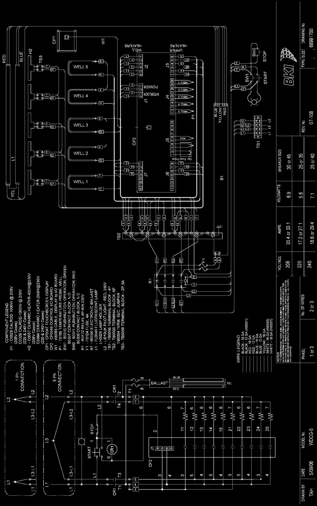
44 Wiring Diagrams Wiring Diagrams 42


45 Wiring Diagrams 43


46 Wiring Diagrams 44


47 Wiring Diagrams 45


48 Wiring Diagrams 46


49 Wiring Diagrams 47


50 Wiring Diagrams 48


51 Wiring Diagrams 49


52 Wiring Diagrams 50


53 Wiring Diagrams 51


54 Wiring Diagrams 52


55 Wiring Diagrams 53


56 Wiring Diagrams 54


57 Wiring Diagrams 55


58 Wiring Diagrams 56
Hot Case Series. SERIES: WDCG Operation Manual
 Hot Case Series SERIES: WDCG Operation Manual 2812 Grandview Drive Simpsonville, SC 29680 USA (864) 963-3471 Toll Free: (800) 927-6887 Fax: (864) 963-5316 WHAT IS COVERED WHO IS COVERED COVERAGE PERIOD
Heated Bakery Merchandiser Series. Series: WBC Operation Manual
 Heated Bakery Merchandiser Series Series: WBC Operation Manual WHAT IS COVERED WHO IS COVERED COVERAGE PERIOD WARRANTY COVERAGE EXCEPTIONS EXCLUSIONS INSTALLATION BKI LIMITED WARRANTY 2812 Grandview Drive
Hot Food Deli Case MODELS WDC, TSW, TCW, SSW, CSW Installation & Operation Manual Serial Numbers and Higher
 MODELS WDC, TSW, TCW, SSW, CSW Installation & Operation Manual Serial Numbers 122556 and Higher BKI LIMITED WARRANTY PO Box 80400 Simpsonville, SC 29680-0400 USA (864) 963-3471 Toll Free: (800) 927-6887
Multi-Shelf Merchandiser Series. SERIES: MDW Operation Manual
 Multi-Shelf Merchandiser Series SERIES: MDW Operation Manual WHAT IS COVERED WHO IS COVERED COVERAGE PERIOD BKI LIMITED WARRANTY 2812 Grandview Dr. Simpsonville, SC 29680 USA (864) 963-3471 Toll Free:
Fry Warmer. MODEL KFW, KFW-21 Service Manual. CS-TM Revised 3/28/13
 MODEL KFW, KFW-21 Service Manual CS-TM-036.01 Revised 3/28/13 BKI LIMITED WARRANTY 2812 Grandview Dr. Simpsonville, SC 29680 USA (864) 963-3471 Toll Free: (800) 927-6887 Fax: (864) 963-5316 WHAT IS COVERED
Fried Food Warmers Series. Series: HFW Operation Manual
 Fried Food Warmers Series Series: HFW Operation Manual BKI LIMITED WARRANTY 2812 Grandview Dr. Simpsonville, SC 29680 USA (864) 963-3471 Toll Free: (800) 927-6887 Fax: (864) 963-5316 WHAT IS COVERED WHO
Easy/Tran TF STANDBY POWER FURNACE SWITCH TOOLS NEEDED FOR INSTALLATION. PARTS LIST for Easy / Tran TF FURNACE TRANSFER SWITCH
 STANDBY POWER FURNACE SWITCH Easy/Tran TF Congratulations on your purchase of the Reliance Controls Easy/Tran TF furnace transfer switch. Reliance has been manufacturing transfer switches and equipment
Installation Instructions PowerBoard Automatic Retracting Running Board
 Installation Instructions PowerBoard Automatic Retracting Running Board Vehicle Application Chevy Silverado/GMC Sierra Extended Cab 2007 and newer (excluding 2011 Diesels) Part Number: 75123-15 Chevy Silverado/GMC
Installation Instructions PowerBoard Automatic Retracting Running Board
 Installation Instructions PowerBoard Automatic Retracting Running Board Vehicle Application Toyota Tundra Double Cab 2007 Current Part Number: 75136-15 Toyota Tundra CrewMax 2007 Current Part Number: 75137-15
Installation Instructions PowerBoard Automatic Retracting Running Board
 Installation Instructions PowerBoard Automatic Retracting Running Board Vehicle Application Chevy Silverado/GMC Sierra Extended Cab 2007 and newer (excluding 2011 Diesels) Part Number: 75123-15 Chevy Silverado/GMC
Installation Instructions PowerBoard Automatic Retracting Running Board
 Installation Instructions PowerBoard Automatic Retracting Running Board Vehicle Application Chevy Silverado/GMC Sierra Extended Cab Diesel 2011 and newer Part Number: 75147-15 Chevy Silverado/GMC Sierra
Instruction Manual. Fudge Puppy Display Case
 Instruction Manual Fudge Puppy Display Case Model No. 5535 10700 Medallion Drive, Cincinnati, Ohio 45241-4807 USA 2014 Gold Medal Products Co. Part No. 89074 SAFETY PRECAUTIONS DANGER Machine must be properly
Installation Instructions PowerBoard Automatic Retracting Running Board
 Installation Instructions PowerBoard Automatic Retracting Running Board Vehicle Application Dodge Ram 1500 Crew Cab 2009 - Current : 75138-15 Dodge Ram 2500/3500 & HD Crew Cab 2010 - Current : 75138-15
INSTALLATION MANUAL ELECTRIC DOUBLE OVEN RANGE
 ENGLISH ESPAÑOL INSTALLATION MANUAL ELECTRIC DOUBLE OVEN RANGE Please read these instructions thoroughly before installing and operating the range. LDE3019ST LDE3017ST LDE3017SB LDE3017SW LDE3015ST LDE3015SB
Installation Instructions PowerBoard Automatic Retracting Running Board
 Installation Instructions PowerBoard Automatic Retracting Running Board Vehicle Application Ford Super Duty F-250/350/450 Crew Cab 2008 and newer Part Number: 75134-15 www.bestop.com - We re here to help!
Installation Instructions
 Installation Instructions www.bestop.com - We re here to help! Visit our web site and click on Ask a Question INSTALLATION TIME SKILL LEVEL Automatic Retracting Running Board Vehicle Application Chevy
Installation Instructions PowerBoard Automatic Retracting Running Board
 Installation Instructions PowerBoard Automatic Retracting Running Board Vehicle Application Ford F150 Super Crew Cab 2009 Current : 75141-15 www.bestop.com - We re here to help! Visit our web site and
Operator's Manual. Storage System. Ultrasound Probe Cabinet. Manufactured by:
 Storage System Ultrasound Probe Cabinet Operator's Manual Manufactured by: CIVCO Medical Solutions 102 First Street South Kalona, IA 52247 USA 319.248.6757 / 800.445.6741 WWW.CIVCO.COM Copyright 2018 All
Source Capture Air Purification System
 Source Capture Air Purification System HA-SCP-G3 Owner s Manual Table of Contents HealthyAir HA-IFM-1111 Filter 1 Important Safety Instructions 2 Technical Specifications 3 Packaging Reference 4 Packing
Solstice Electric Fryers SE Series Service Manual
 Solstice Electric Fryers SE Series Service Manual L22-330 R1 (10/12) Notice In the event of problems or questions about your order, contact the Pitco Frialator factory at (603) 225-6684. In the event of
PHANTOM (PH10 and PH12) COMMERCIAL AND INDUSTRIAL SERIES
 COMMERCIAL AND INDUSTRIAL SERIES") Document No: ICM-IOM Date: 0411 PHANTOM (PH10 and PH12) COMMERCIAL AND INDUSTRIAL SERIES Installation, Operation and Maintenance Manual Please read and save these instructions. Read carefully before attempting
Document No: ICM-IOM Date: 0411 PHANTOM (PH10 and PH12) COMMERCIAL AND INDUSTRIAL SERIES Installation, Operation and Maintenance Manual Please read and save these instructions. Read carefully before attempting
MODEL HD-BTC. Installation, Operation & Repair Parts Information REV041416
 MODEL HD-BTC Installation, Operation & Repair Parts Information REV041416 TABLE OF CONTENTS SAFETY INSTRUCTIONS 1 DEFINITIONS 1 SPECIFICATIONS 2 INSTALLATION INSTRUCTIONS 2 OPERATING INSTRUCTIONS 2 MAINTENANCE
Installation Instructions PowerBoard Automatic Retracting Running Board
 Installation Instructions PowerBoard Automatic Retracting Running Board Vehicle Application Dodge Ram Quad Cab Pickup 2002-2008 Part Number: 75101-15 Dodge Ram Quad Cab Pickup, 2500 / 3500 / HD 2003-2009
Installation Instructions PowerBoard Automatic Retracting Running Board WARNING WARNING WARNING. Support
 Installation Instructions PowerBoard Automatic Retracting Running Board Vehicle Application: Jeep Wrangler 2-Door 2007-2016 Part Number 75651-15 Installation Tips Read and follow, precisely, all installation
Installation Instructions Studio Makeup Station
 Installation Instructions Studio Makeup Station 30" and 36" Models 5-light 30" Studio Makeup Station 8-light 30" Studio Makeup Station 6-light 36" Studio Makeup Station 9-light 36" Studio Makeup Station
Quick Connection Cabinet (QCC)
") Quick Connection Cabinet (QCC) Installation / Operation / Maintenance Manual 400A thru 1200A Ratings, 480Vac Max Quick Connection Cabinet Installation/Operation/Maintenance Manual Page 1 of 6 WARNING!
Quick Connection Cabinet (QCC) Installation / Operation / Maintenance Manual 400A thru 1200A Ratings, 480Vac Max Quick Connection Cabinet Installation/Operation/Maintenance Manual Page 1 of 6 WARNING!
Anthro Mobile Device Charging Carts and Cabinets Owners Manual
 Anthro Mobile Device Charging Carts and Cabinets Owners Manual TECHNOLOGY FURNITURE Hello! Thank you for choosing Anthro. Anthro's Tablet Charging Carts and Cabinets are designed to automatically charge
Installation Instructions PowerBoard Automatic Retracting Running Board
 Installation Instructions PowerBoard Automatic Retracting Running Board Vehicle Application Chevy Silverado/GMC Sierra Crew Cab 1999 2007 (7 ft.) : 75113-15 www.bestop.com - We re here to help! Visit our
Installation Instructions
 Installation Instructions Automatic Retracting Running Board Vehicle Application Ford F150 Supercrew 2001-2003 (2004 Heritage) Part Number: 75111-01 www.bestop.com - We re here to help! Visit our web site
Henny Penny Heated Express Cabinet Model HEC-103 Model HEC-104 Model HEC-123 Model HEC-124
 Henny Penny Heated Express Cabinet Model HEC-103 Model HEC-104 Model HEC-123 Model HEC-124 TECHNICAL MANUAL LIMITED WARRANTY FOR HENNY PENNY EQUIPMENT Subject to the following conditions, Henny Penny
SC Series. Slow Cookers OWNER'S MANUAL
 SC Series Slow Cookers OWNER'S MANUAL Revised: 4 February 2010 SC Series TABLE OF CONTENTS Nu-Vu EQUIPMENT WARRANTY... 3 RECEIPT AND INSTALLATION... 5 INITIAL START-UP... 7 OPERATING INSTRUCTIONS... 9
Henny Penny Rotisserie Display Model SCD-6/8 TECHNICAL MANUAL
 Henny Penny Rotisserie Display Model SCD-6/8 TECHNICAL MANUAL TABLE OF CONTENTS Section Page Section 1. TROUBLESHOOTING... 1-1 1-1. Introduction... 1-1 1-2. Safety... 1-1 1-3. Troubleshooting... 1-1 1-4.
RollSeal 1733 County Road 68 Bremen, Alabama Part No Rev Owner s Manual RS-Divider Curtain
 1. 2. 7 3. 4. RollSeal 1733 County Road 68 Bremen, Alabama 35033 256-287-7000 Part No 4801-5176 Rev 12-11-17 Owner s Manual RS-Divider Curtain Table of Contents 1 Warnings (Avertissements)... 3 2 Limited
Replacement of 600-Ampere Bushing and 200-Ampere Bushing-Well Adapters
 S&C Vista SD Underground Distribution Switchgear Pad-Mounted and Vault-Mounted Style Outdoor Distribution (17.5 kv and 29 kv) With Visi-Gap Load Interrupter Switches and Visi-Gap Fault Inetrrupters Replacement
READ AND SAVE THESE INSTRUCTIONS. ComfortBreeze UV360-1 SYSTEM 24V Ultra-Violet Air Cleaner. Trion
 READ AND SAVE THESE INSTRUCTIONS ComfortBreeze UV360-1 SYSTEM 24V Ultra-Violet Air Cleaner Trion www.trioniaq.com Installation, Operation, & Maintenance Manual 1. Warranty 2. Safety & Warnings ComfortBreeze
Instruction Sheet SRSR SERIES. Rotating Sliding Rail System
 Instruction Sheet SRSR SERIES Rotating Sliding Rail System THANK YOU Thank you for purchasing the SRSR Series Rotating Sliding Rail System. Please read these instructions thoroughly before assembling this
Cincinnati, OH USA
 Astro Pop Warmer Instruction Manual Model #2002 Part No. 61987 Revised July 2000 Cincinnati, OH 45241-4807 USA e-mail: goldme19@eos.net www.gmpopcorn.com SAFETY PRECAUTIONS INTRODUCTION Your new #2002
HARDWARE KIT INSTALLATION GLOVES
 COIL MOUNT STEEL DUCT MOUNT DUCTBOARD MOUNT CLAMP PLATE Z-BRACKET PCO BRACKET SHIELDED LAMP ASSEMBLY ALSO INCLUDED BALLAST TECH MANUAL HARDWARE KIT INSTALLATION GLOVES Rev 1 Issued: 09/03/2014 SERVICE
Installation Instructions
 Installation Instructions AMP RESEARCH Power Step by Bestop Automatic Retracting Running Board Vehicle Application Nissan Titan King Cab 2004 and newer (5 ft.) Part Number: 75106-01 Nissan Titan Crew Cab
Detroit Speed, Inc. Electric Headlight Door Kit Corvette P/N: &
 Detroit Speed, Inc. Electric Headlight Door Kit 1968-82 Corvette P/N: 122006 & 122007 The Detroit Speed Inc. Electric Headlight Door Kit replaces the stock vacuum actuated system on all 1968-82 Corvettes.
model ps600 Address all communications and shipments to: FEDERAL SIGNAL CORPORATION
 MODEL: PS600 HZ: 60 A model ps600 installation and service manual for federal model ps600 FEDERAL SIGNAL CORPORATION POWER SUPPLY VOLTS: SERIES: 120VAC FEDERAL SIGNAL CORPORATION UNIVERSITY PARK, IL. U.S.A.
Installation Instructions PowerBoard Automatic Retracting Running Board
 Installation Instructions PowerBoard Automatic Retracting Running Board Vehicle Application Chevy Silverado/GMC Sierra Extended Cab 2007 Current (excluding 2011 Diesels) Part Number: 75123-15 Chevy Silverado/GMC
EV-2051-M Electric Motor. Operation and Maintenance Manual
 EV-2051-M Electric Motor Operation and Maintenance Manual Table of Contents Safety... 3 General...3 Safety Notices...6 Cautions, Warnings and Dangers...7 Cautions...8 Warnings...11 Dangers...13 Important
FHC-1D user manual. Features
 Phason The Fan and Heater Control (FHC-1D) automatically controls the temperature in a room by adjusting the speed of variable speed fans and controlling a heater interlock. When the temperature is at
The Time Is Right. Installation Instructions. Roast Beef Cooking Controller Upgrade. Model IR081C1H760X & IR081C1H765X
 The Time Is Right 229-51014 Rev. E 1996-2001 Food Automation - Service Techniques, Inc. Installation Instructions Roast Beef Cooking Controller Upgrade Model IR081C1H760X & IR081C1H765X All Products CE
Installation Instructions PowerBoard Automatic Retracting Running Board
 Installation Instructions PowerBoard Automatic Retracting Running Board Vehicle Application Dodge Ram Quad Cab Pickup 2002-2008 : 75101-15 Dodge Ram Quad Cab Pickup, 2500 / 3500 / HD 2003-2009 : 75101-15
WF-5100 Series True Sine Wave Inverters
 Operator s Manual WF-5100 Series True Sine Wave Inverters WF-9900 Series WF-5118 WF-5120 ( The Inverter model number is located on the label on top of the enclosure) Distributed in the U.S.A. and Canada
SUT-250-S (These instructions are used for SUT-250-SCLC also)
") SUT-250-S (These instructions are used for SUT-250-SCLC also) Torque wrench, carpenters square, wire cutters, Phillips screwdriver, 7/16, 9/16, and 3/4 combination wrenches, ratchet, 9/16, 3/4, 13/16,
SUT-250-S (These instructions are used for SUT-250-SCLC also) Torque wrench, carpenters square, wire cutters, Phillips screwdriver, 7/16, 9/16, and 3/4 combination wrenches, ratchet, 9/16, 3/4, 13/16,
1250 LB. CAPACITY MECHANICAL WHEEL DOLLY
 1250 LB. CAPACITY MECHANICAL WHEEL DOLLY 67287 SET-UP AND OPERATING INSTRUCTIONS Visit our website at: http://www.harborfreight.com Read this material before using this product. Failure to do so can result
WARNING: FAILURE TO FOLLOW THESE RULES MAY RESULT IN SERIOUS PERSONAL INJURY CAUTION: INSTALLATION LOCATION:
 2 Please read the safety and installation instructions carefully to help ensure a correct and SAFE installation of your Second Wind Ultraviolet Germicidal Photo-catalytic Air Purifier. WARNING: FAILURE
idrive Power Cord Extender Installation Instructions MODELS: 3960M/3961S (1) 25 POWER CORD DRILL WITH 3/32 DRILL BIT
 25 POWER CORD DRILL WITH 3/32 DRILL BIT") Wayne-Dalton Corp. P.O. Box 67 Mt. Hope, OH 44660 (888) 827-3667 www.wayne-dalton.com idrive Power Cord Extender Installation Instructions MODELS: 3960M/3961S The idrive Power Cord Extender is intended
Wayne-Dalton Corp. P.O. Box 67 Mt. Hope, OH 44660 (888) 827-3667 www.wayne-dalton.com idrive Power Cord Extender Installation Instructions MODELS: 3960M/3961S The idrive Power Cord Extender is intended
Model Numbers SAVI-NOTE75, SAVI-NOTE150
 Installation INSTRUCTIONS & OWNERS Manual SAVI NOTE UNDERWATER LED LIGHT Model Numbers SAVI-NOTE75, SAVI-NOTE150 Safety Precautions...2 SAVI Note Install Instructions...3-4 1 READ AND FOLLOW ALL INSTRUCTIONS
AIM LED LIGHT (ceiling mount)
") AIM LED LIGHT (ceiling mount) Installation Manual AIM LED LIGHT (ceiling mount) INTRODUCTION Lights in the AIM Series are designed to give the professional health care market superior performance, reliability
AIM LED LIGHT (ceiling mount) Installation Manual AIM LED LIGHT (ceiling mount) INTRODUCTION Lights in the AIM Series are designed to give the professional health care market superior performance, reliability
Utility Distribution System
 READ AND SAVE THESE INSTRUCTIONS Utility Distribution System Installation, Operation and Maintenance Manual Warning!! Improper installation, adjustment, alteration, service or maintenance can cause property
Installation Instructions PowerBoard Automatic Retracting Running Board WARNING WARNING WARNING. Skill Level. Installation Time
 Installation Instructions PowerBoard Automatic Retracting Running Board Vehicle Application: Jeep Wrangler Unlimited 2007-2016 Part Number 75652-15 Installation Tips Read and follow, precisely, all installation
Reach ins, Freeezers & Refrigerators Installation & Operation Manual
 Reach ins, Freeezers & Refrigerators Installation & Operation Manual BSR23 BSF23 BSR49 BSF49 BSR72 BSF72 IMPORTANT SAFETY INSTRUCTIONS (SAVE THESE INSTRUCTIONS) Visit us on the web at www.blueairinc.com
Fastback Top Installation Instructions and Owner s Manual
 Fastback Top Installation Instructions and Owner s Manual MODEL: Suzuki Samurai 1985-1989 PART NUMBER Congratulations on your purchasing decision. Bestop designed the Convertible Top to give you years
Henny Penny Hand Breader/Sifter Model HB-11
 Henny Penny Hand Breader/Sifter Model HB-11 TECHNICAL MANUAL TABLE OF CONTENTS Section Page Section 1. MAINTENANCE... 1-1 1-1. Introduction....1-1 1-2. Safety... 1-1 1-3. Replacement of Belt...1-2 1-4.
(Refer to qualified personnel)
") 3875 Cypress Drive Petaluma, CA 94954 800.228.2555 +1.707.773.1100 Fax 707.773.1180 www.gcx.com Installation Guide VHM-P (Non-Locking) and VHM-PL (Locking) Variable Height Arm (Slide-Above-Arm Configuration)
3875 Cypress Drive Petaluma, CA 94954 800.228.2555 +1.707.773.1100 Fax 707.773.1180 www.gcx.com Installation Guide VHM-P (Non-Locking) and VHM-PL (Locking) Variable Height Arm (Slide-Above-Arm Configuration)
E.S.P. Embedded Sensing Probes for Motor Brushes
 E.S.P. Embedded Sensing Probes for Motor Brushes 2/13 Installation & Operating Manual MN609 Any trademarks used in this manual are the property of their respective owners. Important: Be sure to check www.baldor.com
INSTALLATION INSTRUCTIONS SEMI-HIDDEN WINCH MOUNT Part Number:70005 Application: Ford Super Duty
 INSTALLATION INSTRUCTIONS SEMI-HIDDEN WINCH MOUNT Part Number:70005 Application: Ford Super Duty Your safety, and the safety of others, is very important. To help you make informed decisions about safety,
Linear Actuator. Installation Manual. warranty installation parts list. Linear Actuator Installation Manual Page 1
 Linear Actuator Installation Manual warranty installation parts list January 2004 Linear Actuator Installation Manual Page 1 MA1221B12 Warranty Information Chore-Time Equipment ( Chore-Time ) warrants
Florham Park, NJ USA Call (ASCO) for sales or service
 for sales or service") Operator s Manual 4000 Series ATS Automatic Open-Transition Transfer Switches D design 30 230A, J design 260 600A, H-design 800 1200A, G-design 1600 4000A, F-design 4000A DANGER is used in this manual
Operator s Manual 4000 Series ATS Automatic Open-Transition Transfer Switches D design 30 230A, J design 260 600A, H-design 800 1200A, G-design 1600 4000A, F-design 4000A DANGER is used in this manual
Installation Instructions Tigertop
 Installation Instructions Tigertop Vehicle Application Jeep CJ5 1955 1975 Part Number: 51405 Jeep M38, A1 1951 1971 Part Number: 51405 www.bestop.com - We re here to help! Visit our web site and click
OPERATION MANUAL MODELS TWE-250 TWE-321 TWE-375 TRU WELD EQUIPMENT COMPANY 6400 N. HONEYTOWN ROAD SMITHVILLE, OHIO (330)
") OPERATION MANUAL MODELS TWE-250 TWE-321 TWE-375 TRU WELD EQUIPMENT COMPANY 6400 N. HONEYTOWN ROAD SMITHVILLE, OHIO 44677 (330) 669 2773 Version 1.3 Date 10/20/2010 TRU WELD EQUIPMENT LIMITED WARRANTY All
OPERATION MANUAL MODELS TWE-250 TWE-321 TWE-375 TRU WELD EQUIPMENT COMPANY 6400 N. HONEYTOWN ROAD SMITHVILLE, OHIO 44677 (330) 669 2773 Version 1.3 Date 10/20/2010 TRU WELD EQUIPMENT LIMITED WARRANTY All
AS-57FMH Flush Mount Kit AS-57EBDBP
 AS-57FMH Flush Mount Kit AS-57EBDBP Table of Contents GrowerSELECT General Page...3 Safety...4 Warning Labels...4 Installation...5 Operation Safety...5 Maintenance Safety...5 Installation...6 Framing...6
Section 7 - Troubleshooting Guide
 Section 7 - Troubleshooting Guide Section 7 - Troubleshooting Guide IMPORTANT While this troubleshooting guide provides information to aid in troubleshooting problems with the range, it does not contain
Air Curtain. Installation, Operating and Maintenance Instructions
 Installation, Operating and Maintenance Instructions Save this manual for future reference. Air Curtain Model Numbers: ES026, ES036, ES042, ES048, ES060, ES072 READ THIS OWNER S MANUAL CAREFULLY BEFORE
Installation Instructions For Motor Control Center (MCC) Units
 Units") s Page 1 of 8 Installation Instructions December, 2013 Installation Instructions For Motor Control Center (MCC) Units Hazardous voltage. Will cause death or serious injury. Always de-energize and ground
s Page 1 of 8 Installation Instructions December, 2013 Installation Instructions For Motor Control Center (MCC) Units Hazardous voltage. Will cause death or serious injury. Always de-energize and ground
Cutler-Hammer. Instructions for Installation, Operation, and Maintenance of the AMPGARD Reduced Voltage Soft Starter
 Operation, and Maintenance of the Instruction Bulletin Read and understand these instructions before attempting any installation, operation, or maintenance of the. This equipment shall be installed and
Control System. Part B, Section 1. This section covers the following unit configurations. Model Voltage 1, 2 Pump Piston (E, F, or G)
") Part B, Section 1 This section covers the following unit configurations. Model 3100 3400 3500 Voltage 1, 2 Pump Piston (E, F, or G) Manifold 4-Port (A) 6-Port (B or C) Control UniScan (1) B 1-0 B 1-1 Section
Part B, Section 1 This section covers the following unit configurations. Model 3100 3400 3500 Voltage 1, 2 Pump Piston (E, F, or G) Manifold 4-Port (A) 6-Port (B or C) Control UniScan (1) B 1-0 B 1-1 Section
AIM LED LIGHT (wall mount)
") AIM LED LIGHT (wall mount) Installation Manual AIM LED LIGHT (wall mount) INTRODUCTION Lights in the AIM Series are designed to give the professional health care market superior performance, reliability
AIM LED LIGHT (wall mount) Installation Manual AIM LED LIGHT (wall mount) INTRODUCTION Lights in the AIM Series are designed to give the professional health care market superior performance, reliability
Single and Bi-Parting Manual Sliding Doors. Installation. R-PLUS Cold Storage Doors
 Single and Bi-Parting Manual Sliding Doors Installation Door Leaf J-Box Door Heater J-Box Door Header Adjusting Rod Door Hanger Assembly Track Roller Door Track SJO Cable Trailing Edge Door Snubber Neoprene
OPERATING MANUAL AND INSTRUCTIONS
 instruction sheet #361653 RedHots Heat Lamps OPERATING MANUAL AND INSTRUCTIONS CAUTION inspect contents immediately AnD FiLe claim With DeLiVerinG carrier For AnY DAMAGe. SAVE YOUR BOX AND ALL PACKING
Part Number Mini Linear Lift Assembly Installation & Operator s Instruction Manual
 Part Number 39644 Mini Linear Lift Assembly Installation & Operator s Instruction Manual April 1999 MV1505C Chore-Time Warranty Mini Linear Lift Assembly Manual Chore-Time Warranty Chore-Time Equipment
OWNER S MANUAL SELF-PRIMING PORTABLE UTILITY PUMP
 Model 54011-0 OWNER S MANUAL SELF-PRIMING PORTABLE UTILITY PUMP Questions, problems, missing parts? Before returning to the store call AQUAPRO Customer Service 8 a.m. - 5 p.m., EST, Monday-Friday 1-844-242-2475
Installation Instructions
 NOTE: Read the entire instruction manual before starting the installation. This symbol indicates a change since the last issue. SAFETY CONSIDERATIONS Installing and servicing air conditioning equipment
Battery Charger Retrofit Kit Q-DCCHG1 for DC Cabinet Retrofit Manual
 Battery Charger Retrofit Kit Q-DCCHG1 for DC Cabinet Retrofit Manual 25500181 Rev. A0 415 Printed in U.S.A. Copyright 2015 Federal Signal Corporation Limited Warranty The Alerting and Notification Systems
1. Contents 1. CONTENTS INTRODUCTION SAFETY WARNINGS POWER TILT STANDARD OPERATING INSTRUCTIONS... 5.
 1. Contents 1. CONTENTS..... 2. INTRODUCTION..... 3. SAFETY WARNINGS..... 4. POWER TILT STANDARD OPERATING INSTRUCTIONS....... 5. POWER SEAT LIFT STANDARD OPERATING INSTRUCTIONS...... 6. POWER TILT / SEAT
INSTALLATION INSTRUCTIONS TRAILER HITCH MAIN HARNESS KIT
 PART NUMBER: 0000-89-N30 GENUINE ACCESSORIES INSTALLATION INSTRUCTIONS TRAILER HITCH MAIN HARNESS KIT APPLICABLE MODELS: 2016 > CX-9 PACKAGE CONTENTS: INSTALLATION INSTRUCTIONS QTY 1 CABLE TIE MOUNT QTY
Installation Instructions
 Installation Instructions Automatic Retracting Running Board Vehicle Application Dodge Ram Quad Cab Pickup 2002-2005 Part Number: 75101-01 Dodge Ram Mega Cab Pickup 2006 - Current Part Number: 75118-01
HANDY GATE ASSEMBLY, INSTALLATION AND OPERATING INSTRUCTIONS
 ASSEMBLY, INSTALLATION AND OPERATING INSTRUCTIONS BEFORE INSTALLING OR USING THE, REVIEW THE VEHICLE LOADING LIMITATIONS OUTLINED IN THE VEHICLE OWNER S MANUAL AND THE SAFETY COMPLIANCE CERTIFICATION LABEL
Raritan PX. Power Cord Installation Guide. Safety Guidelines. Safety Instructions
 QS Rule Raritan PX Power Cord Installation Guide This installation guide explains how to install power cords on Raritan PX products that do not come with a factory installed power cord. This type of product,
OPERATIONS MAINTENANCE MANUAL
 OPERATIONS MAINTENANCE MANUAL COOK & HOLD OVEN SYSTEMS COMMERCIAL & INSTITUTIONAL SERIES WITTCO MODEL NUMBERS 750-AD-SS 1000-AD-SS 1200-AD-SS 1400-AD-SS 750-AD-SS-IS 1000-AD-SS-IS 1200-AD-SS-IS 1400-AD-SS-IS
Automated I.V. Stand Cat. No OPERATOR S MANUAL. Operation& Maintenance Instructions. Raising the Standard of Care!
 Automated I.V. Stand Cat. No. 741314 OPERATOR S MANUAL Operation& Maintenance Instructions Raising the Standard of Care! Table of Contents Warranty....................... 2 Hardware.......................
FD Conveyor for FD 260 Tabber
 FD 260-20 Conveyor for FD 260 Tabber Operator Manual 1/2011 First Edition TABLE OF CONTENTS 1. INTRODUCTION... 1 1.1 FD 260-20 DESCRIPTION... 1 1.2 ITEMS INCLUDED... 1 1.3 OPERATING MANUAL SAFETY TERMS...
U00X ULTRASONIC LEVEL SWITCH. Ultrasonic Liquid Level Switches INSTALLATION AND OPERATIONS MANUAL. For Models: U002, U003 & U004
 U00X ULTRASONIC LEVEL SWITCH INSTALLATION AND OPERATIONS MANUAL Ultrasonic Liquid Level Switches For Non-Hazardous Locations For Models: U002, U003 & U004 READ THIS MANUAL PRIOR TO INSTALLATION This manual
TOYOTA COROLLA ILLUMINATED DOOR SILLS Preparation
 Preparation Part Number: PT942-02140 Kit Contents Item # Quantity Reqd. Description 1 1 Illuminated Scuff plate, Front Right Hand 2 1 Illuminated Scuff plate, Front Left Hand 3 1 Door Scuff plate, Rear
Dispenser & Warmer RIC-1909 RIC-1909EXP
 Dispenser & Warmer RIC-1909 RIC-1909EXP Safety Precautions CAUTION This equipment is designed and sold for commercial use only. This equipment is not to be used by the consumer in home use. Do not allow
TOYOTA FJ CRUISER AIR DAM/LIGHT BAR Preparation
 Preparation Part Number: PT278-35071 Kit Contents Item # Quantity Reqd. Description 1 1 Air Dam / Light Bar Hardware Bag 1 Contents Item # Quantity Reqd. Description 1 2 Screw, M6x33mm, Wafer Head 2 2
SPC-PANEL Simplex, Single Phase Pump Control Panel
 Pump Installation and Service Manual SPC-PANEL Simplex, Single Phase Pump Control Panel Pump Controls for 2 HP Grinder Pumps NOTE! To the installer: Please make sure you provide this manual to the owner
Detroit Speed, Inc. Electric Headlight Door Kit Corvette P/N: &
 Detroit Speed, Inc. Electric Headlight Door Kit 1968-82 Corvette P/N: 122006 & 122007 The Detroit Speed Inc. Electric Headlight Door Kit replaces the stock vacuum actuated system on all 1968-82 Corvettes.
Electric Range installation manual
 Electric Range installation manual This manual is made with 100% recycled paper. imagine the possibilities ENGLISH Thank you for purchasing this Samsung product. To receive more complete service, please
Junior Sandblaster. Model #51 WARNING! FOR YOUR SAFETY PLEASE READ INSTRUCTIONS BEFORE OPERATING TOOL & WEAR EYE PROTECTION
 Junior Sandblaster Model #51 WARNING! FOR YOUR SAFETY PLEASE READ INSTRUCTIONS BEFORE OPERATING TOOL & WEAR EYE PROTECTION PARTS LIST AND PART NUMBERS 01.Red Rubber Air Hose (5Ft) P51-01 02. Male Insert
UV DISINFECTION UNIT MODEL 3G
 SALCOR INC. P. O. Box 1090 Fallbrook, CA 92088-1090 Telephone: (760) 731-0745 Fax: (760) 731-2405 INSTALLATION MANUAL UV DISINFECTION UNIT MODEL 3G February, 2011 I. INSTALLATION INSTRUCTIONS WARNING!
Installation Instructions Electric Heaters 5 20 kw
 Small Packaged Products 2 to 5 Tons Accessory Electric Heaters Cancels: IIK 564A-24-2 IIK 564A-24- -02 Installation Instructions Electric Heaters 5 20 kw NOTE: Read the entire instruction manual before
E E VDC COOLEDGE TILE INTERIOR INSTALLATION INSTRUCTIONS. Caution: Observe precautions for handling electrostatic sensitive devices.
 5 YEAR WARRANTY 5 YEAR WARRANTY COOLEDGE TILE INTERIOR INSTALLATION INSTRUCTIONS E354088 LISTED AC E354088 58VDC E354088 E354088 5 5 YEAR WARRANTY 5 YEAR WARRANTY E354088 Caution: Observe precautions for
14", 18" & 24" Fiberglass Turbo Fans Installation & Operator s Instruction Manual
 14", 18" & 24" Fiberglass Turbo Fans Installation & Operator s Instruction Manual 09484:09#52
2 Piece Soft Door Installation Instructions
 2 Piece Soft Door Installation Instructions For: Wrangler/TJ (1997-on) Part Number: 51789 Note: Use of this product will eliminate the factory side mirrors and requires the removal of the entry light bulbs.
Installation Instructions Supertop NX Twill
 Installation Instructions Supertop NX Twill Vehicle Application: Jeep Wrangler Unlimited 2007 Current Part Number: 54823 www.bestop.com - We re here to help! Visit our web site and click on Ask a Question.