INSTRUCTION BOOK Type 50-DH-250 and 75-DH and 2000 Ampere "De-Ion" Power Air Circuit Breakers 5000 Volts and 7500 Volts Built Since 1945
|
|
|
- Albert Jones
- 6 years ago
- Views:
Transcription
1 INSTRUCTION BOOK Type 50-DH-250 and 75-DH and 2000 Ampere "De-Ion" Power Air Circuit Breakers 5000 Volts and 7500 Volts Built Since 1945 (formerly Westinghouse Electric Corporation) 820 Washington Boulevard Pittsburgh, PA (USA) Phone: or Fax: Permission to use, copy and distribute the documentation published by Homewood Products Corporation on this World Wide Web server is hereby granted on the condition that each copy contains this copyright notice in its entirety and that no part of the documentation is used for commercial purposes but restricted to use for information purposes within an organization. All information published on this world wide web server is provided as is without any representation or warranty of any kind either express or implied including but not limited to implied warranties for merchantability, fitness for a particular purpose or non-infringement. Any Homewood Products Corporation documentation may include technical inaccuracies or typographical errors. Changes and additions may be made by Homewood Products Corporation from time to time to any information contained herein. Copyright 2001 Homewood Products Corporation. All rights reserved. Publication I.B C293 (MH-663-A Publication Date Unknown
2 Index Inquiry Data... ii Preface... iii Description... 1 General... 1 Solenoid Mechanism... 1 Contact Assembly... 1 Arc Chutes & Magnetic Circuit... 1 Interphase Barriers... 2 Receiving, Handling & Storage... 2 Inspection & Handling... 2 Storage... 2 Installation... 3 Installing the Equipment... 3 Caution... 4 Operation... 4 Principles of Operations... 4 Operating Instructions... 4 Caution... 4 Service Inspection... 4 Recommendations for Inspection Schedule... 4 Lubrication... 6 Maintenance, Overhaul and Repair... 6 Safety for Personnel... 6 General Discussion...? Magnetic Circuit... 7 Arc Chutes... 7 Contacts... 7 Adjustment of Moving Contact Arms... 8 Solenoid Mechanism... 8 Puffer Assembly... 9 Dismounting Instructions & Inspection Check List... 9 Tripping Attachments... 9 Shunt Trip... 9 Capacitor Shunt Trip Page Renewal Parts i
3 INQUIRY DATA When communicating regarding a Product covered by this Instruction Book, replies will be greatly facilitated by citing Complete Name Plate Readings of the involved Products. Also, should particular information be desired, please be very careful to clearly and fully state the Problems and Attendant Conditions. ii
4 PREFACE The purpose of this instruction book is to acquaint the recipient with the characteristics of the Type 50-DH-250 and 75-DH-250, Air Circuit Breakers. Instructions necessary for installation, operation and maintenance will be found in this book. The Type DH Air Circuit Breaker has proven very satisfactory in service since it was first marketed in 1939 and all the accumulated experience of many years in power air circuit breaker work has been applied to this line of breakers. Fundamentally a circuit breaker is a device for interrupting a circuit between separable contacts under normal load or short circuit conditions. The Type DH "De-ion" Air Circuit Breaker is designed to operate in an ordinary air atmosphere and is not dependent on the maintenance of any stored medium, such as compressed air or liquid dielectric. Its performance is dependable, clean-cut and free from uncertainty. iii
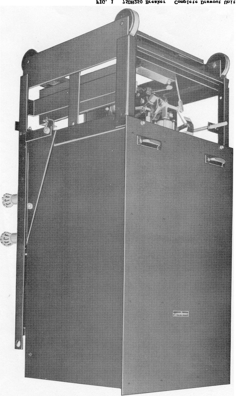
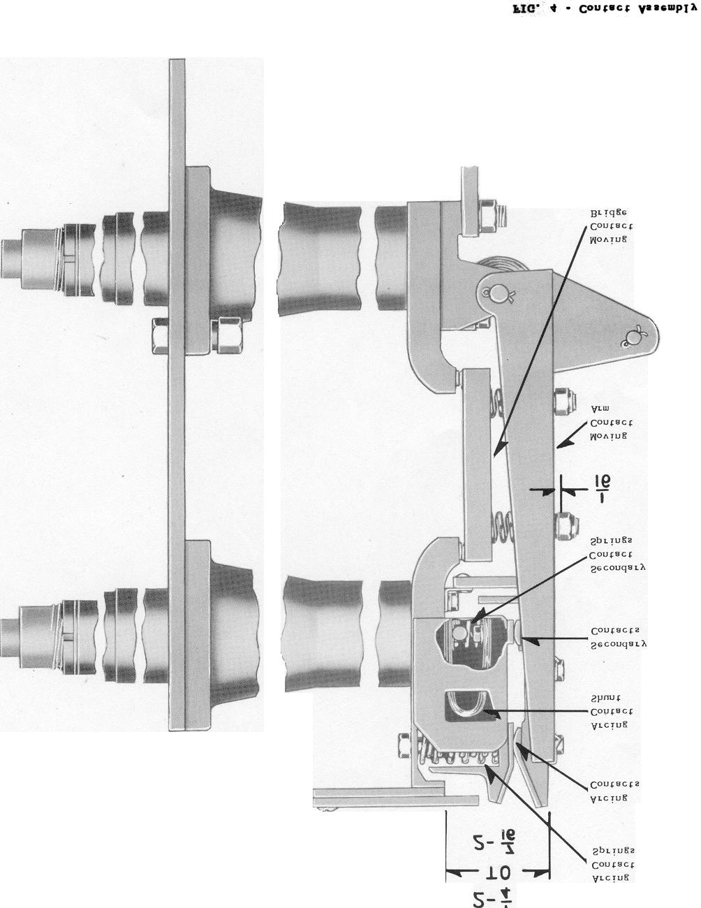
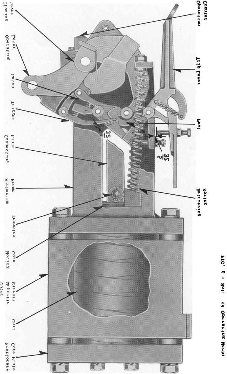
5 DESCRIPTION General Figures 1 & 2 show a 1200 ampere, 7500 volt, Type 75-DH-250, 3 pole air circuit breaker mounted as a removable unit for Metal Clad Switchgear use. This breaker was designed for indoor service at alternating current voltage of from 4000 to 7500 volts, for normal current loads up to 1200 or up to 2000 amperes and for an interrupting duty of 250 thousand KVA at 25 and 80 cycle frequency. The Type 50-DH-250, 3 pole air circuit breaker is similar to the Type 75--DH-250 except that it was designed for a range of alternating current voltages of from 4000 to 5000 volts. The figure preceding the letters DH in the type number of the breaker designates the voltage rating in hundreds of volts while the number following the letters DH indicates the interrupting rating in thousands of kilovolt amperes (kva). Example: Type 75-DH-250 signifies a 7500 volt breaker with an interrupting rating of 250,000 kva. These breakers are characterized by long life and moderate maintenance requirements when operated under severe duty. The breaker parts are mounted on a chair-shaped framework, the back of which is used to support the individual pole units, each with its own contacts, arc chute and magnetic circuit. The three moving contact arms are operated through a crossbar and operating rods by a single solenoid mechanism. The solenoid mechanism occupies the lower part of the breaker frame while the moving contact arms, bushings, and arc chutes occupy the upper part. Primary or main current connections are made at the rear of the breaker to the bushings. The breaker weighs approximately 1700 lbs. Breaker dimensions are shown in Figure 3, Page 12. Figure 3, page 12 shows a diagram of the breaker in which the various parts are indicated by means of arrows. The primary disconnecting contacts have 9 and 15 segments in each cluster for the 1200 and 2000 ampere ratings respectively. The solenoid mechanism, with auxiliary switches, secondary contacts, tripping accessories and all low voltage wiring is located below the high voltage parts and isolated from them by a horizontal steel barrier. A vertical framework rising upward from the horizontal steel barrier, supports the bushings, contacts, magnetic circuits and arc chutes, all these parts being at high potential. A metallic plate fastened across the front of the interphase barriers confines the high potential zone to the space behind the vertical metallic barrier. Solenoid Mechanism The operating mechanism Fig. 6, page 15, supplied with Type DH breakers is of the direct-current solenoid type. It is mounted so that the moving core, operating in a horizontal plane, acts through a toggle linkage to open and close the breaker contacts. The necessary tripping devices form a part of the mechanism. Auxiliary switches with ten contacts are supported from the removable unit framework and mechanically connected to the linkage which operates with the breaker contacts. A cut-off switch, operated by the moving core is supplied to close or open a control circuit for interruption of the closing coil current. Contact Assembly The breaker contact structure must be capable of carrying normal load currents and of drawing the arc during the interrupting periods in a manner so that after the interruptions, the contacts will be in such condition that the load currents can be carried without undue temperature rise. The stationary main contacts consist of silver-nickel inserts which are brazed to the bushing studs. The moving main contacts are of the same material and are brazed to self-aligning bridge members. In the closed position the silver bars engage to complete the main current path through the breaker. Contact pressure is maintained by compression springs placed between the bridging members and the moving arms which carry the bridging members. See Fig. 4, contact assembly. Arc Chutes and Magnetic Circuit The arc chutes are located immediately above the arcing contacts of each pole unit. The 1
6 insulating sides of the arc chutes extend downward past the upper contact members to insure a positive transfer of the arcs into the chutes. Each chute consists of laterally spaced ceramic plates having V-shaped slots and held together with a moisture and heat resisting cement. An arcing horn is provided at each end of each chute. The series of V-shaped slots in the plates form a vented groove or slot extending the length of the arc chute into which the arc is drawn and extinguished. As shown in Fig. 5, page 14, a multi-turn coil, located immediately behind the arc chute and above the stationary contact, is inserted into the electrical circuit by the transference of the arc terminal from the stationary arcing contact to the arcing horn which is immediately above it. This coil then generates a magnetic flux which is directed across the arc path by the laminated pole faces along the sides of the arc chute. The flux across the gap between the pole faces and through the arc chute forces the arc upward into the interrupting slot. Interphase Barriers The interphase and front barriers are built into a single assembly which slides in place and is held in position by two bolts which attach the lower end of the front barrier to the unit frame. RECEIVING, HANDLING, AND STORING Inspection and Handling As with many types of electrical equipment, the "DH" Air Circuit Breaker requires ample packing and careful handling to avoid damage in transit. The breakers are completely assembled and tested at the factory. The arc chutes are then removed and shipped separately in a wooden box with many sheets of corrogated paper used to cushion the chutes. The barrier assembly is also boxed separately from the breaker. The main breaker is crated and supported in such a manner that it cannot roll in the crate. Immediately upon receipt of a circuit breaker an examination should be made for any damage sustained while enroute. If injury is evident or indication of rough handling is visible, a claim should be filed at once with the Transportation Company and the nearest Westinghouse Sales Office notified promptly. Unloading and uncrating the breaker requires very careful work. The base of the crate to which the breaker is fastened may be used as a skid in moving the breaker around. DO NOT USE LONG BARS to uncrate the breaker as they may slip through the crating and damage the equipment; a NAIL PULLER is recommended for that particular purpose. If a crane is available for removing the breakers from the crates considerable time can be saved in unpacking. The lift should be made by using the holes provided in the upper part of the frame. The approximate net weights are as 1200 Amp. 3-pole brkr. without Arc Chamber and Barrier, 1400 lb Amp. 3-pole brkr. without Arc Chamber and Barrier, 1500 lb Amp. 3-pole brkr. Main Barrier, 90 lb. each. Storage Three Arc Chamber, 60 lb. each. The arcing chambers and barriers are shipped in containers separate from the breakers to guard against rough handling and for more secure protection against dust and moisture. These breakers should be put in a clean dry place immediately upon arrival. During this storage period they should be kept sufficiently warm to prevent moisture condensation until placed in service. 2
7 INSTALLATION Installing the Equipment With the exception of the arcing chambers and barriers, the breakers are shipped completely assembled and adjusted. No change in adjustments should be required and none should be made unless it is obvious that they have been disturbed. The following sequence of operations should be followed in preparing the breaker for use. 1. Caution: Severe injury may be suffered if any part of the body is struck by the contact arms since they move very rapidly on the opening stroke. Therefore personnel working about the breaker should stay clear of the space in which the contact arms move while breaker is closed or is being closed, because the breaker may be accidentally tripped. 2. Breakers are usually shipped with the contacts closed and with a tie on the trip lever to prevent the breaker being tripped. After unpacking the breaker and removing all other shipping braces and ties, remove the tie on the trip lever and trip the breaker. Then close the breaker carefully by hand using the emergency hand close lever to make certain that all parts are functioning properly and that there is no binding or excessive friction. As the contacts touch near the end of the closing stroke, the force necessary to close the breaker increases rapidly. 3. Check contacts to make certain that adjustments have not been distributed. Refer to Fig. 4, Contact Assembly, for contact settings. The two required settings can be easily made as follows: a. 1/16 in. adjustment can be made with a thin wrench. All four nuts on each pole unit should be adjusted to this dimension. b. 2-1 /4 to 2-7/16 in. adjustment can be made by changing the length of the operating rods at the lower end of the rods. See Fig. 3 for location of operating rods. A light film of grease is applied to both the arcing and main contacts before the breaker is operated on the test floor. This film normally is removed before shipment. Before the breaker is placed in service, the arcing contacts should be inspected to see that they are free of oil or grease. The breaker is more easily handled with the arc chambers and barriers removed. Hence it is advisable to mount these parts after the breaker has been moved near the metal clad cell structure. 4. Inspect arc chutes to make certain that the vents and slots are open and free from foreign material. If possible, a stream of dry compressed air should be played through them from top to bottom and vice versa. The arc chutes may then be assembled on the breaker by resting their supporting surfaces on the pole faces of the magnetic circuit and sliding them into position using the pole faces as a guide. See Fig. 3 for location of pole faces and arc chute supporting surfaces. After the arcing chute has been placed in position check to see that, (1) the contact blade of the rear arcing horn has engaged the lead to the multi-turn coil, (2) that the arc chutes are centrally located so there is no interference with the travel of the moving contacts, and (3) that the chutes are securely held in such a position by the retaining straps at the front of the arc chutes so that the top of the chutes are parallel to the tops of the laminated pole faces. Connect the shunt strap to the front arcing horn in the arc chute. Check the tightness of the lower connection of the shunt straps as they may have loosened during transit. The breaker should then be operated slowly by hand to observe that there is no interference in the movement of the moving contact. 5. The interphase barrier may then be bolted into position. 6. The control wiring should be thoroughly tested for possible grounds and short 3
8 circuits that might have developed during the installation period. The breaker is now ready to be placed in the metal clad cell and operated electrically. Caution When this drawout equipment is put into the cell and moved in beyond the test position, the high voltage parts of the breaker will be energized. If the barrier is completely assembled onto the breaker, personnel will be protected from contact with live parts. If however the barrier assembly were left off, and the breaker rolled into the cell, live parts would be exposed. Therefore the breaker should never be rolled into an energized cell structure without having the complete barrier assembly in place. OPERATION Principles of Operation Figure 5 shows a typical arrangement of the fundamental part of the Type "DH De-ion" Air Circuit Breaker. The operation of the circuit breaker will be more clearly understood by referring to that figure while reading the remainder of this paragraph. The arcing contacts are so arranged that they form a loop in the current path through the breaker, (1). The magnetic effect of this loop extends the arc rapidly upward as the contacts open, (2). Due to this looping effect, the arc almost instantly impinges against the fixed horn in the arcing chamber immediately above the stationary contact so that one arc terminal transfers to this horn, the other arc terminal remaining on. the moving arcing contact momentarily, (3). The transfer of the arc to the arc horn alters the current path through the breaker to include the multi-turn coil as that coil is not carrying current when the breaker is in the closed position. Current flowing through that coil produces a magnetic flux which moves the arc upward into the arcing chamber and the second arc terminal from the moving arcing contact to the arcing horn at the front end of the chute, (4). A shunt strap connects this front horn to the lower breaker terminal, thus relieving the contacts of current carrying duty, until the arc is extinguished in the slot of the arc chamber, (5). Operating Instructions The breaker should be prepared for use as previously described under the heading, "Installation", on page 2. The breaker may then be placed in the metal clad cell in the "Test" position. In this position, the main breaker connections are still not touching and the breaker is still 12-1/2 inches from the end of its normal horizontal movement. In the test position, the secondary contacts, located near the bottom of the breaker, may be pushed into position and the breaker may be operated electrically. After successful electrical operation, the breaker is ready to be cranked into its final position in the cell. Caution The use of the closing lever to close the breaker when the breaker is completely in the cell (after having been cranked into final operation position) should not be practiced. Manual operation of a power air circuit breaker on an energized circuit is not recommended. SERVICE INSPECTION Recommendations for Inspection Schedule The frequency of inspection, cleaning, etc., will depend upon the activity and duty to which the breaker is subject and upon the cleanliness of the atmosphere. For normal applications of the breakers described herein it is recommended that a preliminary or visual inspection be made every three months. A complete inspection, including removal of the stacks for cleaning, should be made every twelve months. Westinghouse power air breakers are constructed of the best materials for the purpose, based on many years of experience in building and applying such breakers. They are therefore durable pieces of equipment and have a long life 4
9 under normal conditions of operation. However, it is to be recognized that conditions will vary widely and deterioration may appear more rapidly in some cases than others. The working parts of any mechanical apparatus will wear enough to require replacement eventually if subject to sufficient duty. Contacts and arc chutes also will eventually require replacement. It is manifestly impossible to make life predictions for all varieties of applications but in normal central station applications, and barring abnormal conditions, years of service may be expected before extensive parts replacement is required. In highly repetitive service such as motor starting, arc furnace and other industrial applications, maintenance will be determined by the number of operations, dirt, grit or other harmful substances which settle on the breaker parts and the care with which the breaker is kept clean and in proper adjustment. Experience on a given application will prove to be the best guide for maintenance and parts replacement but the following table will serve as a rough guide for those who have no previous experience with Westinghouse power air circuit breakers. For more detailed information regarding the application of Power Air Circuit Breakers, refer to Westinghouse Application Data , and N. E. M. A. Rule SG
10 Inspection Detail Frequency of Operating Duty Mod- Repe- Up to 5 Oper. erate 15 Oper. titive 30 Oper. Highly Repetitive 60 per dy. Per dy. Per dy. Oper. Upward per dy. Clean External Surfaces 3 Mos. 3 Mos. 2 Mos. Every 2500 or 5000 Operations Blow Out Arc Chute 6 Mos. 3 Mos. 2 Mos. Every 2500 or 5000 Operations Remove and Clean Arc Chute 12 Mos. 6 Mos. 4 Mos. Every 2500 or 5000 Operations Inspect Contacts 6 Mos. 6 Mos. 4 Mos. Every 2500 or 5000 Operations Inspect Mechanical Parts 12 Mos. 6 Mos. 4 Mos. Every 2500 or 5000 Operations Lubrication It is desirable to apply a light lubricating oil to the various pin joints throughout the breaker with the following exceptions. The exceptions listed below should not be oiled but should be kept clean and free from dirt and grit (a) All electrical contact surfaces including main bridges; arcing contacts, contact blade of rear arc horn and auxiliary switch contacts. (b) Trigger surfaces on electrical mechanism. Care should be taken that excess oil is wiped off the operating rods, main bushings and other insulating surfaces MAINTENANCE, OVERHAUL AND REPAIR Safety for Personnel The maintenance, overhaul and repair of circuit breaker equipment requires that certain precautionary measures be taken to prevent accidents. The following list presents a few suggestions of that nature. (1) Do not touch a Live Breaker. Parts of the circuit breaker above the horizontal steel barrier are at line potential of the circuit to which the circuit breaker is connected. The circuit breaker should be isolated from the circuit by withdrawal from the cell in the case of metal clad equipment or by disconnecting switches. (2) Whenever possible the breaker contacts should be in the open position when any work is being done. If that is impossible it is desirable to secure a loop over several moving contact arms and around the upper part of the stationary contacts so that the contacts will not accelerate out to the full-open position should the breaker be accidentally tripped. (3) Never lay tools, such as wrenches and screw drivers, etc., on any portion of the circuit breaker as they maybe forgotten and cause trouble. (4) When assembling the arc chutes onto the breaker, check to see that, (a) the contact blade on the stack has engaged the connection to the multi-turn coil, (b) that the arc chutes are centrally located so there is no interference with the travel of the moving contacts; (c) and that the chutes are securely held in a position by the retaining straps at the front of the arc chute so that the top of the chute is parallel to the upper surfaces of the magnetic pole faces; (d) that the shunt strap connecting the front arc horn to the lower bushing is tightly bolted in place, and (e) that arc chute and breaker ratings, as shown by markings and nameplate, agree (5) When lifting the breakers; remove the arc chutes and main barrier. (6) Replace any arc chute after the ends of the slots have become 3/16 inch wide through erosion. (See "Arc Chutes" under Maintenance, Overhaul and Repair on next page.) 6
11 Magnetic Circuit The magnetic circuit assemblies consist of the multi-turn coils, the magnetic pole faces and yokes. Each assembly is attached to and insulated from the upper rear part of the frame by micarta supports. Arc Chutes It should be borne in mind that the insulating parts of the arc chute remain in position across the contacts at all times. During the time that the contacts are in the open position these insulating parts are subjected to the full potential across the breaker. Ability to withstand this potential will depend upon the care given the insulation the arc chute. On general inspections the arc chute should be blown out with dry compressed air by directing the air stream upward from the contact area and out through the stack. Direct the dry air stream thoroughly over the arc box shields (boxlike compartment in which the arc is drawn) and through each space between adjoining plates in the stack. The arc chute should be removed periodically for a thorough inspection. The ceramic material in the arc chutes may have a dirty appearance from repeated arc interruption and still have high dielectric strength. If in doubt apply an alternating current voltage test of 25 KV for not more than one minute to breakers to which this book applies. Too frequent testing in this manner is to be avoided as that in itself may cause deterioration. Any unwanted residue of dirt or arc products should be removed by a vigorous brushing or sanding. A wire brush should not be used for this purpose due to the possibility of embedding metallic particles in the ceramic material. Inspect the stack of plates for metallic deposits, breakage or evidence of undue deterioration. The arcs chutes derive considerable of their interrupting ability from the narrow upper end of the V-slots. That portion of the slot is nominally 1/16 inch wide. When the interrupting duty on highly repetitive service has caused the upper extremity of the slots to increase in width to 3/16 inch, the arc chutes should be replaced or returned to the factory for overhaul. After the arc chute has been replaced and is in position, inspect to make certain that the contact of the rear arc horn in the chute has engaged the connection to the multi-turn coil; that the upper edge of the arc chute is parallel to the magnetic pole faces and that the front arcing horn is securely connected to the lower bushing by means of the shunt straps. Also check by operating the moving contacts to make sure there is no interference with the arc chute sides. Contacts The contacts should be inspected periodically for wear and for evidence of undue burning. Under normal conditions the contacts should be useable for a large number of operations within the rated, interrupting capacity of the breaker. A moderate amount of pitting on the main contact surfaces will not impair their current carrying ability because of the liberal surfaces and high contact pressure used. Any excessive roughness as indicated by loss of contact area on the main contact surfaces may be removed with a fine file or sandpaper. Emery cloth is not recommended for this purpose. Avoid removing excessive amounts of contact material as it may cause misalignment or abnormally short life. The breaker should be opened slowly by hand to determine whether the several contact surfaces part in proper sequence: The sequence on opening should be as follows; (1) main contacts part; (2) secondary contacts part; (3) arcing contacts part. When the contacts become worn to the point of changing this sequence of parting they should be replaced. This condition should not appear until the breaker has had a large number of operations. The breaker should be operated slowly by hand to make sure that there is no excessive friction or binding and that the moving contact arm passes to the full-open position. These breakers are fully adjusted and tested at the factory and no readjustment should be necessary unless it is evident that something has been changed. If it becomes necessary to 7
12 remove the contacts or if for some reason, the breaker has been disassembled, refer to Fig. 4, page 13 and proceed with the contact adjustment as follows. Adjustment of Moving Contact Arms The linkage between the moving contact arms of a multi-pole breaker and the closing mechanism consists of the insulating operating rods and the cross-bar. The cross-bar is omitted in a single pole breaker. The length of this linkage is adjusted to satisfy each pole unit requirement by turning the rod in or out of the threaded hole in the crossbar then locking in place with the lock-nut at that point. This linkage should be so adjusted that when the mechanism is in the latched-closed position the distance between the upper forward surface of the top upper stud block and the inner surface of moving contact arm is from 2-1/4 to 2-7/16 inches. See Fig. 4. It is not necessary to adjust the moving contact arms and operating rods to make the arcing contacts on the several poles strike exactly simultaneously on closing. This adjustment is checked by closing the breaker slowly by hand and is sufficiently close if when the first arcing contacts touch, the greater distance between arcing contacts on the other two poles is not more than 3/16 inch. The main contact bridging members are held in position on the moving contact arm by studs which pass through the main contact springs. Adjustment of the main contacts is made, when the breaker is in the latched position, by setting the stop nuts on these studs so that there will be approximately 1/16 inch clearance between the face of the nut and the back of the moving contact arm. If this 1/16 clearance appears to have been lost due to wear or burning of the main contact surfaces, it may be regained by readjustment once of the stop nuts. The next time clearance on the stop nuts is lost, readjustment should be made on the operating rods as described above. The main bridging members should be replaced before the silver wears completely thru to copper. The arcing and secondary contacts, both moving and stationary, are faced with an arc resisting silver-tungsten material. This material is hard and resists wear well. Moderate burning and pitting are to be expected. Normally, many operations may be obtained before replacements of the arcing contacts are required. However, presence of the tungsten material on the arcing contacts is essential to proper operation of the interrupter. Therefore arcing contacts should be replaced before the contact material is worn completely thru to the cast base material. If new contacts are being installed or if the contacts have just been smoothed it is well to operate the breaker electrically several times so that the surfaces are "worked together" before making this adjustment. See Fig. 4, Contact Assembly. On the opening stroke, the stationary arc horn of the arcing contact should follow the moving arcing contact approximately one inch before parting. Solenoid Mechanism The mechanism Fig. 6 should be inspected at regular intervals, making a number of operations both electrically and by hand to assure that it is functioning properly. It is desirable to apply a light lubricating oil to the various pin joints but not to the extent of causing them to become gummed or sticky. Moving parts, particularly the trigger and switches, should be kept free from dirt and foreign matter. The solenoid mechanism consists essentially of the mechanism frame, outer magnetic circuit, stationary core and plate, coil, coil tube, roving core, retrieving springs, moving core, trunnion, closing lever, connecting links, operating lever, trigger, pawl and trip lever. The brass coil tube is spun onto the stationary core and the end projected through the hole in the mechanism frame casting so as to be visible, its end extending along the side of the moving core. The closing coil can be removed by unscrewing the four bolts, which support the stationary core plate. This plate, stationary core, 8
13 and closing coil can then be removed. In replacing the coil make certain that the moving core travels freely in the brass coil guide tube and that the coil is held firmly in position with wooden wedges to avoid damaging the insulation during electrical operations. Thus no adjustment of the breaker need be disturbed in replacing a closing coil. When shipped from the factory the mechanism has been adjusted and tested and no changes should be necessary. If for any reason reassembly in service becomes necessary, certain relations should be obtained. In the factory the mechanism is bench assembled and during that operation the stops on the closing lever and the mechanism frame are fitted to secure proper clearance when the parts are in the latched closed position and the moving core retrieving springs are pushing the closing lever against the pawl. The shims between the moving core and the trunnion are selected to secure proper clearance between the stops when the mechanism is held closed with the hand closing lever. The tripping lever position is controlled by two bolts. The lever normally rests on a screw which is so set as to obtain a clearance of approximately 1/32 inch between the trip lever and the trigger. The travel of the tripping lever into the tripping position is limited by setting the screw which extends upwards through the trip lever to secure a 5/32 inch clearance between that screw and the mechanism frame when the trip lever is in the normal position. CAUTION: A breaker should never be tripped when the air dash pot (bumper) is disconnected from the operating mechanism. Puffer Assembly The puffer assembly (See Figure 3) is supplied only on the Type 75-DH-250 and is not ordinarily on the Type 50-DH 250 breaker. This assembly supplies a puff of air which is effective in speeding the extinguishing of low currents. Dismounting Instructions & Inspection Check List After the breaker has been removed from the metal clad cell, the following steps should be followed: (1) Remove large barrier covering the upper half of breaker (interphase barrier) inspect for smoked spots and wipe clean. (2) Remove arc chutes - Inspect for breakage of plates, metallic deposits and dirt in chute slots. Blow out chute with compressed air and clean any remaining residue by vigorous brushing. A wire brush is not recommended. Chutes with broken plates should not be used again but should be replaced with new chutes. ( 3) Check contacts by operating breaker with hand closing lever - Inspect for excessive roughness on bridges and proper adjustments. See Figure 4 for proper adjustments - Any roughness on main or bridge contacts may be removed with a fine file or sandpaper. Too much filing may shorten life. Top or arcing contacts may be left slightly rough. Readjust contacts to obtain proper clearance as per Figure 4. (4) Check solenoid mechanism by operating with close lever - inspect for loose bolts or excessive friction of moving parts. Tighten loose bolts and oil all pins with light lubricating oil. Trigger and switches should be clean and free from oil. (5) Check rest of breaker for loose bolts or excessive wear. Wipe off all parts and tighten loose bolts. Replace any parts excessively worn that might affect mechanical operation of the breaker. (6) Check wiring -- Inspect for shorts and grounds - Any defective wiring should be replaced. Tripping Attachments SHUNT TRIP The tripping unit Figure 7, is mounted on the left hand side of the mechanism. Upon energizing a trip coil a magnetic flux is 9
14 generated which causes the moving core to operate, through a rod or bolt, upon a trip lever to trip the breaker. The total travel of the moving core is approximately one inch and the mechanism is so adjusted that the core can move approximately 1/4 inch before engaging the trip lever. When moving the core slowly upward by hand there should be at least 1/16 inch permissible travel of the core when the circuit breaker trips Shunt trip coils are designed for momentary current carrying service and for that reason the shunt trip circuit should be interrupted by auxiliary contacts immediately after breaker is tripped. It is Westinghouse Practice to use for this purpose the first and third contact segments of the ten pole auxiliary switch as counted from the auxiliary switch operating arm end. LOW ENERGY OR CAPACITOR SHUNT TRIP The capacitor shunt trip as applied to these Type DH breakers is a low energy tripping device as shown on Figure 8, Page 17. In it the actual power for tripping is secured by an actuating spring which is latched in the extended position while the breaker is in the open position - the actuating spring having been extended by the action of the resetting spring and lever as the breaker opened. As the breaker closes, the influence of the resetting spring and lever is removed from the actuating spring. On tripping, the disengagement of the tripping latch on this device releases the action of the actuating spring which in turn operates the breaker trip lever. The actuating lever is reset by the resetting spring and through the resetting rod as the breaker opens. The travel of the moving core is approximately 1/4 inch and there should be 1/16 inch clearance between the latch trigger and the core stem. The electrical tripping energy is obtained from a capacitor of suitable size which is charged by a half-wave, dry type rectifier, which in turn draws its energy from the secondary of a step down transformer, 110 to 550 volts, connected to the line side of the breaker. See Figure 9. The steady state volt-ampere burden imposed on the voltage transformer is less than 1 volt ampere. The conventional current transformers are used for operating the relays but the size is independent of the tripping means and need be only of sufficient capacity to operate the relays. With low-energy relays it is, therefore, possible to trip at very low primary currents. When the relay operates, the capacitor discharges through the breaker low-energy shunt trip coil, tripping the breaker. The capacitor will hold sufficient charge to trip the breaker at least six seconds after the charging potential is entirely removed, which is ample time for relays to operate under fault conditions. However, on most fault conditions some potential is available and the device is so designed that 65 per cent of normal potential will give the capacitor sufficient charge to trip the breaker at any time A low-energy glow lamp connected in parallel with the capacitor provides visual indication of the charge on the capacitor. When the supply is removed, the condensers will discharge in approximately 60 seconds to 90 volts. The glow lamp in series with the discharge resistance glows at any voltage above 90 volts. The condenser can be recharged in approximately 0.3 second by using the special connection shown in Figure 9. This is important, especially when used with fast-reclosing breakers. It should be connected to the line side of the breaker so that it can be charged when the breaker is open. Renewal Parts When ordering renewal parts, specify the name of the part desired. Also, give Breaker Type, Volts, Amperes and Stock Order Number, (S.O. No.) as found on the breaker nameplate. 10
15

16
17
18
19
20
21
22
23
Instructions for De-Ion Air Circuit Breakers Types DM2R, DM2F
 Instructions for De-Ion Air Circuit s Types DM2R, DM2F (Formerly Westinghouse Electric Corporation) 820 Washington Boulevard Pittsburgh, PA 15206 E-Mail: sales@homewoodsales.com Website: www.homewoodsales.com
www. ElectricalPartManuals. com
 Instructions for Parcel-Line Type DH-P Circuit Breakers with Post Insulator Type Pole Units (Supplements I. B. 32-253-2) Westinghouse Electric Corporation Switchgear Division, East Pittsburgh, Pa. 15112
CA Breaker Instruction Manual
 Volume 1 HOMEWOOD PRODUCTS CORPORATION Westinghouse Technology CA Breaker Instruction Manual HOMEWOOD PRODUCTS CORPORATION Compressed Air Circuit Breaker Homewood Products Corporation 820 Washington Blvd.
RECEIVING VOLTAGE RATINGS 3-PHASE INTER RUPTING RATING MVA. Max. Design. Rated KV.
 AIR CIRCUIT BREAKER TYPE 50-DH-150-D 50-DH-150-D 50-DH-150-D 50-DH-250-D 50-DH-250-D 75-DH-250-A 75-DH-250-A 75-DH-500-A 75-DH-500-A 150-DH-150-A 150-DH-150-A 150-DH-250-A 150-DH-250-A 150-DH-500-A 150-DH-500-A
www. ElectricalPartManuals. com INSTRUCTIONS "INERTEEN AND OIL INSULATED FEEDER SWITCHES DESCRIPTION INSTALLATION MAINTENANCE
 r \ FIG. 1. Cutaway View of Typical Switch. I.L. 46-723-1 DESCRIPTION INSTALLATION MAINTENANCE INSTRUCTIONS THE INERTEEN AND OIL INSULATED FEEDER SWITCH provides complete switching facilities in a minimum
CR193 Vacuum Limitamp* Contactors
 GE Electrical Distribution GEH-5306C Maintenance Instructions CR193 Vacuum Limitamp* Contactors Contents Section 1 Introduction... 3 General... 3 Section 2 Description... 4 Principle of Operation... 4
www. ElectricalPartManuals. com Instructions for Load Break Air Switch, Type LBF, for Power Centers
 Instructions for Load Break Air Switch, Type LBF, for Power Centers The Westinghouse Type LB 1 F Switch is an air insulated, gang operated, three pole, two position link type load interrupter switch. The
Vacuum Circuit Breakers (Vehicle)
") Vacuum Circuit Breakers (Vehicle) Type 5 HVR 4.16kV Instructions Installation Operation Maintenance SGIM-9948D Hazardous voltages and high-speed moving parts. Will cause death, serious injury or equipment
Vacuum Circuit Breakers (Vehicle) Type 5 HVR 4.16kV Instructions Installation Operation Maintenance SGIM-9948D Hazardous voltages and high-speed moving parts. Will cause death, serious injury or equipment
www. ElectricalPartManuals. com INSTRUCTION BOOK h'o. AIR CIRCUIT BREAKER Types 50-DB-ISOE and 50-DB-2501 j,," ,,,,< W_,;wkiiii i!t;s..;._.:...:..,fk.
 h'o. -- INSTRUCTION BOOK AIR CIRCUIT BREAKER Types 50-DB-ISOE and 50-DB-2501 Westinghouse -,,,,< W_,;wkiiii i!t;s..;._.:....:..,fk.,l);_,,d; :-;.".''"'";:-. Electric Corporation_:_,i ' j,,",-,, _ xcs::,...
Instruction Booklet for the Installation, Operation and Maintenance of Type 5-15 kv VCP-WG Vacuum Circuit Breaker 4000A MiniMod
 Instruction Booklet for the Installation, Operation and Maintenance of Type 5-15 kv VCP-WG Vacuum Circuit Breaker 4000A MiniMod Eaton Corporation Moon Twp, PA. U.S.A. 15108 1 INTRODUCTION READ AND UNDERSTAND
Vacuum Circuit Breakers (Vehicle)
") Vacuum Circuit Breakers (Vehicle) Type DTR 7.5kV to 15kV Instructions Installation Operation Maintenance SGIM-9938B Hazardous voltages and high-speed moving parts. Will cause death, serious injury or equipment
Vacuum Circuit Breakers (Vehicle) Type DTR 7.5kV to 15kV Instructions Installation Operation Maintenance SGIM-9938B Hazardous voltages and high-speed moving parts. Will cause death, serious injury or equipment
Vacuum Circuit Breakers (Vehicle) Type HKR 7.5kV to 15kV. Instructions Installation Operation Maintenance SGIM-9928C
 Type HKR 7.5kV to 15kV. Instructions Installation Operation Maintenance SGIM-9928C") Vacuum Circuit Breakers (Vehicle) Type HKR 7.5kV to 15kV Instructions Installation Operation Maintenance SGIM-9928C Hazardous voltages and high-speed moving parts. Will cause death, serious injury or equipment
Vacuum Circuit Breakers (Vehicle) Type HKR 7.5kV to 15kV Instructions Installation Operation Maintenance SGIM-9928C Hazardous voltages and high-speed moving parts. Will cause death, serious injury or equipment
GE CONSUMER & INDUSTRIAL
 GE CONSUMER & INDUSTRIAL GE POWER/VAC MANUAL GROUND AND TEST DEVICE Types PVV-1200/2000-10 PVV-3000-10 PVV-1200-20 PVV-2000-20 PVV-1200/2000-20 PVV-3000-20 PVV-1200/2000/3000-20 Instruction Number GEK-86125B
PROCESS ELECTRONICS CORPORATION
 MINIVERTER MANUAL PROCESS ELECTRONICS CORPORATION 100 BRICKYARD ROAD MOUNT HOLLY, NORTH CAROLINA 28120 TELEPHONE (800) 421-9107 FAX (704) 827-9595 SALES@PECRECTIFIER.COM WWW.PECRECTIFIER.COM SOLID STATE
TRINETICS CSD SERIES OIL SWITCH INSTALLATION INSTRUCTIONS
 TRINETICS CSD SERIES OIL SWITCH INSTALLATION INSTRUCTIONS 33220900 DECEMBER 2011 Caution: The equipment covered by these installation instructions should be installed and serviced only by properly trained
ichards MANUFACTURING COMPANY, SALES, INC. 517 LYONS AVENUE, IRVINGTON, NJ Phone Fax
 Network Protector Instruction Manual Type 316NP ichards MANUFACTURING COMPANY, SALES, INC. 517 LYONS AVENUE, IRVINGTON, NJ 07111 Phone 973-371-1771 Fax 973-371-9538 IM 1232-001B DISCLAIMER OF WARRANTIES
SL-6 & SL-6A. I UNION SWITCH & SIGNAL l[ml 645 Russell Street Batesburg, SC Service Manual Field and Shop Maintenance
 I UNION SWITCH & SIGNAL l[ml 645 Russell Street Batesburg, SC 29006 Service Manual 3011 SL-6 & SL-6A Outlying Switch Lock Field and Shop Maintenance April, 1979 A-79-500-1496-3 1979, Union Switch & Signal
Power & High Voltage Joslyn Hi-Voltage Overhead Reclosers & Switches H-220. Series HVI Hi-Velocity Interrupter Attachment
 Use load interrupter attachments to enable loop sectionalizing, line dropping, load breaking and transformer-magnetizing current interruption. Increase the capability of your disconnect switches by adding
Maintenance Information
 16573370 Edition 2 February 2014 Air Grinder 99V Series Maintenance Information Save These Instructions Product Safety Information WARNING Failure to observe the following warnings, and to avoid these
3.0 CHARACTERISTICS E Type CO-4 Step-Time Overcurrent Relay
 41-106E Type CO-4 Step-Time Overcurrent Relay A core screw accessible from the top of the switch provides the adjustable pickup range. The IIT contacts are connected in the trip circuit to trip instantaneously.
Vacuum Circuit Breaker Type VAD-3
 Instruction Bulletin Bulletin 6055-11 Vacuum Circuit Breaker Type VAD-3 4.76 kv, 29 ka (250 MVA) 4.76 kv, 41 ka (350 MVA) 8.25 kv, 33 ka (500 MVA) 15.0 kv, 18 ka (500 MVA) 15.0 kv, 28 ka (750 MVA) 15,0
SecoVac * Ground & Test Device
 GE Industrial Solutions DEH-50007 Installation, Operation and Maintenance Manual SecoVac * Ground & Test Device For 5kV-15kV IEEE Metal-clad Switchgear Table of Contents 1. Introduction...6 Safety Precautions...6
UNION SERVICE SPECIFICATION NUMBER SU A
 UNION SERVICE SPECIFICATION NUMBER SU-1862 -A UNION SWITCH & SIGNJU,.,... SWISSVALE, PAe DIVISION OF WESTINGHOUSE AIR BRAKE COMPANY DN-10 TRAIN CONTROL SPECIAL SLOW DROP-AWAY RELAYS ********************
Vacuum Circuit Breaker (Vehicle)
") Vacuum Circuit Breaker (Vehicle) Type 5 HVU-250 4.76kV Instructions Installation Operation Maintenance SGIM-9998A Hazardous voltages and high-speed moving parts. Will cause death, serious injury or equipment
Vacuum Circuit Breaker (Vehicle) Type 5 HVU-250 4.76kV Instructions Installation Operation Maintenance SGIM-9998A Hazardous voltages and high-speed moving parts. Will cause death, serious injury or equipment
Tooling Assistance Center
 Safeguards are designed into this application equipment to protect operators and maintenance personnel from most hazards during equipment operation. However, certain safety precautions must be taken by
Instructions for Installation and Operation
 S&C Alduti-Rupter Switches Outdoor Distribution Three-Pole Vertical-Break Style Reciprocating Operating Mechanism 25/34.5 kv and 34.5 kv Instructions for Installation and Operation TABLE OF CONTENTS Section
2.0 CONSTRUCTION AND OPERATION 3.0 CHARACTERISTICS K. CO (HI-LO) Overcurrent Relay
 Overcurrent Relay") 41-100K 2.0 CONSTRUCTION AND OPERATION The type CO relays consist of an overcurrent unit (CO), either an Indicating Switch (ICS) or an ac Auxiliary Switch (ACS) and an Indicating Instantaneous Trip unit
41-100K 2.0 CONSTRUCTION AND OPERATION The type CO relays consist of an overcurrent unit (CO), either an Indicating Switch (ICS) or an ac Auxiliary Switch (ACS) and an Indicating Instantaneous Trip unit
Horizontal Circuit Switchers
 > Transformer Protection > CIRCUIT SWITCHERS C A T A L O G B U L L E T I N General Application Southern States Types CSH and CSH-B Horizontal Circuit Switchers provide an economical, versatile, space saving
Horizontal Circuit Switchers
 > Transformer Protection > CIRCUIT SWITCHERS C A T A L O G B U L L E T I N General Application Southern States Types CSH and CSH-B Horizontal Circuit Switchers provide an economical, versatile, space saving
Instructions for Replacing
 e Instructions for Replacing Vacuum Bottle Subassemblies a on Type SJA, SJS and SJO 360 Amp Contactors l.l. 16-200-348 This l.l. includes illustrations and instructions for replacing vacuum bottle subassemblies
INSTRUCTIONS HAA 15A / 15B / 15C / 15D / 15E / 15F / 15G / 15H AUXILIARY CURRENT RELAYS
 g INSTRUCTIONS HAA 15A / 15B / 15C / 15D / 15E / 15F / 15G / 15H AUXILIARY CURRENT RELAYS Manual Part Number: GEI-83964H Copyright 2000 215 Anderson Avenue Markham, Ontario L6E 1B3 Canada Telephone: (905)
Installation Sheet January, 2016 Supersedes February, 2013
 s Installation Sheet January, 016 Supersedes February, 013 E87010-A0104-T003-A6-CLM0 Lighting and Heating Contactor 30 Amp, 3, 4, 5 Pole Magnetically Latched Description Magnetically latched CLM lighting
EISHO TEK. Vacuum Circuit Breaker
 EISHO TEK Vacuum Circuit Breaker TYPE:SV1-12 INSTRUCTION MANUAL Operation and Maintenance Version TAIWAN CALSONIC SAFETY PRECAUTIONS For safety reason, this equipment should be handled by personnel who
GT-200 GATE VALVES PN16, Screwed end
 Document No. : MD-QO-04-281 Date : 2009/07 /17 Version : 1.0 GT-200 GATE VALVES PN16, Screwed end USER MANUAL Modentic Industrial Corporation 14F-1,No.57Taya Rd.,Taichung,Taiwan,R.O.C. Email:modentic@ms9.hinet.net
Service Instructions. Syntron Light-Capacity Electromagnetic Model: F-T01-A DF-T01-A
 Service Instructions Syntron Light-Capacity Electromagnetic Model: F-T01-A DF-T01-A Service Instructions Syntron Light-Capacity Electromagnetic Vibrating Feeders Models: F-T01-A and DF-T01-A Contents Page
ABB ! CAUTION. Type KRV Directional Overcurrent Relay E 1.0 APPLICATION 2.0 CONSTRUCTION AND OPERATION. Instruction Leaflet
 ABB Instruction Leaflet 41-137.2E Effective: February 1994 Supersedes I.L. 41-137.2D, Dated February 1973 ( )Denotes Change Since Previous Issue. Type KRV Directional Before putting relays into service,
AVX. Operation and Maintenance Manual AVX 1200A A 15kV to 362kV. ALUMINIUM VERTICAL BREAK DISCONNECT SWITCH 15kV to 362kV 1200A A
 Operation and Maintenance Manual AVX AVX AVX-1200 2000-15 362KV-E R00 1 TABLE OF CONTENTS 1 General Description...4 1.1 General...4 1.2 Contacts...5 1.3 Switch Base...5 1.4 Insulator Stack Bearing Assemblies...5
Instructions for Installation and Operation
 S&C Alduti-Rupter Switches Three-Pole Side-Break Heavy-Duty Style Reciprocating Operating Mechanism 34.5 kv Instructions for Installation and Operation TABLE OF CONTENTS Section Page Section Page INTRODUCTION
Product Specifications for Phase Over Phase GOABS(r)
") 1. General a) This specification covers the design, manufacture, and shipment of phase-over-phase, 1-way, 2-way, 3-way, and 4-way, gang-operated disconnecting switches, both air-break and load-break, for
1. General a) This specification covers the design, manufacture, and shipment of phase-over-phase, 1-way, 2-way, 3-way, and 4-way, gang-operated disconnecting switches, both air-break and load-break, for
Maintenance Instructions
 General Note These instructions contain information common to more than one model of Bevel Gear Drive. To simplify reading, similar models have been grouped as follows: GROUP 1 Models 11, 0, 1,, (illustrated),,
Digitrip Retrofit System for ITE K-3000, K-3000 S, K-4000 and K-4000 S Breakers
 Supersedes IL 33-858-4 Dated 05/02 Digitrip Retrofit System for ITE K-3000, K-3000 S, K-4000 and K-4000 S Breakers Digitrip Retrofit System for ITE K-3000, Digitrip Retrofit System for ITE K-3000, K-3000
C. Figure 1. CA-16 Front View Figure 2. CA-16 Rear View
 Figure 1. CA-16 Front View Figure 2. CA-16 Rear View 2 2.1. Restraint Elements Each restraint element consists of an E laminated electromagnet with two primary coils and a secondary coil on its center
INSTRUCTION MANUAL. Anchor Darling 1878 Swing Check Valves. Installation Operation Maintenance. Sizes 1/2 through 2 FCD ADENIM
 INSTRUCTION MANUAL Anchor Darling 1878 Swing Check Valves Sizes 1/2 through 2 Installation Operation Maintenance FCD ADENIM0006-00 Table of Contents 1.0 Physical Description and Operation of Equipment
Medium Voltage Standby non-paralleling Control GUIDE FORM SPECIFICATION
 Medium Voltage Standby non-paralleling Control 1. GENERAL GUIDE FORM SPECIFICATION A. The requirements of the contract, Division 1, and part 16 apply to work in this section. 1.01 SECTIONS INCLUDE A. Medium
COYOTE ENTERPRISES, INC. 9/10 BLAST WHEEL MAINTENANCE & ASSEMBLY MANUAL
 COYOTE ENTERPRISES, INC. 9/10 BLAST WHEEL MAINTENANCE & ASSEMBLY MANUAL Parts & Machinery for the Abrasive Blast Industry 27301 East 121st Street Coweta, Oklahoma 74429 (918) 486-8411 Fax (918) 486-8412
5kV to 38kV, 630 Amp to 4000 Amp Indoor or Outdoor Application
 The most advanced Arc-Resistant Switchgear, designed and built to provide maximum safety in the event of an Internal Arcing Fault. 5kV to 38kV, 630 Amp to 4000 Amp Indoor or Outdoor Application Page 1
Operating & Maintenance Manual For Steam Conditioning Valve
 For Steam Conditioning Valve 1 Table of Contents 1.0 Introduction 3 2.0 Product description 3 3.0 Safety Instruction 4 4.0 Installation and Commissioning 5 5.0 Valve Disassembly 6 6.0 Maintenance 6 7.0
L. Photo. Figure 2: Types CA-16 Relay (rear view) Photo. Figure 1: Types CA-16 Relay (front view)
 Photo. Figure 1: Types CA-16 Relay (front view)") Figure 1: Types CA-16 Relay (front view) Photo Figure 2: Types CA-16 Relay (rear view) Photo 2 Sub 5 185A419 Sub 6 185A443 Figure 3: Internal Schematic of the Type CA-16 bus Relay or CA-26 Transformer
Figure 1: Types CA-16 Relay (front view) Photo Figure 2: Types CA-16 Relay (rear view) Photo 2 Sub 5 185A419 Sub 6 185A443 Figure 3: Internal Schematic of the Type CA-16 bus Relay or CA-26 Transformer
GE Industrial Solutions. DEH Installation and Maintenance Manual AKD-20 AR / Entellisys AR Exhaust Plenum System
 GE Industrial Solutions DEH-41474 Installation and Maintenance Manual AKD-20 AR / Entellisys AR Exhaust Plenum System Table of Contents General Information... ii Hazard Classifications... ii Trademarks...
Power Break Circuit Breakers
 Draw Out 800-4000 Amperes GEH-46988 Installation Instructions Power Break Circuit Breakers POWER BREAK Draw Out Circuit Breaker (SOOA 4000A) DESCRIPTION Types TC, and THC Power Break draw out circuit breakers
Installation, Operation, and Maintenance
 S&C Regulator Bypass Switches Outdoor Distribution (14.4 kv through 25 kv) Type XL (Sequenced) and Type NL (Non-sequenced) Installation, Operation, and Maintenance Table of Contents Section Page Section
Instructions for INSTALLATION -- OPERATION -- MAINTENANCE of the SELAS AIR/GAS BLENDER VALVE. (for PROPANE/AIR, BUTANE/AIR AND OTHER BLENDS)
") DESCRIPTION The SELAS Blender Valve is a three-port, adjustable area valve which accurately mixes any two of a wide variety of gases. Air and Gas ports in a movable piston are matched to complimentary
DESCRIPTION The SELAS Blender Valve is a three-port, adjustable area valve which accurately mixes any two of a wide variety of gases. Air and Gas ports in a movable piston are matched to complimentary
Instructions for Installation, Operation and Maintenance of Low Voltage Power Circuit Breakers Types DSII and DSLII
 Effective July 2010 Supersedes July 1997 IB694C694-02 Instructions for Installation, Operation and Maintenance of Low Voltage Power Circuit Breakers Types DSII and DSLII Effective July 2010 PURPOSE This
Series Single seated top guided control valve. Preventive maintenance. Overhauling procedure. Wörth am Main SERVICE NOTE. Control Valve Division
 Series 2000 Single seated top guided control valve Subject to change without notice Fig. 1: Series 2000 valve assembly Preventive maintenance Preventive maintenance consists of making a periodic visual
CROSBY SERIES 800 AND 900 OMNI-TRIM PRESSURE RELIEF VALVES INSTALLATION AND MAINTENANCE INSTRUCTIONS
 any and all liability arising out of the same. Any installation, maintenance, adjustment, repair and testing performed on pressure relief valves should be done in accordance with the requirements of all
McCANNA Actuation Systems B
 17710-B Ramcon Series 8/25 C/CR, 50/100 B/BR, 250/500 B/BR Electric Actuators Installation, Operation and Maintenance Instructions Contents Storage...........................................................................................................
INSTRUCTIONS. Delco Systems
 INSTRUCTIONS FOR THE CARE OF 6-24 Delco Systems The Dayton Engineering Laboratories Co. Dayton, Ohio This is a description of the 6-24 volt system as applied to the following cars: 1912 Cadillac 1913 Cole
Maintenance Information
 16572679 Edition 2 May 2014 Air Drill QP Series Maintenance Information Save These Instructions Product Safety Information WARNING Failure to observe the following warnings, and to avoid these potentially
SERVICE AND REPAIR PARTS NEMA SIZE 3, SINGLE POLE, NORMALLY OPEN, P/N SERIES NEMA SIZE 4, SINGLE POLE, NORMALLY OPEN, P/N SERIES
 Hubbell Industrial Controls, Inc. Instructions 5210 SERVICE AND REPAIR PARTS NEMA SIZE 3, SINGLE POLE, NORMALLY OPEN, P/N 59364 SERIES NEMA SIZE 4, SINGLE POLE, NORMALLY OPEN, P/N 59345 SERIES Publication
Installation, Operation and Maintenance Instructions. SLS Series Single Phase Disconnector
 Installation, Operation and Maintenance Instructions SLS Series Single Phase Disconnector Contents Inspection, Preparation and Installation...4 Step 1. Mounting Bracket Installation...4 Step 2. Mounting
Serie 2003/2013. Three-way Control Valve, mixing/diverting. Wörth am Main. Service. Control Valve Division
 Serie 2003/2013 Three-way Control Valve, mixing/diverting Service Preventive maintenance Preventive maintenance primarily consists of making a regular visual inspection of the valve assembly. This can
FN-27 FLASHER RELAY SERVICE MANUAL 4519 * * * * * * * * * * * * * * * *
 An American-Standard Company SERVICE MANUAL 4519 FN-27 FLASHER RELAY * * * * * * * * * * * * * * * * This manual contains information for shop repair, adjustment and calibration of FN-27 Flasher Relays
1 THE WOLVERTON SYSTEM OF TRAIN LIGHTING.
 1 THE WOLVERTON SYSTEM OF TRAIN LIGHTING. The Wolverton equipment is a single battery system utilising a plain shunt wound dynamo. The dynamo is controlled by an automatic field regulator which senses
Installation Sheet January, 2016 Supersedes June 2013
 s Installation Sheet January, 016 Supersedes June 01 E87010-A0105-T00-A6-CLM0 Lighting and Heating Contactor 60, 100, 00 Amp,, 4, 5 Pole Magnetically Latched Description Magnetically latched CLM lighting
ProTrip Conversion Kits. For GE Types AK-15, AK-25, and AKU- 25 Low-Voltage Power Circuit Breakers INTRODUCTION. DEH Installation Instructions
 DEH 40026 Installation Instructions g ProTrip Conversion Kits For GE Types AK-15, AK-25, and AKU- 25 Low-Voltage Power Circuit Breakers INTRODUCTION GE Conversion Kits are designed for upgrading existing
MICRO WELD MODEL AUF-8 HEAVY DUTY FERROUS BUTT WELDERS MICRO PRODUCTS COMPANY SERVICE MANUAL
 MICRO WELD MODEL AUF-8 HEAVY DUTY FERROUS BUTT WELDERS MICRO PRODUCTS COMPANY SERVICE MANUAL 1 TABLE OF CONTENTS 1.0 SPECIFICATIONS 2.0 GENERAL OPERATING INSTRUCTIONS 3.0 BASIC OPERATING PARTS 4.0 BASIC
The Da-Lite Difference.
 The Da-Lite Difference. Instruction Book for Boardroom Electrol DA-LITE SCREEN COMPANY, INC. 3100 North Detroit Street Post Office Box 137 Warsaw, Indiana 46581-0137 Phone: 574-267-8101 800-622-3737 Fax:
AIR COMPRESSOR OPERATING INSTRUCTION AND PARTS LIST
 AIR COMPRESSOR OPERATING INSTRUCTION AND PARTS LIST BELT TYPE IMPORTANT PLEASE MAKE CERTAIN THAT THE PERSON WHO IS TO USE THIS EQUIPMENT CAREFULLY READS AND UNDERSTANDS THESE INSTRUCTIONS BEFORE STARTING
ON LOAD GEARS OPERATIONAL AND MAINTENANCE MANUAL VACUUM CIRCUIT BREAKER TYPE VS36
 ON LOAD GEARS OPERATIONAL AND MAINTENANCE MANUAL VACUUM CIRCUIT BREAKER TYPE VS36 We thank you for having purchased VCB s from us. We are sure you will be very happy with the performance and service of
1. Safety practices General Introduction Standards...3
 1. Safety practices...2 2. General...3 2.1 Introduction...3 2.2 Standards...3 3. Technical data...3 3.1 Designation...3 3.2 Electrical ratings and dimensions...4 3.3 Fixation...6 3.4 Connecting terminals...6
Test Cabinet (Inspection Box) Instructions. for Testing Accessories on Manually and Electrically Operated EntelliGuard G Low Voltage Circuit Breakers
 Instructions. for Testing Accessories on Manually and Electrically Operated EntelliGuard G Low Voltage Circuit Breakers") DEH41480 Test Cabinet (Inspection Box) for Testing Accessories on Manually and Electrically Operated EntelliGuard G Low Voltage Circuit Breakers Instructions 1 Table of Contents Section 1. Introduction
DEH41480 Test Cabinet (Inspection Box) for Testing Accessories on Manually and Electrically Operated EntelliGuard G Low Voltage Circuit Breakers Instructions 1 Table of Contents Section 1. Introduction
INSTALLATION, OPERATION, MAINTENANCE MANUAL FOR MANUALLY OPERATED STOP CHECK VALVE
 INSTALLATION, OPERATION, MAINTENANCE MANUAL FOR MANUALLY OPERATED STOP CHECK VALVE Page 1 of 13 1.1 General CHAPTER 1 - GENERAL INFORMATION This manual contains maintenance instructions with pertinent
ABB. Type CRQ Directional Negative Sequence Relay for Ground Protection B 1.0 APPLICATION 2.0 CONSTRUCTION AND OPERATION CAUTION
 ABB Instruction Leaflet 41-163.2B Effective: January 1977 Supersedes I.L. 41-137.3A, Dated September 1974 ( ) Denotes Change Since Previous Issue Type CRQ Directional Negative Sequence Relay for Ground
Type CRN-1 Reverse Power Relay 50 and 60 Hertz
 ABB Automation Inc. Substation Automation and Protection Division Coral Springs, FL 33065 Instruction Leaflet 41-251.2P Effective: June 1991 Supersedes I.L. 41-251.2N Dated April 1988 ( )Denotes Change
B CW POWER RELAY
 41-241.31B CW POWER RELAY nected in such a way that current, (I A ), leads voltage, (V BA ), by 150 degrees when the motor is operating at unity power factor. Loss of excitation to the motor causes a large
Figure 1 Type GH single-phase sectionalizer. INTRODUCTION
 Sectionalizers Type GH (Form 2) Maintenance Instructions Applies to Type GH (Form 2) single-phase, hydraulically controlled sectionalizers above serial number 35700. For Type GH (Form 1) sectionalizers
ON LOAD GEARS OPERATIONAL AND MAINTENANCE MANUAL VACUUM CIRCUIT BREAKER TYPE VS12
 ON LOAD GEARS OPERATIONAL AND MAINTENANCE MANUAL VACUUM CIRCUIT BREAKER TYPE VS12 We thank you for having purchased VCB s from us. We are sure you will be very happy with the performance and service of
Electric motor testing
 Electric motor testing MOTOR (MODELS EJ4-4001 AND EJ8-4001A) 23 GENERAL INFORMATION The vehicle is equipped with a 48-volt DC, shunt-wound, reversible traction motor. The shunt-wound motor is designed
OPERATION AND CONSTRUCTION-AIRFLEX MAGNETIC CLUTCH
 105.1A OPERATION AND CONSTRUCTION-AIRFLEX MAGNETIC CLUTCH The Airflex Magnetic Clutch is a stationary field, multiple disc clutch actuated by electromagnetic force and designed for operation in either
Section I FRONT WHEEL SUSPENSION
 Section I FRONT WHEEL SUSPENSION SERVICE BULLETIN REFERENCE NUMBER DATE SUBJECT CHANGES 8 FRONT WHEEL SUSPENSION CHRYSLER SERVICE MANUAL FRONT WHEEL SUSPENSION DATA AND SPECIFICATIONS C-67, C-68 C-69,
Installation Instructions
 Page 6300-S-1 Installation Instructions 1. Read complete instructions before proceeding and do not discard packing materials until any/all loose items are located. Also, make sure that the installation
ST Charger. Industrial Battery Charger
 ST Charger Industrial Battery Charger Installation and Operation Manual ST_13 Table of Contents Pg# 1.0 INSTALLATION 1 1.1 Receiving 1 1.2 Location 1 1.3 Line Voltage 1 1.4 A.C. Service Requirements 2
Vacuum Circuit Breakers (Vehicle)
") Vacuum Circuit Breakers (Vehicle) Type GER 5kV to 15kV Instructions Installation Operation Maintenance SGIM-9978D Hazardous voltages and high-speed moving parts. Will cause death, serious injury or equipment
Vacuum Circuit Breakers (Vehicle) Type GER 5kV to 15kV Instructions Installation Operation Maintenance SGIM-9978D Hazardous voltages and high-speed moving parts. Will cause death, serious injury or equipment
CALIFORNIA TRIMMER MOWER MAINTENANCE MANUAL
 CALIFORNIA TRIMMER MOWER MAINTENANCE MANUAL 2 Table of Contents Section 1: General Information Page Handle Assembly Instructions 4 Maintenance All Models 6 Oil Change Procedures All Models 9 Height Adjustment
for ½" thru 2" 800 lb. Piston Lift Check Valves with Resilient Seat Option
 Manual No. 800-PC Issued: March 31, 2004 INSTRUCTION MANUAL for ½" thru 2" 800 lb. Piston Lift Check Valves with Resilient Seat Option Flowserve Corporation Flow Control Division 1900 S. Saunders Street
MICRO WELD MODEL DP1 & DP2 HEAVY DUTY NON-FERROUS BUTT WELDERS MICRO PRODUCTS COMPANY SERVICE MANUAL
 MICRO WELD MODEL DP1 & DP2 HEAVY DUTY NON-FERROUS BUTT WELDERS MICRO PRODUCTS COMPANY SERVICE MANUAL 1 TABLE OF CONTENTS 1.0 SPECIFICATIONS 2.0 GENERAL OPERATING INSTRUCTIONS 3.0 BASIC OPERATING PARTS
UNIT VIBRATOR MODELS 60U AND 70U
 VM-3560B Installation, Operation and Maintenance Instructions UNIT VIBRATOR MODELS 60U AND 70U ERIEZ MAGNETICS HEADQUARTERS: 2200 ASBURY ROAD, ERIE, PA 16506 1440 U.S.A. WORLD AUTHORITY IN ADVANCED TECHNOLOGY
Mounting and Operating Instructions EB 8091 EN. Pneumatic Control Valve Type and Type Type with 120 cm 2 actuator
 Pneumatic Control Valve Type 3510-1 and Type 3510-7 Type 3510-1 with 120 cm 2 actuator Type 3510-7 with 120 cm 2 actuator and integrated positioner Type 3510-1 with 60 cm 2 actuator Fig. 1 Pneumatic control
I & M Mark 78 Series. Ideal Installation. Start-Up. Installation & Maintenance Instructions for Mark 78 Control Valves (1-1/2-2 )
") I & M Mark 8 Series 0 Wasson Road Cincinnati, OH 4509 USA Phone 5-5-5600 Fax 5-8-005 info@richardsind.com www.jordanvalve.com Installation & Maintenance Instructions for Mark 8 Control Valves (-/ - ) Warning:
I & M Mark 8 Series 0 Wasson Road Cincinnati, OH 4509 USA Phone 5-5-5600 Fax 5-8-005 info@richardsind.com www.jordanvalve.com Installation & Maintenance Instructions for Mark 8 Control Valves (-/ - ) Warning:
User s Manual D-Series Blowers and Exhausters
 User s Manual D-Series Blowers and Exhausters D05-1 ½ HP TEFC 115/230 VOLTS, 1 PH D05-3 ½ HP TEFC 208/230/460 VOLTS, 3 PH D10-1 1 HP TEFC 115/230 VOLTS, 1 PH D10-3 1 HP TEFC 208/230/460 VOLTS, 3 PH D15-1
Product Specifications for Aluminum Vertical Break Switches
 1. General a) This specification covers the design, manufacture, and shipment of aluminum vertical break switches, both air-break and load-break configurations, for substation and transmission switching
SERVICE LETTER PIPER AIRCRAFT CORPORATION, LOCK HAVEN, PA., U. S. A. Service Letter No. 315 February 4, TO: All Distributors, Dealers and Owners
 SERVICE LETTER Service Letter No. 315 February 4, 1959 TO: All Distributors, Dealers and Owners SUBJECT: PA-24 Comanche Landing Gear Transmission Assembly We have been receiving warranty claims for the
4 - Way Control 4 - Way Control 4 - Way Control with lock
 INSTALLATION / OPERATION / MAINTENANCE 1. DESCRIPTION MODEL 0-02 (Full Internal Port) Powertrol Valve This manual contains information for installation, operation and maintenance of the Cla-Val Co. 0-02
A - Add New Information C - Change Existing Information D - Delete Information. Page 7. Delete the fourth paragraph beginning CAUTION
 ABB Effective: November 1990 This Addendum Supersedes all Previous Addenda Addendum to Instruction Leaflet 41-137.3H Type KRD-4 Directional Overcurrent Ground Relay A - Add New Information C - Change Existing
Operators/Accessories. Type V2-CA Aluminum. Vertical Break Switch. Ordering Information Furnish: Available Accessories. Standard Operator Features
 Vertical Break Switch Operators/Accessories Ordering Information Furnish: Switch type Voltage Amperage Momentary rating BIL level Mounting position Operator type Accessories required Base mounting holes
SHORT-STOP. Electronic Motor Brake Type G. Instructions and Setup Manual
 Electronic Motor Brake Type G Instructions and Setup Manual Table of Contents Table of Contents Electronic Motor Brake Type G... 1 1. INTRODUCTION... 2 2. DESCRIPTION AND APPLICATIONS... 2 3. SAFETY NOTES...
COM Overcurrent Relay
 41-102.1B COM Overcurrent Relay Figure 1: COM-5 Class 1E Relay (Front View) 9664A28 Photo Figure 2: COM-5 Class 1E Relay (Rear View) 9664A29 Photo Photo needed here 2 COM Overcurrent Relay 41-102.1B 3
INSTRUCTIONS. GEI-38974A Supersedes GEI INSTANTANEOUS CURRENT RELAY TYPE PJC2OA GENERALS ELECTRIC
 INSTRUCTIONS GEI-38974A Supersedes GEI 38974 INSTANTANEOUS CURRENT RELAY TYPE PJC2OA GENERALS ELECTRIC 2 DESCRIPTION APPLICATION MOUNTING SERVICING RENEWAL PARTS 10 PICKUP AND RESET ELECTRICAL TESTS ELECTRICAL
I & M Mark 78 Series. Ideal Installation. Start-Up. Installation & Maintenance Instructions for Mark 78 Control Valves (1/2-1 )
") I & M Mark 8 Series 30 Wasson Road Cincinnati, OH 4509 USA Phone 53-533-5600 Fax 53-8-005 info@richardsind.com www.jordanvalve.com Installation & Maintenance Instructions for Mark 8 Control Valves (/ -
I & M Mark 8 Series 30 Wasson Road Cincinnati, OH 4509 USA Phone 53-533-5600 Fax 53-8-005 info@richardsind.com www.jordanvalve.com Installation & Maintenance Instructions for Mark 8 Control Valves (/ -
ACHL Series Pump. Operation and Maintenance Manual Air Driven, Hand Operated High Pressure Liquid Pump
 ACHL Series Pump Operation and Maintenance Manual Air Driven, Hand Operated High Pressure Liquid Pump Catalog: 02-9245ME February 2013 Model # Serial # Drawing # Order # Mfg. Date Table of Contents page