EXTENSIVELY READ THE MANUALS AND HAVE SOME TRAINING. THIS TYPE OF CONNECTION IS NOT EVEN LISTED IN THE TM
|
|
|
- Samantha Page
- 6 years ago
- Views:
Transcription
1
2 IN THIS SLIDE, THE INDIVIDUAL / S WHO MADE THIS CONNECTION NEEDs TO EXTENSIVELY READ THE MANUALS AND HAVE SOME TRAINING. THIS TYPE OF CONNECTION IS NOT EVEN LISTED IN THE TM s AND THE CECOM GROUNDING BOOK. From a safety standpoint, the functions of the grounding system can be placed in two categories. One function is to provide a low impedance path between all equipment and power supply noncurrent carrying metal parts (enclosures, etc.), as well as provide a bond bt between these parts and the power supply neutral conductor back at the power supply. Bonding of enclosures is carried out through the use of an equipment grounding conductor (the green wire provided with power cables), and bonding between the grounding and neutral conductor is provided through the main bonding jumper. The second function involves keeping the equipment enclosures or other noncurrent carrying metal parts at earth potential, to provide a preferred discharge path to earth for surges, and provide a ground reference plane for communications signals. It is important to stress that earth grounding is only part of the overall grounding system, and is not a substitute for the equipment grounding conductor or the main bonding jumper. Since power faults always follow a path back to the power source, and since the earth is a poor conductor of electricity, sufficient current will not flow back to the power supply to clear any circuit breaker protection. However, the limited current that will flow through the earth will cause equipment surfaces to have a raised voltage. The result is a shelter or piece of equipment that may be functioning without any visible signs of a problem and which has an energized surface a very hazardous condition. i A low impedance path must be provided back to the power source via the equipment grounding conductor to avoid this condition.
3 Do not cross power and signal cables when installing the MK 2551A/U. DO NOT TIE the ground strap (or heavy wire substitute) to the rod or loop it around the rod. A knot or loop will greatly reduce the effectiveness of the ground. The strap must be connected to the terminal screw, or some type of connection hardware device.


4 IT APPEARS THAT SOMEONE EITHER WRAPPED THE FLAT COPPER WOVEN STRAP AROUND THE STAR GROUNDING STAKE OR ATTACHED IT BY SOME MEANS, AND DROVE IT BELOW THE SURFACE LEVEL OF THE GROUND. THIS NEEDS DUG UP AND REDONE PER THE TM s. THIS TYPE OF GROUNDING APPLICATIONS IS NOT EVEN LISTED IN THE TM &P for the Star Grounding System and the CECOM CECOM TR 98 6 Earth Grounding and Bonding for Tactical Signal Systems.


5 THIS TYPE OF CONNECTION IS UNAUTHORIZED.


6 25 SERIES MOS SIGNAL SOLDIERS ARE NOT QUALIFIED JOURNEYMAN OR MASTER ELECTRICIANS. THEY ARE NOT QUALIFIED BY KNOWLEDGE, TRAINING AND EXPERIENCE TO MANUFACTURE FIELD EXPEDIENT SPLICES WITH EXTENSION CORDS. WHEN QUESTIONED THE SOLDIERS FOR THIS PARTICULAR EXERCISE HAD CONDUCTED THIS SPLICE. THE INSPECTOR REQUESTED THAT THE CORD BE TOTALLY REPLACED AND DESTROYED. IS NOT IN ACCORDANCE WITH REGULATIONS, NEC; OSHA & ARMY.
7 Do not use the MK 2551A/U for multiple vehicles or multiple equipment grounding. The MK 2551A/U is intended for single unit applications only Do not cross power and signal cables when installing the MK 2551A/U. THIS PICTURE SHOW SEVERAL UNITS PER ONE GROUNDING SYSTEM. THIS IS NOT AUTHORIZED. NOTE CABLING IN PICTURE IS ZIG ZAGGED WITH SHARP ANGLES; THIS IS NOT IN ACCORDANCE WITH THE TM &P for the Star Grounding System and the CECOM CECOM TR 98 6 Earth Grounding and Bonding for Tactical Signal Systems


8 ONE OF THE FUNDAMENTAL ISSUES IS CORROSIVE CONTROL. SOLDIERS ARE NOT EVEN AWARE OF THIS. IN LOOKING AT THE PICTURE BELOW AND TO THE LEFT THERE IS A LAYER OF CORRISION, THAT REQUIRES A BRIGHT CLEAN SHINEY METAL SURFACE FOR A CONTACT SURFACE IN ORDER TO GET A VERY GOOD CONTACTFOR PATH TO GROUND. TWO ITEMS THAT MAY WORK OR BE USED IS A HAND WIRE BRUSH OR A WIRE WHEEL THAT FITS INTO THE END OF A DRILL. DIRTY CONNECTIONS DO NOT ENHANCE THE PATH TO GROUND BUT RETARD IT.


9 ONE OF THE BASICS IS THE RIGHT TOOLS FOR TIGHTENING VARIOUS ATTACHMENT HARDWARE. THESE NEED ADDED TO INVENTORY. LEATHERMAN TYPE TOOLS WORK IN SOME SITUATIONS, BUT NOT ALL. SOLDIERS ARE MISSING BASIC HANDTOOLS FOR TIGHTENING VARIOUS NUT AND BOLTS.


10 IN LOOKING AT THIS PICTURE THE TEAM LEADER AND THE SOLDIERS DO NOT UNDERSTAND THE MEANING OF THE WARNING LABEL THAT IS POSTED ON THE EQUIPMENT FOR THE MAIN GROUNDING POINT CONNECTION. WHEN LOOKING AT THIS TYPE OF CONNECTION, INDIVIDUALS ARE INCREASING THEIR CHANCES OF SUFFERING ELECTRICAL SHOCK, INJURY OR DEATH AND CAUSING EXTENSIVE PROPERTY DAMAGE TO THEIR EQUIPMENT, PLUS A VERY POOR COMMUNICATIONS PRODUCT IS NOT ACHIEVED FOR TRANSMITTING AND RECEIVING.


11 ALL FUEL AND POL POINTS OR STORAGE AREAS SHALL HAVE THE PROPER SECONDARY CONTAINMENT. THESE EXAMPLES FROM THE FIELD TRAINING EXERCISE ARE NOT THE RIGHT EXAMPLES. SEE THE NEXT SLIDE FOR SOME SUGGESTIONS OF THE RIGHT CONTAINMENT. PALLETIZING TOP AND BOTTOM PIECES ARE NOT SECONDARY CONTAINMENT. SEE NEXT SLIDE.


12 SOME EXAMPLES OF THE RIGHT TYPE OF CONTAINMENT FOR USE FOR FUEL POINTS. SECONDARYCONTAINMENT CONTAINMENT ISREQUIRED BY THE GARRISON.
13 SOME GENERAL DO s AND DON T s ABOUT GROUNDING AND BONDING FROM THE CECOM BOOK. Never lay system power cables or signal cables over the location of the earth grounding electrode, grounding electrode conductors, or SWGK cable. During a fault condition, step potentials at and near these components may be induced on collocated signal and power cables. GROUND ROD INSTALLATION Drive the rod through to the moist subsoil. The ground rod should be installed straight if possible, but can be installed up to an angle of 45 degrees. Allow about 3 inches of the rod to protrude above the bottom of the hole. When installing a multiple section ground rod, ensure that top section is tight against the lower rod to prevent damage to the coupling sleeve threads. Similarly, the driving bolt should be tight against the lower rod (see figure 10). Be careful not to hit the threaded end of the rod section with the hammer, or damage the threads in any other way. A slide hammer (NSN ) can make the task of installing and pulling out a multiple section ground rod easier and safer. After the ground rod is in place, connect the rod to the equipment or shelter using a ground strap or other suitable grounding electrode conductor. Connect the ground strap to the ground rod using the provided terminal screw. If your ground rod has no terminal screw or if it is missing or broken, connect the ground strap with the proper brass, bronze or copper coated hardware attachment device.
14 After one end of the ground strap or conductor is connected to the ground rod, connect the other end to the ground lug on the shelter or equipment. Keep the strap or conductor as shortand straight as possible. Make sure that there are no loops or knots in the ground strap or conductor. See that all connections are clean and tight. Fill the hole with water, and let it soak in. Then fill the hole with soil. Add water as often as needed to keep the soil moistaround the ground rod. Check the grounding electrode conductor and connections every day and keep them clean and tight.
15 HAZARDS DUE TO STEP POTENTIALS In figure 26, previous slide, we illustrate a ground rod with a current flowing into it and then outward through surrounding cylindrical shells of earth. We know that each shell of earth has some electrical resistance. As the current flows through each resistive shell a voltage is developed on the surface of the earth. This is called the step potential or step voltage, or simply the voltage that can develop over the space of one step on the surface of the earth. The step voltage can be several thousand volts, which h is enough to do serious injury, or even be lethal. If the person in this figure were unfortunate enough to be near a ground rod subject to a high current event like lightning, he would probably experience a momentary but very severe shock due to current travelling through his body from one foot to the other due to this voltage difference between his feet. Step potential is greatly reduced, in most cases, as one moves further from the ground rod. One of the surest methods, however, is to keep personnel away from the grounding Elements. Ground rods should be installed away from walk areas: at least 6 feet. It should be noted that a person lying on the ground near a grounding electrode can also experience severe shock; keep sleeping quarters away. The equipment grounding conductor is typically adequate to keep surfaces grounded during a power fault, and will also discharge some of the current during minor lightning related events. However, its small relative size and the way it s run (twists, turns, kinks, etc.) can create a higher impedance path that can fail. However, the best way to substantially improve the earth grounding electrode resistance is to use salt and water (see figure 12).


16 THIS IS A PICTURE OF THE STAR GROUNDING SYSTEM; MAIN GROUND ATTACHMENT TERMINAL LUG THAT GOES TO THE MAIN GROUNDING POINT ON THE EQUIPMENT. IT IS LAYING LOOSE FOR SOME REASON. AGAIN THE TM SAYS THAT ONE COM UNIT SHALL USE ONE GROUNDING SYSTEM. IN THIS SERIES OF PICTURES A FLAT WEB COPPER STRAP IS TIED IN A KNOT, TO ACHIEVE A CONNECTION. TOTALLY WRONG. A KNOTTED CONNECTION WILL FAIL EVERY TIME, CONNECTION DEVICE HARDWARE NEEDS USED.


17 THISKNOTTED CONNECTIONISFURTHERIS EXTENSION PICTURES OF SLIDE # 32. VERY HUGE POSSIBILITY AND POTENTIAL FOR FAILURE AND CAN CAUSE ELECTRICAL SHOCK, INJURY OR DEATH TO A SOLDIER. CONNECTION DEVICE HARDWARE SHALL ALWAYS BE USED IN THIS SITUATION.


18 BONDING JUMPER CABLE BEING USED INSTEAD OF MAIN STAR GROUNDING GTERMINAL LUG CONNECTOR. NO CONNECTION HARDWARE DEVICE BEING USED. THIS ONE WILL FAIL.
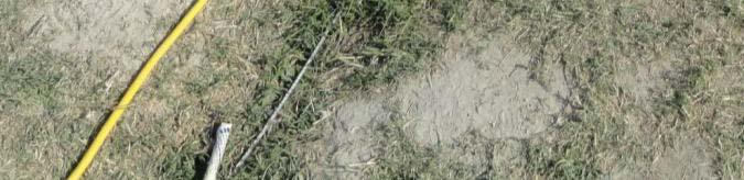
19 THE HOSE CLAMP WILL FAIL AND COME LOOSE, AND THE TWISTED WIRING IS NOT A TIGHT CONNECTION. THIS TYPE OF CONNECTION WILL CAUSE A SOLDIER TO GET AN ELECTRICAL SHOCK OR KILLED. IN THE SHOT AT THE BOTTOM, THERE ARE SEVERAL ISSUES HERE. GROUNDING, FIBRE, AND ELECTRICAL CABLE CANNOT BE CROSSED. THIS TYPE OF HARDWARE CONNECTION DEVICE DOES NOT ACHIEVE THE SAME TIGHT CONNECTION THAT A REGULAR COPPER, BRASS OR BRONZE CONNECTION HARDWARE DEVICE WILL ACHIEVE. THE BONDING JUMPER IS ONLY FOR BONDING NOT MAIN TERMINAL GROUNDING. REFER TO TM &P for the Star Grounding System and the CECOM CECOM TR 98 6 Earth Grounding and Bonding for Tactical Signal Systems.
20 THIS TYPE OF CONNECTION IS NO CONNECTION AT ALL. GROUNDING AND BONDING SHALL NOT CROSS FIBRE AND ELECTRICAL.
21 IN THIS PICTURE, SEVERAL UNITS ARE CONNECTED TO ONEGROUNDINGSYSTEM SYSTEM. THISTYPEOFSETUPISTYPE SETUP DOOMED TO KILL A SOLDIER AND CAUSE MAJOR PROPERTY DAMAGE. THE CABLING CONNECTIONS ARE KNOTTED AND NO CONNECTION DEVICES ARE IN USE. THE STAR GROUNDING SYSTEM IS ZIG ZAGGED RATHER THAN LAIDED IN PER THE TM. THERE IS THE POSSIBILITY AND POTENTIAL FOR STEP POTENTIALS.
Grounding Systems. Equipment Grounding & Grounded Conductors
 Grounding Systems Equipment Grounding & Grounded Conductors Definitions A Grounded or Earthed system is one that is connected to the earth Grounded Conductor is a conductor that normally carries current
GET GROUNDED. Renewable Energy System Grounding Basics
 GET GROUNDED Renewable Energy System ing Basics by Christopher Freitas ASK TEN RENEWABLE ENERGY INSTALLERS ABOUT SYSTEM GROUNDING and you ll likely get ten different opinions as to what the National Electrical
ProTrip Conversion Kits. For GE Types AK-15, AK-25, and AKU- 25 Low-Voltage Power Circuit Breakers INTRODUCTION. DEH Installation Instructions
 DEH 40026 Installation Instructions g ProTrip Conversion Kits For GE Types AK-15, AK-25, and AKU- 25 Low-Voltage Power Circuit Breakers INTRODUCTION GE Conversion Kits are designed for upgrading existing
CAT-1 Series 3. Installation Guide. The Valley Group, Inc. 871 Ethan Allen Hwy. Suite 104 Ridgefield, CT 06877
 CAT-1 Series 3 Installation Guide The Valley Group, Inc. 871 Ethan Allen Hwy. Suite 104 Ridgefield, CT 06877 (203) 431-0262 (203) 431-0296 FAX tvg@cat-1.com Installation of Load Cells for CAT-1 Systems
MECKLENBURG COUNTY. Land Use and Environmental Service Agency Code Enforcement 2/8/12 ELECTRICAL CONSISTENCY MEETING. Code Consistency Questions
 MECKLENBURG COUNTY Land Use and Environmental Service Agency Code Enforcement 2/8/12 ELECTRICAL CONSISTENCY MEETING Code Consistency Questions 1. I am inspecting a building addition. They have a 480V to
INSTALL SERVICE- ENTRANCE SYSTEMS
 SUBCOURSE EN5141 EDITION B US ARMY ENGINEER SCHOOL INSTALL SERVICE- ENTRANCE SYSTEMS INSTALL SERVICE- ENTRANCE SYSTEMS Subcourse Number EN5141 EDITION B United States Army Engineer School Fort Leonard
Earthing UNIT. Learning Objectives. Introduction. To understand purpose of Earthing. To learn system of earthing.
 274 Electrical Technician UNIT 10 Earthing Learning Objectives To understand purpose of Earthing. To learn system of earthing. Introduction The very purpose of earthing is to safe against dangers of shock
INSTRUCTIONS FOR THE RELIANCE CONTROLS ARM SERIES AUTOMATIC TRANSFER SWITCH
 INSTRUCTIONS FOR THE RELIANCE CONTROLS ARM SERIES AUTOMATIC TRANSFER SWITCH THE RELIANCE CONTROLS ARM SERIES AUTOMATIC TRANSFER SWITCH IS NOT FOR "DO-IT-YOURSELF" INSTALLATION. It must be installed by
UPPCO SERVICE MANUAL
 Revised 01/2015 Section 6 ELECTRIC SERVICE - GENERAL Page 1 of 10 Section 6 Electric Service - General 6-1 Number of Services and Voltages / Meter... 2 6-2 Energy Conversion Factors... 7 6-3 Lightning
INSPECTOR LINE LOAD SIMULATOR INSTRUCTION MANUAL TASCO, INC.
 INSPECTOR LINE LOAD SIMULATOR INSTRUCTION MANUAL INS120P TASCO, INC. THIS TESTER IS DESIGNED FOR USE ONLY BY QUALIFIED ELECTRICIANS. IMPORTANT SAFETY WARNINGS mwarning Read and understand this material
INDUSTRY WIDE LABOR-MANAGEMENT SAFETY COMMITTEE
 INDUSTRY WIDE LABOR-MANAGEMENT SAFETY COMMITTEE SAFETY BULLETIN #23 GUIDELINES FOR WORKING WITH LIGHTING SYSTEMS AND OTHER ELECTRICAL EQUIPMENT All electrical systems and electrically energized equipment
CONNECTING INVERTER. by John Wiles
 connecting CONNECTING the inverter THE INVERTER by John Wiles 10 IAEI NEWS September.October 2009 www.iaei.org Connecting the utility-interactive inverter properly is critical to the safe, long-term and
SINGLE PHASE WIRING SPECIFICATIONS
 SINGLE PHASE WIRING SPECIFICATIONS 1-866-MEC-ELEC (1-866-632-3532) Office Locations: Hondo Office 237 Hwy 173 N Hondo, TX 78661-0370 Fax 830.426.3335 Dilley Office 1718 W. FM 117 Dilley, TX 78017 Fax 830.965.1425
4" ENVIRONMENTAL E-SERIES PUMPS OWNER'S MANUAL. DANGER warns about hazards that will cause. WARNING warns about hazards that can cause
 4" ENVIRONMENTAL E-SERIES PUMPS OWNER'S MANUAL BEFORE INSTALLING PUMP, BE SURE TO READ THIS OWNER S MANUAL CAREFULLY. CAUTION Fill pump with water before starting or pump will be damaged. The motor on
THREE PHASE WIRING SPECIFICATIONS
 THREE PHASE WIRING SPECIFICATIONS 1-866-MEC-ELEC (1-866-632-3532) Office Locations: Hondo Office 237 Hwy 173 N Hondo, TX 78661-0370 Fax 830.426.3335 Dilley Office 1718 W. FM 117 Dilley, TX 78017 Fax 830.965.1425
TEMPORARY ELECTRIC WIRING FOR CARNIVALS, CONVENTIONS, EXHIBITIONS, FAIRS AND SIMILAR USES
 INFORMATION BULLETIN / PUBLIC - ELECTRICAL CODE REFERENCE NO.: LAMC 93.0230 Effective: 3-24-69 DOCUMENT NO. P/EC 2002-006 Revised: 11-17-00 Previously Issued As: RGA #7-69 TEMPORARY ELECTRIC WIRING FOR
Unit 3 Lesson 3 Electric Circuits. Copyright Houghton Mifflin Harcourt Publishing Company
 A Complete Circuit What are the parts of an electric circuit? An electric circuit is a complete, closed path through which electric charges can flow. All electric circuits contain three basic parts: an
AUTOMATIC DUST COLLECTION FOR SMALL SHOPS INSTRUCTIONS GG500B MOTOR CONTACTOR WITH THERMAL PROTECTION 115VAC COIL
 AUTOMATIC DUST COLLECTION FOR SMALL SHOPS INSTRUCTIONS GG500B MOTOR CONTACTOR WITH THERMAL PROTECTION 115VAC COIL Thank you for choosing our Automatic Dust Collection System. We at Grngate have developed
WARNING WARNING WARNING. Warnings and Cautions MOVING PARTS ENTANGLEMENT HAZARD CHEMICAL AND FIRE HAZARD FALLING OR CRUSHING HAZARD
 Warnings and Cautions As you read these instructions, you will see S, S, NOTICES and NOTES. Each message has a specific purpose. S are safety messages that indicate a potentially hazardous situation, which,
Understanding RV Electrical Hazards. Do you really want to plug in here?
 Understanding RV Electrical Hazards Do you really want to plug in here? John Slaughter RV owner for 12 years, 150,000 miles of travel. Electrical Engineer Full disclosure, I am not a safety expert. Takeaways
MASTERsine Inverter PXA Series Installation Guide
 Backup Power System Expert TM MASTERsine Inverter PXA Series Installation Guide Important Safety Instructions IMPORTANT: Read and save this Installation Guide for future reference. This chapter contains
ATV/UTV WINCH INSTRUCTION BOOK 3000 LBS
 ATV/UTV WINCH INSTRUCTION BOOK 3000 LBS As you read these instructions, you will see WARNINGS and CAUTIONS. Each message has a specific purpose. WARNINGS and CAUTIONS identify the hazard, indicate how
Installation Instructions for Lighthouse SS Power Pedestal Rev. 3 5/20/14
 Installation Instructions for Lighthouse SS Power Pedestal Rev. 3 5/20/14 Hazardous voltage. Can cause severe injury or death. Turn off main power before opening panel. Eaton Electrical Inc. strongly recommends
Electrical Safety. Introduction
 Electrical Safety Introduction Electrical hazards 300 electrocutions every year in the U.S. Leading cause is insufficient training ALL were preventable What is Electricity? How Electricity Works Created
Model 579 Curtain Machine Manual. General Information. Unpacking:
 Model 579 Curtain Machine Manual. General Information The Model 579 curtain machine is designed for use with most light duty commercial and residential drapery tracks. The 579 curtain machine is designed
Electrical Safety. Electricity. Safety. Division of Workers Compensation HS01-013B(02-14)
") Electrical Safety Electricity Safety Division of Workers Compensation HS01-013B(02-14) Table of Content Respect The Power Of Electricity 3 Inform Your Supervisor Of Faulty Equipment 3 Wear Protective Clothing
Electrical Safety Electricity Safety Division of Workers Compensation HS01-013B(02-14) Table of Content Respect The Power Of Electricity 3 Inform Your Supervisor Of Faulty Equipment 3 Wear Protective Clothing
ACC Series Power Conditioner OPERATION & INSTALLATION MANUAL
 ACC Series Power Conditioner OPERATION & INSTALLATION MANUAL PHASETEC digital power conditioners are designed to safely operate electrical equipment in the harshest power quality environments. With a wide
Electrical Hazard Three factors determine the resistance of a substance to the flow of electricity: conductors insulators extreme caution
 Electrical Safety Electrical Hazard Three factors determine the resistance of a substance to the flow of electricity: What it is made of. Its size. Its temperature. Substances with very little resistance
Bayside Model BU2050 Installation, Maintenance, and Operation Manual
 Bayside Model BU2050 Installation, Maintenance, and Operation Manual 000000 000000 Marina Electrical Equipment, Inc. 100 Warwick Court Williamsburg, VA 23185 Toll Free: 1-855-258-3939 Fax: 1-757-258-3988
ELECTRICAL GROUNDING SAFETY PROGRAM
 ELECTRICAL GROUNDING SAFETY PROGRAM PURPOSE / SCOPE The purpose of this program is to ensure the proper installation, maintenance, inspection, and testing of equipment grounding conductors on construction
AUTOMATIC DUST COLLECTION FOR SMALL SHOPS INSTRUCTIONS GG500C MOTOR CONTACTOR WITH THERMAL PROTECTION 220VAC COIL
 AUTOMATIC DUST COLLECTION FOR SMALL SHOPS INSTRUCTIONS GG500C MOTOR CONTACTOR WITH THERMAL PROTECTION 220VAC COIL Thank you for choosing our Automatic Dust Collection System. We at Grngate have developed
9/16/2010. Chapter , The McGraw-Hill Companies, Inc. TRANSMISSION SYSTEMS. 2010, The McGraw-Hill Companies, Inc.
 Chapter 3 TRANSMISSION SYSTEMS 1 Transmitting large amounts of electric energy over long distances is accomplished most efficiently by using high-voltages. Without transformers the widespread distribution
Electrical Installation
 Electrical Installation Symmetra LX Tower UPS Models 200 V, 4-8 kva 208/240 V, 4-8 kva 220/230/240 V, 4-8 kva 200 V, 4-16 kva 208/240 V, 4-16 kva 220/230/240 V, 4-16 kva Important Safety Messages SAVE
Choosing Household Wiring for Low EMF
 Choosing Household Wiring for Low EMF from left to right: ROMEX 12/2, ROMEX 12/3, EMT conduit, IMC conduit, MC 12/2 Modern buildings have electrical wiring in all walls, and often in ceilings and under
Safety and General Information
 Safety and General Information Symmetra LX Tower Rack-Mount UPS Models 200 V, 4-8 kva 208/240 V, 4-8 kva 220/230/240 V, 4-8 kva 200 V, 4-16 kva 208/240 V, 4-16 kva 220/230/240 V, 4-16 kva Important Safety
Installation, Maintenance, and Operation Manual
 GTX TM UNIT SUBSTATION Installation, Maintenance, and Operation Manual Rev.3 03-10-15 Marina Electrical Equipment, Inc. 100 Warwick Court Williamsburg, VA 23185 Toll Free: 1-855-258-3939 Fax: 1-757-258-3988
FACT SHEET Standard: Electrical Safety
 What is a Ground Fault Circuit Interrupter? FACT SHEET The ground-fault circuit interrupter, or GFCI, is a fast-acting circuit breaker designed to shut off electric power in the event of a ground-fault
Earth-Rite MGV Mobile Grounding Verification. White Paper. Author Details: Page 1 of 5
 White Paper Author Details: Mike O Brien, Head of Marketing and Sales for Newson Gale If you have any questions relating to the topics discussed in this article, you can contact Mike directly at: mike.obrien@hoerbiger.com
WINCHMAX. Hydraulic Winch Instructions b b b
 WINCHMAX Hydraulic Winch Instructions 1010001b 1510001b 2010001b Safety warnings and precautions WARNING: When using the tool, basic safety precautions should always be followed to reduce the risk of personal
Installation Instructions for Admiral Power Pedestal (# )
") Installation Instructions for Admiral Power Pedestal (#70-8643) Hazardous voltage. Can cause severe injury or death. Turn off main power before opening panel. Eaton Electrical Inc. strongly recommends
Installation Instructions for Admiral Power Pedestal (#70-8643) Hazardous voltage. Can cause severe injury or death. Turn off main power before opening panel. Eaton Electrical Inc. strongly recommends
PRODUCT MANUAL TILE CUTTING MACHINE. . Operation. Parts List and Diagram SPECIFICATIONS CAUTION:
 FLORCRAFTT TM PRODUCT MANUAL SKU NUMBER 709-4242 SERIAL NUMBER: CAUTION: FOR YOUR OWN SAFETY READ INSTRUCTION MANUAL COMPLETELY AND CAREFULLY BEFORE OPERATING THIS 7 TILECUTTING MACHINE SPECIFICATIONS
SECTION 15. GROUNDING AND BONDING
 9/27/01 AC 43.13-1B CHG 1 SECTION 15. GROUNDING AND BONDING 11-185. GENERAL. One of the more important factors in the design and maintenance of aircraft electrical systems is proper bonding and grounding.
Installation Manual CS9300-LED. Professional Series Landscape Lighting System
 Installation Manual CS9300-LED Professional Series Landscape Lighting System CS9300 Professional Series LED Landscape Lighting System pg. 1 READ THESE INSTRUCTIONS ENTIRELY BEFORE BEGINNING INSTALLATION!
Installation and Construction Notes for EVSE4
 Installation and Construction Notes for EVSE4 You need to read and understand this if you want to build an EVSE that will be safe and need to pass a building inspectors review. Before beginning this process
PHOTOVOLTAIC ELECTRICAL POWER SYSTEMS INSPECTOR/INSTALLER CHECKLIST
 PHOTOVOLTAIC ELECTRICAL POWER SYSTEMS INSPECTOR/INSTALLER CHECKLIST The following checklist is an outline of the general requirements found in the 2005 National Electrical Code (NEC) Article 690 for Photovoltaic
Electricity. Chapter 20
 Electricity Chapter 20 Types of electric charge Protons + charge Electrons - charge SI unit of electric charge is the coulomb (C) Interactions between charges Like charges repel Opposite charges attract
3.8 KVA IsoG2. INSTALLATION INSTRUCTIONS & OWNER S MANUAL Model 93-ISOG2/8-A LT-ISOG28-1. Issue 1 Print 3 SHORELINE ISOLATION TRANSFORMER
 Issue 1 Print 3 3.8 KVA IsoG2 SHORELINE ISOLATION TRANSFORMER LT-ISOG28-1 INSTALLATION INSTRUCTIONS & OWNER S MANUAL Model 93-ISOG2/8-A Charles Industries, Ltd. All rights reserved. Printed in the United
Ladders. Meeting Objectives. Introduction/Overview. General Hazards. OSHA Regulations and Frequent Violations
 Ladders Meeting Objectives To explain the proper selection, use, and maintenance of portable ladders. The result should be closer inspection of ladders and greater awareness of how to use them safely.
Model Numbers SAVI-NOTE75, SAVI-NOTE150
 Installation INSTRUCTIONS & OWNERS Manual SAVI NOTE UNDERWATER LED LIGHT Model Numbers SAVI-NOTE75, SAVI-NOTE150 Safety Precautions...2 SAVI Note Install Instructions...3-4 1 READ AND FOLLOW ALL INSTRUCTIONS
Construction and Wiring Guidelines for Ergon Energy Substation Panels
 Construction and Wiring Guidelines for Ergon Energy Substation Panels Table of Contents Purpose and Scope... 1 Responsibilities... 1 Definitions, Abbreviations and Acronyms... 1 References... 1 Panel Wiring...
WARNING WARNING CAUTION. Warnings and Cautions MOVING PARTS ENTANGLEMENT HAZARD MOVING PARTS ENTANGLEMENT HAZARD CHEMICAL AND FIRE HAZARD
 Warnings and Cautions As you read these instructions, you will see S, S, NOTICES and NOTES. Each message has a specific purpose. S are safety messages that indicate a potentially hazardous situation, which,
SECTION LOW VOLTAGE DISTRIBUTION EQUIPMENT
 SECTION 16400 LOW VOLTAGE DISTRIBUTION EQUIPMENT A. General 1. The University does not accept Series-Rated equipment for power distribution switchboards, distribution panels and branch circuit panelboards.
PORTABLE CORRAL KIT INSTALLATION INSTRUCTIONS
 Part No. PLK-1 PORTABLE CORRAL KIT INSTALLATION INSTRUCTIONS The Power Wizard Portable Corral Kit features the PW350B Electric Fence Energizer. This battery-operated energizer is capable of powering about
1. Cranes. 3. Hazardous Chemicals. 4. Signs. 2. Trenching and Excavations
 A Safe Operation Safety Tips for Heavy Construction 1. Cranes Cranes are a common piece of equipment on heavy construction jobsites. Always perform a walk around inspection before and after each shift
Service Entrance Methods
 Service Section Typical switchboards consist of a service section, also referred to as the main section, and one or more distribution sections. The service section can be fed directly from the utility
OWNER S MANUAL SELF-PRIMING PORTABLE UTILITY PUMP
 Model 54011-0 OWNER S MANUAL SELF-PRIMING PORTABLE UTILITY PUMP Questions, problems, missing parts? Before returning to the store call AQUAPRO Customer Service 8 a.m. - 5 p.m., EST, Monday-Friday 1-844-242-2475
2011/2008/2005 NATIONAL ELECTRICAL CODE SOLAR PV CODE COMPLIANCE REFERENCE
 2011/2008/2005 NATIONAL ELECTRICAL CODE SOLAR PV CODE COMPLIANCE REFERENCE PAGE 1 OF 5 This Reference provides a very comprehensive list of aspects of a solar PV installation that could be reviewed, clarifying
Product Manual MNX10015 / REV B MODEL SB142, SB242. Dual Output Series Switch Boxes
 Product Manual MNX10015 / REV B MODEL SB142, SB242 Dual Output Series Switch Boxes Contents Section I Overview Introduction.... 2 Description... 2 Section II Installation Mounting... 3 Electrical Connections...
Electrostatic System Checks
 Instruction Sheet P/N Electrostatic System s WARNING: Allow only qualified personnel to perform the following tasks. Follow the safety instructions in this document and all other related documentation.
Arnberg Industries & It s Partners are not responsible for any damage or injury caused by correct or incorrect installation of this transfer switch.
 3560 NE ROZENE WAY BREMERTON, WASHINGTON 98311 (530) 316-1049 Generator Transfer Switch Model; HTS15-MAN & HTS15-MAN-2 Tools Needed For Installation Power drill Wire stripper and cutter (10 to 14 gauge)
Installation Manual. CS9300 Professional Series Landscape Lighting System
 Installation Manual CS9300 Professional Series Landscape Lighting System CS9300 Professional Series Landscape Lighting System pg. 1 READ THESE INSTRUCTIONS ENTIRELY BEFORE BEGINNING INSTALLATION! Congratulations
Patriot Portable Material Hoist 850/1000/2000. Operator s Manual
 Patriot Portable Material Hoist 850/1000/2000 Operator s Manual Manual must be read carefully by all operators before hoist is set-up and used. Failure to follow all directions and warnings for safe mounting
Electrical Safety. Electrical Safety Webinar. Electrical. Printing Industries Alliance Printing Industries Alliance 1
 Webinar 1 Electrical 2 1 Webinar Introduction An average of one worker is electrocuted on the job every day There are four main types of electrical injuries: Electrocution (death due to electrical shock)
SECTION 1: Field Inspection Guide for Rooftop Photovoltaic (PV) Systems
 Systems") COUNTY OF SANTA CRUZ PLANNING DEPARTMENT 701 OCEAN STREET, 4 th FLOOR, SANTA CRUZ, CA 95060 (831) 454-2580 FAX: (831) 454-2131 TDD: (831) 454-2123 KATHLEEN MOLLOY PREVISICH, PLANNING DIRECTOR Photovoltaic
COUNTY OF SANTA CRUZ PLANNING DEPARTMENT 701 OCEAN STREET, 4 th FLOOR, SANTA CRUZ, CA 95060 (831) 454-2580 FAX: (831) 454-2131 TDD: (831) 454-2123 KATHLEEN MOLLOY PREVISICH, PLANNING DIRECTOR Photovoltaic
INSTALL CIRCUIT PROTECTIVE DEVICES
 SUBCOURSE EN5146 EDITION B US ARMY ENGINEER CENTER AND SCHOOL INSTALL CIRCUIT PROTECTIVE DEVICES INSTALL CIRCUIT PROTECTIVE DEVICES Subcourse Number EN5146 EDITION B United States Army Engineer School
120-ELECTRICAL SAFETY PROGRAM
 120.1 PURPOSE A. To set forth procedures for the safe use of electrical equipment, tools, and appliances at Central New Mexico Community College (CNM). 120.2 SCOPE A. This program applies to all CNM employees
Installation Instructions
 K-Series Constant-Wattage Heating Cable Installation Instructions Read and understand this material before installing this heater. Failure to understand how to safely install the heater could result in
4 Electric Circuits. TAKE A LOOK 2. Identify Below each switch, label the circuit as a closed circuit or an open circuit.
 CHAPTER 17 4 Electric Circuits SECTION Introduction to Electricity BEFORE YOU READ After you read this section, you should be able to answer these questions: What are the three main parts of a circuit?
LED AC DRIVERLESS FLOODLIGHTS WITH PIR FOR MODEL: FLAC10BPIR, FLAC20BPIR, FLAC30BPIR & FLAC50BPIR
 INTRODUCTION The LED AC Driverless Floodlights with PIR include a hanging / mounting bracket and a 100cm cable. SPECIFICATION LED 800-4000lm IP65 180-240V IK07 6000K 50Hz >80 Ra 10W- 50W Dimensions: FLAC10BPIR:
NEW SERVICE HANDBOOK COMMERCIAL & IRRIGATION SUPPLEMENT
 NEW SERVICE HANDBOOK COMMERCIAL & IRRIGATION SUPPLEMENT Meter Installations There are three basic ways to measure electricity consumption: Small and medium services are metered directly using direct connect
SERVICE GUIDE For WARN PULLZALL 120Vac P/N &
 SERVICE GUIDE For WARN PULLZALL 120Vac P/N 885000 & 885001 REPAIR / REPLACEMENT INSTRUCTIONS TROUBLE SHOOTING GUIDE 987604A2.doc Page 1 of 48 WARNING This guide identifies potential hazards and has important
LPE C5 Battery Relocation Kit
 LPE C5 Battery Relocation Kit The LPE C5 Corvette battery relocation kit improves vehicle weight distribution by moving weight to the rear of the vehicle. The improved weight distribution increases traction
HANDLING OF ASSEMBLY... 1 RRH END OF ASSEMBLY... 1 BASE STATION END OF ASSEMBLY... 7 POWER CODING REVISION HISTORY... 11
 INSTALLATION MANUAL HUBER+SUHNER AG Fiber Optics DOC-0000807936 Rev A February 07, 2018 Page 1 of 11 Table of contents HANDLING OF ASSEMBLY... 1 RRH END OF ASSEMBLY... 1 BASE STATION END OF ASSEMBLY...
Microinverters and AC PV modules are becoming. Microinverters and AC PV Modules. Different Beasts. Perspectives on PV.
 Perspectives on PV Microinverters and AC PV Modules Are Different Beasts by John Wiles Microinverters and AC PV modules are becoming very common in residential and small commercial PV systems. See photos
Surface Regulations and Policies
 Surface Regulations and Policies COAL FATALITIES 1970-2002 350 300 250 200 150 100 50 0 1970 1973 1976 1979 1982 1985 1988 1991 1994 1997 2000 From January 1, 1970 through today, a total of 240 coal miners
 CENTRIFLOW METER and ELECTRONICS WIRING and INSTALLATION MANUAL REV 01/16 ORIGINAL LANGUAGE Copyright 2016 Eastern Instrument Laboratories, Inc. All Rights Reserved. TABLE OF CONTENTS SAFETY Safe Operation...
Raychem CSJA Safety Instructions. Safety Instructions. Customer Service. Kit Contents. Installation Instructions
 Raychem CSJA 1521 Cold-Shrinkable Splice for single core polymeric insulated (XLPE-EPR) cables up to 15kV for tape, wire, Unishield, LC shield, JCN, and flat strap neutral cable UniShield is a trademark
Sentinel Field Satellite Controller Metal Pedestal, Plastic Pedestal and Wall Mount Models Installation Instructions
 WARNING HIGH VOLTAGE 115V 4 M AP Sentinel Field Satellite Controller Metal Pedestal, Plastic Pedestal and Wall Mount Models Installation Instructions Important: For your protection and the safety of the
Dual-Lite Trident TRF 40 Wide Battery Cabinet 20-40kVA Systems USER MANUAL
 Dual-Lite Trident TRF 40 Wide Battery Cabinet 20-40kVA Systems USER MANUAL 755-00020-DL 5/17/2017 2 755-00020-OEM R01 TABLE OF CONTENTS 1. Important Information About This Manual... 4 1.1 Manual Symbols...
Transmission & Distribution Glossary of Electrical Terms
 Transmission & Distribution Glossary of Electrical s Breaker Panel Bushing Circuit Circuit Breaker Conductor Conduit Consumption Current Distribution Electricity (Static vs. Current) Electron Feeder The
CALTRAP INSTALLATION AND OPERATIONS MANUAL
 INSTALLATION AND OPERATIONS MANUAL NOTE Please read this entire installation and operations manual before energizing the. Safety Considerations: Installing and servicing capacitor equipment can be hazardous.
Section 02: Pre-Installation Procedures
 Section 02: Pre-Installation Procedures Foundation! WARNING The MUST be placed on a surface that will support the combined weight of the, options, fixtures, and tooling, etc. (refer to the Specifications
AE012 Enclosure for E5x Series Energy Meters With Swing Panel Kit Product Overview
 RoHS Compliant Pictured with the E5x meter installed. E5x meter and enclosure are purchased separately. DANGER HAZARD OF ELECTRIC SHOCK, EXPLOSION, OR ARC FLASH Follow safe electrical work practices. See
SX-16 Nightsun Searchlight Safety and Service Bulletin # SL
 SX-16 Nightsun Searchlight Safety and Service Bulletin # SL 0898-02 Issue Date: 09/25/98 Amended Date: 02/09/06 Subject: SX-16 Nightsun Junction Box Wiring Modification Affected Products: All SX-16 Nightsun
HP BladeSystem c7000 Carrier-Grade Options Installation Guide
 HP BladeSystem c7000 Carrier-Grade Options Installation Guide Part Number 5991-8062 September 2009 (Second Edition) Copyright 2009 Hewlett-Packard Development Company, L.P. The information contained herein
Galaxy VM. Battery Breaker Box Installation 09/
 Galaxy VM Battery Breaker Box Installation 09/2016 www.schneider-electric.com Legal Information The Schneider Electric brand and any registered trademarks of Schneider Electric Industries SAS referred
Application Note EMC - Checklist
 Application Note EMC - Checklist A checklist to avoid EMC trouble General 100151 Title... EMC - Checklist Version... 1.10 Document no.... 100151 Original...en Author... Festo Last saved... 08.08.2017 Copyright
ELECTRICAL. 60 Minutes
 ELECTRICAL 60 Minutes AGENDA Electrical definitions Electrical shocks, burns and secondary injuries Electrical hazards in the workplace Safety devices and prevention steps Do s and Don ts INTRODUCTORY
Quick Start Guide TS 910
 Quick Start Guide TS 910 DANGER HAZARD OF ELECTRICAL SHOCK, EXPLOSION, OR ARC FLASH Read and understand this quick start guide before installing and operating the transfer switch The installer is responsible
ELECTRO-MECH SCOREBOARD CO.
 ELECTRO-MECH SCOREBOARD CO. MM-338 FOOTBALL SCOREBOARD OWNER S HANDBOOK Thank you for choosing an Electro-Mech Scoreboard for your athletic complex. We are confident that your new scoreboard will give
INSTALLATION, OPERATION AND MAINTENANCE INSTRUCTIONS FOR NEW YORK 18 WATT SERIES
 INSTALLATION, OPERATION AND MAINTENANCE INSTRUCTIONS FOR NEW YORK 18 WATT SERIES IMPORTANT SAFEGUARDS When using electrical equipment, basic safety precautions should always be followed including the following:
TRANSMISSION SYSTEMS
 TRANSMISSION SYSTEMS Transmitting large amounts of electric energy over long distances is accomplished most efficiently by using high-voltages. Without transformers the widespread distribution of electric
OPERATING INSTRUCTION
 11/05 Form #273 OPERATING INSTRUCTION MODEL 4105 Disital Earth Resistance Tester 2150 joshua's Path, Suite 302, Hauppauge, NY 11788 Phone : 1-800-645-5398 or 1-639-231-7050 Fax : 1-639-434-3128 E-mail
RECESSED TRACK (120V) SPECIFICATIONS
 SPECIFICATIONS") RECESSED TRACK (120V) SPECIFICATIONS GENERAL Recessed track shall be approved by the NEC for flush-mounting into ceiling or any flat surface. Recessed Track shall allow fixtures to be easily focused, switched,
RECESSED TRACK (120V) SPECIFICATIONS GENERAL Recessed track shall be approved by the NEC for flush-mounting into ceiling or any flat surface. Recessed Track shall allow fixtures to be easily focused, switched,
! WARNING! WARNING. Dock Boxes Unlimited, Inc. strongly recommends that these products be installed by a qualified electrician.
 Coming together is a beginning. Keeping together is progress. Working together is success. Installation Instructions for the Hatteras Light Power Pedestal (#70-8631)! DANGER! WARNING! WARNING Hazardous
Learning Module 10: Loadcenters. 101 Basic Series
 Learning Module 10: Loadcenters 101 Basic Series What You Will Learn We ll step through each of these topics in detail: What Does a Loadcenter Do? 4 Applications 4 Basic Circuitry and Wiring 5 Residential
Basic Electrical Safety
 Basic Electrical Safety Concerned About Electricity? How many sets of holiday lights do you plug into one extension cord? Do you still use your hot and sparking electric drill? Is your vacuum cleaner s
What is electricity? A form of energy that is carried through wires and is used to operate machines, lights, etc. PPT-SM-ES
 Electrical Safety What is electricity? A form of energy that is carried through wires and is used to operate machines, lights, etc. PPT-SM-ES 2015 2 There are two forms of electricity Static electricity
Installation Manual CS9100-LED. Professional Series Landscape Lighting System
 Installation Manual CS9100-LED Professional Series Landscape Lighting System LED Landscape Lighting System pg. 1 READ THESE INSTRUCTIONS ENTIRELY BEFORE BEGINNING INSTALLATION! Congratulations on your
BLACKBIRD WIRING MANUAL
 BLACKBIRD WIRING MANUAL VERSION ZX120 5/09 TO BE USED IN CONJUNCTION WITH A VEHICLE-SPECIFIC INSTALLATION SUPPLEMENT System Capabilities The 5kW Blackbird will provide 42 amperes of 120 Volt alternating