Gears Introduction. Herbert S. Cheng Introduction 29.2 Gear Types Spur Gears Helical Gears Bevel and Hypoid Gears Worm Gears
|
|
|
- Opal Sharp
- 6 years ago
- Views:
Transcription
1 29 Gears Herbert S. Cheng Northwestern University 29.1 Introduction 29.2 Gear Types Spur Gears Helical Gears Bevel and Hypoid Gears Worm Gears 29.3 Tribological Failure Modes Macro-pitting (Spalling) Micro-pitting (Gray Staining) Scuffing Mild Wear 29.4 Full-Film Lubrication Performance Spur Gears Helical Gears Spiral Bevel and Hypoid Gears Worm Gears 29.5 Mixed Lubrication Characteristics Asperity Contact Pressure Full Simulation of Asperity Contact and Fluid Film Pressure A Macro Micro Approach to Mixed Lubrication Asperity Contact Temperature 29.6 Modeling of Tribological Failures in Gears Conventional Pitting Life Model Prospective Pitting Life Model Conventional Scuffing Model Prospective Scuffing Model Wear Modeling in Spur Gears 29.7 Failure Tests 29.8 Conclusions 29.1 Introduction Gear teeth contacts have been recognized as one of the most complicated applications of tribology. In an earlier review (Radovich, 1984) on gear lubrication, it was pointed out that despite the extensive research in gear lubrication, it has not been possible to reduce the art of gear lubrication to a science. There is no good substitute for practical experience in gear design. This situation is gradually changing, mainly due to rapid developments in elastohydrodynamic lubrication (EHL) and the effects on gear tribological failures. Dudley (1980) provided extensive coverage on how the relation between the pitting initiation life and contact stresses improves as the regime of lubrication or the EHL film changes from boundary to mixed and finally to full film lubrication. In each regime, Dudley proposed a different empirical exponent to relate the contact stress and fatigue life. This relation was also suggested by Kubo et al. (1991) in their review of gear lubrication. They also contributed a chart for determining the regime of lubrication when the EHL film thickness and the gear teeth surface roughness are known. It is widely recognized that gear scuffing is most strongly related to the flash temperature in a sliding gear contact. When it exceeds the critical temperature of the lubricant, scuffing is initiated. Most present scuffing predictive models are based on this argument. Kubo et al. (1991) compiled an excellent list of the present major scuffing models, from the well-known Blok-Kelly s flash temperature formula to the complicated ISO proposal for estimating the scuffing load.
2 The current models for predicting gear tribological failures have been reviewed quite thoroughly in recent literature. It is not the intent here to add merely another updated review. Rather, the objectives here are to review recent research on EHL and tribological failures related to gear lubrication, pitting, scuffing, and wear, and to delineate future prospects in developing more advanced predictive pitting and scuffing models for gears Gear Types Among the many gear types, the most commonly used ones are spur, helical, bevel, and worm gears. The lubrication process and lubrication-related failures in these gears have a great deal in common because the loads in these gears are all transmitted through Hertzian lubricated contacts known as elastohydrodynamic (EHL) contacts. A brief description is given as to the geometry and operation of these gears Spur Gears Geometrically, spur gears are the simplest of all gears. They are perhaps the most commonly used gears in general applications. The spur teeth are parallel to the shaft and transmit motion and power between two parallel shafts, as shown in Figure Except for some very special cases where extremely accurate motion is required, the tooth shape of most spur gears is of the involute form because of its tolerance to any change of center distance and ease of manufacture. Figure 29.2 shows a pair of spur gear teeth beginning to contact at point K 2 at the tip of the driven gear. The force is transmitted along the line of action AB, which is tangent to both base circles and is inclined at an angle φ, known as the pressure angle, from the common tangent of the two pitch circles. The contact force always acts along the path of action during the entire engagement. At the beginning of the contact between one pair of teeth, there is FIGURE 29.1 Spur gears. usually a preceding pair in contact, shown at K 1, at a distance p cosφ away from K 2, where p is the circular pitch of the gears. Just prior to contact at K 2, the preceding pair takes the full load. As soon as the contact begins, the load is shared between the two pairs. Before the advent of EHL, the lubrication process in gear teeth contacts was only understood qualitatively. With the rapid development of EHL, the lubrication characteristics for spur gears can now be quantified either by line contact EHL analyses for straight spur gears or by point contact EHL analyses for gears with axially modified profiles. Further discussion is given later in the section on lubrication performance of spur gears Helical Gears Like spur gears, helical gears are usually employed to transmit motion between two parallel shafts. In helical gears, the teeth are cut at an angle to the shaft axis, known as the helix angle, ψ, as shown in Figure 29.3 for a double-row-helical or herringbone gear. This arrangement allows helical gears to have more pairs of teeth in contact during the engagement compared to spur gears. It usually runs more quietly and has less vibration. The disadvantage of single-row-helical gears is that the tooth load includes a thrust component, requiring larger supporting bearings for the shaft and complicating bearing selection in that thrust loads must be supported. The contact pattern on the tooth face is not a line or elliptical contact with the major axis parallel to the shaft axis as in the case of spur gears. Instead, the major axis of the contact is now inclined to the shaft axis. The length of the major axis also changes during the engagement as it traverses from the root to the tip of the facing. The lubrication characteristics of helical gears will be described later in this chapter.

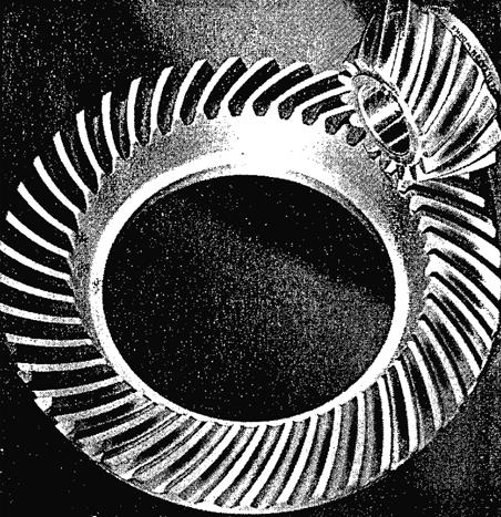
3 FIGURE 29.2 Load sharing between two spur-gear contacts Bevel and Hypoid Gears Bevel gears are used to transmit motion between two non-parallel, usually orthogonal, co-planar intersecting shafts. If the bevel gear teeth are cut straight, they are called straight bevel gears, as shown in Figure If the teeth are cut curved with a zero spiral angle in the mid-section, as shown in Figure 29.5, they are called zerol bevel gears. For bevel teeth that are cut along a spiral path, they are known as spiral bevel gears. Spiral bevel gears can carry a higher load capacity and run more quietly than other types of bevel gears. Figure 29.6 shows a typical spiral bevel gear. Hypoid gears are used for transmitting motion between two non-intersecting orthogonal shafts. Their tooth form resembles that of the spiral bevel except the pinion shaft is offset either above or below the gear shaft, as shown in Figure Double-helical (herring- FIGURE 29.3 bone) gears Worm Gears Worm gears are primarily intended for transmitting motion between two-intersecting orthogonal shafts similar to hypoid bevel gears. However, the geometries of these two systems are very different. The driving member is a cylindrical worm resembling a screw, and it meshes with basically a helical gear. The speed ratio of worm gear sets can be large and the sliding can be very high. For this reason, worm gears are used mostly for light loads. Figure 29.8 shows a typical worm gear set Tribological Failure Modes There are at least four major modes of gear tooth failure that are directly related to deterioration of lubrication or change of lubrication performance in gear tooth contact such as loss of lubricant film thickness, rapid increase in contact temperature, and excessive foreign particles in the lubricant. These


4 FIGURE 29.4 Straight bevel gears. FIGURE 29.5 Zerol bevel gears. FIGURE 29.6 Spiral bevel gears.
 Macro-pits can appear almost anywhere on the tooth facing.")
. These pits can have dimensions comparable to Hertzian contact size.")
5 FIGURE 29.7 Hypoid gears. FIGURE 29.8 Worm gears. failure modes include macro-pitting or spalling; micro-pitting or gray staining; scuffing; and mild wear. Brief discussions are given as to the characteristics and some possible mechanisms of these failure modes Macro-pitting (Spalling) Macro-pits can appear almost anywhere on the tooth facing. However, they are primarily found near the pitch line of spur and helical gears. Some of these pits have shapes like a shell. Figure 29.9 depicts such a spall located slightly above the pitch line of a helical gear (Dudley, 1980). These pits can have dimensions comparable to Hertzian contact size. They can originate on the surface due to intensified stresses around large asperity contacts or surface defects such as nicks and furrows. Also, they can be subsurface initiated from a material inclusion, as in the classical case of subsurface fatigue in rolling bearings and lubricated rollers. For subsurface macro-pitting, lubrication does not have a strong effect. It is more strongly influenced by the size, density, and material characteristics of the inclusions. Surface initiated macro-pitting is strongly related to lubrication because it strongly affects the intensity of the near-surface stresses Micro-pitting (Gray Staining) FIGURE 29.9 Pitting of case-hardened pinion. When lubrication deteriorates in gear teeth contacts, the load is borne mainly by the asperity contacts. Under this condition, the mode of failure often shifts from macro-pitting to micro-pitting, particularly for high-quality or nearly inclusion-free materials. Micro-pitting is caused by rapid propagation of groups of cracks induced by multiple asperity contacts. These shallow pits are small in the micron range but cover a wide area, resulting in grayish patches. For this reason, they have often been referred to as gray staining or sometimes as frosting. Dudley (1980) showed a typical frosting appearance of micro-pitting on a high speed case carburized gear; it is reproduced here in Figure Micro-pitting can be a slow progressive degeneration and is often considered to be nondestructive unless it leads to larger sized macro-pits Scuffing When there is substantial sliding between a lubricated rolling contact, excessive temperature at the sliding asperity contacts can cause all protective lubricating films to break down. The softer asperities can deform


6 FIGURE Micro-pitting (frosting) on a high-speed carburized gear. FIGURE Typical scuffing failure in gears. plastically and transfer to the mating surface. This is usually accompanied by a rapid increase in wear rate or even seizing of the sliding pair. This phenomenon is known as scuffing, which in severe cases can lead to seizure. In gear tooth contacts, scuffing can occur in the contacting areas wherever the slide-toroll ratio is the highest. For spur and helical gears, scuffing is usually found near the tip or root of the tooth facing where the slide-to-roll ratio is the highest. Scuffing can also be found in other gears, such as spiral bevel, hypoid, and worm gears, where high sliding occurs. In Figure 29.11, Shipley (1991) shows a typical scuffing failure on the tooth facings of a medium hardened spur gear. The scuffing marks are clearly shown both at the tip and root areas. Another example of moderate scuffing of a medium hardened spur gear can also be seen in Figure (Shipley, 1991). In this case, the scuffing marks did not cover the entire length of the tooth facing, indicating that the scuffing was still in the progressive stage Mild Wear When the operating conditions are not severe enough to cause major failure modes such as pitting and scuffing described earlier, materials can still be removed slowly by mild wear among sliding asperities. Mild wear can be due to adhesion, abrasion, and corrosion, as well as fatigue. It is not considered a failure mode unless the change of teeth geometry due to mild wear introduces intolerable gear performance, such as excessive dynamic loads, noise, as well as pitting or scuffing. In mild adhesive wear, the softer materials at the unlubricated sites in the sliding asperity contact are adhered, sheared, and removed. The wear rate depends on the asperity contact temperatures, which determine the fraction of the unlubricated area. When the asperity contact temperature reaches some critical range, the rate of adhesive wear would increase very rapidly and scuffing failure would ensue. In abrasive wear, the softer material is usually abraded by the harder mating gear.
 shows an example of heavily worn spur gear teeth due to two-body abrasion from a hardened, rough mating gear.")
 additives.")
7 FIGURE Scuffing failure in misaligned gears. FIGURE Typical abrasive wear in gears. Figure (Shipley, 1991) shows an example of heavily worn spur gear teeth due to two-body abrasion from a hardened, rough mating gear. In this case, the deeply abraded longitudinal grooves in the direction of sliding are clearly visible. This clearly shows an extreme case of abrasive wear. Corrosive mild wear in gears is usually introduced by lubricant additives intended for preventing scuffing failure, such as extreme pressure (EP) additives. The rough asperities are slowly corroded and abraded away, leaving a smooth and polished surface. A typical example of corrosive wear of a spiral bevel gear is given by Shipley (1991), and reproduced here in Figure When the wear rate of corrosive mild wear is controlled at a reasonable level, it is highly desirable because it yields a higher specific film thickness, the ratio of film thickness to roughness, improves the elastohydrodynamic lubrication, and reduces the hazard of pitting and scuffing failure Full-Film Lubrication Performance For most gears, the geometry of the tooth contact at any point along the contacting path during the entire engagement can be determined from the Hertzian theory for two cylinders or ellipsoids. From the kinematic relations of gears, the rolling and sliding velocities can also be determined. With these inputs, one can determine the lubrication performance of the gears using recent EHL theories. The two primary concerns are: 1. Where are the areas of very thin film thickness that can initiate surface distress and lead to contact fatigue, and what are the levels of these thin films? 2. Where are the areas of very high surface contact temperature that can initiate scuffing, and what are the levels of these contact temperatures?

8 FIGURE Polishing in spiral bevel gears. Ideally, a most desirable gear lubrication analysis should include the following features: Transient effects due to variable load, contact radius, and rolling and sliding velocities A coupled temperature and film thickness analysis to determine the variable bulk surface temperature distribution of both gears Surface roughness effects on lubrication Accurate friction models for the fluid film and asperity contacts Such complete analyses are yet to be developed for all the gears discussed here. However, for spur gears, a comprehensive analysis and software were developed by Wang et al. (1981). This analysis includes most of the effects listed above. Similar analyses were also recently contributed by Hua et al. (1995) and Larssen (1997). For helical gears and worm gears, Simon (1985, 1988, 1997) employed a full thermal EHL analysis and developed a list of empirical relations to study the effects of gear tooth geometry, lubricant viscosity, minimum film thickness, and pitch line velocity on the tooth load-carrying capacity, friction factor, and the relative maximum lubricant temperature. These analyses are summarized in the following sections Spur Gears For involute spur gears, Wang et al. (1981) developed a computer analysis to predict the variation of dynamic load, surface temperature, as well as the lubricant film thickness along the contacting path during the engagement of a pair of gears. The dynamic load analysis is not coupled with the other analyses and is solved independently. The other unknowns, including the lubricant film thickness, bulk equilibrium surface temperature, and total flash temperature, are solved simultaneously by an iterative process. The lubricant film thickness is based on a transient EHL analysis developed by Vichard (1971). This analysis includes the squeezefilm effect. The bulk-equilibrium surface temperature distribution was solved by a finite-element analysis, and the total flash temperature was solved by a simplified energy equation using a limiting shear concept for the heat dissipation in the film. Results were obtained for a pair of high-speed gears used in a gear experiment by Townsend et al. (1973). Figures through show typical variations of the dynamic load, lubricant film thickness, bulk-equilibrium surface temperature, and the total flash temperature along the line of action. Townsend and colleagues also studied the effects of gear geometry, load, speed, and ambient temperature on the gear lubrication performance. Figures to show that among the operating variables, the lubrication performance is improved more strongly by increasing the inlet viscosity, decreasing the ambient temperature, or increasing the convective heat transfer coefficient on the gear surface. Increasing the pitch line velocity gives only a slight improvement in lubrication performance at high speeds.
9 FIGURE Dynamic load variation (gear ratio = 1, N T = 28, dia. pitch = 8). FIGURE Dynamic film thickness distribution. FIGURE Distribution of equilibrium surface temperature, n = 1637 rpm.
10 FIGURE Distribution of total flash temperature, n = 1637 rpm. FIGURE Effect of lubricant viscosity on lubrication performance. FIGURE Effect of ambient temperature on lubrication performance.
11 FIGURE Effect of surface heat transfer coefficient on lubrication performance. Effect of Speed FIGURE Effect of surface speed on lubrication performance. More recently, Hua et al. (1995) employed a full EHL analysis and obtained the transient lubricant film thickness and pressure in spur gears along the line of action. They investigated the effect of gear ratio and module on the film thickness and pressure. Figures and show that as the gear ratio increases, the central film thickness increases markedly at the recess end, but only has a very slight reduction at the approach end. If the module is doubled without changing the size of the gear pair, the film thickness would decrease slightly at the recess end of the gear with the larger module, as shown in Figure More recently, Larson (1997) included the effects of a non-newtonian fluid and extended the EHL analysis for a pair of gears with a small contact ratio. Some interesting features of film thickness variations were found at the load transition points, as shown in Figure Helical Gears Although helical gears are used extensively in automotive transmissions, marine transmissions, and other high-speed applications, there have been relatively fewer contributions on lubrication of helical gears
12 FIGURE Effect of gear ratio on the variation of the central film thickness along the line of action. FIGURE Variation of central film thickness along the line of action with constant center distance. compared to the work on spur gears. The application of full EHL including thermal effects was accomplished by Simon (1988). A thermal EHL computer program was employed to calculate the pressure and temperature distribution in the oil film of a typical helical gear set consisting of two identical gears of mm outside diameter running at 3000 rpm. The minimum film was prescribed. Figures and show, respectively, the film pressure and temperature distributions in the contact region. The pressure variations in the central contact area show features common to those found in other EHL analyses. However, the temperature variations seem to deviate somewhat from the previous EHL results for rollers. Simon (1988) also analyzed the effect of numerous other variables on the lubrication performance including load, friction, and maximum temperature. Figures through show, respectively, the effect of face width, pitch line velocity, and ambient oil viscosity on the lubrication performance.
13 FIGURE Minimum film thickness along the line of action. FIGURE Pressure distribution in oil film Spiral Bevel and Hypoid Gears Lubrication in spiral bevel and hypoid gears falls into the same category as spur and helical gears. They also can be analyzed by EHL theories. However, their contact geometry and the sliding velocity vector are considerably more complicated than for spur and helical gears. Perhaps for this very reason, few lubrication analyses are found on these gears.
14 FIGURE Temperature distribution in oil film. FIGURE Performance curves for face width variation. Chao et al. (1981) developed a computer solution for the dynamic load, lubricant film thickness, and surface temperatures in spiral bevel gears. Similar to the approach used by Wang et al. (1981), the dynamic load analysis is uncoupled from the lubrication analysis for a typical spiral bevel pinion, gear, and supporting bearing system (shown in Figure 29.31). The stiffness of the contacting pinion and gear is solved by an existing finite-element code as a function of the contact position. A separate computer solution was developed to predict the bulk surface temperature, flash temperature, and film thickness along the contacting path.
15 FIGURE Performance curves for pitch velocity variation. FIGURE Performance curves for ambient oil viscosity variation. Figures 29.32a and b show typical variations of the dynamic load factor with the pinion shaft speed for a set of spiral bevel pinion and gear systems investigated experimentally at NASA Lewis Research Center. It is seen that the peaks of the dynamic load are considerably lower for the case of a higher damping coefficient. Figures to show typical variations of film thickness distributions, bulk temperature, and total flash temperatures along the contacting path. Finally, the effect of increase in viscosity on the lubrication performance is demonstrated in Figure As expected, an increase in viscosity would improve the lubrication performance with a much thicker lubricant film, and a slight drop in both bulk and flash temperatures Worm Gears A series of lubrication performance analyses were contributed by Simon (1985, 1997) on worm gears by employing a thermal EHL analysis. They provide a considerable pool of knowledge on worm gear lubrication. In Figures and 29.38, it is shown that a new type of worm geometry can improve considerably the load capacity and friction factor over the conventional configurations.
16 FIGURE Geometry and mathematical model of spiral bevel gears Mixed Lubrication Characteristics Most gear lubrication analyses described in the previous sections are based on two important assumptions: (1) the teeth contacting surfaces are perfectly smooth, and (2) the film thickness distribution in the contact region is not affected by the surface roughness, its texture, or its orientation with respect to the flow direction of the lubricant. These assumptions are valid for some of the very high-speed gears in which the specific film thickness, the ratio of the film thickness to roughness (sometimes known as the lambda ratio) is greater than 3, such as those used in aerospace applications. However, this is not true for most industrial and automotive applications. For these cases, the lambda ratio is usually much below 3, and one needs to include the effects of roughness on lubrication and to consider mixed-mode lubrication, including both the fluid pressure generated hydrodynamically as well as the solid contact pressure at the contacting asperities. In the past decade, there have been considerable advances made in mixed lubrication in elastohydrodynamic contacts. These advances seem ready to be incorporated in the gear lubrication performance analyses to make more accurate predictions of contact fatigue life, the scuffing threshold conditions, and perhaps also conditions for other tribological failure modes. In mixed lubrication, the variables are no longer well-behaved smooth functions. They contain local fluctuations caused by the asperity interactions. For this reason, they can be described on two scales: (1) the macroscopic average variables, such as the average film thickness, h, and (2) microscopic fluctuations, such as the asperity film thickness. Figure illustrates the qualitative features of macrovariables and micro-variables in a mixed-lubricated region. A brief summary of some recent developments on mixed EHL is given in the following sections.
17 FIGURE Dynamic load factor vs. gear speed: (a) damping coefficient = 2627 N s/m (15 lb. s/in.), contact ratio = 1.16; (b) damping coefficient = 4378 N s/m (25 lb. s/in.), contact ratio = Asperity Contact Pressure The problem of determining the asperity contact pressure between two rough surfaces in dry contact is a very basic one in mixed EHL because it can yield the important relation between the average asperity contact pressure and the average gap. There have been many contributions in this area, including the well-known earlier model by Greenwood et al. (1966), Ren et al. (1993), and most recently by Polonsky et al. (1999). Figure depicts a typical curve relating the average asperity contact pressure and the average for a gear surface obtained recently by Jiang et al. (2000) using an FFT (fast Fourier transform) method Full Simulation of Asperity Contact and Fluid Film Pressure The most direct method of determining the asperity contact and fluid film pressure in a mixed EHL contact involves solving the interacting elasticity and Reynolds equations for the pressure and film
18 FIGURE Film thickness distributions. FIGURE Typical bulk temperature distribution of pinion and gear along the contact path; ϖ g = 523 rad/sec. thickness in two different regions the contact and non-contact regions. Because there is practically no flow in the contact region, a no-flow condition in the direction normal to the boundary between the two regions is imposed. Using this method, Jiang et al. (1999) have obtained the asperity contact and fluid pressure distributions in a mixed-lubricated circular contact. Figure illustrates the total pressure distribution and the film shape in this contact under a pure rolling mode. Figure reveals the fluid as well as the contact pressure, respectively, for the same case. Most recently, Hu et al. (2000) have developed a full numerical solution to the mixed EHL in point contacts. They have developed an alternative and ingenious method to reduce the Reynolds equation to
19 FIGURE Typical bulk total flash temperature distribution of pinion and gear along the contact path; ϖ g = 523 rad/sec. an expression of a dry contact problem in the contact region. In this manner, they were able to obtain very stable solutions throughout the full range of λ ratio, from infinitely large down to nearly zero (less than 0.003). Figure shows the progressive growth of the contact area and the corresponding contact pressure profiles along the center section as the speed decreases from 2500 to mm/s for a slide-toroll ratio of 0.2. For most gear tooth contacts, the ellipticity ratio of the contact is very large, and the lubrication performance can be predicted closely by line contact theories. Patching et al. (1996) have analyzed the micro-ehl behavior using their EHL line contact analysis for roughness lays oriented along the major axis of the elliptical contact, commonly known as transversely oriented roughness A Macro Micro Approach to Mixed Lubrication Full simulation of asperity contact and fluid film pressure is a direct and accurate approach to a mixed lubrication problem, but the computation time is very extensive if not prohibitive, particularly for sizable Hertzian contacts with a major axis larger than 500 µm. For these contacts, Jiang et al. (2000) have developed a new method to determine mixed lubrication performance. In this new macro micro approach, the relation between the average contact pressure and the average gap for a typical rough contact patch is first determined numerically in micro-scale. Using this relation, the average gap, average oil-film pressure, and average contact pressure in a mixed-lubricated EHL contact are solved simultaneously in macro-scale by treating the contact as smooth. The new approach is simple, efficient, and robust, and can cover the entire range of load ratio, from dry contact to full film condition.
20 FIGURE Effect of lubricant viscosity on lubrication performance. FIGURE EHD load-carrying capacity for different types of worm gearings. Figure shows the effect of speed on load ratio, average gap, and lambda ratio (the average film thickness to roughness ratio) for a typical gear rough surface contact Asperity Contact Temperature Because it is widely recognized that scuffing failure in gears is controlled by the high flash temperatures in gear tooth contacts, it is desirable to understand how the flash temperatures are related to the asperity
21 FIGURE Power losses in the oil film for different types of worm gearings. temperatures in a gear tooth contact. Recently, Qiu et al. (1998) extended an earlier work by Lai et al. (1985) and developed a numerical simulation of the asperity contact temperature rise in a mixedlubricated rough contact sliding against a smooth surface. Figure shows respectively the contour plot of the temperature rise for a mixed-lubricated circular EHL contact with longitudinal roughness. Qiu et al. (1998) also calculated the flash temperature distribution in a dry sliding circular contact using real measured surface roughness topography from a typical bearing surface Modeling of Tribological Failures in Gears From the review and discussions in previous sections, it can be observed that with the recent advancements in EHL and the applications of EHL in gear tooth contacts, one can now make reasonably accurate predictions of two primary variables for modeling tribological failures in gears. These are the minimum oil film thickness at the most heavily loaded points for modeling pitting failure, and the maximum flash temperature at the locations where the highest slide-to-roll ratio occurs for scuffing failure. There can be two types of models for predicting tribological failures in gears. The models of the first type are largely empirical and deduced from correlation of past gear failure data with the calculated variables such as lubricant film thickness and flash temperature. The second type of model can be based on using results from mixed lubrication and applying them to advanced failure models on contact fatigue and lubricant film breakdown. These models are still in the development stage and should be viewed as prospective models in modern tribology. Details of both types of models are discussed in the following sections Conventional Pitting Life Model The conventional model to account for the effect of lubrication on pitting life was first suggested by Dudley (1980) and later incorporated by Kubo et al. (1991). In their formulation, the allowable load, W a, for a gear tooth contact at 10 7 cycles is assumed to be given or known. The pitting life, L b, at any other load W b can be determined by the following relation:
22 FIGURE Qualitative features of macro-variables (h, p, p a, τ, T s ) and micro-variables (h*, ρ*, τ*, T s *) in mixed lubrication as a function of asperity contacts, A i. Lb Wa 10 = 7 W b q (29.1) where the exponent q depends on in which lubrication regime the contact operates. The value q is given as: q = 3.2 for regime I; q = 5.3 for regime II; and q = 8.4 for regime III The regime of lubrication is located from Figure with a known surface roughness and an oil film thickness calculated from an appropriate EHL analysis Prospective Pitting Life Model Since recent advancements in mixed EHL have shown that the asperity-induced fluid and contact pressure fluctuations can now be readily determined, the entire subsurface stress field, which includes the nearsurface intensified stresses induced by the asperities and the far-field Hertzian-type subsurface stresses induced by the macro EHL pressure, can also be analyzed using a new fast FFT algorithm recently
23 FIGURE Relation of average contact pressure and average gap on a gear surface; hardness = 8 GPa. introduced by Polonsky et al. (2000). Figure shows a typical near-surface subsurface Mises stress distribution in the central plane of a rough contact. With the near-surface and far-field Mises stress distributions known, it has been demonstrated by Ioannides et al. (1985), and more recently by Ai (1998), that the pitting life can be determined by damage accumulation theory. This method appears to be very effective for predicting the pitting life for rolling bearings, and can be employed for determining the life for initiation of surface or subsurface cracks. For most gear contacts, life does terminate at crack initiation. There is still a significant portion of the life cycle remaining during the propagation of these cracks to form a spall. The propagation life of gear tooth contacts can be predicted using the three-dimensional crack propagation model developed by Hanson et al. (1992) and a method developed by Blake et al. (1991) Conventional Scuffing Model The conventional scuffing model accepted by most gear manufacturers is Blok s flash temperature equation, as formulated in AGMA 2001-B88. It has been documented in detail by Enrrichello (1992) and is highlighted here. For further details of the model, readers are referred to Enrrichello (1992). In Blok s flash temperature theory, scuffing will occur in gear teeth when the maximum contact temperature of the gear teeth reaches a critical temperature T s, which is a property of the lubricant and is known to be dependent on viscosity. The contact temperature T c is the sum of the gear bulk temperature T b and the flash temperature T f. It varies along the contacting path of the gear tooth contact. Tc = Tb+ Tf (29.2) For ultra-high-speed gears: For lower speed gears: For aircraft gears: T b = 95 C (171 F) + T i (oil inlet temperature) T b = 11 C (20 F) + T i at 3700 m/min ( ft/min) T b = 22 C (40 F) + T i at 4900 m/min ( ft/min ) T b = 22 C (40 F) + T i at 4900 m/min ( ft/min)

24 FIGURE Total pressure distribution (top) and film shape (bottom) for a three-dimensional rough surface on grids with pure rolling mode, nondimensional load W* = , velocity U* = , material G* = 4595, load ratio = 17%, contact area ratio = 12%, average gap = 1.16, λ = where T i is the oil inlet temperature. The flash temperature for spur and helical gears is: T f µ m XΓ wnr( Vr 1) ( Vr2 ) = 05. B b M( H). 05. (29.3) where 50 µ m = S (29.4) S = Average of the two rms surface roughness, micro inches X Γ = Load sharing factor taken from Figure 5 in Enrichello (1992) w Nr = W Nr /L min, where W Nr is the normal operating load and L min is the minimum contacting length, lb f /in. V r1, V r2 = Rolling velocities of pinion and gear, in./sec

25 FIGURE Fluid pressure (top) and asperity contact pressure (bottom) for three-dimensional rough surface on grids with pure rolling mode, nondimensional load W* = , velocity U* = , material G* = 4595, load ratio = 17%, contact area ratio = 12%, average gap = 1.16, λ = B M λ M ρ Μ c M B M b H = Thermal contact coefficient = (λ M ρ Μ c M ) 0.5, lb f /(in. s 0.5 F) = Heat conductivity = Density = Specific heat per unit mass = 43 lb f /(in. s 0.5 F) = Semi-width of the Hertzian contact band Based on Blok s theory, scuffing will occur if T c is greater than T s. The recommended scuffing temperatures (in F) are: T s = ln ν 40 for mineral oils without anti-scuff additives T s = ln ν 40 for mineral oils with anti-scuff additives where ν 40 is the kinematic viscosity at 40 C in centistokes Prospective Scuffing Model Since recent advancements in mixed EHL have shown that not only can the asperity-induced fluid and contact pressure fluctuations now be readily determined, but the asperity contact temperature and the surface temperature in the fluid film region can also be determined using a reasonable estimate of the boundary

26 FIGURE Cases for transverse ground surface at slide-to-roll ratio S = coefficient of friction for the asperity contacts as discussed earlier in the section on asperity temperature analyses. The results of the asperity temperature distribution in mixed EHL contacts can be applied to the existing criteria on breakdown of the micro-ehl, boundary, and oxide protective films to develop a more advanced model for predicting the onset of scuffing.
27 FIGURE Influence of speed on load ratio, average gap, and lambda ratio. FIGURE Contour plot of temperature rise of rough surface (at C) Wear Modeling in Spur Gears As mentioned earlier, wear is usually not a direct concern in gears unless it becomes excessive and triggers other types of tribo-failures such as pitting and scuffing. Perhaps for this reason, wear modeling in gears has not received the same level of interest as scuffing and pitting. However, there have been some advances on wear predictions in spur gears. For example, Wu et al. (1993) developed a sliding wear model for spur gears run in mixed EHL regime. In their predictions, Rowe s adhesive sliding wear model for lubricated contacts was used at lower temperatures and Quinn s oxidation wear model was used at higher temperatures.
28 EHO film h min. µin Surface finish. µm (AA) Regime l Transilion zone Regime ll Transition zone Regime lll Surface finish. µin (AA) EHO film h min. µm FIGURE Example of guidance to predict the regime of lubrication from EHD film thickness and surface finish. FIGURE Mises stress distribution in the plane x = 0 for a rough contact with h = 20 µm and E 2 /E 1 = 2. A spur gear performance code developed earlier by Wang et al. (1980) was extended from full-film to mixed EHL to include the sliding friction due to asperity contacts. Typical results were obtained for a set of 6-in. diameter, 1 diametral pitch steel pinion and 12-in. diameter steel gear spur gears with the pinion running at 1000 rpm and transmitting 100 KW. Figures 29.48a d show, respectively, the distributions of dynamic load, film thickness, maximum average asperity contact temperature, and wear depth along the contacting path. The fluctuations along the path are due to the dynamic load variations. The excessive wear depth is found to occur at the beginning of the engagement, which is in accord with the practice Failure Tests Most gear pitting and scuffing tests are performed on two pairs of back-to-back power circulating gears. This gear bench test system is commonly known as the four-square test rig originated in Munich, Germany. The standard design of this type of tester is the FZG spur gear tester.
29 Static and Dynamic Load (kn) Normalized Line of Action (a) Static Load Dynamic Load Max. Average-Asperity-Temperature (K) µm (RMS) µm (RMS) Normalized Line of Action (c) Film Thickness Parameter µm (RMS) 0.40 µm (RMS) Sliding Wear Depth (µm) µm RMS roughness 0.40 µm RMS roughness Normalized Line of Action Wear depth distribution or tooth wear profiles after one million Normalized Line of Action (d) (b) FIGURE (a) Comparison between dynamic and static load patterns. (b) Distributions of film thickness parameters, the ratio of minimum film thickness to composite rms roughness. (c) Distributions of maximum averageasperity-contact temperature. (d) Wear depth distributions of tooth wear profiles after 1 million cycles. Hohn et al. (1999) have recently obtained the pitting and micro-pitting, scuffing, and wear performances of spur gears lubricated with biodegradable gear lubricants using the FZG back-to-back spur gear test rig shown in Figure Typical results for wear rate, scuffing load capacity, and pitting and micro-pitting are shown in Figures 29.50a d, respectively. Based on these results, they were able to conclude that the wear, scuffing, and micro-pitting performances of fast degradable gear lubricants are comparable to mineral oil-based gear lubricants in some applications. For pitting performance, the fast degradable gear lubricants are all higher than the performance of mineral oil-based gear lubricants. Haizuka et al. (1999) have recently obtained extensive data on the surface strength of spur gears with a back-to-back power circulating gear four-square FZG-type tester. They focused their attention on the effects of lubricant oil, lubricant additives, and material and tooth surface heat treatment on tooth surface strength and pitting life relation. Figures 29.51a and b show that the lubricant viscosity has very little influence on the surface strength of case-hardened gears, but it has a very pronounced effect on the surface strength of tempered gears. For a lubricant with (EP) additive, Figures 29.52a and b show that the tooth surface strength decreases slightly for both case-hardened gears and tempered gears.
30 FIGURE FZG back-to-back gear test rig: (1) test pinion, (2) test wheel, (3) drive gear, (4) load clutch, (5) locking pin, (6) load lever and weights, (7) torque measuring clutch, and (8) temperature sensor Conclusions 1. The efficiency and durability of most major types of power transmitting gears depend strongly on the lubrication performance in gear tooth contacts. The surface roughness height and texture, the physical and chemical properties of the lubricant, as well as the lubricant additives must be carefully selected to yield a higher ratio of the lubricant film thickness to roughness or lambda ratio, a lower contact friction, and a lower maximum surface temperature in order to maximize pitting life, minimize power loss, and avoid scuffing failure. 2. Elastohydrodynamic lubrication (EHL) theories are highly developed and have been applied successfully to predict the lubrication performance of major types of gears, including spur, helical, spiral bevel, and hypoid, as well as worm gears. However, most of these analyses are for perfectly smooth gear tooth contacts. Because many gears, particularly automotive and industrial gears, operate in the regime of mixed EHL, further extensions of gear EHL analyses to include the roughness effects are needed. 3. Present failure models for predicting pitting, micro-pitting, and scuffing in gears are mostly empirical or semi-empirical. With the availability of advanced computational algorithms to accurately predict the asperity contact and fluid pressure and asperity contact temperature, there are strong possibilities to develop more advanced and accurate failure models for surface pitting and scuffing in gears.
31 M Ja =60 0 C Ja =90 0 C wear rate in mg B K S68 N wear rate in mg H S running time in hours running time in hours (a) 600 scuffing torque in Nm scuffing load stage 0 K B S N H oil (b) FIGURE (a) Measured wear rate; (b) scuffing load capacity.
32 10. torque stage P c 1834 N/mm 2 9. torque stage P c 1651 N/mm 2 Cycles at pinion in mio Oil: M K B N S 68 S H K H test-end due to scuffing (C) torque in Nm test run 2. test run 1. test run 2. test run 1. test run 2. test run 1. test run 2. test run 1. test run 2. test run micro pitting load stage 0 B K S N H oil (d) FIGURE (continued) (c) pitting results; (d) micro-pitting results.
33 x Oil I ZDQ260 o C( ) Oil lli ZDQ260 o C( ) Oil lvzdq260 o C( ) (a) Oil I ZDQZ 60 o C ( ) Oil I Case h-lv (G) 6 N/mm x Oil lvzdq260 o C (b) Kclim Oil lll ZDQ260 o C Oil ll ZDQ260 o C Temp (G) Oil l ZDQ260 o C Number of cycles N1 FIGURE Influence of viscosity on tooth surface strength: (a) case-hardened gears, and (b) tempered gears.
34 x Oil lli ZDQ260 o C Oil lli EP o C (a) (b) N/mm 2 Kclim Case h-lv (G) x Oil lll ZDQ260 o C Oil lll EP o C Temp (G) Number of cycles N1 FIGURE Influence of EP additive on tooth surface strength: (a) case-hardened gears, and (b) tempered gears. References Ai, X. (1998), Effect of three-dimensional random surface roughness on fatigue life of a lubricated contact, J. Tribol., 120(2), Chao, H.C., Baxter, M., and Cheng, H.S. (1981), A computer solution for the dynamic load, film thickness, and surface temperatures in spiral-bevel gears, in Proc. Adv. Power Transmission Technology, Fischer, G.K. (Ed.), NASA Technical Report 82-C-16, NASA Lewis R.C., Cleveland, OH, Dudley, D. W. (1980),Gear wear, in Wear Control Handbook, Peterson, M.B. and Winer, W.O. (Eds.), The American Society of Mechanical Engineers, New York, Enrrichello, R. (1992), Friction, lubrication, and wear of gears, in Friction, Lubrication, and wear Technology, Blau, P. (Ed.), ASM International, Greenwood, J. and Williamson, J.B.P. (1966), Contact of nominally flat surfaces, Proc. Roy. Soc. London, A295, Haizuka, S., Naruse, C., and Tamenaka, J. (1999), Study on tooth strength of spur gears. I. Experimental procedure and determination of tooth strength. II. Special attention on effects on lubricating oil, material and tooth surface treatment, STLE Tribol. Trans., 42(1), and Hohn, B.R., Michaelis, K., and Dobereiner, R. (1999), Load carrying capacity properties of fast biodegradable gear lubricants, STLE Lubr. Eng., 55(11), Hu, Y.Z. and Zhu, D. (2000), A full numerical solution to the mixed lubrication in point contacts, ASME J. Tribol., 122(1), 1-9. Hua, D.Y. and Khonsari, M. (1995), Application of transient elastohydrodynamic lubrication analysis for gear transmissions, STLE Tribol. Trans., 38(4), Ioannides, S. and Harris, T. (1985), A new fatigue life model for rolling bearings, ASME J. Tribol., 107(3),
35 Jiang, X., Cheng, H.S., and Hua, D. (2000), A theoretical analysis of mixed lubrication by macro micro approach. I. Results on a gear rough surface contact, to appear in STLE Tribology Transaction. Jiang, X., Hua, D.Y., Cheng, H.S., Ai, X., and Lee, S.C. (1999), A mixed elastohydrodynamic lubrication model with asperity contact, ASME J. Tribol., 121(3), Kubo, A and Townsend, D.P. (1991), Gear lubrication, in Dudley s Gear Handbook, Townsend, D.P. (Ed.), McGraw-Hill, New York, Lai, W.T. and Cheng, H.S. (1985), Temperature analysis in lubricated simple sliding rough contacts, ASLE Trans., 28(3), Larssen, R. (1997), Transient non-newtonian elastohydrodynamic lubrication analysis of an involute spur gear, Wear, 207, Patching, M.J., Evans, H.P., and Snidle, R.W. (1996), Micro-EHL analysis of ground and super-finished steel discs used to simulate gear tooth contacts, STLE Tribol. Trans., 39(3), Polonsky, I and Keer, L.M. (2000), A fast and accurate method for numerical analysis of elastic layered contacts, ASME J. Tribol., 122(1), Qiu, L. and Cheng, H.S. (1998), Temperature rise simulation of three-dimensional rough surfaces in mixed lubricated contacts, ASME J. Tribol., 120(2), Radovich, J.L. (1984), Gears, Handbook of Lubrication (Theory and Practice of Tribology), Vol. II, Booser, E.R. (Ed.), CRC Press, Boca Raton, FL, Ren, N. and Lee, S.I. (1993), Contact simulation of three-dimensional rough surfaces using moving grid method, ASME J. Tribol., 115(4), Shipley, E.E. (1991), Loaded gear in action, Dudley s Gear Handbook, Townsend, D.P. (Ed.), McGraw- Hill, New York, Simon, V. (1985), Thermoelastohydrodynamic analysis of lubrication of worm gears, in Proc. JSLE Int. Tribol. Conf., Tokyo, Japan, Japan Society of Tribologists, Tokyo, Japan, Simon, V. (1988), Thermo-EHD analysis of lubrication of helical gears, ASME J. Mechanisms, Transmissions, and Automation in Design, 110(3), Simon, V. (1997), EHD lubrication characteristics of a new type of ground cylindrical worm gearing, ASME J. Mechan. Design, 119(2), Vichard, J.P. (1971), Transient effects in the lubrication of hertzian contacts, J. Mechan. Eng. Sci., 13(3). Wang, K.L. and Cheng, H.S. (1981), A numerical solution to the dynamic load, film thickness, and surface temperatures in spur gears. I. Analysis; and II. Results, ASME J. Mechan. Design, 103(1): Wu, S. and Cheng, H.S. (1993), Sliding wear calculation in spur gears, J. Tribol., 115(3),
Chapter 7: Thermal Study of Transmission Gearbox
 Chapter 7: Thermal Study of Transmission Gearbox 7.1 Introduction The main objective of this chapter is to investigate the performance of automobile transmission gearbox under the influence of load, rotational
ANALYSIS OF SURFACE CONTACT STRESS FOR A SPUR GEAR OF MATERIAL STEEL 15NI2CR1MO28
 ANALYSIS OF SURFACE CONTACT STRESS FOR A SPUR GEAR OF MATERIAL STEEL 15NI2CR1MO28 D. S. Balaji, S. Prabhakaran and J. Harish Kumar Department of Mechanical Engineering, Chennai, India E-Mail: balajimailer@gmail.com
CHAPTER 5 PREVENTION OF TOOTH DAMAGE IN HELICAL GEAR BY PROFILE MODIFICATION
 90 CHAPTER 5 PREVENTION OF TOOTH DAMAGE IN HELICAL GEAR BY PROFILE MODIFICATION 5.1 INTRODUCTION In any gear drive the absolute and the relative transmission error variations normally increases with an
Regimes of Fluid Film Lubrication
 Regimes of Fluid Film Lubrication Introduction Sliding between clean solid surfaces generally results in high friction and severe wear. Clean surfaces readily adsorb traces of foreign substances, such
Determination and improvement of bevel gear efficiency by means of loaded TCA
 Determination and improvement of bevel gear efficiency by means of loaded TCA Dr. J. Thomas, Dr. C. Wirth, ZG GmbH, Germany Abstract Bevel and hypoid gears are widely used in automotive and industrial
SECTION 8 BEVEL GEARING
 SECTION 8 BEVEL GEARING For intersecting shafts, bevel gears offer a good means of transmitting motion and power. Most transmissions occur at right angles, Figure 8-1, but the shaft angle can be any value.
AN OPTIMAL PROFILE AND LEAD MODIFICATION IN CYLINDRICAL GEAR TOOTH BY REDUCING THE LOAD DISTRIBUTION FACTOR
 AN OPTIMAL PROFILE AND LEAD MODIFICATION IN CYLINDRICAL GEAR TOOTH BY REDUCING THE LOAD DISTRIBUTION FACTOR Balasubramanian Narayanan Department of Production Engineering, Sathyabama University, Chennai,
MARINE FOUR-STROKE DIESEL ENGINE CRANKSHAFT MAIN BEARING OIL FILM LUBRICATION CHARACTERISTIC ANALYSIS
 POLISH MARITIME RESEARCH Special Issue 2018 S2 (98) 2018 Vol. 25; pp. 30-34 10.2478/pomr-2018-0070 MARINE FOUR-STROKE DIESEL ENGINE CRANKSHAFT MAIN BEARING OIL FILM LUBRICATION CHARACTERISTIC ANALYSIS
 DEPARTMENT OF MECHANICAL ENGINEERING Subject code: ME6601 Subject Name: DESIGN OF TRANSMISSION SYSTEMS UNIT-I DESIGN OF TRANSMISSION SYSTEMS FOR FLEXIBLE ELEMENTS 1. What is the effect of centre distance
Effect of Geometry Factor I & J Factor Multipliers in the performance of Helical Gears
 Effect of Geometry Factor I & J Factor Multipliers in the performance of Helical Gears 1 Amit D. Modi, 2 Manan B. Raval, 1 Lecturer, 2 Lecturer, 1 Department of Mechanical Engineering, 2 Department of
Chapter 3. Transmission Components
 Chapter 3. Transmission Components The difference between machine design and structure design An important design problem in a mechanical system is how to transmit and convert power to achieve required
ANALYSIS OF GEAR QUALITY CRITERIA AND PERFORMANCE OF CURVED FACE WIDTH SPUR GEARS
 8 FASCICLE VIII, 8 (XIV), ISSN 11-459 Paper presented at Bucharest, Romania ANALYSIS OF GEAR QUALITY CRITERIA AND PERFORMANCE OF CURVED FACE WIDTH SPUR GEARS Laurentia ANDREI 1), Gabriel ANDREI 1) T, Douglas
UNIT -I. Ans: They are specified by the no. of strands & the no. of wires in each strand.
 VETRI VINAYAHA COLLEGE OF ENGINEERING AND TECHNOLOGY, THOTTIAM, NAMAKKAL-621215. DEPARTMENT OF MECHANICAL ENGINEERING SIXTH SEMESTER / III YEAR ME6601 DESIGN OF TRANSMISSION SYSTEM (Regulation-2013) UNIT
12/6/2013 9:09 PM. Chapter 13. Gears General. Dr. Mohammad Suliman Abuhaiba, PE
 Chapter 13 Gears General 1 2 Chapter Outline 1. Types of Gears 2. Nomenclature 3. Conjugate Action 4. Involute Properties 5. Fundamentals 6. Contact Ratio 7. Interference 8. The Forming of Gear Teeth 9.
Case Study Involving Surface Durability and Improved Surface Finish
 Case Study Involving Surface Durability and Improved Surface Finish G. Blake and J. Reynolds (Printed with permission of the copyright holder, the American Gear Manufacturers Association, 500 Montgomery
Catalog Q Conversion For those wishing to ease themselves into working with metric gears
 1.3.4 Conversion For those wishing to ease themselves into working with metric gears by looking at them in terms of familiar inch gearing relationships and mathematics, Table 1-5 is offered as a means
Failure Analysis Of Journal Bearning During Start Up
 Failure Analysis Of Journal Bearning During Start Up M.Santhi kumar R.Umamaheswara rao S.Santhosh kumar Dept: MECHANICAL ENGINEERING,GMRIT Rajam-532127. Srikakulam District, Andhra Pradesh, INDIA. E Mail1:santoshsattaru@gmail.com
Effect of surface texturing on friction under starved lubrication conditions
 Effect of surface texturing on friction under starved lubrication conditions FADI ALI SUPERVISOR: prof. Ing. Martin Hartl, Ph.D. Institute of Machine and Industrial Design Department of Machine Design
ME6601 DESIGN OF TRANSMISSION SYSTEMS
 SYED AMMAL ENGINEERING COLLEGE (Approved by the AICTE, New Delhi, Govt. of Tamilnadu and Affiliated to Anna University, Chennai) Established in 1998 - An ISO 9001:2008 Certified Institution Dr. E.M.Abdullah
1/2/2015 2:04 PM. Chapter 13. Gears General. Dr. Mohammad Suliman Abuhaiba, PE
 Chapter 13 Gears General 1 2 Chapter Outline 1. Types of Gears 2. Nomenclature 3. Conjugate Action 4. Involute Properties 5. Fundamentals 6. Contact Ratio 7. Interference 8. The Forming of Gear Teeth 9.
COMPRESSIBLE FLOW ANALYSIS IN A CLUTCH PISTON CHAMBER
 COMPRESSIBLE FLOW ANALYSIS IN A CLUTCH PISTON CHAMBER Masaru SHIMADA*, Hideharu YAMAMOTO* * Hardware System Development Department, R&D Division JATCO Ltd 7-1, Imaizumi, Fuji City, Shizuoka, 417-8585 Japan
Sheet 1 Variable loading
 Sheet 1 Variable loading 1. Estimate S e for the following materials: a. AISI 1020 CD steel. b. AISI 1080 HR steel. c. 2024 T3 aluminum. d. AISI 4340 steel heat-treated to a tensile strength of 1700 MPa.
Design of Helical Gear and Analysis on Gear Tooth
 Design of Helical Gear and Analysis on Gear Tooth Indrale Ratnadeep Ramesh Rao M.Tech Student ABSTRACT Gears are mainly used to transmit the power in mechanical power transmission systems. These gears
INTRODUCTION TO INDUSTRIAL GEARS AND THEIR LUBRICATION
 INTRODUCTION TO INDUSTRIAL GEARS AND THEIR LUBRICATION. Types of gears From a lubrication perspective, gears can be considered under three classes: () spur, helical, herringbone, straight-bevel and spiral
Methodology for Designing a Gearbox and its Analysis
 Methodology for Designing a Gearbox and its Analysis Neeraj Patel, Tarun Gupta B.Tech, Department of Mechanical Engineering, Maulana Azad National Institute of Technology, Bhopal, India. Abstract Robust
11. GEAR TRANSMISSIONS
 11. GEAR TRANSMISSIONS 11.1. GENERAL CONSIDERATIONS Gears are one of the most important elements used in machinery. There are few mechanical devices that do not have the need to transmit power and motion
Chapter 8 Kinematics of Gears
 Chapter 8 Kinematics of Gears Gears! Gears are most often used in transmissions to convert an electric motor s high speed and low torque to a shaft s requirements for low speed high torque: Speed is easy
Spur Gears. Helical Gears. Bevel Gears. Worm Gears
 Spur s General: Spur gears are the most commonly used gear type. They are characterized by teeth which are perpendicular to the face of the gear. Spur gears are by far the most commonly available, and
Assemblies for Parallel Kinematics. Frank Dürschmied. INA reprint from Werkstatt und Betrieb Vol. No. 5, May 1999 Carl Hanser Verlag, München
 Assemblies for Parallel Kinematics Frank Dürschmied INA reprint from Werkstatt und Betrieb Vol. No. 5, May 1999 Carl Hanser Verlag, München Assemblies for Parallel Kinematics Frank Dürschmied Joints and
Seals Stretch Running Friction Friction Break-Out Friction. Build With The Best!
 squeeze, min. = 0.0035 with adverse tolerance build-up. If the O-ring is made in a compound that will shrink in the fluid, the minimum possible squeeze under adverse conditions then must be at least.076
Part VII: Gear Systems: Analysis
 Part VII: Gear Systems: Analysis This section will review standard gear systems and will provide the basic tools to perform analysis on these systems. The areas covered in this section are: 1) Gears 101:
Spiroid High Torque Skew Axis Gearing A TECHNICAL PRIMER F. EVERTZ, M. GANGIREDDY, B. MORK, T. PORTER & A. QUIST
 2016 Spiroid High Torque Skew Axis Gearing A TECHNICAL PRIMER F. EVERTZ, M. GANGIREDDY, B. MORK, T. PORTER & A. QUIST Table of Contents INTRODUCTION PAGE 02 SPIROID GEAR SET CHARACTERISTICS PAGE 03 BASIC
CASE STUDY OF ASSEMBLY ERRORS INFLUENCE ON STRESS DISTRIBUTION IN SPUR GEAR TRAIN
 Proceedings of the 7th International Conference on Mechanics and Materials in Design Albufeira/Portugal 11-15 June 2017. Editors J.F. Silva Gomes and S.A. Meguid. Publ. INEGI/FEUP (2017) PAPER REF: 6564
Thermal Analysis of Helical and Spiral Gear Train
 International Journal for Ignited Minds (IJIMIINDS) Thermal Analysis of Helical and Spiral Gear Train Dr. D V Ghewade a, S S Nagarale b & A N Pandav c a Principal, Department of Mechanical, GENESIS, Top-Kolhapur,
Cage Bearing Concept for Large-scale Gear Systems
 Cage Bearing Concept for Large-scale Gear Systems Roland Lippert and Bruno Scherb INA reprint from Der Konstrukteur Vol. No. S 4, April 1999 Verlag für Technik und Wirtschaft, Mainz Cage Bearing Concept
STRUCTURAL ANALYSIS OF SPUR GEAR USING FEM
 International Journal of Mechanical Engineering and Technology (IJMET) Volume 7, Issue 6, November December 2016, pp.01 08, Article ID: IJMET_07_06_001 Available online at http://www.iaeme.com/ijmet/issues.asp?jtype=ijmet&vtype=7&itype=6
Copyright Notice. Small Motor, Gearmotor and Control Handbook Copyright Bodine Electric Company. All rights reserved.
 Copyright Notice Small Motor, Gearmotor and Control Handbook Copyright 1993-2003 Bodine Electric Company. All rights reserved. Unauthorized duplication, distribution, or modification of this publication,
Prediction of Thermal Deflection at Spindle Nose-tool Holder Interface in HSM
 Prediction of Thermal Deflection at Spindle Nose-tool Holder Interface in HSM V Prabhu Raja, J Kanchana, K Ramachandra, P Radhakrishnan PSG College of Technology, Coimbatore - 641004 Abstract Loss of machining
ScienceDirect A NEW EXPERIMENTAL APPROACH TO TEST OPEN GEARS FOR WINCH DRUMS
 Available online at www.sciencedirect.com ScienceDirect Procedia Engineering 133 (2015 ) 192 201 6th Fatigue Design conference, Fatigue Design 2015 A NEW EXPERIMENTAL APPROACH TO TEST OPEN GEARS FOR WINCH
(POWER TRANSMISSION Methods)
") UNIT-5 (POWER TRANSMISSION Methods) It is a method by which you can transfer cyclic motion from one place to another or one pulley to another pulley. The ways by which we can transfer cyclic motion are:-
UNIT-5 (POWER TRANSMISSION Methods) It is a method by which you can transfer cyclic motion from one place to another or one pulley to another pulley. The ways by which we can transfer cyclic motion are:-
Tribology Aspects in Angular Transmission Systems
 Tribology Aspects in Angular Transmission Systems Part II Straight Bevel Gears Dr. Hermann Stadtfeld (This is the second of an eight-part series on the tribology aspects of angular gear drives. Each article
o f Tip Relief on Transmission
 E v a l u a t i o n o f M e t h o d s f o r C a l c u l a t i n g E f f e c t s o f Tip Relief on Transmission E r r o r, N o i s e a n d S t r e s s i n L o a d e d S p u r G e a r s Dr. David Palmer
PREDICTION OF PISTON SLAP OF IC ENGINE USING FEA BY VARYING GAS PRESSURE
 PREDICTION OF PISTON SLAP OF IC ENGINE USING FEA BY VARYING GAS PRESSURE V. S. Konnur Department of Mechanical Engineering, BLDEA s Engineering College, Bijapur, Karnataka, (India) ABSTRACT The automotive
Therefore, it is the general practice to test the tooth contact and backlash with a tester. Figure 19-5 shows the ideal contact for a worm gear mesh.
 19. Surface Contact Of Worm And Worm Gear There is no specific Japanese standard concerning worm gearing, except for some specifications regarding surface contact in JIS B 1741. Therefore, it is the general
STUDY OF THE INFLUENCE OF THE TYPE OF FUEL USED IN INTERNAL COMBUSTION ENGINES OVER THE RHEOLOGICAL PROPERTIES OF LUBRICANTS
 Bulletin of the Transilvania University of Braşov Vol. 9 (58) No. 2 - Special Issue 2016 Series I: Engineering Sciences STUDY OF THE INFLUENCE OF THE TYPE OF FUEL USED IN INTERNAL COMBUSTION ENGINES OVER
ROTATING MACHINERY DYNAMICS
 Pepperdam Industrial Park Phone 800-343-0803 7261 Investment Drive Fax 843-552-4790 N. Charleston, SC 29418 www.wheeler-ind.com ROTATING MACHINERY DYNAMICS SOFTWARE MODULE LIST Fluid Film Bearings Featuring
Higher performance. through longer life of gear units
 Higher performance through longer life of gear units High-performance gear oils that extend gear life and increase productivity Castrol offers you a complete range of world-class gear oils and product
KINGS COLLEGE OF ENGINEERING DEPARTMENT OF MECHANICAL ENGINEERING
 KINGS COLLEGE OF ENGINEERING DEPARTMENT OF MECHANICAL ENGINEERING QUESTION BANK Sub Code/Name: ME 1352 DESIGN OF TRANSMISSION SYSTEMS Year/Sem: III / VI UNIT-I (Design of transmission systems for flexible
Estimation Method for Friction Torque of Air-oil Lubricated Angular Contact Ball Bearings
 NTN TECHNICAL REVIEW No.82(214) [ Technical Paper ] Estimation Method for Friction Torque of Air-oil Lubricated Angular Contact Ball Bearings Hiroki FUJIWARA* Angular contact ball bearings for high-speed
GEARING. Theory of. Stephen. Kinetics, Geometry, and Synthesis. P. Radzevich. /Ov CRC Press yc*** J Taylor& Francis Croup Boca Raton
 Theory of GEARING Kinetics, Geometry, and Synthesis Stephen P. Radzevich /Ov CRC Press yc*** J Taylor& Francis Croup Boca Raton London New York CRC Press is an imprint of the Taylor & Francis Group, an
Transmission Error in Screw Compressor Rotors
 Purdue University Purdue e-pubs International Compressor Engineering Conference School of Mechanical Engineering 2008 Transmission Error in Screw Compressor Rotors Jack Sauls Trane Follow this and additional
KISSsoft 03/2017 Tutorial 15
 KISSsoft 03/2017 Tutorial 15 Bevel gears KISSsoft AG Rosengartenstrasse 4 8608 Bubikon Switzerland Tel: +41 55 254 20 50 Fax: +41 55 254 20 51 info@kisssoft.ag www.kisssoft.ag Contents 1 Starting KISSsoft...
Introduction to Gear Design
 Introduction to Gear Design Course No: M03-016 Credit: 3 PDH Robert P. Tata, P.E. Continuing Education and Development, Inc. 9 Greyridge Farm Court Stony Point, NY 10980 P: (877) 322-5800 F: (877) 322-4774
GEARS are the most common power transmission systems
 Vol:5, No:, Prediction of Overall Efficiency in Multistage Gear Trains James Kuria, John Kihiu International Science Index, Mechanical and Mechatronics Engineering Vol:5, No:, waset.org/publication/93
KISSsoft 03/2013 Tutorial 15
 KISSsoft 03/2013 Tutorial 15 Bevel gears KISSsoft AG Rosengartenstrasse 4 8608 Bubikon Switzerland Tel: +41 55 254 20 50 Fax: +41 55 254 20 51 info@kisssoft.ag www.kisssoft.ag Contents 1 Starting KISSsoft...
Customer Application Examples
 Customer Application Examples The New, Powerful Gearwheel Module 1 SIMPACK Usermeeting 2006 Baden-Baden 21. 22. March 2006 The New, Powerful Gearwheel Module L. Mauer INTEC GmbH Wessling Customer Application
LESSON Transmission of Power Introduction
 LESSON 3 3.0 Transmission of Power 3.0.1 Introduction Earlier in our previous course units in Agricultural and Biosystems Engineering, we introduced ourselves to the concept of support and process systems
Continuous Stribeck Curve Measurement Using Pin-on-Disk Tribometer
 Continuous Stribeck Curve Measurement Using Pin-on-Disk Tribometer Prepared by Duanjie Li, PhD 6 Morgan, Ste156, Irvine CA 92618 P: 949.461.9292 F: 949.461.9232 nanovea.com Today's standard for tomorrow's
Numerical Study on the Flow Characteristics of a Solenoid Valve for Industrial Applications
 Numerical Study on the Flow Characteristics of a Solenoid Valve for Industrial Applications TAEWOO KIM 1, SULMIN YANG 2, SANGMO KANG 3 1,2,4 Mechanical Engineering Dong-A University 840 Hadan 2 Dong, Saha-Gu,
Thermal Analysis of Shell and Tube Heat Exchanger Using Different Fin Cross Section
 Thermal Analysis of Shell and Tube Heat Exchanger Using Different Fin Cross Section J. Heeraman M.Tech -Thermal Engineering Department of Mechanical Engineering Ellenki College of Engineering & Technology
Vibration Analysis of Gear Transmission System in Electric Vehicle
 Advanced Materials Research Online: 0-0- ISSN: 66-8985, Vols. 99-00, pp 89-83 doi:0.408/www.scientific.net/amr.99-00.89 0 Trans Tech Publications, Switzerland Vibration Analysis of Gear Transmission System
Introduction. Kinematics and Dynamics of Machines. Involute profile. 7. Gears
 Introduction The kinematic function of gears is to transfer rotational motion from one shaft to another Kinematics and Dynamics of Machines 7. Gears Since these shafts may be parallel, perpendicular, or
Fig 2: Nomenclature of Herringbone Grooved Journal Bearing. Fig 1: Nomenclature of Plain Journal Bearing
 COMPARITIVE ANALYSIS OF PLAIN AND HERRINGBONE GROOVED JOURNAL BEARING UNDER THE HYDRODYNAMIC LUBRICATION CONDITIONS Karthi. R.R., Dhanabalan. S. Department of Mechanical Engineering, M. Kumarasamy College
Orientalmotor. Development of K II Series Hypoid Geared Motor
 Development of K II Series Hypoid Geared Motor The motor industry was looking for a geared motor that would downsize, reduce loss and provide high torque. This led our company to develop the K II series,
Tribology Aspects in Angular Transmission Systems
 Tribology Aspects in Angular Transmission Systems Part VI: Beveloid & Hypoloid Gears Dr. Hermann Stadtfeld (This article is part six of an eight-part series on the tribology aspects of angular gear drives.
TE 73 TWO ROLLER MACHINE
 TE 73 TWO ROLLER MACHINE Background The TE 73 family of machines dates back to original Plint and Partners Ltd designs from the 1960s. These machines are all to the overhung roller design in which test
Is Low Friction Efficient?
 Is Low Friction Efficient? Assessment of Bearing Concepts During the Design Phase Dipl.-Wirtsch.-Ing. Mark Dudziak; Schaeffler Trading (Shanghai) Co. Ltd., Shanghai, China Dipl.-Ing. (TH) Andreas Krome,
Ch# 11. Rolling Contact Bearings 28/06/1438. Rolling Contact Bearings. Bearing specialist consider matters such as
 Ch# 11 Rolling Contact Bearings The terms rolling-contact bearings, antifriction bearings, and rolling bearings are all used to describe the class of bearing in which the main load is transferred through
A FINITE ELEMENT APPROACH TO SPUR GEAR RESPONSE AND WEAR UNDER NON-IDEAL LOADING
 A FINITE ELEMENT APPROACH TO SPUR GEAR RESPONSE AND WEAR UNDER NON-IDEAL LOADING By KYLE C. STOKER A THESIS PRESENTED TO THE GRADUATE SCHOOL OF THE UNIVERSITY OF FLORIDA IN PARTIAL FULFILLMENT OF THE REQUIREMENTS
Program Internal Gear Set Profile Shift Coefficients With Zero Backlash Introduction
 Program 60-107 Internal Gear Set Profile Shift Coefficients With Zero Backlash Introduction The purpose of this model is to provide data for a gear set when the tooth thickness and/or the center distance
Temperature Field in Torque Converter Clutch
 3rd International Conference on Mechanical Engineering and Intelligent Systems (ICMEIS 2015) Temperature Field in Torque Converter Clutch Zhenjie Liu 1, a, Chao Yi 1,b and Ye Wang 1,c 1 The State Key Laboratory
Dynamic characteristics of railway concrete sleepers using impact excitation techniques and model analysis
 Dynamic characteristics of railway concrete sleepers using impact excitation techniques and model analysis Akira Aikawa *, Fumihiro Urakawa *, Kazuhisa Abe **, Akira Namura * * Railway Technical Research
Synthetic Gear Oil Selection Dennis Lauer
 Synthetic Gear Oil Selection Dennis Lauer Synthetic gear oils are used whenever mineral gear oils have reached their performance limit and can no longer meet the application requirements; for example,
Influence of Cylinder Bore Volume on Pressure Pulsations in a Hermetic Reciprocating Compressor
 Purdue University Purdue e-pubs International Compressor Engineering Conference School of Mechanical Engineering 2014 Influence of Cylinder Bore Volume on Pressure Pulsations in a Hermetic Reciprocating
Dynamic Behavior Analysis of Hydraulic Power Steering Systems
 Dynamic Behavior Analysis of Hydraulic Power Steering Systems Y. TOKUMOTO * *Research & Development Center, Control Devices Development Department Research regarding dynamic modeling of hydraulic power
Effect of different parameter of LST: an overview
 Effect of different parameter of LST: an overview Patel Kalpeshkumar P 1 Lecturer in Mechanical Engineering 1 K D Polytechnic,Patan,India Abstract - Energy losses resulting from friction between contact
Enhanced gear efficiency calculation including contact analysis results and drive cycle consideration
 Enhanced gear efficiency calculation including contact analysis results and drive cycle consideration Dipl.-Ing. J. Langhart, KISSsoft AG, CH-Bubikon; M. Sc. T. Panero, KISSsoft AG, CH-Bubikon Abstract
STATIC AND FATIGUE ANALYSIS OF LEAF SPRING-AS A REVIEW
 STATIC AND FATIGUE ANALYSIS OF LEAF SPRING-AS A REVIEW Vishal Gavali 1, Mahesh Jadhav 2, Digambar Zoman 3 1,2, 3 Mechanical Engineering Department, LGNSCOE Anjaneri Nashik,(India) ABSTRACT In engineering
INVESTIGATION OF FRICTION COEFFICIENTS OF ADDITIVATED ENGINE LUBRICANTS IN FALEX TESTER
 Bulletin of the Transilvania University of Braşov Vol. 7 (56) No. 2-2014 Series I: Engineering Sciences INVESTIGATION OF FRICTION COEFFICIENTS OF ADDITIVATED ENGINE LUBRICANTS IN FALEX TESTER L. GERGELY
EFFICIENZA E ANALISI TERMICA. Ing. Ivan Saltini Italy Country Manager
 EFFICIENZA E ANALISI TERMICA Ing. Ivan Saltini Italy Country Manager How to get most realistic efficiency calculation for gearboxes? Topics Motivation / general calculation Industrial bevel-helical gearbox
How to Achieve a Successful Molded Gear Transmission
 How to Achieve a Successful Molded Gear Transmission Rod Kleiss Figure 1 A molding insert tool alongside the molded gear and the gear cavitiy. Molded plastic gears have very little in common with machined
Influence of shot peening and superfinishing on gears as a repair tool of damaged faces of teeth generated by overheating when grinding.
 Influence of shot peening and superfinishing on gears as a repair tool of damaged faces of teeth generated by overheating when grinding. J. Kritzler Metal Improvement Company, LLC.; Unna, Germany Abstract
Contact Stress Analysis for 'Gear' to Optimize Mass using CAE Techniques
 Contact Stress Analysis for 'Gear' to Optimize Mass using CAE Techniques Mr.Alkunte Suhas Suryakant Prof. S.Y.Gajjal Prof. D.A.Mahajan PG Student Mechanical Department, HOD, Mechanical Department, Mechanical
Effects of Contact Width and Pressure on Traction Characteristics in Traction Drive of Concave and Convex Roller Pair
 The 3rd International Conference on Design Engineering and Science, ICDES 2014 Pilsen, Czech Republic, August 31 September 3, 2014 Effects of Contact Width and Pressure on Traction Characteristics in Traction
THE INFLUENCE OF THE MICROGROOVES ON THE HYDRODYNAMIC PRESSURE DISTRIBUTION AND LOAD CARRYING CAPACITY OF THE CONICAL SLIDE BEARING
 Journal of KONES Powertrain and Transport, Vol. 19, No. 3 2012 THE INFLUENCE OF THE MICROGROOVES ON THE HYDRODYNAMIC PRESSURE DISTRIBUTION AND LOAD CARRYING CAPACITY OF THE CONICAL SLIDE BEARING Adam Czaban
CHENDU COLLEGE OF ENGINEERING & TECHNOLOGY DEPARTMENT OF MECHANICAL ENGINEERING QUESTION BANK
 CHENDU COLLEGE OF ENGINEERING & TECHNOLOGY DEPARTMENT OF MECHANICAL ENGINEERING QUESTION BANK Sub Code: ME 2342 DESIGN OF TRANSMISSION SYSTEM UNIT - I 1. How the bevel gears are classified? Explain with
I. Tire Heat Generation and Transfer:
 Caleb Holloway - Owner calebh@izzeracing.com +1 (443) 765 7685 I. Tire Heat Generation and Transfer: It is important to first understand how heat is generated within a tire and how that heat is transferred
Chapter 1 Gear Design
 Chapter 1 Gear Design GTU Paper Analysis Sr. No. Questions Nov 16 May 17 Nov 17 May 18 Theory 1. Explain the following terms used in helical gears: (a) Helix angle; (b) Normal pitch; (c) Axial pitch; (d)
Contact Analysis of a Helical Gear with Involute Profile
 Contact Analysis of a Helical Gear with Involute Profile J. Satish M. Tech (CAD/CAM) Nova College of Engineering and Technology, Jangareddigudem. ABSTRACT Gears are toothed wheels designed to transmit
Enhanced Heat Transfer Surface Development for Exterior Tube Surfaces
 511 A publication of CHEMICAL ENGINEERING TRANSACTIONS VOL. 32, 2013 Chief Editors: Sauro Pierucci, Jiří J. Klemeš Copyright 2013, AIDIC Servizi S.r.l., ISBN 978-88-95608-23-5; ISSN 1974-9791 The Italian
LEAD SCREWS 101 A BASIC GUIDE TO IMPLEMENTING A LEAD SCREW ASSEMBLY FOR ANY DESIGN
 LEAD SCREWS 101 A BASIC GUIDE TO IMPLEMENTING A LEAD SCREW ASSEMBLY FOR ANY DESIGN Released by: Keith Knight Kerk Products Division Haydon Kerk Motion Solutions Lead Screws 101: A Basic Guide to Implementing
A General Discussion of Gear Configurations
 A General Discussion of Gear Configurations 1. A. Single Helical a. Thrust Bearings b. Thrust collars c. Elimination of Thrust Bearings in Single Helical Units B. Double Helical 2. How Pitch Line Velocity
Selection criteria of the addendum modification coefficients of spur gear pairs with smaller number of pinion teeth
 IOP Conference Series: Materials Science and Engineering PAPER OPEN ACCESS Selection criteria of the addendum modification coefficients of spur gear pairs with smaller number of pinion teeth To cite this
High Efficiency and Tribology in Rolling Bearings
 TECHNICAL REPORT High Efficiency and Tribology in Rolling Bearings H. MATSUYAMA Rolling s widely used to support rotating shafts in various industrial machineries are based on tribology. Tribology is the
Lecture 13 BEVEL GEARS
 Lecture 13 BEVEL GEARS CONTENTS 1. Bevel gear geometry and terminology 2. Bevel gear force analysis 3. Bending stress analysis 4. Contact stress analysis 5. Permissible bending fatigue stress 6. Permissible
Application of Airborne Electro-Optical Platform with Shock Absorbers. Hui YAN, Dong-sheng YANG, Tao YUAN, Xiang BI, and Hong-yuan JIANG*
 2016 International Conference on Applied Mechanics, Mechanical and Materials Engineering (AMMME 2016) ISBN: 978-1-60595-409-7 Application of Airborne Electro-Optical Platform with Shock Absorbers Hui YAN,
Axial-radial cylindrical roller bearings
 Axial-radial cylindrical roller bearings Designs and variants.............. 320 Bearing data..................... 321 (Boundary dimensions, tolerances) Product table 5.1 Axial-radial cylindrical roller
Contact Fatigue Characterization of Through-Hardened Steel for Low-Speed Applications like Hoisting
 Contact Fatigue Characterization of Through-Hardened Steel for Low-Speed Applications like Hoisting Dr. Michel Octrue, Antoine Nicolle and Remy Genevier In several applications like hoisting equipment
Theoretical and Experimental Investigation of Compression Loads in Twin Screw Compressor
 Purdue University Purdue e-pubs International Compressor Engineering Conference School of Mechanical Engineering 2004 Theoretical and Experimental Investigation of Compression Loads in Twin Screw Compressor
A Low Friction Thrust Bearing for Reciprocating Compressors
 Purdue University Purdue e-pubs International Compressor Engineering Conference School of Mechanical Engineering A Low Friction Thrust Bearing for Reciprocating Compressors Shuhei Nagata shuhei.nagata.wq@hitachi.com