GRUNDFOS INSTRUCTIONS. Hydro MPC. Installation and operating instructions
|
|
|
- Myra Day
- 6 years ago
- Views:
Transcription
1 GRUNDFOS INSTRUCTIONS Hydro MPC Installation and operating instructions
2 English (GB) English (GB) Installation and operating instructions Original installation and operating instructions These installation and operating instructions apply to the Grundfos Hydro MPC booster systems. Sections 1-4 give the information necessary to be able to install the product in a safe way. Sections 5-16 give important information about the product as well as information on service and fault finding. CONTENTS Page 1. Symbols used in this document Warnings against hazards involving risk of death or personal injury Other important notes 2 2. Receiving the product Transporting the product 2 3. Installing the product Location Mechanical installation Electrical installation 4 4. Starting up the product Handling the product 5 5. Product introduction Product description Control variant Identification Type key 7 6. Overview of control variants 8 7. Operating panel Display Buttons and indicator lights Functions Tree of functions Overview of functions Status (1) Operation (2) Alarm (3) Settings (4) Data communication Servicing the product Maintaining the product Protecting the product against frost Taking the product out of operation Fault finding Technical data Pressure Temperatures Relative humidity Sound pressure level Electrical data Related documents Disposing of the product 70 Read this document before you install the product. Installation and operation must comply with local regulations and accepted codes of good practice. 1. Symbols used in this document 1.1 Warnings against hazards involving risk of death or personal injury DANGER Indicates a hazardous situation which, if not avoided, will result in death or serious personal injury. WARNING Indicates a hazardous situation which, if not avoided, could result in death or serious personal injury. CAUTION Indicates a hazardous situation which, if not avoided, could result in minor or moderate personal injury. The text accompanying the three hazard symbols DANGER, WARNING and CAUTION is structured in the following way: SIGNAL WORD of hazard Consequence of ignoring the warning. - Action to avoid the hazard. 1.2 Other important notes A blue or grey circle with a white graphical symbol indicates that an action must be taken. A red or grey circle with a diagonal bar, possibly with a black graphical symbol, indicates that an action must not be taken or must be stopped. If these instructions are not observed, it may result in malfunction or damage to the equipment. Tips and advice that make the work easier. 2. Receiving the product 2.1 Transporting the product Depending on the size, the booster system is delivered in an open wooden box or wooden or cardboard box designed for transport by forklift truck or a similar vehicle. The forks of the forklift truck must be at least 2 m long. The Hydro MPC booster systems with CR 120 or CR 150 pumps are secured by means of transport straps. Do not remove these transport straps until the booster system has been installed. 2
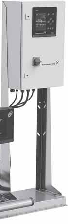
3 CU 352 f f 3. Installing the product Before installing the product, check the following: The booster system corresponds to the order. All visible parts are intact. 3.1 Location Install the booster system in a well-ventilated room to ensure sufficient cooling of the control cabinet and pumps Foundation We recommend that you install the booster system on a plane and rigid concrete foundation which is heavy enough to provide permanent support for the entire system. The foundation must be capable of absorbing any vibration, normal strain or shock.. The weight of a concrete foundation must be 1.5 times the weight of the booster system. English (GB) Hydro MPC is only designed for indoor installation. Do not expose the product to direct sunlight. Place the booster system with a 1 m clearance in front and on the two sides for inspection and removal. 3.2 Mechanical installation Pipes Arrows on the pump base show the direction of flow of water through the pump. The pipes connected to the booster system must be of adequate size. Connect the pipes to the manifolds of the booster system. Either end can be used. Apply sealing compound to the unused end of the manifold, and fit the screw cap. For manifolds with flanges, fit a blanking flange with gasket. To achieve optimum operation and minimise noise and vibration, it may be necessary to consider vibration dampening of the booster system. Noise and vibration are generated by the rotations in the motor and pump and by the flow in pipes and fittings. The effect on the environment is subjective and depends on correct installation and the state of the other parts of the system. If booster systems are installed in blocks of flats or the first consumer on the line is close to the booster system, we recommend that you fit expansion joints on the inlet and outlet pipes to prevent that vibrations are transmitted through the pipes. X L f L f X X X h B TM Fig. 2 Foundation The minimum height of the foundation, h f, is calculated as follows: Fig. 1 Example showing the position of expansion joints, pipe supports and machine shoes Pos. 1 Expansion joint 2 Pipe support 3 Machine shoe TM m pump 1.5 h f = L f B f δ concrete The density δ of concrete is usually taken as 2200 kg/m Vibration dampers To prevent the transmission of vibrations to buildings, we recommend that you isolate the booster system foundation from building parts by means of vibration dampers. The right damper varies from installation to installation, and a wrong damper may increase the vibration level. Vibration dampers must therefore be sized by the supplier. If the booster system is installed on a base frame with vibration dampers, always fit expansion joints on the manifolds. This is important to prevent the booster system from "hanging" in the pipes. Expansion joints, pipe supports and machine shoes shown in fig. 1 are not included in a standard booster system. Tighten all nuts before startup. Fasten the pipes to parts of the building to ensure that they cannot move or be twisted. 3


4 English (GB) Expansion joints Fit expansion joints for these reasons: to absorb expansions or contractions in the pipes caused by changing liquid temperature to reduce mechanical strains in connection with pressure surges in the pipes to isolate mechanical structure-borne noise in the pipes (only rubber bellows expansion joints). Fit expansion joints at a distance of minimum 1 to 1 1/2 times the nominal flange diameter from the manifold on the inlet as well as on the outlet side. This prevents the development of turbulence in the expansion joints, resulting in better inlet conditions and a minimum pressure loss on the pressure side. Fig. 3 Do not install expansion joints to compensate for inaccuracies in the pipes such as centre displacement of flanges. Examples of rubber bellows expansion joints without and with limiting rods Expansion joints with limiting rods can be used to minimise the forces caused by the expansion joints. We always recommend that you use expansion joints with limiting rods for flanges larger than DN 100. Anchor the pipes so that they do not stress the expansion joints and the pump. Follow the supplier s instructions and pass them on to advisers or pipe installers Prefilling of diaphragm tank, if applicable If a diaphragm tank is connected to the system, prefill the tank with nitrogen to this pressure: TM TM Electrical installation The electrical installation must be carried out by an authorised person in accordance with local regulations and the relevant wiring diagram. The electrical installation of the booster system must comply with enclosure class IP54. Check that the power supply and frequency correspond to the values stated on the nameplate. Make sure that the conductor cross-section meets the specifications in the wiring diagram. If the system cannot be installed with the supply disconnecting device located minimum 0.6 m above service level (ground level), install the system with an external "supply disconnecting device" made according to EN , paragraph The system must be provided with a means permitting it to be locked in the OFF (isolated) position. Based on a risk assessment performed by the installer or end-user, the device must be installed in a position according to EN , paragraph The system must be connected to an external emergency stop device or an emergency switchoff device according to the requirements of EN ISO Starting up the product After having carried out the mechanical and electrical installation described in sections 3.2 Mechanical installation and 3.3 Electrical installation, proceed as follows: 1. Switch on the power supply. 2. Wait for the first display to appear. 3. The first time CU 352 is switched on, a startup wizard guides the user through the basic settings. 4. Follow the instructions in each display. 5. When the wizard is completed, check that all pumps are set to "Auto" in the menu "Status". 6. Go to the menu "Operation". 7. Select the operating mode "Normal" and press [OK]. 8. The system is now ready for operation. Hydro MPC-E and -F: Hydro MPC-S: 0.7 x the setpoint. 0.9 x the setpoint. Use nitrogen to avoid corrosion. 4
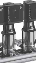
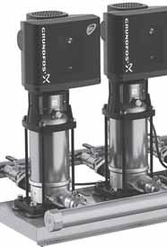
5 4.1 Handling the product The Hydro MPC booster systems with CR 120 or 150 pumps have eyebolts in the base frame. See fig. 4. During handling, the lifting point must always be above the centre of gravity of the booster system. Each lifting strap must be at least 3 m long. English (GB) TM Fig. 5 Hydro MPC booster system TM Fig. 4 Correct lifting of Hydro MPC XL Pos. Quantity CAUTION Overhead load Minor or moderate personal injury - When lifting the booster system, do not use the eyebolts of the motors. - Do not lift the booster system by the manifolds. - Do not stand on the manifolds. CAUTION Crushing of feet Minor or moderate personal injury - When lifting the booster system, do not use the eyebolts of the motors. - Do not lift the booster system by the manifolds. - Do not stand on the manifolds. When lifting the booster system, only use suitable lifting equipment that is in good condition and approved for the weight. The weight is stated on the nameplate of the booster system. Do not use chains for lifting booster systems with CR 120 or CR 150 pumps, as this may damage the motors. 5. Product introduction 5.1 Product description As standard, the booster systems consist of two to six CRI(E) or CR(E) pumps connected in parallel and mounted on a common base frame with a control cabinet and all necessary fittings. A diaphragm tank must be included in some installations. 1 Control cabinet 1 2 Nameplate 1 3 Inlet manifold, stainless steel 1 4 Isolating valve 2 per pump 5 Base frame, stainless steel 1 6 Non-return valve 1 per pump 7 Outlet manifold, stainless steel 1 8 Pressure transmitter and pressure gauge 1 9 Pump Diaphragm tank Control variant The Hydro MPC booster systems are divided into three groups based on the control variant: Control variant -E Two to six electronically speed-controlled pumps. From 0.37 to 22 kw, Hydro MPC-E is equipped with CR(I)E pumps with integrated frequency converter. As from 30 kw, Hydro MPC-E is equipped with CR pumps connected to Grundfos CUE frequency converters (one per pump). Two to six CR(I) pumps connected to a Grundfos -F CUE frequency converter. The speed-controlled operation alternates between the pumps. -S Two to six mains-operated CR(I) pumps Design code E-I only uses CR pumps connected to Grundfos CUE frequency converters (one per pump). See also section 6. Overview of control variants. Hydro MPC always include application-optimised software for setting the booster system to the application in question. 5
6 English (GB) 5.3 Identification Nameplate The nameplate of the booster system is fitted on the base frame. See position 2 in fig. 6. Type: 1 Model: 2 Serial No.: Main supply: 3 4 pmax: bar 5 Q Nom / Max: / Liq. temp.: C 6 H Nom / Max: / m 3 /h m Software label The software label is placed on the back of the CU 352 control unit. Fig Control MPC 3. Hydro MPC C-MPC options 4. H-MPC options 2 CONFIGURATION STEPS - PLEASE FOLLOW THE NUMBERS Software label 5. Pump data TM Fig. 6 9 IP Class: Weight: kg 11 MADE IN GERMANY 14 Nameplate 10 QR code DK Bjerringbro - Denmark 15 TM Pos. 1 Control MPC - GSC file number 2 Control MPC options - GSC file numbers 3 Hydro MPC - GSC file number* 4 Hydro MPC options - GSC file numbers* 5 Pump data - GSC file numbers** * Applies only to booster systems. ** Applies only to CR, CRI, CRN, CRE and CRIE pumps. Pos. 1 Product type 2 Code for model 3 Serial number 4 Mains supply 5 Maximum operating pressure 6 Liquid temperature 7 Nominal flow rate [m 3 /h] 8 Maximum flow rate [m 3 /h] 9 Technical documents 10 Enclosure class 11 Weight 12 Approval marks 13 QR code 14 Country of origin 15 Company address A GSC (Grundfos Standard Configuration) file is a configuration data file. 6
7 5.4 Type key Code Example Hydro MPC -E 6 CRE U1 A- A- A- ABCD E F S X U1 U2 U3 U4 U5 U6 U7 U8 U9 UA UB UC UD UX A C D E F G H I W A B C A B C D H I X A B C D E F G H I J K L M N O Q P S T U V W X Type range System type All pumps, E-motor or CUE Fixed-speed pumps, one CUE Fixed-speed pumps Customised-system pumps Number of main pumps Pump type Voltage code 3 x V, N, PE, 50/60 Hz 3 x V, PE, 50/60 Hz 3 x V, N, PE, 50 Hz 3 x V, PE, 50 Hz 3 x V, N, PE, 60 Hz 3 x V, PE, 60 Hz 1 x V, PE, 50/60 Hz 1 x V, N, PE, 50/60 Hz 3 x V, PE, 60 Hz 3 x V, PE, 60 Hz 1 x V, N, PE, 50/60 Hz 1 x V, N, PE, 50 Hz 3 x V, N, PE, 60 Hz CSU variant (special voltage rating) Design Systems with the control cabinet mounted on the same base frame as the pumps Systems with the control cabinet mounted on its own base for floor mounting* Systems with the control cabinet mounted on its own base frame* ASEAN design and systems with the control cabinet mounted on the same base frame as the pumps ASEAN design and systems with the control cabinet centred on the base frame ASEAN design and systems with the control cabinet mounted on its own base for floor mounting* ASEAN design and systems with the control cabinet mounted on its own base frame* ASEAN design and systems with the control cabinet prepared for wall mounting* Systems with the control cabinet prepared for wall mounting* Starting method E DOL SD Material combination Stainless-steel manifold, base frame and standard valves Stainless-steel manifold, base frames and standard valves Galvanised-steel manifold, base frame and standard valves Stainless-steel manifold, galvanised steel base frame and standard valves Galvanised-steel manifold, base frame painted black and standard valves Stainless-steel manifold, base frame painted black and standard valves Customised material combination Options Standard hydraulics Pilot pump Bypass Non-return valve Elbow manifold No inlet manifold Diaphragm tank Dry-running protection Repair switch Redundant sensor One free position Two free positions Three free positions PN 10 pressure rating PN 25 pressure rating PN 40 pressure rating Low precharge pressure Customised variant Certificate Undersized motor Standard controls with options Customised controls More than four options English (GB) Design code: E-I is only available in selected countries. * The control cabinet can be placed up to 2 m from the pumps. 7
8 English (GB) 6. Overview of control variants The table shows examples of systems. Systems with speed-controlled pumps Systems with pumps connected to one CUE frequency converter Systems with mains-operated pumps Hydro MPC-E Hydro MPC-F Hydro MPC-S Hydro MPC booster system with three CR(I)E pumps. System with three CR pumps connected to one Grundfos CUE frequency converter in the control cabinet. The speed-controlled operation alternates between the pumps. System with three mains-operated CR(I) pumps. TM PT PT PT TM TM One CR(I)E pump in operation. One CR pump connected to one Grundfos CUE frequency converter in operation. One mains-operated CR(I) pump in operation. H H H H set Q TM H set Q TM H stop H set Q TM Three CR(I)E pumps in operation. One CR pump connected to one Grundfos CUE frequency converter and two mains-operated CR pumps in operation. Three mains-operated CR(I) pumps in operation. H H H H set Q TM H set Q TM H stop H set Q TM Hydro MPC-E maintains a constant pressure through continuous adjustment of the speed of the pumps. The system performance is adjusted to the demand through cutting in/out the required number of pumps and through parallel control of the pumps in operation. Pump changeover is automatic and depends on load, operating hours and fault. All pumps in operation will run at equal speed. Hydro MPC-F maintains a constant pressure through continuous adjustment of the speed of the CR pump connected to the Grundfos CUE frequency converter. The speedcontrolled operation alternates between the pumps. One CR pump connected to the Grundfos CUE frequency converter always starts first. If the pressure cannot be maintained by the pump, one or two mains-operated CR pumps will be cut in. Pump changeover is automatic and depends on load, operating hours and fault. Hydro MPC-S maintains an almost constant pressure through cutting in/ out the required number of pumps. The operating range of the pumps will lie between H set and H stop (cut-out pressure). Pump changeover is automatic and depends on load, operating hours and fault. 8
9 7. Operating panel 7.1 Display The operating panel in the front cover of the control cabinet features a display, a number of buttons and two indicator lights. The operating panel enables manual setting and monitoring of the performance of the system. A B English (GB) CU Fig. 8 Operating panel Pos. 1 Display 2 Arrow to the right 3 Help 4 Up 5 Down 6 Plus 7 Minus 8 Back 9 Home 10 OK 11 Indicator light, operation (green) 12 Indicator light, fault (red) 13 Brightness TM Fig. 9 Display design Menu line The menu line (A) is illustrated in fig. 9. The display has four main menus: Status Operation Alarm D Settings Indication of system status Change of operating parameters such as setpoint Alarm log for fault finding Change of settings (password option) Top line The top line (B) is illustrated in fig. 9. It shows the following: the display number and title (left side) the selected menu (left side) the symbol in case of alarm (right side) the symbol in case of warning (right side) the symbol if the service language has been selected (right side). C TM Graphical illustration The graphical illustration (D) may show a status, an indication or other elements, depending on the position in the menu structure. The illustration may show the entire system or part of it as well as various settings Scroll bar If the list of illustration elements exceeds the display, the symbols and appear in the scroll bar to the right. Move up and down in lists with these symbols Bottom line The bottom line (C) shows the date and time. 9
10 English (GB) 7.2 Buttons and indicator lights The buttons (2 to 10 in fig. 8) on CU 352 are active when they are on Arrow to the right (2) Press [>] to go to the next menu in the menu structure. If you press [>] when the menu "Settings" is highlighted, you will go to the menu "Status" Help (3) When this symbol is on, a help text applying to the display will appear if you press the button. Close the text with Up and down (4 and 5) Move up and down in lists with [ ] and [ ]. You can select a text with [OK] when it is in a box. If a text is marked and you press [ ], the text above will be marked. If you press [ ], the text below will be marked. If you press [ ] in the last line in the list, the first line will be marked. If you press [ ] in the first line in the list, the last line will be marked Plus and minus (6 and 7) Increase and reduce a value with [+] and [-]. Save with [OK] Back (8) Press to go one display back in the menu. If you have changed a value and press, the new value will not be saved. See also section OK (10). If you press [OK] before pressing, the new value will be saved. See also section OK (10) Home (9) Press to return to the menu "Status" OK (10) Use the button as an enter button. The button is also used to start the setting of a value. If you have changed a value, press [OK] to save the change Indicator lights (11 and 12) The operating panel incorporates a green and red indicator light. The green indicator light will be on when the system is in operation and flash when the system has been set to stop. The red indicator light will be on if there is an alarm or a warning. The fault can be identified from the alarm list Brightness (13) You can change the brightness in the display with this button: 1. Press. 2. Adjust the brightness with [+] and [-] Back light If no button is touched for 15 minutes, the back light of the display will be dimmed, and the first display in the menu "Status" will appear. Press any button to re-activate the back light. 10
11 8. Functions 8.1 Tree of functions The functions depend on the configuration of the system. 1. Status 2. Operation 3. Alarm Continued on page Status 2. Operation 3. Alarm status 3.1 Actual alarms 2.1 Further settings 3.1 Actual alarms System operating mode 3.2 Alarm log 1.2 System Control mode 3.3 Service contact information Operating mode Alternative setpoints Setpoint Individual pump control Setpoint influence Pump Measured values Pilot pump Analog inputs Log graph Battery status 1.3 Pump Pump Pump Pump Pump Pump Pilot pump 1.11 Electrical overview English (GB) Key to the four menus Status This menu shows alarms, status of the system and a graph of logged data. Note: No settings can be made in this menu. Operation In this menu, you can set the basic parameters, such as setpoint, operating mode, control mode and individual pump control. Alarm This menu gives an overview of alarms and warnings. You can reset alarms and warnings in this menu. Settings In this menu, you can set various functions: Primary controller PI controller, Alternative setpoints, External setpoint influence, Primary sensor, Secondary sensor, Clock program, Proportional pressure, S-system configuration, Setpoint ramp. Pump cascade control Min. time between start/stop, Max. number of starts/hour, Number of standby pumps, Forced pump changeover, Pump test run, Pump stop attempt, Pump start and stop speed, Min. performance, Compensation for pump start-up time. Secondary functions Stop function, Soft pressure build-up, Digital inputs, Analog inputs, Digital outputs*, Analog outputs, Counter inputs, Emergency run, Min., max. and user-defined duty, Pump curve data, Control source, Fixed inlet pressure, Flow estimation, Reduced operation, Multisensor settings. Monitoring functions Dry-running protection, Min. pressure, Max. pressure, External fault, Limit 1 exceeded, Limit 2 exceeded, Pumps outside duty range, Pressure relief, Log values, Fault, primary sensor, Non-return valve. Functions, CU 352 Display language, Units, Date and time, Password, Ethernet, GENIbus number Software status, Display 1, Display 2, Display 3. * If an IO 351 is installed. 11
12 English (GB) Continued from page > 4. Settings 4.1 Primary controller PI controller Alternative setpoints Alternative setpoints External setpoint influence Input value to be influenced by Setting of influence function Primary sensor Secondary sensor Clock program Proportional pressure S-system configuration Setpoint ramp 4.2 Pump cascade control Min. time between start/stop Max. number of starts/hour Standby pumps Forced pump changeover Pump test run Pump stop attempt Pump start and stop speed Min. performance Compensation for pump start-up time 4.3 Secondary functions Stop function Stop parameters Soft pressure build-up Emergency run Digital inputs Function, DI1 (CU 352) - DI3, [10, 12, 14] Function, DI1 (IO ) - DI9, [10-46] Function, DI1 (IO ) - DI9, [10-46] Analog inputs Setting, AI1 (CU 352), [51] - AI3, [51, 54, 57] Function, AI1 (CU 352) - AI3 [51, 54, 57] Setting, AI1 (IO ), [57] - AI2 [57, 60] Function, AI1 (IO ) - AI2 [57, 60] Setting, AI1 (IO ), [57] - AI2 [57, 60] Function, AI1 (IO ) - A2 [57, 60] Digital outputs DO1 (CU 352), [71] is signalling - DO2 [71, 74] DO1 (IO ), [77] is signalling - DO7 [77-88] DO1 (IO ), [77] is signalling - DO7 [77-88] Analog outputs AO1 (IO ) [18] - AO3 [18, 22, 26] AO1 (IO ) [18] - AO3 [18, 22, 26] Counter inputs Min., max. and user-defined duty Min. duty Max. duty Set user-defined duty Pump curve data Flow estimation Control source Fixed inlet pressure Flow estimation Reduced operation Multisensor settings 4.4 Monitoring functions Dry-running protection Pressure/level switch Measurement, inlet pressure Measurement, tank level Min. pressure Max. pressure External fault Limit 1 exceeded Limit 2 exceeded Pumps outside duty range Pressure relief Log values Fault, primary sensor Non-return valve 4.5 Functions, CU 352 Change language to the service Run wizard again Display language Units Pressure Differential pressure Head Level Temperature Date and time Flow rate Power Password Volume Energy Ethernet Specific GENIbus number Software status 12
13 8.2 Overview Section Display and display number Page 8.4 Status (1) Actual alarms (3.1) System (1.2) Operating mode (1.2.1) Setpoint (1.2.2) Setpoint influence (1.2.3) Measured values (1.2.4) Analog inputs (1.2.5) Log graph (1.2.6) Battery status (1.2.7) Pump 1-6, Pilot pump ( ) Operation (2) Operation (2) System operating mode (2.1.1) Control mode (2.1.2) Alternative setpoints (2.1.3) Individual pump control (2.1.4) Pump 1-6 ( ) Operation, pilot pump( ) Alarm (3) Alarm status (3) Actual alarms (3.1) Alarm log (3.2) Service contact information (3.3) Settings (4) Primary controller (4.1) PI controller (4.1.1) Alternative setpoints (4.1.2) Alternative setpoints 2-7 ( ) External setpoint influence (4.1.3) Setting of influence function ( ) Primary sensor (4.1.4) Clock program (4.1.6) Proportional pressure (4.1.7) S-system configuration (4.1.8) Setpoint ramp (4.1.9) Pump cascade control (4.2) Min. time between start/stop (4.2.1) Max. number of starts/hour (4.2.1) Standby pumps (4.2.3) Forced pump changeover (4.2.4) Pump test run (4.2.5) Pump stop attempt (4.2.7) Pump start and stop speed (4.2.8) Min. performance (4.2.9) Compensation for pump start-up time (4.2.10) Secondary functions (4.3) Stop function (4.3.1) Soft pressure build-up (4.3.3) Emergency run (4.3.5) Digital inputs (4.3.7) Functions of digital inputs ( ) Analog inputs (4.3.8) Analog inputs ( to ) Analog inputs and measured value ( ) Digital outputs (4.3.9) 46 English (GB) 13
14 English (GB) Section Display and display number Page Function of digital outputs ( ) Analog outputs (4.3.10) Output signal ( ) Min., max. and user-defined duty (4.3.14) Min. duty ( ) Max. duty ( ) User-defined duty ( ) Pump curve data (4.3.19) Control source (4.3.20) Fixed inlet pressure (4.3.22) Flow estimation (4.3.23) Reduced operation (4.3.24) Monitoring functions (4.4) Dry-running protection (4.4.1) Pressure/level switch ( ) Measurement, inlet pressure ( ) Measurement, tank level ( ) Min. pressure (4.4.2) Max. pressure (4.4.3) External fault (4.4.4) Limit 1 exceeded ( ) Pumps outside duty range (4.4.7) Pressure relief (4.4.8) Log values (4.4.9) Fault, primary sensor (4.4.10) Functions, CU 352 (4.5) Display language (4.5.1) Units (4.5.2) Date and time (4.5.3) Password (4.5.4) Ethernet (4.5.5) GENIbus number (4.5.6) Software status (4.5.9) Status display menu (4.6) 64 14
 The first status display is shown below.")
15 8.3 of functions The description of functions is based on the four main menus of the CU 352 control unit: Status Operation Alarm Settings. The functions apply to all control variants unless otherwise stated. 8.4 Status (1) The first status display is shown below. This display is shown when the power is switched on, and it appears if the buttons of the operating panel remain untouched for 15 minutes. E I C D Fig. 10 Status No settings can be made in this menu. The actual value (process value, PV) of the control parameter, usually the outlet pressure, is shown in the upper right corner (G) together with the selected setpoint (SP) (H). The upper half of the display (A) shows a graphic illustration of the pump system. The selected measuring parameters are shown with sensor symbol and actual value. In MPC-E systems where the differential pressure across the pumps and pump curve data are known, the display shows the estimated flow rate when the flow rate and speed of the pumps are within a range where it is possible to estimate the flow rate. A B F G H The lower display half (B) shows the following: the most recent active alarm, if any, and the fault cause with the fault code in brackets system status with actual operating mode and control source pump status with actual operating mode. If a fault has occurred, the warning symbol or alarm symbol is shown in the line (C) together with the cause and fault code, for instance "Overtemperature (64)". If the fault is related to one of the pumps, one of the symbols or is also shown in front of the status line (D) of the pump in question. At the same time, the pump status indicator (E) changes colour to either yellow or red as described in the table below. The symbol or is shown to the right in the top line of the display (F). As long as a fault is present, this symbol is shown in the top line of all displays. To open a menu line, select the line with [ ] or [ ] and press [OK]. The display allows you to open status displays showing the following: actual alarms system status status of each pump. of pump status Pump status indicator Rotating, green Permanently green Rotating, yellow Permanently yellow Permanently red The pump is running. The pump is ready (not running). Warning. The pump is running. Warning. The pump is ready (not running). Alarm. The pump is stopped. English (GB) : This indicates that the flow rate is an estimated value. The estimated flow rate may differ from a measured value. In the middle of the display, an information field (I) is shown if any of the following events occurs: Limited operation due to standby pump Proportional-pressure influence active External setpoint influence active Alternative setpoint active Low flow boost active Pressure relief active Clock program active Remote-controlled via GENI (RS-485) Limited due to reduced operation Stopped due to low flow. 15
 and 8.6.3 Alarm log (3.2). 8.4.2 System (1.2) Fig. 12 System This display shows the operational state of the system. Go to subdisplays for further details.")

16 English (GB) Actual alarms (3.1) Operating mode (1.2.1) Fig. 11 Actual alarms This display shows active unreset alarms and warnings. For further information, see sections Actual alarms (3.1) and Alarm log (3.2) System (1.2) Fig. 12 System This display shows the operational state of the system. Go to subdisplays for further details. The display allows you to open displays about the following: Operating mode Setpoint Setpoint influence Measured values Analog inputs Log graph Battery status. Fig. 13 Operating mode This display shows the operating mode of the system and from where it is controlled. Operating modes The system has six operating modes: 1. Normal The pumps adapt their performance to the requirement. 2. Max. The pumps run at a constant high speed. Normally, all pumps run at maximum speed. 3. User-defined The pumps run at a constant speed set by the user. It is usually is a performance between "Max." and "Min.". 4. Min. The pumps run at a constant low speed. Normally, one pump is running at a speed of 70 %. 5. Stop All pumps have been stopped. 6. Emergency run The pumps run according to the setting made in display Emergency run (4.3.5). The performance required in these operating modes can be set in the menu "Settings": Max. Min. User-defined Emergency run. See sections Min., max. and user-defined duty (4.3.14) and Emergency run (4.3.5). The actual operating mode can be controlled from four different sources: Fault External signal CU 352 Bus. Control source You can set the system to remote control via an external bus (option). In this case, you must set a setpoint and an operating mode via the bus. In the menu "Settings", you can select whether CU 352 or the external bus is to be the control source. The status of this setting is shown in the display "Operating mode". 16
. At the same time, the selected setpoint is shown.")


17 8.4.4 Setpoint (1.2.2) Measured values (1.2.4) English (GB) Fig. 14 Setpoint This display shows the selected setpoint and whether it comes from CU 352 or an external bus. The display also shows all seven possible setpoints from CU 352 (for closed- and open-loop control). At the same time, the selected setpoint is shown. As it is a status display, no settings can be made. You can change the setpoints in the menus "Operation" or "Settings". See section Alternative setpoints (4.1.2) Setpoint influence (1.2.3) Fig. 16 Measured values This display gives a general status of all measured and calculated parameters. In MPC-E systems with a flowmeter, the specific energy is shown as an average value and actual value (mean value over the last minute). The average value is based on the accumulated flow shown as total volume. The total volume and specific energy average can be reset in this display. The lines "Power consumption" and "Energy consumption" are only shown in MPC-E systems Analog inputs (1.2.5) Fig. 15 Setpoint influence The selected setpoint can be influenced by parameters. The parameters are shown as percentage from 0 to 100 % or as a pressure measured in bar. They can only reduce the setpoint, as the influence in percentage divided with 100 is multiplied with the selected setpoint: Actual setpoint (SP) = selected setpoint x influence (1) x influence (2) x etc. The display shows the parameters influencing the selected setpoint and the percentage or value of influence. You can set some of the possible parameters in the display External setpoint influence (4.1.3). The parameter "Low flow boost" is set as a start/stop band as a percentage of the setpoint set in the display Stop function (4.3.1). The parameter is set as a percentage in the display Proportional pressure (4.1.7). Finally, the resulting actual setpoint (SP) is shown. Fig. 17 Analog inputs This display shows an overview of the analog inputs and the measured values of each input. See sections Analog inputs (4.3.8), Analog inputs ( to ) and Analog inputs and measured value ( ). 17
. Various values can be shown, and the time scale can be changed. Status > System > Log graph 1. Set as a percentage: Zoom begins at Zoom ends at 2.")

18 English (GB) Log graph (1.2.6) Pump 1-6, Pilot pump ( ) Fig. 18 Log graph In this display, you can see logged data stored in the controller. Select log values in the display Log values (4.4.9). Various values can be shown, and the time scale can be changed. Status > System > Log graph 1. Set as a percentage: Zoom begins at Zoom ends at 2. Select values to be shown Battery status (1.2.7) Fig. 19 Battery status Here you can see the status of the backup battery, if installed. Fig. 20 Pump 1 This display shows the operational state of the individual pumps. The displays for the pilot pump are only shown if such pumps are installed. The pumps can have different operating modes: Auto Together with the other pumps in automatic operation, the pump is controlled by the PI controller which ensures that the system delivers the required performance. Manual The pump is not controlled by the PI controller. In manual operation, the pump has one of the following operating modes: Max. The pump runs at a set maximum speed. (This operating mode can only be selected for variable-speed pumps.) Normal The pump runs at a set speed. Min. The pump runs at a set minimum speed. (This operating mode can only be selected for variable-speed pumps.) Stop The pump has been forced to stop. Besides information about the operating mode, you can read various parameters in the status display, such as these: Actual operating mode Control source Speed (only 0 or 100 % are shown for mains-operated pumps) Power (only MPC-E/-EC) Energy consumption (only MPC-E/-EC) Operating hours Temperature. 18

, that is the setpoint acting as reference for the PI controller.")
19 8.5 Operation (2) In this menu, you can set the basic parameters, such as setpoint, operating mode, control mode and individual pump control Operation (2) System operating mode (2.1.1) English (GB) A B C Fig. 22 System operating mode Fig. 21 Operation The column shows the setting range. In closed-loop control, it corresponds to the range of the primary sensor, here 0-16 bar. In open-loop control, the setting range is %. At the left hand of the column, you can see the selected setpoint 1 (A), that is the value set in the display. At the right hand of the column, you can see the actual setpoint (B), that is the setpoint acting as reference for the PI controller. If no kind of external setpoint influence has been selected, the two values will be identical. The measured value (outlet pressure) is shown as the grey part of the column (C). See sections External setpoint influence (4.1.3) and Setting of influence function ( ). Below the display is a menu line for setting of setpoint 1 and selection of operating mode, including the operating modes "Normal" and "Stop". You can select further settings: "System operating mode", "Control mode", "Alternative setpoints" and "Individual pump control". Setpoint: Closed-loop control: Measuring range of the primary sensor Open-loop control: % Setpoint Operation > Set setpoint 1, open loop / Set setpoint 1, closed loop. Set the value. Operating mode Operation Select: Normal or Stop. Further settings Operation > Further settings. Select one of the settings below: System operating mode (see section 8.5.2). Control mode (see section 8.5.3). Alternative setpoints (see section 8.5.4). Individual pump control (see section 8.5.6). The setpoint is a value suitable for the system in question. The factory setting may have been changed in the startup menu. The system can be set to six different operating modes. "Normal" is the typical setting. See section Operating mode (1.2.1). You can set the performance of the operating modes in this menu: Min. Max. User-defined Emergency. Normal Max. Min. User-defined Stop Emergency. Operation > Further settings > System operating mode > Operating mode. Select the desired line at the bottom of the display to set the performance for "Max.", "Min.", "User-defined" and "Emergency" run. See sections Min., max. and user-defined duty (4.3.14) and Emergency run (4.3.5). Normal. 19
20 English (GB) Control mode (2.1.2) Operation > Further settings > Control mode > Closed loop. Set the setpoint. See sections Alternative setpoints (2.1.3) and Operation (2). Open loop In open-loop control mode, the pumps run at a fixed speed. The pump speed is calculated from the performance set by the user (0-100 %). The pump performance in percentage is proportional with the flow rate. Open-loop control mode is usually used when the system is controlled by an external controller which controls the performance via an external signal. The external controller could for instance be a building management system connected to the MPC system. In such cases MPC is like an actuator. See figs 26 and 27. Fig. 23 Control mode There are two control modes, namely closed and open loop. Closed loop The typical control mode is "Closed loop" where the built-in PI controller ensures that the system reaches and maintains the selected setpoint. The performance is based on the setpoint set for closed loop. See figs 24 and 25. Fig. 26 Booster system with external controller (open loop) TM Flow rate [m 3 /h] Fig. 24 Booster system controlled by built-in PI controller (closed loop) TM Input [%] from external controller TM P [bar] Fig. 27 Regulation curve for open loop Flow rate [m 3 /h] 100 Setpoint Fig. 25 Regulation curve for closed loop Time [s] TM Flow rate Pump 1 Pump 2 Pump 3 Pump Input [%] from external controller TM Fig. 28 Regulation curve for MPC-E system in open loop 20
21 Flow rate [m 3 /h] Flow rate Pump 1 Pump 2 Pump 3 Pump 4 Input [%] from external controller Fig. 29 Regulation curve for MPC-F system in open loop Flow rate [m 3 /h] Flow rate Pump 1 Pump 2 Pump 3 Pump 4 Input [%] from external controller Fig. 30 Regulation curve for MPC-S system in open loop These settings must be made in connection with open loop: Open loop Set setpoint 1, open loop External setpoint influence Normal. TM TM Proceed as follows to set an external control source to control the system: Operation > Further settings > Control mode. Select: Open loop. 1. Press x Select: Stop 3. Set to 100 %: Set setpoint 1, open loop. 4. Settings > Primary controller > External setpoint influence > Go to setting of analog input. 5. Select analog input and range. 6. Select: Measured input value. Display appears. Select: % signal. 7. Press. 8. Set the minimum and maximum sensor value. 9. Press x Select: Input value to be influenced by % signal. 11. Press. 12. Select: Set the influence function. See also section Setting of influence function ( ). 13. Set the number of points. 14. Set for Point 1: External input value Reduce setpoint to 15. Repeat step 14 for all selected points. 16. Press. 17. Set as seconds: Filter time. 18. Select: Enabled. 19. Press x Select: Operation Normal. The booster system can now be controlled by an external controller. Closed loop. English (GB) 21
, you can set six alternative setpoints for closed-loop control mode.")
22 English (GB) Alternative setpoints (2.1.3) Individual pump control (2.1.4) Fig. 31 Alternative setpoints In addition to the primary setpoint 1 (shown in display 2 in menu "Operation"), you can set six alternative setpoints for closed-loop control mode. Furthermore, you can set seven setpoints for openloop control mode. You can activate one of the alternative setpoints by means of external contacts. See sections Alternative setpoints (4.1.2) and Alternative setpoints 2-7 ( ). The setting range of setpoints for closed-loop control mode depends on the range of the primary sensor. See section Primary sensor (4.1.4). In open-loop control mode, the setting range is %. Operation > Further settings > Alternative setpoints. Set the setpoint. Setpoint 1 for closed-loop control mode is a value suitable for the system in question. The alternative setpoints for closed-loop control mode are 3 bar. All setpoints for open-loop control mode are 70 %. Fig. 32 Individual pump control You can change the operating mode from automatic operation to one of the manual operating modes. Auto The pumps are controlled by the PI controller, ensuring that the system delivers the required performance. Manual The pump is not controlled by the PI controller, but set to one of the following manual operating modes: Max. The pump runs at a set maximum speed. (This operating mode can only be selected for variable-speed pumps.) Normal The pump runs at a set speed. Min. The pump runs at a set minimum speed. (This operating mode can only be selected for variable-speed pumps.) Stop The pump has been forced to stop. Pumps in manual operation are not part of the normal pump cascade and speed control. The manual pumps are a "disturbance" of the normal operation of the system. If one or more pumps are in manual operation, the system may not be able to deliver the set performance. There are two displays for the function. In the first display, select the pump to be set, and in the next display, select the operating mode. All pumps can be selected. Operation > Further settings > Individual pump control. 22
23 8.5.6 Pump 1-6 ( ) Operation, pilot pump( ) English (GB) Fig. 33 Pump 1-6 This display is shown for the individual pumps and it allows you to set an operating mode. You can select "Auto" or "Manual" as well as the operating mode of the pump for manual operation - "Max.", "Normal", "Min." or "Stop". For mains-operated pumps, you can only select "Normal" or "Stop". Operation > Further settings > Individual pump control. 1. Select pump. 2. Select resetting: Auto or Manual. 3. Manual: Select operating mode. Normal: Set the setpoint. Auto. Fig. 34 Operation, pilot pump This display is only shown in systems that have been configured with a pilot pump. You can set the operating mode and setpoint for the pilot pump. Auto Select this mode if the pilot pump is to be used as a backup pump. If the pilot pump is selected as a backup pump, it will start if the main pumps are running at 100 % speed and still cannot reach or maintain the setpoint. The setpoint of the pilot pump can either be set to the same value as that of the main pumps by selecting "Use system setpoint" or to another value. Manual Max., Normal, Min., Stop. Operation > Further settings > Individual pump control > Pilot pump. Select resetting: Auto or Manual. Auto 1. Select if the pump is also to be used as backup pump (only possible if the system does not already incorporate a backup pump). 2. Select "Use system setpoint" or enter a setpoint. Manual 1. Select operating mode. 2. Normal: Set the setpoint. Auto. Use system setpoint. 23
24 English (GB) 8.6 Alarm (3) This menu gives an overview of alarms and warnings. You can reset alarms Alarm status (3) Fig. 35 Alarm status A fault in the system or one of the components monitored can cause an alarm or a warning. Besides the fault signal via the alarm and warning signal relay and the red indicator light on CU 352, an alarm can also cause a change of operating mode, for instance from "Normal" to "Stop". A warning only causes a fault indication. The table shows the possible causes of fault together with an alarm code, and whether they result in an alarm or a warning. It also shows to what operating mode the system will change in case of alarm, and whether restarting of the system and resetting of the alarm is manual or automatic. The table also shows that the reaction to some of the fault causes mentioned can be set in the menu "Settings". See sections Soft pressure build-up (4.3.3) and Monitoring functions (4.4) to Pressure relief (4.4.8). 24
25 Fault Warning ( ) Alarm ( ) Change of operating mode to Resetting of alarm, restarting Set in the menu "Settings" Alarm code Water shortage Manual/automatic X 206 Water shortage Stop Manual/automatic X 214 English (GB) Pressure high Stop Manual/automatic X 210 Pressure low Stop Manual/automatic Manual/automatic X 211 Pressure relief Manual/automatic X 219 Alarm, all pumps Stop Automatic 203 External fault Stop Manual/automatic Manual/automatic X 3 Dissimilar sensor signals Automatic 204 Fault, primary sensor Stop Automatic 89 Fault, sensor Automatic 88 Communication fault Automatic 10 Phase failure Automatic 2 Undervoltage, pump Automatic 7, 40, 42, 73 Overvoltage, pump Automatic 32 Overload, pump Automatic 48, 50, 51, 54 Motor temperature too high Automatic 64, 65, 67, 70 Other fault, pump Automatic 76, 83 Internal fault, CU 352 Automatic 83, 157 Internal fault, IO 351 Stop Automatic 72, 83, 157 VFD not ready Automatic 213 Fault, ethernet Automatic 231, 232 Limit 1 exceeded Manual/automatic X 190 Limit 2 exceeded Manual/automatic X 191 Pressure buildup fault Manual/automatic X 215 Pumps outside duty range Manual/automatic X 208 Fault, pilot pump Automatic 216 Multisensor fault Automatic 143 Multisensor value exceeds limits Automatic X 87 Signal fault, secondary sensor Automatic X 93 Non-return valve fault Manual/automatic X 209 Non-return valve fault Manual/automatic X
26 English (GB) Actual alarms (3.1) Alarm log (3.2) The alarm log can store up to 24 warnings and alarms. Fig. 36 Actual alarms This submenu shows the following: Warnings caused by faults that still exist. Warnings caused by faults that have disappeared, but the warning requires manual resetting. Alarms caused by faults that still exist. Alarms caused by faults that have disappeared, but the alarm requires manual resetting. All warnings and alarms with automatic resetting are automatically removed from the menu when the fault has disappeared. Alarms requiring manual resetting can be reset in this display by pressing [OK]. An alarm cannot be reset until the fault has disappeared. For every warning or alarm, the following is shown: Whether it is a warning or an alarm. Where the fault occurred: System, Pump 1, Pump 2, etc. In case of input-related faults, the input is shown. The cause of the fault and the alarm code in brackets, such as "Water shortage (214)". When the fault occurred: Date and time. When the fault disappeared: Date and time. If the fault still exists, date and time are shown as " ". The most recent warning or alarm is shown at the top of the display. Fig. 37 Alarm log This display shows warnings and alarms. For every warning or alarm, the following is shown: Whether it is a warning or an alarm. Where the fault occurred: System, Pump 1, Pump 2, etc. In case of input-related faults, the input is shown. The cause of the fault and the alarm code in brackets, such as "Water shortage (214)". When the fault occurred: Date and time. When the fault disappeared: Date and time. If the fault still exists, date and time are shown as " ". The most recent warning or alarm is shown at the top of the display Service contact information (3.3) Fig. 38 Service contact information This display shows the contact information of the installer if entered during commissioning. 26
27 8.7 Settings (4) Primary controller (4.1) English (GB) Fig. 39 Settings In this menu, you can set the following functions: Primary controller PI controller, Alternative setpoints, External setpoint influence, Primary sensor, Secondary sensor, Clock program, Proportional pressure, S-system configuration, Setpoint ramp. Pump cascade control Min. time between start/stop, Max. number of starts/hour, Number of standby pumps, Forced pump changeover, Pump test run, Pump stop attempt, Pump start and stop speed, Min. performance, Compensation for pump start-up time. Secondary functions Stop function, Soft pressure build-up, Digital inputs, Analog inputs, Digital outputs*, Analog outputs, Counter inputs, Emergency run, Min., max. and user-defined duty, Pump curve data, Control source, Fixed inlet pressure, Flow estimation, Reduced operation, Multisensor settings. Monitoring functions Dry-running protection, Min. pressure, Max. pressure, External fault, Limit 1 exceeded, Limit 2 exceeded, Pumps outside duty range, Pressure relief, Log values, Fault, primary sensor, Nonreturn valve. Functions, CU 352 Display language, Units, Date and time, Password, Ethernet, GENIbus number Software status, Display 1, Display 2, Display 3. The service language, British English, can be selected for service purposes. All these functions are usually set correctly when the system is switched on. Fig. 40 Primary controller In this menu, you can set the functions related to the primary controller. It is only necessary to make settings in this menu if the functionality is to be expanded with one of the functions below: PI controller Alternative setpoints External setpoint influence Primary sensor Secondary sensor Clock program Proportional pressure S-system configuration. 27
28 English (GB) PI controller (4.1.1) PI controller settings for heating and cooling If another application than pressure boosting has been selected in the startup wizard, the values of Kp and Ti are set automatically according to the table below. As the system does not know the pipe length, the default parameters are set according to the table to a pipe length (L1 or L2) of 5 metres. System/application Heating system 1) Kp Cooling system 2) Ti [seconds] Fig. 41 PI controller The system includes a standard PI controller which ensures that the pressure is stable and corresponds to the setpoint. You can adjust the PI controller if a faster or slower reaction to changes of consumption is required. To obtain a faster reaction, increase Kp and reduce Ti. To obtain a slower reaction, reduce Kp and increase Ti. "Gain Kp": -30 to 30. Note: For inverse control, set Kp to a negative value. "Integral time Ti": 0.1 to 3600 seconds. Settings Primary controller PI controller. 1. Set "Gain Kp" and "Integral time Ti". Note: Usually it is not necessary to adjust Kp. The setting of Kp and Ti depends on the system and application. PI controller settings for pressure boosting If the application has been set to pressure boosting in the startup wizard, the following values of Kp and Ti are set automatically: Kp: 0.5 Ti: 1 second. L [m] 1 t Q L 2 [m] L 2 [m] L 2 [m] t 1) Heating systems are systems in which an increase in pump performance will result in a temperature rise at the sensor. 2) Cooling systems are systems in which an increase in pump performance will result in a temperature drop at the sensor. L1: Distance [m] between pump and sensor. L2: Distance [m] between heat exchanger and sensor. ΔP: Measurement of differential pressure. Q: Measurement of flow rate. t: Measurement of temperature. Δt: Measurement of differential temperature. 0.5 L1 < 5 m: 1 L1 > 5 m: 3 L1 > 10 m: L L L2 28
 as alternatives to the primary setpoint (1). The primary setpoint (1) is set in the menu \"Operation\".")
29 8.7.3 Alternative setpoints (4.1.2) Alternative setpoints 2-7 ( ) English (GB) Fig. 42 Alternative setpoints This function allows you to select up to six setpoints (2 to 7) as alternatives to the primary setpoint (1). The primary setpoint (1) is set in the menu "Operation". Every alternative setpoint can be addressed manually to a separate digital input (DI). When the contact of the input is closed, the alternative setpoint applies. If more than one alternative setpoint has been selected, and they are activated at the same time, CU 352 selects the setpoint with the lowest number. Six setpoints, numbers 2 to 7. No alternative setpoints have been selected. Fig. 43 Alternative setpoints 2-7 For each alternative setpoint, select the digital input to activate the setpoint. You can set a setpoint for closed loop and for open loop. Settings > Primary controller > Alternative setpoints. 1. Select alternative setpoint. 2. Select: Go to setting of digital input. Display Digital inputs (4.3.7) appears. 3. Set the input. 4. Press. 5. Select the menu line of the setpoint (closed or open loop). 6. Set the setpoint. Set both setpoints if the system is to be controlled both in open and closed loop. No alternative setpoints have been set. 29
.")
30 English (GB) External setpoint influence (4.1.3) Fig. 44 External setpoint influence Settings > Primary controller > External setpoint influence > Input value to be influenced by. A list of available parameters appears. 1. Select the parameter which is to influence the setpoint. 2. Press. 3. Set the influence function. See section Setting of influence function ( ). 4. Set the number of points. 5. Set: External input value (Point 1). 6. Set as a percentage: Reduce setpoint to (Point 1). 7. Repeat steps 4 to 6 for all desired parameters. 8. Press. 9. Set as seconds: Filter time. 10. Select: Enabled. The function is disabled. This function allows you to adapt the setpoint by letting measuring parameters influence the setpoint. Typically an analog signal from a flow or temperature transmitter, or a similar transmitter. For an overview of transmitter types and possible positions, see installation and operating instructions for Control MPC. As an example, the setpoint can be adapted to parameters that can influence the outlet pressure or temperature of the system. The parameters which influence the performance of the system are shown as a percentage from 0 to 100 %. They can only reduce the setpoint, as the influence as a percentage divided with 100 is multiplied with the setpoint: Actual setpoint (SP) = selected setpoint x influence (1) x influence (2) x etc. The influence values can be set individually. A low-pass filter ensures smoothing of the measured value which influences the setpoint. This results in stable setpoint changes % signal Inlet pressure Outlet pressure External pressure Diff. pressure, external Diff. pressure, pump Flow rate Tank level, outlet side Tank level, suction side Return-pipe temp., external Flow-pipe temperature Return-pipe temperature Differential temperature Ambient temperature Differential temperature. 30

![The relation is set by entering values in a table with maximum eight points by means of the operating panel. Example: Setpoint influence [%] 100 80 60 40 20 1 2 50 Flow rate [m 3 /h] Fig.](/docs-images/75/72452618/images/31-1.jpg "46 Relation between setpoint influence and flow rate The control unit draws straight lines between the points.")
31 8.7.6 Setting of influence function ( ) Primary sensor (4.1.4) English (GB) Fig. 45 Setting of influence function You can select the relation between the measuring parameter which is to influence the setpoint and the desired influence as a percentage. The relation is set by entering values in a table with maximum eight points by means of the operating panel. Example: Setpoint influence [%] Flow rate [m 3 /h] Fig. 46 Relation between setpoint influence and flow rate The control unit draws straight lines between the points. A horizontal line is drawn from the minimum value of the relevant sensor (0 m 3 /h in the example) to the first point. This is also the case from the last point to the sensor's maximum value (example 50 m 3 /h). Two to eight points can be selected. Each point contains the relation between the value of the parameter which is to influence the setpoint and the influence of the value. Settings > Primary controller > External setpoint influence. 1. Set the influence function. 2. Set the number of points. 3. Set: External input value (Point 1). 4. Set as a percentage: Reduce setpoint to (Point 1). 5. Repeat steps 2 to 4 for all desired parameters. The function is disabled. 3 4 TM Fig. 47 Primary sensor You can select the control parameter of the system and set the sensor to measure the value. Outlet pressure Diff. pressure, external Diff. pressure, pump Series 2000, diff. pressure External pressure Diff. pressure, inlet Diff. pressure, outlet Flow rate Series 2000, flow rate Flow-pipe temperature Return-pipe temperature Differential temperature Ambient temperature Return-pipe temp., external % signal Not used. Settings > Primary controller > Primary sensor > Go to setting of analog input. Display Analog inputs (4.3.8) appears. 1. Select analog input (AI) for the primary sensor and set the parameters. 2. Press. 3. Select control parameter for the primary sensor. The primary parameter is the outlet pressure. The sensor is connected to AI1 (CU 352). Other primary parameters can be selected in the startup wizard. 31


32 English (GB) Secondary sensor (4.1.5) Clock program (4.1.6) Fig. 48 Secondary sensor This function is designed for optimising the constant-pressure control, where there is a high dynamic friction loss. The function enables the possibility of placing a primary sensor on the critical point in the system. The sensor needs to be hardwired back to the controller, and will act as primary sensor hence utilising the normal "Setpoint" setting. The "Secondary sensor" is then the "local" sensor placed on the booster manifold close to the control cabinet. In case of a fault on the "Primary sensor", the "Secondary sensor" will automatically take over using its specified "Setpoint". The difference between the setpoint of the "Primary sensor" and the "Secondary sensor" is equal to the total pressure losses between the two sensors at maximum flow. Enabled or Disabled function 1. Setting of analog input 2. Setting of "Measured value from secondary sensor" 3. Setting of "Setpoint" Settings > Primary controller > Secondary sensor 1. Enable the function. 2. Define the analog input used for "Secondary sensor". 3. Define "Measured value from secondary sensor". 4. Define "Setpoint" for "Secondary sensor" operation. Fig. 49 Clock program With this function, you can set setpoints and day and time for their activation. You can also set day and time for stop of the system. If the clock program is disabled, the setpoint of the program will remain active. Minimum two events are required when activating the clock program: one to start the system and one to stop the system. Activation and setting of event. Fig. 50 Event 1 Settings > Primary controller > Clock program. 1. Enable the function. 2. Select and enable one of the ten events. 3. Select: Normal or Stop. Skip step 4 if you select "Stop". 4. Set: Setpoint, closed loop. 5. Set: Time, Hours, Minutes. 6. Select the day of week on which the settings are to be activated. 7. Select: Enabled. 8. Repeat steps 2 to 7 if several events are to be enabled. Note: Up to ten events can be set. 9. Press. 10. Select: Enabled. The function is disabled. 32

33 Proportional pressure (4.1.7) Fig. 51 Proportional pressure Selection of control mode Influence at 0 flow Estimated flow rate Filter factor. Settings > Primary controller > Proportional pressure. 1. Select: Enabled. 2. Select: Adaptation Linear or Square. 3. Set: Influence at 0 flow. 4. Set: Filter factor. 5. Select: Use pump curve or Enter value. 6. Set "Qpmax" if you select "Enter value". The function is disabled. English (GB) The function can only be enabled in pressure-controlled systems and it automatically adapts the setpoint to the actual flow rate to compensate for flow-dependent dynamic losses. As many systems are designed with extra flow capacity, the estimated maximum flow rate (Qpmax) can be entered manually. In systems with CR pumps, the pump curves can be used to calculate the maximum flow rate at the selected setpoint. Set a filter factor to prevent fluctuation. The adaptation can be linear or square. See fig. 51. H C B A Fig. 52 Proportional pressure Q TM Pos. A B C Pressure at zero flow. Starting point of proportionalpressure control (influence at zero flow = x % of setpoint) Qpmax Setpoint The function has these purposes: to compensate for pressure losses to reduce the energy consumption to increase the comfort for the user. 33

34 English (GB) S-system configuration (4.1.8) Setpoint ramp (4.1.9) Fig. 53 S-system configuration The function allows you to invert the control of mains-operated pumps (MPC-S). That is, to set whether pumps are to be started or stopped depending on the actual value. A start/stop band must be set in order to use this function. See fig. 54. Normal A pump is stopped when the value becomes higher than Hset + start/stop band. And a pump is started when the value becomes lower than Hset. See fig. 54. Inverse A pump is started when the value becomes higher than Hset + start/stop band. And a pump is stopped when the value becomes lower than Hset. See fig. 54. Normal H [m] Inverse H [m] Fig. 55 Setpoint ramp When this function is enabled, setpoint changes are affected by the setpoint ramp, and the setpoint changes gradually over a period of time. "Proportional pressure" or "Setpoint influence" are not affected by this function. The function can be enabled and "Change per minute" can be set. Settings > Primary controller > Setpoint ramp. 1. Select: Enabled. 2. Set: Change per minute. The function is disabled. Hset Pump stops Start/stop band Pump starts Time [s] Hset Pump starts Start/stop band Pump stops Time [s] TM TM Fig. 54 Normal and inverse control Selection of configuration (normal or inverse). Start/stop band. Settings > Primary controller > S-system configuration. 1. Select: Normal or Inverse. 2. Set: Start/stop band. Normal. 34
35 Pump cascade control (4.2) Max. number of starts/hour (4.2.1) English (GB) Fig. 56 Pump cascade control In this menu, you can set the functions connected to pump cascade control. The following menus can be selected: Min. time between start/stop Max. number of starts/hour Standby pumps Forced pump changeover Pump test run Pilot pump Pump stop attempt Pump start and stop speed Min. performance Compensation for pump start-up time Min. time between start/stop (4.2.1) Fig. 58 Max. number of starts/hour This function limits the number of pump starts and stops per hour for the complete system. It reduces noise emission and improves the comfort of systems with mains-operated pumps. Each time a pump starts or stops, CU 352 calculates when the next pump is allowed to start/stop in order not to exceed the permissible number of starts per hour. The function always allows pumps to be started to meet the requirement, but pump stops will be delayed, if needed, in order not to exceed the permissible number of starts per hour. The time between pump starts must be between the minimum time between start and stop, see section Min. time between start/stop (4.2.1), and 3600/n, n being the set number of starts per hour. 1 to 1000 starts per hour. Settings > Pump cascade control > Max. number of starts/ hour. 1. Set: Min. time between start/stop. Max. number of starts/hour. MPC-E: Other variants: 200 starts per hour 100 starts per hour This function has no influence on Stop function (4.3.1). Fig. 57 Min. time between start/stop This function ensures a delay between the starting and stopping of one pump and the starting and stopping of another pump. The purpose is to prevent hunting when pumps start and stop continuously. From 1 to 3600 seconds. Settings > Pump cascade control > Min. time between start/stop. The setting is done in the startup wizard and depends on the application. 35
36 English (GB) Standby pumps (4.2.3) Forced pump changeover (4.2.4) Fig. 59 Standby pumps This function allows you to limit the maximum performance of the system, by selecting one or more pumps as standby pumps. If a three-pump system has one standby pump, maximum two pumps are allowed to be in operation at a time. If one of the two pumps in operation has a fault and has stopped, the standby pump will be started. The performance of the system is thus not reduced. The status as standby pump alternates between all pumps. The number of possible standby pumps in a system is equal to the total number of pumps in the system minus 1. Settings > Pump cascade control > Standby pumps. Set: Set the number of standby pumps. The number of standby pumps is set to zero. The function is disabled. Fig. 60 Forced pump changeover This function ensures that the pumps run for the same number of operating hours. In certain applications, the requirement remains constant for long periods and does not require all pumps to run. In such situations, pump changeover does not take place naturally, and forced pump changeover may thus be required. Once every 24 hours, CU 352 checks if any pump running has a larger number of operating hours than pumps that are stopped. If this is the case, the pump will be stopped and replaced by a pump with a lower number of operating hours. You can enable and disable the function. You can set the hour of the day at which the changeover is to take place. Settings > Pump cascade control > Forced pump changeover. 1. Select: Enabled. 2. Set: Time of day for changeover. 3. Select interval for pump changeover. The function is enabled. The time is set to 03:00. 36
37 Pump test run (4.2.5) Pump stop attempt (4.2.7) English (GB) Fig. 61 Pump test run This function is primarily used in situations where the forced pump changeover is disabled, and/or if the system is set to operating mode "Stop", for instance in a period when the system is not needed. In such situations, it is important to test the pumps regularly. Advantages of this function: Pumps do not seize up during a long standstill due to deposits from the pumped liquid. The pumped liquid does not decay in the pump. Trapped air is removed from the pump. The pumps start automatically one by one and run for 5 seconds. Pumps in operating mode "Manual" are not included in the test run. If there is an alarm, the test run will not be carried out. Time of day Day of week Include pilot pump Settings > Pump cascade control > Pump test run. 1. Select interval. 2. Set: Time of day Minutes. 3. Select the day of week if you select "Once a week". 4. If the system is configured with a pilot or a backup pump, select "Include pilot pump". The function is disabled. Fig. 62 Pump stop attempt The function allows you to set automatic stop attempts of a pump when several pumps are running. It ensures that the optimum number of pumps is always running, in terms of energy consumption. See section Pump start and stop speed (4.2.8). At the same time, the purpose is to avoid disturbances in connection with automatic stop of pumps. Stop attempts can either take place with a fixed interval set under "Interval between stop attempts" or by self-learning. If selflearning is selected, the interval between stop attempts will be increased if repeated attempts to stop the pump fail. Settings > Pump cascade control > Pump stop attempt. 1. Select: Self-learning or Fixed interval. 2. Set "Interval between stop attempts" if you select "Fixed interval". 3. Select: Enabled. The function is enabled, and "Self-learning" is selected. 37


38 English (GB) Pump start and stop speed (4.2.8) The function controls the starting and stopping of pumps. There are two options: 1. Use calculated speed This function ensures that the optimum number of pumps is always running at a desired duty point, in terms of energy consumption. CU 352 calculates the required number of pumps and their speed. This requires that the differential pressure of the pump is measured by a differential-pressure sensor or separate pressure sensors on the inlet and outlet side. If calculated speed has been selected, CU 352 ignores the percentages set. 2. Use fixed speed The pumps are started and stopped at speeds set by the user. 1. Use calculated speed Settings > Pump cascade control > Pump start and stop speed. Select: Use fixed speed. Set: Start next pump at this speed > 1 -> Set the speed as percentage. 2. Set the other pumps in the same way. 3. Select: Instant pump stop at > 1 -> Set the speed as percentage. 5. Set the other pumps in the same way. The function is set to calculated speed Min. performance (4.2.9) Fig. 63 Use calculated speed Settings > Pump cascade control > Pump start and stop speed > Use calculated speed. 2. Use fixed speed Fig. 65 Min. performance This function ensures circulation in a system. Note that the stop function, if enabled, can influence this function. See section Stop function (4.3.1). Examples: If zero pumps have been selected, the stop function can stop the pump if there is no or a very small consumption. If pumps have been selected, the stop function will not be active. Settings > Pump cascade control > Min. performance. 1. Set: Number of pumps Speed. The number of pumps is set to zero. The speed in closed loop is set to 25 %. Fig. 64 Use fixed speed 38


39 Compensation for pump start-up time (4.2.10) Fig. 66 Compensation for pump start-up time The function is used for MPC-F systems only. The purpose is to avoid disturbances when a mains-operated pump with fixed speed is started. The function compensates for the time it takes a mains-operated pump to reach its full performance after start. The startup time of the mains-operated pump must be known. Settings > Pump cascade control > Compensation for pump start-up time. Set: Pump start-up time The startup time is set to zero seconds Secondary functions (4.3) In this display, you can set functions that are secondary in relation to the normal operation of the system. Secondary functions are functions that offer additional functionality. The display allows you to open these specific displays: Stop function (4.3.1) Soft pressure build-up (4.3.3) Digital inputs (4.3.7) Analog inputs (4.3.8) Digital outputs (4.3.9) Analog outputs (4.3.10) Counter inputs (4.3.11) Emergency run (4.3.5) Min., max. and user-defined duty (4.3.14) Pump curve data (4.3.19) Flow estimation (4.3.23) Control source (4.3.20) Fixed inlet pressure (4.3.22) Flow estimation (4.3.23) Reduced operation (4.3.24) Multisensor settings (4.3.25) Stop function (4.3.1) English (GB) Fig. 67 Secondary functions Fig. 68 Stop function This function is typically used in constant-pressure applications and allows you to stop the last pump if there is no or a very small consumption. Purpose of the function: to save energy to prevent heating of shaft seal faces due to increased mechanical friction as a result of reduced cooling by the pumped liquid to prevent heating of the pumped liquid. 39
40 English (GB) The description of the stop function applies to all booster systems with variable-speed pumps. MPC-S systems will have on/off control of all pumps as described in section 6. Overview of control variants. H Hset Start/stop band Detection of low flow rate Low flow rate can be detected in two ways: direct flow measurement with a flowmeter or flow switch estimation of flow rate by measurement of pressure and speed. If the booster system is not connected to a flowmeter or flow switch, the stop function will use the estimating function. If the detection of low flow rate is based on flow estimation, a diaphragm tank of a certain size and with a certain precharge pressure is required. Diaphragm tank size Qmin On/off control Fig. 69 Start/stop band When the stop function is enabled, the operation is continuously monitored to detect a low flow rate. When CU 352 detects no or a low flow rate (Q < Qmin), it changes from constant-pressure operation to on/off control of the last pump in operation. Before stopping, the pump increases the pressure to a value corresponding to Hset plus (distribution above setpoint / 100) x start/stop band. The pump is restarted when the pressure is Hset minus (100-distribution above setpoint) / 100 x start/stop band. See fig. 70. The start/stop band can be distributed around the setpoint. Stop Start H [m] Fig. 70 On/off operation Normal operation A B C B C Stop: Hset x start/stop band Start: Hset x start/stop band A: Normal operation B: Pressure boosting C: Stop Time [s] The flow rate is estimated by CU 352 when the pump is in the stop period. As long as the flow rate is lower than Qmin, the pump runs in on/off operation. If the flow rate is increased to above Qmin, the pump returns to normal operation, Hset. Hset is equal to the actual setpoint. See section Setpoint (1.2.2). Q TM TM Recommended diaphragm tank size [litres] Pump type -E -F -S CRI(E) CRI(E) CRI(E) CRI(E) CRI(E) CR(E) CR(E) CR(E) CR(E) CR(E) CR(E) Precharge pressure Hydro MPC-E and -F: Hydro MPC-S: 0.7 x the setpoint. 0.9 x the setpoint. During each flow estimation (every 2 minutes), the estimating function will disturb the outlet pressure by ± 10 % of the setpoint. If this disturbance is not acceptable, the stop function must be based on direct flow measurement with a flowmeter or flow switch. The minimum flow rate can be set, that is the flow rate at which the booster system changes to on/off control of the last pump in operation. If both a flowmeter and a flow switch are connected, the changeover to on/off control will be determined by the unit first indicating low flow rate. Start/stop band: 5-30 % Minimum flow rate: Distribution above setpoint: 2-50 % of the rated flow rate (Qnom) of one of the pumps. (It can only be set if direct flow measurement by means of flowmeter has been selected.) %. 40
 Reduce \"Delta pressure for gradient\". Increase \"Delta time for gradient (pump stopped)\".")
 Delta pressure for gradient 3 % Delta time for gradient (pump stopped) 15.0 seconds Delta time for gradient (pump running) 25.")
41 System without flow switch or flowmeter Settings > Secondary functions > Stop function. Select: Enabled. 1. Set: Start/stop band. 2. Select: Go to setting of flow stop parameters. The display below appears. Example 2: Reducing the stop limit, Qmin (low flow limit) Reduce "Delta pressure for gradient". Increase "Delta time for gradient (pump stopped)". Increase "Delta time for gradient (pump running)". Reduce "Speed reduction". Example of reduced flow limit Parameter Value English (GB) Delta pressure for gradient 3 % Delta time for gradient (pump stopped) 15.0 seconds Delta time for gradient (pump running) 25.0 seconds Speed reduction 6 % The stop limit depends on the tank size. Fig. 71 Stop parameters 3. Select one of the stop parameters. If you select "Customised settings", you must set the parameters shown in fig. 72. See the examples below. Alternative input If you select "Alternative input", the controller calculates the stop parameters based on the following inputs: system set-point total tank volume precharge pressure desired stop flow. Fig. 72 Customised settings Rule of thumb: Speed reduction = 2 x delta pressure for gradient. Example 1: Increasing the stop limit, Qmin (high flow limit) Increase "Delta pressure for gradient". Reduce "Delta time for gradient (pump stopped)". Reduce "Delta time for gradient (pump running)". Increase "Speed reduction". Example of increased stop limit Fig. 73 Alternative input System with flow switch Make the following additional settings: 1. Select: Go to setting of digital input. Display Digital inputs (4.3.7) appears. 2. Select the digital input where the flow switch is connected. 3. Select: Flow switch. 4. Press. An open contact indicates low flow. Parameter Value Delta pressure for gradient 6 % Delta time for gradient (pump stopped) 1.5 seconds Delta time for gradient (pump running) 2.0 seconds Speed reduction 10 % 41

42 System with flowmeter English (GB) Make the following additional settings: 1. Select: Go to setting of analog input. The display Analog inputs (4.3.8) appears. 2. Select the analog input where the flowmeter is connected. 3. Select: Flow rate. 4. Press x Set: Stop limit. H [m] 1. Filling phase 2. Pressure build-up phase As standard, there is a 10-seconds detection hysteresis. It can be adjusted with PC-Tool E- products. The function is enabled in pressure-boosting applications with the settings in the table. Filling time Ramp time Time [s] TM Start/stop band: 25 % Minimum flow rate: 30 % of the rated flow rate of one pump Distribution above setpoint: 50 % The function is disabled in all other applications Soft pressure build-up (4.3.3) Fig. 74 Soft pressure build-up Fig. 75 Filling and pressure buildup phases Pump speed Number of pumps Filling pressure Maximum filling time Warning or Alarm + stop "Ramp time" for "Pressure build-up phase". Settings > Secondary functions > Stop function > Soft pressure build-up. 1. Select and set: Speed Number of pumps Filling pressure Max. time. 2. Select: Warning or Alarm + stop. 3. Set: Ramp time. 4. Select: Enabled. The function is disabled. This function is typically used in pressure-boosting applications and ensures a smooth startup of systems with for instance empty pipes. Startup takes place in two phases. See fig Filling phase The pipes are slowly filled with water. When the pressure sensor of the system detects that the pipes have been filled, phase two begins. 2. Pressure build-up phase The system pressure is increased until the setpoint is reached. The pressure buildup takes place over a ramp time. If the setpoint is not reached within a given time, a warning or an alarm can be given, and the pumps can be stopped at the same time. 42


43 Emergency run (4.3.5) Digital inputs (4.3.7) English (GB) Fig. 76 Emergency run This function is used in booster applications. When this function has been enabled, the pumps will keep running regardless of warnings or alarms. The pumps will run according to a setpoint set specifically for this function. In case of sensor fault, both main and standby pumps will run at 100 % speed. Setting of digital input ( Digital inputs (4.3.7)). Setting of digital output ( Digital outputs (4.3.9)). Setting of setpoint for emergency run. Settings > Secondary functions > Emergency run > Go to setting of digital input. 1. Select digital input. 2. Select: Emergency run. 3. Press x Select: Go to setting of digital output. 5. Select digital output. 6. Select: Emergency run. 7. Press x Set: Setpoint, emergency run. Fig. 77 Digital inputs In this menu, you can set the digital inputs of CU 352. Each input, except DI1, can be activated and related to a certain function. As standard, the system has three digital inputs. If the system incorporates an IO 351B module (option), the number of digital inputs is 12. All digital inputs are shown so that their physical position in the system can be identified. Example DI1 (IO ), [10]: DI1: Digital input No 1 (IO ): IO 351, GENIbus number 41 [10]: Terminal No 10 For further information on the connection of various digital inputs, see the wiring diagram supplied with the control cabinet. DI1 (CU 352) cannot be selected. Settings > Secondary functions > Digital inputs. When you have set this function described above, you can also enable it via the display System operating mode (2.1.1). 43
![English (GB) 8.7.28 Functions of digital inputs (4.3.7.1) Digital input DI1 (CU 352) [10] DI2 (CU 352) [12] Function External start/stop. Open contact = stop. Note: Input No 1 cannot be changed.](/docs-images/75/72452618/images/44-0.jpg "Monitoring of water shortage (dry-running protection). Open contact = water shortage (if the system is supplied with this option).")

44 English (GB) Functions of digital inputs ( ) Digital input DI1 (CU 352) [10] DI2 (CU 352) [12] Function External start/stop. Open contact = stop. Note: Input No 1 cannot be changed. Monitoring of water shortage (dry-running protection). Open contact = water shortage (if the system is supplied with this option). Monitoring of water shortage requires a pressure or level switch connected to the system Analog inputs (4.3.8) Fig. 78 Functions of digital inputs A function can be related to the digital inputs. You can select one function in each display: Function Contact activated Not used Min. duty Max. duty User-defined duty External fault Dry-running protection Flow switch Resetting of alarm Emergency run Fault, pilot pump Alternative setpoint 2-7 Reduced operation Stop pump 1-6 Stop pilot pump Operating mode = "Min." Operating mode = "Max." Operating mode = "User-defined" = External fault = Water shortage = Flow = Alarms are reset Operating mode = "Emergency run" = Fault The setpoint is = selected Activation of = "Reduced operation" Forces the pump to = stop Fig. 79 Analog inputs Each analog input can be activated and related to a certain function. As standard, the system has three analog inputs. If the system incorporates an IO 351B module (option), the number of analog inputs is 5. All analog inputs are shown so that their physical position in the system can be identified. A redundant primary sensor can be fitted as backup for the primary sensor in order to increase reliability and prevent stop of operation. Example AI1 (CU 352) [51]: If two sensors are to be redundant, each must have a separate analog input. AI1: Analog input No 1 (CU 352): CU 352 [51]: Terminal No 51 In the display, you can only select pumps defined in the system. Settings > Secondary functions > Stop function > Go to setting of analog input. See the relevant sections for further information about the functions. Generally, a closed contact activates the function selected. Settings > Secondary functions > Stop function > Go to setting of digital input. 44


45 Analog inputs ( to ) Analog inputs and measured value ( ) English (GB) Fig. 80 Analog inputs In this menu, you can set "Analog inputs". Each display is divided into three parts: Setting of input signal, for instance 4-20 ma "Measured input value", for instance "Outlet pressure" Measuring range of the sensor/signal transmitter, for instance 0-16 bar. You can set the following parameters in each display: Not used Range of input signal, 0-20 ma, 4-20 ma, 0-10 V Measured input value Sensor range. Settings > Secondary functions > Stop function > Go to setting of analog input. Analog input AI1 (CU 352) [51] If an analog input is deactivated, the display only shows the top part, that is the setting of the analog input. If the input is activated, the middle part, "Measured input value", is shown. This makes it possible to relate a function to the analog input in another display. When the analog input has been related to a function, CU 352 will return to the display for setting of analog inputs. Pressure boosting Function Outlet pressure Heating and cooling Fig. 81 Analog inputs and measured value A function can be related to the individual analog inputs. You can select one function per analog input. For further details, see the installation and operating instructions for Control MPC. Not used % signal Inlet pressure Outlet pressure External pressure Diff. pressure, pump Flow rate 1-3 Tank level, outlet side Tank level, suction side System pressure Diff. pressure, external Tank precharge pressure Diff. pressure, inlet Diff. pressure, outlet Return-pipe temp., external Flow-pipe temperature Return-pipe temperature Differential temperature Ambient temperature Power, pump 1-6 Power, VFD Multisensor 1-6. If more flow rates are used, the flow rate measured and shown is the sum of defined flow rates. Analog input AI1 (CU 352) [51] Function These are selected in the startup wizard Settings > Secondary functions > Go to setting of analog input. 1. Select analog input. 2. Select: Measured input value. Display appears. 3. Select input. 4. Press. 5. Set the minimum and maximum sensor value. 45
, the number of digital outputs is 9. All digital outputs are shown so that their physical position in the system can be identified.")
![Example DO1 (IO 351-41) [71]: DO1 Digital output No 1 (IO 351-41) IO 351B, GENIbus number 41 [71] Terminal No 71 For further information on the connection of various digital outputs, see the wiring](/docs-images/75/72452618/images/46-1.jpg "diagram supplied with CU 352. 8.7.33 Function of digital outputs (4.3.9.")
46 English (GB) Digital outputs (4.3.9) Fig. 82 Digital outputs Each digital output can be activated and related to a certain function. As standard, the system has two digital outputs. If the system incorporates an IO 351B module (option), the number of digital outputs is 9. All digital outputs are shown so that their physical position in the system can be identified. Example DO1 (IO ) [71]: DO1 Digital output No 1 (IO ) IO 351B, GENIbus number 41 [71] Terminal No 71 For further information on the connection of various digital outputs, see the wiring diagram supplied with CU Function of digital outputs ( ) TM You can select one function in each display: No function Operation, system Alarm, system Warning, system Ready, system Water shortage Min. pressure Max. pressure Emergency run Operation, pilot pump Pressure relief valve Pump outside duty range Operation, pump(s) Operation, pump 1-6 Alarm, pump 1 Alarm, limit 1 exceeded Warning, limit 1 exceeded Alarm, limit 2 exceeded Warning, limit 2 exceeded Reduced operation. Settings > Secondary functions > Stop function > Go to setting of digital input. Digital output DO1 (CU 352) [71] DO2 (CU 352) [74] Analog outputs (4.3.10) Function Alarm, system Operation, system Fig. 84 Analog outputs Fig. 83 Function of digital outputs A function can be related to the individual outputs. This display only appears if an IO 351B module is installed. CU 352 does not have analog outputs as standard, but the system can be fitted with an IO 351B module with three analog outputs. Settings > Secondary functions > Analog outputs. 46

47 Output signal ( ) Counter inputs (4.3.11) English (GB) Fig. 85 Output signal You can select the parameters below % signal Flow rate 1-6 Inlet pressure Outlet pressure External pressure Diff. pressure, pump Tank level, outlet side Tank level, suction side System pressure Diff. pressure, external Tank precharge pressure Diff. pressure, inlet Diff. pressure, outlet Return-pipe temp., external Flow-pipe temperature Return-pipe temperature Differential temperature Ambient temperature System power Power, pump 1-6 Power, pilot pump Power, VFD Speed, pump 1-6 Speed, pilot pump Current, pump 1-6 Current, pilot pump Specific energy Settings > Secondary functions > Go to setting of analog input. 1. Select analog output and range. 2. Select: Parameter. Display appears. 3. Select output. 4. Press. 5. Set: Signal range. Fig. 86 Counter inputs You can set CU 352 to accumulate a pumped volume from a digital water meter. 1. Select digital input for volume counter 2. Define unit (unit of volume per digital input pulse). 3. Define scaling of pulse counts. This menu only appears if an IO 351B module is connected to CU Min., max. and user-defined duty (4.3.14) Fig. 87 Min., max. and user-defined duty This function allows you to let the pumps run in open loop at a set performance. CU 352 allows you to change between three operating modes: 1. Min. duty ( ). 2. Max. duty ( ). 3. User-defined duty ( ). For each of these operating modes, you can set the number of operating pumps and the pump performance (speed). 47
 for variable-speed pumps.")
48 English (GB) Min. duty ( ) Max. duty ( ) Fig. 88 Min. duty In all systems, apart from MPC-S systems, minimum duty is only possible for variable-speed pumps. In MPC-S systems, you can only set the number of pumps running at 100 % speed. Number of pumps in operation. Speed as percentage (25 to 100 %) for variable-speed pumps. Settings > Secondary functions > Min., max. and user-defined duty > Min. duty. Select and set: Number of pumps in operation, min. duty. Speed. Number of pumps in operation during min. duty: 1 Speed as percentage for variable-speed pumps: 70 Fig. 89 Max. duty The function allows you to set a number of pumps to run at maximum performance when the function is enabled. You can set the number of pumps to run in the operating mode "Max.". All pumps run at 100 % speed. Settings > Secondary functions > Min., max. and user-defined duty > Max. duty. Select and set: Number of pumps in operation at 100 % speed, max. duty. Number of pumps in operation during max. duty: All pumps (except standby pumps). 48
49 User-defined duty ( ) Pump curve data (4.3.19) English (GB) Fig. 90 User-defined duty You can set a user-defined performance, typically a performance between minimum and maximum duty. The function allows you to set a pump performance by selecting the number of pumps to run and the speed of variable-speed pumps. This function primarily selects the variable-speed pumps. If the number of selected pumps exceeds the number of variable-speed pumps, mains-operated pumps are started too. Number of pumps in operation. Speed as percentage for variable-speed pumps. Note: In systems with only variable-speed pumps, the speed can be set between 25 and 100 %; in systems with both variable-speed pumps and mains-operated pumps the speed can be set between 70 and 100 %. Settings > Secondary functions > Min., max. and user-defined duty > User-defined duty. Select and set: Number of pumps in operation, user-defined duty. Speed. The function is disabled as the following has been set: Number of pumps in operation during user-defined duty: 0 Fig. 91 Pump curve data CU 352 has a number of functions using these pump data: Rated flow rate Qnom Rated head Hnom Max. head Hmax Max. flow rate Qmax Power, Q0, 100 % speed Power, Q0, 50 % speed Rated power Pnom [m 3 /h] [m] [m] [m 3 /h] [kw] [kw] [kw] Grundfos can supply hydraulic data for CR, CRI, CRE and CRIE pumps where GSC files can be downloaded to CU 352. All other pump types require manual entering of hydraulic pump data. Enter the electrical data, "Power, Q0, 100 % speed" and "Power, Q0, 50 % speed" manually for all pump types, including CR, CRI, CRE and CRIE. For Grundfos E-pumps, enter the data of input power (P1). The data are read by means of the pump performance curves which can be found in Grundfos Product Center on Grundfos homepage, See the examples in figs 92 to 95. If Grundfos Product Center is not accessible, try to bring a pump into the three duty points: Power, Q0, 100 % speed Power, Q0, 50 % speed Rated power Pnom. 49
 TM03 9993 4807 Rated power Pnom Fig.")
 TM03 9994 4807 Settings > Secondary functions > Pump curve data.")
50 English (GB) Read the power values in displays 1.3 to 1.8, depending on the pump. See section Pump 1-6, Pilot pump ( ). Hmax Hnom Rated duty point Duty point, rated power Pnom Qnom Qmax Fig. 92 Reading of Qnom, Hnom, Hmax and Qmax (Grundfos Product Center) TM Rated power Pnom Fig. 95 Reading of rated power Pnom (Grundfos Product Center) TM Duty point, Q0, 100 % speed Qnom and Hnom are the rated duty point of the pumps and usually the duty point with the highest efficiency. Power, Q0, 100 % speed Fig. 93 Reading of power, Q0, 100 % speed (Grundfos Product Center) TM Settings > Secondary functions > Pump curve data. Select and set: Rated flow rate Qnom Rated head Hnom Max. head Hmax Max. flow rate Qmax Power, Q0, 100 % speed Power, Q0, 50 % speed Rated power Pnom. Duty point, Q0, 50 % speed Power, Q0, 50 % speed TM Fig. 94 Reading of power, Q0, 50 % speed (Grundfos Product Center) 50
51 Control source (4.3.20) Fixed inlet pressure (4.3.22) English (GB) Fig. 96 Control source The system can be remote-controlled via an external bus connection (option). See section 7. Click [Apply]. For further information, see section 8.8 Data communication. Select the control source, that is either CU 352 or the external bus connection. Settings > Secondary functions > Control source. The control source is CU 352. Fig. 97 Fixed inlet pressure This function is only used when no inlet-pressure sensor is fitted in the system and the inlet pressure is fixed and known. If the booster system has a fixed inlet pressure, you can enter it in this display so that CU 352 can optimise the performance and control of the system. A fixed inlet pressure can be set, and the function can be enabled and disabled. Settings > Secondary functions > Fixed inlet pressure. Select: Enabled or Disabled. Set: Fixed inlet pressure. The function is disabled. 51


52 English (GB) Flow estimation (4.3.23) Reduced operation (4.3.24) Fig. 98 Flow estimation As described in section Pump curve data (4.3.19), CU 352 can optimise operation according to performance curves and motor data. In this display, you can select the curve types which CU 352 uses for the optimisation if they are available. At large flow rates, there may be a considerable head loss between the pump outlet flange and the pressure sensor. The loss is caused by non-return valves and pipe bends. To improve the flow estimation of the system, it is necessary to compensate for the difference between the measured and the actual differential pressure across the pump. This is done by entering the head loss in non-return valves and pipe bends at the rated flow rate of one pump. 2nd order QH polynomial 5th order QH polynomial Power polynomial, QP Head loss. It is possible to select several curve types, as CU 352 makes a priority based on the data available. Settings > Secondary functions > Flow estimation. All polynomials are selected. Fig. 99 Reduced operation This function allows you to limit the number of pumps in operation, or for MPC-E systems, to limit power consumption. The limit is activated by a digital input. Setting of digital input ( Digital inputs (4.3.7)). Setting of digital output ( Digital outputs (4.3.9)). Maximum number of pumps in operation. Maximum power consumption. Settings > Secondary functions > Reduced operation. 1. Select: Go to setting of digital input. 2. Select digital input. 3. Select: Reduced operation. 4. Press x Select: Go to setting of digital output. 6. Select digital output. 7. Select: Reduced operation. 8. Press x Set: Number of pumps in operation or Power consumption. No digital input is selected (disabled). 52

53 Multisensor settings (4.3.25) Multisensor settings ( ) English (GB) Fig. 100Multisensor settings This function is designed for controlling up to six different zones in a HVAC system with a defined differential-pressure band. If one of the "Multisensor" signals are outside the specific sensor limits (minimum or maximum), the function will influence the setpoint (SP) up or down to ensure that the specific sensor or zone is kept within its pressure band. You can adjust the reaction of the setpoint influence by the means of dedicated "Setpoint alternation", Kp and Ti values. In case more sensors are either under or above their limits, you can set a priority between the sensors. Furthermore, the system can optimise the actual setpoint if "Energy-saving mode" is activated by reducing the actual setpoint until the minimum limit of one of the multisensors is reached. Number of sensors Setpoint limits: The range with the function will operate the control setpoint up or down according to the "Multisensor" feedback. Setpoint alternation - Gain Kp - Integral time Ti Energy-saving mode In this mode, the system ramps down the actual setpoint towards the minimum limit for one of the "Multisensor". Control mode - Minimum limit: In this mode, the actual setpoint will be ramped up or down by the remote sensor with the highest priority if the remote sensor is outside its "Minimum limit" or "Maximum limit". - Minimum mode: In this mode, the actual setpoint must be ramped up by the remote sensors if one or more of the remote sensors are below their "Minimum limit". Settings > Secondary functions > Multisensor settings. 1. Select: Enable. 2. Set: Number of sensors 3. Set: Setpoint limits (Select: minimum and maximum). 4. Set: Setpoint alternation (Gain Kp and Integral Ti) 5. Enable "Energy-saving mode" if requested 6. Set: Control mode (Select: Priority mode or Minimum mode). 7. Press "Multisensor settings" to set the individual settings for each multisensor. Fig. 101Multisensor settings Each "Multisensor" needs to be defined in order for the function to work correctly. Name Sensor limits Sensor priority (1-6, High = 1) Filter factor [second] (time period where the remote sensor feedback signal is averaged over.) Sensor source Local = AI Bus = BUS communication Settings > Secondary functions > Multisensor settings > Multisensor settings. 53
54 English (GB) Monitoring functions (4.4) Dry-running protection (4.4.1) Fig. 102Monitoring functions The system has a series of functions that constantly monitor the operation of the system. The primary purpose of the monitoring functions is to ensure that faults do not damage pumps or the system. Dry-running protection (4.4.1) Min. pressure (4.4.2) Max. pressure (4.4.3) External fault (4.4.4) Limit 1 exceeded ( ) Pumps outside duty range (4.4.7) Pressure relief (4.4.8) Log values (4.4.9) Fault, primary sensor (4.4.10). Settings > Monitoring functions. Fig. 103Dry-running protection Dry-running protection is one of the most important monitoring functions, as the bearings and the shaft seal may be damaged if the pumps run dry. We thus always recommend that you use dryrunning protection. The function is based on monitoring of the inlet pressure or the level in a possible tank or pit on the inlet side. Level switches, pressure switches or analog sensors signalling water shortage at a set level can be used. There are three different methods for detection of water shortage: Pressure switch on inlet manifold or float switch/electrode relay in the supply tank. See section Pressure/level switch ( ). Measurement of inlet pressure in the inlet manifold by means of an analog pressure transmitter. See section Measurement, inlet pressure ( ). Measurement of level in the supply tank by means of an analog level transmitter. See section Measurement, tank level ( ). Settings > Monitoring functions > Dry-running protection > Select method. 54
55 Pressure/level switch ( ) Measurement, inlet pressure ( ) English (GB) Fig. 104Pressure/level switch This function is primarily used in booster applications. Dryrunning protection can take place by means of a pressure switch on the inlet manifold or a level switch in a tank on the inlet side. When the contact is open, CU 352 registers water shortage after a time delay of approximately 5 seconds. You can set whether the indication is to be just a warning or an alarm stopping the pumps. You can set restarting and resetting of alarms to be automatic or manual. Selection of digital input for the function. Reaction in case of water shortage: Alarm + stop. Restarting: Manual or Auto. Settings > Monitoring functions > Dry-running protection > Pressure/level switch > Go to setting of digital input. Display Digital inputs (4.3.7) appears. 1. Set the input to dry-running protection. 2. Press. 3. Select: Warning or Alarm + stop. Manual or Auto. The setting is done in the startup wizard and depends on the application. Fig. 105Measurement, inlet pressure Dry-running protection can take place by means of a pressure transmitter measuring the inlet pressure. You can set two levels: Warning Alarm + stop. You can set restarting and resetting of alarms to be automatic or manual. Selection of analog input for the function. Inlet pressure level for "Warning". Inlet pressure level for "Alarm + stop". Restarting: Manual or Auto. Settings > Monitoring functions > Dry-running protection > Measurement, inlet pressure> Go to setting of analog input. Display Analog inputs (4.3.8) appears. 1. Select: Inlet pressure. 2. Press. 3. Select: Enabled. 4. Select and set the level: Warning. Alarm + stop. 5. Select resetting: Auto or Manual. If one of the levels is not required, the level value must be the minimum value of the inlet-pressure transmitter. This disables the function. The setting is done in the startup wizard and depends on the application. 55

56 English (GB) Measurement, tank level ( ) Min. pressure (4.4.2) Fig. 106Measurement, tank level Dry-running protection can take place by means of a level transmitter measuring the level in a tank on the inlet side. You can set two levels: Warning Alarm + stop. You can set restarting and resetting of alarms to be automatic or manual. Selection of analog input for the function. Tank level for "Warning". Tank level for "Alarm + stop". Restarting: Manual or Auto. Settings > Monitoring functions > Dry-running protection > Measurement, tank level > Go to setting of analog input. Display Analog inputs (4.3.8) appears. 1. Set the input to "Tank level, suction side". 2. Press x Select: Enabled. 4. Select and set the level: Warning. Alarm + stop. 5. Select alarm resetting: Manual or Auto. The function is disabled. Fig. 107Min. pressure The outlet pressure will be monitored if the application is pressure boosting. In all other applications, the system pressure will be monitored. CU 352 will react if the pressure becomes lower than a set minimum level for an adjustable time. The minimum pressure can be monitored if a fault indication is required in situations where the outlet pressure becomes lower than the set minimum pressure. You can set whether the indication is to be just a warning or an alarm stopping the pumps. This may be desirable if the system is used for an irrigation system where a very low outlet pressure may be due to pipe fracture and thus an extraordinarily high consumption and a very low counterpressure. In such situations, it is desirable that the system stops and indicates alarm. This situation requires manual resetting of alarms. You can set a startup delay ensuring that the system can build up pressure before the function is enabled. You can also set a time delay, that is for how long time the outlet pressure may be lower than the set minimum pressure before the alarm is activated. Minimum pressure level within the range of the primary sensor. Activation of stop when the pressure falls below the minimum pressure. Time delay of function at start-up. Time delay of function during operation. Settings > Monitoring functions > Min. pressure > Enabled. 1. Select and set: Min. pressure. 2. Select: Alarm + stop at min. pressure. 3. Set: Time delay of function at start-up Time delay of function during operation. The function is disabled. 56

57 Max. pressure (4.4.3) External fault (4.4.4) English (GB) Fig. 108Max. pressure The outlet pressure will be monitored if the application is pressure boosting. In all other applications, the system pressure will be monitored. CU 352 will react if the pressure becomes higher than a set maximum level. In certain installations, a too high outlet pressure may cause damage. It may therefore be necessary to stop all pumps for a short period if the pressure is too high. You can set whether the system is to restart automatically after the pressure has dropped below the maximum level, or if the system must be reset manually. Restarting will be delayed by an adjustable time. See section Min. time between start/stop (4.2.1). Maximum pressure level within the range of the primary sensor. Manual or automatic restarting. Settings > Monitoring functions > Max. pressure > Enabled. 1. Set: Max. pressure. 2. Select resetting: Manual or Auto. The function is disabled. Fig. 109External fault The function is used when CU 352 is to be able to receive a fault signal from an external contact. In case of external fault, CU 352 indicates warning or alarm. In case of alarm, the system changes to another manual operating mode, for instance "Stop". Selection of digital input for the function. Setting of time delay from closing of the contact until CU 352 reacts. Reaction in case of external fault: Warning or alarm and change of operating mode. Restarting after alarm: Manual or Auto. Settings > Monitoring functions > External fault > Go to setting of digital input. Display Digital inputs (4.3.7) appears. 1. Set the input to "External fault". 2. Press. 3. Set: Time delay, fault indication. 4. If only a warning is required in case of external fault, select "Warning". If the system is to give alarm and change operating mode in case of external fault, select operating mode "Manual" or "Auto". The function is disabled. If the function is enabled, the following values have been set from factory: Time delay: 5 seconds. Operating mode in case of alarm: Stop. Restarting: Manual. 57


58 English (GB) Limit 1 exceeded ( ) Fig. 110Limit 1 exceeded With this function, CU 352 can monitor set limits of analog values. It will react if the values exceed the limits. Each limit can be set as a maximum or minimum value. For each of the monitored values, a warning limit and an alarm limit must be defined. The function allows you to monitor two different locations in a pump system at the same time, for instance the pressure at a consumer and the pump s outlet pressure. This ensures that the outlet pressure does not reach a critical value. If the value exceeds the warning limit, a warning is given. If the value exceeds the alarm limit, the pumps will be stopped. You can set a delay between the detection of an exceeded limit and the activation of a warning or an alarm. You can also set a delay for resetting a warning or an alarm. A warning can be reset automatically or manually. You can set whether the system is to restart automatically after an alarm, or if the alarm must be reset manually. Restarting can be delayed by an adjustable time. You can also set a startup delay ensuring that the system reaches a steady state before the function becomes active. Selection of analog input for the function Input value to be monitored Limit type (Min. limit and Max. limit) Warning limit Alarm limit. Analog inputs must be correctly set before the function is enabled. See section Analog inputs (4.3.8). Settings > Monitoring functions > Limit 1 exceeded / Limit 2 exceeded > Go to setting of analog input. 1. Select analog input. 2. Select: Input value to be monitored. Display appears. 3. Select input. 4. Press. 5. Set the minimum and maximum sensor value. 6. Press x Select: Input value to be monitored. 8. Select input. 9. Press. 10. Select: Min. limit or Max. limit. Set delays. 11. Press. 12. Select: Set warning limit Enabled. 13. Set limit. 14. Select resetting: Manual or Auto. 15. Press. 16. Select: Set alarm limit Enabled. 17. Set limit. 18. Select resetting: Manual or Auto. 19. Press. 20. Select: Enabled. The function is disabled Pumps outside duty range (4.4.7) Fig. 111Pumps outside duty range The function gives a warning if the duty point of the pumps moves outside the defined range. For instance, if the inlet pressure becomes lower than a minimum permissible value, thus causing a risk of cavitation for some pump types. The warning is given with a set time delay. You can set whether the warning is to be reset automatically or manually when the duty point comes within the defined duty range. You can also set a relay output to be activated when the warning is given, and to be deactivated when the warning is reset. This function requires that the outlet pressure and the inlet pressure (either measured or configured) or the differential pressure of the pumps is monitored, and that CU 352 contains valid pump data from either a GSC file or from manual input. See section Pump curve data (4.3.19). Setting of manual or automatic resetting. Setting of warning delay. Settings > Monitoring functions > Pumps outside duty range > Manual / Auto > Set warning delay. The function is disabled. 58

59 Pressure relief (4.4.8) Fig. 112Pressure relief The purpose of the function is to reduce the pressure in the pipes by opening a solenoid valve if it exceeds a set limit. If the pressure is not reduced within a given time, the solenoid valve will be closed, and a warning can be given. Settings > Monitoring functions > Pressure relief > Go to setting of digital output. 1. Select digital output. 2. Select: Pressure relief valve. 3. Press x Select: Pressure to be monitored Select: Outlet pressure, System pressure or External pressure. 5. Press. 6. Select and set: Valve opening pressure Band, valve opening pressure. 7. Select: Warning > Disabled or Enabled. 8. Set: Delay. (Only to be set if warning has been enabled). 9. Select: Enabled. The function is disabled Log values (4.4.9) English (GB) P [bar] 1: Solenoid valve opens. 2: Solenoid valve closes. 3: Solenoid valve opens. 4: Warning is activated. 5: Solenoid valve closes, and warning is reset Valve opening pressure Band Fig. 114Log values Valve opening pressure minus band Fig. 113Pressure relief Warning delay Setting of digital output. Setting of pressure to be monitored. Setting of valve opening pressure. Setting of band for valve opening pressure. Setting of warning or alarm. Time [s] TM Select the values to be logged and the number of samples per hour. The resulting timespan is shown. When the timespan has elapsed, old logged values will be deleted and overwritten by the new ones. Log values Estimated flow rate (only if no flowmeter is installed) Speed of pumps Process value Setpoint Power consumption (MPC-E systems) Inlet pressure (if an inlet-pressure sensor is installed). Samples per hour: Settings > Monitoring functions > Log values. 1. Set: Samples per hour. 2. Select the values to be logged. 59
60 English (GB) Fault, primary sensor (4.4.10) Non-return valve (4.4.11) Fig. 115Fault, primary sensor You can set how the system is to react if the primary sensor fails. Stop (without delay) Stop (with delay) Min. Max. User-defined Operating mode "Local" Emergency run Reset: Manual or Auto. Settings > Monitoring functions > Fault, primary sensor. 1. Select reaction in case of a fault in the primary sensor. 2. Select resetting: Manual or Auto. Fig. 116Non-return valve This function enables CU 352 to detect if a "Non-return valve" is leaking or faulty. A small leakage will after five accumulated incidents result in a warning. A faulty NRV will instantly result in an alarm and pump stop. In this case the motor is not able to overcome the backflow through the pump with the faulty NRV. The function is only valid for a MPC-E system with MGE motors model G, H, I or J. Monitoring, non-return valve: Enabled or Disabled. Automatic resetting of alarm: Enabled or Disabled. Settings > Monitoring functions > Non-return valve 1. Enable the function. 2. Select if "Automatic resetting of alarm" is to be "Disabled". The function is "Enabled". 60

61 Functions, CU 352 (4.5) Display language (4.5.1) English (GB) Fig. 117Functions, CU 352 Make the basic settings of CU 352 in this submenu. CU 352 comes with most of these settings, or they are made at startup and normally not to be changed. The service language, British English, can be selected for service purposes. If no buttons are touched for 15 minutes, the display returns to the language selected at startup or to the language set in Display language (4.5.1). If the service language is selected, the symbol to the right in the top line of all displays. Activation of service language, British English. Re-activation of startup wizard. (After startup, the wizard is inactive.) Selection of "Display language". Selection of display units. Setting of "Date and time". Selection of password for menu "Operation" and "Settings". Setting of "Ethernet" communication. Setting of "GENIbus number". Reading of "Software status". is Fig. 118Display language Here you select the language for the CU 352 display. English German Danish Spanish Finnish French Greek Italian Dutch Polish Portuguese Russian Swedish Chinese Korean Japanese Czech Turkish Hungarian Bulgarian Croatian Latvian Lithuanian Romania Slovak Slovenian Serbian Latin US English Indonesian Malay Estonian. Settings > Functions, CU 352 > Display language. The display language is British English. It can be changed at startup. 61

62 English (GB) Units (4.5.2) Settings > Functions, CU 352 > Units. Set unit standard, measuring parameter and specific unit. See the example in fig Fig. 119Units Here you can select units for the various parameters. Select between SI and imperial units. You can also select other units for the individual parameters. Parameter Basic setting SI Imperial Pressure bar psi Differential pressure m psi Possible units kpa, MPa, mbar, bar, m, psi kpa, MPa, mbar, bar, m, psi Head m ft m, cm, ft, in Level m ft m, cm, ft, in Flow rate m 3 /h gpm m 3 /s, m 3 /h, l/s, gpm, yd 3 /s, yd 3 /min, yd 3 /h Volume m 3 gal l, m 3, gal, yd 3 Specific energy kwh/m 3 Wh/gal kwh/m 3, Wh/gal, Wh/ kgal, BTU/gal, HPh/gal Temperature C F K, C, F Differential temperature K K K Power kw HP W, kw, MW, HP Energy kwh kwh kwh, MWh, BTU, HPh Fig. 120Example of selection of units The setting is done in the startup wizard and depends on the application. If units are changed from SI to imperial or vice versa, all individually set parameters will be changed to the basic setting in question. 62

63 Date and time (4.5.3) Password (4.5.4) English (GB) Fig. 121Date and time You can set date and time as well as how they are to be shown in the display. The clock has a built-in rechargeable voltage supply which can supply the clock for up to 20 days if the voltage supply to the system is interrupted. If the clock is without voltage for more than 20 days, it must be set again. The date can be set as day, month and year. The time can be set as a 24-hour clock showing hours and minutes. There are three formats. Examples of format : :49 9/27/2012 1:49 pm You can also select if Sunday or Monday is to be the first day of week. Settings > Functions, CU 352 > Date and time. 1. Select and set: Day, Month, Year, Hours, Minutes. 2. Select format. 3. Select "Sunday" or "Monday" under "First day of week". Local time. Fig. 122Password You can limit the access to the menus "Operation" and "Settings" by means of a password. If the access is limited, it is not possible to view or set any parameters in the menus. The password must consist of four digits and may be used for both menus. If you have forgotten the password(s), contact Grundfos. Settings > Functions, CU 352 > Password. 1. Select the password to be enabled. 2. Select: Enter password. The first digit of the password is flashing. 3. Select digit. The second digit of the password is flashing. 4. Repeat these steps if it is necessary to enable the other password. Both passwords are disabled. If a password is enabled, the factory setting will be "1234" Ethernet (4.5.5) If the system has been without voltage for more than 20 days since it left the factory, the clock may have returned to the original setting: :00. Date and time may have been changed during the setting of system. There is no automatic changeover to/from daylightsaving time. Fig. 123Ethernet CU 352 is equipped with an ethernet connection for communication with a computer, either direct or via Internet. See also section Ethernet. 63


64 English (GB) GENIbus number (4.5.6) Status display menu (4.6) Fig. 124GENIbus number CU 352 can communicate with external units via an RS-485 interface (option). For further information, see fig. 128 and section 7. Click [Apply]. Communication is carried out according to the Grundfos bus protocol, GENIbus, and enables connection to a building management system or another external control system. Operating parameters, such as setpoint and operating mode, can be set via the bus signal. Furthermore, status about important parameters, such as actual value and input power, and fault indications can be read from CU 352. Contact Grundfos for further information. The number can be set between 1 and 64. Settings > Functions, CU 352 > GENIbus number. No number has been set Software status (4.5.9) Fig. 126Status display menu In the main status menu, you can have up to three status values displayed. In this menu, you can define each status value to be displayed and define a short name for the value. PV = Process Value SP = Setpoint Q = Flow Name of each display value. Function type for Display 1-3. Fig. 125Software status This display shows the status of the software installed in CU 352. Furthermore, the version code and the product numbers of configuration files (GSC) read into the unit are shown. You can also upgrade the software version. Contact Grundfos for further information. Fig. 127Status display menu (4.6.1) Setting in operating panel Settings > Status display menu 1. Select display 1, 2 or 3, press [OK]. 2. Define a name for display. 3. Select the value for the display 1, 2 or 3. s Display 1: PV, Primary sensor Display 2: SP, Actual setpoint 64
65 8.8 Data communication CU 352 is equipped with a hardware enabling communication with external units, such as a computer, via an external GENIbus or ethernet connection. English (GB) Third-party gateway Grundfos CIU communication interface Internet Intranet External GENIbus connection External GENIbus module (option) Ethernet connection TM Fig. 128Data communication via external GENIbus and ethernet connection Ethernet Ethernet is the most widely used standard for local networks (LAN). The standardisation of this technology has created some of the easiest and cheapest ways of creating communication between electric units, for instance between computers or between computers and control units. The webserver of CU 352 makes it possible to connect a computer to CU 352 via an ethernet connection. The user interface can thus be exported from CU 352 to a computer so that CU 352 and consequently the system can be monitored and controlled externally. We recommend that you protect the connection to CU 352 according to your safety requirements in consultation with the system administrator. In order to use the webserver, you must know the IP address of CU 352. All network units must have a unique IP address to communicate with each other. The IP address of CU 352 from factory is Alternatively to the factory-set IP address, it is possible to use a dynamic assignment of IP address. This is possible by activating a DHCP (Dynamic Host Configuration Protocol) in CU 352 or via the webserver. See the example in fig Dynamic assignment of an IP address for CU 352 requires a DHCP server in the network. The DHCP server assigns a number of IP addresses to the electric units and makes sure that two units do not receive the same IP address. A standard internet browser is used for connection to the webserver of CU 352. If you want to use the factory-set IP address, no changes are required in the display. Open the internet browser and enter the IP address of CU 352. If you want to use dynamic assignment, you must enable the function by selecting "Use DHCP" and clicking [ok]. A check mark shows that the function has been enabled. Open the internet browser and enter the host name of CU 352 instead of the IP address. The internet browser will now try to connect to CU 352. The host name can be read in the display, but can only be changed by either a GSC file (configuration file) or via a webserver. See section Change of network setting on page 66. A host name is required to use DHCP. Fig. 129Example of setting of ethernet 65


![The Java Applet installation in the browser must be accepted by the user. You can now monitor and control CU 352 from a computer. Fig. 132Change of network setting 1. Click [>Network admin]. 2.](/docs-images/75/72452618/images/66-3.jpg "Enter the changes. 3. Click [Submit] enable the changes. Administrator configuration TM03 2051 0517 Fig.")
66 English (GB) This is the first display shown when connecting to CU 352. Fig. 130Connection to CU 352 TM TM User name: Password: admin admin When you have entered the user name and password, an application starts up in CU 352, provided that a Java Applet has been installed on the computer. If this is not the case, but the computer is connected to the internet, then use the link on the screen to download and install the Java Applet. The application on CU 352 exports the Java Applet to your browser and gives you access to user interfaces such as display and operating panel. The Java Applet installation in the browser must be accepted by the user. You can now monitor and control CU 352 from a computer. Fig. 132Change of network setting 1. Click [>Network admin]. 2. Enter the changes. 3. Click [Submit] enable the changes. Administrator configuration TM Fig. 131Network setting Change of network setting When connection to the webserver of CU 352 has been established, you can change the network setting. TM Fig. 133Change of user name and password 1. Click [>Admin config]. 2. Enter new user name if applicable. 3. Click [Apply]. 4. Enter existing password. 5. Enter new password. 6. Repeat new password. 7. Click [Apply] GENIbus By installing a GENIbus module in CU 352, you can connect the system to an external network. The connection can take place via a GENIbus-based network or a network based on another fieldbus protocol via a gateway. See examples in fig For further information, contact Grundfos. The gateway may be a Grundfos CIU communication interface or a third-party gateway. For further information on CIU, see Grundfos Product Center, or contact Grundfos. 66
GRUNDFOS INSTRUCTIONS. Hydro MPC. Installation and operating instructions
 GRUNDFOS INSTRUCTIONS Hydro MPC Installation and operating instructions Declaration of Conformity We, Grundfos, declare under our sole responsibility that the products Hydro MPC, to which this declaration
BoosterpaQ - Hydro MPC
 GRUNDFOS INSTRUCTIONS BoosterpaQ - Hydro MPC Installation and operating instructions LIMITED WARRANTY Products manufactured by GRUNDFOS PUMPS CORPORATION (Grundfos) are warranted to the original user only
BoosterpaQ - Hydro MPC
 GRUNDFOS INSTRUCTIONS BoosterpaQ - Hydro MPC Installation and operating instructions LIMITED WARRANTY Products manufactured by GRUNDFOS PUMPS CORPORATION (Grundfos) are warranted to the original user only
GRUNDFOS DATA BOOKLET. Hydro Multi-B. Booster systems with 2 or 3 pumps. 50/60 Hz
 GRUNDFOS DATA BOOKLET Hydro Multi-B Booster systems with 2 or 3 pumps 50/60 Hz Hydro Multi-B Table of contents 1. Product introduction 3 Applications..................................................................................
Company name: GSI Created by: Xiao Ying Wong Phone: Date: 10/03/2017 Client: Client Number: Contact:
 Position Qty. Description 2 NBG 125-8-16/156 A-F2-A-BAQE Product No.: On request Non-self-priming, single-stage, centrifugal volute pump designed according to ISO 5199 with dimensions and rated performance
GRUNDFOS INSTRUCTIONS. Control HVAC. Installation and operating instructions. Other languages. net.grundfos.com/qr/i/
 GRUNDFOS INSTRUCTIONS Control HVAC Installation and operating instructions Other languages net.grundfos.com/qr/i/98800750 English (GB) English (GB) Installation and operating instructions Original installation
GRUNDFOS INSTRUCTIONS. Hydro Multi-B. Installation and operating instructions
 GRUNDFOS INSTRUCTIONS Hydro Multi-B Installation and operating instructions English (US) English (US) Installation and operating instructions Original installation and operating instructions. CONTENTS
GRUNDFOS PRODUCT GUIDE. BoosterpaQ Hydro MPC. Booster sets with 2 to 6 pumps 60 Hz
 GRUNDFOS PRODUCT GUIDE BoosterpaQ ydro MPC Booster sets with to 6 pumps 6 z BoosterpaQ ydro MPC Table of contents 1. Product data Introduction Performance range Product range Type key 7 Operating conditions
Service instructions. MAGNA Series 2000
 Service instructions MAGNA Series 2000 Magna 32-120, 40-120, 50-60, 50-120, 65-60, 65-120 1 phase 50/60 Hz The pump must be serviced by a qualified person. Service must be carried out in accordance with
Hydro MPC BoosterpaQ GRUNDFOS PRODUCT GUIDE. Booster sets with 2 to 6 pumps 60 Hz. Single & Multi-Pump Systems ANSI / NSF61
 GRUNDFOS PRODUCT GUIDE ydro MPC BoosterpaQ Booster sets with to 6 pumps 6 z Single & Multi-Pump Systems ANSI / NSF61 WATER QUALITY 6GM Max. use Temp. C / 7 F Annex G ydro MPC BoosterpaQ Table of contents
GRUNDFOS DATA BOOKLET. Hydro Solo-E. Complete booster systems 50/60 Hz
 GRUNDFOS DT BOOKET ydro Solo-E Complete booster systems 50/60 z ydro Solo-E Table of contents 1. Product introduction 3 Introduction..................................................................................
CRE, CRIE, CRNE CRKE, SPKE, MTRE, CHIE 1 & 3 phase
 GRUNDFOS INSTRUCTIONS CRE, CRIE, CRNE CRKE, SPKE, MTRE, CIE 1 & 3 phase Installation and operating instructions LIMITED WARRANTY Products manufactured by GRUNDFOS PUMPS CORPORATION (Grundfos) are warranted
GRUNDFOS DATA BOOKLET. Hydro Multi-B. Booster systems with 2 or 3 pumps 60 Hz. Drinking Water System Component NSF / ANSI 61 NSF / ANSI 372
 GRUNDFOS DATA BOOKLET ydro Multi-B Booster systems with 2 or 3 pumps 60 z Drinking Water System Component NSF / ANSI 61 NSF / ANSI 372 ydro Multi-B Table of contents 1. Introduction 3 Benefits 3 2. Product
CRE, CRIE, CRNE CRKE, SPKE, MTRE, CHIE, CME
 GRUNDFOS INSTRUCTIONS CRE, CRIE, CRNE CRKE, SPKE, MTRE, CHIE, CME 1 & 3 phase Installation and operating instructions 2 English (US) Installation and operating instructions Original installation and operating
GRUNDFOS PRODUCT GUIDE. BoosterpaQ Hydro MPC. Booster sets with 2 to 6 pumps 60 Hz
 GRUNDFOS PRODUCT GUIDE ooster sets with to pumps z Contents Mission Product data Introduction Performance range Product range Type key 9 Operating conditions 9 Operating pressure 9 Temperature 9 Relative
Technical Documentation For The Wenatchee Waste Water Treatment Plant Improvements. Grundfos BoosterPaq MPC E 4 CR15-4 FOR MAINTENANCE OR SERVICE CALL
 Technical Documentation For The Wenatchee Waste Water Treatment Plant Improvements Grundfos BoosterPaq MPC E 4 CR15-4 FOR MAINTENANCE OR SERVICE CALL PUMPTECH INC 209 S. Hamilton RD Moses Lake, WA 98837
GRUNDFOS INSTRUCTIONS. CUE, Hp. Installation and operating instructions
 GRUNDFOS INSTRUCTIONS CUE, 0.75-125 Hp Installation and operating instructions English (US) English (US) Installation and operating instructions Original installation and operating instructions. CONTENTS
Hydro MPC booster systems GRUNDFOS BOOSTERS
 Hydro MPC booster systems GRUNDFOS BOOSTERS Superior boosting with Grundfos Hydro MPC A Grundfos Hydro MPC booster system fitted with Grundfos CRE frequency converter-controlled pumps ensures complete
GRUNDFOS DATA BOOKLET. Control HVAC. For variable-primary-flow systems
 GRUNDFOS DATA BOOKLET Control HVAC For variable-primary-flow systems Control HVAC Table of contents 1. Product description 3 Introduction..................................................................................
CRE10-12 AN-FJ-A-E-HQQE 3x HZ
 GRUNDFOS DATA BOOKLET CRE1-12 AN-FJ-A-E-HQQE 3x3-5 6 HZ Grundfos Pump 997179 Thank you for your interest in our products Please contact us for more information, or visit our website https://www.lenntech.com/grundfos/cre1/997179/cre-1-12-an-fj-a-e-hqqe.html
HYDRO BOOSTER RANGE HYDRO MULTI-S HYDRO MULTI-B CME HYDRO MULTI-B CR HYDRO MPC
 GRUNDFOS HYDRO BOOSTERS PRE-ENGINEERED FOR ASEAN GRUNDFOS HYDRO BOOSTER RANGE HYDRO MULTI-S HYDRO MULTI-B CME HYDRO MULTI-B CR HYDRO MPC PRE-ENGINEERED BY GRUNDFOS TESTED AND VERIFIED บร ษ ท ด บบล ว พ
Hydro MPC-E 3 CRIE5-9 U1 A-A-A-GH GNL
 GRUNDFOS DATA BOOKLET Hydro MPC-E 3 CRIE5-9 U1 A-A-A-GH GNL Grundfos Pump 99324971 Thank you for your interest in our products Please contact us for more information, or visit our website https://www.lenntech.com/grundfos/tpeds2/99324971/tpe3-d-1-15-s-ai-f-a-bqqe.html
Company name: Created by: Phone: Note! Product picture may differ from actual product
 Tender Text Product No.: 9848674 HYDRO MULTI-E CRE-9 Note! Product picture may differ from actual product GRUNDFOS Hydro Multi-E booster sets are designed for the transfer and pressure boosting of clean
GRUNDFOS PRODUCT GUIDE. Grundfos E-pumps. Pumps with integrated variable frequency drive
 GRUNDFOS PRODUCT GUIDE Grundfos E-pumps Pumps with integrated variable frequency drive Grundfos E-pumps Table of contents 1. Introduction to E-pumps 3 General introduction 3 2. Product overview 4 Grundfos
Note! Product picture may differ from actual product
 Tender Text Phone: +234835621265 Date: 16/3/217 Product No.: 9913375 HYDRO MULTI-E 3 CRE15-4 Note! Product picture may differ from actual product GRUNDFOS Hydro Multi-E booster sets are designed for the
Company name: Created by: Phone: Date: Note! Product picture may differ from actual product
 Tender Text Product No.: 98494929 HYDRO MULTI-E 3 CME3-5 Note! Product picture may differ from actual product GRUNDFOS Hydro Multi-E booster sets are designed for the transfer and pressure boosting of
GRUNDFOS DATA BOOKLET. Grundfos CUE. Frequency converters for pump control. 50/60 Hz
 GRUNDFOS DATA BOOKLET Grundfos Frequency converters for pump control 50/60 Hz Grundfos Table of contents 1. Introduction 3 Grundfos 3 Built-in E-pump functionality 3 Designed for Grundfos pumps 3 Further
WATERFLUX 3070 Quick Start
 WATERFLUX 3070 Quick Start Battery powered electromagnetic water meter Electronic Revision ER 4.3.0_ up to ER 4.3.4_ (SW.REV 4.2.2_ up to 4.2.5_) KROHNE CONTENTS WATERFLUX 3070 1 Safety instructions 4
Lenntech. GRUNDFOS DATA BOOKLET. Grundfos E-pumps. Pumps with built-in frequency converter 50/60 Hz
 Lenntech info@lenntech.com www.lenntech.com GRUNDFOS DATA BOOKLET Grundfos E-pumps Pumps with built-in frequency converter 50/60 Hz Grundfos E-pumps Contents 1. Introduction to E-pumps 4 General introduction
CRNE15-12 A-FGJ-G-V-HQQV 3x HZ
 GRUNDFOS DATA BOOKLET CRNE15-12 A-FGJ-G-V-HQQV 3x4 6 HZ Grundfos Pump 96514555 Thank you for your interest in our products Please contact us for more information, or visit our website https://www.lenntech.com/grundfos/crne15/96514555/crne-15-12-a-fgj-g-v-hqqv.html
ECL Apex 10. User Guide. ECL Apex 10 *087R9745* Installation and configuration. *vijem102*
 User Guide ECL Apex 10 *087R9745* *vijem102* Installation and configuration VI.JE.M1.02 Danfoss 11/2004 DH-SMT VI.JE.M1.02 Danfoss 11/2004 DH-SMT ECL Apex 10 VI.JE.M1.02 Danfoss 11/2004 DH-SMT VI.JE.M1.02
TPE S-A-F-I-BQQE
 GRUNDFOS DATA BOOKLET TPE3 5--S-A-F-I-BQQE Grundfos Pump 98416722 Thank you for your interest in our products Please contact us for more information, or visit our website https://www.lenntech.com/grundfos/tpe3si/98416722/tpe3-5--s-a-f-i-bqqe.html
NBE40-125/139 AS-F2-A-BAQE
 GRUNDFOS DATA BOOKLET NBE-125/139 AS-F2-A-BAQE Grundfos pump 999983 Thank you for your interest in our products. Please contact us for more information, or visit our website https://www.lenntech.com/grundfos/nbe/999983/nbe--125-139-as-f2-a-e-baqe.html
CRE A-F-A-E-HQQE 3x HZ
 GRUNDFOS DATA BOOKLET CRE64-2-1 A-F-A-E-HQQE 3x4 6 HZ Grundfos pump 96123995 Thank you for your interest in our products. Please contact us for more information, or visit our website https://www.lenntech.com/grundfos/cre64/96123995/cre-64-2-1-a-f-a-e-hqqe.html
CRIE10-03 A-FGJ-I-E-HQQE 3x HZ
 GRUNDFOS DATA BOOKLET CRIE10-03 A-FGJ-I-E-HQQE 3x380-500 60 HZ Grundfos pump 98390289 Thank you for your interest in our products. Please contact us for more information, or visit our website https://www.lenntech.com/grundfos/crie10/98390289/crie-10-3-a-fgj-i-e-hqqe.html
BoosterpaQ Grundfos CR-Booster Systems 60 Hz Installation and operating instructions
 GRUNDFOS INSTRUCTIONS BoosterpaQ Grundfos CR-Booster Systems 60 Hz Installation and operating instructions Factory settings are documented in this manual. Please leave these instructions with the BoosterpaQ
NB80-160/161 A-F2-A-BQQE
 GRUNDFOS DATA BOOKLET NB8-16/161 A-F2-A-BQQE Grundfos pump 9943539 Thank you for your interest in our products. Please contact us for more information, or visit our website https://www.lenntech.com/grundfos/nbe/9943539/nbe-125-315-275-as-f2-a-e-bqqe.html
BoosterpaQ Hydro MPC-ED Guide Specification
 BoosterpaQ Hydro MPC-ED Guide Specification Part I GENERAL 1.1 WORK INCLUDED A. Variable Speed Packaged Pumping System 1.2 REFERENCE STANDARDS The work in this section is subject to the requirements of
CRNE AN-F-G-E-HQQE 3x HZ
 GRUNDFOS DATA BOOKLET CRNE32-5-2 AN-F-G-E-HQQE 3x4 6 HZ Grundfos Pump 9612277 Thank you for your interest in our products Please contact us for more information, or visit our website https://www.lenntech.com/grundfos/crne32/9612277/crne-32-5-2-an-f-g-e-hqqe.html
TPED /4-S-A-F-A-BAQE 3X400 50HZ
 GRUNDFOS DATA BOOKLET TPED -9/-S-A-F-A-BAQE 3X 5HZ Grundfos Pump 99137 Thank you for your interest in our products Please contact us for more information, or visit our website https://www.lenntech.com/grundfos/tpeds/99137/tped--9--s-a-f-a-baqe.html
GRUNDFOS PRODUCT GUIDE. Grundfos CUE. Frequency converters for pump control 60 Hz
 GRUNDFOS PRODUCT GUIDE Frequency converters for pump control 60 Hz Contents Introduction...4 Features and benefits User interface...6 Functions...6 Inputs and outputs...6 Accessories...7 Applications Overview
GRUNDFOS INSTRUCTIONS. MGE model F. s Service instructions, extended
 GRUNDFOS INSTRUCTIONS MGE model F s Service instructions, extended Preface These service instructions describe fault finding and correction of pumps with Grundfos motors, type MGE model F (hereafter called
TPE /2-S-A-F-A-BAQE 3X400 50HZ
 GRUNDFOS DATA BOOKLET TPE -33/2-S-A-F-A-BAQE 3X HZ Grundfos Pump 99116 Thank you for your interest in our products Please contact us for more information, or visit our website https://www.lenntech.com/grundfos/tpes2/99116/tpe--33-2-s-a-f-a-baqe.html
Renewable Solar Inverter, RSI
 GRUNDFOS DATA BOOKLET Renewable Solar Inverter for large solar powered systems 1.5-9.2 kw Table of contents 1. Product introduction 3 General description 3 Tested for Grundfos pumps 3 Features and benefits
TPE S-A-F-A-BUBE
 GRUNDFOS DATA BOOKLET TPE3-18-S-A-F-A-BUBE Grundfos Pump 98437648 Thank you for your interest in our products Please contact us for more information, or visit our website https://www.lenntech.com/grundfos/tpes2/98437648/tpe3--18-s-a-f-a-bube.html
Installation. Part A, Section 3. This section covers the following unit configurations. Voltage 1, 2, 3. Vista Standard (V) A3EN-04-[3V-A-AAXV]-11
![Installation. Part A, Section 3. This section covers the following unit configurations. Voltage 1, 2, 3. Vista Standard (V) A3EN-04-[3V-A-AAXV]-11](/thumbs/87/95082297.jpg "Installation. Part A, Section 3. This section covers the following unit configurations. Voltage 1, 2, 3. Vista Standard (V) A3EN-04-[3V-A-AAXV]-11") Part A, Section 3 This section covers the following unit configurations. Model All Voltage 1, 2, 3 Pump All Manifold All Control Vista Standard (V) A 3-0 A 3-1 Section A 3 WARNING: Allow only qualified
Part A, Section 3 This section covers the following unit configurations. Model All Voltage 1, 2, 3 Pump All Manifold All Control Vista Standard (V) A 3-0 A 3-1 Section A 3 WARNING: Allow only qualified
GRUNDFOS PRODUCT GUIDE. Hydro Solo-E. Grundfos Hydro Solo-E booster sets 60 Hz
 GRUNDFOS PRODUCT GUIDE Hydro Solo-E Grundfos Hydro Solo-E booster sets 60 Hz 1 Contents Product data Performance range 3 Operating conditions 4 Nomenclature 4 Minimum inlet pressure 4 Maximum inlet pressure
UNIT TAG: TYPE OF SERVICE: SUBMITTED BY: APPROVED BY: ORDER NO.: CME3-7 A-S-I-E-AVBE. Pump Data
 Submittal Data PROJECT: REPRESENTATIVE: ENGINEER: CONTRACTOR: UNIT TAG: TYPE OF SERVICE: SUBMITTED BY: APPROVED BY: ORDER NO.: CME3-7 A-S-I-E-AVBE QUANTITY: DATE: DATE: DATE: CME are reliable, quiet and
SQ, SQE, CU 331, and SP
 GRUNDFOS DATA BOOKLET SQ, SQE, CU 331, and SP Submersible pumps, motors, and accessories 6 z SQ, SQE, CU 331, and SP Table of contents 1. SQ, SQE introduction 4 SQ, SQE features and benefits 4 SQ, SQE
TPE /4-A-F-A-BAQE 3X400 50HZ
 GRUNDFOS DATA BOOKLET TPE 1-11/-A-F-A-BAQE 3X 5HZ Grundfos Pump 99113 Thank you for your interest in our products Please contact us for more information, or visit our website https://www.lenntech.com/grundfos/tpe/99113/tpe-1-11--a-f-a-baqe.html
GRUNDFOS DATA BOOKLET CRE, CRIE, CRNE. Vertical, multistage centrifugal E-pumps North America, 60 Hz
 GRUNDFOS DATA BOOKLET Vertical, multistage centrifugal E-pumps North America, 6 z Table of contents 1. Product introduction 3 Pump 9 Motor 9 Terminal box positions 12 Ambient temperature 12 Installation
Renewable Solar Inverter, RSI
 GRUNDFOS DATA BOOKLET Renewable Solar Inverter, RSI Renewable Solar Inverter for large solar powered systems 3-9.2 kw Renewable Solar Inverter, RSI Table of contents 1. Performance range 3 Performance
Wind Power Inverter WINDY BOY 5000A/6000A
 Wind Power Inverter WINDY BOY 5000A/6000A User Manual WB5A-6A-BA-BEN114530 TBEN-WB50-60A Version 3.0 EN SMA Solar Technology AG Table of Contents Table of Contents 1 Information on this Manual.........................
CRE20-08 A-F-A-E-HQQE 3x HZ
 GRUNDFOS DATA BOOKLET CRE2-8 A-F-A-E-HQQE 3x4 6 HZ Grundfos pump 96514642 Thank you for your interest in our products. Please contact us for more information, or visit our website https://www.lenntech.com/grundfos/cre2/96514642/cre-2-8-a-f-a-e-hqqe.html
NBE50-250/205 A-F2-A-BAQE
 GRUNDFOS DATA BOOKLET NBE5-25/25 A-F2-A-BAQE Grundfos pump 9518635 Thank you for your interest in our products. Please contact us for more information, or visit our website https://www.lenntech.com/grundfos/nbe/9518635/nbe-5-25-25-a-f2-a-e-baqe.html
Company name: Created by: Phone:
 Qty. Description 1 CRE 1-5 A-FJ-A-E-HQQE Date: /3/17 Product No.: On request Note! Product picture may differ from actual product The pump is fitted with a 3-phase, fan-cooled asynchronous motor. The motor
GRUNDFOS DATA BOOKLET. Grundfos RSI. Renewable solar inverter for pump control kw
 GRUNDFOS DATA BOOKLET Grundfos RSI Renewable solar inverter for pump control 1.5-37 kw Grundfos RSI Table of contents 1. Product introduction 3 General description............................................................................
Company name: GRUDNFOS VisMin Created by: Kimmboy Ancis Phone: Date: 13/03/2017
 Position Qty. Description 1 CME5-4 A-R-A-E-AQQE Product No.: 98395323 Compact, reliable, horizontal, multistage, end-suction centrifugal pump with axial suction port and radial discharge port. The shaft,
SPEEDRIVE INSTRUCTIONS MANUAL
 EN SPEEDRIVE INSTRUCTIONS MANUAL Safety warning. The following symbols shown beside a paragraph represent danger warnings associated to the failure to comply with the corresponding instructions. DANGER!
Installation. Part A, Section 3. This section covers the following unit configurations. 3400V 3500V. Voltage 4. Pump Piston (E, F, G)
") Part A, Section 3 Model This section covers the following unit configurations. Voltage 4 300V 3400V 3500V Pump Piston (E, F, G) Manifold Control 4-Port (A) 6-Port (B or C) -Port (S or T) Vista Pattern
Part A, Section 3 Model This section covers the following unit configurations. Voltage 4 300V 3400V 3500V Pump Piston (E, F, G) Manifold Control 4-Port (A) 6-Port (B or C) -Port (S or T) Vista Pattern
CME1-4 A-R-I-E-AQQE S-A-D-N
 GRUNDFOS DATA BOOKLET CME1-4 A-R-I-E-AQQE S-A-D-N Grundfos Pump 98394868 Thank you for your interest in our products Please contact us for more information, or visit our website https://www.lenntech.com/grundfos/cmebasis/98394868/cme1-4-a-r-i-e-aqqe.html
NKE80-160/175A2F2AE-SBQQE
 GRUNDFOS DATA BOOKLET NKE8-1/17AFAE-SBQQE Grundfos Pump 99187 Thank you for your interest in our products Please contact us for more information, or visit our website https://www.lenntech.com/grundfos/nkebasis/99187/nke-8-1-17-a-f-a-e-bqqe.html
GRUNDFOS DATA BOOKLET. Hydro Multi-E. Booster systems with 2 to 3 CRE pumps 60 Hz
 GRUNDFOS DATA BOOKLET ydro Multi-E Booster systems with 2 to 3 CRE pumps z ydro Multi-E Table of contents 1. Product introduction 3 Introduction 3 Applications 3 Benefits 4 2. Product data 5 Performance
TPED /4-A-F-A-BQQE 3X400 50HZ
 GRUNDFOS DATA BOOKLET TPED 125-3/4-A-F-A-BQQE 3X4 5HZ Grundfos pump 98742617 Thank you for your interest in our products. Please contact us for more information, or visit our website https://www.lenntech.com/grundfos/tped/98742617/tped-125-3-4-a-f-a-bqqe.html
SINAMICS GM150 IGCT version
 /2 Overview /2 Benefits /2 Design /6 Function /8 Selection and ordering data /8 Options Technical data /14 General technical data /15 Control properties /15 Ambient conditions /16 Installation conditions
MAKING MODERN LIVING POSSIBLE. UniLynx Indoor Installation Manual. ULX 1800i ULX 3000i ULX 3600i ULX 5400i SOLAR INVERTERS
 MAKING MODERN LIVING POSSIBLE UniLynx Indoor Installation Manual ULX 1800i ULX 3000i ULX 3600i ULX 5400i SOLAR INVERTERS Contents Contents 1. Introduction 2 Introduction 2 Installation Sequence 2 Important
Eco-Propel TM Variable Speed Pump Kit Instruction and Operation Manual, p/n Revision 0
 Eco-Propel TM Variable Speed Pump Kit Instruction and Operation Manual, p/n 107065-01 Revision 0 May 20, 2016 Contents Introduction 2 Installation Pre-installation 3 Installation Procedure 4 Electrical
Instruction Manual. Q Series 2 Motor Control Modules - OEM
 A382-21-880 Issue B Instruction Manual Q Series 2 Motor Control Modules - OEM Pump/ Q Motor Control Module Item Number pumping system Electrical supply 24 V d.c. control 24 V a.c. control QDP40 200-230
TPE N-A-F-A-GQQE
 GRUNDFOS DATA BOOKLET TPE2 65-15-N-A-F-A-GQQE Grundfos pump 98438388 Thank you for your interest in our products. Please contact us for more information, or visit our website https://www.lenntech.com/grundfos/tpe/98438388/tpe2-65-15-n-a-f-a-gqqe.html
G2515. Installation. Place of installation. Electrical installation. Permissible cable lengths. Securing the controller to the base
 74 319 726 G2515 en Installation Instructions District heating controller for 2 heating circuits and d.h.w. RVD26 Keep these instructions with the controller! Installation Place of installation In a dry
RVD125/109 RVD145/109
 G2511 en Installation Instructions District heating and d.h.w. controller RVD125/109 RVD145/109 Installation without base Place of installation Compact station front or control panel front Permissible
SINAMICS SM150. 4/2 Overview. 4/2 Benefits. 4/2 Design. 4/6 Function. 4/8 Selection and ordering data. 4/8 Options
 /2 Overview /2 Benefits /2 Design /6 Function /8 Selection and ordering data /8 Options Technical data /1 General technical data /15 Control properties /15 Ambient conditions /16 Installation conditions
Eco-Propel TM Variable Speed Pump Kit Instruction and Operation Manual, P/N: , Revision 1
 Eco-Propel TM Variable Speed Pump Kit Instruction and Operation Manual, P/N: 107065-01, Revision 1 March 03, 2017 Contents Introduction 2 Installation Pre-installation 3 Installation Procedure 4 Electrical
AIS 5000 UPS kva 480 V. Installation Manual
 AIS 5000 UPS 10-100 kva 480 V Installation Manual IMPORTANT! THIS DOCUMENT CONTAINS IMPORTANT SAFETY INSTRUCTIONS - PLEASE SAVE THESE INSTRUCTIONS! Contents Safety...1 IMPORTANT SAFETY INSTRUCTIONS - SAVE
OPTIFLUX 2000 Quick Start
 OPTIFLUX 2000 Quick Start Electromagnetic flow sensor The documentation is only complete when used in combination with the relevant documentation for the signal converter. KROHNE CONTENTS OPTIFLUX 2000
A. Provide variable frequency drives to operate variable torque loads as shown on the Drawings and as specified herein.
 DIVISION 23 HEATING, VENTILATING, AND AIR CONDITIONING (HVAC) SECTION 23 90 71 PART 1 GENERAL 1.01 DESCRIPTION A. Provide variable frequency drives to operate variable torque loads as shown on the Drawings
TPE N-A-F-A-GQQE
 GRUNDFOS DATA BOOKLET TPE2 1-15-N-A-F-A-GQQE Grundfos Pump 98416973 Thank you for your interest in our products Please contact us for more information, or visit our website https://www.lenntech.com/grundfos/tpe/98416973/tpe2-1-15-n-a-f-a-gqqe.html
Installation & Maintenance Instructions MULTICAL 403. Supplied by. .com. Call us on +44 (0)
") Installation & Maintenance Instructions MULTICAL 403 Supplied by.com Call us on +44 (0)118 916 9420 Email info@ Installation and user s guide MULTICAL 403 1 Information Permissible operating conditions
Installation & Maintenance Instructions MULTICAL 403 Supplied by.com Call us on +44 (0)118 916 9420 Email info@ Installation and user s guide MULTICAL 403 1 Information Permissible operating conditions
CRE15-01 A-F-A-E-HQQE 1x HZ
 GRUNDFOS DATA BOOKLET CRE15-1 A-F-A-E-HQQE 1x22-24 5 HZ Grundfos Pump 96512684 Thank you for your interest in our products Please contact us for more information, or visit our website http://www.lenntech.com/grundfos/cre15/96512684/cre-15-1-a-f-a-e-hqqe.html
TPE N-A-F-I-BUBE
 GRUNDFOS DATA BOOKLET TPE2 50-200-N-A-F-I-BUBE Grundfos pump 98416629 Thank you for your interest in our products. Please contact us for more information, or visit our website https://www.lenntech.com/grundfos/tpe3ni/98416629/tpe2-50-200-n-a-f-i-bube.html
ST48-WHUV.102. Wiring diagram. Product description. PID controller. Order number
 ST48-WHUV.12 PID controller Order number 935.15 Wiring diagram Product description This micro-processed controller serves for temperature control at high measuring accuracy. Beside resistance sensors and
Automatic Genset Controller, AGC-4 Display readings Push-button functions Alarm handling Log list
 OPERATOR'S MANUAL Automatic Genset Controller, AGC-4 Display readings Push-button functions handling Log list DEIF A/S Frisenborgvej 33 DK-7800 Skive Tel.: +45 9614 9614 Fax: +45 9614 9615 info@deif.com
FLÄKTGROUP PM-MOTOR WITH INTEGRATED FC 106 FREQUENCY CONVERTER
 FLÄKTGROUP PM-MOTOR WITH INTEGRATED FC 106 FREQUENCY CONVERTER INSTALLATION AND MAINTENANCE INSTRUCTIONS Risk of electric shock: Motor terminals may still be live if the impeller is rotating, even when
Inlet Controller TC5-ITA USER'S MANUAL. M rev. 02 K rev. 00
 Inlet Controller TC5-ITA USER'S MANUAL M 890-00047 rev. 02 K 895-00458 rev. 00 TABLE OF CONTENTS PRECAUTIONS... 3 FEATURES... 4 LOCATION OF THE CONTROLS... 5 Status Leds...5 Internal Switches...6 INSTALLATION
GRUNDFOS DATA BOOKLET. Self-priming multistage pumps 50 Hz
 GRUNDFOS DATA BOOKLET Self-priming multistage pumps 50 Hz Contents General data Applications 3 Type key 3 Pumped liquids 3 Operating conditions 3 Technical data 3 Features and benefits 3 Control panel
RVD235. G2385en. Installation without base
 2382Z04 G2385en en Installation Instructions District heating controller for one heating circuit and d.h.w. RVD235 Installation without base Place of installation Compact station front or control panel
Grundfos MAGNA, Relay Module
 GRUNDFOS INSTRUCTIONS Grundfos MAGNA, Relay Module Installation and operating instructions 2 Grundfos MAGNA, Relay Module Installation and operating instructions 4 3 LIMITED WARRANTY Products manufactured
VERTICAL MULTI-STAGE CENTRIFUGAL PUMPS
 Installation and Operating Instructions VERTICAL MULTI-STAGE CENTRIFUGAL PUMPS Models 1, 3, 5, 10, 15, 20, 32, 45, 64, 90 1. Model numbering and nameplate format 1.1 Model numbering Example: SBI / SBN
Pressure Boosting Systems
 Contents KF Series Introduction of products Feature Booster System Max.8 inverters & 8 pumps installation in a system and multi inverter controlling system by PCU807 micro processer controller Application
1. General description CONTENTS. 1.1 Applications. The Buerkert 7800 dosing pump is a self-priming diaphragm
 CONTENTS Page 1. General description 4 1.1 Applications 4 1.2 Type key 5 2. Technical data 6 2.1 Mechanical data 6 2.2 Electrical data 6 2.3 Input/output data 6 2.4 Dimensions 7 3. Installation 7 3.1 Safety
GRUNDFOS INSTRUCTIONS CU 301. Installation and operating instructions
 GRUNDFOS INSTRUCTIONS CU 301 Installation and operating instructions LIMITED WARRANTY Products manufactured by GRUNDFOS PUMPS CORPORATION (Grundfos) are warranted to the original user only to be free of
User manual. Standard Modular Chiller HP 1/8 compressors with CAREL driver Application program for pco 1, pco 2, pco 3, pco C and pco XS.
 Standard Modular Chiller HP 1/8 compressors with CAREL driver Application program for pco 1, pco 2, pco 3, pco C and pco XS. User manual Manual version: 2.4 dated 27/02/08 Program code: FLSTDmMCDE LEGGI
CME5-5 A-R-I-E-AQQE S-A-D-N
 GRUNDFOS DATA BOOKLET CME5-5 A-R-I-E-AQQE S-A-D-N Grundfos pump 98396719 Thank you for your interest in our products. Please contact us for more information, or visit our website https://www.lenntech.com/grundfos/cmebasis/98396719/cme5-5-a-r-i-e-aqqe.html
Ultrasonic heat meter
 Ultrasonic heat meter Installation and user guide Flow sensor-vmc-p Energy integrator Compact heat meter Temperature senor CONTENTS Kapitel Please read this manual prior to installation Page 3 2! T! Important
CRNE5-10 A-FGJ-G-E-HQQE 3x400 50HZ
 GRUNDFOS DATA BOOKLET CRNE5-1 A-FGJ-G-E-HQQE 3x4 5HZ Grundfos Pump 96518519 Thank you for your interest in our products Please contact us for more information, or visit our website http://www.lenntech.com/grundfos/crne5/96518519/crne-5-1-a-fgj-g-e-hqqe.html
RVD120 RVD G2510. Installation. Place of installation. Electrical installation. Permissible cable lengths
 en Installation Instructions District heating and d.h.w. controller 74 39 68 G25 RVD2 RVD4 Keep these instructions with the controller! Installation Place of installation In a dry room, e.g. the heat exchanger
INSTALLATION AND OPERATING INSTRUCTIONS SOLAR HEATING PROGRAMMER TDS SD UK/IE (2010/04)
") INSTALLATION AND OPERATING INSTRUCTIONS SOLAR HEATING PROGRAMMER TDS 300 6720613720-00.1 SD UK/IE CONTENTS Contents Contents 2 1 Safety instructions and explanation of symbols 5 1.1 General safety instructions
INSTALLATION AND OPERATING INSTRUCTIONS SOLAR HEATING PROGRAMMER TDS 300 6720613720-00.1 SD UK/IE CONTENTS Contents Contents 2 1 Safety instructions and explanation of symbols 5 1.1 General safety instructions
INSTALLATION AND OPERATING INSTRUCTIONS MANUAL Owner s manual FIXED SPEED BOOSTER SETS SERIES:
 INSTALLATION AND OPERATING INSTRUCTIONS MANUAL Owner s manual FIXED SPEED BOOSTER SETS SERIES: CPD: Two pumps CPT: Three pumps CPC: Four pumps Page 1 of 15 INSTRUCTIONS FOR INSTALLATION AND USE 2009 CAREFULLY
Generator Sets Controller 210. Operation Manual. Ver1.0
 Generator Sets Controller 210 Operation Manual Ver1.0 Note This information could include technical inaccuracies or typographical error. Manufacturer may make improvements and/or changes in the product(s)
TIDALFLUX 2300 F Quick Start
 Quick Start Electromagnetic flow sensor for partially filled pipes The documentation is only complete when used in combination with the relevant documentation for the signal converter. KROHNE CONTENTS