SEVENTH EDITION UNDERSTANDING TRUCK MOUNTED HYDRAULIC SYSTEMS
|
|
|
- Owen Rolf Fleming
- 6 years ago
- Views:
Transcription


1 SEVENTH EDITION UNDERSTANDING TRUCK MOUNTED HYDRAULIC SYSTEMS


2 Corporate Headquarters Muncie, Indiana Manufacturing Division Tulsa, Oklahoma MUNCIE POWER PRODUCTS QUALITY POLICY Muncie Power Products is dedicated to providing quality products and services that will satisfy the needs and expectations of our customers. We are committed to the continual improvement of our products and processes to achieve our quality objectives, minimize costs to our customers and realize a reasonable profit that will provide a stable future for our employees.
3 TABLE OF CONTENTS Section 1 Principles of hydraulics... 3 Flow and pressure relationships Pascal s law Hydraulic HP Hydraulic system efficiency Section 2 Prime Mover... 6 Power take-offs Drivelines Auxiliary engines Belt drives Crankshaft drives Section 3 Pumps... 8 Uni-rotational Bi-rotational Displacement Types Pressure and speed ratings Dump pumps Dry Valve pumps Live Pak pumps Section 4 Directional valves Open and closed center 3 way, 4 way, free flow Options Flow ratings Section 5 Other valves Relief Selector Priority Section 6 Actuators Cylinders Capacity of a cylinder Motors Section 7 Reservoirs Construction Materials Features Sizing Location Capacity of a reservoir Section 8 Oil filters Types Micron ratings Sizing Section 9 Hose and fittings Types Sizing Pressure and flow ratings Section 10 Hydraulic oils Specifications Analysis Sampling Breakdown of Section 11 System protection devices, coolers, accumulators, misc Purpose Applications Section 12 System design Schematics System Design Tips Section 13 Hydraulic system failures and troubleshooting Index Where to find it Muncie Power Products, Inc. 1

4 UNDERSTANDING TRUCK MOUNTED HYDRAULIC SYSTEMS 7th Edition This booklet will attempt to answer questions and provide insights into how a truck mounted, or mobile, hydraulic system operates; what components make up the system; how they work; and why they sometimes fail to perform as expected. Our frame of reference is that of a leading manufacturer and distributor of hydraulic power systems and components. As such, the information gathered here represents the combined experience of many knowledgeable professionals over many years. Our intent is to consider the entire system and its function as well as the individual components. While the individual design may vary, the basic functions and terminology of all systems remain the same. The laws of physics still apply, and most malfunctions are both predictable and preventable. While some systems may not be exposed to extreme temperatures or long duty cycles, generally speaking, truck mounted systems operate under conditions more rigorous than stationary hydraulic systems. Integrating hydraulics with the capabilities and limitations of the truck engine, transmission, and power take-off is paramount. Remember also that truck mounted hydraulic systems differ from industrial systems in another important way they have a driver! Because hydraulic components experience stresses from high pressures it is important that they be properly installed. It is important to use torque wrenches properly and to apply torque evenly to avoid uneven stresses and prevent leaks. Muncie CS Series PTO and PK1 Series gear pump mounted to an Allison automatic transmission. We have attempted to publish facts about how components work, how to troubleshoot when they don t, and what causes some of the predicaments you must correct. If you still have questions about your equipment s performance, consult the manufacturer s service manual for operating cycle times, pressures, oil recommendations, etc., particularly before replacing components. To assist in determining system requirements and selecting proper components, a complete page of hydraulic and mechanical formulas has been provided on the inside back cover of this booklet. Muncie Power Products provides two other resources: our website and our M-Power Software. The website, contains information on Muncie s complete product line, service and installation manuals, authorized distributor locations, and much more. It also serves as a launching point for our web-based M-Power. Within M-Power you can make power take-off and pump selections, perform hydraulic and mechanical calculations, view service parts drawings, and cross over competitor model numbers. Also while visiting the Muncie web site be sure to look in the TRAINING area for information on the product training classes and seminars offered by Muncie Power Products as well as information on Muncie s on line training, M-Power Tech. Finally, Muncie Power Products makes available to you one other very important resource our people. Muncie s Customer Service Managers are ready to share their knowledge with you and are just a toll-free phone call away. Call (FOR-PTOS) for assistance in component selection or system troubleshooting. 2 Muncie Power Products, Inc.

5 SECTION 1: PRINCIPLES OF HYDRAULICS Truck mounted hydraulic systems, regardless of their application, have in common the basic components and operating principles of any hydraulic system. They utilize a power source, reservoir, pump, directional control valve, and actuators to move and control fluid in order to accomplish work. In every hydraulic circuit, we start with mechanical power in the form of a rotating shaft, convert it to hydraulic power with the pump, direct it with a valve to either a cylinder or a motor and then convert it back to mechanical power. We do this because while in the form of fluid power, we can direct, and control the application of force. All hydraulic applications are based on flow and pressure requirements. Flow, expressed in gallons per minute (gpm), determines the speed at which a hydraulic cylinder extends or a hydraulic motor turns. Flow is produced by the pump. Pressure, expressed in pounds per square inch (psi), determines the amount of force exerted. Pressure occurs when flow meets resistance. Pressure is not produced, but is tolerated by the pump. The combination of flow and pressure required by a hydraulic system determine the operating (hydraulic) horsepower. This horsepower requirement is determined by the formula: A simple truck mounted hydraulic system utilizing both a cylinder and hydraulic motor as actuators. PASCAL S LAW Restriction applied to flow results in pressure. HP = GPM X PSI 1714 Example: A hydraulic system requires 12 gpm at an operating pressure of 2000 psi. The hydraulic horsepower requirement is: 12 x = 14 HP FOUR IMPORTANT HYDRAULIC LAWS I. PASCAL S LAW: A pressure applied to a confined fluid at rest is transmitted adiabatically (without gain or loss of heat) with equal intensity throughout the fluid and to all surfaces of the container. The basic principle governing hydraulics goes back to a seventeenth century French mathematician and philosopher, Blaise Pascal. Pascal s Law states that a pressure applied to a confined liquid is transmitted instantly, equally, and undiminished, at right angles, to all surfaces of the container. Since oil is virtually non-compressible (Only 0.5% per 1000 PSI) any force applied to one end of an oil-filled tube or hose will be instantly transmitted to the other end. BOTH FLOW AND PRESSURE ARE REQUIRED TO ACCOMPLISH WORK. It is important, from a troubleshooting standpoint, to remember this differentiation between flow and pressure. Flow determines actuator speed and pressure determines system force. A hydraulic system that will not lift a load is likely experiencing a pressure related problem. One that will perform work, only slowly, is likely experiencing a flow related problem. NO FUNCTION = no pressure SLOW FUNCTION = low flow THESE LAWS WILL AFFECT BEHAVIOR OF AIR, WHICH CAUSES FAILURE. THEY HELP EXPLAIN THE PHENOMENA OF CAVITATION & AERATION. II. BOYLE S LAW: Under constant temperature, the absolute pressure of a fixed mass of gas varies inversely with its volume. III. CHARLES S LAW: Under constant pressure, the volume of a fixed mass of gas varies directly with the absolute temperature. IV. HENRY-DALTON LAW: The amount of air that can be dissolved in a system is directly proportional to the air pressure above the fluid. Muncie Power Products, Inc. 3
6 ATMOSPHERIC PRESSURE CHART Altitude Barometer Atmospheric Above Reading in Pressure in Sea Level Inches of Pounds Per in Feet Mercury (Hg) Sq.Inch (BARS) ( ) ( ) ( ) ( ) ( ) ( ) ( ) ( ) ( ) ( ) ( ) NOTE: 1 In Hg = PSI 1 PSI = In Hg FOUR PRESSURES Remember, there are four pressures at work in a hydraulic system: Atmospheric Pressure pushes the oil from the reservoir to the pump inlet. Pumps are designed to be fed, not to draw, oil. For this reason it is desirable to place the reservoir directly above the pump inlet. (This is also why we refer to the pump s inlet port rather than its suction port.) Atmospheric pressure at sea level is 14.7 psi and approximately 1/2 psi is lost with each 1000 foot rise in elevation. In practical terms it may be necessary to utilize larger diameter inlet hoses and pay closer attention to reservoir placement in high altitude locations like Denver, CO or Salt Lake City, UT. Neutral System Pressure is the resistance to flow posed by the system itself as measured at the pump outlet when all control valves are in the neutral position. Every component, hose, and fitting that the oil must flow through to get from the pump outlet to the return port of the reservoir adds to the neutral system pressure. This is sometimes referred to as ΔP (Delta-P) or parasitic pressure. It takes away from the work than can be performed by the actuator and transforms the wasted energy into system heat. Systems with high neutral pressure run hotter and wear out sooner. Ideally, neutral pressures should be kept under 300 psi. In our troubleshooting experience we have observed neutral system pressures as high as 900 psi. Pump Operating Pressure should be self-explanatory. This is the pressure required to accomplish work (to extend the cylinder or turn the hydraulic motor) and is measured at the pump outlet. As measured at the pump it is the actuator working pressure in addition to the system pressure drop. If 1500 psi is required to run a hydraulic motor and the system pressure drop is 500 psi, the operating pressure measured at the pump will be 2000 psi. Finally, Relief Pressure is the pressure at which the system relief valve will open and bleed flow back to the reservoir until the system pressure diminishes. Typically, the relief pressure will be set approximately 15% above the system working pressure. Thus, a system designed to operate at 2000 psi would have its relief valve set for 2300 psi. HOW MUCH HYDRAULIC PRESSURE CAN BE EXPECTED IN A TRUCK MOUNTED HYDRAULIC SYSTEM? There are those who believe that system operating pressure is determined by a setting, or adjustment on a relief valve. Actually, as we will see, hydraulic pressure is created or limited by several factors: The load to be moved. The displacement of the hydraulic motor, or the area of the cylinder s piston. The mechanical efficiency of the design. The hydraulic efficiency of the design. Force = Pressure x Area 20,000 lbs. 25 sq.in. 20,000 lbs. 10 sq.in. 800 psi 2000 psi Pressure is determined by area We will use the number 231 throughout our discussion of hydraulic system components. 231 is the number of cubic inches of liquid, for our purposes oil, contained in one gallon. Hydraulic component manufacturers rate pumps and motors according to their cubic inch displacement (C.I.D.). Just as we discuss auto engines in terms of cubic inches, we also specify and compare hydraulic pumps in terms of cubic inch displacement. In pump displacement terms we are referring to the amount of oil flow a pump produces with each complete rotation of its input shaft. Thus a 4 cu.in. pump will, with each shaft rotation, move 4 cu.in. of oil from its inlet to its outlet. What does this mean in terms of gallons per minute, the measurement we are most accustomed to? If our application requires a flow rate of 20 gpm we must turn the input shaft of our 4 cu.in. pump at a speed of 1155 rpm. 20 gpm X 231 = 4620 (cubic inches in 20 gallons) cu.in. (pump displacement) = 1155 rpm We will also use the number 231 in our discussion of hydraulic reservoirs, cylinders, and motors. 4 Muncie Power Products, Inc.
7 HYDRAULIC SYSTEM EFFICIENCY No hydraulic system is 100% efficient. This is because no individual hydraulic component is 100% efficient. There are mechanical obstacles to be overcome (friction) and internal leakage (which is unavoidable) both of which take away from the overall efficiency of the components and, therefore, the entire system. It has been calculated that hydraulic systems that utilize cylinders as their actuators, when new, are approximately 85% efficient whereas hydraulic motor systems are approximately 80% efficient. This has two effects. One: pump input horsepower requirements will exceed output horsepower by a factor equal to the inefficiency. Two: the horsepower lost through inefficiency will be converted to heat. Gear pumps for example, when new, have a volumetric efficiency of approximately 94%. This means that for every ten gallons of oil that is drawn in through the inlet port, 9.4 gallons will exit through the outlet. The remaining.6 gallon, more or less, will slip past the tips of the gear teeth. What happens when components leak internally? Heat! Inefficiency manifests itself as heat. The greater the system inefficiency, the higher the heat. Over time, as components wear and become less efficient, hydraulic systems operate slower and generate more heat. Open and Closed Center Hydraulic Systems Volumetric Efficiency: the actual output flow of a pump as compared to it s theoretical output based on cubic inch displacement. VE = Actual output Theoretical output Mechanical Efficiency: a measure of a pump s internal power losses as a percentage of the input power. (Any internal friction bearings, seals, etc. will result in a power loss.) Overall Efficiency: the efficiency of the pump when the volumetric and mechanical efficiencies are factored. As we have said, to perform work hydraulically requires the presence of two conditions, flow and pressure. If either is eliminated, work stops. Alternately, if either can be controlled, we can control hydraulic work. This has lead to two designs of hydraulic systems: Open Center and Closed Center. Open Center The term open center describes both the type of hydraulic circuit and, literally, the construction of the directional control valve. In an open center system flow is continuous, pressure is intermittent. With the pump turning, flow is produced and is routed through a central passageway in the directional control valve back to tank. When a spool in the directional control valve is stroked, flow is directed toward a load resulting in pressure. Once the pressure exceeds the load, the load moves. Closed Center Likewise the term closed center describes both the type of hydraulic circuit and the construction of the directional control valve. In a closed center system flow is intermittent, pressure is continuous. With the pump turning, only enough flow is produced to maintain a stand-by pressure at the directional control valve and to keep the pump lubricated. When a spool is stroked a pathway for flow is revealed and, simultaneously, pressure signal information is delivered to the pump from the directional control valve, signaling the pump to produce flow. Muncie Power Products, Inc. 5


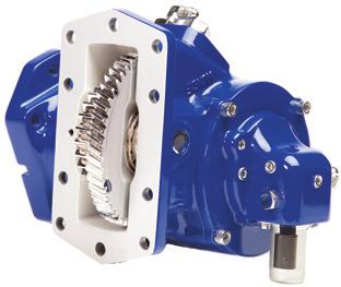
8 SECTION 2: THE PRIME MOVER SG Series The prime mover supplies the mechanical power to drive the hydraulic system. In the mobile hydraulics industry the prime mover we are most familiar with is the truck engine. The truck engine is frequently used to provide power through a Power Take-Off, through belts from the crankshaft pulley, or directly through a tubular driveshaft assembly. On some high horsepower systems an auxiliary, or pony engine might be used. In any case, the prime mover must be capable of providing the horsepower necessary to power the hydraulic system. Refer to the hydraulic horsepower formula on page 3. POWER TAKE-OFFS TG Series The original power take-offs were single gear models with a gear that slid into mesh with a transmission gear, resulting in output shaft rotation. Single Gear PTOs are limited by their speed and horsepower capabilities. You will find them used primarily on small, single axle dump trucks and agricultural hoists. CS24 Series Double, or Triple Gear, power take-offs, found on dump trucks, refuse vehicles, wreckers, aerial bucket trucks, tank trucks, and truck mounted cranes, are the most widely used type of PTO because of their versatility. This type of PTO can be engaged by cable, air, electric solenoid, or mechanical levers and a wide variety of output shafts and mounting flanges allow for direct coupling of hydraulic pumps from major manufacturers. PTO output shaft speeds can be changed by changing the internal gear ratio of the PTO. The newest design in power take-offs is the Clutch Shift type. These models engage by means of friction disks rather than sliding gears. Clutch type PTOs are commonly used on refuse, utility, and emergency equipment garbage trucks, aerial bucket trucks, and fire/rescue vehicles. FR Series 82 Series Power Take-Offs used to transfer engine power to a hydraulic pump. We will not attempt to go into PTO selection in this text. Suffice to say that when a power take-off is utilized as the source of power for the hydraulic system, it must meet the torque, horsepower, and speed requirements of the system. For more detailed information on PTO types, selection, and troubleshooting please refer to another Muncie Power Products publication, Understanding Power Take Off Systems. ENGINE CRANKSHAFT DRIVEN Many refuse and snow control vehicles utilize a front-mounted hydraulic pump driven by a tubular driveshaft assembly from the harmonic balancer of the engine. This live power arrangement has the advantage of providing full engine torque on high-demand applications while eliminating the cost of the power take-off. The disadvantage to this type of installation is in the requirement to raise, or core, the radiator to allow passage for the driveshaft; extend the front frame rails; and fabricate a mounting bracket for the pump. Crankshaft driven clutch pump. Drivelines used for this application must be of the balanced, tubular type, capable of transmitting high torque loads. The Spicer 1310 series or its equivalent is commonly specified. Solid bar stock should never be used in crankshaft drive applications. Maximum U-Joint Operating Angle A O = Shaft Length 5 6 Muncie Power Products, Inc.


9 Another important consideration is driveshaft angularity. Not only is it necessary to keep the angle shallow generally less than 7 but also to keep the pump input shaft parallel to the engine crankshaft within 1 1/2. Likewise, the yokes on each end of the shaft must be in phase, or aligned with each other. Failure to address any of these requirements will result in driveshaft vibration and damage to the pump. A PUMP AUXILIARY ENGINES Auxiliary engines, gasoline or diesel, are typically used only in applications requiring full engine horsepower and torque. In truck mounted applications this would include such things as large vacuum pumps and concrete pumps. Usually, one or more hydraulic pumps are coupled to the engine s output shaft. BELT DRIVEN PUMPS Belt driven pumps, or clutch pumps, are popular power sources for applications such as wreckers and bucket trucks. They also represent an alternative to a power take-off system on vehicles without PTO apertures or where access to the transmission PTO aperture is obstructed. The clutch pump is belt-driven from the crankshaft pulley through an electric clutch similar to that found on an automobile air conditioner compressor. Max Max Speed Angle (RPM) A TOP VIEW TRANSMISSION PTO PUMP Note: Solid shafting is not recommended for continuous operating speeds above 1000 RPM One important consideration in clutch pump applications is the horsepower limitation of the engine belts. Dual 1/2 inch, automotive type belts can transmit about 15 horsepower. Most applications will utilize two V-belts or a poly-v type belt to drive the pump. This belt limitation (and available space limitations) prohibits the use of large displacement pumps (greater than 2 1/2 cu.in.) in clutch pump applications. Serpentine belt drives can deliver horsepower comparable to that of two v-belts. Belt driven clutch pump. Changes in truck design and cramped engine compartments present challenges to clutch pump manufacturers. However, clutch pumps remain a popular option for hydraulic applications requiring flows of up to 15 gallons per minute. Clutch pump and bracket kit. Proper belt alignment and tension are critical to clutch pump performance. Muncie Power Products, Inc. 7
.")
 and pressure (PSI/bar) requirements.")


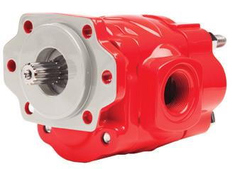
10 SECTION 3: PUMPS PUMPS PRODUCE FLOW PUMPS DO NOT PRODUCE PRESSURE PRESSURE RESULTS WHEN FLOW MEETS RESISTANCE Hydraulic pumps take the mechanical energy of the prime mover (a turning force) and convert it to fluid energy in the form of oil flow. As previously discussed, we normally refer to this oil flow in terms of gallons per minute (gpm). It is this flow rate which determines the speed at which a system will operate. If you have the manufacturer s specifications for the hydraulic system, they should state the operating flow (GPM/LPM) and pressure (PSI/bar) requirements. There may also be a suggested make and model for the pump. As far as the hydraulic system is concerned, any pump which will meet the flow and pressure requirements will work equally well. Some may be more efficient. Some may look different. The real cost may not be in the purchase price but in the cost of operating and maintaining the system over its life. Pumps may be of either a uni-rotational or bi-rotational design. Uni-rotational pumps are designed to operate in only one direction of shaft rotation while bi-rotational pumps can operate in either direction. Uni-rotational pumps are distinguishable in that the inlet and outlet ports are different sizes, with the inlet being the larger. Some bi-rotational pumps have two input shafts, to match the rotation of the driveshaft. Bi-rotational pumps also tend to have equally sized ports since either can be the inlet or outlet, depending on rotation. NOTE: If the pump is PTO driven the input rotation will be left-hand (CCW) if a manual transmission and right-hand (CW) if an automatic transmission. Ford automatics are the exception. POSITIVE AND VARIABLE DISPLACEMENT PUMPS Three types of hydraulic pump construction are typically found in mobile hydraulic applications: gear, piston, and vane. GEAR PUMPS Gear pumps are the most common design in use for truck mounted hydraulic systems. Gear pumps are relatively inexpensive, have few moving parts, are easy to service, and are generally more tolerant of contamination than other designs. Gear pumps are fixed, or positive, displacement pumps. That is, they produce the same volume of flow with each complete shaft rotation. The types of systems in which gear pumps are generally used are referred to as open center systems. Open center systems are those which allow oil to flow through the open center core of the directional valve and back to reservoir under low, return pressure when it is not being directed to a work function. Gear pumps can only be used in closed center systems if special unloading valving is utilized. Gear pumps operate by trapping oil in the areas between the teeth of their two gears (the drive gear on the input shaft, and the driven, or idler, gear) and the body of the pump, transporting it around the circumference of the gear cavity, and forcing it through the outlet port as the gears mesh. A small amount of pressurized oil is allowed behind brass alloy thrust plates, often referred to as wear plates, at each end of the gear set, pushing them tightly against the gear ends to improve pump efficiency. Gear pumps are rated in terms of their cubic inch displacement, maximum pressure rating, and maximum input speed limitation. Gear Pump cross section. 8 Muncie Power Products, Inc. Muncie gear pumps are available in displacements from 1/2 cu.in. to 14 cu.in. Pump manufacturers use a rating speed to describe their pumps. This allows them to describe their pump in the gallons per minute terms most users are accustomed to. A manufacturer using 1000 rpm as his rating speed would, for example, refer to his 7 cu.in. pump as a 30 gpm pump. (7 cu.in. X = 30.3 gpm). A manufacturer using 1200 rpm as his rating speed would refer to the same 7 cu.in. pump as a 36 gpm pump. (7 cu.in. X = gpm).
11 Caution: Not all pump manufacturers use the same rating speed. Some use 1000 rpm, some use 1200, and some use Care must be taken in comparing or replacing pumps from different manufacturers. You do not want to sell your customer a pump too large or small for his application because you did not make an accurate comparison. If possible, make your determination based on cubic inch displacement comparisons or the original equipment specification. All pumps, regardless of design, have a maximum pressure rating. This is the highest pressure at which the pump was designed to operate. It is not the pressure that the pump produces every time it is operating. The maximum operating pressure rating is affected by many variables including shaft diameter, bearing loads, body composition, port type, and port size. One major factor that affects pressure ratings of gear pumps is the distance between the front and rear bearings that support the pump s gears. The greater the unsupported length, the lower the maximum pressure rating. A pumps maximum operating speed is based, primarily, on the limit at which the rotating gears can fill the gear cavity before cavitation begins, although bearing type and the quality of the hydraulic oil can also be factors. Often this relates to port diameter and location. It can also be affected by hose size, reservoir location, and oil viscosity. Operating at excessive speeds can result in cavitation and/or heat damage. More on cavitation later. Interestingly, gear pumps also have a minimum speed limitation. Gear type pumps are generally most efficient in the upper third of their operating speed range. Pumps turned slowly are less efficient than those turned faster. Operating below the minimum RPM results in excess heat generation, which can damage seals and wear plates. Generally speaking, gear pumps should not be operated at input shaft speeds under 1000 RPM. The chart below shows a typical performance chart for a gear pump. Notice that at a constant pressure the pump s volumetric efficiency will increase as pump shaft speed increases. Notice also that at a constant speed efficiency will decrease as pressure increases. Changes in either speed or pressure will affect a gear pump s volumetric efficiency. Pumps operated in the upper end of their speed range are more efficient than those operated in the lower end. Keep this in mind when selecting the power take-off. PUMP OUTPUT FLOW BASED ON CUBIC INCH DISPLACEMENT-THEORETICAL Shaft Speed (RPM) DISPLACEMENT Formula: GPM = C.I.D. x RPM 231 S.A.E. Mounting/Shaft Sizes S.A.E. PILOT BOLT CIRCLE SHAFT SIZE A 3.25 (2) B 4 (2) spl. 4 (4) spl. BB 4 (2) spl. (4) spl. C 5 (2) spl. (4) spl. PILOT PUMP PERFORMANCE CHART MODEL: PK1-13 (2.96 cu. in. Displacement) TEST: Average pump test data TEMP: 120 F VISCOSITY: 100 SUS SPEED PSI BAR FLOW TORQUE INPUT HYD MECH VOL OA RPM OUT OUT GPM IN-LB FT-LB HP HP EFF EFF EFF 500 1, , , , , ,000 1, , , , , ,500 1, , , , , ,000 1, , , , , ,400 1, , , , , BOLT CIRCLES BC BC Muncie Power Products, Inc. 9


12 V Series Piston Pump PISTON PUMPS Piston type pumps are frequently used where high operating pressures are required as piston pumps will, as a rule, tolerate higher pressures than gear pumps of comparable displacements. Truck mounted cranes frequently utilize piston pumps. The downside comes in the form of higher initial cost, lower contamination resistance, and complexity. With more moving parts, closer tolerances, and stricter filtration requirements, piston pumps require more sophistication on the part of the equipment designer and service technician. Cross section of variable displacement piston pump A piston pump consists of a cylinder block containing pistons which, as they move in and out, draw oil from the supply port and force it through the outlet. The length of the piston s stroke is determined by the angle of a swash plate which the slipper end of the piston rides against. The cylinder block, containing the pistons, rotates with the pump s input shaft while the swash plate remains stationary. The total volume of the pump s cylinders determines the pump displacement. Piston pumps are available in both fixed and variable displacement designs. A fixed displacement piston pump has a non-adjustable swash plate angle and, like a gear pump, its output flow is directly proportional to input shaft speed.this type of piston pump, like the gear pump, is used in open center hydraulic systems. In some applications snow and ice control vehicles for example the hydraulic flow requirements will vary based on operating conditions and it may be desirable to vary system flow without varying engine (pump input) speed. In these applications a variable displacement piston pump is specified. With this design, the swash plate is not fixed and its angle is adjusted, through a compensator, by a pressure signal from the directional valve. If more flow is required, the swash plate angle changes to create a longer piston stroke thereby increasing the pump displacement. Variable displacement pumps are used in closed center systems. In these systems there is no excess flow or lost hydraulic horsepower because the swash plate angle decreases as the flow requirement diminishes. Variable displacement piston pumps may be either pressure compensated, flow compensated, or both pressure and flow compensated. A Pressure Compensated system is one which adjusts the swash plate angle (pump displacement) to maintain a specified flow regardless of changes in system pressure. A Flow Compensated system adjusts the swash plate angle to maintain a constant margin pressure as flow requirements change. A system with a combination of pressure and flow compensation is often referred to as a Load Sensing system. Many ice and snow control vehicles utilize this type of system. VANE PUMPS Cross section of vane pump Vane pumps, once common on utility vehicles aerial buckets and ladders are not as frequently found on mobile (truck-mounted) hydraulic systems today. The primary reason can be traced to the wide acceptance and availability of gear type pumps and the greater equipment control provided by variable displacement piston pumps. Vane pumps work similar to gear pumps in that as the input shaft rotates it causes oil to be picked up between vanes and transported to the pump s outlet side. However, there is only one set of vanes, as opposed to a pair of gears, on a rotating cartridge in the pump housing. The area between the vanes increases on the inlet side of the pump and decreases on the outlet. This change in area results in the oil being drawn in through the supply port and expelled through the outlet as the vane cartridge rotates. 10 Muncie Power Products, Inc.


 and are not suitable for other common trailer applications like live floor and ejector trailers.")


13 DUMP PUMPS The most recognizable truck pump is the Dump Pump. The dump pump, as we know it today, was introduced over 50 years ago and is little changed since, although the newest design offers larger ports and a more efficient gear design. This pump, common on dump trucks from tandem axle to dump trailers, is essentially a gear pump of slightly more than 6 cu.in. displacement with an integral three position, three way directional control valve, and pressure relief assembly. The most important thing to keep in mind about these pumps is that they were designed specifically for one application dump trucks (hence the name!) and are not suitable for other common trailer applications like live floor and ejector trailers. Narrow internal paths make them unsuitable for continuous duty applications due to the likelihood of excessive heat generation. Dump pumps also have maximum pressure ratings that may fall below the requirements of some live floor applications. For applications involving both dump and live floor trailers use the Muncie Combo Kit II System which utilizes a high pressure, continuous duty pump and separate high volume control valve with a two-stage relief assembly. Dump pumps are commonly direct-coupled to the power take-off. Weighing 70 lbs. it is vital that direct-coupled pumps be rigidly supported, via an installersupplied bracket, to the transmission case. This bracket should be a four-point (two pump/two transmission) type. Dump pumps provide extended assembly studs to use as attachment points. Refer to the PTO installation manual for additional information and design suggestions. The most important consideration in dump pump selection is two-line vs. three-line installation. This refers to the number of hoses used to plumb the pump. Two-line systems utilize a common inlet and return hose and are common on trucks that simply dump, rather than spread, materials. Three-line systems are equipped with a dedicated return hose and are preferred if the truck will be used for spreading applying gravel to a roadbed for example. A dump pump can easily be converted from two to three-line by inserting an inexpensive sleeve into its inlet port and un-capping the return port. The sleeve blocks an internal path and neutral/return oil is directed back to tank via the return port. There is one special concern; the third (return) line must be positioned below the tank s oil level to prevent loss of prime and subsequent pump aeration damage. 1 NPT (Return) 1 NPT (Cylinder) 1 1 /4 NPT (Inlet) E Series Pump (for dump bodies) DO NOT USE FOR LIVE FLOOR APPLICATIONS There are multiple benefits of a three-line installation over a two-line. The primary benefit is one of efficiency. The third line allows an unobstructed return path to reservoir resulting in faster cycle times. The second benefit is system protection should an operator inadvertently leave the PTO in gear and the pump turning while traveling down the road. The third is that the dedicated return line allows for the installation of a return line filter to remove contaminates; an important consideration, especially if trailers are frequently switched between tractors. TWO LINE INSTALLATION INLET TO PUMP PLUGGED PORT TO/FROM TANK TO/FROM CYLINDER INTERNAL FLOW PATHS Fig. 1 Fig. 2 Spool in Neutral: Oil recirculating within pump INLET TO PUMP FROM TANK TO/FROM CYLINDER DIFFUSER QUICK DISCONNECT (USED WITH DUMP TRAILERS) Body Lowering: Return oil flows around relief valve and returns via inlet (tank) port THREE LINE INSTALLATION Return Port RETURN TO TANK DIFFUSER QUICK DISCONNECT (USED WITH DUMP TRAILERS) IF OIL SPRAY FORMS AROUND THE BREATHER CAP ON A 3-LINE SYSTEM, THE TANK LINES MAY BE REVERSED. INTERNAL FLOW PATHS Fig. 3 Fig. 4 Sleeve Spool in Neutral: Oil circulates through pump and returns through 3rd port in pump Return Port Sleeve Body Lowering: Return oil flows through 3rd (return) port Muncie Power Products, Inc. 11

 front crankshaft driven pumps used primarily on refuse equipment.")


14 PUMPS FOR REFUSE VEHICLES: Both Dry Valve and Live Pak pumps conserve fuel while in the Off mode, yet provide full flow when work is required. Both are based on standard gear pump designs with additional, special valving incorporated. Dry Valve Pumps Power-Pro Pump Dry Valve pumps are large displacement (6-9 cu.in.) front crankshaft driven pumps used primarily on refuse equipment. Dry valve pumps utilize a special plunger-type valve in the pump inlet port to restrict flow in the OFF mode and allow full flow in the ON mode. This lowers horsepower draw and saves fuel when the hydraulic system is not being used. The dry valve, in its closed position, allows only enough oil to pass to maintain pump lubrication. This lube oil, about 1 1/2 gpm, is returned to reservoir via a bleed valve and small return line. A fully functioning bleed valve is crucial to the life of the dry valve pump. Cavitation induced pump failure will result if a bleed valve becomes clogged with contaminates. Muncie also manufactures a butterfly-style dry valve, called a Power-Pro valve, which eliminates the bleed valve requirement and provides for improved system efficiency. Note: The wearplates and shaft seals for a dry valve-type pump differ from the standard gear pump parts. Attempting to fit a dry valve to a standard gear pump will likely result in premature pump failure. Live Pak Pumps Powr-Miser Pump Bleed Valve Like dry valve pumps, Live Pak pumps are used primarily on refuse vehicle applications. Unlike dry valve pumps, Live Pak pumps do not have their inlet fitted with a shutoff valve. Instead, their outlets incorporate a flow limiting valve, called a Live Pak valve, which acts as an unloading valve in the OFF position and a flow limiting valve in the ON position. This has the effect of limiting the hydraulic system speed to keep it within safe operating parameters. These pumps also are typically engine crankshaft driven. Live Pak Pump Dry Valve Wear Plate Standard Wear Plate 12 Muncie Power Products, Inc.


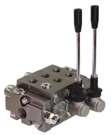
15 SECTION 4: DIRECTIONAL VALVES As their name implies, directional control valves direct the oil flow produced by the pump to the various actuators (cylinders and motors) of the system and/or back to tank. As previously discussed, there are two types of hydraulic circuits, open center and closed center. These circuits require very different directional valves. Open center valves, found on dump trucks, refuse vehicles, wreckers, and most other truck mounted applications, have a passage, called the open center passage, or open center core, to a return port which directs unused oil flow back to tank. Open center valves are used in systems with fixed displacement pumps. Closed center valves, frequently found in central hydraulic systems for ice and snow control vehicles and some utility equipment, are used with variable displacement piston pumps and do not have this open center passage. V130 Series Valve Directional valves can be of two construction types, monoblock and sectional. The monoblock valve is one which has been machined from a single casting and contains the valve s inlet, work, and return porting in a single block. The sectional, or stack, valve is more versatile, having separate inlet, work, and return sections that can be configured to suit any application. Sectional valves are popular with hydraulic component distributors because of their versatility and serviceability. Besides being discussed in terms of open or closed center, valves are also described in terms of their spool positions and flow paths, ie: 3 position, 4 way. In this example 3 position refers to the raise, neutral, and lower positions of the valve spool. 4 way refers to the internal flow paths of the work section: (1) in from supply, (2) pressure to extend, (3) pressure to retract, and (4) a return to tank. Valves with two spool positions are typically selector valves used to direct oil flow to either of two hydraulic circuits. The directional valve we are most accustomed to in mobile hydraulics is the three position raise, neutral, lower type. Three-way valve sections are used to control single acting, power up, gravity down hydraulic cylinders. Four-way sections control double acting, power up, power down cylinders. A special type of four-way valve section, called a free flow or motor section is used to supply oil flow to a hydraulic motor. This section differs from the standard four-way section in that the spool is machined to allow crossover flow between the work ports and the return core of the valve while in the neutral position. This prevents movement of the driven component from damaging the motor. Directional control valves are specified according to the volume of oil flow they must carry, operating pressure, and number and type of work sections required. Valve manufacturers specify nominal and maximum flow rates as well as maximum operating pressures. The nominal flow is the flow rate at which the valve reaches peak efficiency. The maximum flow and pressure are not to be exceeded least damage, often in the form of excess heat generation, occur. In OPEN CENTER systems there is constant flow and intermittent pressure. In CLOSED CENTER systems there is constant pressure and intermittent flow. V080 Series Valve All valves have an inlet section, which receives flow from the pump and often is equipped with a system pressure relief cartridge, one or more work sections to direct flow to the actuators (cylinders and motors), and a return section to direct oil back to the reservoir. The work sections are specified according to the function of the actuator; single acting, double acting, or motor. In addition, the work sections can be equipped with one or more options such as individual port relief cartridges, flow restrictors, or anti-cavitation valves. Individual port relief cartridges allow for some work ports or valve sections to have different pressure relief settings than the other system functions. This option is commonly specified for the down stroke of a double acting dump body cylinder. Flow restrictors are used to limit flow and, thereby, actuator speeds. Anticavitation valves will prevent cylinder cavitation in double acting cylinders caused by excessive speed in the down stroke. Another option is the Power Beyond or High Pressure Carryover (HPCO), used to route pressurized oil downstream to another valve. Muncie Power Products, Inc. 13


.")
16 Each work section in a directional control valve also has multiple spool action or back cap options. These include: spring centering; 3-position detent; 4-position detent; magnetic release and so on. Directional control valves can be shifted with short handled levers, cable controls, lever linkage, direct or pilot operated solenoid controls, hydraulic controls, or pneumatic controls. These all tend to be customer preference options but are largely influenced by valve location and climate. SECTION 5: OTHER VALVES Other valves used in mobile hydraulic circuits include Flow Dividers, Selector Valves, and In-line Relief Valves. PFD-30 Priority Flow Divider Flow Dividers are used to split the flow produced by a single pump so that two systems can operate simultaneously. Flow dividers can be either proportional or adjustable. Proportional flow dividers will split the incoming flow, regardless of flow rate, on a proportional basis (50/50, 75/25, etc.). Adjustable flow dividers, sometimes called priority flow dividers, by means of an adjustable, pressure compensated orifice, set the flow to the primary, or controlled, outlet, with the balance of the flow directed to the excess flow outlet. This type is commonly used to limit the speed of a hydraulic motor or cylinder by allowing no more than a set volume of oil flow to reach it. Selector Valves are used to direct all oil flow to one circuit or another, rather than splitting it into two paths. The basic selector valve is a two position, three-way valve. This valve is frequently used on dump trucks that pull a separate, pup trailer. In-Line Relief Valves, as the name implies, are auxiliary relief valves that can be mounted anywhere on the pressure side of the circuit. They can be used to isolate a part of the system, to provide pressure protection to individual components, or to supplement the main system relief. MSV Selector Valve Relief valves can be of either the direct acting or pilot operated type. In a Direct Acting relief, the system pressure pushes against a spring loaded plunger. When system pressure exceeds spring tension the valve opens and pressure is relived to reservoir. Pilot Operated relief valves utilize system pressure along with spring tension to create a smoother acting, more accurate valve. Typically relief valves should be set approximately 15% above the equipment manufacturer s recommended operating pressure. Setting the relief pressure too close to operating pressure can result in premature and unnecessary relief valve functioning. This can, in turn, create noise and heat problems as well as erratic operation. Remember, oil passing over the small orifice of a relief valve is a common cause of system overheating. This occurs when a valve is improperly adjusted or is sticking due to trapped contaminates. The relief line going back to tank must be of sufficient diameter to carry the flow. If the relief valve or line is too small it is possible to force flow into the system by saturating the relief valve. This condition can easily result in system damage. RV-30 In-line Relief Valve Always check relief valve settings when replacing a pump as it is common practice for inexperienced mechanics to attempt to correct for lost pump efficiency by turning up the pressure. The relief valve should never be adjusted unless there is a pressure gauge installed to determine the proper setting. 14 Muncie Power Products, Inc.

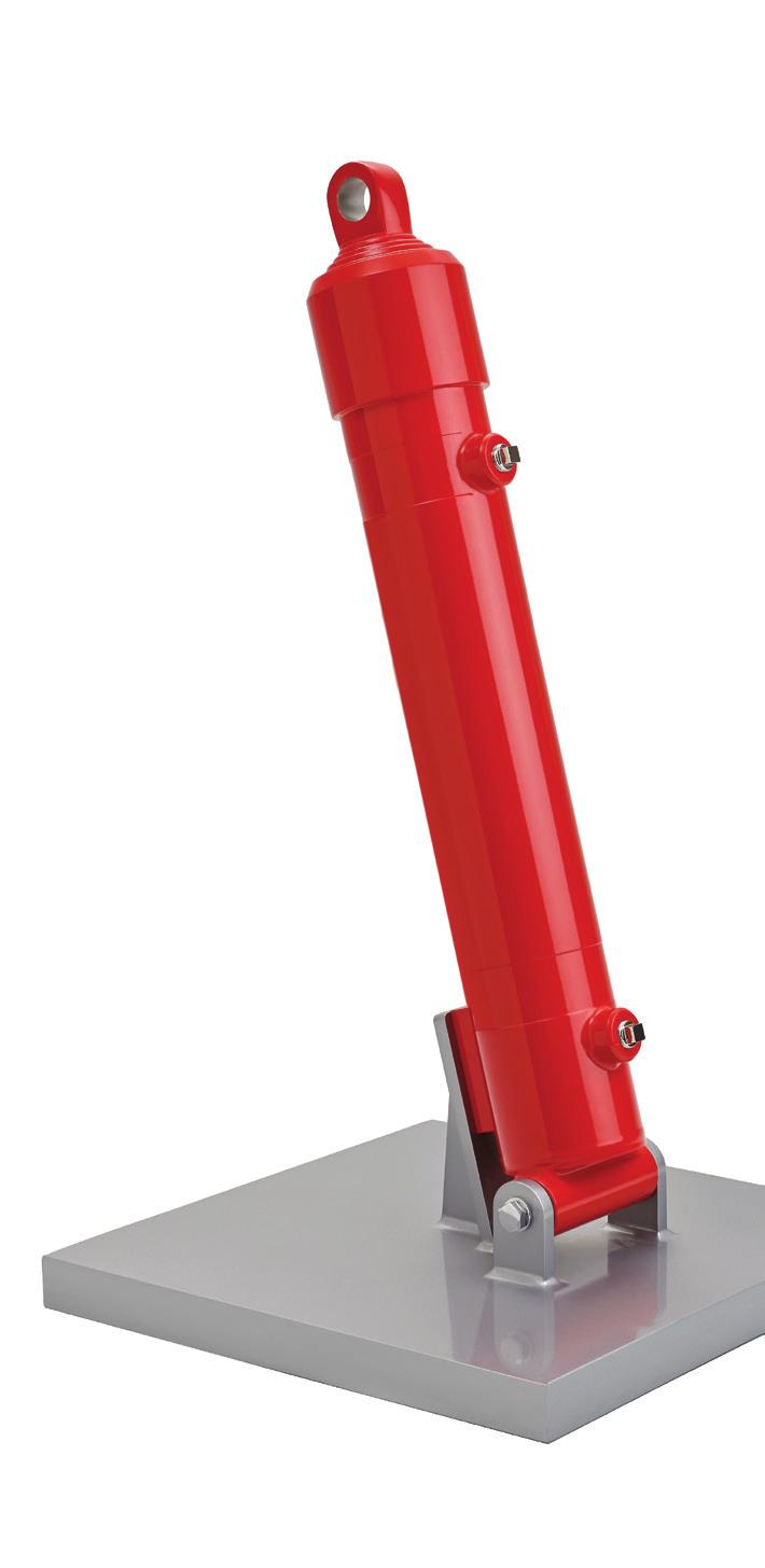
17 SECTION 6: ACTUATORS The actuators are the hydraulic components that actually perform the physical work in the system. They are the components that convert fluid power into mechanical power. Hydraulic cylinders and motors are the system actuators. Hydraulic cylinders convert fluid power into linear motion to raise a dump body or angle a plow, for example. Hydraulic cylinders may be single acting or double acting; single stage or multiple (telescopic) stage. Single acting cylinders, also referred to as power up/gravity down type, are extended by supplying flow to the base of the cylinder, pushing the cylinder s piston, and extending the rod. The single acting cylinder relies on an opposing force, weight and gravity, to retract. This type of cylinder is commonly found on dump bodies and snow plow lifts. Most telescopic cylinders are single acting. Cap Cap end fixed clevis Cushion cavity Port Barrel Cushion spear Typical Cylinder Construction Cut-away drawing of double-acting cylinder illustrates basic parts. This particular example shows clevis mounts to accommodate load that moves in an arc, similar to a dump body. Piston Stop tube Piston Seal Rod Cushion nose Port Head Check Valve Rod clevis Variable orifice Double acting, or power up/power down, cylinders are hydraulically powered in both directions. Double acting cylinders are used where the cylinder will be mounted in a horizontal position or where greater control of the return stroke is desired. Snow plow angling and crane arms are common truck mounted applications. While most double acting cylinders are single stage, there are applications which require the longer stroke of a telescopic cylinder. Telescopic Cylinder Pressure = Force Area The theoretical hydraulic system pressure required to move a hydraulic cylinder can be calculated by dividing the load (weight to be lifted) by the area of the hydraulic cylinder s piston. Notice that this is the theoretical pressure requirement. In actuality, to begin movement from a standstill approximately 30% more pressure is required. To accelerate movement approximately 10% more pressure is required. This added pressure is necessary to overcome friction within the cylinder. Obviously, other factors come into play in determining pressure requirements. Is the load being lifted straight up or pivoted, as in a dump body application? If the load is being moved horizontally, what frictional forces must be overcome? Does the load shift during cylinder travel? How fast does a hydraulic cylinder extend or retract? If you desire to extend a cylinder in a given amount of time, how much flow will be required of the pump? How does pump efficiency affect cylinder speed? All of these questions can be answered by a simple calculation. Remember your basic high school geometry class and the formula πr 2? You used it to calculate the area of a circle. The π, or pi symbol stands for 3.14, r is the radius (1/2 the diameter) of a circle, and to square a number (x 2 ) means to multiply it times itself. The formula then is r X r X 3.14 to get the area that is referred to in the above formula. This would be the surface area of the hydraulic cylinder s piston in square inches. With the piston area known, you can determine the rate of extension of the cylinder by using the formula: GPM X 231 Area = Cylinder velocity in inches per minute F Force P Pressure A Area F = P x A P = F A A = F P All hydraulic applications are governed by the relationship of Force, Pressure and Area. CYLINDER FORCE CAPACITY FIGURES IN THE BODY OF THE CHART ARE THRUST VALUES IN POUNDS PISTON OR AREA ROD DIA SQ IN PSI PSI PSI PSI ,603 14, ,432 19, ,566 18,849 25, ,726 19,635 29,452 39, ,205 28,274 42,411 56, ,864 38,485 57,727 76, ,699 50,265 75, , ,713 63,617 95, , ,909 78, , ,080 To take this one step further, once you determine the area of the cylinder s piston, the volume of the extended cylinder can be calculated by multiplying the piston area by the length of the stroke and dividing by 231. Using a 6 diameter cylinder as our example we would calculate a volume of 4.4 gallons if the length of the cylinder s stroke were 36 inches X = 4.4 gallons Muncie Power Products, Inc. 15
18 CYLINDER EXTENSION SPEED INCHES PER MINUTE Piston Diameter PUMP FLOW (GPM) Example: 8 gpm is sent to a 6 diameter hydraulic cylinder. How fast will it extend? The area of the piston is sq. in. (πr 2 ) 8 gpm X sq. in. = inches per minute of rod travel. If you don t see your cylinder in the chart at the right, use the factors below to determine fill and extension requirements. CYLINDER CAPACITY FACTORS Cylinder Size Fill Extend Dia./ No. Stages Factor Factor 5 / 3 stage / 3 stage / 3 stage / 4 stage / 4 stage / 5 stage / 5 stage ie: A 7 dia., 4 stage cylinder with a 144 stroke will require 5.04 gal. to fill and gal. to extend. 144 X.035 = 5.04 gal. 144 X.106 = gal. If we wish to fully extend this cylinder in one minute we would require a pump flow rate of 4.4 gpm. To extend it in 30 seconds a flow rate of 8.8 gpm would be necessary (twice the flow = twice the speed). If we are using a fixed displacement pump to provide the flow, we must turn it at twice the input speed to achieve twice the output flow. If we are using a power take-off to provide power to the pump we must then run the engine at twice the speed. An alternative would be to change the power take-off to a faster (2X) model. Yet another alternative would be to replace the hydraulic pump with a model of twice the cubic inch displacement. Things get a bit trickier when working with multiple stage, telescopic cylinders. How do you determine extended cylinder volume when you have three, four, or five successively smaller cylinder sections to extend to reach an overall extended length? See the chart below to get an estimated volume for various common sizes of telescopic cylinders. Two capacities are shown, Fill and Extend. The Fill capacity represents approximately how many gallons are required to fill the empty cylinder before it begins to move. (This will only apply the first time the cylinder is extended, thereafter these areas will contain oil.) The Extend capacity represents the volume of oil required to fully extend the cylinder. This information is also available from the hydraulic cylinder manufacturer or distributor. Cylinder maintenance and troubleshooting. When first installed, hydraulic cylinders must be bled to remove air. Air trapped in a cylinder will cause the cylinder to move in a jerky manner as air, under pressure, will compress. The compression of air in a hydraulic system also creates heat. Cylinders are equipped with a bleed screw to facilitate the removal of air. Air can get into a cylinder, and oil can leak out, if the packing seals become damaged or if the rod becomes rust pitted or scored by contaminates. Watch a telescopic cylinder extend and retract. Extension should always begin with the largest diameter section and progress to the smallest. If it does not, there is a problem with the cylinder, not the pump. Retraction should be just the opposite; smallest section first, largest last. HYDRAULIC CYLINDER CAPACITY REQUIREMENTS DIAMETER NUMBER LENGTH GALLONS GALLONS OF LARGEST OF OF REQUIRED REQUIRED MOVING STAGES STROKE TO FILL TO EXTEND STAGE (APPROX) (APPROX) Muncie Power Products, Inc.


19 Cylinders that have to control heavy loads are sometimes equipped with a counterbalance valve to prevent the cylinder from bleeding down or retracting too rapidly, creating a dangerous operating condition. The counterbalance valve is typically non-adjustable to prevent tampering and allows for greater operator control of the loaded cylinder. Cylinders should be stored in a vertical position to prevent seal distortion and with their ports plugged to keep contaminates out. Hydraulic motors, commonly referred to as torque motors, convert fluid energy into rotary mechanical energy just the opposite of a hydraulic pump. In fact, if equipped with the proper shaft seal and a case drain port, a pump can sometimes be used as a hydraulic motor. Motors are broadly classified as either high-speed/low-torque motors, or lowspeed/high-torque motors. The latter, also called a gerotor motor, is the type we are probably most accustomed to. This is the type that is commonly used for hydraulic winch drives, turrets for cranes or aerial ladders, or auger drives. These motors typically operate at speeds ranging from less than 100 revolutions per minute upward to 800 rpm. The gerotor design has the advantage of multiplying torque within the motor, making it an excellent choice for applications requiring high start-up torque. This is also the type used for wheel drives. Geroler Design High-speed/low-torque motors will operate at speeds ranging from 800 to 3000 rpm. Gear pumps are often used as high-speed motors. When used in this fashion the outlet, or high pressure port, becomes the inlet and visa versa. A case drain port, plumbed to reservoir, relieves pressure behind the shaft seal. Hydraulic motors, by their nature, are inefficient and can generate a great deal of heat, particularly if the duty cycle is long. These applications often require the use of oil coolers to keep operating temperatures at acceptable levels. To properly select a hydraulic motor it is necessary to know the speed at which the motor shaft must turn and the horsepower it must deliver. Muncie Power Products, Inc. 17


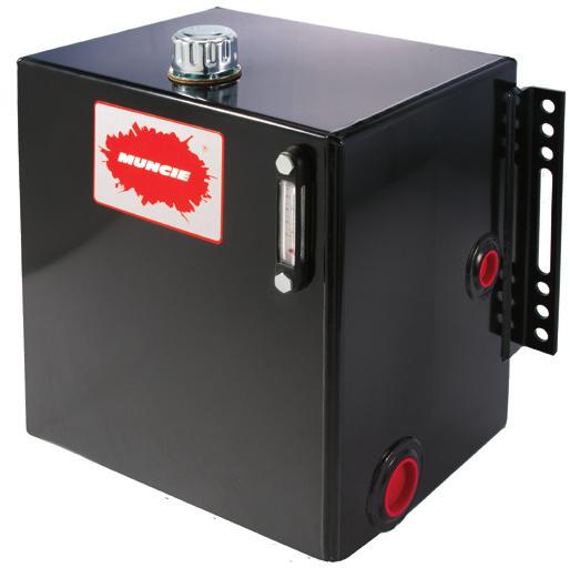
20 SECTION 7: RESERVOIRS Reservoirs serve three purposes in the hydraulic system: they store the oil until the system requires it, they help provide for the cooling of the oil, and they provide a place for contaminates to settle out of the oil. Material, volume, location, and shape are important considerations in selecting a hydraulic reservoir. Oil reservoirs can be constructed from steel, aluminum, or polyethylene plastic. Each of these materials has benefits and drawbacks which should be considered when selecting a reservoir. 35 Gallon Steel Reservoir Steel reservoirs are good dissipaters of heat and are relatively easy to construct. Steel plate is readily available and inexpensive. However, steel reservoirs are susceptible to moisture condensation and rust. Also, it is not uncommon to find welding slag and splatter, which can damage system components, inside steel reservoirs. Steel is also heavy. Aluminum is both an attractive material and an excellent dissipater of heat, providing three times the heat transfer rate of steel. It is the choice of owner operators who equip their trucks with custom paint jobs and every imaginable option. But aluminum is expensive and requires a higher level of skill on the part of the fabricator. It is common for fabricators to split a 100 gallon fuel tank using half for fuel and half for hydraulic fluid. This situation presents numerous potential problems: the fluids must remain isolated; diesel fuel can be mistakenly added to the hydraulic oil; and there is often no design provision (diffuser) to help manage high volume return flow as in the case of a dump trailer. Also, condensation can cause aluminum to oxidize. Polyethylene plastic poly reservoirs are light in weight and can be molded in various shapes and even colors. The manufacturing process does not generate contamination particles and poly is less susceptible to moisture condensation. However, polyethylene is not a good dissipater of heat and should not be used for long duty cycle applications like hydraulic motor drives or live floors. Use it instead for dump, roll-off, or ejector type applications which have short duty cycles. 50 Gallon Polyethylene Reservoir Reservoir Size and Placement How large does a reservoir need to be to ensure an adequate supply of oil? There are two rules of thumb that can be used as a starting point. If the hydraulic system uses cylinders as its actuators, the reservoir capacity should equal the volume of oil required to extend the cylinders plus 20% (or four to six inches) reserve in the tank. If the system utilizes hydraulic motors as actuators, the reservoir capacity should equal twice the operating system flow rate. These rules are not absolute; they are affected by such factors as ambient temperature, length of duty cycle, frequency of use, etc. Remember, the goal is to keep an adequate supply of oil and to keep it cool. Placement of the reservoir is important. The primary job of the reservoir is to provide oil to the pump. Therefore, the ideal location is close to and directly above the pump s inlet port. While possible in an industrial setting this is often impossible to achieve in a truck mounted system. When the pump is mounted on the front of the vehicle or on top of the engine, the reservoir outlet is likely to be several feet away and below the pump inlet. In these conditions it is important that the inlet hose be oversized and kept as straight as possible to prevent cavitation of the pump. In some cases it may be necessary to use a sealed, pressurized reservoir. 55 Gallon Aluminum Reservoir Construction considerations The reservoir must be able to breathe, to take in and exhaust air as the fluid level changes. Therefore, it is important that the reservoir be equipped with a vent or breather cap. An improperly vented reservoir can starve the pump, so clean the breather frequently. 18 Muncie Power Products, Inc.
, which can then enter the system resulting in sluggish or jerky operation.")


21 The reservoir should be constructed so that returning oil flow always enters the tank below the oil level, either by placing the return port at the bottom or by directing the oil through a stand pipe to the bottom. Oil entering above the fluid level may create foam and air bubbles (aeration), which can then enter the system resulting in sluggish or jerky operation. A diffuser will further dissipate oil flow below the fluid level. Diffusers effectively manage high volume return flows common with dump applications. Reservoir Features BREATHER FILLER Another important design consideration is tank port placement and size. The pump inlet and return ports should be on opposite ends of the reservoir to allow the returning oil to lose heat before again being drawn into the system. To further keep the warmer, returning oil away from the pump inlet port and to help prevent sloshing, tanks may be equipped with baffles. Baffles should be located so as to direct the returning oil toward the walls of the reservoir where heat can be transferred to the atmosphere. The oil should take the longest possible route to the tank s outlet port. To keep settled contaminates from entering the system the tank outlet port should be raised slightly from the reservoir bottom. Low profile tanks may be attractive from the standpoint of ground clearance but can expose the pump inlet to atmosphere when operating off-road or on an incline. In addition, pump vacuum may create a vortex and draw air into the system. Temperature and fluid level gauges, fill screens, clean-out ports, and magnetic drain plugs are useful options for hydraulic oil reservoirs. To improve inlet conditions in piston pump systems pressurized reservoirs are frequently used. Three to four psi is normal for these applications. Calculating reservoir capacity is a matter of simple geometry. For square or rectangular tanks multiply the length (in inches) by the height, by the width. This will yield the volume in cubic inches. Convert it to gallons by dividing by 231. ACCESS/ CLEAN OUT PORT BAFFLE RETURN PORT (DIFFUSER OPTIONAL) 6 AIR SPACE TO FLOOR INTAKE PORT For cylindrical reservoirs we use the same formula that we used to determine the fill volume of a hydraulic cylinder, πr 2 X length 231 = gallons. Note: The above example does not consider the reservoir wall thickness, which will take away slightly from the actual capacity; along with the air gap; baffles or support structure; port size and location; or minimum oil level above the port to prevent uncovering or a vortex affect. Subsequently, the useable capacity of a reservoir is considered to be 80% of its total calculated volume. Square/Rectangle Example: The reservoir dimensions are 30 inches long by 24 inches tall by 20 inches wide. What is the capacity? 30 X 24 X = 62.3 gal. Cylindrical Example: The reservoir is 30 inches long and has a diameter of 24 inches ( r would =12). What is the capacity? 3.14 X 144 X = 58.7 gal. Muncie Power Products, Inc. 19


22 SECTION 8: OIL FILTERS It has been estimated that between 70% and 90% of hydraulic system failures are the result of contamination. Filters, properly selected and maintained, will prevent contaminates from damaging hydraulic components and enable the system to run cooler, quieter, and longer. Filters may be located in the pump s inlet, pressure, or return line. Suction strainers are located inside the reservoir and are useful in catching large objects like welding slag, shop rags, bolts, hand tools, and rocks. The typical strainer consists of a 100 mesh screen. This is a return line (discharge) filter which had mistakenly been installed on the intake side. Vacuum collapsed the inner structure of this element. The pump was destroyed in seconds. Suction filters, located between the reservoir and pump, offer the attractive benefit of filtering the oil before it reaches the pump. A good theory that may not work out so well in practice if the filter element is not properly selected and changed regularly. Remember, it is important that the pump inlet not be restricted and anything, including a filter, on the inlet side adds to the work the pump must do to draw oil from the reservoir. Some piston pump applications may require a 3µ suction filter and either a charge pump or pressurized breather cap. The rule of thumb for sizing a suction filter size is 4 times system flow. Pressure filters are located on the outlet (pressure) side of the pump and prevent wear generated contaminate particles from entering valves, cylinders, and motors. The addition of pressure accelerates the damage that contaminates cause. Pressure filters are expensive, however, and in mobile applications are mainly found in closed center, piston pump systems. Return filters are the most common type found in truck mounted hydraulic systems. Return filters are readily available, inexpensive, and easy to service. Replacement canister elements are often interchangeable between manufacturers. The most common is a 10 micron, spin-on type. The rule of thumb for filter size is to specify the filter for 2 times system flow. Filter carts, sometimes referred to as off line filters, are useful for removing contaminates from new oil ( new does not always mean clean ) and as part of a preventative maintenance program to prevent contamination damage. These filter systems remove the oil from the system, run it through filters, and put it back clean and ready to go. This process is sometimes referred to as Kidney Loop Filtration. Muncie Filter Family 20 Muncie Power Products, Inc.
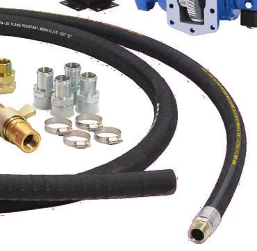
23 SECTION 9: HOSE AND FITTINGS Hydraulic hose must be the proper size and type to carry the oil at the specified rate of flow and pressure. Undersize hoses create unnecessary restriction, contributing to excessive neutral system pressures and added heat. Using the wrong hose for the application can result in leakage or bursting under pressure or, on the inlet side of the pump, to cavitation. The Society of Automotive Engineers (S.A.E.) has designations for hydraulic hose based on their intended usage and the fluid to be carried. The designations we are most concerned about for truck mounted hydraulic systems are S.A.E. 100R4, 100R1, 100R2, and 100R9. These designations can be found printed at regular intervals on the lay line of the hose. Also, hoses have maximum recommended oil velocity ratings based on their location in the system. Oil velocity is expressed in feet per second (FPS) and should not exceed the following: Inlet hose- 4 FPS Return hose- 8 FPS Pressure hose- 15 FPS Velocity can be calculated by the formula: V = GPM X.3208 A, where GPM is the flow rate and A is the inside area of the hose. S.A.E. 100R4 is suitable for the inlet side of the hydraulic pump. This type of hose has an inner tube securely bonded to a spiral wire wrap covered by a reinforcing layer. This prevents the hose from collapsing under the vacuum found in an inlet condition, something that more expensive pressure hose is prone to do. S.A.E. 100R1 hose contains a single wrap of braided wire and is suitable for low pressure return hoses. This hose can collapse under a vacuum condition and should not be used on the inlet side of the pump. This type of hose is often referred to as single wire hose. S.A.E. 100R2 hose ( two wire hose ) has two layers of wire wrap and is capable of handling higher system pressures. Use it between pumps and valves and between valves and actuators. S.A.E. 100R7/100R8 hose is a specially constructed, non-conductive, hose often used in aerial bucket applications for obvious safety reasons. It is easily recognized by its bright orange color. S.A.E. 100R9 rated hose is also a high pressure hose having multiple wire braid layers. The pressure rating for a particular hose is dependent on both the S.A.E. type and the size of the hose. You may note in the chart shown that as the hose diameter increases the pressure rating decreases. Hose has two pressure ratings, working and burst, with a safety factor of 4:1. That is, a hose with an 8000 psi burst pressure will have a 2000 psi working pressure. SAE 100R9 H.P. SAE 100R1 RETURN SAE 100R2 PRESSURE SAE 100R4 INLET Common Hose Types r Area = πr 2 Hose sizes are based on a dash size system wherein -16 is equal to one inch. Thus an S.A.E. 100R1-16 is a low pressure return hose with an inside diameter of one inch. An S.A.E. 100R4-24 is an inlet hose with an inside diameter of 1 1/2 inches and an S.A.E. 100R2-12 is a high pressure hose with an inside diameter of 3/4 inch. HOSE WORKING PRESSURES Hose Size 3/8 (-6) 1/2 (-8) 3/4 (-12) 1 (-16) 1 1/4 (20) 1 1/2 (-24) 2 (-32) Hose Type Maximum working pressure* S.A.E. 100R S.A.E. 100R S.A.E. 100R S.A.E. 100R S.A.E. 100R * Note: Minimum burst pressure is 4X maximum working pressure. Muncie Power Products, Inc. 21


24 Poor Design Movement causes twisting Poor Design Make hose assemblies long enough and routed in a manner that prevents exceeding minimum bend radius recommendations. Poor Design Good Design Movement flexes hose but does not twist Left-hand drawing shows how hose twists because it is bent in one plane while oscillating motion bends in a second plane. Rerouting the hose eliminates multi-plane bending. Good Design Good Design To prevent excessive strain at hose-to-coupling interfaces, hose assemblies should be made long enough to allow contraction and expansion. Hose routing tips: Do not exceed the manufacturer s recommended minimum bend radius of the hose. Do not allow a hose to be twisted. Mounting a hose with a 10 degree twist can shorten the life of the hose by as much as 90%! Never allow the outside bend of a hose to face the machine operator. Route hose so that it flexes in only one plane. The printed lay line of the hose should stay in one plane. For long runs, tubing or piping is often used. Besides being an economical method, metal tubing has the added benefit of improved heat dissipation. Always confirm that the chosen tubing is capable of withstanding the system operating pressures. Galvanized or black pipe is not recommended for several reasons, pressure being one. At a standard safety margin of 4:1, one inch diameter schedule 40 pipe has a working pressure rating of only 1450 psi and schedule 80 a rating of 2500 psi, marginal at best. Also, the galvanized coating can flake and create contaminates. Finally, the inside of the pipe is rough, adding to fluid turbulence, pressure drop, and heat generation. Remember, hose is measured on the inside diameter, tubing and pipe on the outside. Pipe thread fittings (NPT) are common, primarily due to cost and availability. They are, however, probably the worst choice for a hydraulic system. In order to make them seal, installers will routinely use teflon tape, pieces of which can clog small passages and cause valves to malfunction. There are also dangers in overtightening NPT fittings, particularly if teflon tape is used, and damaging pump and valve castings. A far superior choice is; o ring face seal fittings; S.A.E. 37º (J.I.C.) flare fittings; or the straight thread, o ring type (U.N.F.). These allow for better positioning of hoses and will seal without the use of tape or liquid thread sealant. Another advantage of these fittings is that they are reusable. Pipe thread fittings, which only seal as threads are deformed, should never be re-used. Fitting Torque Values for NPT (Pipe) Fittings THREAD SIZE ASSEMBLY TURNS 1/ / / /4 1½ - 2½ 1¼ 1½ 1½ - 2½ 1½ - 2½ Tighten the fitting finger tight, mark with a line, then tighten the indicated number of turns. PASTE ONLY, DO NOT USE TEFLON TAPE Fitting Torque Values for Straight Thread (UNF) Fittings TUBE O.D. LINE SIZE TORQUE (lb.ft.) Muncie Power Products, Inc.
25 Fitting Torque Values for JIC 37º Flare Fittings Fitting Torque Values for S.A.E. Flange Fittings LINE SIZE ROTATE NO. OF FLATS -04 1½ - 1¾ ½ ½ -08 1¼ - 1¾ -10 1¼ - 1¾ ½ -16 ¾ ½ - ¾ -24 ½ - ¾ -32 ¾ CONNECTOR SIZE TORQUE (lb.ft.) Tighten the fitting finger tight, mark with a line, then tighten the indicated number of flats. Bending Radius HOSE TUBE The bend radius of hose is measured to the outer wall of the inside of the bend. The bend radius of tubing is measured to the center of the tube. Hoses and fittings must be sized to handle the system flow at the highest anticipated operating speed. Calculators and charts are available to assist in determining the correct hose size. Do not base the hose size just on component port size. This is an extremely common, but erroneous practice. Restrictions accumulate over distance. Base hose size on maximum flow rates FLOW (GALLONS/MINUTE) HOSE CHART BASED ON FORMULA GPM x AREA (SQ. IN.) = VELOCITY (FT./SEC.) NOMINAL STANDARD PIPE SIZES ACTUAL INSIDE DIAMETER OF PIPE, TUBE AND HOSE (INCHES) / / / /4 1 1 /2 1 1 /4 1 7 /8 3 /4 5/8 1/2 3/8 1/4 1/ MAXIMUM RECOMMENDED VELOCITY FOR INTAKE LINES MAXIMUM RECOMMENDED VELOCITY FOR RETURN LINES MAXIMUM RECOMMENDED VELOCITY FOR PRESSURE LINES AREA OF PIPE, TUBE & HOSE (SQ. IN.) VELOCITY (FT./SEC.) Muncie Power Products, Inc. 23
26 HYDRAULIC FLUID RECOMMENDATIONS FOR GEAR PUMPS Max. Intermittent SSU (1620 cst) Max. Continuous SSU (216 cst) Min. Continuous...60 SSU (10 cst) Max. Temperature Production Seals Intermittent Continuous OIL TEMPERATURE: Pumps and components such as bearings and oil seals will be affected by high heat. Cool operating temperatures (below 130 F) will produce conditions which result in extended oil life, providing target SSU is met. SSU: Saybolt Seconds Universal The number of seconds required for 60ml of a fluid to pass through an orifice of a given size at one atmosphere at a controlled temperature. If no temperature is stated, it is assumed as 100 degrees F [38 degrees C.] Viscosity Index [V.I.] is an indication of a fluid s rate of change. cst: Centistokes System temperature is the result of many factors, including: Overall system efficiency Reservoir size and location Proximity of components to heat sources Duty cycle Level of contamination Quality of oil Ambient temperature To lower operating temperatures: Review component selection for undersized components. Increase reservoir capacity. Shield components and hoses from exhaust systems. Keep oil clean. Install an oil cooler. SECTION 10: HYDRAULIC OILS Oil must serve several functions within the hydraulic system; deliver power, lubricate components, dissipate heat, and carry away contaminates. To perform these functions hydraulic oils contain specific additives to enhance their ability to stand up under the pressure, temperature extremes, and other operating conditions to which they are subjected. To a large extent the life of the hydraulic system is directly tied to the life of the oil. If oil is kept clean and below 140 F the entire system benefits. Viscosity is the measure of how a fluid resists flowing. Oil viscosity is measured in SSU or Saybolt Seconds Universal. This is sometimes also referred to as SUS. This number represents the amount of time it takes 60 milliliters (about two ounces) of fluid at a given temperature (usually 100º F) to flow through an orifice of a given size (.060 ). Oil has a higher viscosity at low temperatures, a lower viscosity at high temperatures. For hydraulic oils, viscosity at startup (cold) should not exceed 7500 SSU. Viscosity at 100º F should be in the SSU range. When you look at the specifications for oil, unless otherwise stated, the SSU specified is at 100º F. Do not attempt to thin oil with kerosene or diesel fuel for winter operation. Instead switch to a lower viscosity oil or add an approved thinning agent designed for that purpose. Lubricity refers to the ability of oil to maintain a protective film on metal surfaces. Without this oil film, metal to metal contact would create friction, resulting in excessive wear and heat generation. Film thickness is related to viscosity. High viscosity fluids are thicker, forming a thicker film on internal components. Although automatic transmission fluid (ATF) is frequently used as hydraulic fluid, it is actually a poor choice because it looses film strength at high pressures and temperatures. On the positive side ATF has excellent thermal stability. In truth, there is much more to oil than petroleum. Oils contain additive packages specific to their function. Motor oil, for example, contains high temperature and detergent additives. Quality hydraulic oils must contain high pressure, anti-rust, anti-wear, and anti-foaming agents. All are necessary for the oil to do its job. Base hydraulic oil selection on frequency of use, maximum PSI, climate, and how essential the piece of equipment is. It is important to remember that these additives are heat sensitive. The ideal operating temperature for hydraulic systems is 100º- 140ºF. Temperatures over 180º can contribute to oxidation, robbing the oil of its ability to perform. As additives cook out they leave behind varnishes, which can cause valves to stick and degrade performance. These oils feel sticky to the touch rather than slick. Heat also affects performance efficiency. As a rule, system efficiency suffers approximately 1% for each 10ºF over 130ºF. At 180ºF that represents a 5% efficiency loss and a two-thirds reduction in the projected useful life of the oil. One important function of the hydraulic oil is to deliver contaminates to the filter where they can be removed from the system or to the reservoir where they can settle out rather than be held in suspension. The number one enemy of hydraulic systems is contamination. We use the word contamination rather than dirt because contamination can take many forms. There is particulate contamination; chemical contamination; and biological, or microbial, contamination. The latter occurs when there is water present in the system in which biological agents can grow. Chemical contamination includes diesel fuel and kerosene used to thin the oil, water, cleaning chemicals, and liquid calcium chloride. Water is the most common, entering the system through the tank breather as the oil level rises and falls during normal system operation. Pressure washing, if directed toward the reservoir, also introduces water. Oil can absorb up to 300 ppm. Amounts above 300 ppm exist as free water, giving the oil a milky appearance. Oil can absorb up to 300 ppm. Amounts above 300 ppm exist as free water, giving the oil a milky appearance. This is referred to as emulsified water. It has been estimated that as little as one percent water in hydraulic oil can reduce pump bearing life by as much as 90 percent! The presence of water also accelerates the breakdown of the additive 24 Muncie Power Products, Inc.


27 package and promotes the formation of acidic byproducts which lead to corrosive wear. Water is also a major contributor to the process of oxidation, the reaction of oxygen to the carbon and hydrogen elements of hydraulic fluids, which results in the formation of sludge and contributes to corrosion. Particulate contamination includes objects large and small in various concentrations. Examples include silt, sand, welding splatter, rust particles, metal shavings, teflon tape, fibers from rags, bolts, and hand tools. Some particles are large enough to bring a pump to an immediate and violent stop, breaking gear teeth and shearing input shafts. Others, especially in high concentration and under pressure, have the effect of sandblasting the internal parts of the hydraulic components. In either case the end result is increased wear and heat, decreasing system efficiency and component life. This gear was damaged by orange juice concentrate that got into the hydraulic system. How does contamination enter the system? It may be built-in, induced, ingressed, or internally generated. Built-in contamination occurs during the manufacturing and assembly procedure and includes welding slag and splatter, dust from storage, paint chips, teflon tape particles, and contaminates from new oil. Hint: Store oil drums on their sides and filter new oil as it is put into the reservoir to reduce built-in contamination. Store designated oil handling pans, buckets, and funnels upside down in a dust free cabinet. Induced contamination occurs when a system is opened for service and dirt is allowed in. Also included is water from pressure washing. Ingressed contamination is that which is drawn into the system during normal operation, usually via the reservoir breather or through cylinder rod seals. Internally (wear) generated contaminates consist of wear particles from pumps, cylinders, and hydraulic motors; rubber compounds from hoses and seals; and varnishes from the breakdown of oil additives. In analyzing contamination two factors are considered; size and concentration. The unit of measure for particle size is the micron (μ). Concentration is measured in the number of particles per milliliter, 1/1000 of a liter. (A milliliter of oil is about the size of a sugar cube.) So, how large is a micron? The visibility threshold, the smallest object that can be seen with the naked eye, is approximately 40μ. Table salt is 100μ, a human hair has a diameter of 70μ, and a red blood cell is 7μ. Generally, in mobile hydraulics, we employ a 10 micron filter. Oil sampling analysis is a useful tool for determining both the concentration and composition of contaminates. The report details the type of particles found and the concentration, in parts per milliliter, of 5 and 15 micron size particles. A typical oil analysis report shows the concentration of wear metals (iron, chromium, and aluminum for example); contaminate metals (sodium and potassium); additive metals (magnesium and calcium); and non-metallic contaminates like water and fuel. These are shown in parts per milliliter and a final score is determined for the overall system cleanliness. This score is based on a cleanliness code developed by the ISO, the International Organization for Standardization. This system assigns a code based on parts per milliliter and establishes minimum cleanliness levels. An improvement in particle contamination of one ISO cleanliness code can result in a 10% to 30% increase in component life. The ISO recommendation for a typical open center gear pump system operating at 3000 PSI is 19/17/15. The first number (19) in the code reflects the allowable number of particles of a size equal to or greater than ( ) 4μ. The second number (17) reflects the allowable particle count 6μ, and the third (15), 14μ. This translates to a total particle count of no more than 5000/ml of 4μ or larger, 1300/ml of 6μ or larger and 320/ml of 14μ or larger particle size. The 5000/ml would include ALL particles larger than 4μ. In addition, the report, by identifying the specific contaminates, helps to isolate the source of the contamination. Oil sample analysis can be an extremely useful tool for prolonging system life. Gear tooth broken by a bolt left in the reservoir. HOW LARGE IS A MICRON (µ)? 149µ = 100 MESH SCREEN 100µ = TABLE SALT 90µ = SMOG PARTICLE 74µ = 200 MESH SCREEN 70µ = HUMAN HAIR 60µ = POLLEN 50µ = FOG PARTICLE 40µ = VISIBILITY THRESHOLD 25µ = WHITE BLOOD CELL 8µ = RED BLOOD CELL 10µ = TALCUM POWDER 2µ = BACTERIA 1µ = INCH 1µ = 10 4 CM ( 1 10,000 CM) Muncie Power Products, Inc. 25
28 ISO CLEANLINESS CODE CONTAMINANT CONCENTRATION (PARTICLES PER ML) CODE 10,000, ,000, ,500, ,300, , , , , , , , , , , Another term used in discussing oil and filtration is beta ratio. The beta rating of a filter is a numerical representation of the filters effectiveness in removing particles of a specific size on the first pass. The beta rating number looks something like this: β10 = 20. In this example the filter is allowing one in 20 particles of a 10 micron size to pass. The filter is, therefore, 95% efficient. If the efficiency rating were 4 instead of 20 the filter would be only 75% efficient; one particle in four would pass. If the efficiency rating were 50 the filter would be 98% efficient; one particle in 50 would pass. There are two numbers in the beta rating, the particle size and the particle count. According to ISO standards, a beta ratio of 75 is considered the absolute rating. Any ratio higher than βx=75 cannot be statistically verified. BETA RATIO = No. of particles upstream of the filter that are larger than the filter s micron rating No. of particles downstream of the filter that are larger than the filter s micron rating To determine Filter Efficiency Based on Beta Ratio E = (Beta Ratio 1) x 100 Beta Rati. THE BETA RATIO ß X = 4 is 75% efficient.* (1 in 4) ß X = 10 is 90% efficient. (1 in 10) ß X = 20 is 95% efficient. (1 in 20) ß X = 50 is 98% efficient. (1 in 50) ß X = 100 is 99% efficient. (1 in 100) *75% efficient means that one particle in four will escape through the filter on the first pass, etc. Recommended ISO Cleanliness Codes New Hydraulic Fluid 20/18/14 Gear Pumps/Motors 19/17/15 Piston Pumps/Motors 18/16/14 Solenoid Control Valves 20/18/15 Proportional Control Valves 17/15/12 Servo Valves 16/14/11 26 Muncie Power Products, Inc.


29 SECTION 11: SYSTEM PROTECTION DEVICES COOLERS, ACCUMULATORS, MISC. When hydraulic systems are designed, components are specified based on a desired flow rate and operating pressure. When systems are operated at higher flow rates, pressure drops increase and system components can be damaged from the resulting heat. A System Protection Device prevents this damage by limiting the speed at which the operator can activate and operate the equipment. This is accomplished by sensing engine speed from the truck s alternator and, at a preset RPM, automatically disengaging the clutch-type power take-off, electric clutch, or dry valve, thereby shutting down the hydraulics until engine speed is reduced to a safe level. It cannot be used to control conventional mechanically shifted power take-offs. As an alternative, many modern truck engines and transmissions can be programmed through their electronic control modules to provide overspeed protection as well as to establish other operating parameters. SPD-1001D System Protection Device Coolers remove excess heat from hydraulic systems by routing return oil through a heat exchanger (radiator) where heat can be transferred to atmosphere. Generally speaking, systems producing in excess of 16,000 BTU/hr will require a heat exchanger. Cooler size is based on the amount of heat (in BTUs) that must be removed to maintain a desirable operating temperature. In a hydraulic system heat is generated at a rate of 2545 BTUs, per horsepower, per hour. If a system produces 10 hp and is 80% efficient, eight horsepower is doing work and two horsepower is generating heat BTU/hour of heat is being produced. Some coolers mount in front of the truck radiator and use the engine s fan to pull air through their coils. Care must be taken to keep the cooling coils free of dirt, bugs, and debris. Also available are self contained units which include a small reservoir, cooling coils, and an electric or hydraulic motor driven fan. While more expensive, they are compact and easy to install. Coolers should be placed after return line filters in the system as contaminates can not only clog passages in the cooling coils but also hold heat longer, making the oil harder to cool. Filter first, then cool. Hydraulic tool circuits, hydraulically driven product pumps, and any continuous duty hydraulic system are candidates for coolers. Hydraulic tool circuits will generally require that oil temperatures be kept to no more than 100ºF to allow for safe and comfortable handling of the tools. Paragon HydraFLOW Heat Exchanger Accumulators act like shock absorbers within the hydraulic system. They may be either spring or nitrogen gas (more common) loaded and are either of piston or bladder construction. Accumulators absorb sudden pressure spikes or smooth out a system that produces rapid and frequent pressure pulsations. In mobile equipment they can be found in hydraulic tool circuits or moving floors. As the name implies, accumulators are also used to store hydraulic pressure, which can be used in emergency situations or with the engine off. Accumulators are also used as storage devices to release high volumes of oil for certain machine operations. Subsequently the system can still be sized for the low volume circuit with the added high flow feature when needed. GAS Charging Valve Shell Bladder Poppet Spring Hydraulic Cap The Bladder Accumulator Muncie Power Products, Inc. 27
30 SECTION 12: SYSTEM DESIGN Hydraulic Schematic Symbols: Hydraulic circuits are drawn using schematic symbols to represent the various components of the system. These drawings can become quite complex and, while similar, there are different standards. Three organizations who publish standards are the National Fluid Power Association (NFPA), American National Standards Institute (ANSI), and the International Organization for Standardization (ISO). The examples given here are ANSI standard symbols. For a more complete directory of these symbols obtain a copy of the Fluid Power Designers Lightning Reference Handbook published by Berendsen Fluid Power. Prime movers: The prime mover supplies the mechanical power to the hydraulic pump. In mobile hydraulic applications the prime mover is typically the truck engine itself, via a power take-off or driveshaft assembly. In industrial hydraulic applications it is commonly an electric motor. Rotating shaft This could be a PTO shaft, front engine driveshaft, or the truck s main driveshaft. There is no established schematic symbol for a power take-off. Pump bi-rotational fixed displacement Properly plumbed, can be turned in either direction. Pump uni-rotational variable displacement The diagonal arrow indicates that the pump displacement is adjustable. Pump uni-rotational variable displacement pressure compensated Besides being variable displacement, this pump has a pressure compensator, which is used to automatically vary the pump output in order to maintain a specific flow and pressure. The symbol also shows a case drain line to tank. Electric motor Seen most often in industrial hydraulic applications. Hydraulic pumps: The hydraulic pump supplies the oil flow to the system. Pumps can be of the gear, piston, or vane type. The symbol does not differentiate between the types of pump. It can be modified to show the presence of compensators, reliefs, or multiple sections. Has a defined inlet and outlet. Can only run in one direction. Pump uni-rotational fixed displacement Tandem pump uni-rotational fixed displacement Tandem pumps have two flow-producing sections in one main body. They may have either a common inlet (such as the unit above), or individual inlets. There are also triple and quad section pumps. 28 Muncie Power Products, Inc.
31 Hydraulic motors: The exact opposite of a pump, the hydraulic motor converts fluid energy to mechanical energy. Like pumps, motors can be of a gear, vane, or piston design. However, the most common type is the gerotor design. Notice that in the motor symbol the flow arrow points inward, while in the pump it points outward. Otherwise the symbols are the same. As in the case of pumps, the symbol makes no distinction as to type of motor gear, vane, piston, or gerotor. Hydraulic oil reservoirs: Hydraulic motor uni-rotational fixed displacement Hydraulic motor bi-rotational fixed displacement Hydraulic motor uni-rotational variable displacement The reservoir supplies the oil to the pump. The basic reservoir pictured below is vented to atmosphere, the most common type. A four-sided box indicates a sealed reservoir. Symbols that resemble dial faces on the side of the reservoir indicate the presence of temperature or oil level indicators. Reservoir, basic Hydraulic filters: Filters can be of the suction, pressure, or return type. The basic symbol is the same. Hydraulic cylinders: Filter Like hydraulic motors they are the actuators of the system, converting fluid energy to mechanical energy. Cylinders also multiply force, making it possible to perform a tremendous amount of work. Cylinder, single acting Single acting cylinders are extended by hydraulic force but rely on gravity or opposing forces to retract. Cylinder, double acting Double acting cylinders are both extended and retracted by hydraulic forces. Directional control valves: The directional control valve directs the flow of oil to the chosen actuator a cylinder or hydraulic motor. Directional valves can be of either an open center or closed center design. Open center valves have a direct passageway from the valve s inlet port to its return, or tank, port. Closed center valves do not have this internal passage. Generally speaking, open center valves are used with gear or vane pumps, and closed center valves are used with variable displacement piston pumps. There are exceptions. Basic valve envelope Reservoir, with line above fluid level A line shown above the fluid is typically a return line. Reservoir, with line below fluid level A line shown below the fluid level is typically the outlet to the pump. This is sometimes shown exiting the reservoir from the bottom. The basic valve envelope consists of a box representing each of the valve spool positions. This symbol indicates that the valve is a three-position valve. Lines drawn inside the boxes show the oil flow paths for each position. This valve center section identifies the port locations of the valve. P is the inlet from the pump; T is the return to tank; and A and B represent the two work ports. The A port is the one closest to the handle end of the valve spool, the B port is closest to the cap end. On any valve drawing all four will be shown for each spool position. For each position, arrows will indicate the corresponding flow condition. Muncie Power Products, Inc. 29
32 Open center - or - The center box represents the center, or neutral, spool position. The horizontal line in the drawing on the left indicates that this is an open center valve. Closed center The crossbars on each line indicate that this is a closed center valve. 3 Section valve with integral load check and pressure relief 4 way, 3 position, open center A four way, three-position valve would commonly control a double acting cylinder. A multiple section valve is drawn with a broken line surrounding the individual sections and a common inlet for all sections. If there are internal relief or load check valves, they are also shown within the enclosure. Each individual valve section is drawn showing its flow path. This three-section valve has two double and one single acting section, an integral load check, and a pressure relief valve. Each section is manually activated and is equipped with a spring return. Valve actuators: These symbols are used to show how the valve is shifted. In a multiple-section valve, each section has its own actuator shown. 3 way, 3 position, open center A three way, three-position valve would commonly control a single acting cylinder. Spring Usually used to return the valve spool to the neutral position. Detent The valve spool will stay in whichever position it is placed. Manual actuator Lever Solenoid 30 Muncie Power Products, Inc.
33 Pressure compensated Lines crossing Pilot pressure Solenoid and pilot Lines joining Other fluid control valves: Pressure relief valves, selector valves, load check valves, etc. all have their own symbols. Pressure relief valve, piloted, non-adjusting Quick disconnect Flow restriction, fixed orifice Hydraulic lines, connections, etc. Adjustable flow control Check valve Flow passes right to left, is blocked left to right. Line or hose A solid line indicates a hose or tube. Pilot pressure or case drain line A dotted line indicates a pilot pressure line. This could be either an external line or an internal passage. _ Enclosure A broken line indicates an enclosure, such as a valve body. MOBILE HYDRAULIC SYSTEM DESIGN TIPS: 1. Start with the requirements of the work to be done. How much weight must be lifted by a cylinder? At what speed must a piece of mechanical equipment product pump, air compressor, or winch shaft be turned? The answers to these answers will determine required cylinder sizes and/or motor displacements. 2. Knowing cylinder size or motor displacement along with duty cycle times determines hydraulic flow and pressure requirements and, in turn, reservoir, valve, hose, and filter selections. 3. The number of hydraulic functions determines the number and function of directional valve sections, relief valve setting, and valve options. 4. Flow and pressure requirements also determine required pump displacement and pressure capability. 5. With pump displacement and pressure known the system horsepower can be calculated and the prime mover, usually a PTO, can be selected based on desired engine operation speed. Muncie Power Products, Inc. 31

 create a condition known as phonographing on the surface of the wear plates in a gear pump.")


34 Phonographing on wearplate SECTION 13: HYDRAULIC SYSTEM FAILURES AND TROUBLESHOOTING Most hydraulic system failures are attributable to four causes: Contamination Overpressurization Cavitation Heat Contamination, as we discussed in Section 10 Hydraulic oils, can be particulate, chemical, or biological. Contaminates wear on system components, add to system heat, and lodge themselves into small orifices. Large particle contaminates (metal shavings, sand, etc.) create a condition known as phonographing on the surface of the wear plates in a gear pump. Phonographing is so called because the groves worn into the wear plates resemble those of a phonograph record. These grooves diminish the pump s efficiency, degrading performance, and adding to system heat. Jetting caused by fine particle contamination To Minimize Initial Aeration: Gradually operate the pump with the pump outlet port open until flow begins. This eliminates air in pressure lines. Then tighten all fittings. Return lines should terminate below the oil level to avoid churning and aerating the oil. To Minimize Cavitation: Use properly specified inlet hoses of sufficient diameter to allow the oil to flow into the pump without restriction. Internal surface on pressure side of pump Pit resulting from microjet impingement Debris from pit Microjet Pitting results from the collapse of air or gas bubbles on the internal surface of the pump. 32 Muncie Power Products, Inc. Fine particle contaminates (those smaller than 5 micron) in large concentrations will not bring a pump to a sudden and violent end; however, they will cause a pump to wear out prematurely. In sufficient quantities, fine particles can erode a pathway on the wear plate surface from the pressure to the inlet side and upset the pressure balance of the pump. This condition, called jetting, can result in an immediate loss of pressure capability. They also wear on bearings and journals. Chemical and biological contaminates affect the oil s ability to maintain a protective film between moving parts. When the oil film breaks down, the resulting wear and friction create particulate contamination and heat. Vaporous Cavitation is a phase change (ebullition) from a liquid to a gaseous state caused by pressure levels below the vapor pressure of the liquid. Cavitation is often confused with aeration. While both involve bubbles in the oil there is a critical difference. Aeration occurs when atmospheric air enters the system, usually due to low reservoir levels, a leak on the inlet side of the pump, or damaged cylinder packing. Sometimes aeration results when oil has a short dwell time in the reservoir and air cannot dissipate. Air bubbles make controls feel spongy and actuator functions jerky. Also, as pressure compresses the air on the outlet side of the pump, heat is generated. At a pressure of 2000 PSI, air bubbles are compressed to 1/135 of their original size in less than 10 milliseconds! Cavitation occurs when high vacuum at the pump inlet forms gaseous bubbles in the hydraulic oil. These bubbles, formed in a vacuum, implode (collapse) when they reach the pressure side of the pump. The implosion is violent, releasing a great deal of energy in the form of heat up to 6000º F at the point of implosion! This release adds to the system heat and the force of the microjet implosion damages wearplates and pump bodies. Vacuum is measured in in. Hg. (inches of mercury). Vacuum in excess of 5 in. Hg. (gear pumps) at the pump inlet can result in the formation and subsequent collapse of vapor bubbles in the oil. The higher the vacuum the more severe the cavitation damage. High vacuum can be caused by several factors, all of which result in restricting oil flow from the reservoir to the pump. These may include: Clogged reservoir breather Blocked suction strainer or filter Closed shut-off valve Undersize inlet hose Collapsed or kinked inlet hose Long inlet hose run Cold oil Pump inlet above reservoir oil level Cavitation is detectable by a distinct sound from the pump. Depending on the severity of the condition the noise ranges from a rattling marbles-in-a-metal-box sound to a high pitched whine. The noise is the sound of the vapor bubble implosions. The noise may be more pronounced when the oil is cold and lessen as it warms up. In order to prevent cavitation damage, the cause of the restriction must be determined and corrected. Piston style pumps are the most sensitive to poor inlet conditions and sometimes require charge pumps or pressurized reservoirs to maintain a positive pressure at the pump inlet.


35 Overpressurization, operating a pump at a pressure above its design parameters, can damage input shafts, housings, and wear plates. Cylinder packing and hydraulic hoses can fail. Oil flowing across the small orifice of a relief valve can build heat quickly. Overpressurization damage can occur when the system s operating pressure is consistently above the pump s rated pressure capability or when the system is subjected to pressure spikes, sudden increases caused by changing or binding loads. Even when protected by a relief valve, a pump can be damaged by spike pressures if they occur faster than the relief valve can react. Symptoms of overpressurization include excessive gear housing cut-out, cracked pump bodies, twisted input shaft splines, or sheared shafts. Pressure spikes or pump operation above recommended pressure can result in an application exceeding the Shaft Torque Limitation STL of the pump input shaft. This is of special concern in tandem and triple pump applications because the input shaft must bear the torque of all pump sections. The STL for a pump is calculated by multiplying pump displacement by maximum operating pressure. ie: 3.5 cu.in. X 3000 PSI= 10,500 STL Heat in a hydraulic system is frequently the symptom, rather than the cause, of a problem. Heat is often a by-product of cavitation, contamination, and/or overpressurization. It can also be caused by undersize valve components, hoses, or reservoirs. A sticking or mis-adjusted relief valve is a potential heat generator. Hoses or components situated in close proximity to exhaust systems will absorb heat and transfer it to the oil. Excessive heat damages the oil by promoting oxidation, diminishing lubricity, and forming varnish deposits. Temperatures hot enough to physically damage pumps or motors will also damage the oil, necessitating its replacement as well. SYSTEM TROUBLESHOOTING Accurate troubleshooting requires basic gauges; a vacuum gauge to test conditions at the pump inlet, pressure gauges (one high and one low) to test pump pressure and relief valve settings, a flow meter to test pump output, and a temperature gauge to check oil temperatures. Always take readings at normal operating speeds and oil temperatures. It is both ineffective and potentially dangerous to attempt repair of hydraulic equipment without the correct test gauges. The vacuum gauge should be plumbed into the inlet line at the pump port. A vacuum reading at normal engine operating speed greater than 5 Hg in. indicates a restriction which could lead to cavitation damage. Inspect the hose, strainer, shut-off valve, and breather for the source of the restriction. Wearplate showing pitting from cavitation This pump shaft was twisted off due to a sudden pressure spike. Pressure Inlet This pump housing shows a deep gearpath (.014 ) caused by overpressurization. Acceptable cutout must measure.005 or less to provide satisfactory service. High pressure forces the pump gears to the inlet or low pressure side of pump. When excessive pressure occurs, the gears deflect causing abnormal gear cutout. When using pressure gauges to test system pressures always start with a high pressure gauge ( psi) and switch to a low pressure gauge only after confirming that the pressure is within its range. Pressure gauges can be used to adjust system relief valves, determine neutral system pressure, or diagnose pumprelated problems. Flow meters can confirm that a pump s output flow is within specification and, when used in conjunction with a pressure gauge, test a pump s efficiency at various pressures. Use a temperature gauge to confirm system operating temperature. Try to keep the oil temperature under 140º F. If operating temperatures exceed 140º F, increase reservoir capacity, add a cooler, or review component selection to confirm that all components are properly sized for the system flow. Once hydraulic system repairs have been made, or components replaced, it is of extreme importance that efforts be taken to prevent contamination. Tanks, cylinders and hoses should be flushed. Replace filters and fill the system with new, filtered oil. Operate all valve controls, extending and retracting cylinders, then change filters again before placing the equipment back into service. SHAFT TORQUE LIMITATION Shaft Size STL Factor.625" - 9T 5,490.75" - 11T 10, " - Rd 11, " - 13T 16, " - Rd 16, " - 15T 25, " - 14T 33, " - Rd 35,900 Wearplate showing the effects of overheating Pumps which are designed to easily accommodate vacuum and pressure gauges save maintenance time and provide greater accuracy. The special rear test ports shown in this view of the Muncie Power- Pro may be used for monitoring performance. The birotational four-port pumps (K & L Series) are also very accessible for gauge installations. Muncie Power Products, Inc. 33
36 COMMON ERRORS HERE ARE TYPICAL AND CHRONIC HYDRAULIC PROBLEMS I. Systems are not adequately protected from contamination, causing excessive wear, hydraulic inefficiency & premature failure. STILL the most frequent cause of hydraulic system failure. II. III. IV. Systems often have the wrong oil, causing oil to A. Be replaced more often. B. Create heat from high viscosity (oil too thick) sluggishness, or from cavitation. C. Create heat from low viscosity (oil too thin), causing excessive slippage, poor efficiency, and component wear. System operators are not trained to recognize A. When the system requires servicing. B. When they are damaging the system by forcing flow over relief. C. How much damage they can inflict. D. When systems should be disengaged. Replacement pumps are often larger in displacement than they need to be. As a result, they A. Require higher input torque than necessary. B. Operate at less efficient speeds. C. Create more heat. D. May cause transmission torque converter slippage. V. Hydraulic lines and hoses are too small, or are the wrong type. Because of this, they A. Require additional horsepower to compensate for the pressure losses in the system. B. Create heat, which damages hoses and oil, requiring both to be replaced more often than should be necessary. C. Restrict the amount of oil which can flow without turbulence, causing cavitation, aeration, and heat. D. Collapse or burst, making the system fail. E. Create higher system neutral pressure and higher operating pressure. VI. VII. VIII. IX. Systems are not calibrated, and are often set up improperly. A. Relief valve set either too high, not protecting components, or too low, cycling unnecessarily. B. Relief valve isolated by quick disconnect, eliminating protection. C. Incorrect circuit continuity. Improperly installed drivelines cause vibration, noise, seal leakage, contamination, and pump shaft damage. A. Allows dirt to invade seal area by distorting seal. B. Allows dirt to abrade the shaft seal area, requiring shaft replacement. Systems are operated without any oil, or with the supply valve closed. Systems are not disengaged after use, causing excessive heat. X. System breathers become clogged or are inadequate, resulting in cavitation. 34 Muncie Power Products, Inc.
37 HYDRAULIC PUMP TROUBLESHOOTING GUIDE CONDITION LIKELY CAUSE CORRECTION No oil flow from pump. No oil in reservoir. Fill reservoir with approved fluid. Pump will not build/hold pressure. Pump is noisy. Pump leaks: At shaft seal. At body section. At pump port. *DO NOT USE TEFLON TAPE ON PIPE THREAD FITTINGS Pump is hot. [Oil temperature should not exceed 140º F (60º C)] Oil foaming Closed shut-off valve. Air lock in pump inlet hose. Pump is wrong rotation for application. Hoses are reversed. PTO not engaged. Pump worn or damaged. Relief valve improperly set. Relief valve stuck open. Pump worn or damaged. Aeration (air in system). Cavitation (Cavitation is caused by excessive vacuum at the pump inlet. Test with a vacuum gauge at the inlet port. Gauge should register under 5 in. Hg. at normal operating speed.) Dirt under seal. Damaged seal or pump body. Improperly fitted seal. Damaged o ring or body. Improperly torqued bolts. Loose fitting. Damaged fitting. Damaged pump body. Low oil level. Reservoir too small. Dirty oil. Relief valve stuck open. Relief valve improperly set. Pump too large for application. Undersized system component. Improper weight oil. Low oil level. Loose inlet fitting. Damaged shaft seal. Leak in inlet hose. Improper tank baffle. Open valve. Use compressed air to pressurize reservoir while running pump or fill inlet hose with oil from the pump end. Replace or re-configure pump to correct rotation. Change inlet and pressure hose locations. See PTO Troubleshooting Repair or replace pump. Adjust relief valve to manufacturers specification. Remove, clean, and re-set to specification. Repair or replace pump. See Oil foaming. Increase inlet hose size; Re-route inlet hose; Check for kinked or collapsed inlet hose; Check for clogged reservoir breather or strainer; Inlet hose should be S.A.E. type 100R4 hose only. Replace seal. Examine pump shaft for scoring. Replace seal or body section. Replace seal. Replace o ring or body section. Torque to specification. Tighten fitting. Replace fitting. Replace body section. Fill reservoir. Increase reservoir size. Replace oil and filter. Remove, clean, and re-set. adjust relief valve to manufacturer s specification. Review application. Replace with correct model. Review application. Replace with correct model. Replace with correct oil. Fill reservoir. Tighten fitting. Replace seal. Replace hose. Install baffle or diffuser.
38 WHERE TO FIND IT Accumulators...27 Actuators Aeration...11, 19, 32 Automatic Transmission Fluid...24 Auxiliary Engines...7 Bend Radius...23 Beta Ratio...26 Boyle s Law...3 Built-in Contamination...25 Cavitation...32 Charles Law...3 Chemical Contamination...24 Closed Center...5, 10, 13, 30 Combo Kits...11 Common System Errors...34 Compressibility of Oil...3 Contamination , 32 Cubic Inch Displacement...4, 8, 9, 31 Cubic Inches (Gallon of Oil)...4 Cylinder Capacity...16 Cylinder Force...15 Cylinder Speed...15, 16 Cylinders , 29 Delta-P...4 Diffusers...11, 19 Driveshafts...6, 7 Dry Valve Pump...12 Efficiency...4, 5, 9, 17 Engine Crankshaft Drives...6, 12 Filter Carts...20 Filter Efficiency...26 Filters...20, 29 Fittings...22, 23, 31 Force...3, 15 Heat...5, 9, 24, 27, 33 Henry-Dalton Law...3 High Pressure Carryover...13 Hydraulic Horsepower...3 Hydraulic Hose...21, 23, 31 Hydraulic Oil Hydraulic Schematic Symbols Hydraulic System Failures Hydraulic Tools...27 Hydraulics Hose Routing...22 Induced Contamination...25 Ingressed Contamination...25 Input Horsepower...5 ISO Cleanliness Codes Live Pak Pump...12 Mechanical Efficiency...5, 9 Micron Ratings...25 Motors...17, 29 Nominal Flow...13 Oil -Additives Analysis Coolers Handling Temperature Thinning...24 Open Center...5, 8, 13, 30 Output Horsepower...3 Overall Efficiency...5, 9 Overpressurization...14, 33 Particle Counting...25 Particulate Contamination...25 Pascal s Law...3 Pipe...22 Power Beyond...13 Power Take-Off...6 Pressure -Atmospheric...4 -Neutral System...4 -Relief...4 -Relief Valve...11, 13, 14, 31, 33 -Spikes Operating...4, 9 Prime Mover...6, 28 Pump Input Shafts...9, 33 Pump Pilot Diameter...9 Pump Rating Speed Pump Rotation...8 Pump Support Bracket...11 Pumps -Fixed Displacement... 8, 10, 28 -Belt Driven...7 -Dump Flow Compensated Gear...8, 11, 12, 24, 28 -Load Sensing Piston Pressure Compensated...10, 28 -Refuse Vane Variable Displacement...10, 28 Reservoir Contamination...18 Reservoirs , 29 -Capacity Construction S.A.E. Designations...9, 21 Shaft Torque Limitation (STL)...33 Speed...3, 8, 9 SSU...24 Strainers...20 Swash Plate...10 System Design...31 System Protection Device...27 Troubleshooting Tubing...22 Universal Joint Angle...6, 7 Vacuum...32, 34 Valve Actuators Valve Positions and Ways...13 Valves -Bleed Closed Center...13, 30 -Directional... 13, Flow Divider Monoblock Open Center...13, 30 -Relief Sectional Selector...14 Velocity of Oil...21 Viscosity of oil...24 Volumetric Efficiency...5, 9 Water...24 Wear Generated Contamination...25 Wearplates...8, 12, 32, 33 Wet Line Kits...11
39 FORMULAS FOR CALCULATOR USE TO SOLVE FOR:... CALCULATOR ENTRY: PTO OUTPUT SPEED... PTO RPM = ENGINE RPM x PTO% REQUIRED ENGINE SPEED... ENGINE RPM = DESIRED PTO RPM PTO% HORSEPOWER... HP = T X RPM 5252 TORQUE... T = HP X 5252 RPM AREA OF A CIRCLE... A = πr 2 or A = d VOLUME OF A CYLINDER... V = πr 2 Li 231 or... d Li 231 FORCE OF A CYLINDER... F = A PSI CYLINDER EXTENSION (inches/second)... EXT. RATE = GPM 4.9 d 2 CYLINDER EXTENSION (time to extend)... EXT. TIME = CYL. VOLUME.26 GPM VOLUME OF A RESERVOIR (rectangular)... VOL = Li Wi Di 231 VOLUME OF A RESERVOIR (round)... VOL = πr 2 Li 231 or... d Li 231 PUMP OUTPUT HORSEPOWER... HP = GPM PSI 1714 PUMP INPUT HORSEPOWER... HP = GPM PSI 1714 E PUMP INPUT TORQUE (ft.lb.)... T = CID PSI 24π PUMP OUTPUT FLOW... GPM = CIR RPM 231 E PUMP INPUT SPEED... RPM = GPM 231 CIR E DISPLACEMENT OF PUMP... CIR = GPM 231 RPM E NOTES: FLOW IN GPM USING PTO... GPM = ENGINE RPM PTO% CIR 231 E VELOCITY OF OIL... V = GPM.3208 A PRESSURE DROP THRU AN ORIFICE... P =.025 GPM2 d 5 HEAT RISE IN DEGREES F... Fº = HP 746 Inefficiency Minutes Gallons in system 60 NOTE: The following hydraulic motor formulas are calculated in inch pounds (in.lb.) rather than foot pounds. To convert to ft.lb. divide by 12. MOTOR OUTPUT TORQUE: CONTINUOUS... Tc = GPM PSI RPM or... Tc = CID PSI 2 π or... Tc = HP RPM STARTING... Ts = Tc 1.3 ACCELERATING... Ta = Tc 1.1 MOTOR WORKING PRESSURE... T 2 π CIR E MOTOR RPM... RPM = GPM 231 CIR T = Torque (ft. lb.) A = Area of circle (sq.in.) F = Force d = diameter r = radius π = (pi) Li = Length (inches) Wi = Width (inches) Di = Depth (inches) VOL = Volume E = Efficiency CIR = Cubic Inches/Revolution V = Velocity 1 GAL = 231 cu in CONVERSION CHART From English Units (US) to Système International (METRIC) FROM TO MULTIPLY BY or DIVIDE BY CU.in. (in 3 )... CC (cm 3 ) CU.in. (in 3 )... LITERS POUNDS FEET... NEWTON METERS (Nm) GALLONS (U.S.)... LITERS HORSEPOWER... BTU HORSEPOWER... WATTS HORSEPOWER... KW PSI (Pounds/in 2 )... BAR PSI (Pounds/in 2 )... KILOPASCAL (KPa) POUND... KILOGRAM INCH... MILLIMETER (MM) MILE... KILOMETER (KM) CALL MUNCIE POWER PRODUCTS AT


40 At Muncie, we understand that we re building much more than hydraulic components. We are building trust. NEED HELP? Please contact our customer service team for product related questions, or visit online for additional product information, literature, stocking locations and more POWER TAKE-OFFS - PUMPS - MOTORS - CYLINDERS - VALVES - RESERVOIRS - HOSES - FITTINGS - FILTERS MUNCIE POWER PRODUCTS A MEMBER OF THE INTERPUMP GROUP 201 EAST JACKSON STREET - POST OFFICE BOX MUNCIE, INDIANA USA TR-G93-01 (Rev. 9-15)
CLOSED CIRCUIT HYDROSTATIC TRANSMISSION
 Energy conservation and other advantages in Mobile Equipment Through CLOSED CIRCUIT HYDROSTATIC TRANSMISSION C. Ramakantha Murthy Technical Consultant Various features/advantages of HST Hydrostatic transmissions
LogSplitterPlans.Com
 Hydraulic Pump Basics LogSplitterPlans.Com Hydraulic Pump Purpose : Provide the Flow needed to transmit power from a prime mover to a hydraulic actuator. Hydraulic Pump Basics Types of Hydraulic Pumps
Using Hydraulic Systems
 Lesson A6 7 Using Hydraulic Systems Unit A. Mechanical Systems and Technology Problem Area 6. Agricultural Power Systems Lesson 7. Using Hydraulic Systems New Mexico Content Standard: Pathway Strand: Power,
Test Which component has the highest Energy Density? A. Accumulator. B. Battery. C. Capacitor. D. Spring.
 Test 1 1. Which statement is True? A. Pneumatic systems are more suitable than hydraulic systems to drive powerful machines. B. Mechanical systems transfer energy for longer distances than hydraulic systems.
Instructor Training Manual. Chapter 6 HYDRAULICS & PNEUMATICS
 Instructor Training Manual Chapter 6 HYDRAULICS & PNEUMATICS Learning Objectives 1. The purpose of this chapter is to provide a basic introduction to the principles of hydraulics & pneumatics and their
Describe the function of a hydraulic power unit
 Chapter 7 Source of Hydraulic Power Power Units and Pumps 1 Objectives Describe the function of a hydraulic power unit and identify its primary components. Explain the purpose of a pump in a hydraulic
Module 4: Actuators. CDX Diesel Hydraulics. Terms and Definitions. Cylinder Actuators
 Terms and Definitions Cylinder Actuators Symbols for Actuators Terms and Definitions II Cylinders Providing Linear Motion Cylinders Providing Angular Motion Parts of Actuators Mounting of Actuators Seals
Section 35 Chapter 2 HYDRAULIC SYSTEM HOW IT WORKS AND TROUBLESHOOTING NH
 Section 35 Chapter HYDRAULIC SYSTEM HOW IT WORKS AND TROUBLESHOOTING 6-80NH TABLE OF CONTENTS GENERAL INTRODUCTION... 35-3 Hydraulic Pumps... 35-3 Standard Flow PFC Pump Layout... 35-5 MegaFlow PFC Pump
Job Sheet 1 Introduction to Fluid Power
 Job Sheet 1 Introduction to Fluid Power Fluid Power Basics Fluid power relies on a hydraulic system to transfer energy from a prime mover, or input power source, to an actuator, or output device (Figure
FLUID POWER TUTORIAL HYDRAULIC PUMPS APPLIED PNEUMATICS AND HYDRAULICS H1
 FLUID POWER TUTORIAL HYDRAULIC PUMPS This work covers outcome 2 of the Edexcel standard module: APPLIED PNEUMATICS AND HYDRAULICS H1 The material needed for outcome 2 is very extensive so the tutorial
Hydraulic Pump Series VP1 Variable Displacement
 Variable Displacement Catalog 9129 8222-02 February 1999, GB Content Page General information 3 Design 3 Specifications 4 Ordering information 4 VP1 cross section 4 Installation dimensions 5 Line dimensioning
Chapter 13: Application of Proportional Flow Control
 Chapter 13: Application of Proportional Flow Control Objectives The objectives for this chapter are as follows: Review the benefits of compensation. Learn about the cost to add compensation to a hydraulic
Definitions of Technical Terms
 Definitions of Technical Terms ABSOLUTE A measure having as it s zero point of base the complete absence of the entity being measured. ABSOLUTE PRESSURE A pressure scale with zero point at a perfect vacuum.
Module 5: Valves. CDX Diesel Hydraulics. Terms and Definitions. Categories of Valves. Types of Pressure Control Valves
 Terms and Definitions Categories of Valves Types of Pressure Control Valves Types and Operation of Pressure Relief Valves Operation of an Unloading Valve Operation of a Sequencing Valve Operation of a
INDIAN INSTITUTE OF TECHNOLOGY KHARAGPUR NPTEL ONLINE CERTIFICATION COURSE. On Industrial Automation and Control
 INDIAN INSTITUTE OF TECHNOLOGY KHARAGPUR NPTEL ONLINE CERTIFICATION COURSE On Industrial Automation and Control By Prof. S. Mukhopadhyay Department of Electrical Engineering IIT Kharagpur Topic Lecture
PV Series E, J, & L Piston Pump Installation Tips and Procedures
 Sept. 9, 2005 PV Series E, J, & L Piston Pump Installation Tips and Procedures Oil recommendations Do not use automatic transmission fluid (ATF), bio-degradable oil, or fire resistant fluids due to the
Section 6.1. Implement Circuit - General System. General: TF Configuration TB Configurations Implement Control Valve:
 Section 6.1 Implement Circuit - General System General: TF Configuration... 6.1.3 TB Configurations... 6.1.5 Implement Pump Breakdown... 6.1.6 Operational Description: General... 6.1.7 Compensator Control...
CH.4 Basic Components of Hydraulic and Pneumatic System/16 M HAP/17522/AE5G
 Content : 4.1 Hydraulic and Pneumatic actuators. 10 Marks Hydraulic Actuators - Hydraulic cylinders (single, double acting and telescopic) construction and working, Hydraulic motors (gear and piston type)
LOGGING/FORESTRY PRODUCT OVERVIEW POWER TAKE-OFFS AND HYDRAULIC COMPONENTS
 LOGGING/FORESTRY PRODUCT OVERVIEW POWER TAKE-OFFS AND HYDRAULIC COMPONENTS Muncie Power Products, Inc. is a proud manufacturer of power take-offs and fluid power components for applications within the
Chapter 7: DC Motors and Transmissions. 7.1: Basic Definitions and Concepts
 Chapter 7: DC Motors and Transmissions Electric motors are one of the most common types of actuators found in robotics. Using them effectively will allow your robot to take action based on the direction
HYDRAULIC VARIABLE PUMPS
 HYDRAULIC VARIABLE S EFFICIENT VARIABLE DELIVERY Checkball pump delivery is controlled by variable inlet ports in each piston pumping chamber. In these hydraulic variable models, output is regulated by
Turbo Tech 101 ( Basic )
") Turbo Tech 101 ( Basic ) How a Turbo System Works Engine power is proportional to the amount of air and fuel that can get into the cylinders. All things being equal, larger engines flow more air and as
Turbo Tech 101 ( Basic ) How a Turbo System Works Engine power is proportional to the amount of air and fuel that can get into the cylinders. All things being equal, larger engines flow more air and as
Truck Hydraulics. Serie VP1 Variable Displacement Pumps
 ruck Hydraulics Variable Displacement Pumps aerospace climate control electromechanical filtration fluid & gas handling hydraulics pneumatics process control sealing & shielding Contents Pump and line
SERIES Waterman* DESCRIPTION FLOW PRESSURE PAGE NO.
 Contents SERIES Waterman* DESCRIPTION FLOW PRESSURE PAGE NO. NVH081...12CNVH1...Needle Valve...10 GPM... 5500 PSI... FC5-FC6 NVH101...15CNVH1...Needle Valve...16 GPM... 5500 PSI... FC7-FC8 NV162...21CNV2...Needle
Hydrostatic Drive. 1. Main Pump. Hydrostatic Drive
 Hydrostatic Drive The Hydrostatic drive is used to drive a hydraulic motor at variable speed. A bi-directional, variable displacement pump controls the direction and speed of the hydraulic motor. This
Solutions. We Manufacture. H y d r a u l i c s. Eaton Medium Duty Piston Pump. h y d r a u l i c s
 H y d r a u l i c s ydraulics Eaton Medium Duty Piston Pump h y d r a u l i c s Model 70122, 70422, 70423, and 70523 or -Flow Compensated Piston Pumps We Manufacture April 1997 Solutions S o l u t i o
Series PVP Variable Volume Piston Pumps
 Series PVP Variable Volume Piston Pumps Catalog HY28-2661-CD/US zp2 hpm12-1.p65, lw, jk 1 Notes Series PVP hpm12-1.p65, lw, jk 2 Introduction Series PVP Series Sizes 6-14 Phased Out For Reference Only
Click Here for Printable PDF File. CHAPTER 3 - BASIC INFORMATION for PERFORMING HYDRAULIC SYSTEM MAINTENANCE
 HWH Online Technical School Lesson 1: Introduction to Hydraulics Chapter 3 - "BASIC INFORMATION for PERFORMING HYDRAULIC SYSTEM MAINTENANCE" (Filename: ML57000-012-CH3.DOC Revised: 22APR16) Click Here
Waterous S100 Single Stage Pump
 The S100 Series end suction fire pump provides versatility in a smaller package. With a capacity of 2000 GPM (7570 L/min), the S100 Features a dynamic yet compact design, incorporating a ductile iron body
three different ways, so it is important to be aware of how flow is to be specified
 Flow-control valves Flow-control valves include simple s to sophisticated closed-loop electrohydraulic valves that automatically adjust to variations in pressure and temperature. The purpose of flow control
TECHNICAL PAPER 1002 FT. WORTH, TEXAS REPORT X ORDER
 I. REFERENCE: 1 30 [1] Snow Engineering Co. Drawing 80504 Sheet 21, Hydraulic Schematic [2] Snow Engineering Co. Drawing 60445, Sheet 21 Control Logic Flow Chart [3] Snow Engineering Co. Drawing 80577,
So how does a turbocharger get more air into the engine? Let us first look at the schematic below:
 How a Turbo System Works Engine power is proportional to the amount of air and fuel that can get into the cylinders. All things being equal, larger engines flow more air and as such will produce more power.
Catalog HY /NA. Catalog HY /NA. Parker Hannifin Corporation Hydraulic Pump Division Marysville, Ohio USA
 Catalog HY28-6/NA PV, PVT Series Piston Pumps Variable Volume Catalog HY28-6/NA 1 Catalog HY28-6/NA Notes Series PV 2 Catalog HY28-6/NA Introduction Series PV Quick Reference Data Chart Pump Delivery Approx.
Marine Engineering Exam Resource Review of Hydraulics
 1. What is Pascal s law? Pressure confined on a confined fluid will transmit the pressure in all directions and act with equal force on all areas at right angles. 2. How does the law pertain to hydraulics?
Design and Fabrication of Sequencing Circuit with Single Double Acting Cylinder
 Design and Fabrication of Sequencing Circuit with Single Double Acting Cylinder V.G.Vijaya Department of Mechatronics Engineering, Bharath University, Chennai 600073, India ABSTRACT: This project deals
Hydraulic Maintenance & Troubleshooting. Content - Norman Kronowitz Presenter Jim Trinkle
 Hydraulic Maintenance & Troubleshooting Content - Norman Kronowitz Presenter Jim Trinkle Introduction Welcome to the CMA/Flodyne/Hydradyne s Hydraulic Troubleshooting presentation. We will introduce many
Vickers 45. VMQ Series 30 Vane Pumps. Fixed Displacement, For Industrial and Mobile Applications (4.188)
") [ (4.188) 49,4 (1.94) /21,8 /.86) 174,7/172,3 (6.88/6.78) 332,9/33,5 (13.11/13.1) "M" is marked if metric port threads No marking if inch port threads AS-568-152 O-ring Vickers 45 65,3 (2.57) 13 (5.1 VMQ
[ (4.188) 49,4 (1.94) /21,8 /.86) 174,7/172,3 (6.88/6.78) 332,9/33,5 (13.11/13.1) "M" is marked if metric port threads No marking if inch port threads AS-568-152 O-ring Vickers 45 65,3 (2.57) 13 (5.1 VMQ
RELEASING PRESSURE IN THE HYDRAULIC SYSTEM,
 Testing And Adjusting Introduction NOTE: For Specifications with illustrations, make reference to SPECIFICATIONS for 225 EXCAVATOR HYDRAULIC SYSTEM, Form No. SENR7734. If the Specifications are not the
Introduction. General Information. Systems Operation
 Systems Operation Introduction Reference: For illustrated Specifications, refer to the Specifications For 416, 426, 428, 436, 438, & Series II Backhoe Loaders Transmission, Form No. SENR3131. If the specifications
OPERATION AND PARTS MANUAL
 OPERATION AND PARTS MANUAL MODEL NUMBER : PART NUMBER : TAP- IN KIT 5100-5151 BAYNE MACHINE WORKS, INC. PHONE: (864) 288-3877 910 FORK SHOALS ROAD TOLL FREE: (800) 535-2671 GREENVILLE S.C., 29605 FAX:
BASIC HYDRAULICS PRINCIPLES OF HYDRAULIC PRESSURE AND FLOW LEARNING ACTIVITY PACKET BB831-XA03XEN
 BASIC HYDRAULICS LEARNING ACTIVITY PACKET PRINCIPLES OF HYDRAULIC PRESSURE AND FLOW TM BB831-XA03XEN LEARNING ACTIVITY PACKET 3 PRINCIPLES OF HYDRAULIC PRESSURE AND FLOW INTRODUCTION Previous LAPs discussed
A pump is a machine used to move liquid through a piping system and to raise the pressure of the liquid.
 What is a pump A pump is a machine used to move liquid through a piping system and to raise the pressure of the liquid. Why increase a liquid s pressure? Static elevation a liquid s pressure must be increased
60VSERIES PFD-30 MSV-16 RV-30, RV-60. Muncie Power Products MP95-08 (Rev. 5-05) Printed in the U.S.A. Muncie Power Products, Inc VALVE WARRANTY
 Printed in the U.S.A. Muncie Power Products, Inc VALVE WARRANTY") VALVE WARRANTY The Muncie 60V Series Valve is warranted against any defect in material and workmanship which existed at the time of sale by Muncie, according to the following provisions, subject to the
VALVE WARRANTY The Muncie 60V Series Valve is warranted against any defect in material and workmanship which existed at the time of sale by Muncie, according to the following provisions, subject to the
White Paper. Phone: Fax: Advance Lifts, Inc. All rights reserved.
 White Paper TURNTABLE AppLicATioN GUidE This section covers the full range of turntables manufactured by Advance Lifts. The basic information necessary to select an appropriate turntable for an application
To ensure proper installation, digital pictures with contact information to before startup.
 Check List for Optimal Filter Performance? There should be no back-pressure on the flush line. A 1 valve should have a 2 waste line, and 2 valve should have a 3 waste line. Do not use rubber hosing or
Hydraulic Power Supply and Motors Concept and Theory
 Hydraulic Power Supply and Motors Concept and Theory Graco, Inc. P.O. Box 1441 Minneapolis, MN 55440-1441 1996 Graco Inc. Form No. 321-046 1/96 Rev 2 SL Training 11/14 Hydraulic Systems Component Identification
Click Here for Printable PDF File. CHAPTER 1 - INTRODUCTION to HYDRAULICS. 1-1 Introduction and Overview. 1-2 Basic Hydraulic Principles
 HWH Online Technical School Lesson 1: Introduction to Hydraulics Chapter 1 - INTRODUCTION TO HYDRAULICS (Filename: ML57000-012-CH1.DOC Revised: 22APR16) CHAPTER 1 - INTRODUCTION to HYDRAULICS 1-1 Introduction
Hydraulic energy control, conductive part
 Chapter 2 2 Hydraulic energy control, conductive part Chapter 2 Hydraulic energy control, conductive part To get the hydraulic energy generated by the hydraulic pump to the actuator, cylinder or hydraulic
MP18 Stacking Valve System Technical Information Manual
 Electric Drives and Controls Hydraulics Linear Motion and Assembly Technologies Pneumatics Service MP18 Stacking Valve System Technical Information Manual The Drive & Control Company Copyright 1996 Bosch
Air Brakes From Real Trains
 Air Brakes From Real Trains Real Trains has been producing air brake systems for our 1 1/2 scale trucks for more than seventeen years. In this time over 100 pairs of trucks equipped with air brakes have
PREVIEW COPY. Basic Hydraulics. Table of Contents. Principles of Hydraulics...3. Lesson Four Reservoirs and Accumulators...49
 Basic Hydraulics Table of Contents Lesson One Lesson Two Lesson Three Principles of Hydraulics...3 Hydraulic Fluids...17 Strainers and Filters...33 Lesson Four Reservoirs and Accumulators...49 Lesson Five
Glossary. Visit Us Online: ABSOLUTE A measure having as its zero point or base the complete absence of the entity being measured.
 ABSOLUTE A measure having as its zero point or base the complete absence of the entity being measured. ABSOLUTE PRESSURE (psia) The pressure above absolute zero, the sum of atmospheric and gauge pressure.
Input, Control and Processing elements
 PNEUMATIC & HYDRAULIC SYSTEMS CHAPTER FIVE Input, Control and Processing elements Dr. Ibrahim Naimi Valves The function of valves is to control the fluid path or the pressure or the flow rate. Depending
What is hydraulic power pack?
 What is hydraulic power pack? What are the hydraulic power pack applications? Mobile hydraulics applications increasing so much with hydraulic power pack recently. Such as, dump trailers, electric sanitation
DENISON HYDRAULICS open loop pump controls series P140 A-mod, P260 B-mod service information
 DENISON HYDRAULICS open loop pump controls series P10 A-mod, P260 B-mod service information Publ. S1-AM02-A replaces S1-AM02 01-97 CONTENTS typical characteristics-------------------------------------------------------------------------------
DENISON HYDRAULICS Premier Series. open circuit pump controls P16 B-mod, P09 A-mod. service information
 DENISON HYDRAULICS Premier Series open circuit pump controls P6 B-mod, P0 A-mod service information Publ. S-AM06-A replaces S-AM06 Internet: http://www.denisonhydraulics.com E-mail: denison@denisonhydraulics.com
Module 6 Assignment Part A
 Module 6 Assignment Part A TOTAL MARKS Part A = 192 TOTAL QUESTIONS Part A = 36 Question 1 [3 Marks] What does pressure refer to in relation to hydrostatics and what is it dependent on? Question 2 [14
Check Valves Check Valves are the simplest form of directional control valves, but they can also be used as pressure controls.
 Check Valves Check Valves are the simplest form of directional control valves, but they can also be used as pressure controls. Standard Check Valve The standard check valve permits free flow in one direction
Low Profile J Series Power Unit with Vane Pump
 Low Profile J Series Power Unit with Vane Pump READ ALL INSTRUCTIONS CAREFULLY BEFORE ATTEMPTING TO ASSEMBLE, INSTALL, OPERATE OR MAINTAIN THE PRODUCT DESCRIBED. PROTECT YOURSELF AND OTHERS BY OBSERVING
What does pressure refer to in relation to hydrostatics and what is it dependent on?
 Question 1 [3 Marks] What does pressure refer to in relation to hydrostatics and what is it dependent on? Question 2 [14 Marks] Make a circuit diagram of a regular hydraulic plant that is used to control
MP18/SIC & SIO Stacking Valve System Technical Information Manual
 Electric Drives and Controls Hydraulics Linear Motion and Assembly Technologies Pneumatics Service MP18/SIC & SIO Stacking Valve System Technical Information Manual The Drive & Control Company Copyright
Daniel. Liquid Control Valves Technical Guide. Technical Guide DAN-LIQ-TG-44-rev0813. DAN-LIQ-TG-44-rev0208. February 2008.
 DAN-LIQ-TG-44-rev0208 February 2008 Daniel Liquid Control Valves Technical Guide www.daniel.com Daniel Measurement and Control Theory, Principle of Operation and Applications This brochure has been prepared
Super Charged Piston Pumps Variable Displacement For Open Circuits. PAVC Medium Pressure
 aerospace climate control electromechanical filtration fluid & gas handling hydraulics pneumatics process control sealing & shielding PAVC Medium Pressure Super Charged Piston Pumps Variable Displacement
90VSERIES DIRECTIONAL CONTROL VALVE MSV-16 RV-30, RV-60 PFD-30
 MP95-09.90VSerValve.qxp:*MP95-09.90VSerValve v5 8/11/08 10:27 AM Page 12 VALVE WARRANTY The Muncie 90V Series Valve is warranted against any defect in material and workmanship which existed at the time
Catalog HY /US Flow Control Valves SERIES CAVITY DESCRIPTION FLOW PRESSURE LPM/GPM BAR/PSI
 Contents SERIES CAVITY DESCRIPTION FLOW PRESSURE LPM/GPM BAR/PSI NEED VALVES J02A2... C08-2... Needle Valve, Cartridge Type...45/12... 420/6000... NVH081... C08-2... Needle Valve, Cartridge Type...38/10...
Super Charged Piston Pumps Variable Displacement For Open Circuits. PAVC Medium Pressure
 aerospace climate control electromechanical filtration fluid & gas handling hydraulics pneumatics process control sealing & shielding PAVC Medium Pressure Super Charged Piston Pumps Variable Displacement
Lecture 6. Systems review exercise To be posted this weekend Due next Friday (3/6)
") 150 Systems review exercise To be posted this weekend Due next Friday (3/6) Lecture 6 Coming week: Lab 13: Hydraulic Power Steering Lab 14: Integrated Lab (Hydraulic test bench) Topics today: Pumps and
150 Systems review exercise To be posted this weekend Due next Friday (3/6) Lecture 6 Coming week: Lab 13: Hydraulic Power Steering Lab 14: Integrated Lab (Hydraulic test bench) Topics today: Pumps and
FUNDAMENTAL PRINCIPLES
 FUNDAMENTAL PRINCIPLES Fundamental Principles The most important safety feature of an automobile is its brake system. The ability of a braking system to provide safe, repeatable stopping is the key to
Operation & Service Manual
 Operation & Service Manual Model: 5010 Hydraulic Power Unit 05/2004 - Rev. 01 Includes Illustrated Parts Lists 1740 Eber Rd Tronair, Inc. Phone: (419) 866-6301 Holland, OH 43528-9794 www.tronair.com 800-426-6301
Pneumatic & Hydraulic SYSTEMS
 Pneumatic & Hydraulic SYSTEMS CHAPTER EIGHT HYDRAULIC PUMPS AND ACTUATORS Dr. Ibrahim Naimi The higher the discharge pressure, the lower the volumetric efficiency because internal leakage
Compressed natural gas (CNG) is considered
 is considered") Designing a Fueling You ve made the decision to transition to compressed natural gas Project use and need before constructing a fueling station in order to size correctly. Pictured is the City of Columbus,
Designing a Fueling You ve made the decision to transition to compressed natural gas Project use and need before constructing a fueling station in order to size correctly. Pictured is the City of Columbus,
Troubleshooting the Transmission Hydraulic System
 Testing and Adjusting IT28F INTEGRATED TOOLCARRIER POWER TRAIN Testing And Adjusting Introduction Reference: For Specifications with illustrations, refer to SENR5974, IT28F Integrated Toolcarrier Power
Troubleshooting, Service Tips, And Major Improvements For Hydrostatic Transmissions (Special Edition){3200}
{3200}") Page 1 of 75 Troubleshooting, Service Tips, And Major Improvements For Hydrostatic Transmissions (Special Edition){3200} 943, 953, 963, 973 Loaders Introduction The hydrostatic transmissions used in 943,
Page 1 of 75 Troubleshooting, Service Tips, And Major Improvements For Hydrostatic Transmissions (Special Edition){3200} 943, 953, 963, 973 Loaders Introduction The hydrostatic transmissions used in 943,
LESSON Transmission of Power Introduction
 LESSON 3 3.0 Transmission of Power 3.0.1 Introduction Earlier in our previous course units in Agricultural and Biosystems Engineering, we introduced ourselves to the concept of support and process systems
Torque Converter, Transmission Pump, Screen And Filter
 Page 13 of 27 Transmission Hydraulic System In Forward (Engine Running - Type 2 & 3 Control Valve Shown) (4) Transmission control valve. (5) Neutralizer valve. (6) Neutralizer solenoid. (7) Flow control
CENTAC Inlet and Bypass Valve Positioners
 CENTAC Inlet and Bypass Valve Positioners INGERSOLL-RAND AIR COMPRESSORS INLET AND BYPASS VALVE POSITIONERS Copyright Notice Copyright 1992, 1999 Ingersoll-Rand Company THIS CONTENTS OF THIS MANUAL ARE
Lecture 6. Systems review exercise To be posted this afternoon Due in class (10/23/15)
") 153 Systems review exercise To be posted this afternoon Due in class (10/23/15) Lecture 6 Coming week: Lab 13: Hydraulic Power Steering Lab 14: Integrated Lab (Hydraulic test bench) Topics today: 2 min
153 Systems review exercise To be posted this afternoon Due in class (10/23/15) Lecture 6 Coming week: Lab 13: Hydraulic Power Steering Lab 14: Integrated Lab (Hydraulic test bench) Topics today: 2 min
Chapter 2. The Vehicle-Tank Metering System
 Chapter 2 The Vehicle-Tank Metering System Chapter Objectives Upon completion of this chapter, you should be able to: 1. Describe the vehicle-tank metering system, its uses, and its relation to other liquid-volume
t2_ il PioC Oper. led Relet Valve Symbol ~~~ CHAPTER 12 Pilot Operated Pressure Control Valves
 CHAPTER 12 Pilot Operated Pressure Control Valves Unlike a simple or direct operated pressure control valve, where a spool is held biased by spring pressure only, a pilot operated valve has its spool biased
Pneumatic High-Viscosity Filtration System Instruction Manual
 Pneumatic High-Viscosity Filtration System Instruction Manual P/N: 61512 05/17 1 2 Pneumatic High Viscosity Filtration Systems PN: 61512 14 April, 2009 rev A 36933 Pneumatic Hand Cart HV Filtration System
ESCONDIDO FIRE DEPT TRAINING MANUAL Section DRIVER OPERATOR Page 1 of 13 Pumps and Accessory Equipment Revised
 DRIVER OPERATOR Page 1 of 13 PUMPS AND ACCESSORY EQUIPMENT Pumps are designed for many different purposes. In order to understand the proper application and operation of a pump in a given situation, firefighters
V250 SERIES DIRECTIONAL CONTROL VALVES
 V SERIES DIRECTIONAL CONTROL VALVES TAKE CONTROL OF YOUR HYDRAULICS Take control with Muncie Power Products V directional control valve. The V is constructed with high-grade iron castings and nickel-plated
GPM Hydraulic Consulting, Inc. P.O. Box 689. Social Circle, GA Hydraulic Consulting, Inc
 Hydraulic Consulting, Inc This special promotional CD is to demonstrate how your hydraulic troubleshooting manual can be ordered as an Adobe Acrobat ebook. It can be installed on any computer with the
Truck Hydraulics. Series GPA, GP1, F1, F2, T1, VP1, Fixed and Variable Displacement Pumps, Motors and Accessories
 Series GPA, GP1, F1, F2, T1, VP1, Fixed and Variable Displacement Pumps, Motors and Accessories Conversion factors 1 kg... 2,20 lb 1 N... 0,225 lbf 1 Nm... 0,738 lbf ft 1 bar...14,5 psi 1 l...0,264 US
Components of Hydronic Systems
 Valve and Actuator Manual 977 Hydronic System Basics Section Engineering Bulletin H111 Issue Date 0789 Components of Hydronic Systems The performance of a hydronic system depends upon many factors. Because
Solutions. ydraulics. We Manufacture. H y d r a u l i c s. Eaton Directional Control Valves. h y d r a u l i c s. Models and 31930
 H y d r a u l i c s ydraulics Eaton Directional Control Valves h y d r a u l i c s Models 319 and 3193 with Pilot Operated Checks We Manufacture No. 11-5 March 1996 Solutions Directional Control Valves
MANUAL TRANSMISSION SERVICE
 MANUAL TRANSMISSION SERVICE Introduction Internal combustion engines develop very little torque or power at low rpm. This is especially obvious when you try to start out in direct drive, 4th gear in a
speed hydraulic motors. Permission granted to reproduce for educational use only. Contrast the operation of fixed- and variable-
 Chapter 9 Actuators Workhorses of the System 1 Objectives Describe the construction and operation of basic hydraulic cylinders, limited-rotation actuators, and motors. Compare the design and operation
LESSON 2 BASIC CONSTRUCTION AND OPERATION OF HYDRAULIC ACTUATING DEVICES, FLOW CONTROL, AND DIRECTIONAL DEVICES. STP Tasks:
 LESSON 2 BASIC CONSTRUCTION AND OPERATION OF HYDRAULIC ACTUATING DEVICES, FLOW CONTROL, AND DIRECTIONAL DEVICES STP Tasks: 552-758-1003 552-758-1071 OVERVIEW LESSON DESCRIPTION: In this lesson you will
TXV series. pumps with control. variable displacement piston pumps. TXV - Presentation ADVANTAGES
 TXV - Presentation pumps with control variable displacement piston pumps ADVANTAGES Load Sensing. They self regulate to give ust the ow re uired for each movement. truck hydraulics market, TXV pumps are
FLUID POWER FLUID POWER EQUIPMENT TUTORIAL HYDRAULIC AND PNEUMATIC CYLINDERS. This work covers part of outcome 2 of the Edexcel standard module:
 FLUID POWER FLUID POWER EQUIPMENT TUTORIAL HYDRAULIC AND PNEUMATIC CYLINDERS This work covers part of outcome 2 of the Edexcel standard module: UNIT 21746P APPLIED PNEUMATICS AND HYDRAULICS The material
Servo and Proportional Valves
 Servo and Proportional Valves Servo and proportional valves are used to precisely control the position or speed of an actuator. The valves are different internally but perform the same function. A servo
TPV Variable Displacement Closed Loop System Axial Piston Pump THE PRODUCTION LINE OF HANSA-TMP HT 16 / M / 851 / 0813 / E
 HYDRAULIC COMPONENTS HYDROSTATIC TRANSMISSIONS GEARBOXES - ACCESSORIES THE PRODUCTION LINE OF HANSA-TMP Variable Displacement Closed Loop System CONTENTS General Information... Order Code... Manual Control
Standard Power Units Start-Up and Maintenance
 Standard Power Units Start-Up and Maintenance Value-Pak System-Pak System Pak-Plus Low-Pak System-Center System-L System-Overhead Table of Contents General Information....................................................................
F SERIES GEAR PUMP. 2 Muncie Power Products, Inc Muncie Power Products, Inc.
 ALL NEW DESIGN F SERIES GEAR PUMP ALL NEW DESIGN Ultimate power and performance in a small package best describes the all new F Series gear pumps. Designed exclusively for those low flow applications.
Advanced Auto Tech Worksheet Auto Trans & Transaxle Chapter 40 Pages Points Due Date
 Advanced Auto Tech Worksheet Name Auto Trans & Transaxle Chapter 40 Pages 1173 1215 107 Points Due Date 1. Automatic transmissions are operated by hydraulics as well as electronics to select according
TPV Variable Displacement Closed Loop System Axial Piston Pump THE PRODUCTION LINE OF HANSA-TMP HT 16 / M / 852 / 0815 / E
 HYDRAULIC COMPONENTS HYDROSTATIC TRANSMISSIONS GEARBOXES - ACCESSORIES Certified Company ISO 9001-14001 ISO 9001 Via M. L. King, 6-41122 MODENA (ITALY) Tel: +39 059 415 711 Fax: +39 059 415 729 / 059 415
Appendix B. Glossary of Terms. Absolute pressure: The pressure above absolute pressure. It is the sum of atmospheric pressure and gauge pressure.
 Appendix B Glossary of Terms Absolute pressure: The pressure above absolute pressure. It is the sum of atmospheric pressure and gauge pressure. Absolute zero pressure: The reference zero that is not the
Fluid Maintenance. The hydraulic oil performs four functions in the hydraulic system:
 The hydraulic oil performs four functions in the hydraulic system: Transmits Energy Coolant Lubricant Sealant Viscosity Viscosity is the rating of the oil thickness or resistance to flow. Viscosity is
Implement and Steering/Hydraulic System Testing and Adjusting
 Page 1 of 64 Testing And Adjusting Introduction Reference: This supplement contains the Specifications, Systems Operation, and Testing And Adjusting for the components and systems that are different than