not new, but we made it a point to be sure that used components were of good quality. Precision is essential.
|
|
|
- Hector Powers
- 6 years ago
- Views:
Transcription
1 Ox Power Unit INTRODUCTION In this article we will describe how we built an ox-driven, sweep-powered generator. The concepts behind the design and operation of this unit are not new or complicated. Throughout history all over the world, man has used the same principles to produce power from draft animals. Traditionally, the mechanisms used to produce power have been made of wood, but we have constructed our generator from metal components, with the objective of maximizing the strength and efficiency of the unit. Five oxen pull the tongues which a circular motion. Then, the motion is geared up, and the direction of the rotation is changed so that we end up with a shaft spinning at 765 rpm that will provide 60 horse-power. By using various types of pulleys off the final shaft, any range of speed can be achieved to drive any type of equipment desired. To construct a machine similar to ours, you must have access to certain raw materials and the facility to convert them for usage. The sizes and strength of the components used in this unit have been carefully engineered and coordinated, so that any reduction of the given specifications will undoubtedly result in failure. In our case, many of the parts we used were

2 not new, but we made it a point to be sure that used components were of good quality. Precision is essential. At one point, we ran into a lot of trouble with a used 2 3/16 shaft that was 4 long, but 1/10000 out of round. Much of the work involved can be done with basic metal working tools, but there is also a lot of work that must be done by skilled machinist. We did most of the work ourselves with an oxy-acetelyne torch, electric arc-welder, drill press, and similar tools. In addition you must have access to a metal lathe. We were lucky to have a neighbour who does this work as a second job, so we avoided paying the inflated prices of a specialty metal-working machine shop. What follows is a section-by-section description of how the unit is constructed. THE DIFFERENTIAL The heart of the power unit is the differential, which is the rear end of a large truck. This unit must be carefully selected and converted to be able to withstand the torque which will be acting on it. Therefore, it is important to have a basic understanding of the manufacturer s power rating. A tractor trailer s differential strength is given in the number of pounds of overload it can withstand. The largest differential that we could find was rated at 23,000 lbs and came from an International 215 truck. It is essential that truck have only one rear-end, not two (twin screw), and the axle must be at least 1 3/4 in diameter. These two factors are crucial. The differential must be in good condition, otherwise problems will arise from there being too much play in the parts. Initially we to a differential from a truck which had been caught in a flood and we were able to get it for a very good price. Unfortunately, however, some water hade got in, and the gears were slightly rusted and pitted, so we had to discard it and get another one. It is possible that you will find a differential with two speeds. This would be a nice feature for the power unit. The ratios R-speed, rear-end, are 7.66 to 1, and 5.5 to 1. It is essential that at least one axle is kept with the differential, and preferably the second one should be kept also, as they have been known to twist if not installed perfectly. In fact, at this point, it is very convenient to obtain the entire length of the drive shaft, including both sets of universal joints. Fig. 1 Truck differential and axles. Pull axles out, then cut approximately 6" from housing on both sides.

, and this will be plenty to work with. Fig. 2 Exploded view of differential, showing four pinion (\"spider\") gears Now you must convert the differential so that it can be turned on its side.")
3 The cheapest way to get all these parts together is to find a truck that has been junked for reasons other than having a faulty differential. If you locate one, simply pull both axles and disconnect the drive-shaft. Now you can torch the housing on both sides so that you don t need to carry away both wheels and axle housing, which are very heavy. Make the cuts six inches or so on each side of the pumpkin (Fig. 1), and this will be plenty to work with. Fig. 2 Exploded view of differential, showing four pinion ("spider") gears Now you must convert the differential so that it can be turned on its side. Doing this will ultimately transform the horizontal circular motion of the oxen to a vertical turning of the final take-off shaft. Working on the differential and its housing will require the help of a professional mechanic who has specialized tools and knows manufactures specifications. The pumpkin, which is the inside the working of the gears, should be pulled from the housing. After it is out, you can begin to disassemble it until you get to the core of the unit, where the four pinion ( spider ) gears are located (Fig. 2). These are the gears that normally allow one axle to power the truck while the other axle spins freely, for example, when driving around a curve. Since we want the top axle to spin constantly and turn the drive shaft, we must invalidate the function of these gears. They can be either welded in place or offset into the space between where they normally sit. This will be easily understood by a good mechanic and is a common practice on race cars. Now is also a good time to replace gaskets that are worn. It is most important that is pumpkin be reassembled professionally, as all bolts have specialized torque requirements, and all gears that mesh have precise backlash tolerances. While the pumpkin is out of the housing, it is a good time to measure how far in the axle has to be placed so that its end splines match up with the splines of the differential. Also, while the differential is out of its housing, this is the time to work on the housing itself. As stated before, the differential will be turned on its side in the frame. The housing should be cut now, very close to where the working gears will lie when the pumpkin is installed. This cut should be extremely square so that a ½ plate can be welded to cover each end and provide plenty of room for bolting the differential into the frame (Fig. 3). The dimensions of our plate were 11 by 18. These plates must be welded on so that they are precisely parallel to each other. And, most importantly, they must be exactly perpendicular to the axle, as it will come out of the top of the differential.

4 Fig. 3 Cut must be exactly square. Plates must be welded to pumpkin so that they are precisely parallel to each other and exactly perpendicular to axle Once the plates are welded on, there must be no more than 21 1/4 from the outside of the one to the outside of the other. This is the height of the differential, as it will sit in the frame on its side. If for some reason, this is not possible on your unit, then the height of the frame and jack shaft will have to be increased more about this later. You must cut a hole in the top plate to allow the axle to pass up through the plate from the differential. Now, after the differential is properly reassembled, it can be reinstalled into the housing. The axle is now ready to be inserted into the differential through the hole in the top plate. Line up the splines together inside the differential and straighten the axle so that it is perpendicular to the top plate from all angles. Now you will need a heavy-duty flange block with roller bearings to fit over the axle and bolt into the top plate (Fig. 4). We used a Link-belt FB22428H flange block. A similarly rated make would be acceptable, as long as the height dimension does not differ greatly. Our axle was slightly larger than 1 3/4 in diameter, so we had it machined to 1 3/4 from the top down, flush to the top plate. If your axle is big enough to accommodate a larger diameter flange block, that s good, but it must be machined to within a few thousandths of an inch to fit snugly into your flange block bearing. Fig. 4 Flange block with roller bearings to fit over axle. Example shown: Link belt FB22428H flange block.

5 After the axle is installed into the differential and held in place by your flange block bearing, you can prepare to mount the sprocket that will eventually drive the unit (Fig. 5). Fig. 5 Sprocket must run from #140 chain, having a minium of 12 teeth. Sprocket should be fittedwith taper lock hub. The sprocket must run from a #140 chain and have a minimum of 12 teeth. The sprocket should be fitted with a taper-lock hub to provide maximum tightening on the axle. This kind of hub uses a key to hold it against the shaft, so a keyway must be cut into the shaft at the right height above the bearing. Normally, a 1 3/4 shaft would warrant a 3/8 key. This would require a 3/16 by 3/8 keyway in the axle. However because this would weaken the shaft at this vital point, we used a shallow key-way of 1/8 by 3/8 in the axle. At this time, you may mount the sprocket on the axle (Fig. 6). Then cut the axle off at least 6 above the top of the sprocket, to allow for another flange-block to be mounted above at a later point. Fig. 6 Shows sprocket, bearing, axle.
6
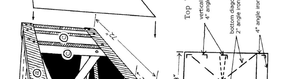
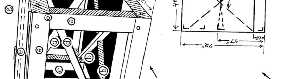
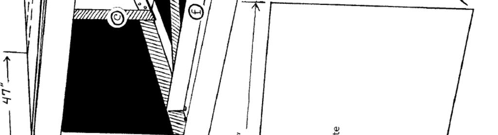
7 THE FRAME The overall external dimensions of the main frame (Fig. 7) are 72 by 48 and 28 ½ high. Special note should be taken as to how the angle iron will overlap in the corners to that these exterior dimensions are obtained. The angle iron used is 4 by 4 by 3/8. It is essential that the frame be precisely square, so that all the gears mounted in the frame are parallel. This can be accomplished in each rectangle by making sure that both diagonals measure exactly the same. The diagonal supports on the bottom of the frame use angle iron which is 2 by 2 by 3/8 (7b). There must be two vertical supports (7c) of 4 by 4 by 3/8 angle iron mounted on each side at a distance of 47 from the front. Again, diagonal supports (7d) are used at this same point made from 2 angle iron, also positioned 47 (outside dimension) from the front. Another 4 angle iron (7e) is mounted across the top of the frame also 47 form the front. One other 4 angle iron brace is mounted on the bottom of the frame, 12 (OD) back from the front (7f). Fig. 7 (opposite) The frame. Take special care to allow for angle iron overlap in corners: final exterior dimensions must be exactly 72" x 48" x 28 ½" high. It is essential that the frame be precisely square, so that mounted gears will be parallel. Check by measuring the diagonals. a. Main frame (72" x 48" x 28 ½") using (four of each length) 4" angle iron. b. Bottom diagonal supports using 2" angle iron. c. Vertical supports 28 1/2" using 4" angle iron. d. Vertical cross braces using 2" angle iron. e. Top brace 47" from frame front, and 47 1/4" long, using 4" angle iron. f. Bottom brace 47 ½" using 4" angle iron, 12" from front. g. g. Two ½" bolts are used to fasten each overlap of angle iron. At each overlap of the angle iron, two ½ bolts are used to fasten it securely. We found that the easiest way to build the frame was to tack-weld it together first. After tack-welding the frame together, three 3/8 metal plates for the frame must be constructed. These pieces should be cut out and tack-welded lightly to the frame. We made a portable drill press that could be clamped onto the frame at any point to drill the ½ holes. After drilling the holes through all the plates and angle iron junctions, remove the plates so that the inner workings can be installed. The differential can now be secured to the frame in exactly the spot shown in the diagrams (Fig. 8). Each corner of the differential s bottom plate is secured with a 3/4 bolt going into the frame s 4 angle iron.
8 Fig. 8 Differential installed at front of frame. Each corner of differential's bottom plate is secured with 3/4 bolt into frame. CHOOSING THE SPROCKETS The master sprocket (Fig. 9) we used is from a large, 8 cubic yard capacity cement mixer. This is located on the front side of the mixer cylinder, and is turned by a #160 chain. To remove it, it can be torched off the cylinder body a few inches around the circumference of the sprocket. The large bearing on which it turns must also be acquired. It is very important that this bearing be in good shape. We also got some of the other sprockets required from this type of cement mixer.
.")
9 Fig. 9 Master sprocket. Ours is from a large, 8 cubic yard capacity cement mixer. Torch off cylinder a few inches around sprocket. The large bearing on which it turns must also be acquired. Our sprocket was 54", approximately 85 teeth, turned by a #160 chain. A total of six sprockets are needed to drive the differential (Fig. 10). The top three sprockets: drive, driven, and idler sprockets use a #160 chain, while the second three sprockets use a #140 chain. These sprockets must not be excessively worn, or they will shorten the life of the chains. The chains may also be used from these cement mixers. But they must be in good shape, not stressed out, or they will ruin the sprockets. Fig. 10 Detail of master sprocket, showing riser and riser plate. The diameters and ratios of your sprockets may vary slightly from ours. We would recommend a larger main sprocket than ours, 85 teeth would be agood size. But the crucial factor to remember is that the RPM of the final driven sprocket on top of the differential must be at least as great as ours. This will decrease the torque which is being applied to the differential and make its job a lot easier to perform. To arrive at the final RPM, we begin by calculating for each set of gears the ratio of the number of teeth on the drive sprocket to the number of teeth on the driven sprocket. Next, multiply the two gear combination ratios together. For example, in our case, the ratios are 4.11 and 3.46, which gives us a total speed of RPM for every RPM of the oxen
.")
10 walking a complete circle. We have found that our oxen will walk a complete circle 2 times per minute, which, when multiplied by the RPM gear rotation figure, gives us a final speed on the differential axle of approximately 28.5 rotations per minuet. MASTER SPROCKET The large master sprocket must be installed first (Fig. 9). The bearing housing which came with the sprocket should bolt into the far side of the angle iron which is on top of the frame, 47 from the front of the unit (Fig. 7e). We had to add a second angle iron to the frame on the other side of the bearing to give it full support. Your bearing housing may be different from ours; nevertheless, it should still have its center at 54 from the sprockets should be at least 4 ½ above the top plate. On top of this sprocket, the poles, which we call tongues, will be situated for the oxen to turn. To accomplish this, we took a piece of 3 channel iron and bent it into a circle, so that it would sit nicely on top of the master sprocket s metal shell. This is called a riser and serves the purpose of giving a platform on which to mount the tongues that is enough above the chain to prevent interference. On top of this riser, we bolted a 3/8 piece of metal and then bolted the riser into the sprocket s metal shell (Fig. 10). Now it is ready to attach the tongues, but this will be done at a later point. Fig. 12 Jack shaft is fixed into pillow block which is bolted to back side of bottom angle iron. Cut 4" hole in top plate directly above this to allow shaft to extend above plate. THE JACK SHAFT The jack shaft is the vertical shaft which is turned by the large master chain, which in turn drive the differential axle by using a #140 chain underneath (Fig. 11a). The diameter of this shaft is 3 7/16, and it should be 36 long. The bottom of the shaft is fixed into a pillow-block, which is bolted into the angle iron running along the bottom, parallel with the front, 12 back
11 (Fig. 12, 7f). A 4 hole is cut in the top plate at the appropriate point for this shaft to extend through. The exact positions where the two sprockets will be mounted on the jack shaft must be determined at this point, so that key-ways can be cut into it. The sprockets should have taper- lock hubs for a 3 7/16 shaft. Again, these are the best hubs to use because they have bolts that draw the hub down into the sprocket, making an incredibly tight fit around the key. The top key-way in the shaft for the driven #160 sprocket should be at the point where the sprocket will sit exactly parallel with the master sprocket (Fig. 11c). The bottom sprocket made for a #140 chain should have its key-way cut so that the sprocket fits directly parallel with the #140 sprocket on the differential axle (Fig. 11c). We found it was a lot cheaper to cut one key-way from the top of the jack shaft down to the bottom of where the #140 sprocket sits, and this did not weaken the shaft. After the key-ways are cut, and the shaft is sitting in its vertical position in the pillow block (Fig. 11c), you should mount the #140 sprocket. Make sure it is exactly in line with its mate on the differential and properly torqued to the manufacturer s specifications. Now the top place can be installed over the jack shaft and the axle coming from the differential and bolted down into the frame.
12 Fig. 12 Jack shaft is fixed into pillow block which is bolted to back side of bottom angle iron. Cut 4" hole in top plate directly above this to allow shaft to extend above plate. The shaft is now secured at the top by using a flange block. This should be another heavyduty flange block with roller bearings and comparable to the one we used, which was a Linkbelt FB22455H. The flange block bolts into the top plate of the frame after making sure that the shaft is precisely parallel to the top of the frame and perpendicular to the other sprockets. Above this flange block, the #160 sprocket is mounted so that it is in line with the large master sprocket which will turn it. Remember, the closer the sprocket is to the flange block, the stronger it will be, but leave 1/8 separation, at least.
13 Fig. 13 Idler sprocket keeps chain tight and insures that 1/3 of teeth are engaged on every sprocket. Note compression spring. IDLER SPROCKET Now that the four main sprockets are installed and ready to be used, it is time that the idler sprockets (Fig. 13) be installed. These sprockets will keep the chain tight and make sure that the chain engages one-third of the teeth on every sprocket this is minimum requirement for extended chain and sprocket life. It must be possible to move and adjust the idler sprockets for correct tension, as the chain will gradually stretch out. A great deal of tension is required to hold these chains tight. We designed a simple mechanism using very strong compression springs to pull the idler sprocket into the chain. However, another simple method of tension regulation would be to use a turn-buckle type unit. This would serve the same purpose. After adding the top plate and installing the idler gears, we added another flange block bearing on top of the differential axle and bolted it down to the top plate (Fig. 14). Fig. 14 Heavy-duty flange block with roller bearings mounted over jack shaft and bolted into frame. This step will sandwich the driven sprocket on the differential axle between two flange blocks and increase the life-span of the differential, which is most important. Finally, the side
. Fig. 15 Mounted front plate.")

14 and front plates should be mounted after cutting out any sections for sprockets of the differential protruding from the frame (Fig. 15). Fig. 15 Mounted front plate. Before mounting, cut away sections to allow differential and sprockets to protrude, where necessary. Fig. 16 Universal joint of tumbling shaft. Corresponding yokes of all three joints are lined up so they turn together.
15 TUMBLING SHAFT Now is the time to get the drive shaft and universal joints form the truck. The drive shaft coming from the differential should be 4 ½ long. You may have to change yours, but it s easy. It connects at the end with a universal joint (Fig.16). The other end also has a universal joint. On the other side of this universal joint, the tumbling shaft is connected by splined (Fig. 17). The shaft is 2 3/16 in diameter and 8 long. The outer end of this shaft must also be splined, so that it connects into the third universal joint. These U-joints must be timed just right, which means that the corresponding yokes of all three joints are lined up so they turn together. We also used a homemade wooden support for the shaft just on the far side of the U-joint. This keeps the shaft as low to the ground as possible. Fig. 17 Tumbling shaft. The tumbling shaft is now spinning at around 200 RPM s and is outside the circle of oxen. Here is geared up again 3 ½ times to get a final shaft speed of about 700 RPM s. This final shaft has a large, hand-operated clutch to engage or disengage the final power take-off. The first priority for making this section of the power unit is to locate one of these clutches and also the main sprockets that you will use. The frame can be designed around the main components. We can describe our measurements and components and also share some experience.

16 Fig. 18 High-torque drive unit. T.B. Wood's HTD unit, shown here, uses serrated belt drive instead of chain. HIGH TORQUE DRIVE Instead of using chain-driven sprockets here, we used a serrated belt drive. The belt set- up has high mechanical efficiency, high resistance to wear, never needs lubrication, and runs very quietly. It needs no extra sprocket to keep it tight, as long as the center distances between the shafts is accurate. We selected T.B. Wood s High Torque Drive unit (Fig. 18). To gear it up 3 ½ times, we used a bottom sprocket, having 112 teeth, and a top support having 32 teeth. The belt is 55 mm wide and 2,100 mm long. It requires a center distance of between the shafts.

17 Fig. 19 HTD drive sprocket. Bottom shaft is splined and extends outside the frame to hook into the tumbling shaft. SHAFTS We mounted these sprockets on 2 3/16 diameter shafts. This size was convenient for us, but the bottom shaft could be as small as 1 15/16 and the top one as small as 1 3/4 in diameter. The bottom shaft is held by two pillow blocks, with one end splined and extending outside the frame to hook into the tumbling shaft (Fig. 19). The top shaft also mounts through two pillow blocks, with its far ending connecting into the fly wheel of the hand clutch. The shaft will need key-ways to hold the sprockets. The larger bottom sprocket will extend below ground level, and a protective guard should be built around it. Then the ground can be dug out, so the whole frame sits flat on the ground, with the sprocket protected below the surface. THE CLUTCH There are many companies which make large clutches that are operated by a hand lever. Used ones are found on a variety of power units, such as sawmills, generators or cranes. As long as the shaft coming off the clutch is at least 1 3/4 in diameter, it should withstand the load without slipping. This clutch should have a flywheel on the inside to which the top shaft on the frame can be bolted (Figs. 20,21). If you consider a used clutch, it is important to check the clutch pads and know if new pads are available. There may be only one bearing on the outer shaft and a pilot bushing on the inside. These must be in good working condition. Finally, the shaft coming out of the clutch must be keyed so that the pulleys can be fitted on without any problems.


18 Fig. 20 Flywheel and clutch attached to HTD unit. Fig. 21 HTD unit flywheel clutch. If you consider a used clutch, check clutch pads and find out whether new replacement pads are available.
. They are place underneath the sprocket, just inside where the chain rides on the teeth.")
19 Fig. 22 Master sprocket stabilizing rollers keep master sprocket level as it rotates. Outside edge or roller must be hardened to prevent mushrooming of metal. STABILIZING ROLLERS These rollers are used to keep the large master sprocket level as it rotates (Fig. 22). They are place underneath the sprocket, just inside where the chain rides on the teeth. Six rollers are used in all. Three of them go side-by side, underneath the sprocket closest to where the driven sprocket is located. The other three get spaced evenly around the sprocket (Fig. 23). The rollers are made of 1 wide steel that is cut from 5 diameter stock. A 1 7/16 hole is bored in the center so that an axle is held at both ends by pillow blocks (Fig. 22). After the exact position of the roller on the axle is determined, they should be welded together. The outside edge of the roller must now be hardened to prevent mushrooming of the metal, which is otherwise most certain to occur.
20 Fig. 23 Placement of stabilizing rollers beneath master sprocket. Fig. 24 Five tongues turn the master sprocket. Angle iron is attached to both sides of tongue.
21 Fig. 25 Overhead view of tongue arrangement, showing chain braces. TONGUES There are five tongues that turn the master sprocket. The tongues are 4 by 4 wood, 13 6 long (Fig. 24). They are held by 4 angle iron that bolts into the riser plate. Angle iron is on both sides of the tongue and is 4 long. Both pieces are connected at the top and bottom for strength. To relieve most of the tension from the wood, a chain brace is used on each tongue (Fig. 25). The chain runs from the end of each tongue back to the metal angle iron on the tongue behind. A turnbuckle is used on each chain for easy adjustment (Fig. 26).
22 Fig. 26 Detail of Fig. 25, chain brace between tongues, showing turnbuckle for tension adjustment. EVENERS An evener is set-up is necessary to limit the fluctuation in pull, which would cause the unit to turn in irregular RPM s. A 5 pulley is mounted at the end of each tongue by using two pieces of 4 by 6 angle iron (Fig. 27). Fig. 27 Detail of evener set-up at end of tongue. A cable goes from the pulling ox or oxen back around the outside of the pulley and then 270 degrees around the pulley. The cable continues on to another smaller 3 pulley attached at the end (Fig. 28).
23 Fig. 28 Detail of evener set-up showing smaller pulley. Fig. 29 Evener set-up showing complete pulley arrangement.
24 Total cable length is 5, with even amounts on either side of the large pulley (Fig. 29). To connect all this together, a large cable passes through each of the five smaller pulleys and connects back to itself to form a complete circle (Fig. 30). Thus, as the oxen are pulling on their individual small cables, the pull is transferred to the large cable, and it is immediately taken up by the others. We underestimated the importance of these eveners at first. However, after a few weeks of running our power unit, we noticed that the oxen had to walk a little to far forward to get a good pull. So we shortened the larger cable by about 18 around. Thus, each of the smaller cables got pulled by a little. The result was astounding: our oxen were able to pull much more easily and much harder with half the attention by the driver. After this, one driver was more than able to handle the whole unit single-handedly. Fig. 30 Comprehensive view of pulley arrangement, showing placement in relation to master sprocket tongues and oxen. Dr. Gurmit Singh
 DRUM BRAKE RIMS Periodic inspection of drum brake rims is necessary to determine indications of uneven or excessive wear. In general, brake rim failures other that regular wear are caused by brake linings
MANUAL TRANSMISSION SERVICE
 MANUAL TRANSMISSION SERVICE Introduction Internal combustion engines develop very little torque or power at low rpm. This is especially obvious when you try to start out in direct drive, 4th gear in a
Maintenance Instructions
 General Note These instructions contain information common to more than one model of Bevel Gear Drive. To simplify reading, similar models have been grouped as follows: GROUP 1 Models 11, 0, 1,, (illustrated),,
DRIVE AXLE Nissan 240SX DESCRIPTION & OPERATION AXLE RATIO & IDENTIFICATION AXLE SHAFT & BEARING R & I DRIVE SHAFT R & I
 DRIVE AXLE 1990 Nissan 240SX 1990 DRIVE AXLES Rear Axle - R200 240SX, 300ZX DESCRIPTION & OPERATION The axle assembly is a hypoid type gear with integral carrier housing. The pinion bearing preload adjustment
Transmission Overhaul Procedures-Bench Service
 How to Assemble the Lower Reverse Idler Gear Assembly Special Instructions In 1996 Eaton changed the reverse idler system design. In the nut design, the reverse idler bearing was lubricated through a hole
The Ryan Overdrive by Tom Endy
 The Ryan Overdrive by Tom Endy The Ryan overdrive is a factory built overdrive designed for the Model a Ford. They were manufactured in Denver, Colorado and marketed between 1990 and 2000. They were discontinued
Installation Instructions
 Preparing your vehicle to install your brake system upgrade 1. Rack the vehicle. 2. If you don t have a rack, then you must take extra safety precautions. 3. Choose a firmly packed and level ground to
INSTALLATION INSTRUCTIONS
 INSTALLATION INSTRUCTIONS R1 REAR DRUM TO DISC BRAKE CONVERSION KIT A130-3 JEEP CJ SERIES W/AMC-20 REAR AXLES AND 5 x 5-1/2" BOLT CIRCLE Thank you for choosing STAINLESS STEEL BRAKES CORPORATION for your
CALIFORNIA TRIMMER MOWER MAINTENANCE MANUAL
 CALIFORNIA TRIMMER MOWER MAINTENANCE MANUAL 2 Table of Contents Section 1: General Information Page Handle Assembly Instructions 4 Maintenance All Models 6 Oil Change Procedures All Models 9 Height Adjustment
INSTALLATION, MAINTENANCE, & SAFETY INSTRUCTIONS
 Tarpaulin Systems Flip -N- Go / Quick Mount Flip -N- Go System INSTALLATION, MAINTENANCE, & SAFETY INSTRUCTIONS (800) CRAMARO (800) 272-6276 Plants In: Delaware, Florida, Massachusetts, Nevada, Ohio Install
Driver Driven. InputSpeed. Gears
 Gears Gears are toothed wheels designed to transmit rotary motion and power from one part of a mechanism to another. They are fitted to shafts with special devices called keys (or splines) that ensure
WARNING: the engine does not come with oil in it. Please fill the oil before starting. The 200cc hardknock requires 9/10 of a quart of oil.
 WARNING: the engine does not come with oil in it. Please fill the oil before starting. The 200cc hardknock requires 9/10 of a quart of oil. Things needed for assembly. -2 tubes of blue loc-tite. I don
WOOD CHIPPER WC1103 5PQ (8/02/12)
") O P E R A T O R ' S M A N U A L WOOD CHIPPER WC1103 5PQ990101 (8/02/12) To the Owner; Thank-You for choosing a quality product from Frontier Equipment. We strive to give you the best equipment and the
O P E R A T O R ' S M A N U A L WOOD CHIPPER WC1103 5PQ990101 (8/02/12) To the Owner; Thank-You for choosing a quality product from Frontier Equipment. We strive to give you the best equipment and the
Chrysler A-Body Tubular A-Arms Installation Instructions A-ARM INSTALLATION
 1967-1976 Dodge Demon 1112 67-72 Chrysler A-Body Tubular A-Arms Installation Instructions Thank you for your purchase of this Hotchkis Performance product. Your A-Arm set was designed with the performance
CHAPTER 7 FRONT AXLE
 CHAPTER 7 FRONT AXLE 1. STRUCTURE FRONT AXLE 1.1 FRONT AXLE STRUCTURE 704W701A (1) Front Bracket (2) Rear Bracket (3) Center Pin (4) Front Axle Support (5) Bevel Gear Case (6) Front Axle Case (7) Front
Installation Instructions Table of Contents
 Installation Instructions Table of Contents Pre- Installation of Garage Storage Lift 2 Layout the Garage Storage Lift 3 Installing the strut Channels 3 Install the Drive Assembly 5 Install the Drive Shaft
1204AA Ford Mustang Double Adjustable Trailing Arms
 1204AA 79-04 Ford Mustang Double Adjustable Trailing Arms Special Tools Required for this Installation - 4 post lift or alignment rack preferable - Air Chisel, Angle Finder (Digital Preferred), Dead blow
'99-03 CHEVROLET/GMC IFS 4WD 6" SUSPENSION SYSTEM P/N INSTALLATION INSTRUCTIONS
 1/16/04 '99-03 CHEVROLET/GMC IFS 4WD 6" SUSPENSION SYSTEM P/N. 10-41099 INSTALLATION INSTRUCTIONS NOTE: Each Lift Kit and options to Lift Kits are packaged separately. Therefore, installation procedures
Safety - Installation and Operation:
 4x4 or 4x2 Instructions EZGO Electric Cars Thank you for purchasing your 4x4 or 4x2 conversion kit. Safety at all times whether during installation or operation is utmost importance. Before After!!!!!!!!!!!!!!
DRIVE AXLE Volvo 960 DESCRIPTION & OPERATION AXLE IDENTIFICATION DRIVE AXLES Volvo Differentials & Axle Shafts
 DRIVE AXLE 1994 Volvo 960 1994 DRIVE AXLES Volvo Differentials & Axle Shafts 960 DESCRIPTION & OPERATION All 960 station wagon models use type 1041 rear axle assembly. All 960 4-door models use type 1045
ADVANCE ADAPTERS INC. P/N: NP231 SHORT SHAFT "FIXED YOKE" KIT
 Paso Robles, CA 93447 PAGE 1 OF 10 Telephone: (800) 350-2223 Fax: (805) 238-4201 Page Rev. Date: 06-24-02 KIT CONSISTS OF: No. Qty Part No. Description 1. 1 51-7906 TAILHOUSING, DIECAST 2. 1 52-7905 SHAFT,
MECHANISMS. AUTHORS: Santiago Camblor y Pablo Rivas INDEX
 MECHANISMS AUTHORS: Santiago Camblor y Pablo Rivas INDEX 1 INTRODUCTION 2 LEVER 3 PULLEYS 4 BELT AND PULLEY SYSTEM 5 GEARS 6 GEARS WITH CHAIN 7 WORM GEAR 8 RACK AND PINION 9 SCREW AND NUT 10 CAM 11 ECCENTRIC
N. 15th Street, Middlesboro, KY TARP-N-GO SYSTEMS INSTALLATION INSTRUCTIONS
 1-800-248-7717 1002 N. 15th Street, Middlesboro, KY 40965 TARP-N-GO SYSTEMS INSTALLATION INSTRUCTIONS Congratulations on your purchase of a Mountain Tarp Tarp-N-Go tarping system. With tarping systems
Installation and Operation Manual. Manufacturers of Innovative Materials Handling Equipment since 1957.
 SWINGSET DISTRIBUTOR Installation and Operation Manual Manufacturers of Innovative Materials Handling Equipment since 1957. 491 North Emerson Street * Cambridge MN 55008-1316 U.S.A. Toll Free (800) 328-8002
Transmission Overhaul Procedures-Bench Service
 How to Install the Auxiliary Countershaft Assembly Special Instructions To make auxiliary section assembly easier, you can make an auxiliary section fixture out of a 2" x 12" piece of wood. 3' 1' 3" 4.56"
60-65 Falcon, Comet & Ranchero Coil Spring IFS
 60-65 Falcon, 62-65 Comet & 62-65 Ranchero Coil Spring IFS All engine installations with this front end will require a rear sump oil pan. 289-302 Small Block Ford Motors Milodon rear sump pan holds 7 quarts
Installation Instructions
 Suzuki Samurai 1 Inch and 2 Inch Body Lift Kit (SKU# SSP-BL) Installation Instructions Background: These instructions are designed for installing the 2 body lift. Our approach is to raise the entire body
Mustang 7.5 Limited Slip Differential (28 Spline) V8; V6:
 V8; V6:") Mustang 7.5 Limited Slip Differential (28 Spline) 79-85 V8; 86-10 V6: Required Tools: Ratchet Wrench Torque Wrench 1/2", 5/16, 3/4", 12mm and 15mm Sockets Lug nut Wrench Dial Indicator Digital Measuring
Mustang 7.5 Limited Slip Differential (28 Spline) 79-85 V8; 86-10 V6: Required Tools: Ratchet Wrench Torque Wrench 1/2", 5/16, 3/4", 12mm and 15mm Sockets Lug nut Wrench Dial Indicator Digital Measuring
GatesFacts Technical Information Library Gates Compass Power Transmission CD-ROM version 1.2 The Gates Rubber Company Denver, Colorado USA
 MAKING THE RIGHT SHAFT CONNECTIONS Daniel Schwartz & Gary Porter Power Transmission Design August, 1996 Securing a belt pulley to a drive shaft often seems like such a routine task, that engineers and
MM Heavy Duty Torque-arm (MMTA-3 & -4) Engine Torque Table 4.56: : :
 Engine Torque Table 4.56: : :") 3430 Sacramento Dr., Unit D San Luis Obispo, CA 93401 Telephone: 805/544-8748 Orders Only: 800/839-0928 Fax: 805/544-8645 The ultimate rear suspension for your Mustang is now available from Maximum Motorsports.
3430 Sacramento Dr., Unit D San Luis Obispo, CA 93401 Telephone: 805/544-8748 Orders Only: 800/839-0928 Fax: 805/544-8645 The ultimate rear suspension for your Mustang is now available from Maximum Motorsports.
HORSTMAN GREASED LIGHTNING CLUTCH
 HORSTMAN GREASED LIGHTNING CLUTCH Horstman s Greased Lightning (GL) clutch is designed for ultra high performance, and requires expert setup and a serious commitment to maintenance. Warning!!! 1. Clutch
ADVANCE ADAPTERS INC. Fixed Yoke kit (S.Y.E. Kit)
") ADVANCE ADAPTERS INC. Fixed Yoke kit (S.Y.E. Kit) Instruction Sheet P/N: 50-7905 & 50-7906 KIT CONSISTS OF: No. Qty Part No. Description 1. 1 51-7906 TAILHOUSING, DIECAST 2. 1 52-7905 SHAFT, MAIN OUTPUT
ADVANCE ADAPTERS INC. Fixed Yoke kit (S.Y.E. Kit) Instruction Sheet P/N: 50-7905 & 50-7906 KIT CONSISTS OF: No. Qty Part No. Description 1. 1 51-7906 TAILHOUSING, DIECAST 2. 1 52-7905 SHAFT, MAIN OUTPUT
MANUAL TRANSMISSION MUA 5C (4X2, 4X4) AND TREMEC T5R(4X2)
 AND TREMEC T5R(4X2)") MANUAL TRANSMISSION 7B 1 RODEO TRANSMISSION MANUAL TRANSMISSION MUA 5C (4X2, 4X4) AND TREMEC T5R(4X2) CONTENTS Service Precaution...................... 7B 2 General Description..................... 7B
MANUAL TRANSMISSION 7B 1 RODEO TRANSMISSION MANUAL TRANSMISSION MUA 5C (4X2, 4X4) AND TREMEC T5R(4X2) CONTENTS Service Precaution...................... 7B 2 General Description..................... 7B
Instructions to install the early ( ) Limited Slip Differential in the Late-model ( ) G28 Transaxle
 Limited Slip Differential in the Late-model ( ) G28 Transaxle") Instructions to install the early (1978-83) Limited Slip Differential in the Late-model (1985-1995) G28 Transaxle BACKGROUND: Most 928 owners know about the improvements to the 5- speed transaxle that
Instructions to install the early (1978-83) Limited Slip Differential in the Late-model (1985-1995) G28 Transaxle BACKGROUND: Most 928 owners know about the improvements to the 5- speed transaxle that
By AM Customer: Dean Smith, Aug. 8, 2014.
 Ford Racing Bullitt Axle-Back Exhaust (05-09 GT, GT500) By AM Customer: Dean Smith, Aug. 8, 2014. Tools for the Job: 13mm Wrench 13mm Socket 15mm Socket 15mm Deep Socket Ratchet(s) [I used a bigger one
Suzuki Samurai to Toyota Front Spring Swap Kit, with Missing Link Shackles (SKU#SSP-TSFM) Installation Instructions
 Installation Instructions") Suzuki Samurai to Toyota Front Spring Swap Kit, with Missing Link Shackles (SKU#SSP-TSFM) Installation Instructions CAUTION: Safety glasses should be worn at all times when working with vehicles and related
Suzuki Samurai to Toyota Front Spring Swap Kit, with Missing Link Shackles (SKU#SSP-TSFM) Installation Instructions CAUTION: Safety glasses should be worn at all times when working with vehicles and related
Model 320 / 320A Hinge Assembly
 MANUFACTURING CO. THE FIRST NAME IN QUALITY COUPLINGS Installation, Inspection, Operation & Maintenance Guide Model 320 / 320A Hinge Assembly IMPORTANT Read these instructions completely before installing,
Build an electric Scoot-car
 513 Build an electric Scoot-car Designed by ROBERT W O O L S O N Here's a sidewalk special for young hot rodders that safely takes the corner on two wheels, has two forward speed and brakes that stop on
1988 Chevrolet Pickup V SUSPENSION - FRONT (4WD)' 'Front Suspension - "V" Series 1988 SUSPENSION - FRONT (4WD) Front Suspension - "V" Series
' 'Front Suspension - V Series 1988 SUSPENSION - FRONT (4WD) Front Suspension - V Series") 1988 SUSPENSION - FRONT (4WD) Front Suspension - "V" Series DESCRIPTION NOTE: Vehicle serial numbers used in this article has been abbreviated for common reference to Chevrolet and GMC models. Chevrolet
1988 SUSPENSION - FRONT (4WD) Front Suspension - "V" Series DESCRIPTION NOTE: Vehicle serial numbers used in this article has been abbreviated for common reference to Chevrolet and GMC models. Chevrolet
WOOD CHIPPER WC1105 5PQ (8/08/2012)
") O P E R A T O R ' S M A N U A L WOOD CHIPPER WC1105 5PQ990102 (8/08/2012) To the Owner; Thank-You for choosing a quality product from Frontier Equipment. We strive to give you the best equipment and the
O P E R A T O R ' S M A N U A L WOOD CHIPPER WC1105 5PQ990102 (8/08/2012) To the Owner; Thank-You for choosing a quality product from Frontier Equipment. We strive to give you the best equipment and the
OVERLOAD CLUTCHES FOR INDEX DRIVES
 The Driving Force in Automation OVERLOAD CLUTCHES FOR INDEX DRIVES WARNING WARNING This is a controlled document. It is your responsibility to deliver this information to the end user of the CAMCO indexer.
PYRTE. Building The Front Axle, Fork and Steering
 PYRTE Building The Front Axle, Fork and Steering The front axle on this traction engine is a very simple affair, in that it is a rectangular steel rod, sat on edge, with a pivot in the centre, which is
NP231 SHORT SHAFT "FIXED YOKE" KIT
 Page 1 of 11 KIT CONSISTS OF: No. Qty Part No. Description 1. 1 51-7905 TAILHOUSING, DIECAST 2. 1 52-7905 SHAFT, MAIN OUTPUT 3. 1 300474 SEAL WASHER, REAR YOKE 4 1 300475 YOKE, C.V. REAR 5. 1 300476 NUT,
'88-'00 CHEVROLET/GMC IFS 4WD(8LUG) OLD BODY STYLE 6" SUSPENSION SYSTEM P/N
 OLD BODY STYLE 6 SUSPENSION SYSTEM P/N") 4/10/13 '88-'00 CHEVROLET/GMC IFS 4WD(8LUG) OLD BODY STYLE 6" SUSPENSION SYSTEM P/N. 10-41888 INSTALLATION INSTRUCTIONS APPLICATION WARNING: Applicable for hub mounted ABS sensor models only. Not for 1992-94
4/10/13 '88-'00 CHEVROLET/GMC IFS 4WD(8LUG) OLD BODY STYLE 6" SUSPENSION SYSTEM P/N. 10-41888 INSTALLATION INSTRUCTIONS APPLICATION WARNING: Applicable for hub mounted ABS sensor models only. Not for 1992-94
INSTRUCTION G-Comp Unser Edition Rear Suspension: Chevy Nova. Kit Contents:
 INSTRUCTION 350-400 G-Comp Unser Edition Rear Suspension: 62-67 Chevy Nova Speedway Motors, Inc. 2017 Kit Contents: 350003.1 G-Comp Chassis Brace 350003.2 G-Comp Front Support 350400.1 Chevy II Unser Rear
ROLLER CHAIN SPROCKETS INDEX...E-1 E-2 MADE-TO-ORDER CAPABILITIES...E-3
 Index SECTION E ROLLER CHAIN SPROCKETS PRODUCT PAGE INDEX...E-1 E-2 MADE-TO-ORDER CAPABILITIES...E-3 SECTION I STANDARD SPROCKETS...E-4 E-112 Shear Pin Sprockets, Bolt-On...E-4 E-6 Type D Sprockets, Detachable
Tech Note Truck 14 & 15.5 Twin Plate Cast Iron Type Installation Guidelines
 1. (14 & 15.5 ) Check condition of the flywheel. Grind to resurface or replace flywheel. Surface MUST BE machined or premature clutch failure can occur. Flywheel depth must be 2.938 (74.62mm) for 14 (350mm)
OPERATION AND PARTS MANUAL
 OPERATION AND PARTS MANUAL MODEL NUMBER : PART NUMBER : GRL 1110 1900-0540 SERIAL NUMBER : BAYNE MACHINE WORKS, INC. PHONE: 864.288.3877 910 FORK SHOALS ROAD TOLL FREE: 800.535.2671 GREENVILLE SC, 29605
1203AA GM A-BODY Double Adjustable Trailing Arms
 1203AA 64-67 GM A-BODY Double Adjustable Trailing Arms Warning: This installation should be performed by a trained professional. Note, pictures in this booklet are from a 77-96 GM B Body. Installation
MM Rear Coil-Over Kit - Bilstein Shocks (MMCO-3)
") 3430 Sacramento Dr., Unit D San Luis Obispo, CA 93401 Telephone: 805/544-8748 Fax: 805/544-8645 www.maximummotorsports.com MM Rear Coil-Over Kit - Bilstein Shocks (MMCO-3) Read all instructions before
3430 Sacramento Dr., Unit D San Luis Obispo, CA 93401 Telephone: 805/544-8748 Fax: 805/544-8645 www.maximummotorsports.com MM Rear Coil-Over Kit - Bilstein Shocks (MMCO-3) Read all instructions before
MP140 - SERVICE Dodge Nitro R/T TRANSFER CASE MP140 - Service Information - Nitro DESCRIPTION
 1 - INPUT SEAL 15 - WEAR SLEEVE 2 - VENT 16 - FLANGE 3 - FRONT CASE 17 - FLANGE SEAL 4 - INPUT GEAR 18 - FLANGE NUT 5 - PILOT BEARING 19 - ID. TAG 6 - PLANETARY GEAR 20 - DRAIN/FILL PLUGS 7 - SPROCKET
Valtek Auxiliary Handwheels and Limit Stops
 Valtek Auxiliary s and Limit Stops Table of Contents Page 1 General information 2 Installation 2 Side-mounted handwheels, size 25 and 50 (linear actuators) 3 Side-mounted handwheels, size 100 and 200 (linear
How To Build A Mini Chopper!
 How To Build A Mini Chopper! by Custom-Choppers-Guide.com Copyright All Rights Reserved. If you are new to such projects, it is strongly recommended that you do an assembly job, purchasing pre-constructed
TABLE OF CONTENTS 0 FRONT DRIVE , WHEEL HUB , WHEEL HUB BEARING , KNUCKLE
 Subsection 01 (TABLE OF CONTENTS) TABLE OF CONTENTS 0 FRONT DRIVE... 06-02-1 1, WHEEL HUB... 06-02-2 2, WHEEL HUB BEARING... 06-02-2, KNUCKLE... 06-02- FINAL DRIVE... 06-0-1 1, DRIVE CHAIN... 06-0-2 2,
LOWE Industries. Fuel Pump Cam Drive BBC JESEL Standard Cam Location. Complete Kit Fits JESEL KBD Other items you may need..
 LOWE Industries PO Box 180 Rosewood, Qld 4340 Australia www.kenlowe.com.au Phone 0411-699 535 Fuel Pump Cam Drive BBC JESEL Standard Cam Location Complete Kit Fits JESEL KBD32000 Fuel pump mounting holes
De clunking your MGB rear axle. By Stuart Clarke
 De clunking your MGB rear axle By Stuart Clarke Do you have that annoying clunking noise when accelerating or decelerating, or even when you lift off to change gear, well it s possible to resolve the issue
Installation instructions
 Installation instructions warning: never exceed your vehicle manufacturer's recommended towing capacity BOLT-TOGETHER WEIGHT DISTRIBUTION MAINTENANCE Keep the socket-mounted ends of the spring bars and
Installation Instructions
 DODGE 20K Industry Standard Rail Custom Mounting Kit #2742 Gross Trailer Weight (Maximum)...20,000 lbs. Vertical Load Weight (Max. Pin Weight)...5,000 lbs. SYSTEM TOW CAPACITY Please note, in order to
Peg-Harness installation instructions
 Peg-Harness installation instructions I know it s not the easiest thing to do, but PLEASE READ THESE INSTRUCTIONS COMPLETELY so you will understand what you are trying to accomplish before you start drilling
TC20 Chain Driven Power Take-Off Overhaul Instructions
 TC20 Chain Driven Power Take-Off Overhaul Instructions Table of Contents Section Page Introduction 4 Ordering Repair Parts 4 General Information 5 Special Tools 6 Disassembly See Page 2 Reassembly See
J&M Mustang Adjustable Panhard Rod (05-09) - Installation Instructions
 - Installation Instructions") J&M Mustang Adjustable Panhard Rod (05-09) - Installation Instructions The below installation instructions work for the following products: J&M Mustang Adjustable Panhard Rod (05-09) Please read through
J&M Mustang Adjustable Panhard Rod (05-09) - Installation Instructions The below installation instructions work for the following products: J&M Mustang Adjustable Panhard Rod (05-09) Please read through
 Page 1 of 15 Transmission, Model S5-42 ZF Model S5-42 ZF Disassembly NOTE: For 4x4 and F-Super Duty vehicles, skip to Step 5. 1. Attach the transmission to the Bench Mounted Holding Fixture T57L-500-B
EC789 Converting Horse Drawn Mowers into Power Mowers
 University of Nebraska - Lincoln DigitalCommons@University of Nebraska - Lincoln Historical Materials from University of Nebraska- Lincoln Extension Extension 5-1945 EC789 Converting Horse Drawn Mowers
PROPELLER SHAFTS 16-1 PROPELLER SHAFTS CONTENTS
 Z PROPELLER SHAFTS 16-1 PROPELLER SHAFTS CONTENTS page GENERAL INFORMATION... 1 PROPELLER SHAFT REPLACEMENT... 7 SERVICE DIAGNOSIS/PROCEDURES... 3 page TORQUE SPECIFICATIONS... 14 UNIVERSAL JOINT REPLACEMENT...
BALE HANDLING SYSTEMS
 HAYRITE BALE HANDLING SYSTEMS Stronger Construction Better Engineering Smoother, More Dependable Operation Wider Choice of Accessories HA YR IT E Lower Cost Got A Question? Our skilled staff has the proven
Power Heads. Standard Unload. Power Sweep. Commercial Unload. Bin Systems. Unloading
 Standard Unload Power Sweep Commercial Unload Power Heads Unloading Bin Systems Klean Sweep the finishing touch. The unique back-up shield and torque tube combination adjusts for close floor clearance
INSTALLATION INSTRUCTIONS R1 REAR CONVERSION KIT
 INSTALLATION INSTRUCTIONS R1 REAR CONVERSION KIT INSTRUCTION FOR ASSEMBLY OF JEEP CJ SERIES W/AMC 20 REAR AXLES, 5 x 5-1/2" BOLT CIRCLE WITH A130-4 FULL FLOATING AXLE OR A130-5 (1 PIECE AXLE) Thank you
This document goes through the basic steps required to utilize the electric window motors from the Ford Mk3 Mondeo.
 Modifying Ford Mk3 Mondeo door glass motors The options for installing electric windows in a Diablo replica are limited to only a few options; You can install the original motor and cable runners at 500
$1.00 FOR THE TQIO/RCIO
 $1.00 FOR THE TQIO/RCIO m mm HDBBYSHOP Champion Jay Halsey has an impressive track record. One of Jay's advantages is a whisper smooth tranny thanks to his dad, Jim. Now you can build a Halsey transmission!
Clutch Kit Install Guide
 Jack up and support the car on jack stands Remove the exhaust system (some models) Remove the driveshaft (rear wheel drive) Remove CV axle (front wheel drive) Manual transmission removal Clutch Kit Install
Hytrol's ABC Conveyor Book
 Hytrol's ABC Conveyor Book WHAT IS A CONVEYOR? A conveyor moves material. A conveyor moves cardboard boxes, wood boxes, metal boxes and plastic boxes. A conveyor can move material This is called a GRAVITY
Clutch Installation Guide
 Clutch Installation Guide 0 STOP! READ CAREFULLY BEFORE INSTALLING CLUTCH This clutch must be installed by a qualified installer. Improper installation or failure to replace or resurface the flywheel,
Assortment 2013_FPT BOOK.indb /02/13 6:57 PM
 Assortment Contents Why compete against your supplier when you can be our partner Chain Tensioners...14 see Chains section for details Anti-Vibration Mounts...224 Key Steel...225 Motor Rails...226 Self
2006 MINI Cooper S GENINFO Starting - Overview - MINI
 MINI STARTING SYSTEM * PLEASE READ THIS FIRST * 2002-07 GENINFO Starting - Overview - MINI For information on starter removal and installation, see the following articles. For Cooper, see STARTER WITH
Timing the 9N/2N Steering Sector Gears
 Timing the 9N/2N Steering Sector Gears by John Korschot - www.johnsoldiron.com (May 2010) The procedure for timing a set of steering gears in the 9/2n tractors is published in the I&T FO4 shop manual.
WJ 6.5" Long Travel PART #: RK-605LT-WJ APPLICATION: WJ
 Rusty s Off-Road Products 7161 Steele Station Road Rainbow City, AL 35906 Phone: (256) 442-0607 FAX: (256) 442-0017 Web Site: www.rustysoffroad.com WJ 6.5" Long Travel PART #: RK-605LT-WJ APPLICATION:
LOR Series Trig-O-Matic Lite Overload Release Clutch
 LOR Series Trig-O-Matic Lite Overload Release Clutch P-3029-BG LOR Series Installation and Operation An Altra Industrial Motion Company Contents I. Introduction A. Operating Principle... 3 B. Torque Adjustment...
MANUAL TRANSMISSIONS Mitsubishi F4M20, F5M20, F5M30 & KM200 Series TRANSMISSION APPLICATION
 Article Text ARTICLE BEGINNING MANUAL TRANSMISSIONS Mitsubishi F4M20, F5M20, F5M30 & KM200 Series APPLICATION TRANSMISSION APPLICATION Vehicle Application Transmission Model Chrysler Motors (2WD) 4-Speed
Self-Adjust Clutch Installation Guide
 Self-Adjust Clutch Installation Guide 0 STOP! READ CAREFULLY BEFORE INSTALLING CLUTCH This clutch must be installed by a qualified installer. Improper installation or failure to replace or resurface the
OPERATION AND PARTS MANUAL
 OPERATION AND PARTS MANUAL MODEL NUMBER : PART NUMBER : GTL 1110 1900-0510 SERIAL NUMBER : BAYNE MACHINE WORKS, INC. PHONE: (864) 288-3877 910 FORK SHOALS ROAD TOLL FREE: (800) 535-2671 GREENVILLE S.C.,
WH Ford 2WD Steering System #2013/2015 Date 02/15/04 rev. 1
 Phone (209) 400-7200 Fax (209) 943-7923 www.wildhorses4x4.com WH Ford 2WD Steering System #2013/2015 Date 02/15/04 rev. 1 Basic system notes: This system works on 1966-1977 Broncos with manual steering
TRANSMISSION 6.7 GENERAL HOME. See Figure The transmission is a five-speed constantmesh type housed in an extension of the crankcase.
 TRANSMISSION 6.7 GENERAL See Figure 6-45. The transmission is a five-speed constantmesh type housed in an extension of the crankcase. Mainshaft Neutral Mainshaft st Gear b06x6x Countershaft 4 Out 5 Countershaft
Boston Gear LOR Series
 Boston Gear LOR Series Trig-O-Matic Lite Overload Release Clutch Installation and Maintenance Instructions Doc. No. LOR Series Trig-O-Matic Lite www.bostongear.com LOR SERIES TRIG-O-MATIC LITE OVERLOAD
Porsche 928 with 16v LH-Jetronic Fuel System
 Porsche 928 with 16v LH-Jetronic Fuel System Toll-Free Tech Hot Line: 877-FOR-928M 877-367-9286 Please do not copy this manual and give copies to your friends. Our ability to bring you this supercharger
This file is available for free download at
 This file is available for free download at http://www.iluvmyrx7.com This file is fully text-searchable select Edit and Find and type in what you re looking for. This file is intended more for online viewing
BRAKE SYSTEM Nissan 240SX DESCRIPTION BRAKE BLEEDING * PLEASE READ FIRST * BLEEDING PROCEDURES ADJUSTMENTS BRAKE PEDAL HEIGHT SPECS TABLE
 BRAKE SYSTEM 1990 Nissan 240SX 1990 BRAKE SYSTEMS Nissan Disc & Drum Axxess, Maxima, Pathfinder, Pickup, Pulsar NX, Sentra, Stanza, 240SX, 300ZX DESCRIPTION All brake systems are hydraulically operated
FOR MORE INFORMATION CALL CLARK ROLLER CHAIN SPROCKETS INDEX...E-1 - E-2 MADE-TO-ORDER CAPABILITIES...
 Index SECTION E ROLLER CHAIN PRODUCT PAGE INDEX...E- - E-2 MADE-TO-ORDER CAPABILITIES...E- SECTION I STANDARD...E-4 - E-2 Shear Pin Sprockets, Bolt-On...E-4 - E-6 Type D Sprockets, Detachable s Split and
INSTALLATION MANUAL. TORQ Locker TL GM 14 Bolt Installation Instructions. Made in USA By: Page 1 of 8
 INSTALLATION MANUAL TORQ Locker TL-19035 GM 14 Bolt Installation Instructions Made in USA By: Page 1 of 8 Page 2 of 8 INSTALLATION MANUAL TORQ Locker TL-19035 GM 14 Bolt Installation Instructions By: INTRODUCTION
Interlocks 325 Series
 rd 12070 43 St. NE, St. Michael, MN 55376 763-497-7000 www.tcamerican.com sales@tcamerican.com Installation Instructions Interlocks 325 Series 3I-615; 3I-430 3I-613; 3I-450 Crane Interlock and Operating
Wallace Tri-Adjustable Gantry Cranes Square Tube Assembly Instructions
 Wallace Tri-Adjustable Gantry Cranes Square Tube Assembly Instructions For any additional information, Please call 1- S 1. Read and understand instructions before using this gantry. 2. Inspect gantry thoroughly
Make sure all tubes are installed to your satisfaction BEFORE finish welding!!
 INTRODUCTION: This S&W Roll Bar or Roll Cage performs both a safety and performance function. As a safety device, the main hoop of the cage protects the driver from impact. The rear braces and side bars
INSTALLATION INSTRUCTIONS
 INSTALLATION INSTRUCTIONS FX4 ELITE REAR DISC CONVERSION KITS WITH INTERNAL PARKING BRAKE A110-14, A111-25, A111-29 for FORD 8" & 9" REAR ENDS Thank you for choosing STAINLESS STEEL BRAKES CORPORATION
The spacers can be made out of.750 round aluminum bar with a.3125 to.318 hole drilled in center.
 SECTION I : FRONT COVER INSTALLATION With Crankshaft, Camshaft and oil Galley plugs installed in engine, you need to verify that the front cover clears the oil galley plugs and fits on engine block. The
Hudson-Essex. Service Manual Supplement. Hudson Cars 750,001 up
 1 9 2 6 Hudson-Essex Service Manual 1927 Supplement Hudson Cars 750,001 up Hudson Rear Axle (Cars numbered 750,001 and upward) Brakes (Cars numbered 750,001 and upward) See page 18 Transmission Group
2. Remove front wheels.
 Read all instructions before beginning work. Following instructions in the proper sequence will ensure the best and easiest installation. Thank you for purchasing Maximum Motorsports Caster/Camber Plates.
TL REPAIR MANUAL. Telma model FV61-00 (FU831310) replacement on Dana 19060S axle. Page 1 of 8 30jun10
 replacement on Dana 19060S axle. Page 1 of 8 30jun10") TL103035 REPAIR MANUAL Telma model FV61-00 (FU831310) replacement on Dana 19060S axle Page 1 of 8 30jun10 Exploded view TL103035 Stator carrier Telma Unit Flange Yoke Page 2 of 8 30jun10 Disassembly 1.
TL103035 REPAIR MANUAL Telma model FV61-00 (FU831310) replacement on Dana 19060S axle Page 1 of 8 30jun10 Exploded view TL103035 Stator carrier Telma Unit Flange Yoke Page 2 of 8 30jun10 Disassembly 1.
The Starter motor. Student booklet
 The Starter motor Student booklet The Starter motor - INDEX - 2006-04-07-13:20 The Starter motor The starter motor is an electrical motor and the electric motor is all about magnets and magnetism: A motor
BIRD FEEDER ELECTRIC RETRIEVER CONTENTS
 BIRD FEEDER ELECTRIC RETRIEVER CONTENTS General Project Scope Features of the unit Repackaging Bird Feeder Retrieval Mechanism Feeder Pulley Electrical Circuit and Lightning Protection Electrical Installation
Rating when used as a weight distributing hitch with spring bars:
 May 2004 APPLICATION: INSTALLATION INSTRUCTIONS MODEL NO. 70201 Bolt Together Weight Distributing Hitch System Without Shank Rating when used as a weight distributing hitch with spring bars: Part Number
DRIVE AXLE - INTEGRAL HOUSING
 DRIVE AXLE - INTEGRAL HOUSING 1993 Toyota Celica 1993 DRIVE AXLES Toyota Differentials & Axle Shafts - Integral Housing Toyota; Celica All-Trac DESCRIPTION Drive axle assembly is a hypoid type with integral