Electro-Pneumatic Positioner YT-1000 / 1050 SERIES
|
|
|
- John Barrett
- 6 years ago
- Views:
Transcription
1 Electro-Pneumatic Positioner YT-1000 / 1050 SERIES PRODUCT MANUAL VERSION 1.01
2 Contents 1. Introduction General information for the users Manufacturer Warranty Explosion Proof Warning Product Description General Main Features and Functions Label Description Product Number YT-1000L YT-1000R YT Product Specification YT-1000L & R YT-1050L & R Parts and Assembly YT-1000/1050L YT-1000/1050R YT-1000L+SPTM (Internal) YT-1000R+SPTM (Internal) YT-1000R+L/S (Internal) YT-1000R+SPTM+L/S (Internal) Product Dimension YT-1000L Flameproof Type YT-1000L Intrinsically Safety Type YT-1000R Flameproof Type YT-1000R Intrinsically Safety Type YT-1000L+SPTM (Internal) YT-1000R+SPTM(Internal) YT-1000R+SPTM+L/S (Internal) & YT-1000R + Dome Indicator YT-1050L YT-1050R Installation Safety YT-1000/1050L Installation Installation Steps YT-1000/1050R Installation Bracket Information YT-1000/1050 series
3 3.3.2 Installation Steps Connections Safety Supply Pressure Condition Piping Condition Connection Actuator Single acting actuator Double acting actuator Connection Power Safety Ground SPTM Internal (Option) L/S Internal (Option) SPTM & L/S Internal (Option) Adjustment Adjustment - Cam YT-1000/1050L YT-1000/1050R YT-1000/1050R with Internal Options (Option) Adjustment Zero Point Adjustment Span Adjustment SPTM (Option) Setting Calibration Adjustment L/S (Option) Adjustment A/M Switch (Auto/Manual) Adjustment Orifice Adjustment Potentiometer Maintenance Troubleshooting YT-1000/1050 series
4 1. Introduction 1.1 General Information for the users Thank you for purchasing Young Tech Co., Ltd products. Each product has been fully inspected after its production to offer you the highest quality and reliable performance. Please read the product manual carefully prior to installing and commission the product. For the safety, it is important to follow the instructions in the manual. Young Tech Co., Ltd will not be responsible for any damages caused by user s negligence. The manual should be provided to the end-user. Any modifications or repairs to the product may only be performed if expressed in this manual. The manual can be altered or revised without any prior notice. Any changes in product s specification, design, and/or any components may not be printed immediately but until the following revision of the manual. The manual should not be duplicated or reproduced for any purpose without prior approval from Young Tech Co., Ltd, Gimpo-si, South Korea. 1.2 Manufacturer Warranty For the safety, it is important to follow the instructions in the manual. Manufacturer will not be responsible for any damages caused by user s negligence. Manufacturer will not be responsible for any damages or accidents as a result of any alteration or modification of the product and its parts. If any alteration or modifications are necessary, please contact Young Tech Co., Ltd directly. Manufacturer warrants the product from the date of original purchase of the product for eighteen (18) months, except as otherwise stated. Manufacturer warranty will not cover products that have been subjected to abuse, accidents, alterations, modifications, tampering, negligence, misuse, faulty installation, lack of reasonable care, repair or service in any way that is not contemplated in the documentation for the product, or if the model or serial number has been altered, tampered with, defaced or removed; damages that occurs in shipment, due to act of God, failure due to power surge, or cosmetic damage. Improper or incorrectly performed maintenance will void this limited warranty. For detailed warranty information, please contact Young Tech Co., Ltd South Korea. 1.3 Explosion Proof Warning Please ensure the unit is being used and installed within the explosion proof certified environment. YT-1000 / 1050 series explosion proof grades are flameproof - Ex d IIB (IIC) T5 and intrinsically safety Ex ia IIB T6, and it can be used in zone 1 and 2. 4 YT-1000/1050 series
5 For other certification, please visit Young Tech Co., Ltd website ( Explosion proof type of cables and gaskets should be used, when explosion gases are present at the installation site. Power should be turned off completely when opening product s cover. When opening the cover, ensure that there is no power remaining in any electrical parts nearby. YT-1000 / 1050 series has 2 ports for power connection. Explosion proof type wires and packing should be used. Blind plug is required when any port is not being used. Cable rug with surface area of more than 0.195mm 2 with M4 spring washer should be used to connect the power. For external ground terminal, cable rug with surface area of more than 5.5mm 2 should be used. 2. Product Description 2.1 General YT-1000/1050 series Electro-Pneumatic Positioner accurately controls valve stroke in response to an input signal of 4-20mA from the controller. 2.2 Main Features and Functions 2 million life cycle guaranteed Response time is very fast and accurate. Simple part change can set 1/2 split range. Low air consumption Simple Direct / Reverse Action change. Simple Zero & Span adjustment. Easy feedback connection. Internal options, such as position transmitter (PTM) and/or limit switch (L/S) is available (for non-explosion proof positioner external options must be installed for explosion proof positioner) A/M switch can be used to direct supply air to the actuator or to manually operate the positioner or valve. 5 YT-1000/1050 series

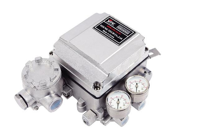
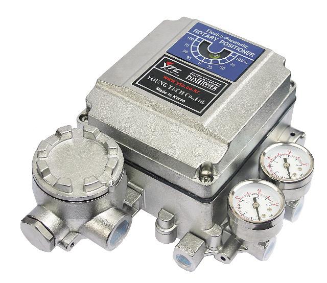
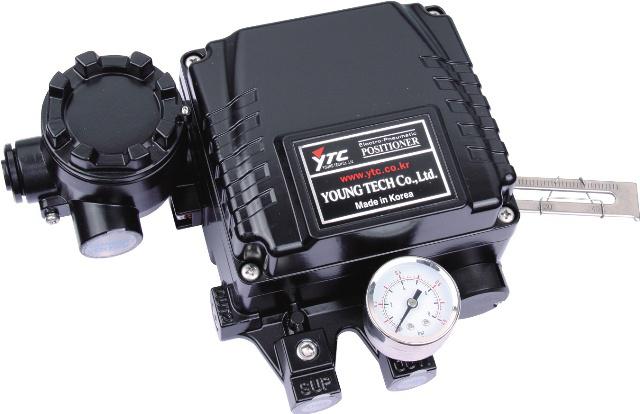
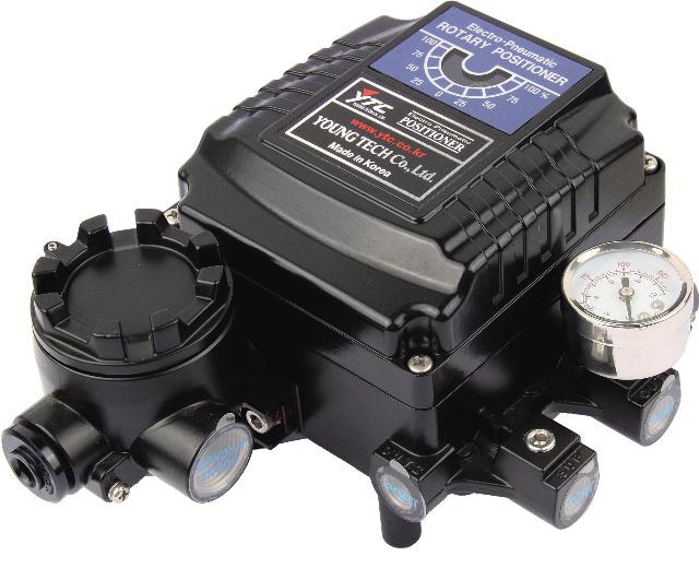
6 2.3 Label Description Fig. 1: YT-1000/1050 Body Label A. Model: Indicates the model number of the positioner. B. Explosion Proof: Indicates certified explosion proof grade. C. Input Signal: Indicates input signal range. D. Amb. Temp.: Indicates the allowable ambient temperature. E. Supply Pressure: Indicates the supply pressure range. F. Serial Number.: Indicates the unique serial number. 2.4 Product Number YT-1000L 6 YT-1000/1050 series
7 2.4.2 YT-1000R 7 YT-1000/1050 series
8 2.4.3 YT YT-1000/1050 series
9 2.5 Product Specification YT-1000L & R Model YT-1000L YT-1000R Acting Type Single Double Single Double Input Signal Impedance Supply Pressure 4~20mA DC 250 +/- 15 Ώ 0.14~0.7 MPa (1.4~7 bar) Stroke 10~150 mm 0~90 Air Connection PT, NPT 1/4 Gauge Connection PT, NPT 1/8 Conduit Entry PF(G) 1/2 Protection Grade IP66 Ex dmb IIB T5 (ATEX) Ex dmb IIC T5 (KTL) Explosion Proof Ambient Temperature Ex ia IIB T6 (KTL) Ex dm IIB T5 (FM) Ex ia IIC T6 (NEPSI) Ex dmb IIC T5/T6 (NEPSI) Operating Temp. :-20~70 (Standard) Explosion Proof Temp. : -40~60 Linearity ±1.0% F.S. ±2.0% F.S. ±1.0% F.S. ±2.0% F.S. Hysteresis ±1.0% F.S. Sensitivity ±0.2% F.S ±0.5% F.S ±0.2% F.S ±0.5% F.S Repeatability Flow Capacity Air Consumption Feedback Signal (Option) Material ±0.5% F.S 80 LPM (Sup.=0.14 MPa) 2.5 LPM (Sup.=0.14 idle) 4~20mA (DC 10~30V) Aluminum Diecasting Weight 2.7 kg 3.5 kg Painting Epoxy Polyestere Powder Coating Tested under ambient temperature of 20 C, absolute pressure of 760mmHg, and humidity of 65%. Please contact Young Tech Co., Ltd for detailed testing specification. * Explosion proof certification is in progress. 9 YT-1000/1050 series
10 2.5.2 YT-1050L & R Model YT-1050L YT-1050R Acting Type Single Double Single Double Input Signal Impedance Supply Pressure 4~20mA DC 250 +/- 15 Ώ 0.14~0.7 MPa (1.4~7 bar) Stroke 10~150 mm 0~90 Air Connection NPT 1/4 Gauge Connection NPT 1/8 Conduit Entry PF(G) 1/2 Protection Grade Explosion Proof Ambient Temperature IP66 Ex dmb IIB T5 (ATEX) Operating Temp. :-20~70 (Standard) Explosion Proof Temp. : -40~60 Linearity ±1.0% F.S. ±2.0% F.S. ±1.0% F.S. ±2.0% F.S. Hysteresis ±1.0% F.S. Sensitivity ±0.2% F.S ±0.5% F.S ±0.2% F.S ±0.5% F.S Repeatability Flow Capacity Air Consumption Feedback Signal (Option) ±0.5% F.S 80 LPM (Sup.=0.14 MPa) 2.5 LPM (Sup.=0.14 idle) 4~20mA (DC 10~30V) Material Stainless Steel 316 Weight 5.7 kg 6.0 kg Tested under ambient temperature of 20 C, absolute pressure of 760mmHg, and humidity of 65%. Please contact Young Tech Co., Ltd for detailed testing specification. * Explosion proof certification is in progress. 10 YT-1000/1050 series

11 2.6 Parts and Assembly YT-1000/1050L YT-1000/1050R 11 YT-1000/1050 series
12 2.6.3 YT-1000L + SPTM (Internal) YT-1000R + SPTM (Internal) 12 YT-1000/1050 series
 13")
13 2.6.5 YT-1000R + L/S (Internal) YT-10000R + SPTM + L/S (Internal) 13 YT-1000/1050 series


14 2.7 Product Dimension YT-1000L Flameproof Type YT-1000L Intrinsically Safety Type YT-1000R Flameproof Type 14 YT-1000/1050 series
 2.7.7 YT-1000R +")

15 2.7.4 YT-1000R Intrinsically Safety Type YT-1000L + SPTM (Internal) YT-1000R + SPTM (Internal) YT-1000R + SPTM + L/S (Internal) & YT-1000R + Dome indicator 15 YT-1000/1050 series

16 2.7.8 YT-1050L YT-1050R 16 YT-1000/1050 series
17 3. Installation 3.1 Safety When installing a positioner, please ensure to read and follow safety instructions. Any input or supply pressures to valve, actuator, and / or to other related devices must be turned off. Use bypass valve or other supportive equipment to avoid entire system shut down. Ensure there is no remaining pressure in the actuator. 3.2 YT-1000/1050L Installation YT-1000/1050L should be installed on linear motion valves such as globe or gate type which uses spring return type diaphragm or piston actuators. Before proceeding with the installation, ensure following components are available. Positioner unit Feedback lever and lever spring Flange nut (bottom side of YT-1000/1050L) 4 pcs x hexagonal headed bolts (M8 x 1.25P) 4 pcs x M8 plate washer Installation Steps 1. Proper bracket must be made in order to adapt the positioner on the actuator yoke. Please consider following important points when a bracket is being designed. Positioner s feedback lever must be parallel to the ground at 50% of the valve stroke. Feedback lever connection with the pin of the actuator clamp should be installed in such a way that the valve stroke length coincides with the corresponding figure in mm marked on the feedback lever. Improper setting may cause poor linearity and may create unnecessary hunting during the operation. 2. Assemble the positioner with the bracket made in previous step by fastening the bolts. Please refer to the backside of the positioner for size of the bolts. The standard bolt size is M8 x 1.25P. Please contact Young Tech Co., Ltd for other bolt sizes. 3. Attach the positioner with bracket to the actuator yoke DO NOT TIGHTEN POSITIONER COMPLETELY. 4. Connect positioner s feedback lever to the actuator clamp. The hole gap on the feedback lever is 6.5mm. The connection pin s outer diameter should be less than 6.3mm. 17 YT-1000/1050 series
18 5. Connect supply pressure to the actuator temporarily. Supply enough supply pressure to the actuator in order to position the actuator clamp at 50% of the total valve stroke. 6. Insert connection pin into the feedback lever. The pin should be inserted when the actuator clamp is at 50% of the total valve stroke. Proper way to connect feedback lever, connection pin, and lever spring 7. Check if feedback lever is parallel to the ground at 50% of the valve stroke. If it is not parallel, adjust the bracket or feedback link bar to make parallel. Improper installation may cause poor linearity and may create unnecessary hunting during the operation. 8. Check the valve stroke. The stroke marks are indicated on the feedback lever of the positioner. Position the connection pin at the number on the feedback lever which corresponds to the desired valve stroke. To adjust, move the bracket, the connection pin or both. Fig. 3: Pin Insertion when valve stroke is 40mm (up) and is 90mm (bottom) 9. After installing the positioner, operate the valve from 0% to 100% stroke by using direct 18 YT-1000/1050 series
19 air to the actuator (manual position). On both 0% and 100%, the feedback lever should not touch the lever stopper, which is located on the backside of the positioner. If the feedback lever touches the stopper, the positioner should be installed further away from the yoke. Fig. 4: Feedback lever should not touch lever stopper 0% ~ 100% valve stroke. 10. After the installation, tighten all of the bolts on the bracket, the feedback lever, and the connection pin. 3.3 YT-1000/1050R Installation YT-1000/1050R should be installed on rotary motion valve such as ball or butterfly type which uses rack and pinion, scotch yoke or other type of actuators which stem rotates 90 degrees. Before proceeding with the installation, ensure following components are available. Positioner unit Fork lever and lever spring Standard rotary bracket (included with the positioner) 4 pcs x hexagonal headed bolts (M8 x 1.25P) 4 pcs x M8 plate washer Fig. 5: Fork lever type (left) and NAMUR lever type (right) Bracket information Standard bracket (included with the positioner) contains two components. The bracket can be used for both fork lever and NAMUR lever type. The bracket is designed to fit onto the actuator with 20mm stem height (H). If actuator s stem height (H) is 30mm or 50mm, bracket must be adjusted. Please refer to below table how to adjust the bracket. 19 YT-1000/1050 series


20 Actuator stem Markings of bolt holes height (H) A-L B-L A-R B-R 20mm H : 20 H : 20, 30 H : 20 H : 20, 30 30mm H : 30 H : 20, 30 H : 30 H : 20, 30 50mm H : 50 H : 50 H : 50 H : Installation Steps 1. Please check the actuator s stem height and adjust the bracket by referring to the bracket table. 2. Attached the bracket onto the actuator. It is recommended to use spring washer so the bolts will not be loosen from vibration. 3. Set rotation position of the actuator stem at 0%. For single acting actuator, it is easy to check 0% point by supplying no pressure to the actuator. For double acting actuator, check actuator stem s rotation direction clockwise or counter-clockwise - by supplying pressure to the actuator. 4. Install the fork lever after setting actuator s stem at 0%. Check the actuator stem s rotation direction clockwise or counter-clockwise. Installation angle of the fork lever should be 45 degrees in relation to the linear shaft. For NAMUR shaft installation, the angle does not matter. Fig. 6: Counter-clockwise and clockwise rotation. 20 YT-1000/1050 series

21 5. After setting fork lever position, assemble lock nuts which are located on the bottom of the fork lever. Ensure to set the height of the upper fork lever between 6~11mm, which is lower than the upper bracket s height. 6. Attach the positioner to the bracket. Fix the clamping pin on the main shaft s center of the positioner and insert connection pin into the fork lever slot. This will lock to the fork lever spring. Setting alignment of the main shaft of the positioner and center of the actuator s stem is very important. Poor alignment of the main shaft and the actuator s stem decreases the positioner s durability due to unnecessary forces on the main shaft. 7. Tighten the positioner and the bracket with hexagon-headed bolts and plate washer after checking the positioner s position. 4. Connections 4.1 Safety Supply pressure should be clean and dry air avoiding moisture, oil or dust. Always recommended to use air filter regulator (i.e. YT-200 series). Young Tech Co., Ltd has not tested positioner s operation with any other gases other than clean air. Please contact Young Tech Co., Ltd for any questions. 4.2 Supply Pressure Condition Dry air with at least 10 lower than ambient temperature. Avoid from dusty air. Positioner s inner filter can only filter 5 micron or larger. Avoid oil. Comply with ANSI/ISA (R1981) or ISA S (R1981). Supply pressure range is 1.4 ~ 7 kgf/cm 2 ( kpa) Set air filter regulator s pressure level 10% higher than actuator s spring range pressure. 4.3 Piping Condition Ensure inside of pipe is clean of obstructions. Do not use pipeline that is squeezed or shows any type of damamges. 21 YT-1000/1050 series


22 Pipeline should have more than 6mm of inner diameter (10mm outer diameter) to maintain flow rate. The length of pipeline system should not be extremely long. Longer pipeline system may affect flow rate due to the friction inside of the pipeline. 4.4 Connection Actuator Single acting actuator Singe acting type positioner is set to use OUT1 port. OUT1 port should be connected with supply pressure port from actuator when using single acting type of spring return actuator. Fig. 7: Singe acting linear (left) and rotary (right) type actuator Double acting actuator Double acting type positioner is set to use OUT1 and OUT2 port. As input signal increases, the supply pressure will be supplied through OUT1 port. Fig. 8: Double acting linear (left) and rotary (right) type actuator 4.5 Connection Power Safety When installing in hazardous and explosive gas area, conduit tube or pressure-proof packing union must be used. The compound charging box should be the flameproof type and must be sealed completely. Conduit entry connection tap is PF 1/2 or G 1/2. Before connecting terminal, ensure that the power is off completely. Do not open the cover when the power is still alive. Please use ring-type rug to protect against vibration or any other external impact. Positioner with PTM options must be supplied 10~28V DC separately. For L/S option, separate 12-24V DC must be supplied. For both options, it should not exceed 30V 22 YT-1000/1050 series

 The outer diameter of the cable should be between 6.35 ~ 10mm.")

23 DC. Positioner should be grounded. Please use twisted cable with conductor section are 1.25mm 2 and that is suitable for 600V (complying to the conductor table of NEC Article 310.) The outer diameter of the cable should be between 6.35 ~ 10mm. Use shield wire to protect against electromagnetic field and noise. Please do not install the cable near high noise equipments, such as high-capacity transformer or motor Ground SPTM Internal <Option> L/S Internal <Option> 23 YT-1000/1050 series


24 4.5.5 SPTM & L/S Internal <Option> 5. Adjustments 5.1 Adjustment Cam YTC sets positioner as Reverse Action <RA> unless specified otherwise when placing an order YT-1000/1050L YT-1000/1050R 24 YT-1000/1050 series

25 5.1.3 YT-1000/1050R with Internal Options <Option> Cam can be adjusted for YT-1000/1050R with options by dissembling the cam from the main shaft. After dissembling the cam from the main shaft, please follow for RA or DA cam. 5.2 Adjustment Zero Point 1. Set supply signal at 4mA or 20mA according to RA or DA and rotate the adjuster up or downward to adjust actuator s initial point. As zero point is being set, the specification of the valve system must be considered. Please refer to diagram on the right to increase or decrease the zero point. 5.3 Adjustment Span 1. After setting zero, supply signal at 20mA or 4mA according to RA or DA and check the actuator stroke. If the stroke is too low, the span should be increased. If the stroke is too high, the span should be decreased. 2. Changing span point will affect zero point setting. Zero point should be set again after span has been adjusted. This step is required until both zero and span are properly set. 3. After proper setting, tighten lock screw. 5.4 Adjustment SPTM <Option> Setting Point Switch There are two types of calibration of SPTM / feedback signal Point Setting This setting only set minimum and maximum point (0% and 100%). In between points 25 YT-1000/1050 series


26 will be calculated automatically Point Setting This setting set 5 points (0%, 25%, 50%, 75%, and 100%). This requires more setting, but feedback setting will be more accurate than 2 point setting Calibration 1. Supply 4mA input signal to the positioner and check if valve position made to its target position. For Direct Action (DA), supply 20mA instead of 4mA for input signal. 2. Press 4mA button on the PCB for 3~4 seconds. LED lamp will blink indicating that the PCB has calibrated the specific position to give 4mA as feedback. 3. Repeat above step for 8mA, 12mA, 16mA, and 20mA. For 2 point setting, only 4mA and 20mA should be set. 5.5 Adjustment L/S <Option> 5.6 Adjustment A/M Switch (Auto/Manual) 1. A/M switch is used when the valve needs to be operated manually. 2. If switch is set as A, the positioner will respond to input signal. If switch is set as M, the positioner will act as bypass and supply pressure to the positioner will directly go to the actuator. 3. Please make sure to set back to A after manual operation. Also, please DO NOT TOUCH SEAT ADJUSTER BOLT ON THE PILOT RELAY. 26 YT-1000/1050 series
27 5.7 Adjustment - Orifice If the actuator size is too small relative to the flow rate, positioner can have hunting / oscillation. In order to avoid hunting, the orifice must be inserted. 1. Remove the pilot relay assembly from the positioner. 2. Remove the o-rings from OUT1 and OUT2 port per above diagram, and insert proper orifice. Before re-assemble the o-rings, please make sure there is no dust or particles remain on the ports. 5.8 Adjustment - Potentiometer External damage or physical shock can dislocate potentiometers factory setting. Potentiometer must be re-calibrated when dislocation of the potentiometer or after cam adjustment. PLEASE REFER BELOW INSTRUCTION AND DIAGRAM. 1. Please set actuator position to 50% of the valve stroke. PLEASE MAKE SURE THAT THE ACTUATOR DOES NOT MOVE DURING THE RE-CALIBRATION. 2. In the junction box, please pull out the potentiometer connector from potentiometer PCB. DO NOT PULL WITH TOO MUCH FORCE AS WIRES CAN BE DAMAGED. 3. On the potentiometer connector, there are three holes. Out of three holes, please measure resistance level by plugging two holes <one of right or left and one of center>. The potentiometer resistance level should be between 0~10 K Ώ and please adjust measurement equipment to measure between above mentioned range. 4. Using + screw driver, loosen potentiometer stopper bolt. DO NOT LOOSEN COMPLETELY. 5. Pull potentiometer behind and potentiometer will be separated from potentiometer gear. This will make user to turn potentiometer gear. 6. Since current actuator position is 50% of the valve stroke, the resistance level should be measure around 5K Ώ (4.8 ~ 4.2 K Ώ) by turning potentiometer gear. 7. After the setting, assemble back the stopper and the bolt. 27 YT-1000/1050 series
28 6. Maintenance Maintenance on pilot relay valve is recommended to perform at least once a year of with or without operation. When dissembling the pilot relay valve, please be careful not to loose any o- rings or stabilizer spring. Please refer to below instruction and diagram. 1. Please remove pilot relay lock bolts. 2. Unlock Auto/Manual (A/M) Switch from the pilot relay. PLEASE MAKE SURE TO REMOVE A/M SWITCH. 3. Remove any particles or dust by blowing air. 28 YT-1000/1050 series
29 7. Troubleshooting Positioner does not respond to the input signal. (1) Check supply pressure level. The lever must be at least 1.4 kgf/cm 2. For spring-return type of actuator, the supply pressure level has to be larger than the spring's specification. (2) Check if input signal is properly supplied to the positioner. The signal should be 4~20mA DC. (3) Check if zero point or span point is properly set. (4) Check if the positioner's nozzle has been blocked. Also, check if the pressure is supplied to the positioner and the pressure is being exhausted through the nozzle. If the nozzle has been block by any substances, please send the product for repair. (5) Check if feedback lever has been installed properly. The pressure of OUT1 reaches exhausting pressure level and does not come back down. (1) Check A/M Switch. If the switch has been damaged, replace the switch or pilot relay valve. (2) Check for a gap or damages between the nozzle and the flapper. If damaged, please send the product to YTC for repair. The pressure is exhausted only by A/M Switch. (1) Check if the positioner's nozzle has been blocked. Also, check if the pressure is supplied to the positioner and the pressure is being exhausted through the nozzle. If the nozzle has been blocked by any substances, please send the product to YTC for repair. Hunting occurs. (1) Check if safety spring has been displaced. (Next to Pilot relay valve) (2) Check if the size of actuator is too small. If so, insert an orifice in order to reduce the pressure flow rate. (3) Check if there is any friction between the valve and the actuator. If so, increase actuator's size or reduce the friction level. Actuator only operates by On/Off. (1) Check actuator and positioner's acting type. Air pressure exhausts from YT-1000L's OUT1 port as input signal level increases. Therefore, it is standard to connect to OUT1 port when single actuator is used. Make sure the span adjustment is properly set according to the valve system. Linearity is too low. (1) Check if positioner is properly positioned. Especially check if the feedback lever is parallel to the ground at 50% point. (2) Check if zero and span point have been properly adjusted. If either one of values is being adjusted, another one must be re-adjusted as well. (3) Check if supply air pressure level is stable from the regulator. If the level is unstable, the regulator must be replaced. Hysteresis is too low. (1) In case of double acting actuator, check if seat adjustment has been properly performed. Please contact YTC for any further inquiries regarding the seat adjustment. (2) Backlash can occur when the feedback lever and lever spring are loosen. To avoid backlashing, please adjust the lever spring. (3) Check if the connection bar to the feedback lever is tightly fastened. 29 YT-1000/1050 series
30 Manufacturer: Young Tech Co., Ltd #3022, Hagun-ri, Yangchon-myeon Kimpo-si, Kyeonggi-do, South Korea Tel: Fax: Copyright Young Tech Co., Ltd. All Rights Reserved. 30 YT-1000/1050 series
31 Pneumatic Positioner YT-1200 Series USER'S MANUAL YTC Ver 1.01
32
33 Introduction Thank you for choosing YTC product. Each product is fully inspected after the production to offer you the highest quality. In order to fully utilize the product, we strongly recommend users to read this manual carefully and understood. The manual should be given to the end-user. The manual can be changed or revised without any prior notice. Any changes in product s specification, structure, and/or any components may not result immediate revised version of the manual. The manual should not be duplicated or reproduced for any purpose without any approvals from Young Tech Co., Ltd, South Korea / YTC. Manufacturer Warranty For the safety, it is imperative to follow instructions in the manual. It is not manufacturer's liability for any damages which caused by users' negligence. It is not manufacturer's liability for any damages or accidents which resulted by any alteration or modification of the product and parts. If alteration or modification is necessary, please contact the manufacturer directly. Manufacturer warrants the product from the date of original retail purchase of the product for eighteen (18) months, except as otherwise stated. Manufacturer warranty will not cover the products that the product have been subjected to abuse, accident, alteration, modification, tampering, negligence, misuse, faulty installation, lack of reasonable care, repair or service in any way that is not contemplated in the documentation for the product, or if the model or serial number has been altered, tampered with, defaced or removed; damages that occurs in shipment, due to act of God, failure due to power surge, and cosmetic damage. Improper or incorrectly performed maintenance or report voids this Limited Warranty. For detailed warranty information, please contact the corresponding local Young Tech Co., Ltd office or main office in South Korea.
34 Product Description Main Features and Functions The product can operate normally in very extreme environment, such as vibration and temperature. The durability has been proven after testing 2 million cycles at the minimum. Response time is very short and accurate. Simple part change can set 1/2 Split Range. It is economical due to less air-consumption. Direct / Reverse action can be set easily. Zero & Span adjustment processes are simple. Feedback connection is easy. Operation Logic Bellows(1) push flapper(2) if input pressure increases. Then the gap between nozzle(3) and flapper(2) increases, which results pressure in upper spool(5) exhaustion. This would cause spool(5) to rise upward. As the spool(5) rises, it pushes format(8), and the air pressure will be supplied to the actuator(10). As the actuator's inner pressure increases, the actuator stem(12) will move. For graphical diagram, please refer to <Figure 1>.

35 Label Description Model: Input Signal: Supply Pressure: Serial Number: Indicates model name and any options (if any) Indicates current input signal range. Indicates the range of supply pressure. Indicates unique serial number. Suffix Symbol YT-1200 series follows suffix symbols as below.
36 Specification
37 Parts and Assembly
38 Dimensions
39 Installation Safety Warning When installing a positioned, please ensure to read and follow safety instruction. All input and supply pressure to valve, actuator, and other related devices must be turned off. Use bypass valve or other equipment to avoid entire system shut down. Make sure there is no remaining pressure in the actuator. Tools for Installation 1 Hexagonal wrench 2 Screw Drivers (+) and (-) 3 Spanners for hexagonal-head bolts YT-1200 Installation YT-1200L should be installed on linear motion valve such as globe valve or gate valve using spring return type diaphragm or piston actuator. Before installation, be sure to check for following installation components. 1 YT-1200L main body 2 Feedback lever and lever spring 3 Flange nut (bottom side of YT-1200L) 4 4 pcs of hexagon head bolts (M8 x 1.25P) 5 4 pcs of M8 plate washer Installation Steps 1. Proper bracket must be made in order to attach positioned on the actuator yoke. Please consider following when making a bracket. A. Feedback lever should be leveled at 50% of the valve stroke. (refer to step G) B. Feedback lever connection bar of the actuator damp should be installed at the positioned that the valve stroke and numbers which indicated on the feedback lever must be fitted. (refer to step H) 2. Attached YT-1200L to the bracket, which was produced in previous step, by using bolts. <Fig 1> Please refer to backside of the unit for size of the bolts. The standard size of bolt is M8 x 1.25P and other bolts sizes are available. Please contact YTC sales department. 3. Attach YT-1200L (with bracket) to the actuator yoke DO
40 NOT TIGHTEN COMPLETELY. 4. Connect YT-1200L feedback lever to the actuator clamp. The gap on the YT-1200L feedback lever is 5mm. The connection bar thickness should be less than.3mm. <Fig 2> 5. Connect air filter regulator to the actuator temporarily. Set supply pressure of the regulator in order to position the actuator damp at 50% of valve stroke. <Fig 3>. Insert connection bar into the YT-1200L feedback lever. The connection bar should be inserted at the 50% point on the feedback lever, which would help to reduce hysteresis. <fig 4>
41 . If connection bar does not point at 50% point, then adjust bracket or feedback link bar position. Failure to position at 50% would lower the linearity of the positioner. <fig 5> 8. Check valve stroke. The stroke numbers are indicated on the feedback lever. Position connection bar at the number on the feedback lever according to the valve stroke. <fig > To adjust, move the bracket or the connection bar. NOTE After installing YT-1200L, operate the valve from 0% to 100% stroke by using air filter regulator. Both of 0% and 100%, the feedback lever should not touch the lever stopper, which is located on the backside of YT-1200L. <fig > If the feedback lever touches the stopper, YT- 1200L should be installed further away from the center of the yoke. 9. After the proper installation, tighten all of the bolts on the bracket, the feedback lever, and the connection bar.
42 YT-1200R Installation YT-1200R should be used for rotary motion valve, that is ball valve, butterfly valve using rack and pinion, scotch yoke or complex type actuator, which its stem rotates 90 degrees. Before installation, be sure to check for following installation components. 1 YT-1200R main body 2 Fork lever and lever spring 3 1 set of bracket (3 pcs) 4 4 pcs of hexagon head bolt M8 x 1.25P 5 4 pcs of M8 plate washer YT-1200R Install Example
43 Bracket Information YT-1200R is supplied with standard bracket. The bracket can be used for fork lever and NAMUR bracket. Please see <fig 8> for more detailed information. 1. Standard actuator stem height (H) is 20, 30, or 50 mm. After check H, assemble with the bracket as shown in <fig 8 & 9> 2. Attached bracketed YT-1200R to the actuator by using hexagonal-headed and wrench bolts. Size of the bracket hole is mm. When tightening bolts, use spring washer or similar for complete attachment to the actuator, so YT-1200R will not be shaken by vibration or any other impact. The direction of bracket is different by the operating condition, but in general, the positioned is installed as shown. <fig 10>
44 3. Set rotation position of the actuator stem at zero point, 0%. For a single type of actuator, it is easy to check zero point, because the actuator stem is positioned at zero point when there is no supply pressure. If double acting actuator is used, check actuator stem s rotation direction (clockwise or counter-clockwise) by supplying pressure. 4. Install the fork lever as shown in <fig11> after setting actuator stem at zero point. Check the direction of the actuator stem clockwise or counter-clockwise. Installation angle of the fork lever should be 45 degrees based on the linear shaft. For NAMUR shaft, the angle does not matter. 5. After setting fork lever position, lock nuts which are assembled on bottom of the fork lever.. Attach YT-1200R to the bracket. Fix the damping pin on the main shaft of YT-1200R and insert connection bar into the fork lever slot, so it can be locked to the fork lever spring. This sets the alignment of the main shaft of YT-1200R and center of the actuator stem. Bad alignment of the main shaft and the actuator stem lowers YT-1200R s durability, because too much force will be on the main shaft of YT-1200R. <fig 12>
45 . Tighten YT-1200R base and the bracket with hexagon-headed bolts and plate washer. It is recommended to tighten four bolts after checking YT-1200R s position. <fig 13>
46 Piping Connection Note To avoid entering moisture, oil, or dust into the product, please carefully make selection of supply pressure compressor. It is recommended to attach air filter regulator <YT-200> before supply port of YT Supply Pressure Condition 1 Dry air with at least 10 lower than ambient temperature. 2 Avoid from dusty air. Filter can only sort 5 micron or larger. 3 Avoid any oil. 4 Comply with ANSI/ ISA (R1981) and ISA S (R1981). 5 Not to be used beyond the range of 1.4 kgf/cm 2 ( kpa). 6 Set air filter regulator s supplied pressure 10% higher than actuator s spring range pressure. Pipe Condition 1 Make sure inside of pipeline is emptied. 2 Do not use pipeline that has been squeezed or has hole. 3 To maintain flow rate, use the pipeline that has more than mm inner diameter. (10mm outer diameter) 4 Do not use extremely long pipeline system. It may affect flow rate due to the friction inside of the pipeline. Piping connection with actuator - Single Acting Actuator YT-1200 series single acting type is set to use OUT1 port. OUT1 port should be connected with supply pressure port from actuator when using single acting type of spring return actuator. <fig 14 & 15>
47 - Double Acting Actuator For YT-1200 series double acting type, when inputting current signal, supply pressure is our from OUT1 port. Please refer to <fig 1 & 1 > Adjustment Adjustment Cam Direction of actuator's stem rotation must be checked when supply signal is supplied. When actuator's stem rotates clockwise, the face of cam must be shown "DA." On the other hand, when the stem rotates counter-clockwise, adjust cam so "RA" shows on the face of cam. Check whether actuator's angle is at the initial point. After checking the initial point, release the hexagonal flange nut and adjust the position of the bearing so it is at 0 point. <Figure 18> When produced, the cam is set as RA.
48 Adjustment Zero Point Set supply signal at 3 psi and rotate adjuster clockwise or counter-clockwise to adjust actuator's rotation angle. <Figure 19> When adjusting zero for single actuator, rotation angle is equal to positioner's pressure gauge. Adjustment Span After setting zero, rotate Span screw so supply signal reaches at the span point on the indicator. Changing span point affects zero point setting. So zero setting must be set again. After setting zero point, confirm the span point. This step must be repeated until both points are properly set. If 1/2 split range is used, YT-1200L can be used after span and zero point are set. For YT-1200R with 1/2 split range, the span spring must be changed. After setting is completed, tighten Lock Screw. <Figure 20>
49 Adjustment A / M Switch <Auto / Manual> 1. A / M switch adjusts the valve operation to automatic or manual. 2. YT-1200 series is set as A / Automatic as default. If user wants to set as M / Manual, the setting can be adjusted by turning the switch counter-clockwise. <fig 21> 3. If the setting is at M, the air pressure will be supplied to the actuator directly. Always set the setting back to A after any change. 4. If OUT2 in single acting actuator or double acting actuator is used, A / M switch will not operate. Adjustment Seat Adjuster 1 Seat adjuster is set according to the customer s request before the positioned is delivered. Please do not adjust the seat adjuster. 2 Seat adjuster is used for double acting actuator. Please do not touch the seat adjuster, because it can affect the positioner s performance.
50 Troubleshooting Positioner does not respond to the input signal. 1 Check supply pressure level. The level must be at least 1.4 kgf/cm 2 2 Check if input signal is properly supplied to the positioned. The signal should be 3-15 psi. 3 Check if the positioner s nozzle has been blocked. Also, check if the pressure is supplied to the positioned and the pressure is being exhausted through the nozzle. If the nozzle has been blocked by any substances, please send the unit to YTC for repair. 4 Check if feedback lever has been installed properly. The pressure of OUT1 reaches exhausting pressure level and does not come back down. 1 Check A / M switch. If the switch has been damaged, replace the switch or pilot relay valve. 2 Check for a gap or damages between the nozzle and the flapper. If damaged, please send the unit to YTC for repair. The pressure is exhausted only by A / M switch. 1 Check if the positioner s nozzle has been blocked. Also, check if the pressure is supplied to the posiioner and the pressure is being exhausted trough the nozzle. If the nozzle has been blocked by any substances, please send the unit to YTC for repair. Hunting occurs. 1 Check if safety spring has been displaced. <Next to pilot relay valve> 2 Check if the size of actuator is too small. If so, insert an orifice in order to reduce the pressure flow rate. 3 Check if there is any friction between the valve and the actuator. If so, increase actuator s size or reduce the friction level. Actuator only operates by on / off. 1 Check pipe connection 2 Check cam direction Linearity is too low. 1 Check if the feedback lever is properly installed. Especially check if the feedback lever is parallel to the around at 50% point. 2 Check if zero and span has been properly adjusted, that is not too low or not too
51 high. 3 Check if supply air pressure level is stable from the regulator. If the level is unstable, replace the regulator. Hysteresis is too low. 1 In case of double acting actuator, check if seat adjustment has been properly done. Please contact YTC for any further inquiries regarding the seat adjustment. 2 Backlash can occur when feedback lever and lever spring is loosen. To avoid backlash, adjust the lever spring. 3 Check if the connection bar to the feedback lever is tightly fastened.
Electro-Pneumatic Positioner YT-1000 / 1050 SERIES
 Electro-Pneumatic Positioner YT-1000 / 1050 SERIES PRODUCT MANUAL VERSION 1.01 Contents 1. Introduction 4 1.1 General information for the users. 4 1.2 Manufacturer Warranty 4 1.3 Explosion Proof Warning.
Pneumatic Positioner PNY Series USER'S MANUAL. Max-Air Technology. Version 1.0
 USER'S MANUAL Max-Air Technology Version 1.0 Table of Contents Introduction 3 Manufacturer Warranty 3 Product Description 4 Main Features and Functions 4 Operation Logic 4 Specification 5 Parts and Assembly
User s Manual. Pneumatic Positioner. Series 58. J Flow. Series 58. J Flow
 Pneumatic Positioner Series 58 User s Manual J Flow Series 58 J Flow Series 58 J Flow Controls, LLC 14 De Camp Cincinnati, OH 45216 Phone: 513-731-2900 Fax 513-731-6939 www.jflowcontrols.com Introduction
RTX1000 SERIES ELECTRO-PNEUMATIC POSITIONER
 RTX1000 SERIES ELECTRO-PNEUMATIC POSITIONER Installation Operation and Maintenance Manual RTX-IOM-RTX1000/1000L-R01-0416 Page 1 of 26 Contents 1. Introduction... 4 1.1. General information... 4 1.2. Definitions...
SMART POSITIONER YT-2400 SERIES USER'S MANUAL
 SMART POSITIONER YT-2400 SERIES USER'S MANUAL YTC V.1.02 1 Table of Contents Contents Page No. Introduction 4 Manufacturer Warranty 4 Product Description 5 Main Features and Functions 5 Label Description
YT-1200 Series VERSION 1.02
 YT-1200 Series PRODUCT MANUAL VERSION 1.02 Contents 1. Introduction... 4 1.1 General Information for the users... 4 1.2 Manufacturer Warranty... 4 1.3 Explosion Proof Warning (Only for external explosion
Pneumatic Positioner RTX - Series USER S MANUAL. ROTEX P/P Ver. 0.1 Dated: MAY / 2009 REV 01: SEP/2010 Page 1 of 16
 Pneumatic Positioner RTX - Series USER S MANUAL MODEL RTX 1200 AMBIENT TEMP. 20 C ~ 70 C WEATHER PROOF IP 65 SUPPLY PR. 1.4 ~ 7.0 bar INPUT SIGNAL 0.2 ~ 1.0 bar SERIAL NO. ROTEX P/P Ver. 0.1 Dated MAY
SMART POSITIONER YT-2300 SERIES USER'S MANUAL
 SMART POSITIONER YT-2300 SERIES USER'S MANUAL Table of Contents Contents Page No. Introduction 4 Manufacturer Warranty 4 Product Description 5 Main Features and Functions 5 Label Description 6 Suffix Symbols
VOLUME BOOSTER RELAYS YT-310 / 315 SERIES
 VOLUME BOOSTER RELAYS YT-310 / 315 SERIES PRODUCT MANUAL VERSION 1.02 Contents 1. Introduction 3 1.1 General information for the users. 3 1.2 Manufacturer Warranty 3 2. Product Description.. 4 2.1 General..
YT-720 SERIES. Rotork YTC Limited VERSION 1.07
 YT-720 SERIES PRODUCT MANUAL YT-720S YT-720D Rotork YTC Limited VERSION 1.07 Contents 1. Introduction... 3 1.1 General Information for the users... 3 1.2 Manufacturer Warranty... 3 1.3 Explosion Proof
Electro-Pneumatic Positioner RTX - Series USER S MANUAL. ROTEX E/P Ver. 0.1 Dated: dd / mm / yy Page 1 of 18
 Electro-Pneumatic Positioner RTX - Series USER S MANUAL ROTEX E/P Ver. 0.1 Dated dd / mm / yy Page 1 of 18-1 - RTX1000-R2-2011 Table of Contents Introduction 3 Manufacturer Warranty 3 General Service Information
SMART POSITIONER YT-2500/2501/2550 SERIES
 SMART POSITIONER YT-2500/2501/2550 SERIES PRODUCT MANUAL VERSION 1.03 Contents 1. Introduction 5 1.1 General information for the users. 5 1.2 Manufacturer Warranty 5 2. Product Description.. 6 2.1 General..
Pneumatic-Pneumatic Positioner YT-1200L,R Installation manual
 Installation Safety Warning When installing a positioned, please ensure to read and follow safety instruction. All input and supply pressure to valve, actuator, and other related devices must be turned
Operation Manual Electro-Pneumatic Positioner Model: NT-1000R (Rotary Type) NUTORK CORPORATION
 NUTORK CORPORATION") Operation Manual Electro-Pneumatic Positioner Model: NT-1000R (Rotary Type) Integral Mounted Air Set Dome Indicator NUTORK CORPORATION Table of Contents Introduction 2 Manufacturer Warranty Product Description
Operation Manual Electro-Pneumatic Positioner Model: NT-1000R (Rotary Type) Integral Mounted Air Set Dome Indicator NUTORK CORPORATION Table of Contents Introduction 2 Manufacturer Warranty Product Description
SMART POSITIONER YT-3400 SERIES
 SMART POSITIONER YT-3400 SERIES USER'S MANUAL 1 V.1.02 Table of Contents Introduction 4 Manufacturer Warranty 4 Product Description 5 Main Features and Functions 5 Label Description 6 Suffix Symbol 7 Specification
SMART POSITIONER YT-3300/3301 SERIES
 SMART POSITIONER YT-3300/3301 SERIES PRODUCT MANUAL VERSION 1.02 Contents 1. Introduction 5 1.1 General information for the users. 5 1.2 Manufacturer Warranty 5 2. Product Description.. 6 2.1 General..
YT-1000 / 1050 Series
 YT-1000 / 1050 Series PRODUCT MANUAL VERSION 1.07 Contents 1. Introduction... 5 1.1 General Information for the users... 5 1.2 Manufacturer Warranty... 5 1.3 Explosion Proof Warning (Only for explosion
Smart Positioner YT-2400L,R Installation manual
 Installation Safety Warning When installing a positioner, please ensure to read and follow safety instruction. All input and supply pressure to valve, actuator, and other related devices must be turned
SMART POSITIONER SS3400 SERIES
 SMART POSITIONER SS3400 SERIES PRODUCT MANUAL VERSION 1.03 Contents 1. Introduction 4 1.1 General information for the users. 4 1.2 Manufacturer Warranty 4 1.3 Explosion Proof Warning. 3 2. Product Description..
SMART POSITIONER YT-2500 SERIES USER'S MANUAL
 SMART POSITIONER YT-2500 SERIES USER'S MANUAL YTC V.1.01 1 Table of Contents Introduction 4 Manufacturer Warranty 4 Product Description 5 Main Features and Functions 5 Label Description 6 Suffix Symbol
YT-200 / 205 / 220 / 225 Series YT-200 YT-205 YT-220 YT-225 VERSION 1.01
 YT-200 / 205 / 220 / 225 Series PRODUCT MANUAL YT-200 YT-205 YT-220 YT-225 VERSION 1.01 Contents 1. Introduction... 3 1.1 General Information for the users... 3 1.2 Manufacturer Warranty... 3 2. Product
SMART POSITIONER YT-3400 / 3450 SERIES PRODUCT MANUAL
 SMART POSITIONER YT-3400 / 3450 SERIES PRODUCT MANUAL VERSION 1.03 Contents 1. Introduction 4 1.1 General information for the users. 4 1.2 Manufacturer Warranty 4 1.3 Explosion Proof Warning. 3 2. Product
SMART POSITIONER YT-2500/2550 SERIES USER'S MANUAL
 SMART POSITIONER YT-2500/2550 SERIES USER'S MANUAL YTC 1 V.1.04 Table of Contents Introduction 4 Manufacturer Warranty 4 Product Description 5 Main Features and Functions 5 Label Description 6 Suffix Symbol
YT-520S YT-520D YT-525S YT-525D YT-530S YT-530D YT-535S YT-535D
 YT-520 / 525 / 530 / 535 Series PRODUCT MANUAL YT-520S YT-520D YT-525S YT-525D YT-530S YT-530D YT-535S YT-535D VERSION 1.04 Rotork YTC Limited Contents 1 Introduction...3 1.1 General Information for the
SMART POSITIONER 6000/6050 SERIES
 SMART POSITIONER 6000/6050 SERIES PRODUCT MANUAL VERSION 1.00 Contents 1. Introduction 5 1.1 General information for the users. 5 1.2 Manufacturer Warranty 5 2. Product Description.. 6 2.1 General.. 6
Electro-Pneumatic Linear Positioner Installation and Operation Instructions B GB
 Installation and Operation Instructions 99.66.02-B GB Description of Device (4-~20mA) is the advanced control device for a linear control valve that provides unparalleled stability in difficult environments
Installation- Linear. I & M Mark 17X Series. Mark 17X Linear Installation
 I & M Mark 17X Series 3170 Wasson Road Cincinnati, OH 45209 Phone 513.533.5600 Fax 513.871.0105 (f) info@richardsind.com www.jordanvalve.com Installation & Maintenance Instructions for the Mark 17X Series
SP-20 Input. Installation and Operating Instructions Electro-Pneumatic Linear Positioner. Description of Device. Part Number System
 Description of Device VALMAC Posi-Zest SP-2000 Series is the advanced control device for a linear control valve that provides unparalleled stability in difficult environments. Easy maintenance Precise
YT-2600 SERIES VERSION 1.07
 SMART POSITIONER YT-2600 SERIES PRODUCT MANUAL VERSION 1.07 Contents 1. Introduction... 4 1.1 General Information for the users... 4 1.2 Manufacturer Warranty... 4 1.3 Explosion Proof Warning & Specific
YT-2500 / 2550 / 2501 SERIES
 SMART POSITIONER YT-2500 / 2550 / 2501 SERIES PRODUCT MANUAL VERSION 1.10 Contents 1. Introduction... 5 1.1 General Information for the users... 5 1.2 Manufacturer Warranty... 5 1.3 Explosion Proof Warning
Series 60. New Smart Positioner. Compact design Convenient & powerful function Enhanced reliability
 Series 60 New Smart Positioner Compact design Convenient & powerful function Enhanced reliability J Flow Controls, LLC 14 De Camp Cincinnati, OH 45216 Phone: 513-731-2900 Fax 513-731-6939 www.jflowcontrols.com
Installation and Operating Instructions Electro-Pneumatic Rotary Positioner SP-21. Description of Device. Part Number System
 Description of Device VALMAC Posi-Zest SP-2100 Series is the advanced control device for a rotary control valve that provides unparalleled stability in difficult environments. Easy Maintenance Precise
POSITIONERS and Controls for Complete Valve Automation
 CONTROLS A Division of AT Controls Pneumatic & Electro-Pneumatic POSITIONERS and Controls for Complete Valve Automation 1 SS SERIES SS Features Easy and quick auto-calibration Detecting RA (reverse acting)
Moniteur INSTALLATION & OPERATING INSTRUCTIONS. SERIES 40 Positioners. Installation and Operating Instructions Series 40 Positioners.
 INSTALLATION & OPERATING INSTRUCTIONS SERIES 40 Positioners Form IO2-0406 Description of Device Moniteur's Series 40 pneumatic (3-15psi) and electropneumatic (4-20mA) positioners are advanced control devices
AP ATEX AIRPOWER POSITIONERS AP2000 FEATURES AP1000 & AP1200 FEATURES OPTIONS OPTIONS
 AP1000-2000 Airpower positioners are a robust range of rotary or linear valve positioners in AP1000 electro-pneumatic (4-20mA), AP1200 pneumatic (3-15 psi) or AP2000 programmable smart type. Designed to
INSTRUCTION MANUAL. CVS Series 3400 Flameproof Smart Positioner. Introduction
 INSTRUCTION MANUAL CVS Series 3400 Flameproof Smart Positioner Introduction The CVS 3400 is a CSA approved and Explosion Proof Rated EX d IIC T6/T5, Class 1, Zone 1, Group A. Additional certifications
YT-3300 / 3350 / 3303 / 3301 SERIES
 SMART POSITIONER YT-3300 / 3350 / 3303 / 3301 SERIES PRODUCT MANUAL YT-3300 YT-3300 with limit switch YT-3350 YT-3303 YT-3303 YT-3301 VERSION 1.11 Contents 1. Introduction... 5 1.1 General Information
CVS 2400 SERIES SMART POSITIONER
 CVS 2400 SERIES SMART POSITIONER Product Manual PRODUCT DRIPTION YT-2400 Smart Valve Positioner accurately controls valve stroke according to input signal of 4~20mA input from a controller. In addition,
TMP-3000 VERSION 1.01
 VERSION 1.01 Contents 1. Introduction... 4 1.1 General Information for the users... 4 1.2 Safety precautions and Manufacturer Warranty... 4 2. Product Description... 5 2.1 General... 5 2.2 Main Features
Instruction and Operating Manual
 Instruction and Operating Manual Electro-Pneumatic Positioner Power-Genex Ltd. Contents 1. Safety Instructions / Precautions 2 2. Description 7 3. Description 7 4. Specifications 8 5. Part Numbering System
Series 185/285 Smart Positioners
 Series 185/285 Smart Positioners Bulletin V-185/285 Specifications - Installation and Operating Instructions DOUBLE ACTION SINGLE ACTION LCD SCREEN SMART POSITIONER 3-47/64 [95.00] Series 185 3-27/32 [97.50]
SS3 Linear / Rotary. Smart Valve Positioner. Smart performance with innovative and ever-strong coil drive even under harsh working environments
 Smart Valve Positioner SS3 Linear / Rotary Smart performance with innovative and ever-strong coil drive even under harsh working environments Easy and quick auto-calibration Detecting RA (reverse acting)
PRODUCTS CATALOG (2018) TISSIN CO.,LTD. Smart Valve Positioner. Electro-Pneumatic Positioner. Volume Booster. Lock Up Valve. Air Filter Regulator
 TISSIN CO.,LTD. Smart Valve Positioner. Electro-Pneumatic Positioner. Volume Booster. Lock Up Valve. Air Filter Regulator") PRODUCTS CATAOG (08) TISSIN CO.,TD. Smart Valve Positioner Electro-Pneumatic Positioner Volume Booster ock Up Valve Air Filter Regulator Solutions for control valve system About Tissin Solutions for control
PRODUCTS CATAOG (08) TISSIN CO.,TD. Smart Valve Positioner Electro-Pneumatic Positioner Volume Booster ock Up Valve Air Filter Regulator Solutions for control valve system About Tissin Solutions for control
Type Installation, Operation and Maintenance Instructions. Ordering Information. Contents CA20 -
 Type 2000 Pneumatic and Electropneumatic Valve Positioner Installation, Operation and Maintenance Instructions Ordering Information Use this coding system to order Model CA20 - Type of Positioner 00 P/P
Electro-Pneumatic Positioner Series 830/831-WP/EX. Operation & Maintenance Manual
 Electro-Pneumatic Positioner Series 830/831-WP/EX Operation & Maintenance Manual Electro-Pneumatic Positioner Model 830/831- WP/EXP This operation & maintenance manual corresponds to Forbes Marshall Arca
Fig Single-Acting Rotary Smart Positioner
 Fig. 3303 Single-Acting Rotary Smart Positioner Order Information Model No. EC03303RSN52000S Econ series 3300 Smart Positioner for quarter turn actuators in single acting version. This positioner regulates
V200 Series Positioners
 V200 Series Positioners In a single compact and rugged housing The V200 positioner incorporates the flexibility of converting from a pneumatic unit to several versions of an electropneumatic unit, and
TOP-QUALITY PNEUMATIC ACTUATOR
 TOP-QUALITY PNEUMATIC ACTUATOR BS EN ISO 9001:2000 INTRODUCTION PDS series Pneumatic Actuators are designed using Scotch-Yoke technology from PDS 50 to the largest of PDS 200. Scotch-Yoke technology is
V200 Series Positioners
 V200 Series Positioners In a single compact and rugged housing The V200 positioner incorporates the flexibility of converting from a pneumatic unit to several versions of an electropneumatic unit, and
SMART VALVE POSITIONER 4 to 20 ma + HART Digital Communication. smar B87
 SMART VALVE POSITIONER to ma + HART Digital Communication B87 DESCRIPTION The FY microprocessor based positioner provides fast and accurate positioning of diaphragm or cylinder actuators. The FY produces
Features. Flexibility
 The V100 positioner can be ordered as a base model pneumatic positioner, converted to standard NEMA 4X electropneumatic, EX model, or FF (fail freeze) model in a matter of minutes, without removing the
TECHNICAL BULLETIN. Logix 510si Series Digital Positioner. Experience In Motion FCD LGENTB /09
 Logix 510si Series Digital Positioner TECHNICAL BULLETIN FCD LGENTB0510-01 09/09 Experience In Motion Introduction The Logix 510si series are single acting, user-friendly digital positioners. As all positioners
SS2 Linear / Rotary Smart Valve Positioner
 COTROLS A Division of AT Controls Smart performance with innovative and ever-strong coil drive even under harsh working environments Also available in REMOTE TYPE 316 STAILESS STEEL BODY Smart performance
CONTROL VALVE ACCESSORIES CVA : 0611 ELECTRO PNEUMATIC / PNEUMATIC POSITIONER POSITION TRANSMITTER SIL
 ELECTRO PNEUMATIC / PNEUMATIC POSITIONER POSITION TRANSMITTER CVA : 0611 SIL Next generation of Positioner design featuring better performance and ease of setup has taken ELECTRO-PNEUMATIC POSITIONER RTX1000
Valve Positioners Series 760P/E Valve Positioners
 Introduction Features & Benefits Universal design and choice of interchangeable AMUR IEC 54-6 rectilinear or VDI/VDE 845 rotary mountings provide wide application flexibility Double-acting or single-acting
VALVE ACCESSORIES & CONTROLS V200 POSITIONER A POSITIONER THAT OFFERS IT ALL IN ONE COMPACT, SIMPLE, HOUSING
 VALVE ACCESSORIES & CONTROLS V200 POSITIONER A POSITIONER THAT OFFERS IT ALL IN ONE COMPACT, SIMPLE, HOUSING WWW.VACACCESSORIES.COM 205-678-0507 The V200 Positioner Internal I/p with simple loop test points.
Corrosion Resistant Pneumatic Positioners Model 4700P and 4700E
 Corrosion Resistant Pneumatic Positioners Specification Data CS2007 4/98 Table of Contents Foreword............................................................. 2 Numbering System.....................................................
NOAH ACTUATOR NA-SERIES MANUAL EMICO EUNHA MACHINERY INDUSTRIAL CO.,LTD.
 NOAH ACTUATOR NA-SERIES MANUAL EMICO EUNHA MACHINERY INDUSTRIAL CO.,LTD N A Table of Contents 1. Caution 2 2. Storage 4 3. Actuator Specification 5 4. Standard Specification 7 5. Optional Specification
OM Field-Type I/P Converter Model : KUX113 User's Manual
 OM2-5900-1130 Field-Type I/P Converter Model : KUX113 User's Manual Copyright, Notices and Trademarks 1994-2012 Azbil Corporation All Rights Reserved. While this information is presented in good faith
Control Valves Positioner
 Control Valves Positioner HiFlo Valve Positioner Easy calibration Corrosion-resistant cover and base Withstands 150 psi at all parts Two -sided cam for easy field reversibility Optional / NPT for piped
Control Valves Positioner
 Control Valves Positioner HiFlo HiFlo Valve Positioner Corrosion-resistant cover and base Easy calibration Withstands 150 psi at all parts Two -sided cam for easy field reversibility Optional / NPT for
Valtek XL Series High Performance Positioner. for Control Valves
 Valtek XL Series High Performance Positioner for Control Valves Features Easy calibration Ground Screw Corrosion-resistant cover and base Simple signal conversion with interchangeable modules Split ranges
V200 Series Positioners
 V200 Series Positioners In a single compact and rugged housing The V200 incorporates the flexibility of converting from a pneumatic unit to several versions of an electropneumatic unit, and the ability
Pneumatic or Electropneumatic Positioner for Rotary Actuators Type Fig. 1 Type 3761 Positioner. Mounting and Operating Instructions EB 8386 EN
 Pneumatic or Electropneumatic Positioner for Rotary Actuators Type 3761 Fig. 1 Type 3761 Positioner Mounting and Operating Instructions EB 8386 EN Edition June 2004 Contents Contents Page 1 Design and
SINGLE-ACTING ACTUATORS FOR DOUBLE-ACTING & SERIES 65 POSITIONERS PNEUMATIC & ELECTRO-PNEUMATIC. The High Performance Company
 POSITIONERS PNEUMATIC & SERIES 65 FOR DOUBLE-ACTING & SINGLE-ACTING ACTUATORS The High Performance Company SERIES 65 FEATURES The Brayline Series 65Pneumatic and Electro-Pneumatic Positioner feature modular
V200 POSITIONER. Datasheet
 atasheet 1 CONTENTS 1 INTOUCTION... 3 1.1 Principle of Operation... 3 1.2 Product Identification... 3 1.3 Air quality recommendations... 4 1.4 Safety Instructions... 4 2 INSTALLATION... 5 2.1 Connections...
Smart Valve explorer Smart Valve Positioner for Rotary Valve. Model SVX100 / SVX102
 No. SS2-SVX100-0100 Smart Valve explorer Smart Valve Positioner for Rotary Valve Model SVX100 / SVX102 OVERVIEW Smart Valve explorer (SVX) models SVX100 and SVX102 are microprocessor-equipped, currentpneumatic
Spring Cylinder Rotary Actuator
 Spring Cylinder Rotary Actuator Rotary Actuator Spring Cylinder Rotary Actuators High torque and pneumatic stiffness combine together in the Mascot "Spring cylinder rotary actuator" These characteristics
ITVX Series. Stepless control of air pressure proportional to an electrical signal. Supply pressure: 5.0 MPa
 5.0 MPa Maximum Supply Pressure High Pressure Electro-Pneumatic Regulator X Series This product is only for blowing gas. This product does not have sufficient pressure control for other applications (driving,
ABB MEASUREMENT & ANALYTICS DATA SHEET. AV1 and AV2 Characterizable pneumatic and electro-pneumatic positioners
 ABB MEASUREMENT & ANALYTICS DATA SHEET AV1 and AV2 Characterizable pneumatic and electro-pneumatic positioners 2 AV 1 AN D AV 2 CH AR ACTER I Z ABLE PNE U MATIC POSITIONE RS DS/AV 1 2-E N RE V. I Measurement
Instruction and Operating Manual
 M/SS2/E 01 2011 Instruction and Operating Manual Smart Valve Positioner SS2L / SS2R Series Contents 1. Introduction 2 11.5 Sub-Parameters Flow Diagram 2. Overview of Structure 3 11.5.1 Change of Input
Type 4746 Electric or Pneumatic Limit Switch
 Type 4746 Electric or Pneumatic Limit Switch Application Limit switches with inductive, electric or pneumatic contacts for attachment to pneumatic or electric control valves, to Type 4763 Electropneumatic
PMV P36C AND P41C POSITIONERS ACTUATORS
 PMV P36C AND P41C POSITIONERS USED WITH DeZURIK PNEUMATIC ACTUATORS Instruction D10327 August 2012 Instructions These instructions provide information about Models P36C and P41C PMV Positioners. They are
ELECTRONIC CONTROL ACTUATOR
 ELECTRONIC CONTROL ACTUATOR Nucom Series LINEAR TYPE Nucom L25 Nucom L50 OPERATION MANUAL Koei Industry Co., Ltd. FOR YOUR SAFETY In order for better and safety use of the product for a long period, please
fact sheet Masoneilan * 8012/8013 Series Electro-pneumatic Valve Positioners GE Oil & Gas Excellent Dynamic Response and Positioning Accuracy
 GE Oil & Gas Masoneilan * 8012/8013 Series Electro-pneumatic Valve Positioners fact sheet Excellent Dynamic Response and Positioning Accuracy Accurate, Simple, Rugged The primary function of a valve positioner
Type Type 1001 Transducers. I/P & E/P Transducers
 Type 1001 I/P & E/P Description The Type 1001 is a patented family of electropneumatic instruments that is used to reduce a supply pressure to a regulated output pressure which is directly proportional
Operating Instructions. Pneumatic Control Valve Low Temperature. Type Series GS3
 Operating Instructions Pneumatic Control Valve Low Temperature Type 8026 Series GS3 With: Digital Positioner Type 8048 Electro-pneumatic Positioner Type 8047 Pneumatic Positioner Type 8047 Version: 03/2006
Installation & Operation Manual
 Installation & Operation Manual (I-TORK PDS Series Pneumatic Actuator) PDS-M0108/1010 74-6, Chun Ui-Dong, Won Mi-Gu, Bucheon, Kyoung Ki-Do, Korea Tel : 82-2-855-1365, 66 Fax : 82-2-855-1367 E-mail : roy75@i-tork.com
Valve Positioners Series 760P/E Valve Positioners
 Introduction Features & Benefits Universal design and choice of interchangeable AMUR IEC 54-6 rectilinear VDI/VDE 845 rotary mountings provide wide application flexibility Double-acting or single-acting
SMART VALVE POSITIONER 4 to 20 ma + HART Digital Communication. smar
 SMART VALVE POSITIONER to ma + HART Digital Communication smar DESCRIPTION The FY microprocessor based positioner provides fast and accurate positioning of diaphragm or cylinder actuators. The FY produces
TOP-QUALITY PNEUMATIC ACTUATOR
 TOPQUALITY PNEUMATIC ACTUATOR BS EN ISO 9001:2000 INTRODUCTION PDS series Pneumatic Actuars are designed using ScotchYoke technology from PDS 50 the largest of PDS 200. ScotchYoke technology is well known
Type 3761 Pneumatic or Electropneumatic Positioner for Rotary Actuators. Fig. 1 Type 3761 Positioner. Mounting and Operating Instructions EB 8386 EN
 Type 3761 Pneumatic or Electropneumatic Positioner for Rotary Actuators Fig. 1 Type 3761 Positioner Mounting and Operating Instructions EB 8386 EN Edition July 2007 Contents Contents Page 1 Design and
4.3 MSK SWITCH BOX MSK (SIZE I) FEATURES ADVANTAGES
 FEATURES ADVANTAGES") SWITCH BOX MSK (SIZE I) FEATURES - A compact, robust switch box to be mounted on pneumatic actuators - Position response via integrated micro limit switches - Integrated terminal Strip - The micro limit
SWITCH BOX MSK (SIZE I) FEATURES - A compact, robust switch box to be mounted on pneumatic actuators - Position response via integrated micro limit switches - Integrated terminal Strip - The micro limit
Pneumatic cylinder CC Series (Ø200 Ø350)
") Pneumatic cylinder CC Series (Ø200 Ø350) Installation Operation and Maintenance Manual RTX-IOM-CC Series (Ø200 Ø350)-R01-0316 Page 1 of 22 Contents 1. Introduction... 3 1.1. Definitions... 4 2. Operation
Pneumatic cylinder CC Series (Ø200 Ø350) Installation Operation and Maintenance Manual RTX-IOM-CC Series (Ø200 Ø350)-R01-0316 Page 1 of 22 Contents 1. Introduction... 3 1.1. Definitions... 4 2. Operation
TZIM. Electropneumatic Analog Positioner 10/ EN
 TZIM Electropneumatic Analog Positioner EP001XA.tif Q Convenient, simple design Q Easy to handle Q User-friendly operation, easy to understand Q Reliable concept, I/P conversion through the 500,000 times
BUS DOOR SYSTEM ELECTRO-PNEUMATIC IN-SWING BUS DOOR CONTROL MECHANISM
 BUS DOOR SYSTEM ELECTRO-PNEUMATIC IN-SWING BUS DOOR CONTROL MECHANISM Installation Operation and Maintenance Manual RTX-IOM-BDOS-R01-0216 Page 1 of 18 Table of Contents 1. Introduction... 3 1.1. Definitions...
Valtek Beta Positioner. Valtek Beta Positioners. for Control Valves
 Valtek Beta Positioners for Control Valves 1 Features Easy calibration Corrosion-resistant cover and base Simple signal conversion with interchangeable modules Independent zero and span settings Split
Operation and Maintenance Instructions Manual BOOSTER. Volume amplifier
 Operation and Maintenance Instructions Manual BOOSTER Volume amplifier 1. GENERAL INFORMATION... 3 2. TECHNICAL SPECIFICATIONS... 3 3. DIMENSIONAL DESIGN... 4 3.1 BOOSTER WITHOUT SIGNAL ADAPTER... 4 3.2
Smart Valve Positioner 100 Series Model AVP100/102
 CM2-AVP100-2001 Smart Valve Positioner 100 Series Model AVP100/102 User's Manual NOTICE While the information in this manual is presented in good faith and believed to be accurate, Azbil Corporation disclaims
FloWing Eccentric Rotary type Control Valves. Model: VFR (6-inch or more) User s Manual
 User s Manual") FloWing Eccentric Rotary type Control Valves Model: VFR (6-inch or more) User s Manual OM2-8130-0200 6th edition Copyright, Notices and Trademarks 2012 Azbil Corporation All Rights Reserved. While this
FloWing Eccentric Rotary type Control Valves Model: VFR (6-inch or more) User s Manual OM2-8130-0200 6th edition Copyright, Notices and Trademarks 2012 Azbil Corporation All Rights Reserved. While this
Versions. Version with K VS Version with K VS 2.0. Fig. 1: Type 3967 Solenoid Valve
 Type 367 Solenoid Valve Application Solenoid valve for controlling pneumatic linear actuators with NAMUR rib according to IEC 60534 or pneumatic rotary actuators with NAMUR interface according to VDI/VDE
 Flow Line Controls Positioner Specifications Series 55 3-15 psi Pneumatic Series 56 4-20 ma Electro-Pneumatic Series 55 Series 56 Flow Line Controls, Inc. P.O. Box 677 Schriever, LA 70395 Phone: 985-414-6003
ELECTRONIC CONTROL ACTUATOR
 ELECTRONIC CONTROL ACTUATOR Nucom Series LINEAR TYPE Nucom L50S OPERATION MANUAL Koei Industry Co., Ltd. FOR YOUR SAFETY In order for better and safety use of the product for a long period, please observe
Fisher 3710 and 3720 Positioners and 3722 Electro Pneumatic Converter
 Product Bulletin D200437X012 3710 and 3720 Positioners Fisher 3710 and 3720 Positioners and 3722 Electro Pneumatic Converter Fisher 3710 pneumatic (figure 1) and 3720 electro pneumatic positioners (figure
Fisher i2p 100 Electro Pneumatic Transducer
 Product Bulletin D103197X012 i2p 100 Transducer Fisher i2p 100 Electro Pneumatic Transducer The Fisher i2p 100 electro pneumatic transducer, shown in figure 1, uses a converter module that converts a milliampere
ELECTRONIC CONTROL ACTUATOR
 ELECTRONIC CONTROL ACTUATOR Nucom Series LINEAR TYPE Nucom L100 OPERATION MANUAL Koei Industry Co., Ltd. FOR YOUR SAFETY In order for better and safety use of the product for a long period, please observe
The EP5 electropneumatic positioner is
 EP5 Electropneumatic Positioner The EP5 electropneumatic positioner is adapted from the PMV P5 pneumatic positioner. This compact and sturdy unit is designed for maximum performance in all types of environments.
EB EN. Type 3372 Electropneumatic Actuator. Translation of original instructions
 EB 8313-1 EN Translation of original instructions V2001-IP Control Valve Type 3372 0511/0531 Electropneumatic Actuator with Type 3321 Valve Type 3372 Electropneumatic Actuator Edition July 2013 Note on
Smart Valve Positioner 700 Series with HART Communication Protocol
 No. SS2-AVP702-0100 Smart Valve Positioner 700 Series with HART Communication Protocol OVERVIEW The Smart Valve Positioner 700 Series (model number: AVP7**) not only inherits the reliability of the core
Instruction. MI June E69F Current-to-Pneumatic Signal Converter
 Instruction MI 018-430 June 2005 E69F Current-to-Pneumatic Signal Converter ! DANGER This converter may have agency certification for installation in hazardous locations or for intrinsic safety. Use of