YT-1000 / 1050 Series
|
|
|
- Oscar Brown
- 5 years ago
- Views:
Transcription


1 YT-1000 / 1050 Series PRODUCT MANUAL VERSION 1.07
2 Contents 1. Introduction General Information for the users Manufacturer Warranty Explosion Proof Warning (Only for explosion proof type positioners) Product Description General Main Features and Functions Label Description Product Code YT-1000 Linear series follows suffix symbols as follows YT-1000 Rotary series follows suffix symbols as follows YT-1050 series follows suffix symbols as follows Product Specification Positioner Specification Specification of SPTM(Smart Position Transmitter) option Specification of Internal L/S(Limit Switch) option Specification of External L/S option Certifications YT-1000 & YT YT YT SPTM-6V(External option) YT-870(External option) Parts and Assembly YT-1000L YT-1050L YT-1000R YT-1000R + SPTM (Internal) YT-1000R + Limits Switch (Internal) YT-1000R + SPTM (External) YT-1000R + Limit Switch (External) Product Dimension YT-1000L (Flameproof enclosure) YT-1000L (Non-explosion proof type or Intrinsic safety) YT-1000L (Internal SPTM without LCD) YT-1000R (Fork Lever type + Explosion proof construction for internal pressure) YT-1000R (Namur type) YT-1000R (Dome indicator) Ver
3 2.8.7 YT-1000R (Internal SPTM without LCD) YT-1000R (Internal SPTM with LCD) YT-1000R (Internal Limit Switch or Limit Switch + SPTM) YT-1000R (External SPTM with LCD) YT-1000R (External Limit Switch) YT-1050L (Explosion proof construction for internal pressure type) YT-1050R (Fork Lever type + Explosion proof construction for internal pressure) principle of positioner movement Linear Positioner Rotary Positioner Installation Safety Tools for installation Linear positioner Installation Preparing Bracket for the positioner Installation Steps Rotary positioner Installation Components Rotary Bracket Information Rotary positioner Installation Steps Connection - Air Safety Supply Pressure Condition Piping Condition Connection Piping with actuator Single action Double acting actuator Connection Power General Flameproof enclosure type Safety Connection Intrinsic safety type Connection Internal SPTM (Without LCD) Slide Switch Buttons Internal SPTM (With LCD) Internal L/S + SPTM (Without LCD) Adjustments Ver
4 7.1 Ra or Da Setting Linear Positioner Rotary positioner Adjustment - Zero Point Adjustment - Span Adjustment L/S (Limit Switch, Internal, Option) Adjustment A/M switch (Auto/Manual) Orifice Installment Reset Potentiometer Maintenance Pilot valve Seals Troubleshooting Ver
5 1. Introduction 1.1 General Information for the users Thank you for purchasing Young Tech Co., Ltd products. Each product has been fully inspected after its production to offer you the highest quality and reliable performance. Please read the product manual carefully prior to installing and commission the product. The manual should be provided to the end-user. The manual can be altered or revised without any prior notice. Any changes in product s specification, design, and/or any components may not be printed immediately but until the following revision of the manual. When the manual refers to Valve Zero / Zero means the final valve position upon pneumatic pressure has been fully exhausted from positioner s OUT1 port. For example, the valve zero position may differ between linear direct and reverse actions. (DA/RA) The manual should not be duplicated or reproduced for any purpose without prior approval from Young Tech Co., Ltd, Gimpo-si, South Korea. In case of any other problems that are not stated in this manual, please make immediate contact to Young Tech co., Ltd. Positioner is an accessory of the control valve, so please make sure to read the applicable instruction manual of the control valve prior to installation and operation. 1.2 Manufacturer Warranty For the safety, it is important to follow the instructions in the manual. Manufacturer will not be responsible for any damages caused by user s negligence. Any modifications or repairs to the product may only be performed if expressed in this manual. Injuries and physical damages caused by customer s modifying or repairing the product without a prior consultation with Young Tech co., Ltd will not be compensated. If any alterations or modifications are necessary, please contact Young Tech Co., Ltd directly. Manufacturer warrants the product from the date of original purchase of the product for eighteen (18) months, except as otherwise stated. Manufacturer warranty will not cover products that have been subjected to abuse, accidents, alterations, modifications, tampering, negligence, misuse, faulty installation, lack of reasonable care, repair or service in any way that is not contemplated in the documentation for the product, or if the model or serial number has been altered, tampered with, defaced or removed; damages that occurs in shipment, due to act of God, failure due to power surge, or cosmetic damage. Improper or incorrectly performed maintenance will void this limited warranty. For detailed warranty information, please contact the corresponding local Young Tech Co., Ltd office or main office in South Korea. Ver
6 1.3 Explosion Proof Warning (Only for explosion proof type positioners) Please ensure the unit is being used and installed in conformity with local, regional, and national explosion proof environment. Refer to 2.6 Certifications Explosion proof type of cables and gaskets should be used, when explosion gases are present at the installation site. Power should be turned off completely when opening product s cover. When opening the cover, ensure that there is no power remaining in any electrical parts nearby. Flameproof enclosure type positioner has 2 ports for power connection. Explosion proof type wires and packing should be used. Blind plug is required when any port is not being used. Ring terminal with surface area of more than 0.195mm 2 with M4 spring washer should be used to connect the power. For external ground terminal, ring terminal with surface area of more than 5.5mm 2 should be used. There is risk of explosion due to static electricity charge. Static electricity charge may develop when cleaning the product with a dry cloth. It is imperative to avoid static electricity charge in the hazardous environment. If cleaning the surface of the product is needed, must use wet clothes. To meet explosion-proof marking information and ingress protection of IP66, use certified Ex-cable glands and Ex-plugs. If you need additional information about the values of the flameproof joints, contact Young Tech Co., Ltd directly. Ver
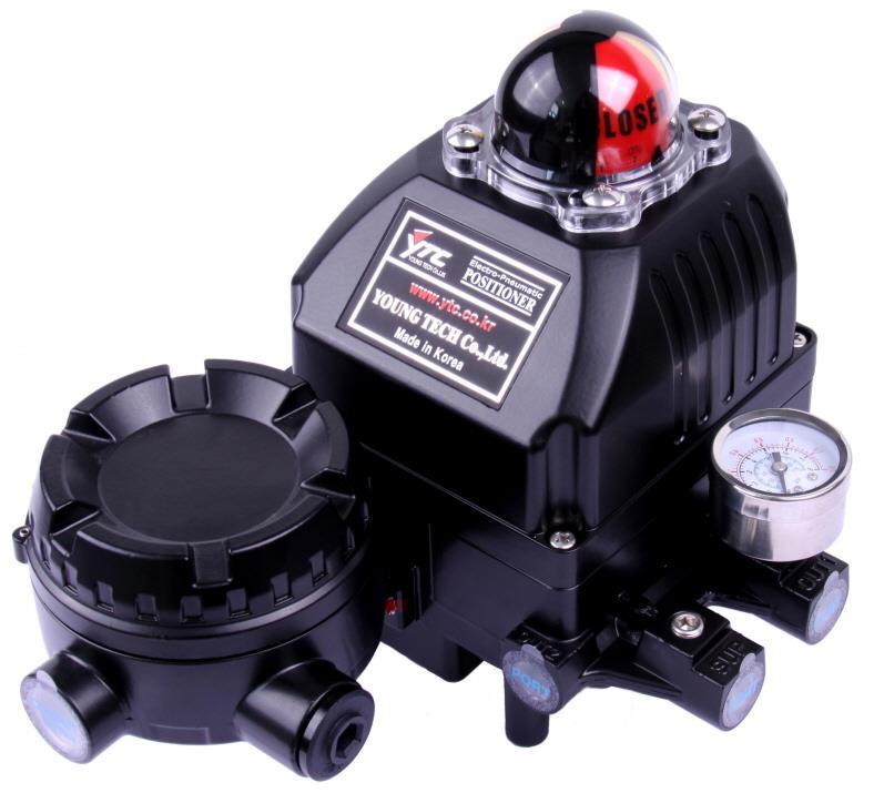
7 2. Product Description 2.1 General Electro-Pneumatic Positioner accurately controls valve stroke in response to an input signal of 4~20mA from the controller. 2.2 Main Features and Functions It is compatible with most of controllers. Response time is very fast and accurate. Split range 4~12mA or 12~20mA can be set by simple operating. Low air consumption. Simple Direct / Reverse Action change. Simple Zero & Span adjustment. Internal & External options, such as position transmitter (PTM) and/or limit switch (L/S) are available. (Internal options are for non-explosion proof and External options are for explosion proof.) Orifices can be installed even in the field to minimize the hunting occurrence and optimize operating conditions. A/M switch can be used to direct supply air to the actuator or to manually operate the positioner or valve without any signal. It has IP66, Type 4X (FM) ingress protection grade. Epoxy polyester powder coating resists the corrosion process. (except YT-1050). Maintenance of the positioner is easy because of modularized inner structure. Ver

 to the sticker nameplate. Printed contents may be erased.")
8 2.3 Label Description MODEL : Indicates the model number and any options of the positioner. EXPLOSION PROOF : Indicates certified explosion proof grade. INGRESS PROTECTION : Indicates enclosure protection grade. INPUT SIGNAL: Indicates input signal range. OPERATING TEMP. : Indicates the allowable operating temperature. AMBIENT TEMP. : Indicates the allowable ambient temperature for explosion proof. SUPPLY PRESSURE : Indicates the supply pressure range. SERIAL NUMBER : Indicates unique serial number. YEAR : Indicates manufactured year. Precautions Be careful not to apply volatile solvent (hardener of instant adhesive, acetone, WD-40, etc.) to the sticker nameplate. Printed contents may be erased. Fig. L-1: YT-1000 Non-explosion Fig. L-2: YT-1000 Ex db mb IIB T5 Gb (ATEX, IECEx, TS) Fig. L-3: YT-1000 Ex dmb IIB T4 (KCs) Ver
 Fig.")
 Fig.")
 Fig.")
 Ver.")
9 Fig. L-4: YT-1000 Ex dmb IIC T5 (KCs) Fig. L-5: YT-1000 Ex ia IIB T6 Gb (KCs) Fig. L-6: YT-1000 Ex d mb IIC T6 Gb (NEPSI) Fig. L-7: YT-1000 Ex ia IIC T6 Ga (NEPSI) Ver
 Fig.")


 Fig.")
10 Fig. L-8: YT-1000 Ex dmb IIB T5 (TIIS) Fig. L-9: YT-1000 XP-S/I/1/CD/T5; DIP/II,III/1/EFG/T5 (FM) Fig. L-10: YT-1000 Class I, Zone 1, Ex d m IIB T5 (CSA) Fig. L-11: YT-1000 Non-explosion (TRCU) Ver
")
")


11 Fig. L-12: YT Ex d mb IIB T5 Gb X (TRCU) Fig. L-13: YT-1000 Ex db mb IIB T5 Gb (INMETRO) Fig. L-14: YT-1050 Non-explosion Fig. L-15: YT-1050 Ex db mb IIB T5 Gb (ATEX, IECEx, KCs) Ver
12 2.4 Product Code YT-1000 Linear series follows suffix symbols as follows. YT-1000L Acting type S : D : 2 Explosion Proof N : M : A : C : i : X : E : 3 Lever Type 1 : 2 : 3 : 4 : 4 Orifice Type 1 : 2 : 3 : Single Double Non-explosion ATEX, IECEx, TS, KCs, INMETRO FM, CSA KCs, NEPSI KCs TIIS TRCU 10 ~ 40 mm 30 ~ 70 mm 60 ~ 100 mm 100 ~ 150 mm Ø1 Ø2 None 5 Conduit Air Connection Type 1 : 2 : 3 : 4 : 5 : G 1/2 - PT 1/4 G 1/2 - NPT 1/4 G 1/2 - G 1/4 M20*1.5P - NPT 1/4 NPT 1/2 - NPT 1/4 6 Operating Temp. S : H : L : 7 Option 0 : 2 : 3 : -20 C ~ 70 C (-4 F ~ 158 F) -20 C ~ 120 C (-4 F ~ 248 F) Non-explosion -40 C ~ 70 C (-40 F ~ 158 F) Non-explosion except KCs None + SPTM (Smart Position Transmitter) Non-explosion + SPTM with LCD Non-explosion Ver
13 2.4.2 YT-1000 Rotary series follows suffix symbols as follows. YT-1000R Acting type S : D : 2 Explosion Proof N : M : A : C : i : X : E : 3 Lever Type 1 : 2 : 3 : 4 : 5 : 4 Orifice Type 1 : 2 : 3 : Single Double Non-explosion ATEX, IECEx, TS, KCs, INMETRO FM, CSA KCs, NEPSI KCs TIIS TRCU M6 x 34L M6 x 63L M8 x 34L M8 x 63L Namur Ø1 Ø2 None 5 Conduit Air Connection Type 1 : 2 : 3 : 4 : 5 : G 1/2 - PT 1/4 G 1/2 - NPT 1/4 G 1/2 - G 1/4 M20*1.5P - NPT 1/4 NP T1/2 - NPT 1/4 6 Operating Temp. S : H : L : 7 Option 1 0 : 1 : 8 Option 2 0 : 1 : 2 : 3 : 4: 5: 6: -20 C ~ 70 C (-4 F ~ 158 F) -20 C ~ 120 C (-4 F ~ 248 F) Non-explosion -40 C ~ 70 C (-40 F ~ 158 F) Non-explosion except KCs Standard Cover Dome Cover None + SPTM (Internal, Without LCD) Non-explosion + SPTM (External, With SPTM-6V) Non-explosion + L/S (Limit Switch, Internal) Non-explosion + L/S (External, With YT-870) Non-explosion + SPTM + L/S (Internal, Without LCD) Non-explosion + SPTM + L/S (External, With YT-870) Non-explosion Ver
14 2.4.3 YT-1050 series follows suffix symbols as follows. YT Motion type L : R : 2 Acting type S : D : 3 Explosion Proof N : M : E : Linear Rotary Single Double Non-explosion ATEX, IECEx, KCs, INMETRO TRCU 4 Lever Type Linear 1 : 2 : 3 : 4 : 10 ~ 40 mm 20 ~ 70 mm 50 ~ 100 mm 100 ~ 150 mm Rotary 1 : 2 : 3 : 4 : 5 : M6 x 34L M6 x 63L M8 x 34L M8 x 63L NAMUR 5 Orifice Type 1 : 2 : 3 : Ø1 Ø2 None 6 Conduit Air Connection Type 2 : G 1/2 - NPT 1/4 7 Operating Temp. S : H : L : -20 C ~ 70 C (-4 F ~ 158 F) -20 C ~ 120 C (-4 F ~ 248 F) Non-explosion -40 C ~ 70 C (-40 F ~ 158 F) Non-explosion Ver
15 2.5 Product Specification Positioner Specification Model YT-1000 YT-1050 Housing Material Aluminum Stainless steel 316 Motion Type Linear Rotary Linear Rotary Acting Type Input Signal Supply Pressure Single / Double 4~20mA DC 0.14 ~ 0.7 MPa (1.4 ~ 7 bar) Stroke 10 ~ 150 mm 0 ~ ~ 150 mm 0 ~ 90 Impedance Max. 250 ± 15Ω Air Connection PT(G or NPT) 1/4 NPT 1/4 Gauge Connection PT(or NPT) 1/8 NPT 1/8 Conduit Entry G(PF) 1/2 or NPT 1/2 or M20*1.5P G(PF) 1/2 Ingress Protection Explosion Proof IP66, Type 4X 1. Non-explosion 2. Ex db mb IIB T5 Gb 2. Ex db mb IIB T5 Gb (ATEX, IECEx, TS) (ATEX, IECEx, KCs) 3. 1Ex d mb IIB T5 Gb X 3. Ex dmb IIC T5 (KCs) (TRCU) 4. Ex ia IIB T6 Gb (KCs) 4. Ex db mb IIB T5 Gb 5. Ex d mb IIC T6 Gb (NEPSI) (INMETRO) 6. Ex dmb IIB T5/T4 (KCs) 7. Ex dmb IIB T5 (TIIS) 8. Ex d m IIB T5 (FM, CSA) 9. 1Ex d mb IIB T5 Gb X (TRCU) 10. Ex db mb IIB T5 Gb (INMETRO) Refer to 2.6 certifications for details Standard -20 C ~ 70 C (-4 F ~ 158 F) Ambient Temperature Operating High Low -20 C ~ 120 C (-4 F ~ 248 F) -40 C ~ 70 C (-40 F ~ 158 F) Linearity Explosion proof Single Double Refer to 2.6 certifications for details ±1% F.S. ±2% F.S. Hysteresis Sensitivity Repeatability Flow Capacity Air Consumption Single Double ±1% F.S. ±0.2% F.S ±0.5% F.S ±0.5% F.S. 80 LPM (Sup.=0.14 MPa) 2.5 LPM (Sup.=0.14 idle) Feedback Signal (Option) 4~20mA (DC 9~28V) Weight 2.7 Kg (6.1 lb) 2.8 Kg (6.2 lb) 5.71 Kg (12.6 lb) Painting Epoxy Polyester Powder Coating - Tested under ambient temperature of 20 C, absolute pressure of 760mmHg, and humidity of 65%. Please contact Young Tech Co., Ltd for detailed testing specification. Ver
16 External Internal Electro-Pneumatic Positioner Specification of SPTM(Smart Position Transmitter) option External SPTM Model SPTM-6V Housing Material Aluminum Motion Type Linear Rotary Input Signal 10 ~ 150 mm (0 ~ 30 ) 0 ~ 90 Output Signal 4~20mA DC External Load Resistance Rext (Vs-9) / 20mA, 750 = 24V Supply Voltage Vs : 9 ~ 28V DC Linearity ±1% F.S. Hysteresis ±0.2% F.S. Sensitivity ±0.2% F.S Conduit Entry G(PF) 1/2 Ingress Protection IP67 Ambient Temperature Explosion Proof Operating LCD Operating Explosion proof Ex d IIC T6 (KCs) Refer to certifications -40 C ~ 85 C (-40 F ~ 185 F) -30 C ~ 85 C (-22 F ~ 185 F) -40 C ~ 60 C (-40 F ~ 140 F) Weight 1.3 Kg (2.9 lb) Painting Epoxy Polyester Powder Coating Tested under ambient temperature of 20 C, absolute pressure of 760mmHg, and humidity of 65%. Please contact Young Tech Co., Ltd for detailed testing specification. Ver
17 2.5.3 Specification of Internal L/S(Limit Switch) option Switch Type Mechanical Switch (2 x SPDT) Micro Switch Model V-165-1A5 (OMRON) Switch Rating AC 250V 16A DC 125V 0.6A, 250V 0.3A Terminal 8 Points Tested under ambient temperature of 20 C, absolute pressure of 760mmHg, and humidity of 65%. Please contact Young Tech Co., Ltd for detailed testing specification Specification of External L/S option External L/S Model Housing Material YT-870 Aluminum Switch Type Mechanical Type (2 x SPDT) Inductive Proximity Sensor Micro Switch Model Switch Rating Terminal AC DC SS5GL (OMRON) 250V 3A, 125V 5A SS10GL (OMRON) 250V 10.1A, 125V 10.1A 250V 0.2A, 125V 0.4A, 30V 4A, 14V 5A, 8V 5A PS17-5DU (Autonics) NJ2-V3-N (P&F) ~24V 8.2V 8 Points Conduit Entry NPT 3/4 (G 3/4, M20, NPT 1/2) Ingress Protection Explosion Proof Ambient Temperature Weight Painting IP67 Flameproof enclosure. Refer to Certifications -20 C ~ 60 C (-4 F ~ 140 F) 1.5 Kg (3.3 lb) Epoxy Polyester Powder Coating Tested under ambient temperature of 20 C, absolute pressure of 760mmHg, and humidity of 65%. Please contact Young Tech Co., Ltd for detailed testing specification. Mechanical Type (2 x DPDT) DZ-10G-1B (OMRON) 125 or 250V 10A, 480V 2A 125V 0.5A, 250V 0.25A Ver
18 2.6 Certifications All certifications below are posted on YTC homepage( YT-1000 & YT-1050 ATEX Rating : II 2G Ex db mb IIB T5 Gb, NEMA 4X Certification No. : EPS 16 ATEX X Ambient temperature : -20 ~ 60 C (-4 ~ 140 F) IECEx Rating : Ex db mb IIB T5 Gb, NEMA 4X Certification No. : IECEx EPS X Ambient temperature : -20 ~ 60 C (-4 ~ 140 F) TRCU (Russia, Kazakhstan, Belarus) Rating : 1Ex d mb IIB T5 Gb X, IP66 Certification No. : RU C-KR.MЮ62.B Ambient temperature : -40 ~ 60 (-40 ~ 140 F) INMETRO (Brazil) Rating : Ex db mb IIB T5 Gb Certification No. : DNV X Ambient temperature : -20 ~ 60 (-4 ~ 140 F) YT-1000 KCs 1) Rating : Ex dmb IIB T5/T4 Certification No. : 10-KB2BO-0028 Ambient temperature : -20 ~ 70 C (-4 ~ 158 F) 2) Rating : Ex dmb IIC T5 IP66 Certification No. : 11-KB2BO-0014 Ambient temperature : -40 ~ 70 C (-40 ~ 158 F) 3) Rating : Ex ia IIB T6 Gb Certification No. : 11-KB2BO-0001X Ambient temperature : -40 ~ 70 C (-40 ~ 158 F) NEPSI 1) Rating : Ex d mb IIC T6 Gb Certification No. : GYJ X 2) Rating : Ex ia IIC T6 Ga Certification No. : GYJ X Ver
19 FM Rating : XP-S/I/1/CD/T5 Ta=60 C; DIP/II,III/1/EFG/T5 Ta=60 C; Type 4X Original Project ID : Ambient temperature : -20 ~ 60 C (-4 ~ 140 F) CSA Rating : Ex d m IIB T5 Gb Certification No. : Ambient temperature : -40 ~ 60 C (-40 ~ 140 F) TIIS Rating : Ex dmb IIB T5 Certification No. : TC21196 Ambient temperature : -20 ~ 70 C (-4 ~ 158 F) TS Rating : Ex db mb IIB T5 Gb X Certification No. : TS : Ambient temperature : -20 ~ 60 C (-4 ~ 140 F) Electromagnetic Compatibility (EMC) - EMC directive 2014/30/EC from April EC Directive for CE conformity marking YT-1050 KC (Korea) Rating : Ex dmb IIB T5 Certification No. : 10-KB2BO-0029 Ambient temperature : -20 ~ 70 C (-4 ~ 158 F) Ver
20 2.6.4 SPTM-6V(External option) KC (Korea) Rating : Ex d IIC T6 IP67 Certification No. : 12-KB2BO-0313 Ambient temperature : -40 ~ 60 C (-40 ~ 140 F) Electromagnetic Compatibility (EMC) - EMC directive 2014/30/EC from April EC Directive for CE conformity marking YT-870(External option) KC (Korea) Rating : Ex d IIC T6 Certification No. : 12-KB2BO-0093 Ambient temperature : -20 ~ 60 C (-4 ~ 140 F) ATEX Rating : II 2G Ex db IIC T6 Gb, II 2D Ex tb IIC T85 C Db Certification No. : EPS 16 ATEX X Ambient temperature : -20 ~ 60 C (-4 ~ 140 F) IECEx Rating : Ex db IIC T6 Gb, Ex tb IIIC T85 C Db Certification No. : IECEx EPS X Ambient temperature : -20 ~ 60 C (-4 ~ 140 F) CSA Rating : Ex db IIC T6 Class I, Zone 1, AEx db IIC T6 Class II, Division 1, Groups E, F and G; Ex tb IIIC T85 C Zone 21, AEx tb IIIC T85 C Certification No. : Ambient temperature : -20 ~ 60 C (-4 ~ 140 F) Electromagnetic Compatibility (EMC) - EMC directive 2014/30/EC from April EC Directive for CE conformity marking Ver


21 2.7 Parts and Assembly YT-1000L YT-1050L Ver

 Ver.")
22 2.7.3 YT-1000R YT-1000R + SPTM (Internal) Ver
 Ver. 1.")
23 2.7.5 YT-1000R + Limits Switch (Internal) Ver
 2.7.")
 Ver.")
24 2.7.6 YT-1000R + SPTM (External) YT-1000R + Limit Switch (External) Ver
 2.")
 Ver. 1.")
25 2.8 Product Dimension YT-1000L (Flameproof enclosure) YT-1000L (Non-explosion proof type or Intrinsic safety) Ver
 2.8.")

26 2.8.3 YT-1000L (Internal SPTM without LCD) YT-1000R (Fork Lever type + Explosion proof construction for internal pressure) Ver
 2.8.")
 Ver. 1.")
27 2.8.5 YT-1000R (Namur type) YT-1000R (Dome indicator) Ver


28 2.8.7 YT-1000R (Internal SPTM without LCD) YT-1000R (Internal SPTM with LCD) Ver
 Ver.")
29 2.8.9 YT-1000R (Internal Limit Switch or Limit Switch + SPTM) Ver
 Ver. 1.")
30 YT-1000R (External SPTM with LCD) Ver
 Ver. 1.")
31 YT-1000R (External Limit Switch) Ver
 2.")
")
32 YT-1050L (Explosion proof construction for internal pressure type) YT-1050R (Fork Lever type + Explosion proof construction for internal pressure) Ver

33 3. principle of positioner movement 3.1 Linear Positioner Fig. 3-1: Linear positioner with an actuator When INPUT SIGNAL is supplied to the positioner to open the valve, power is generated from 1 the torque motor and pushes 2 the flapper to the opposite side of 3 the nozzle. The gap between 3 the nozzle and 2 the flapper becomes wider and from inner part of 4 the pilot, air inside 9 the chamber is exhausted through 3 the nozzle. Due to this effect 5 the spool moves to the right. Then, 7 the seat which was blocked by 8 the poppet pushes the poppet away and supplied pressure (air) goes through 7 the seat and OUT1 Port and enters into 10 the chamber of the actuator. Then 10 chamber s pressure will increase and when there is enough pressure inside the chamber to push 11 the actuator s spring, 12 actuator s stem will start to go down and through the feedback lever, stem s linear motion will be converted to span 14 lever s rotary motion. This 14 span lever s rotary motion will then once again rotate 15 the span and pulls the spring. When the valve s position reaches to given input signal, 16 span spring s pulling force and 1 torque motor s power will be balanced and move 2 the flapper back its original position to reduce the gap between 3 the nozzle. The amount of air being exhausted through 3 the nozzle will reduce and 9 the chamber pressure will increase again. 5 Spool will move back to its original position on the left and 8 the poppet will also move in same direction blocking 7 the seat to stop the air coming into the 10 chamber through the SUPPLY. As a result, the actuator will stop operating and the positioner will return to its normal condition. Ver

34 3.2 Rotary Positioner Fig. 3-2: Rotary positioner with an actuator When INPUT SIGNAL is supplied to the positioner to open the valve, power is generated from 1 the torque motor and pushes 2 the flapper to the opposite side of 3 the nozzle. The gap between 3 the nozzle and 2 the flapper becomes wider and from inner part of 4 the pilot, air inside 9 the chamber is exhausted through 3 the nozzle. Due to this effect 5 the spool moves to the right. Then, 7 the seat which was blocked by the poppet pushes 8 the poppet away and supplied pressure (air) goes through 7 the seat and OUT1 Port and enters into 10 the chamber of the actuator through OUT1. Then 10chamber s OUT1 pressure will increase and 11 the actuator s stem will rotate and through 12 the feedback shaft, actuator s rotating motion will be transferred to 13 the cam. This motion will then rotate 14 the span lever and pull 15 the span s spring. Once it reaches to given input signal, 15 span spring s pulling force and 1 torque motor s power will be balanced and move 2 the flapper back its original position to reduce the gap between 3 the nozzle. The amount of air being exhausted through 3 the nozzle will reduce and 9 chamber pressure will increase again. 5 Spool will move back to its original position on the left and 8 the poppet will also move in same direction blocking 7 the seat to stop the air coming into the 10 chamber through the SUPPLY. As a result, the actuator will stop operating and the positioner will return to its normal condition. Ver

35 4. Installation 4.1 Safety When installing a positioner, please ensure to read and follow safety instructions. Any input or supply pressures to valve, actuator, and / or to other related devices must be turned off. Use bypass valve or other supportive equipment to avoid entire system shut down. q Ensure there is no remaining pressure in the actuator. The positioner has a vent cover to exhaust internal air and drain internal condensation water. When installing the positioner, make sure the vent cover must be facing downward. Otherwise, the condensation water could cause corrosions and damages to internal parts. Fig. 4-1: The correct positions of a vent cover Installed in accordance with the National Electrical Code(NEC), ANSI/NFPA 70, or CEC Part 1 as applicable.(fm approved product) 4.2 Tools for installation Hex key set for hex socket cap bolts (+) & (-) Screw drivers Spanners for hexagonal-head bolts Ver

36 4.3 Linear positioner Installation Linear positioner should be installed on linear motion valves such as globe or gate type which uses spring return type diaphragm or piston actuators. Fig. 4-2: Installation example Before proceeding with the installation, ensure following components are available. Positioner Feedback lever and lever spring M6 nut and spring washer (fastening feedback lever to a main shaft) Bracket, bolts and washers for positioner not supplied with the positioner Connection bar not supplied with the positioner Preparing Bracket for the positioner Proper bracket must be made in order to adapt the positioner on the actuator yoke. Please consider following important points when a bracket is being designed. Positioner s feedback lever must be vertical to the valve stem at 50% of the valve stroke. The connection bar of the actuator clamp for the feedback lever should be installed in such a way that the valve stroke length coincides with the corresponding figure in mm marked on the feedback lever. Improper setting may cause poor linearity Ver
. Fig. 4-3: Attaching positioner to bracket Fig. 4-4: Attaching the bracket to actuator yoke 2.")

37 4.3.2 Installation Steps 1. Assemble the positioner with the bracket made in previous step by fastening the bolts (M8 * 1.25P). Fig. 4-3: Attaching positioner to bracket Fig. 4-4: Attaching the bracket to actuator yoke 2. Attach the positioner with the bracket to the actuator yoke DO NOT TIGHTEN THE BRACKET COMPLETELY. 3. Connect connection bar to the actuator clamp. The hole gap on the feedback lever is 6.5mm so the connection bar s outer diameter should be less than 6mm. Ver


38 4. Connect an air-filter regulator to the actuator temporarily. Supply enough air pressure to the actuator in order to position the valve stroke at 50% of the total stroke. Fig. 4-5: Positioning the valve at 50% of the total stroke 5. Insert the connection bar between the feedback lever and lever spring. The connection bar must be located upward from the lever spring as shown the below left figure. If it is located downward from the lever spring as shown the below right figure, the connection bar or the lever spring will be worn out quickly because of excessive strong tension. Fig. 4-6: Proper way to insert connection bar between feedback lever and lever spring Ver

39 6. Check if feedback lever is vertical to the valve stem at 50% of the valve stroke. If it is not vertical, adjust the bracket or the connection bar to make vertical. Improper installation may cause poor linearity. Fig. 4-7: Feedback lever and valve stem 7. Check the valve stroke. The stroke numbers are engraved on the feedback lever of the positioner. Position the connection bar at the number on the feedback lever which corresponds with the desired valve stroke. To adjust, move the bracket, the connection bar or both. The effective linear lever angle is 23 degree. Stroke : 30mm Stroke : 70mm Fig. 4-8: Feedback lever and location of the connection bar Ver

40 8. After installing the positioner, operate the valve from 0% to 100% stroke by using direct air to the actuator. On both 0% and 100%, the linear lever stopper should not touch the stopping bosses of positioner, which is located on the backside of the positioner. If the linear lever stopper touches the stopping bosses, the positioner should be installed further away from the yoke. Fig. 4-9: Linear lever stopper should not touch stopping bosses of positioner on 0% ~ 100% valve stroke. 9. After the installation, tighten all of the bolts or nuts on the bracket and the connection bar. Ver

41 4.4 Rotary positioner Installation Rotary positioner should be installed on rotary motion valve such as ball or butterfly type which uses rack and pinion, scotch yoke or other type of actuators which its stem rotates 90 degrees. Before proceeding with the installation, ensure following components are available Components Positioner Fork lever (Only Fork lever type) Rotary bracket set (2 piece) 4 pcs x hexagonal headed bolts (M8 x 1.25P) 4 pcs x M8 plate washers 4 pcs x wrench headed bolts (M6 x 1P x 15L) 4 pcs x M6 nuts 4 pcs x M6 spring washers Bolts and washers to attach bracket to actuator not supplied with the positioner Fig. 4-10: Fork lever type Fig. 4-11: Namur type Ver
 contains two components.")
 according to VDI/VDE 3845 standard.")

42 4.4.2 Rotary Bracket Information The rotary bracket set(included with the positioner) contains two components. The bracket is designed to fit onto the actuator with 20mm, 30mm and 50mm stem height (H) according to VDI/VDE 3845 standard. Please refer to below figures how to adjust the height of the bracket. Fig. 4-12: Brackets and positioner Fig. 4-13: Actuator stem Height Fig. 4-14: Rotary Brackets Assembly Ver

43 4.4.3 Rotary positioner Installation Steps 1. Please check the actuator s stem height and adjust the brackets by referring to the above bracket figures. 2. Attached the brackets onto the actuator. It is recommended to use spring washer so the bolts will not be loosen from vibration. 3. Set rotation position of the actuator stem at 0%. For single acting actuator, it is easy to check 0% point by supplying no pressure to the actuator. For double acting actuator, check actuator stem s rotation direction clockwise or counter-clockwise - by supplying pressure to the actuator. 4. (Only Fork lever type) Install the fork lever after setting actuator s stem at 0%. Check the actuator stem s rotation direction clockwise or counter-clockwise. Installation angle of the fork lever should be 45 to the longitudinal direction of the actuator. Fig. 4-15: Counter-clockwise and clockwise rotation. Ver
 20 About 44 30 About 54 50 About 74 Fig. 4-16: Height of fork lever 6.")
 of the main shaft of the positioner into the hole of center of the fork lever. The clamping pin will be locked to the fork lever spring.")
44 5. (Only Fork lever type) After determining fork lever direction, adjust F between the top plate of fork lever and the top face of actuator as below table. Fasten lock nuts which are located on the bottom of the fork lever. H F (only No. 1 & 3 fork lever) 20 About About About 74 Fig. 4-16: Height of fork lever 6. Attach the positioner to the bracket. <Only fork lever type : Fix the clamping pin (5mm Dia.) into the fork lever slot and insert center pin (2mm Dia.) of the main shaft of the positioner into the hole of center of the fork lever. The clamping pin will be locked to the fork lever spring.> Setting alignment of center of main shaft of the positioner and center of the actuator s stem is very important. Poor alignment of the main shaft and the actuator s stem decreases the positioner s durability due to unnecessary forces on the main shaft. Fig. 4-17: Main shaft center alignment (Fork lever) Fig. 4-18: Main shaft center alignment (Namur) 7. Tighten the positioner and the bracket with bolts after checking the positioner s position. Ver
45 5. Connection - Air 5.1 Safety Supply pressure should be clean and dry air avoiding moisture, oil and dust. Always recommended to use air filter regulator (i.e. YT-200 series). Young Tech Co., Ltd has not tested positioner s operation with any other gases other than clean air. Please contact Young Tech Co., Ltd for any questions. 5.2 Supply Pressure Condition Dry air with dew point of at least 10 lower than ambient temperature. Avoid from dusty air. Use 5 micron or smaller filter. Avoid oil. Comply with ISO or ISA Supply pressure range is 0.14 ~0.7 MPa (1.4 ~ 7 bar) Set air filter regulator s pressure level 10% higher than actuator s spring range pressure. 5.3 Piping Condition Ensure inside of pipe is clean of obstructions. Do not use pipeline that is squeezed or shows any type of damamges. Pipeline should have more than 6mm of inner diameter (10mm outer diameter) to maintain flow rate. The length of pipeline system should not be extremely long. Longer pipeline system may affect flow rate due to the friction inside of the pipeline. Ver


46 5.4 Connection Piping with actuator Single action Singe acting type positioner is set to use only Out1 port. Out1 port of positioner should be connected with port of actuator when using spring return actuator of single acting type. As input signal ampere increases, the supply air pressure will be supplied through Out1 port. Fig. 5-1: Single acting linear actuator Fig. 5-2: Single acting rotary actuator Refer to below diagram and check whether if the valve is a Reverse Acting or Direct Acting. Then connect positioner s OUT1 port to the proper actuator s port and in case of need, switch the assembly position of the Span (Linear) and Cam (Rotary). Fig. 5-3: Setting directions of piping and span for linear DA single actuator Ver


47 Fig. 5-4: Setting directions of piping and span for linear RA single actuator Fig. 5-5: Setting directions of piping and cam for rotary single actuator Ver


48 5.4.2 Double acting actuator Double acting type positioner is set to use both Out1 and Out2 port. As input signal increases, the supply pressure will be supplied through Out1 of positioner to actuator and the exhausting air from actuator will be exhausted through Out2 of positioner. Fig. 5-6: Double acting linear actuator Fig. 5-7: Double acting rotary actuator Refer to below diagram and check if the valve is a Reverse Acting or Direct Acting. Then connect positioner s OUT1 port to the proper actuator s port and in case of need, switch the assembly position of the Span (linear) and Cam (Rotary). Fig. 5-8: Setting directions of piping and cam for linear double actuator Ver

49 Fig. 5-9: Setting directions of piping and cam for rotary double actuator Ver


50 6. Connection Power 6.1 General Positioner usually uses 4~20mA DC. Positioner with PTM options must be supplied with 9~28V DC separately. Positioner should be grounded. Please do not install the cable near high noise equipment, such as high-capacity transformer or motor. To maintain Type 4 and IP66 rating, when installing threaded conduit, use type PTFE tape according to instructions. 6.2 Flameproof enclosure type Safety When installing in hazardous and explosive gas area, conduit tube or pressure-proof packing union must be used. The compound charging box should be the flameproof type and must be sealed completely. Before connecting terminal, ensure that the power is off completely. Do not open the cover when the power is still alive. Please use ring terminal to protect against vibration or any other external impact. Please use twisted cable with conductor section are 1.25mm 2 and that is suitable for 600V (complying with the conductor table of NEC Article 310.) The outer diameter of the cable should be between 6.35 ~ 10mm. Use shield wire to protect against electromagnetic field and noise. Fig. 6-1: Pressure-proof packing union Fig. 6-2: Flame proof type compound charge box Ver

51 6.2.2 Connection 1. Unscrew M3 set screw from the junction box and open the junction box cover. 2. Connect external wires with ring terminals to corresponding polarities within the junction box terminal block. To avoid poor contacts, make sure all bolts on the terminal block are tightened. 3. Close and fix the junction box cover by tightening all M3 set screws. Fig. 6-3: Connecting cables Ver

52 6.3 Intrinsic safety type Distinguish Intrinsic safety type circuit from Non-Intrinsic safety type circuit and separate it from any other electric circuits Connection 1. Open the cover base of the positioner. 2. Connect external wires to corresponding polarities on the terminal block located at top left corner. To avoid poor contacts, make sure all bolts on the terminal block are tightened. Fig. 6-4: Connecting cables Ver
 Smart Position Transmitter can be calibrated by 2 or 5 points setting. The slide switch has 3 positions as below. 1.")
53 6.4 Internal SPTM (Without LCD) Fig. 6-5: Connecting cables Slide Switch (3 point position type, but old type slide switch was 2 point position type.) Smart Position Transmitter can be calibrated by 2 or 5 points setting. The slide switch has 3 positions as below Point position: By setting only zero and end points (0% and 100% of valve stroke), the outputs can be set accordingly. When zero and end points are set, 25%, 50%, 75% points are automatically calibrated. Ver
54 2. 5-Point position: By setting 5 points (0%, 25%, 50%, 75%, and 100%), the outputs can be set accordingly. Different from 2-point setting, 5 point setting allows the end user to set 0%, 25%, 50%, 75%, 100% to their desired positions. All 5 points should be set when using this position. 3. Set Off position: (Old PCBs with two position slide switch does not have this position.) If the slide switch is in this position, calibration setting cannot be adjusted. This position is used to prevent the set-values from changing when the user mistakenly press the buttons after calibration has been completed. Only calibration setting is restricted from this position and all other adjustments can be done Buttons Smart Position Transmitter has 5ea buttons 1. 4mA button: The button is used when setting 0% position of full stroke during calibration. Position the valve at 0%, press and hold the button for 2 seconds and the lamp will flash twice quickly. Release the button, and then the lamp will flash three times quickly again to confirm that the new setting has been saved. 2. 8mA button : The button is used when setting 25% position of full stroke during calibration. Position the valve at 25%, press and hold the button for 2 seconds and the lamp will flash twice quickly. Release the button, and then the lamp will flash three times quickly again to confirm that the new setting has been saved mA button: The button is used when setting 50% position. Position the valve at 50%, press and hold the button for 2 seconds and the lamp will flash twice quickly. Release the button, and then the lamp will flash three times quickly again to confirm that the new setting has been saved mA button: The button is used when setting 75% position of full stroke during calibration. Position the valve at 75%, press and hold the button for 2 seconds and the lamp will flash twice quickly. Release the button, and then the lamp will flash three times quickly again to confirm that the new setting has been saved. Ver

55 5. 20mA button: The button is used when setting 100% position of full stroke during calibration. Position the valve at 100%, press and hold the button for 2 seconds and the lamp will flash twice quickly. Release the button, and then the lamp will flash three times quickly again to confirm that the new setting has been saved. 6.5 Internal SPTM (With LCD) Refer to product manual of SPTM-6V or SPMT-5V to calibrate the position transmitter. Fig. 6-6: Connecting cables Ver

56 6.6 Internal L/S + SPTM (Without LCD) Refer to above and to calibrate the position transmitter. Fig. 6-7: Connecting cables Ver

 Fig. 7-1: Span Installation (DA) Fig.")
57 7. Adjustments 7.1 Ra or Da Setting Linear Positioner 1. If the actuator axis moves down when input signal is increased, assemble the Span to upper M6 Tap hole like the below figure.(da) Fig. 7-1: Span Installation (DA) Fig. 7-2: Linear span assembly Ver
 lettered surface is facing upward. 2.")

58 2. If the actuator axis moves up when input signal is increased, assemble the Span to lower M6 Tap hole like the below figure.(ra) Fig. 7-3: Span Installation (RA) Rotary positioner 1. If the actuator axis rotates clockwise when input signal is increased, in case of need, reassemble the CAM so that DA(Direct Acting) lettered surface is facing upward. 2. If the actuator axis rotates counter-clockwise when input signal in increased, in case of need, re-assemble the CAM so that RA(Reverse Acting) lettered surface is facing upward. 3. Position the actuator to initial point. 4. Adjust the CAM so that the engraved CAM reference line marked with 0 is placed in the center of the span bearing and fix it by tightening the nut. Fig. 7-4: Cam Installment (Da) Fig. 7-5: Cam Installment (Ra) Ver
 7.")
 as the initial ampere and rotate the adjuster of")

59 Fig. 7-6: Parts (Standard) Fig. 7-7: Parts (LS internal) 7.2 Adjustment - Zero Point Set input signal at 4mA (or 20mA) as the initial ampere and rotate the adjuster of zero unit handle upward or downward to adjust actuator s zero point. Please refer to the below diagram to increase or decrease the zero point Fig. 7-8: Zero unit Ver
 as the end ampere and")


60 7.3 Adjustment - Span 1. After setting zero point, supply input signal at 20mA (or 4mA) as the end ampere and check the actuator stroke. If the stroke is too low, the span should be increased. If the stroke is too high, the span should be decrease. 2. Changing span will affect zero point setting so zero point should be set again after span has been adjusted. 3. Above two steps are required several times until both zero and span are properly set. 4. After proper setting, tighten lock screw. Fig. 7-9: Liear span unit Fig. 7-10: Rotary span unit 7.4 Adjustment L/S (Limit Switch, Internal, Option) Fig. 7-11: Setting Upper switch Fig. 7-12: Setting Lower switch Ver
, it is loosened, then the supply pressure will be directly supplied from out1 port of positioner to the actuator regardless of input signal ampere.")
61 7.5 Adjustment A/M switch (Auto/Manual) 1. Auto manual switch is on the top of pilot unit. Auto manual switch allows the positioner to be functioned as by-pass. If the counter-clockwise (toward M, Manual), it is loosened, then the supply pressure will be directly supplied from out1 port of positioner to the actuator regardless of input signal ampere. On the other hand, if the switch is turned clockwise (toward A, Auto) and it is fasten tightly, then the positioner will operate normally by input signal ampere. It is extremely important to check the allowed pressure level of the actuator when the switch is loosened. 2. Check whether the supply pressure is too high. 3. After using Manual function, auto manual switch should be returned to Auto. Fig. 7-13: A/M switch adjustment Ver

62 7.6 Orifice Installment If the actuator size is too small relative to the flow rate of positioner, hunting can occur. In order to avoid hunting, the orifices can be installed in the outports. 1. Separate the pilot unit from the positioner. 2. Separate the o-rings from out1 and out2 ports, and insert the orifices. Before reassemble the o-rings, please make sure there is no remaining dust or particles on the ports. 3. Standard diameter of the orifice hole are 1mm. 2mm diameter orifice can be ordered. Fig. 7-14: Installing orifices 7.7 Reset Potentiometer External damage or physical shock can dislocate potentiometer factory setting. Potentiometer must be re-calibrated when dislocation of the potentiometer or after cam adjustment. Please refer below instructions and figures. 1. Please set actuator position to 50% of the valve stroke. Please make sure that the actuator does not move during the re-calibration. 2. In the junction box, Please pull out the potentiometer cable connector form potentiometer PCB. Do not pull out with too much force as wires can be damaged. 3. On the potentiometer cable connector, there are three holes. Out of three holes, please measure resistance level by plugging two hole (one of right or left and one of center) using a resistance tester. The potentiometer resistance level should be within 0 ~ 10KΩ (Rotary positioner) and within 0 ~ 5KΩ (Linear Positioner) during full stroke of the actuator. 4. Using + screw driver, loosen potentiometer stopper bolt. Do not loosen completely. 5. Pull out the potentiometer a little and gear of the potentiometer will be separated from main shaft gear. This will make user to turn the gear of the potentiometer. 6. Since current actuator position is 50% of the valve stroke, the resistance level should be measured around 5KΩ (4.8~5.2KΩ) at rotary positioner and 2.5KΩ (2.4~2.6KΩ) at linear positioner by turning gear of potentiometer. 7. After the setting, assemble back the stopper and the bolt. Ver
")
 Ver.")
63 Fig. 7-15: Resetting resistance of potentiometer (without LCD) Fig. 7-16: Resetting resistance of potentiometer (with LCD) Ver

64 8. Maintenance 8.1 Pilot valve 1. If Supply air pressure is not stable or Supply air is not clean, the positioner may not function properly. Air quality and pressure should be checked regularly to see if the air is clean and pressure set is normal. 2. If the pilot valve has to be removed from the unit, be cautious not to lose the O-ring attached to rear side of the pilot valve and the stabilize spring between the pilot valve and the torque motor. 3. On the back of the Auto Manual switch, there is a fixed orifice (0.3 pie) which could be clogged with dusts and other substances and lead to malfunction of the positioner. First of all, remove the pilot valve from the positioner and see if the holes on the screens are not clogged. If the screens are clean and the positioner is not functioning, remove the Auto-Manual switch and check the back of the switch and see if the orifice is clean. Clean the orifice with air and reassemble the switch and the pilot valve to the positioner and test once again. If the unit is still not working, use a 0.2 pie drill or pin and insert into the orifice hole at the back of the Auto-Manual switch. Fig. 8-1: Pilot unit and Auto manual switch 8.2 Seals Once a year, it is recommend to check if there are any damaged parts of the positioner. If there are damaged rubber parts such as diaphragms, o-rings, packings, replace with new ones. Ver
65 9. Troubleshooting Positioner does not respond to the input signal. 1) Check supply pressure level. The lever must be at least 1.4 Kgf/cm 2. For spring-return type of actuator, the supply pressure level has to be larger than the spring s specification. 2) Check if input signal is properly supplied to the positioner. The signal should be 4~20mA DC. 3) Check if zero point or span point is properly set. 4) Check if the positioner s nozzle has been blocked. Also, check if the pressure is supplied to the positioner and pressure is being exhausted through the nozzle. If the nozzle has been block by any substances, please send the product for repair. 5) Check if feedback lever has been installed properly. The pressure of Out1 reaches Supply pressure level and does not come back down. 1) Check auto manual switch. If the switch has been damaged, replace the switch or pilot relay valve. 2) Check for a gap or damages between the nozzle and the flapper. If damaged, please send the product to the corresponding local Young Tech Co., Ltd office or main office in South Korea for repair. The pressure is exhausted only by Auto manual switch. 1) Check if the positioner s nozzle has been blocked. Also, check if the pressure is supplied to the positioner and the pressure is being exhausted through the nozzle. If the nozzle has been blocked by any substances, please send the product to the corresponding local Young Tech Co., Ltd office or main office in South Korea for repair. Hunting occurs. 1) Check if safety spring has been displaced. (Next to Pilot unit) 2) Check if the size of actuator is too small. If so, insert an orifice in order to reduce the pressure flow rate. 3) Check if there is any friction between the valve and the actuator. If so, increase actuator s size or reduce the friction level. The actuator moves only to full open and full close positions. 1) Check if Span or Cam of the positioner is installed correctly corresponding to direct or reverse acting of the actuator. If not, refer to or section. Ver
66 Linearity is too low. 1) Check if linear positioner is properly positioned. Especially check if the feedback lever is parallel to the ground at 50% point. 2) Check if zero and span point have been properly adjusted. If either one of values is being adjusted, another one must be re-adjusted as well. 3) Check if supply air pressure level is stable from the regulator. If the level is unstable, the regulator must be replaced. Hysteresis is too low. 1) In case of double acting actuator, check if seat adjustment has been properly performed. Please contact YTC for any further inquiries regarding the seat adjustment. 2) Backlash can occur when the feedback lever and lever spring are loosen. To avoid backlashing, please adjust the lever spring. 3) Check if the connection bar to the feedback lever is tightly fastened. Ver
67 Manufacturer: Young Tech Co., Ltd 81, Hwanggeum-ro, 89 Beon-gil, Yangchon-eup Gimpo-si, Gyeonggi-do, South Korea Tel: Fax: Homepage : Issued : Copyright Young Tech Co., Ltd. All Rights Reserved. Ver
YT-1200 Series VERSION 1.02
 YT-1200 Series PRODUCT MANUAL VERSION 1.02 Contents 1. Introduction... 4 1.1 General Information for the users... 4 1.2 Manufacturer Warranty... 4 1.3 Explosion Proof Warning (Only for external explosion
Electro-Pneumatic Positioner YT-1000 / 1050 SERIES
 Electro-Pneumatic Positioner YT-1000 / 1050 SERIES PRODUCT MANUAL VERSION 1.01 Contents 1. Introduction 4 1.1 General information for the users. 4 1.2 Manufacturer Warranty 4 1.3 Explosion Proof Warning.
Electro-Pneumatic Positioner YT-1000 / 1050 SERIES
 Electro-Pneumatic Positioner YT-1000 / 1050 SERIES PRODUCT MANUAL VERSION 1.01 Contents 1. Introduction 4 1.1 General information for the users. 4 1.2 Manufacturer Warranty 4 1.3 Explosion Proof Warning.
YT-720 SERIES. Rotork YTC Limited VERSION 1.07
 YT-720 SERIES PRODUCT MANUAL YT-720S YT-720D Rotork YTC Limited VERSION 1.07 Contents 1. Introduction... 3 1.1 General Information for the users... 3 1.2 Manufacturer Warranty... 3 1.3 Explosion Proof
User s Manual. Pneumatic Positioner. Series 58. J Flow. Series 58. J Flow
 Pneumatic Positioner Series 58 User s Manual J Flow Series 58 J Flow Series 58 J Flow Controls, LLC 14 De Camp Cincinnati, OH 45216 Phone: 513-731-2900 Fax 513-731-6939 www.jflowcontrols.com Introduction
Pneumatic Positioner PNY Series USER'S MANUAL. Max-Air Technology. Version 1.0
 USER'S MANUAL Max-Air Technology Version 1.0 Table of Contents Introduction 3 Manufacturer Warranty 3 Product Description 4 Main Features and Functions 4 Operation Logic 4 Specification 5 Parts and Assembly
YT-200 / 205 / 220 / 225 Series YT-200 YT-205 YT-220 YT-225 VERSION 1.01
 YT-200 / 205 / 220 / 225 Series PRODUCT MANUAL YT-200 YT-205 YT-220 YT-225 VERSION 1.01 Contents 1. Introduction... 3 1.1 General Information for the users... 3 1.2 Manufacturer Warranty... 3 2. Product
RTX1000 SERIES ELECTRO-PNEUMATIC POSITIONER
 RTX1000 SERIES ELECTRO-PNEUMATIC POSITIONER Installation Operation and Maintenance Manual RTX-IOM-RTX1000/1000L-R01-0416 Page 1 of 26 Contents 1. Introduction... 4 1.1. General information... 4 1.2. Definitions...
SMART POSITIONER YT-2400 SERIES USER'S MANUAL
 SMART POSITIONER YT-2400 SERIES USER'S MANUAL YTC V.1.02 1 Table of Contents Contents Page No. Introduction 4 Manufacturer Warranty 4 Product Description 5 Main Features and Functions 5 Label Description
SMART POSITIONER YT-2300 SERIES USER'S MANUAL
 SMART POSITIONER YT-2300 SERIES USER'S MANUAL Table of Contents Contents Page No. Introduction 4 Manufacturer Warranty 4 Product Description 5 Main Features and Functions 5 Label Description 6 Suffix Symbols
YT-520S YT-520D YT-525S YT-525D YT-530S YT-530D YT-535S YT-535D
 YT-520 / 525 / 530 / 535 Series PRODUCT MANUAL YT-520S YT-520D YT-525S YT-525D YT-530S YT-530D YT-535S YT-535D VERSION 1.04 Rotork YTC Limited Contents 1 Introduction...3 1.1 General Information for the
Pneumatic Positioner RTX - Series USER S MANUAL. ROTEX P/P Ver. 0.1 Dated: MAY / 2009 REV 01: SEP/2010 Page 1 of 16
 Pneumatic Positioner RTX - Series USER S MANUAL MODEL RTX 1200 AMBIENT TEMP. 20 C ~ 70 C WEATHER PROOF IP 65 SUPPLY PR. 1.4 ~ 7.0 bar INPUT SIGNAL 0.2 ~ 1.0 bar SERIAL NO. ROTEX P/P Ver. 0.1 Dated MAY
VOLUME BOOSTER RELAYS YT-310 / 315 SERIES
 VOLUME BOOSTER RELAYS YT-310 / 315 SERIES PRODUCT MANUAL VERSION 1.02 Contents 1. Introduction 3 1.1 General information for the users. 3 1.2 Manufacturer Warranty 3 2. Product Description.. 4 2.1 General..
Operation Manual Electro-Pneumatic Positioner Model: NT-1000R (Rotary Type) NUTORK CORPORATION
 NUTORK CORPORATION") Operation Manual Electro-Pneumatic Positioner Model: NT-1000R (Rotary Type) Integral Mounted Air Set Dome Indicator NUTORK CORPORATION Table of Contents Introduction 2 Manufacturer Warranty Product Description
Operation Manual Electro-Pneumatic Positioner Model: NT-1000R (Rotary Type) Integral Mounted Air Set Dome Indicator NUTORK CORPORATION Table of Contents Introduction 2 Manufacturer Warranty Product Description
SMART POSITIONER YT-3300/3301 SERIES
 SMART POSITIONER YT-3300/3301 SERIES PRODUCT MANUAL VERSION 1.02 Contents 1. Introduction 5 1.1 General information for the users. 5 1.2 Manufacturer Warranty 5 2. Product Description.. 6 2.1 General..
Electro-Pneumatic Positioner RTX - Series USER S MANUAL. ROTEX E/P Ver. 0.1 Dated: dd / mm / yy Page 1 of 18
 Electro-Pneumatic Positioner RTX - Series USER S MANUAL ROTEX E/P Ver. 0.1 Dated dd / mm / yy Page 1 of 18-1 - RTX1000-R2-2011 Table of Contents Introduction 3 Manufacturer Warranty 3 General Service Information
SMART POSITIONER YT-3400 SERIES
 SMART POSITIONER YT-3400 SERIES USER'S MANUAL 1 V.1.02 Table of Contents Introduction 4 Manufacturer Warranty 4 Product Description 5 Main Features and Functions 5 Label Description 6 Suffix Symbol 7 Specification
YT-2600 SERIES VERSION 1.07
 SMART POSITIONER YT-2600 SERIES PRODUCT MANUAL VERSION 1.07 Contents 1. Introduction... 4 1.1 General Information for the users... 4 1.2 Manufacturer Warranty... 4 1.3 Explosion Proof Warning & Specific
YT-2500 / 2550 / 2501 SERIES
 SMART POSITIONER YT-2500 / 2550 / 2501 SERIES PRODUCT MANUAL VERSION 1.10 Contents 1. Introduction... 5 1.1 General Information for the users... 5 1.2 Manufacturer Warranty... 5 1.3 Explosion Proof Warning
SMART POSITIONER YT-2500/2501/2550 SERIES
 SMART POSITIONER YT-2500/2501/2550 SERIES PRODUCT MANUAL VERSION 1.03 Contents 1. Introduction 5 1.1 General information for the users. 5 1.2 Manufacturer Warranty 5 2. Product Description.. 6 2.1 General..
Electro-Pneumatic Linear Positioner Installation and Operation Instructions B GB
 Installation and Operation Instructions 99.66.02-B GB Description of Device (4-~20mA) is the advanced control device for a linear control valve that provides unparalleled stability in difficult environments
SMART POSITIONER SS3400 SERIES
 SMART POSITIONER SS3400 SERIES PRODUCT MANUAL VERSION 1.03 Contents 1. Introduction 4 1.1 General information for the users. 4 1.2 Manufacturer Warranty 4 1.3 Explosion Proof Warning. 3 2. Product Description..
Pneumatic-Pneumatic Positioner YT-1200L,R Installation manual
 Installation Safety Warning When installing a positioned, please ensure to read and follow safety instruction. All input and supply pressure to valve, actuator, and other related devices must be turned
SMART POSITIONER YT-2500 SERIES USER'S MANUAL
 SMART POSITIONER YT-2500 SERIES USER'S MANUAL YTC V.1.01 1 Table of Contents Introduction 4 Manufacturer Warranty 4 Product Description 5 Main Features and Functions 5 Label Description 6 Suffix Symbol
POSITIONERS and Controls for Complete Valve Automation
 CONTROLS A Division of AT Controls Pneumatic & Electro-Pneumatic POSITIONERS and Controls for Complete Valve Automation 1 SS SERIES SS Features Easy and quick auto-calibration Detecting RA (reverse acting)
YT-3300 / 3350 / 3303 / 3301 SERIES
 SMART POSITIONER YT-3300 / 3350 / 3303 / 3301 SERIES PRODUCT MANUAL YT-3300 YT-3300 with limit switch YT-3350 YT-3303 YT-3303 YT-3301 VERSION 1.11 Contents 1. Introduction... 5 1.1 General Information
Smart Positioner YT-2400L,R Installation manual
 Installation Safety Warning When installing a positioner, please ensure to read and follow safety instruction. All input and supply pressure to valve, actuator, and other related devices must be turned
PRODUCTS CATALOG (2018) TISSIN CO.,LTD. Smart Valve Positioner. Electro-Pneumatic Positioner. Volume Booster. Lock Up Valve. Air Filter Regulator
 TISSIN CO.,LTD. Smart Valve Positioner. Electro-Pneumatic Positioner. Volume Booster. Lock Up Valve. Air Filter Regulator") PRODUCTS CATAOG (08) TISSIN CO.,TD. Smart Valve Positioner Electro-Pneumatic Positioner Volume Booster ock Up Valve Air Filter Regulator Solutions for control valve system About Tissin Solutions for control
PRODUCTS CATAOG (08) TISSIN CO.,TD. Smart Valve Positioner Electro-Pneumatic Positioner Volume Booster ock Up Valve Air Filter Regulator Solutions for control valve system About Tissin Solutions for control
SP-20 Input. Installation and Operating Instructions Electro-Pneumatic Linear Positioner. Description of Device. Part Number System
 Description of Device VALMAC Posi-Zest SP-2000 Series is the advanced control device for a linear control valve that provides unparalleled stability in difficult environments. Easy maintenance Precise
SMART POSITIONER YT-2500/2550 SERIES USER'S MANUAL
 SMART POSITIONER YT-2500/2550 SERIES USER'S MANUAL YTC 1 V.1.04 Table of Contents Introduction 4 Manufacturer Warranty 4 Product Description 5 Main Features and Functions 5 Label Description 6 Suffix Symbol
Installation- Linear. I & M Mark 17X Series. Mark 17X Linear Installation
 I & M Mark 17X Series 3170 Wasson Road Cincinnati, OH 45209 Phone 513.533.5600 Fax 513.871.0105 (f) info@richardsind.com www.jordanvalve.com Installation & Maintenance Instructions for the Mark 17X Series
SMART POSITIONER 6000/6050 SERIES
 SMART POSITIONER 6000/6050 SERIES PRODUCT MANUAL VERSION 1.00 Contents 1. Introduction 5 1.1 General information for the users. 5 1.2 Manufacturer Warranty 5 2. Product Description.. 6 2.1 General.. 6
Moniteur INSTALLATION & OPERATING INSTRUCTIONS. SERIES 40 Positioners. Installation and Operating Instructions Series 40 Positioners.
 INSTALLATION & OPERATING INSTRUCTIONS SERIES 40 Positioners Form IO2-0406 Description of Device Moniteur's Series 40 pneumatic (3-15psi) and electropneumatic (4-20mA) positioners are advanced control devices
Series 60. New Smart Positioner. Compact design Convenient & powerful function Enhanced reliability
 Series 60 New Smart Positioner Compact design Convenient & powerful function Enhanced reliability J Flow Controls, LLC 14 De Camp Cincinnati, OH 45216 Phone: 513-731-2900 Fax 513-731-6939 www.jflowcontrols.com
Installation and Operating Instructions Electro-Pneumatic Rotary Positioner SP-21. Description of Device. Part Number System
 Description of Device VALMAC Posi-Zest SP-2100 Series is the advanced control device for a rotary control valve that provides unparalleled stability in difficult environments. Easy Maintenance Precise
AP ATEX AIRPOWER POSITIONERS AP2000 FEATURES AP1000 & AP1200 FEATURES OPTIONS OPTIONS
 AP1000-2000 Airpower positioners are a robust range of rotary or linear valve positioners in AP1000 electro-pneumatic (4-20mA), AP1200 pneumatic (3-15 psi) or AP2000 programmable smart type. Designed to
SMART POSITIONER YT-3400 / 3450 SERIES PRODUCT MANUAL
 SMART POSITIONER YT-3400 / 3450 SERIES PRODUCT MANUAL VERSION 1.03 Contents 1. Introduction 4 1.1 General information for the users. 4 1.2 Manufacturer Warranty 4 1.3 Explosion Proof Warning. 3 2. Product
TMP-3000 VERSION 1.01
 VERSION 1.01 Contents 1. Introduction... 4 1.1 General Information for the users... 4 1.2 Safety precautions and Manufacturer Warranty... 4 2. Product Description... 5 2.1 General... 5 2.2 Main Features
INSTRUCTION MANUAL. CVS Series 3400 Flameproof Smart Positioner. Introduction
 INSTRUCTION MANUAL CVS Series 3400 Flameproof Smart Positioner Introduction The CVS 3400 is a CSA approved and Explosion Proof Rated EX d IIC T6/T5, Class 1, Zone 1, Group A. Additional certifications
Type Installation, Operation and Maintenance Instructions. Ordering Information. Contents CA20 -
 Type 2000 Pneumatic and Electropneumatic Valve Positioner Installation, Operation and Maintenance Instructions Ordering Information Use this coding system to order Model CA20 - Type of Positioner 00 P/P
Fig Single-Acting Rotary Smart Positioner
 Fig. 3303 Single-Acting Rotary Smart Positioner Order Information Model No. EC03303RSN52000S Econ series 3300 Smart Positioner for quarter turn actuators in single acting version. This positioner regulates
SS3 Linear / Rotary. Smart Valve Positioner. Smart performance with innovative and ever-strong coil drive even under harsh working environments
 Smart Valve Positioner SS3 Linear / Rotary Smart performance with innovative and ever-strong coil drive even under harsh working environments Easy and quick auto-calibration Detecting RA (reverse acting)
Instruction and Operating Manual
 Instruction and Operating Manual Electro-Pneumatic Positioner Power-Genex Ltd. Contents 1. Safety Instructions / Precautions 2 2. Description 7 3. Description 7 4. Specifications 8 5. Part Numbering System
CVS 2400 SERIES SMART POSITIONER
 CVS 2400 SERIES SMART POSITIONER Product Manual PRODUCT DRIPTION YT-2400 Smart Valve Positioner accurately controls valve stroke according to input signal of 4~20mA input from a controller. In addition,
Electro-Pneumatic Positioner Series 830/831-WP/EX. Operation & Maintenance Manual
 Electro-Pneumatic Positioner Series 830/831-WP/EX Operation & Maintenance Manual Electro-Pneumatic Positioner Model 830/831- WP/EXP This operation & maintenance manual corresponds to Forbes Marshall Arca
System 6000 Electropneumatic Converter for Direct Current Signals Type 6116 i/p Converter
 System 6000 Electropneumatic Converter for Direct Current Signals Type 6116 i/p Converter Application Used to convert a direct-current input signal into a pneumatic output signal for measuring and control
SMART VALVE POSITIONER 4 to 20 ma + HART Digital Communication. smar B87
 SMART VALVE POSITIONER to ma + HART Digital Communication B87 DESCRIPTION The FY microprocessor based positioner provides fast and accurate positioning of diaphragm or cylinder actuators. The FY produces
Versions. Version with K VS Version with K VS 2.0. Fig. 1: Type 3967 Solenoid Valve
 Type 367 Solenoid Valve Application Solenoid valve for controlling pneumatic linear actuators with NAMUR rib according to IEC 60534 or pneumatic rotary actuators with NAMUR interface according to VDI/VDE
TOP-QUALITY PNEUMATIC ACTUATOR
 TOP-QUALITY PNEUMATIC ACTUATOR BS EN ISO 9001:2000 INTRODUCTION PDS series Pneumatic Actuators are designed using Scotch-Yoke technology from PDS 50 to the largest of PDS 200. Scotch-Yoke technology is
Type 4746 Electric or Pneumatic Limit Switch
 Type 4746 Electric or Pneumatic Limit Switch Application Limit switches with inductive, electric or pneumatic contacts for attachment to pneumatic or electric control valves, to Type 4763 Electropneumatic
Series 185/285 Smart Positioners
 Series 185/285 Smart Positioners Bulletin V-185/285 Specifications - Installation and Operating Instructions DOUBLE ACTION SINGLE ACTION LCD SCREEN SMART POSITIONER 3-47/64 [95.00] Series 185 3-27/32 [97.50]
TECHNICAL BULLETIN. Logix 510si Series Digital Positioner. Experience In Motion FCD LGENTB /09
 Logix 510si Series Digital Positioner TECHNICAL BULLETIN FCD LGENTB0510-01 09/09 Experience In Motion Introduction The Logix 510si series are single acting, user-friendly digital positioners. As all positioners
Series 3730 Type Electropneumatic Positioner. Fig. 1 Type Mounting and Operating Instructions EB EN ( )
") Series 3730 Type 3730-1 Electropneumatic Positioner Fig. 1 Type 3730-1 Mounting and Operating Instructions EB 8384-1 EN (1300-1610) Firmware version 2.1x Edition December 2014 Contents Contents Page 1
Series 3730 Type 3730-1 Electropneumatic Positioner Fig. 1 Type 3730-1 Mounting and Operating Instructions EB 8384-1 EN (1300-1610) Firmware version 2.1x Edition December 2014 Contents Contents Page 1
V200 Series Positioners
 V200 Series Positioners In a single compact and rugged housing The V200 positioner incorporates the flexibility of converting from a pneumatic unit to several versions of an electropneumatic unit, and
Solenoid Valves Type 3963
 Mounting and Operating Instructions Solenoid Valves Type 3963 Fig. 1 General Assembly, commissioning and operation of these devices may only be performed by experienced personnel. Proper shipping and appropriate
V200 Series Positioners
 V200 Series Positioners In a single compact and rugged housing The V200 positioner incorporates the flexibility of converting from a pneumatic unit to several versions of an electropneumatic unit, and
SS2 Linear / Rotary Smart Valve Positioner
 COTROLS A Division of AT Controls Smart performance with innovative and ever-strong coil drive even under harsh working environments Also available in REMOTE TYPE 316 STAILESS STEEL BODY Smart performance
Series 3730 Electropneumatic Positioner Type
 Series 3730 Electropneumatic Positioner Type 3730-1 Application Single-acting or double-acting positioner for attachment to pneumatic control valves. Self-calibrating, automatic adaptation to valve and
Smart Valve Positioner 700 Series with HART Communication Protocol
 No. SS2-AVP702-0100 Smart Valve Positioner 700 Series with HART Communication Protocol OVERVIEW The Smart Valve Positioner 700 Series (model number: AVP7**) not only inherits the reliability of the core
Smart Valve Positioner 700 Series with HART Communication Protocol
 No. SS2-AVP702-0100 Smart Valve Positioner 700 Series with HART Communication Protocol OVERVIEW The Smart Valve Positioner 700 Series (model number: AVP7**) not only inherits the reliability of the core
Valve Position Monitors
 Valve Position Monitors EX Series for Hazardous Locations APL Series NEMA 4, 4X 1 LIMIT SWITCHES Triac APL Series Limit Switches The Triac APL Series Limit Switches feature high quality, easy to use multiple
Pneumatic or Electropneumatic Positioner for Rotary Actuators Type Fig. 1 Type 3761 Positioner. Mounting and Operating Instructions EB 8386 EN
 Pneumatic or Electropneumatic Positioner for Rotary Actuators Type 3761 Fig. 1 Type 3761 Positioner Mounting and Operating Instructions EB 8386 EN Edition June 2004 Contents Contents Page 1 Design and
Valve Positioners Series 760P/E Valve Positioners
 Introduction Features & Benefits Universal design and choice of interchangeable AMUR IEC 54-6 rectilinear or VDI/VDE 845 rotary mountings provide wide application flexibility Double-acting or single-acting
TZIM. Electropneumatic Analog Positioner 10/ EN
 TZIM Electropneumatic Analog Positioner EP001XA.tif Q Convenient, simple design Q Easy to handle Q User-friendly operation, easy to understand Q Reliable concept, I/P conversion through the 500,000 times
Type 3761 Pneumatic or Electropneumatic Positioner for Rotary Actuators. Fig. 1 Type 3761 Positioner. Mounting and Operating Instructions EB 8386 EN
 Type 3761 Pneumatic or Electropneumatic Positioner for Rotary Actuators Fig. 1 Type 3761 Positioner Mounting and Operating Instructions EB 8386 EN Edition July 2007 Contents Contents Page 1 Design and
Sensor boxes SRBE Key features and product range overview
 Sensor boxes SRBE Sensor boxes SRBE Key features and product range overview Function Sensor boxes SRBE are used for electrical feedback and control of the position of process valves actuated using pneumatic
Fisher 3710 and 3720 Positioners and 3722 Electro-Pneumatic Converter
 3710 and 3720 Positioners Product Bulletin Fisher 3710 and 3720 Positioners and 3722 Electro-Pneumatic Converter Fisher 3710 pneumatic and 3720 electro-pneumatic positioners are designed for use with either
Features. Flexibility
 The V100 positioner can be ordered as a base model pneumatic positioner, converted to standard NEMA 4X electropneumatic, EX model, or FF (fail freeze) model in a matter of minutes, without removing the
V200 Positioner. V200 P Pneumatic Positioner. V200 E Electropneumatic Positioner. Housing Material: Cast aluminium with polyester coating
 V200 Positioner Housing Material: Cast aluminium with polyester coating Indicator Options: Flat pointed indicator or raised indicator (red/green or yellow/black) One housing for pneumatic or electropneumatic
Type Type 1001 Transducers. I/P & E/P Transducers
 Type 1001 I/P & E/P Description The Type 1001 is a patented family of electropneumatic instruments that is used to reduce a supply pressure to a regulated output pressure which is directly proportional
NOAH ACTUATOR NA-SERIES MANUAL EMICO EUNHA MACHINERY INDUSTRIAL CO.,LTD.
 NOAH ACTUATOR NA-SERIES MANUAL EMICO EUNHA MACHINERY INDUSTRIAL CO.,LTD N A Table of Contents 1. Caution 2 2. Storage 4 3. Actuator Specification 5 4. Standard Specification 7 5. Optional Specification
Type 3768 Inductive Limit Switch. Mounting and Operating Instructions EB 8356 EN
 Type 3768 Inductive Limit Switch Mounting and Operating Instructions EB 8356 EN Edition February 2013 Note on these mounting and operating instructions These mounting and operating instructions (EB) assist
Fisher 3610J and 3620J Positioners and 3622 Electro Pneumatic Converter
 Instruction Manual 3610J and 3620J Positioners Fisher 3610J and 3620J Positioners and 3622 Electro Pneumatic Converter Contents Introduction... 2 Scope of Manual... 2 Description... 2 Type Number Description...
4.3 MSK SWITCH BOX MSK (SIZE I) FEATURES ADVANTAGES
 FEATURES ADVANTAGES") SWITCH BOX MSK (SIZE I) FEATURES - A compact, robust switch box to be mounted on pneumatic actuators - Position response via integrated micro limit switches - Integrated terminal Strip - The micro limit
SWITCH BOX MSK (SIZE I) FEATURES - A compact, robust switch box to be mounted on pneumatic actuators - Position response via integrated micro limit switches - Integrated terminal Strip - The micro limit
T 3965 EN Type 3965 Solenoid Valve Island To control pneumatic actuators
 T 365 EN Type 365 Solenoid Valve Island To control pneumatic actuators Application The Type 365 Solenoid Valve Island is a compact solution for the central control of pneumatic actuators in chemical and
Valve Position Monitors
 CONTROLS Valve Position Monitors EX Series for Hazardous Locations APL Series NEMA 4, 4X CONTROLS Triac APL Series Limit Switches The Triac APL Series Limit Switches feature high quality, easy to use multiple
EB EN. Type 3372 Electropneumatic Actuator. Translation of original instructions
 EB 8313-1 EN Translation of original instructions V2001-IP Control Valve Type 3372 0511/0531 Electropneumatic Actuator with Type 3321 Valve Type 3372 Electropneumatic Actuator Edition July 2013 Note on
Pneumatic Positioner Type 3766 Electropneumatic Positioner Type 3767
 Pneumatic Positioner Type 3766 Electropneumatic Positioner Type 3767 Application Single-acting or double-acting positioners for attachment to pneumatic control valves. Supplied with a pneumatic input signal
Electropneumatic Converters i/p Converters Type 6111 Mounting and Operating Instructions EB 6111 EN
 Electropneumatic Converters i/p Converters Type 6111 Fig. 1 Type 6111 in standard version Fig. Type 6111 mounted on a supply air manifold Fig. 3 Type 6111 in field enclosure Mounting and Operating Instructions
Actuators & Positioners Electro-Pneumatic Converters I/P Signal Converters - TEIP 11 Model without Booster Stage
 Data Sheet Actuators & Positioners Electro-Pneumatic Converters I/P Signal Converters - TEIP 11 Model without Booster Stage Reliable through well-proven concept - More than 1,000,000 units in use Compact
VALVE ACCESSORIES & CONTROLS V200 POSITIONER A POSITIONER THAT OFFERS IT ALL IN ONE COMPACT, SIMPLE, HOUSING
 VALVE ACCESSORIES & CONTROLS V200 POSITIONER A POSITIONER THAT OFFERS IT ALL IN ONE COMPACT, SIMPLE, HOUSING WWW.VACACCESSORIES.COM 205-678-0507 The V200 Positioner Internal I/p with simple loop test points.
Linear Valve Electric Actuator
 Linear Valve Electric Actuator www.powervalves.nl Company Profile Company Profile Sun Yeh Electrical Ind. Co., Ltd. was founded in 1986. We always strive for technical excellence, innovation and the highest
Valtek XL Series High Performance Positioner. for Control Valves
 Valtek XL Series High Performance Positioner for Control Valves Features Easy calibration Ground Screw Corrosion-resistant cover and base Simple signal conversion with interchangeable modules Split ranges
FAIRCHILD T5200 SERIES ELECTRO-PNEUMATIC TRANSDUCER Installation, Operation and Maintenance Instructions
 FAIRCHILD T500 SERIES ELECTRO-PNEUMATIC TRADUCER Installation, Operation and Maintenance Instructions Identification Number Underwriting Group Factory Mutual Canadian Standard T (F) (C) 500- Approval Class
Type Type I/P & E/P Transducers
 Type 1500 I/P & E/P Type 1500 Description Principle of Operation (ee Fig. 2 and 6) The T-1500 Transducer is a force balance device in which a coil is suspended in the field of a magnet by a flexure. Current
Corrosion Resistant Pneumatic Positioners Model 4700P and 4700E
 Corrosion Resistant Pneumatic Positioners Specification Data CS2007 4/98 Table of Contents Foreword............................................................. 2 Numbering System.....................................................
Valve Positioners Series 760P/E Valve Positioners
 Introduction Features & Benefits Universal design and choice of interchangeable AMUR IEC 54-6 rectilinear VDI/VDE 845 rotary mountings provide wide application flexibility Double-acting or single-acting
SMART VALVE POSITIONER 4 to 20 ma + HART Digital Communication. smar
 SMART VALVE POSITIONER to ma + HART Digital Communication smar DESCRIPTION The FY microprocessor based positioner provides fast and accurate positioning of diaphragm or cylinder actuators. The FY produces
Smart Valve explorer Smart Valve Positioner for Rotary Valve. Model SVX100 / SVX102
 No. SS2-SVX100-0100 Smart Valve explorer Smart Valve Positioner for Rotary Valve Model SVX100 / SVX102 OVERVIEW Smart Valve explorer (SVX) models SVX100 and SVX102 are microprocessor-equipped, currentpneumatic
Fisher 3710 and 3720 Positioners and 3722 Electro Pneumatic Converter
 Product Bulletin D200437X012 3710 and 3720 Positioners Fisher 3710 and 3720 Positioners and 3722 Electro Pneumatic Converter Fisher 3710 pneumatic (figure 1) and 3720 electro pneumatic positioners (figure
OM Field-Type I/P Converter Model : KUX113 User's Manual
 OM2-5900-1130 Field-Type I/P Converter Model : KUX113 User's Manual Copyright, Notices and Trademarks 1994-2012 Azbil Corporation All Rights Reserved. While this information is presented in good faith
Instruction and Operating Manual
 M/SS2/E 01 2011 Instruction and Operating Manual Smart Valve Positioner SS2L / SS2R Series Contents 1. Introduction 2 11.5 Sub-Parameters Flow Diagram 2. Overview of Structure 3 11.5.1 Change of Input
TOP-QUALITY PNEUMATIC ACTUATOR
 TOPQUALITY PNEUMATIC ACTUATOR BS EN ISO 9001:2000 INTRODUCTION PDS series Pneumatic Actuars are designed using ScotchYoke technology from PDS 50 the largest of PDS 200. ScotchYoke technology is well known
Type 3768 Inductive Limit Switch. Mounting and Operating Instructions EB 8356 EN
 Type 3768 Inductive Limit Switch Mounting and Operating Instructions EB 8356 EN Edition February 2013 Note on these mounting and operating instructions These mounting and operating instructions (EB) assist
Fisher 3660 and 3661 Positioners
 3660 and 3661 Positioners Product Bulletin Fisher 3660 and 3661 Positioners Fisher 3660 pneumatic and 3661 electro pneumatic single acting positioners are used with various actuators on sliding stem valves
V200 POSITIONER. Datasheet
 atasheet 1 CONTENTS 1 INTOUCTION... 3 1.1 Principle of Operation... 3 1.2 Product Identification... 3 1.3 Air quality recommendations... 4 1.4 Safety Instructions... 4 2 INSTALLATION... 5 2.1 Connections...
Mounting and Operating Instructions EB EN ( ) Series 3730 Type Electropneumatic Positioner
 Series 3730 Type Electropneumatic Positioner") Series 3730 Type 3730-2 Electropneumatic Positioner Old design Translation of original instructions New design Mounting and Operating Instructions EB 8384-2 EN (1300-1611) Firmware version 1.61 Edition
Series 3730 Type 3730-2 Electropneumatic Positioner Old design Translation of original instructions New design Mounting and Operating Instructions EB 8384-2 EN (1300-1611) Firmware version 1.61 Edition
ELECTRONIC CONTROL ACTUATOR
 ELECTRONIC CONTROL ACTUATOR Nucom Series LINEAR TYPE Nucom L25 Nucom L50 OPERATION MANUAL Koei Industry Co., Ltd. FOR YOUR SAFETY In order for better and safety use of the product for a long period, please
V200 Series Positioners
 V200 Series Positioners In a single compact and rugged housing The V200 incorporates the flexibility of converting from a pneumatic unit to several versions of an electropneumatic unit, and the ability
Limit Switch Type 3776
 Mounting and Operating Instructions Limit Switch Type 3776 Fig. 1 Edition: June 2014 EB 8368 EN Contents General notes 3 Model number and device index 3 Mounting 3 Mounting to SAMSON Type 3278 Rotary Actuators