RTX1000 SERIES ELECTRO-PNEUMATIC POSITIONER
|
|
|
- Jennifer Benson
- 5 years ago
- Views:
Transcription

1 RTX1000 SERIES ELECTRO-PNEUMATIC POSITIONER Installation Operation and Maintenance Manual RTX-IOM-RTX1000/1000L-R Page 1 of 26
2 Contents 1. Introduction General information Definitions Explosion proof warning Product Description General Label description Product number Product specification RTX1000L & R Part and assembly RTX1000R RTX1000L Product dimension RTX1000L RTX1000R Installation Safety RTX1000L Installation Installation steps RTX1000R Installation Bracket information Installation steps Connections Safety RTX-IOM-RTX1000/1000L-R Page 2 of 26
3 4.2. Supply Pressure Condition Piping Condition Pipe Connection with actuator Single acting actuator Double acting actuator Adjustment Adjustment cam Adjustment Zero point Adjustment Span Adjustment - A/M Switch (Auto/Manual) Adjustment - Seat Adjuster Adjustment Orifice Maintenance Troubleshooting Position transmitter calibration Calibration Potentiometer setting ZERO (Close 0%) & SPAN (Open 100%) setting Packaging & store Assistance RTX-IOM-RTX1000/1000L-R Page 3 of 26
4 1. Introduction 1.1. General information Thank you for choosing ROTEX product. Each product is fully inspected after the production to offer you the highest quality. In order to fully utilize the product, we strongly recommend users to read this manual carefully and understood. This manual provides information on installation, operation and maintenance procedures and related instructions for the ROTEX make Positioner (RTX series). The aim of this literature is to support the use of products in correct manner, and all the technical information provided in the catalogue. The manual should be given to the end user. The manual can be changed or revised without any prior notice. Any changes in product's specification, structure, and/or any components may not result immediate revised version of the manual. The manual should not be duplicated or reproduced for any purpose without any consent of Rotex Manufacturers & Engineers Private Limited, INDIA. Manufacturer Warranty For the safety, it is vital to follow instructions in the manual. It is not ROTEX s liability for any damages which caused by users' negligence. It is not ROTEX's liability for any damages or accidents which resulted by any alteration or modification of the product and parts. If alteration or modification is necessary, please contact the ROTEX directly. ROTEX warrants the product from the date of original retail purchase of the product for one (1) year, except as otherwise stated. ROTEX warranty will not cover the products that the product have been subjected to abuse, accident, alteration, modification, tampering, negligence, misuse, faulty installation, lack of reasonable care, repair or service in any way that is not contemplated in the documentation for the product, or if the model or serial number has been altered, tampered with, defaced or removed; damages that occurs in shipment, failure due to power surge, and cosmetic damage. Improper or incorrectly performed maintenance or report voids this Limited Warranty. For detailed warranty information, please contact : ROTEX MANUFACTERURS & ENGINEERS PRIVATE LIMITED, Manapada road, Dombivli (e), Maharashtra, India, Pin RTX-IOM-RTX1000/1000L-R Page 4 of 26
5 1.2. Definitions WARNING: If not observed, user incurs a high risk of severe damage to product and/or fatal injury to personnel. CAUTION: If not observed, user may incur damage to product and/or injury to personnel. NOTE: Advisory and information comments provided to assist maintenance personnel to carry out maintenance procedures. NOTE: The manual should be given to the end user The manual can be changed or revised without any prior notice. Any changes in product's specification, structure, and/or any components may not result immediate revised version of the manual. The manual should not be duplicated or reproduced for any purpose without any consent of Rotex Manufacturers & Engineers Private Limited., INDIA 1.3. Explosion proof warning Please ensure the unit is being used and installed within the explosion proof certified environment. NOTE: RTX1000 Series explosion proof grades are flameproof Ex d IIC T6 and it can be used ZONE 1 and ZONE 2 Explosion proof type of cables and gaskets should be used, when explosion gases are present at the installation site. WARNING: Power should be turned off completely when opening product s cover. When opening the cover, ensure that there is no power remaining in any electrical parts nearby. RTX-IOM-RTX1000/1000L-R Page 5 of 26
6 2. Product Description 2.1. General RTX-1000 series Electro-Pneumatic Positioner accurately controls valve stroke in response to an input signal of 4-20mA from the controller Label description A. MODEL: Indicates model number of the positioner. B. EXPLOSION PROOF: Indicates certified explosion proof grade. C. INPUT SIGNAL: Indicates input signal range. D. SUPPLY PR: Indicates the supply pressure range. E. SERIAL NO: Indicates the unique serial number. RTX-IOM-RTX1000/1000L-R Page 6 of 26
7 2.3. Product number RTX100 b c d e f g h i j k b TYPE R ROTARY L LINEAR c ACTING S SINGLE ACTING D DOUBLE ACTING d ORIFICE # NILL mm mm e FEEDBACK LEVER # NILL f CONNECTION TYPE # BSP 2R NPT g CONDUTE TYPE # 1/2"NPT 3M M20 h AMBIENT TEMPERATURE # -20 TO +80 C AV -20 TO +120 C HN -40 TO +80 C i INDICATOR # FLAT DOME HD HIGH DOME j POSITION TRANSMITTER # NILL IP INTERNAL POSITION TRANSMITTER EP EXTERNAL POSITION TRANSMITTER EEP EXTERNAL POSITION TRANSMITTER EXD k LIMIT SWITCH # NILL WP WEATHER PROOF EX EXPLOSION PROOF RTX-IOM-RTX1000/1000L-R Page 7 of 26
8 2.4. Product specification RTX1000L & R Category RTX 1000R Input Signal 4 ~ 20mA * Impedance Supply Pressure 250 ± 15 Ω 1.4 ~ 8.0 kgf/cm² (20 ~ 120psi) Stroke 0 ~90 ** Air Connection PT (2G / 2R) Conduit Entry PF 1/2 or G 1/2 Explosion Proof ATEX: Protection IP 65 Cam Ambient Temp. Linearity Hysteresis Linear / Equal / SQ. / SQ. RT Standard: -40 C ~ +150 C ± 1.0 % F.S 1.0% F.S. Sensitivity ±0.2% F.S. ±0.5% F.S. Repeatability Internal Bleeding Flow Capacity Material Weight ± 0.3 % F.S. 3.0LPM(Sup=1.4kgf/cm², 20psi), 80LPM(Sup=1.4kgf/cm², 20psi) Aluminium Die casting 2.8 kg. RTX-IOM-RTX1000/1000L-R Page 8 of 26

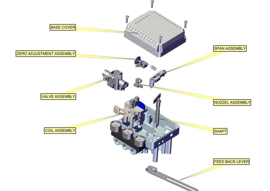
9 2.5. Part and assembly 2.6. RTX1000R RTX-IOM-RTX1000/1000L-R Page 9 of 26
10 2.7. RTX1000L RTX-IOM-RTX1000/1000L-R Page 10 of 26


11 2.8. Product dimension 2.9. RTX1000L RTX1000R RTX-IOM-RTX1000/1000L-R Page 11 of 26

12 3. Installation 3.1. Safety When installing a positioner, please ensure to read and follow safety instruction NOTE: Use bypass valve or other supportive equipment to avoid entire system shut down. WARNING: Any input or supply pressure to valve, actuator and / or to other related devices must be turned off Ensure there is no remaining pressure in the actuator RTX1000L Installation RTX 1000 L should be installed on linear motion valves such as globe or gate type which uses spring return type diaphragm or piston actuators. Before proceeding with the installation, ensure following components are available a. Positioner unit b. Feedback lever and lever spring c. Mounting bolts and washer 3.3. Installation steps Proper bracket must be made in order to adapt the positioner on the actuator. Please consider following important points when a bracket is being designed. NOTE: a. Positioner feedback lever must be parallel to the ground at 50% of valve stroke b. Feedback lever connection with the pin of the actuator clamp should be installed in such a way that the valve stroke length coincides with the corresponding figure in mm marked on feed back lever. Improper setting may cause poor linearity and may create unnecessary hunting during operation. RTX-IOM-RTX1000/1000L-R Page 12 of 26


13 Assemble the positioner with bracket made in previous step by fastening the bolts. Attach Positioner with bracket to the actuator yoke NOTE: Do not tighten Positioner completely Connect supply pressure to actuator temporarily. Supply enough supply pressure to the actuator in order to position the actuator clamp at 50% of the valve stroke. Insert connection pin into the feedback lever. The pin should be inserted when the actuator clamp is at 50% of the total valve stroke. Check if feedback lever is parallel to the ground at 50% of the valve stroke. If it is not parallel, adjust the bracket or feedback link bar to make parallel. Improper installation may cause poor linearity and may create unnecessary hunting during the operation. or both.. Check the valve stroke. The stroke marks are indicated on the feedback lever of the positioner. Position the connection pin at the number on the feedback lever which corresponds to the desired valve stroke. To adjust, move the bracket, the connection pin After installing the positioner, operate the valve from 0% to 100% stroke by using direct air to the actuator (manual position). On both 0% and 100%, the feedback lever should not touch the lever stopper, which is located on the backside of the positioner. If the feedback lever touches the stopper, the positioner should be installed further away from the yoke. RTX-IOM-RTX1000/1000L-R Page 13 of 26
.")
14 After the installation, tighten all of the bolts on the bracket, the feedback lever, and the connection pin RTX1000R Installation RTX 1000R can be used for rotary actuator as well as linear actuator (Cylinder). Rotary actuator motion valves are used for regulating ball valve, butterfly valve using rack and pinion, scotch yoke of complex type actuator, which its stem rotates 90 degrees. And linear actuators are used to regulate the motion of dampers, In this arrangement we use a profile plate which converts linear movement of cylinder into rotary motion. Be sure to check the following components before installation on rotary actuator. d. RTX main assembly e. IOM f. 1 Set of bracket (Not as a part of supply, needs to be order separately) g. 4 Socket set screw h. 4 Spring washer i. 4 Hexagon head bolt 3.5. Bracket information Standard bracket (included with the positioner) contains two components. The bracket can be used for NAMUR lever type. The bracket is designed to fit onto the actuator with 20mm stem height (H) Installation steps Please check the actuator s stem height Mount bracket onto the actuator. It is recommended to use spring washer so the bolts will not be loosen from vibration RTX-IOM-RTX1000/1000L-R Page 14 of 26

15 Set rotation position of the actuator stem at zero point, "0%." For a single type of actuator, it is easy to check zero point, because the actuator stem is positioned at zero point when there is no supply pressure. If double acting actuator is used, check actuator stem's rotation direction (clockwise or counter-clockwise) by supplying pressure. Tighten RTX 1000 base and the bracket with hexagon-headed bolts and plate washer. It is recommended to tighten four bolts after checking RTX 's position. RTX-IOM-RTX1000/1000L-R Page 15 of 26
16 4. Connections 4.1. Safety Supply pressure should be clean and dry air avoiding moisture, oil or dust. Always recommended to use air filter regulator (i.e. YT-200 series). ROTEX has not tested positioner operation with any gases other than clean air. Please contact ROTEX for any questions Supply Pressure Condition Dry air with at least 10 0 C lower than ambient temperature. Avoid from dusty air. Positioner inner filter can only filter 5 micron or larger. Avoid oil. Comply with ANSI/ISA (R1981) or ISA S (R1981). Supply pressure range is 1.4 ~ 7 kgf/cm2 ( kpa) Set air filter regulator s pressure level 10% higher than actuator s spring range pressure Piping Condition Ensure inside of pipe is clean of obstructions. Do not use pipeline that is squeezed or shows any type of damages. Pipeline should have more than 6mm of inner diameter (10mm outer diameter) to maintain flow rate. The length of pipeline system should not be extremely long. Longer pipeline system may affect flow rate due to the friction inside of the pipeline. RTX-IOM-RTX1000/1000L-R Page 16 of 26

17 4.4. Pipe Connection with actuator Single acting actuator RTX 1000R series single acting type is set to use OUT1 port. OUT1 port should be connected with supply pressure port from actuator when using single acting type of spring return actuator. Fig. 7 & Double acting actuator For RTX-1000R series double acting type, when inputting current signal, supply pressure is out from OUT1. RTX-IOM-RTX1000/1000L-R Page 17 of 26


18 5. Adjustment 5.1. Adjustment cam Direction of actuator's stem rotation must be checked when supply signal is supplied. When actuator's stem rotates clockwise, the face of cam must be shown "DA." On the other hand, when the stem rotates counter-clockwise, adjust cam so "RA" shows on the face of cam. Check whether actuator's angle is at the initial point. After checking the initial point, release the hexagonal flange nut and adjust the position of the bearing so it is at 0 point. Fig. 11 When produced, the cam is set as RA Adjustment Zero point Set supply signal at 3 psi and rotate adjuster clockwise or counter-clockwise to adjust actuator's rotation angle. Fig.12 When adjusting zero for single actuator, rotation angle is equal to positioner's pressure gauge. RTX-IOM-RTX1000/1000L-R Page 18 of 26

 A/M switch adjusts the valve operation to automatic or manual. When produced, RTX-1000 series is set at \"A(Automatic)\".")
19 5.3. Adjustment Span After setting zero, rotate Span screw so supply signal reaches at the span point on the indicator. Changing span point affects zero point setting. So zero setting must be set again. After setting zero point, confirm the span point. This step must be repeated until both points are properly set. For RTX 1000R with 1/2 split range, the span spring must be changed. After setting is completed, tighten Lock Screw Adjustment - A/M Switch (Auto/Manual) A/M switch adjusts the valve operation to automatic or manual. When produced, RTX-1000 series is set at "A(Automatic)". If user prefers the positioner setting as "M (Manual)," the setting can be changed by turning the switch counterclockwise. Fig. 14 If it is set as "M (Manual)", the air pressure will be supplied to the actuator directly. Always set back to "A (Automatic)" after setting change. If OUT2 in single acting actuator or double acting actuator is used, A/M Switch will not operate. Fig.14 RTX-IOM-RTX1000/1000L-R Page 19 of 26

20 5.5. Adjustment - Seat Adjuster Seat Adjuster is set according to the customer's request before the positioner is delivered. Please do not adjust the Seat Adjuster. Seat Adjuster is used for double acting actuator always. Please do not touch the Seat Adjuster, because it can affect the positioner's performance Adjustment Orifice If the size of actuator is too small relative to the flow rate, positioner can have hunting. In order to avoid hunting, orifice can be used. There are three types of the orifice. Actuator Size Orifice Size Suffix symbol 90cm² less Ø ~ 180cm² Ø cm² and above None 3 Remove the o-ring from OUT1 and OUT2 port and insert appropriate orifice. After inserting orifice, place back the o-ring. Make sure there is no substance entering into port. If hunting persists after inserting the orifice, please contact ROTEX or its appropriate agent. RTX-IOM-RTX1000/1000L-R Page 20 of 26


21 6. Maintenance Maintenance should be performed on pilot Valve Relay at least once a year. When dissembling the pilot valve relay, please do make sure not to lose o-ring or stabilizer spring. Pl. refer to Fig. 16 for the instruction. Remove stopper bolt. Unlock the Auto/manual Switch. Remove if there is any blocking within the port and orifice. RTX-IOM-RTX1000/1000L-R Page 21 of 26
22 7. Troubleshooting Positioner does not respond to the input signal. Check supply pressure level. The level must be at least 1.4 kgf/cm². Check if input signal is properly supplied to the positioner. The signal should be 4~20mA DC. Check if the positioner nozzle has been blocked. Also, check if the pressure is supplied to the positioner and the pressure is being exhausted through the nozzle. If the nozzle has been blocked by any substances, please send the product to ROTEX for repair. Check if feedback lever has been installed properly. Check if zero point or span point is properly set. Check if feedback lever has been installed properly. The pressure of OUT1 reaches exhausting pressure level and does not come back down. Check A/M Switch. If the switch has been damaged, replace the switch or pilot relayvalve. Check for a gap or damages between the nozzle and the flapper. If damaged, please send the product to ROTEX for repair. The pressure is exhausted only by A/M Switch. Check if the positioner nozzle has been blocked. Also, check if the pressure is supplied to the positioner and the pressure is being exhausted through the nozzle. If the nozzle has been blocked by any substances, please send the product to ROTEX for repair. Hunting occurs. Check if safety spring has been displaced. (Next to Pilot relay valve) Check if the size of actuator is too small. If so, insert an orifice in order to reduce the pressure flow rate. Check if there is any friction between the valve and the actuator. If so, increase actuator's size or reduce the friction level. Actuator only operates by On/Off. RTX-IOM-RTX1000/1000L-R Page 22 of 26
23 Check pipe connection. Check cam direction. Linearity is too low. Check if the feedback lever is properly installed. Especially check if the feedback lever is parallel to the ground at 50% point. Check if zero and span have been properly adjusted, that is not too low or not too high. Check if supply air pressure level is stable from the regulator. If the level is unstable, replace the regulator. Hysteresis is too low. In case of double acting actuator, check if seat adjustment has been properly done. Please contact ROTEX for any further inquiries regarding the seat adjustment. Backlash can occur when feedback lever and lever spring is loosen. To avoid backlash, adjust the lever spring. Check if the connection bar to the feedback lever is tightly fastened. RTX-IOM-RTX1000/1000L-R Page 23 of 26

24 8. Position transmitter calibration NOTE: Apply and maintain 24 V supply at the supply terminal. Ensure the polarity. Use proper height bush to maintain to maintain card contactless with the enclosure surface mountings. Handle with care, while fixing card on mounting. Keep hands clean and dry while handling the card. Keep switches at home position after calibration of card i.e. OFF. Enclosure should be enclosed with proper gasket and cables that are going inside the enclosure should be properly covered with cable glands. Use appropriate size of screw driver for card calibration and connectors. CAUTION: Don t touch the card components with bare hands. Don t handle the card with moist or dirty hands. Don t clean the card with hard brushes, if necessary use air blower. Details for PCB mounted Dinkle Connectors V Supply 2. - Ve supply (Gnd) 3. Potentiometer Connection :- If rotation of shaft is counter clockwise a. Variable Terminal 1 (1) b. Common 2 (2) c. Variable Terminal 2 (3) If rotation of shaft is clockwise a. Variable Terminal 3 (1) b. Common 2 (2) c. Variable Terminal 1 (3) RTX-IOM-RTX1000/1000L-R Page 24 of 26
 & SPAN (Open 100%) setting 1. Switch on DIP Switch 1(PROG Key) & Switch off DIP Switch 2. 2. Keep the actuator in closed condition; at this point 4mA output is needed.")
25 8.1. Calibration Potentiometer setting To set the potentiometer (10K) measure voltage between terminal shown J1 and ( ) terminal. For 4-20mA range, voltage range should be in between 0 to 2 Volts ZERO (Close 0%) & SPAN (Open 100%) setting 1. Switch on DIP Switch 1(PROG Key) & Switch off DIP Switch Keep the actuator in closed condition; at this point 4mA output is needed. 3. Set rotary switch at 0 (Arrow position at 0). 4. Press the Enter Key (Push Button) to set the value for 0 % or 4 ma. 5. Keep the actuator in open condition; at this point 20mA output is needed. 6. Set rotary switch at 0 (Arrow position at 0). 7. Switch on DIP SW 2 (20 ma). 8. Press the Enter Key (Push Button) to set the value for 100 % or 20 ma. 9. After setting the zero and span position as per above method, exit from the Program Mode by turning the PROG KEY & DIP SW 2 OFF. 10. Now card is set for 4-20 ma. RTX-IOM-RTX1000/1000L-R Page 25 of 26
26 9. Packaging & store 1. When not in use, Positioner should be kept in a sealed plastic bag in a cardboard box to prevent moisture or dust from contacting product. 2. Positioner should be stored in a dry place free from water and dust. 3. Store at temperature between 40 o F and 120 F (4 C and 49 C). 4. Locate in an area to avoid damage by impact. 10. Assistance For technical questions or assistance, contact any authorized distributor of ROTEX or: ROTEX MANUFACTURERS AND ENGINEERS PRIVATE LIMITED Manpada Road, Dombivli (East) Maharastra, INDIA. Tel: / / / Fax: aftersales@rotexautomation.com To find your local ROTEX representative: For more information about ROTEX and its network, Please visit RTX-IOM-RTX1000/1000L-R Page 26 of 26
Pneumatic Positioner RTX - Series USER S MANUAL. ROTEX P/P Ver. 0.1 Dated: MAY / 2009 REV 01: SEP/2010 Page 1 of 16
 Pneumatic Positioner RTX - Series USER S MANUAL MODEL RTX 1200 AMBIENT TEMP. 20 C ~ 70 C WEATHER PROOF IP 65 SUPPLY PR. 1.4 ~ 7.0 bar INPUT SIGNAL 0.2 ~ 1.0 bar SERIAL NO. ROTEX P/P Ver. 0.1 Dated MAY
Electro-Pneumatic Positioner RTX - Series USER S MANUAL. ROTEX E/P Ver. 0.1 Dated: dd / mm / yy Page 1 of 18
 Electro-Pneumatic Positioner RTX - Series USER S MANUAL ROTEX E/P Ver. 0.1 Dated dd / mm / yy Page 1 of 18-1 - RTX1000-R2-2011 Table of Contents Introduction 3 Manufacturer Warranty 3 General Service Information
Electro-Pneumatic Positioner YT-1000 / 1050 SERIES
 Electro-Pneumatic Positioner YT-1000 / 1050 SERIES PRODUCT MANUAL VERSION 1.01 Contents 1. Introduction 4 1.1 General information for the users. 4 1.2 Manufacturer Warranty 4 1.3 Explosion Proof Warning.
Pneumatic Positioner PNY Series USER'S MANUAL. Max-Air Technology. Version 1.0
 USER'S MANUAL Max-Air Technology Version 1.0 Table of Contents Introduction 3 Manufacturer Warranty 3 Product Description 4 Main Features and Functions 4 Operation Logic 4 Specification 5 Parts and Assembly
User s Manual. Pneumatic Positioner. Series 58. J Flow. Series 58. J Flow
 Pneumatic Positioner Series 58 User s Manual J Flow Series 58 J Flow Series 58 J Flow Controls, LLC 14 De Camp Cincinnati, OH 45216 Phone: 513-731-2900 Fax 513-731-6939 www.jflowcontrols.com Introduction
Electro-Pneumatic Positioner YT-1000 / 1050 SERIES
 Electro-Pneumatic Positioner YT-1000 / 1050 SERIES PRODUCT MANUAL VERSION 1.01 Contents 1. Introduction 4 1.1 General information for the users. 4 1.2 Manufacturer Warranty 4 1.3 Explosion Proof Warning.
SMART POSITIONER YT-2300 SERIES USER'S MANUAL
 SMART POSITIONER YT-2300 SERIES USER'S MANUAL Table of Contents Contents Page No. Introduction 4 Manufacturer Warranty 4 Product Description 5 Main Features and Functions 5 Label Description 6 Suffix Symbols
SMART POSITIONER YT-2400 SERIES USER'S MANUAL
 SMART POSITIONER YT-2400 SERIES USER'S MANUAL YTC V.1.02 1 Table of Contents Contents Page No. Introduction 4 Manufacturer Warranty 4 Product Description 5 Main Features and Functions 5 Label Description
Operation Manual Electro-Pneumatic Positioner Model: NT-1000R (Rotary Type) NUTORK CORPORATION
 NUTORK CORPORATION") Operation Manual Electro-Pneumatic Positioner Model: NT-1000R (Rotary Type) Integral Mounted Air Set Dome Indicator NUTORK CORPORATION Table of Contents Introduction 2 Manufacturer Warranty Product Description
Operation Manual Electro-Pneumatic Positioner Model: NT-1000R (Rotary Type) Integral Mounted Air Set Dome Indicator NUTORK CORPORATION Table of Contents Introduction 2 Manufacturer Warranty Product Description
BUS DOOR SYSTEM ELECTRO-PNEUMATIC IN-SWING BUS DOOR CONTROL MECHANISM
 BUS DOOR SYSTEM ELECTRO-PNEUMATIC IN-SWING BUS DOOR CONTROL MECHANISM Installation Operation and Maintenance Manual RTX-IOM-BDOS-R01-0216 Page 1 of 18 Table of Contents 1. Introduction... 3 1.1. Definitions...
Pneumatic cylinder CC Series (Ø200 Ø350)
") Pneumatic cylinder CC Series (Ø200 Ø350) Installation Operation and Maintenance Manual RTX-IOM-CC Series (Ø200 Ø350)-R01-0316 Page 1 of 22 Contents 1. Introduction... 3 1.1. Definitions... 4 2. Operation
Pneumatic cylinder CC Series (Ø200 Ø350) Installation Operation and Maintenance Manual RTX-IOM-CC Series (Ø200 Ø350)-R01-0316 Page 1 of 22 Contents 1. Introduction... 3 1.1. Definitions... 4 2. Operation
YT-1200 Series VERSION 1.02
 YT-1200 Series PRODUCT MANUAL VERSION 1.02 Contents 1. Introduction... 4 1.1 General Information for the users... 4 1.2 Manufacturer Warranty... 4 1.3 Explosion Proof Warning (Only for external explosion
Pneumatic cylinder SPC Series (Ø32 - Ø100)
") Pneumatic cylinder SPC Series (Ø32 - Ø100) Installation Operation and Maintenance Manual RTX-IOM-SPC Series (Ø32-Ø100)-R01-1215 Page 1 of 25 Contents 1. Introduction... 3 1.1. Definitions... 4 2. Operation
Pneumatic cylinder SPC Series (Ø32 - Ø100) Installation Operation and Maintenance Manual RTX-IOM-SPC Series (Ø32-Ø100)-R01-1215 Page 1 of 25 Contents 1. Introduction... 3 1.1. Definitions... 4 2. Operation
SMART POSITIONER YT-3400 SERIES
 SMART POSITIONER YT-3400 SERIES USER'S MANUAL 1 V.1.02 Table of Contents Introduction 4 Manufacturer Warranty 4 Product Description 5 Main Features and Functions 5 Label Description 6 Suffix Symbol 7 Specification
CONTROL VALVE ACCESSORIES CVA : 0611 ELECTRO PNEUMATIC / PNEUMATIC POSITIONER POSITION TRANSMITTER SIL
 ELECTRO PNEUMATIC / PNEUMATIC POSITIONER POSITION TRANSMITTER CVA : 0611 SIL Next generation of Positioner design featuring better performance and ease of setup has taken ELECTRO-PNEUMATIC POSITIONER RTX1000
Electro-Pneumatic Linear Positioner Installation and Operation Instructions B GB
 Installation and Operation Instructions 99.66.02-B GB Description of Device (4-~20mA) is the advanced control device for a linear control valve that provides unparalleled stability in difficult environments
SMART POSITIONER YT-3300/3301 SERIES
 SMART POSITIONER YT-3300/3301 SERIES PRODUCT MANUAL VERSION 1.02 Contents 1. Introduction 5 1.1 General information for the users. 5 1.2 Manufacturer Warranty 5 2. Product Description.. 6 2.1 General..
Pneumatic-Pneumatic Positioner YT-1200L,R Installation manual
 Installation Safety Warning When installing a positioned, please ensure to read and follow safety instruction. All input and supply pressure to valve, actuator, and other related devices must be turned
Installation and Operating Instructions Electro-Pneumatic Rotary Positioner SP-21. Description of Device. Part Number System
 Description of Device VALMAC Posi-Zest SP-2100 Series is the advanced control device for a rotary control valve that provides unparalleled stability in difficult environments. Easy Maintenance Precise
Smart Positioner YT-2400L,R Installation manual
 Installation Safety Warning When installing a positioner, please ensure to read and follow safety instruction. All input and supply pressure to valve, actuator, and other related devices must be turned
SP-20 Input. Installation and Operating Instructions Electro-Pneumatic Linear Positioner. Description of Device. Part Number System
 Description of Device VALMAC Posi-Zest SP-2000 Series is the advanced control device for a linear control valve that provides unparalleled stability in difficult environments. Easy maintenance Precise
SMART POSITIONER SS3400 SERIES
 SMART POSITIONER SS3400 SERIES PRODUCT MANUAL VERSION 1.03 Contents 1. Introduction 4 1.1 General information for the users. 4 1.2 Manufacturer Warranty 4 1.3 Explosion Proof Warning. 3 2. Product Description..
Moniteur INSTALLATION & OPERATING INSTRUCTIONS. SERIES 40 Positioners. Installation and Operating Instructions Series 40 Positioners.
 INSTALLATION & OPERATING INSTRUCTIONS SERIES 40 Positioners Form IO2-0406 Description of Device Moniteur's Series 40 pneumatic (3-15psi) and electropneumatic (4-20mA) positioners are advanced control devices
SMART POSITIONER YT-2500/2501/2550 SERIES
 SMART POSITIONER YT-2500/2501/2550 SERIES PRODUCT MANUAL VERSION 1.03 Contents 1. Introduction 5 1.1 General information for the users. 5 1.2 Manufacturer Warranty 5 2. Product Description.. 6 2.1 General..
YT-720 SERIES. Rotork YTC Limited VERSION 1.07
 YT-720 SERIES PRODUCT MANUAL YT-720S YT-720D Rotork YTC Limited VERSION 1.07 Contents 1. Introduction... 3 1.1 General Information for the users... 3 1.2 Manufacturer Warranty... 3 1.3 Explosion Proof
VOLUME BOOSTER RELAYS YT-310 / 315 SERIES
 VOLUME BOOSTER RELAYS YT-310 / 315 SERIES PRODUCT MANUAL VERSION 1.02 Contents 1. Introduction 3 1.1 General information for the users. 3 1.2 Manufacturer Warranty 3 2. Product Description.. 4 2.1 General..
AP ATEX AIRPOWER POSITIONERS AP2000 FEATURES AP1000 & AP1200 FEATURES OPTIONS OPTIONS
 AP1000-2000 Airpower positioners are a robust range of rotary or linear valve positioners in AP1000 electro-pneumatic (4-20mA), AP1200 pneumatic (3-15 psi) or AP2000 programmable smart type. Designed to
SMART POSITIONER 6000/6050 SERIES
 SMART POSITIONER 6000/6050 SERIES PRODUCT MANUAL VERSION 1.00 Contents 1. Introduction 5 1.1 General information for the users. 5 1.2 Manufacturer Warranty 5 2. Product Description.. 6 2.1 General.. 6
Installation- Linear. I & M Mark 17X Series. Mark 17X Linear Installation
 I & M Mark 17X Series 3170 Wasson Road Cincinnati, OH 45209 Phone 513.533.5600 Fax 513.871.0105 (f) info@richardsind.com www.jordanvalve.com Installation & Maintenance Instructions for the Mark 17X Series
Electro-Pneumatic Positioner Series 830/831-WP/EX. Operation & Maintenance Manual
 Electro-Pneumatic Positioner Series 830/831-WP/EX Operation & Maintenance Manual Electro-Pneumatic Positioner Model 830/831- WP/EXP This operation & maintenance manual corresponds to Forbes Marshall Arca
Series 60. New Smart Positioner. Compact design Convenient & powerful function Enhanced reliability
 Series 60 New Smart Positioner Compact design Convenient & powerful function Enhanced reliability J Flow Controls, LLC 14 De Camp Cincinnati, OH 45216 Phone: 513-731-2900 Fax 513-731-6939 www.jflowcontrols.com
YT-1000 / 1050 Series
 YT-1000 / 1050 Series PRODUCT MANUAL VERSION 1.07 Contents 1. Introduction... 5 1.1 General Information for the users... 5 1.2 Manufacturer Warranty... 5 1.3 Explosion Proof Warning (Only for explosion
SMART POSITIONER YT-2500 SERIES USER'S MANUAL
 SMART POSITIONER YT-2500 SERIES USER'S MANUAL YTC V.1.01 1 Table of Contents Introduction 4 Manufacturer Warranty 4 Product Description 5 Main Features and Functions 5 Label Description 6 Suffix Symbol
YT-200 / 205 / 220 / 225 Series YT-200 YT-205 YT-220 YT-225 VERSION 1.01
 YT-200 / 205 / 220 / 225 Series PRODUCT MANUAL YT-200 YT-205 YT-220 YT-225 VERSION 1.01 Contents 1. Introduction... 3 1.1 General Information for the users... 3 1.2 Manufacturer Warranty... 3 2. Product
INSTRUCTION MANUAL. CVS Series 3400 Flameproof Smart Positioner. Introduction
 INSTRUCTION MANUAL CVS Series 3400 Flameproof Smart Positioner Introduction The CVS 3400 is a CSA approved and Explosion Proof Rated EX d IIC T6/T5, Class 1, Zone 1, Group A. Additional certifications
POSITIONERS and Controls for Complete Valve Automation
 CONTROLS A Division of AT Controls Pneumatic & Electro-Pneumatic POSITIONERS and Controls for Complete Valve Automation 1 SS SERIES SS Features Easy and quick auto-calibration Detecting RA (reverse acting)
SMART POSITIONER YT-2500/2550 SERIES USER'S MANUAL
 SMART POSITIONER YT-2500/2550 SERIES USER'S MANUAL YTC 1 V.1.04 Table of Contents Introduction 4 Manufacturer Warranty 4 Product Description 5 Main Features and Functions 5 Label Description 6 Suffix Symbol
SMART POSITIONER YT-3400 / 3450 SERIES PRODUCT MANUAL
 SMART POSITIONER YT-3400 / 3450 SERIES PRODUCT MANUAL VERSION 1.03 Contents 1. Introduction 4 1.1 General information for the users. 4 1.2 Manufacturer Warranty 4 1.3 Explosion Proof Warning. 3 2. Product
SS3 Linear / Rotary. Smart Valve Positioner. Smart performance with innovative and ever-strong coil drive even under harsh working environments
 Smart Valve Positioner SS3 Linear / Rotary Smart performance with innovative and ever-strong coil drive even under harsh working environments Easy and quick auto-calibration Detecting RA (reverse acting)
Series 185/285 Smart Positioners
 Series 185/285 Smart Positioners Bulletin V-185/285 Specifications - Installation and Operating Instructions DOUBLE ACTION SINGLE ACTION LCD SCREEN SMART POSITIONER 3-47/64 [95.00] Series 185 3-27/32 [97.50]
Type Installation, Operation and Maintenance Instructions. Ordering Information. Contents CA20 -
 Type 2000 Pneumatic and Electropneumatic Valve Positioner Installation, Operation and Maintenance Instructions Ordering Information Use this coding system to order Model CA20 - Type of Positioner 00 P/P
CVS 2400 SERIES SMART POSITIONER
 CVS 2400 SERIES SMART POSITIONER Product Manual PRODUCT DRIPTION YT-2400 Smart Valve Positioner accurately controls valve stroke according to input signal of 4~20mA input from a controller. In addition,
Instruction and Operating Manual
 Instruction and Operating Manual Electro-Pneumatic Positioner Power-Genex Ltd. Contents 1. Safety Instructions / Precautions 2 2. Description 7 3. Description 7 4. Specifications 8 5. Part Numbering System
V200 Series Positioners
 V200 Series Positioners In a single compact and rugged housing The V200 positioner incorporates the flexibility of converting from a pneumatic unit to several versions of an electropneumatic unit, and
Fig Single-Acting Rotary Smart Positioner
 Fig. 3303 Single-Acting Rotary Smart Positioner Order Information Model No. EC03303RSN52000S Econ series 3300 Smart Positioner for quarter turn actuators in single acting version. This positioner regulates
YT-520S YT-520D YT-525S YT-525D YT-530S YT-530D YT-535S YT-535D
 YT-520 / 525 / 530 / 535 Series PRODUCT MANUAL YT-520S YT-520D YT-525S YT-525D YT-530S YT-530D YT-535S YT-535D VERSION 1.04 Rotork YTC Limited Contents 1 Introduction...3 1.1 General Information for the
VALVE ACCESSORIES & CONTROLS V200 POSITIONER A POSITIONER THAT OFFERS IT ALL IN ONE COMPACT, SIMPLE, HOUSING
 VALVE ACCESSORIES & CONTROLS V200 POSITIONER A POSITIONER THAT OFFERS IT ALL IN ONE COMPACT, SIMPLE, HOUSING WWW.VACACCESSORIES.COM 205-678-0507 The V200 Positioner Internal I/p with simple loop test points.
TOP-QUALITY PNEUMATIC ACTUATOR
 TOP-QUALITY PNEUMATIC ACTUATOR BS EN ISO 9001:2000 INTRODUCTION PDS series Pneumatic Actuators are designed using Scotch-Yoke technology from PDS 50 to the largest of PDS 200. Scotch-Yoke technology is
V200 Series Positioners
 V200 Series Positioners In a single compact and rugged housing The V200 incorporates the flexibility of converting from a pneumatic unit to several versions of an electropneumatic unit, and the ability
V200 Series Positioners
 V200 Series Positioners In a single compact and rugged housing The V200 positioner incorporates the flexibility of converting from a pneumatic unit to several versions of an electropneumatic unit, and
EB EN. Type 3372 Electropneumatic Actuator. Translation of original instructions
 EB 8313-1 EN Translation of original instructions V2001-IP Control Valve Type 3372 0511/0531 Electropneumatic Actuator with Type 3321 Valve Type 3372 Electropneumatic Actuator Edition July 2013 Note on
YT-2600 SERIES VERSION 1.07
 SMART POSITIONER YT-2600 SERIES PRODUCT MANUAL VERSION 1.07 Contents 1. Introduction... 4 1.1 General Information for the users... 4 1.2 Manufacturer Warranty... 4 1.3 Explosion Proof Warning & Specific
YT-2500 / 2550 / 2501 SERIES
 SMART POSITIONER YT-2500 / 2550 / 2501 SERIES PRODUCT MANUAL VERSION 1.10 Contents 1. Introduction... 5 1.1 General Information for the users... 5 1.2 Manufacturer Warranty... 5 1.3 Explosion Proof Warning
Powers Controls RL 147 Positioning Relay
 Powers Controls Technical Instructions Document No. 155-038P25 RL 147-2 Description Features Rapid response Product Numbers See Table 1. The is a compact, pneumatic device designed to provide positive
SS2 Linear / Rotary Smart Valve Positioner
 COTROLS A Division of AT Controls Smart performance with innovative and ever-strong coil drive even under harsh working environments Also available in REMOTE TYPE 316 STAILESS STEEL BODY Smart performance
SMART VALVE POSITIONER 4 to 20 ma + HART Digital Communication. smar B87
 SMART VALVE POSITIONER to ma + HART Digital Communication B87 DESCRIPTION The FY microprocessor based positioner provides fast and accurate positioning of diaphragm or cylinder actuators. The FY produces
PMV P36C AND P41C POSITIONERS ACTUATORS
 PMV P36C AND P41C POSITIONERS USED WITH DeZURIK PNEUMATIC ACTUATORS Instruction D10327 August 2012 Instructions These instructions provide information about Models P36C and P41C PMV Positioners. They are
V200 POSITIONER. Datasheet
 atasheet 1 CONTENTS 1 INTOUCTION... 3 1.1 Principle of Operation... 3 1.2 Product Identification... 3 1.3 Air quality recommendations... 4 1.4 Safety Instructions... 4 2 INSTALLATION... 5 2.1 Connections...
CENTAC Inlet and Bypass Valve Positioners
 CENTAC Inlet and Bypass Valve Positioners INGERSOLL-RAND AIR COMPRESSORS INLET AND BYPASS VALVE POSITIONERS Copyright Notice Copyright 1992, 1999 Ingersoll-Rand Company THIS CONTENTS OF THIS MANUAL ARE
Operating Instructions. Pneumatic Control Valve Low Temperature. Type Series GS3
 Operating Instructions Pneumatic Control Valve Low Temperature Type 8026 Series GS3 With: Digital Positioner Type 8048 Electro-pneumatic Positioner Type 8047 Pneumatic Positioner Type 8047 Version: 03/2006
Type Type 1001 Transducers. I/P & E/P Transducers
 Type 1001 I/P & E/P Description The Type 1001 is a patented family of electropneumatic instruments that is used to reduce a supply pressure to a regulated output pressure which is directly proportional
Operating Instructions. Angle Seat Control Valve. Type 7020
 Operating Instructions Angle Seat Control Valve Type 7020 With: Digital Positioner Type 8048 Electro-pneumatic Positioner Type 8047 Pneumatic Positioner Type 8047 Version: 02/2006 Manual-7020e.doc Art.-No:
Instruction and Operating Manual
 M/SS2/E 01 2011 Instruction and Operating Manual Smart Valve Positioner SS2L / SS2R Series Contents 1. Introduction 2 11.5 Sub-Parameters Flow Diagram 2. Overview of Structure 3 11.5.1 Change of Input
Pneumatic or Electropneumatic Positioner for Rotary Actuators Type Fig. 1 Type 3761 Positioner. Mounting and Operating Instructions EB 8386 EN
 Pneumatic or Electropneumatic Positioner for Rotary Actuators Type 3761 Fig. 1 Type 3761 Positioner Mounting and Operating Instructions EB 8386 EN Edition June 2004 Contents Contents Page 1 Design and
Corrosion Resistant Pneumatic Positioners Model 4700P and 4700E
 Corrosion Resistant Pneumatic Positioners Specification Data CS2007 4/98 Table of Contents Foreword............................................................. 2 Numbering System.....................................................
K10 Intrinsically Safe Electro-Pneumatic Positioner Operating Manual
 K0 Intrinsically Safe Electro-Pneumatic Positioner Operating Manual Pneumatic Connection Outlet Port Gauge Single Acting Actuator (Spring Return): For single acting actuators Outlet Port 2 is to be plugged.
Type 2000 Transducer Product Instructions
 Type 2000 Transducer Product Instructions The Type 2000 is an electro-pneumatic device that regulates an unregulated supply pressure down to an electronically-controlled output pressure. There are two
TMP-3000 VERSION 1.01
 VERSION 1.01 Contents 1. Introduction... 4 1.1 General Information for the users... 4 1.2 Safety precautions and Manufacturer Warranty... 4 2. Product Description... 5 2.1 General... 5 2.2 Main Features
Features. Flexibility
 The V100 positioner can be ordered as a base model pneumatic positioner, converted to standard NEMA 4X electropneumatic, EX model, or FF (fail freeze) model in a matter of minutes, without removing the
PRODUCTS CATALOG (2018) TISSIN CO.,LTD. Smart Valve Positioner. Electro-Pneumatic Positioner. Volume Booster. Lock Up Valve. Air Filter Regulator
 TISSIN CO.,LTD. Smart Valve Positioner. Electro-Pneumatic Positioner. Volume Booster. Lock Up Valve. Air Filter Regulator") PRODUCTS CATAOG (08) TISSIN CO.,TD. Smart Valve Positioner Electro-Pneumatic Positioner Volume Booster ock Up Valve Air Filter Regulator Solutions for control valve system About Tissin Solutions for control
PRODUCTS CATAOG (08) TISSIN CO.,TD. Smart Valve Positioner Electro-Pneumatic Positioner Volume Booster ock Up Valve Air Filter Regulator Solutions for control valve system About Tissin Solutions for control
Solenoid Valves Type 3963
 Mounting and Operating Instructions Solenoid Valves Type 3963 Fig. 1 General Assembly, commissioning and operation of these devices may only be performed by experienced personnel. Proper shipping and appropriate
Mounting and operating instructions EB 5801 EN. Electric Actuators Type 5801 (Rotary Actuator) Type 5802 (Linear Actuator)
 Type 5802 (Linear Actuator)") Electric Actuators Type 5801 (Rotary Actuator) Type 5802 (Linear Actuator) Linear Actuator with Type 3260 Control Valve Rotary actuator with lever system Linear actuator with Type 3321 (V2001) Control
Electric Actuators Type 5801 (Rotary Actuator) Type 5802 (Linear Actuator) Linear Actuator with Type 3260 Control Valve Rotary actuator with lever system Linear actuator with Type 3321 (V2001) Control
V100 Positioner CONTENTS
 CONTENTS 1 INTRODUCTION... 2 1.1 General... 2 1.2 Function... 2 1.3 Product Identification... 3 1.4 Air quality recommendations... 3 1.5 Safety Instructions... 4 2 INSTALLATION... 5 2.1 Connections...
Series 3730 Electropneumatic Positioner Type
 Series 3730 Electropneumatic Positioner Type 3730-1 Application Single-acting or double-acting positioner for attachment to pneumatic control valves. Self-calibrating, automatic adaptation to valve and
XL90 Series High-Performance Positioner
 XL90 Series High-Performance Positioner GENERAL INFORMATION This bulletin is designed to assist in installing, calibrating, troubleshooting and performing maintenance as required for the XL90 Series high-performance
XL90 Series High-Performance Positioner
 Flowserve Corporation 765 South 100 East Phone: 801 373 3028 Flow Control Division Provo, Utah 84606 Facsimile: 801 489 2228 Automation Business Unit www.flowserve.com Email: actuators@flowserve.com XL90
ECON Limit Switch Box Fig
 ECON Limit Switch Box Fig. 79651 Scan for manual Installation & Operation Manual for Limit Switch Box: Fig. 79651 Rev.4 1 Contents Page 1. INTRODUCTION 3 2. SWITCH BOX SPECIFICATION 3 3. SWITCH TYPE SELECTION
Operation and Maintenance Instructions Manual BOOSTER. Volume amplifier
 Operation and Maintenance Instructions Manual BOOSTER Volume amplifier 1. GENERAL INFORMATION... 3 2. TECHNICAL SPECIFICATIONS... 3 3. DIMENSIONAL DESIGN... 4 3.1 BOOSTER WITHOUT SIGNAL ADAPTER... 4 3.2
The EP5 electropneumatic positioner is
 EP5 Electropneumatic Positioner The EP5 electropneumatic positioner is adapted from the PMV P5 pneumatic positioner. This compact and sturdy unit is designed for maximum performance in all types of environments.
Type 3761 Pneumatic or Electropneumatic Positioner for Rotary Actuators. Fig. 1 Type 3761 Positioner. Mounting and Operating Instructions EB 8386 EN
 Type 3761 Pneumatic or Electropneumatic Positioner for Rotary Actuators Fig. 1 Type 3761 Positioner Mounting and Operating Instructions EB 8386 EN Edition July 2007 Contents Contents Page 1 Design and
 Flow Line Controls Positioner Specifications Series 55 3-15 psi Pneumatic Series 56 4-20 ma Electro-Pneumatic Series 55 Series 56 Flow Line Controls, Inc. P.O. Box 677 Schriever, LA 70395 Phone: 985-414-6003
Valve Positioners Series 760P/E Valve Positioners
 Introduction Features & Benefits Universal design and choice of interchangeable AMUR IEC 54-6 rectilinear or VDI/VDE 845 rotary mountings provide wide application flexibility Double-acting or single-acting
DeZURIK P200-P204 POSITIONERS. With Feedback and External Options
 DeZURIK P200-P204 POSITIONERS With Feedback and External Options Instruction D10471 February 2016 DeZURIK VAC P200-P204 Positioners with Feedback and External Options Instructions These instructions provide
T-1001 TYPE 1001 I/P & E/P TRANSDUCERS
 TYPE 1001 I/P & E/P TRANSDUCERS T-1001 The Type 1001 is a patented family of electro-pneumatic instruments that is used to reduce a supply pressure to a regulated output pressure which is directly proportional
Installation & Operation Manual
 Installation & Operation Manual (I-TORK PDS Series Pneumatic Actuator) PDS-M0108/1010 74-6, Chun Ui-Dong, Won Mi-Gu, Bucheon, Kyoung Ki-Do, Korea Tel : 82-2-855-1365, 66 Fax : 82-2-855-1367 E-mail : roy75@i-tork.com
2-Way & 3-Way Non Spring Return Characterized Ball Valves
 VCB30 Series Revision Date June 6, 2014 2-Way & 3-Way Non Spring Return Characterized Ball Valves General The VCB30 Series electric rotary-motion actuatordriven characterized ball valves are designed specifically
Spring Cylinder Rotary Actuator
 Spring Cylinder Rotary Actuator Rotary Actuator Spring Cylinder Rotary Actuators High torque and pneumatic stiffness combine together in the Mascot "Spring cylinder rotary actuator" These characteristics
Actuators & Positioners Characterizable Pneumatic Positioners Series AV1/2/3
 Data Sheet Actuators & Positioners Characterizable Pneumatic Positioners Series AV1/2/3 Proven pilot valve - Increased realiability minimizes downtime and maintenance costs. High capacity - Standard model
4.3 MSK SWITCH BOX MSK (SIZE I) FEATURES ADVANTAGES
 FEATURES ADVANTAGES") SWITCH BOX MSK (SIZE I) FEATURES - A compact, robust switch box to be mounted on pneumatic actuators - Position response via integrated micro limit switches - Integrated terminal Strip - The micro limit
SWITCH BOX MSK (SIZE I) FEATURES - A compact, robust switch box to be mounted on pneumatic actuators - Position response via integrated micro limit switches - Integrated terminal Strip - The micro limit
ABB MEASUREMENT & ANALYTICS DATA SHEET. AV1 and AV2 Characterizable pneumatic and electro-pneumatic positioners
 ABB MEASUREMENT & ANALYTICS DATA SHEET AV1 and AV2 Characterizable pneumatic and electro-pneumatic positioners 2 AV 1 AN D AV 2 CH AR ACTER I Z ABLE PNE U MATIC POSITIONE RS DS/AV 1 2-E N RE V. I Measurement
Damper Actuator Installation
 FANs 268.1, 977, 1628.3 Installation Bulletin EPP-1000 Issue Date 0800 EPP-1000 Series Electro-Pneumatic Positioners A pplication The EPP-1000 is designed for applications where electronic control of pneumatic
Control Valves Positioner
 Control Valves Positioner HiFlo Valve Positioner Easy calibration Corrosion-resistant cover and base Withstands 150 psi at all parts Two -sided cam for easy field reversibility Optional / NPT for piped
Control Valves Positioner
 Control Valves Positioner HiFlo HiFlo Valve Positioner Corrosion-resistant cover and base Easy calibration Withstands 150 psi at all parts Two -sided cam for easy field reversibility Optional / NPT for
VA-908x Series Electric Rotary Actuators for Two-Position and Modulating Service
 VA-908x Series Electric Rotary Actuators for Two-Position and Modulating Service Installation Instructions VA-908x Code No. LIT-12011566 Issued August 24, 2009 Applications The VA-908x Series Electric
YT-3300 / 3350 / 3303 / 3301 SERIES
 SMART POSITIONER YT-3300 / 3350 / 3303 / 3301 SERIES PRODUCT MANUAL YT-3300 YT-3300 with limit switch YT-3350 YT-3303 YT-3303 YT-3301 VERSION 1.11 Contents 1. Introduction... 5 1.1 General Information
Easytork Solenoid Valve IOM
 Easytork Solenoid Valve IOM General This installation document is to be read in conjunction with the Easytork Vane Actuator IOM. Description The Easytork Solenoid Valve ( ESV ) series is intended for the
ELECTRONIC CONTROL ACTUATOR
 ELECTRONIC CONTROL ACTUATOR Nucom Series LINEAR TYPE Nucom L100 OPERATION MANUAL Koei Industry Co., Ltd. FOR YOUR SAFETY In order for better and safety use of the product for a long period, please observe
OM Field-Type I/P Converter Model : KUX113 User's Manual
 OM2-5900-1130 Field-Type I/P Converter Model : KUX113 User's Manual Copyright, Notices and Trademarks 1994-2012 Azbil Corporation All Rights Reserved. While this information is presented in good faith
Electropneumatic Converters i/p Converters Type 6111 Mounting and Operating Instructions EB 6111 EN
 Electropneumatic Converters i/p Converters Type 6111 Fig. 1 Type 6111 in standard version Fig. Type 6111 mounted on a supply air manifold Fig. 3 Type 6111 in field enclosure Mounting and Operating Instructions
OPERATING INSTRUCTIONS PLEASE READ CAREFULLY
 OPERATING INSTRUCTIONS PLEASE READ CAREFULLY 925-0330 Rev 0 0416 TABLE OF CONTENTS SAFETY SUMMARY... 3 SPECIFICATIONS... 4 1.0 INTRODUCTION/DESCRIPTION.... 5 2.0 LOCATION AND MOUNTING... 5 3.0 CONNECTIONS