D691 Series PQ Servo-Proportional Valves with Integrated Electronics
|
|
|
- Norah Hampton
- 6 years ago
- Views:
Transcription
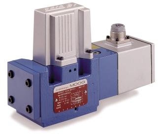
1 D691 Series PQ Servo-Proportional Valves with Integrated Electronics
 control.")

2 SERVO-PROPORTIONL CONTROL VLVES PQ VERSION TWO STGE WITH D691 SERIES SERVO-PROPORTIONL VLVES The D691 servo-proportional control PQ-Valves are dual function valves for 2x2-, 3-, 4- and 5-way applications. The PQ-Valves modulate a fluid flow and control closed loop pressure (upper or lower pressure limit) control.the valves are suitable for pressure control and pressure limiting applications. The control electronics for the spool position transducer, pressure loops and pressure transducer are integrated in the valve. Moog created the first closed loop PQ valve nearly 15 years ago. Since then, Moog has produced more than 30,000 PQ-Valves. pplications include injection molding, heavy industry, presses and paper processing.the valves have proved to be extremely reliable, especially when high dynamic performance is required. Over the years, Moog has made steady improvements to its basic PQ design. Our new ServoJet pilot is a new innovation that results in increased energy savings and robustness. The pilot stage uses the jet pipe principle which for over 8 years has been operating reliably in different Moog valves. The integrated valve electronics require either a 24 Volt DC or a ±15 Volt DC power supply. The valve series described in this catalog has successfully passed EMC tests required by the EC Directive. Please take notice of the references in the electronics section. VLVE FETURES Improved flow recovery (> 90% of the pilot stage internal leakage flow) contributes to energy savings, especially for machines with multiple valves. Improved dynamics due to high natural frequency (500 Hz) of the ServoJet pilot stage. Reliable operation.the high pressure recovery of the ServoJet stage (more than 80% p at 100% command signal) provides higher spool driving forces and ensures enhanced spool position repeatability. Operational with only 215 psi pilot pressure. llows for proportional control in low pressure systems such as turbine controls. The pilot stage filter has almost unlimited life due to the 200 µm nominal fineness. Improved frequency response allows high spool position loop gain. The high loop gain provides excellent static and dynamic response, resulting in superior control system performance. Fail-safe versions with defined spool position using a spring, a poppet valve or by external supply cutoff. 2-stage Proportional PQ-Valve D691 Series X T P T2 Y Our Quality Management System is certified in accordance with DIN EN ISO This catalog is for users with technical knowledge.to ensure that all necessary characteristics for function and safety of the system are given, the user has to check the suitability of the products described here. In case of doubt, please contact Moog. 2
3 OPERTION FLOW RTE MODE n electrical command signal (flow rate set point) is applied to the integrated position controller which drives the valve coil.the position transducer (LVDT), which is excited via an oscillator, measures the position of the spool (actual value, position voltage). This signal is then demodulated and fed back to the controller where it is compared with the command signal.the controller drives the pilot valve until the error between command signal and feedback signal is zero. Thus the position of the spool is proportional to the electrical command signal. FLOW RTE ND PRESSURE DROP The actual flow is dependent upon electrical command signal and valve pressure drop.the flow for a given valve pressure drop can be calculated using the square root function for sharp edged orifices as follows: Q = QN p pn Q [gpm] = calculated flow QN [gpm] = rated flow p [psi] = actual valve pressure drop pn [psi] = rated valve pressure drop Flow Rate Command Pressure Limiting Controller Limiting Pressure Command Spool Position Command ctual Position p + - ctual Pressure Position Controller X u X Coil Current Valve Position Transducer Pressure Transducer Flow Spool Position Load Load Pressure Velocity PRESSURE CONTROL MODE The aforementioned flow rate control is superimposed with pressure limiting control. oth command signals (external flow command signal and limiting pressure command signal) must always be present. The difference between external flow command signal and output signal of the pressure limiting controller, results in a spool position command signal. This output signal is zero as long as the actual pressure is smaller than the limiting pressure command value. If the actual pressure value exceeds the limiting pressure command value, the pressure limiting controller reduces the spool position command signal until the actual pressure value equals the limiting pressure command value. If pressure control has to be installed (instead of pressure limiting), the external flow command signal must be selected high so that the limiting function actually occurs. This is necessary because the pressure limiting controller can only reduce the spool position command.the external flow command signal should be larger than 30% of rated signal (see diagrams on page 4). EXTERNL PILOT PRESSURE If large flow rates with high valve pressure drop are required an appropriate higher pilot pressure has to be chosen to overcome the flow forces. n approximate value can be calculated as follows: Q PX p K Q [gpm] = max. flow p [ psi] = valve pressure drop with Q K [in 2 ] = spool drive area PX [psi] = pilot pressure The pilot pressure px has to be at least 215 psi above the return pressure of the pilot stage. 3
4 TYPICL CHRCTERISTIC CURVES FLOW ND PRESSURE RESPONSE FLOW STEP RESPONSE FREQUENCY RESPONSE (FLOW) FLOW VS. SIGNL CURVE Stroke [%] ,000 psi 2,000 psi 1,000 psi Time [ms] mplitude Ratio [d] ±90% ±25% ±10% Frequency [Hz] Phase Lag [degrees] Flow [gpm] Signal for main line appl. [%] Signal for by-pass line appl. [%] U T Q N[gpm] Frequency response data measured at 2,000 psi pilot pressure, fluid viscosity of 32 mm 2 /s, and fluid temperature of 104 F. at pn = 150 psi Spool : ~critical lap, linear characteristic Spool U: ~critical lap, curvilinear characteristic (5-way only) Spool T: ~20% overlap, linear characteristic PRESSURE STEP RESPONSE Pressure p [psi] 0 1,000 2,000 3,000 Pressure p [psi] 0 1,000 2,000 3,000 80% 25% 10% 10/25% 80% Examples for pressure step response show the effect of valve flow setting and entrapped fluid volume on pressure control dynamics.valve type D Q30 K... with optimized PID pressure limiting controller at operating pressure pp = 3,570 psi Time [ms] Time [ms] Optimized and measured with entrapped fluid volume of 61 in 3. Valve flow command 80% of rated. Optimized and measured with entrapped fluid volume of 61 in 3. Valve flow command 10 / 25 / 80% of rated. Pressure p [psi] 0 1,000 2,000 3,000 Pressure p [psi] 0 1,000 2,000 3, Time [ms] Optimized for entrapped fluid volume of 61 in 3 but measured with 305 in 3. Valve flow command 80% of rated Time [ms] Optimized and measured with entrapped fluid volume of 305 in 3. Valve flow command 80% of rated. Note: It is necessary to adapt the valve p- electronics to the load conditions for any new application. If required please contact MOOG for assistance.
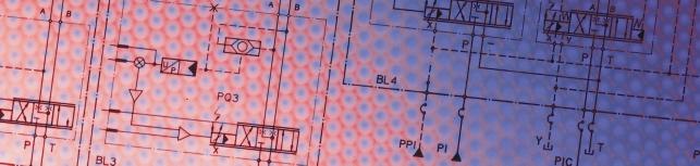
5 PPLICTION NOTES 3-way valve in main line 5-way valve in main line 4-way valve in main line 2x2-way valve in by-pass line (bleed off) X Y P T, T2 X Y P, P 2 T X Y P T, T2 X Y P, T, T2 P T optional: X and Y external only with X and Y external P and T ports interchanged, not conforming to ISO 4401 optional:y external optional: Y external The device operates as a 3-way pressure reducing valve with flow from P or T. Only one load port () is used. VENTING OF THE PRESSURE TRNSDUCER efore operating the valve, the internal lines of the pressure transducer must be carefully vented.when selecting the installation position of the valve, care must be taken so that the bleeding screw is effective. In other words, if the load is located higher than the PQ-Valve, the load must be vented at its highest point, which would not be at the valve. Caution:Vent only at reduced pressure! Danger of injury! The device operates like the 3-way PQ-Valve but with doubled flow rate into the load. directional change of the load motion requires an external force. Without shuttle valve The device operates from P like a 3-way PQ-Valve. In the opposite direction, P, it allows only flow modulation. This means the direction of load motion can be reversed (open loop velocity control for load retract). With shuttle valve The device operates as an electrically adjustable 4-way throttle valve, i. e. the load can be operated with pressure control in both directions of motion. Only one of the load ports is pressure controlled.the shuttle valve transmits the driving (higher) load pressure to the single pressure transducer. n electronic logic circuit provides for the coordination of motion direction and pressure control depending on the polarity of the flow rate command signal. The other port is more or less open to tank line which is provided by the special spool land location.the spring centered fail-safe version requires external pilot supply port X to be used. The device has parallel flow paths and operates as an electrically adjustable pressure relief valve from T and T2, respectively. t zero command signal the valve is fully open, i. e. the pressure in the load ports is zero apart from minor pressure build up due to line losses. minimum pilot pressure (px > 215 psi) has to be secured.this can be achieved by a check valve with 215 psi cracking pressure (as shown) or by a separate pilot supply pump. 5
6 VLVE ELECTRONICS WITH SUPPLY VOLTGE 24 VOLT COMMND SIGNL FOR FLOW Q Voltage command 0 to ±10 V The spool stroke of the valve is proportional to (U4 U2). 100% valve opening P and T is achieved at +10 V input signal. t 0 V command the spool is in a centered position. Current command 0 to ±10 m (4 to 20 m resp.) The spool stroke of the valve is proportional to I4 (I4-12 m resp.). 100% valve opening P and T is achieved at +10 m (20 m resp.) input signal. t 0 m (12 m resp.) command the spool is in a centered position. Command signal for pressure p Voltage command 0 to +10 V The controlled load pressure is proportional to (U9 U2). 100% rated pressure is achieved at +10 V input signal. Current command 0 to +10 m (4 to 20 m resp.) The controlled load pressure is proportional to I9. 100% rated pressure is achieved at +10 m (20 m resp.) input signal. CTUL VLUE SPOOL POSITION Q Valves with voltage and current command input The actual value, i.e. the spool position, can be measured between pins 6 and 7.This signal can be used for monitoring and fault detection purposes. The signal must be measured with a voltmeter having an input impedance greater than 1 MΩ (diagram below, left).the spool stroke range corresponds to ±10 V.The centered position is at 0 V. +10 V corresponds to 100% valve opening P. If the actual value shall be used with a machine control system, the differential input circuit must be applied (diagram below, right). ctual value pressure p Signal levels for actual pressure output (U10 U2 and I10 resp.) are given in the wiring table below. Note: When the p-potentiometer is readjusted with reference to a manometer this output will not change. GENERL REQUIREMENTS Supply 24 VDC, min.19 VDC, max. 32 VDC. Current consumption max. 300 m ll signal lines, also those of external transducers, shielded Shielding connected radially to (0 V), power supply side, and connected to the mating connector housing (EMC) EMC: Meets the requirements of EN 55011/03.91 class, EN /01.92, and EN /03.95, performance criteria class Protective grounding lead.75 mm 2 Note:When making electrical connections to the valve (shield, protective grounding) appropriate measures must be taken to ensure that locally different earth potentials do not result in excessive ground currents. See also Moog pplication Note M 353 E. Circuit diagram for measurement of actual value U6-7 (spool position) 4 k k 7 6 Valve Connector U6-7 V = Input Resistance > 1 MΩ Measurement between pin 6 and signal ground results in an actual value of 2.5 to 13.5 V. 4 k k 7 6 Valve Connector 15 k 4 k k 20 k + - V = U6-7 CONNECTOR WIRING Valve with 11+PE pole connector to DIN and mating connector (metal shell) with leading protective earth connection Valve Connector 11 Mating Connector Cabinet Side PE Function Supply Supply / Signal Ground Enabled Not Enabled Input Rated Command Q Not Used Output ctual Value Q (Differential) Enabled and Supply cknowledged Input Rated Command p Output ctual Value p* Position Error, Logic Protective Earth Voltage Command Input Resistance 50 kω Input Resistance = 50 kω Output Resistance = 10 kω (0 V) 0 ±10 m Load Resistance = 500 Ω Current Command 24 VDC (min. 19 VDC, max. 32 VDC) U8-2 > +8.5 VDC U3-2 < +6.5 VDC I = 1.2 m at 24 VDC U8-2 > +8.5 VDC = o.k. U3-2 < +6.5 VDC = not o.k. V8-2 > +8.5 VDC: < 30% V3-2 < +6.5 VDC: > 30% 0 ±10 m Load Resistance 500 Ω 0 ±10 V Ra: approx. 20 kω 0 ±10 m Load Resistance Max. = 1 kω m Load Resistance 250 Ω Output Imax : 20 m m Load Resistance 250 Ω +4 to +20 m Load Resistance Max. 500 Ω Output Imax : 20 m 6 * not affected by p-potentiometer (pages 8 and 9)
7 VLVE ELECTRONICS WITH SUPPLY VOLTGE ±15 VOLT COMMND SIGNL FOR FLOW Q Voltage command 0 to ±10 V The spool stroke of the valve is proportional to (U4 U3). 100% valve opening P and T is achieved at +10 V input signal.t 0 V command the spool is in a centered position. Current command 0 to ±10 m (4 to 20 m resp.) The spool stroke of the valve is proportional to I4 (I4 12 m resp.). 100% valve opening P and T is achieved at +10 m (20 m resp.) input signal. t 0 m (12 m resp.) command the spool is in a centered position. COMMND SIGNL FOR PRESSURE P Voltage command 0 to +10 V The controlled load pressure is proportional to (U9 U3). 100% rated pressure is achieved at +10V input signal. Current command 0 to +10 m (4 to 20 m resp.) The controlled load pressure is proportional to I9. 100% rated pressure is achieved at +10 m (20 m resp.) input signal. ctual value spool position (Q) Signal levels for actual flow output (U6 U3 and I6 resp.) are given in the wiring table below. GENERL REQUIREMENTS ctual value pressure p Signal levels for actual pressure output (U10 U3 and I10 resp.) are given in the wiring table below. Note:When the p- potentiometer is readjusted with reference to a manometer, this output will not change. Supply ±15 VDC. ±3%. Current consumption max. ±300 m ll signal lines, also those of external transducers, shielded Shielding connected radially to (0 V), power supply side and connected to the mating connector housing (EMC) EMC: Meets the requirements of EN 55011/03.91 class, EN /01.92 and EN /03.95 performance criteria class Protective grounding lead 0.75 mm 2 Note:When making electrical connections to the valve (shield, protective grounding), appropriate measures must be taken to ensure that locally different earth potentials do not result in excessive ground currents. See also Moog pplication Note M 353 E. CONNECTOR WIRING Valve with 11+PE pole connector to DIN and mating connector (metal shell) with leading protective earth connection Valve Connector Mating Connector Cabinet Side Function Supply Supply Supply / Signal Ground Input Rated Command Q Not Used Voltage Command Input Resistance 100 kω +15 VDC ±3% +15 VDC ±3% (0 V) 0 ±10 m Load Resistance 400 Ω Current Command m Load Resistance 200 Ω Output ctual Value Spool Position Relay Output Input Rated Command p Output ctual Value p Not Used Input Resistance 100 kω 24 VDC, max For inductive loads a corresponding commutating diode is necessary. The relay contact deenergizes and the pilot stage is disconnected when a supply voltage becomes less than 12 V (thus also in case of a cable break).the spool then moves to the determined position without electrical supply. Cable break of the - wire will not be monitored. Input Resistance = 100 kω Output Resistance = 10 kω 0 ±10 m Load Resistance 400 Ω 0 ±10 m Load Resistance = 500 Ω 0 ±10 m Load Resistance Max. = 500 Ω m Load Resistance 200 Ω m Load Resistance 250 Ω +4 to +20 m Load Resistance Max. 500 Ω PE Protective Earth * not affected by p-potentiometer (pages 8 and 9) 7
8 INSTLLTION DRWING SPRE PRTS,CCESSORIES The mounting manifold must conform to ISO ttention: notice O-ring recess dia of X and Y ports. For valves in 4/3-way version with QN > 16 gpm and in 2x2-way version the non standard 2nd return port T2 must be used. With 5-way version, the P and T ports are interchanged, i.e.t changes to P, T2 changes to P2 and P changes to T. CONVERSION INSTRUCTION for operation with internal or external pilot connection For maximum flow, the manifold ports P,,,T and T2 require to have Ø 0.45 in (deviation from standard). Mounting surface needs to be flat within.001 in. verage surface finish value Ra better than 1µm. P T T2 X Y F1 F2 F3 F4 Ø0.45 Ø0.45 Ø0.45 Ø0.45 Ø0.45 Ø0.25 Ø0.25 M6 M6 M6 M6 x y Pilot flow Set screw M4 x 6 Pilot flow Set screw M4 x 6 supply bore 1 bore 2 return bore 3 bore 4 Internal P closed open Internal T closed open External X open closed External Y open closed SPRE PRTS ND CCESSORIES O-rings (included in delivery) NR 85 Shore FPM 85 Shore for P,T,T2,, 5 pieces ID x Ø for X,Y 2 pieces ID x Ø Mating connector, waterproof IP65 (not included in delivery) for cable diameter 11+PE pole DIN min. Ø in, max. Ø.512 in Flushing plates for P,,,T,T2, X,Y for P, T,T2, and X,Y for P,T,T2, and X,Y Mounting manifold see special data sheet Mounting bolts (not included in delivery) required torque required M6 x 60 DIN ft-lb 4 pieces Replaceable filter µm nominal O-rings for filter change HNR NR 85 Shore FPM 85 Shore filter 1 piece ID.512 x Ø filter cover 1 piece ID.670 x Ø
9 FIL-SFE VERSION The mounting manifold must conform to ISO (see page 8) FUNCTION For applications with proportional control PQ-Valves where certain safety regulations are applicable, a defined metering spool position is needed in order to avoid potential damage.therefore, a fail-safe version is offered as an option for proportional control PQ- Valves. fter external triggering, this fail-safe function causes a defined metering spool position; overlapped or underlapped middle position. In order to move the spool to the safe position, the two control chambers of the main stage are hydraulically short circuited via a 2/2-way poppet valve.the spring force moves the spool into the defined metering spool position. ELECTRICL CHRCTERISTICS Of the 2/2-way poppet valve for the electrical fail-safe version. Nominal voltage UN 24 VDC Nominal power PN 29 W Hydraulically activated valves for the fail-safe version on request. Note: Detailed information about safety requirements according to EN see Moog pplication Note M 391 E. CONNECTOR WIRING DIN Form : 2+PE - PG9 2 1 LOCK DIGRMS X Y PTT2 only with X external Spring centered version (Installation drawing see page 8) X Y PTT2 optional: X and Y external Version with poppet valve and spring centering 9
10 TECHNICL DT Model Type D691 Mounting Pattern ISO with additional 2nd T port ISO Valve ody Version 3-way, 4-way, 5-way, 2x2 way, 2-stage with standard spool Pilot Stage ServoJet Standard Pilot Connection optional, internal or external X and Y Installation options any position, fixed or moveable Note: consider air vent location Vibration 15 g, 3 axes Mass [lb] 13.9 Rated Flow ±10% at pn = 150 psi [gpm] 2 / 8 / 16 / 21 / 2 x 21 Maximum Operating Pressure Main Stage: port P,, [psi] 5,000 port T with Y internal [psi] 3,000 port T with Y external [psi] 5,000 Pilot Stage: regular version [psi] 4,000 with dropping orifice (on request) [psi] 5,000 Temperature Range ambient [ F] -4 to 140 fluid [ F] -4 to 176 Seal Material NR, FPM, others on request (pilot stage always HNR) Operating Fluid Mineral oil based hydraulic fluid (DIN 51524, part 1 to 3) other fluids on request Viscosity recommendable 70 to F allowable 25 to F System Filtration High pressure filter (without by-pass, but with dirt alarm) mounted in the main flow and if possible, directly upstream of the valve. In combination with a fast regulating VD pump, a by-pass filter is possible. Class of Cleanliness The cleanliness of the hydraulic fluid greatly effects the performance (spool positioning, high resolution) and wear (metering edges, pressure gain, leakage) of the valve. Recommended Cleanliness Class For normal operation: ISO 4406: < 16/13 For longer life: ISO 4406: < 14/11 Filter Rating Recommended For normal operation: ß15 75 (15 µm absolute) For longer life: ß10 75 (10 µm absolute) Response Time 1 ) for 0 to 100% stroke [ms] 27 Threshold 1 ) Q-function [%] < 0.05 p-function [%] < 0.05 Hysteresis 1 ) Q-function [%] < 0.3 p-function [%] < 0.2 Linearity 1 ) p-function [%] < 0.5 Null Shift Q-function [%] < 1.0 with T = 55 K p-function [%] < 1.5 Null Leakage Flow 1 ) total, max. [gpm] 0.92 pilot stage only [gpm] 0.45 Pilot Flow 1 ) max. with 100% step input [gpm] 0.45 Spool Stroke [in] ±0.012 Spool Drive rea [in 2 ] Degree of Protection EN class IP 65 with mating connector mounted Shipping Plate Delivered with an oil sealed shipping plate under the mounting surface. 1 ) Measured at PX = 3,000 psi pilot or operating pressure, respectively, fluid viscosity of 32 mm 2 /s, and fluid temperature of 104 F. 10
11 ORDERING INFORMTION / SPRE PRTS Model Number Type Designation D691 Specification status Series specification E Preseries specification Z Special specification Model Designation ssigned at the factory Factory Identification Valve Version Q Standard spool Rated Flow QN gpm[l/min] at pn = 150 psi 08 2(8) 30 8(30) 60 16(60) 80 21(80) Valve Version N Valve in main line, maximum pressure Limiting control K Valve in main line, minimum press. Limiting control C Valve on by-pass line 4-way valve with shuttle valve Supply Voltage 0 ±15 VDC ±3% 2 24 VDC (19 to 32 VDC) Command Signals for Flow Q and Pressure p Command signal Q Command signal p ±10 VDC 0 to +10 VDC ±10 m 0 to +10 m S +4 to +20 m +4 to +20 m Valve Connector E 11+PE-pole DIN Pressure Ranges Rated pressure max. operating typical for 100% signal pressure non-linearity [psi] [psi] [%] C 1,500 2,285 < 0.35 D 2,000 2,285 < 0.25 F 3,000 3,570 < 0.21 K 5,000 5,700 < 0.17 X Special version Spool Type 3-way: P, T; ~critical, linear characteristic U 5-way: P, P2, T; ~critical, curvilinear characteristic T 4-way: linear characteristic P and P : 20% overlap T and T: 15% underlap Z 2x2-way: T and T2: linear characteristic, closed at 90% signal (by-pass mode only) X Special version Seal Material N NR Standard V FPM (Viton) optional Others on request Pilot Connections and Pressure Pressure [psi] Supply X Return Y 215 to 3,000 internal internal 215 to 3,000 external external C 215 to 3,000 external internal D 215 to 3,000 internal external E 215 to 4,000 internal internal F 215 to 4,000 external external G 215 to 4,000 external internal H 215 to 4,000 internal external J 360 to 5,000 internal internal K 360 to 5,000 external external L 360 to 5,000 external internal Pilot Stage Version Pilot Flow [gpm] at px = 2,000 psi ServoJet 0.34 Preferred configurations highlighted. ll combinations may not be available. Options may increase price and delivery. Technical changes are reserved. Spool Position without Electrical Signal Mechanical fail-safe version Position pp [psi] px extern [psi] End position defined T End position defined P M Mid position defined 215 < 15 Undefined R Mid position defined 215 < 15 P, T L Mid position defined 215 < 15 P, T Electronically controlled fail-safe version Position pp [psi] px SV* VE** W Mid position defined off on Mid position defined 215 < 15 on on SV* = Solenoid Valve VE** = Valve Electronics 11

12 rgentina ustralia ustria razil China England Finland France Germany India Ireland Italy Japan Korea Luxembourg Norway Russia Singapore Spain Sweden US Industrial Controls Division Moog Inc., East urora, NY Telephone: 716/ Fax: 716/ Toll Free: MOOG CDL6577 Rev C
D691 Series PQ Servo-Proportional Valves with Integrated Electronics
 D691 Series PQ Servo-Proportional Valves with Integrated Electronics SERVO-PROPORTIONL CONTROL VLVES PQ VERSION TWO STGE WITH D691 SERIES SERVO-PROPORTIONL VLVES The D691 servo-proportional control PQ-Valves
D661-G...A Series Servovalve With Bushing and Integrated 24 Volt Electronics ISO 4401 Size 05
 D661-G...A Series Servovalve With Bushing and Integrated 24 Volt Electronics ISO 4401 Size 05 OVERVIEW Section Page MOOG SERVO-PROPORTIONAL CONTROL VALVES Overview 2 3 Technical Data 4 5 Performance Specs.
D660 Series Servo-Proportional Control Valves with Integrated Electronics ISO 4401 Size 05 to 10
 D660 Series Servo-Proportional Control Valves with Integrated Electronics ISO 4401 Size 05 to 10 OVERVIEW Section Page MOOG SERVO-PROPORTIONAL CONTROL VALVES Overview 2 3 Technical Data 4 5 Electronics
D680 Series Mini Direct Drive Valve Piloted Servo-Proportional Control Valves with Integrated Electronics ISO 4401 Size 05 to 08
 D68 Series Mini Direct Drive Valve Piloted Servo-Proportional Control Valves with Integrated Electronics ISO 441 Size 5 to 8 OVERVIEW Section Page MOOG SERVO-PROPORTIONAL CONTROL VALVES Overview 2 3 Technical
G761 Series Servovalves ISO Size 04
 G761 Series Servovalves ISO 137 Size 4 TWO STAGE SERVOVALVES G761 SERIES SERVOVALVES The G761 Series flow control servovalves are throttle valves for 3- and preferably 4-way applications.they are a high
631 Series Servovalves ISO 4401 Size 05
 631 Series Servovalves ISO 4401 Size 05 TWO STAGE SERVOVALVES 631 SERIES SERVOVALVES The 631 Series flow control servovalves are throttle valves for 3- and preferably 4-way applications.they are a medium
72 Series Servovalves
 72 Series Servovalves TWO STAGE SERVOVALVES 72 SERIES SERVOVALVES The 72 Series flow control servovalves are throttle valves for 3 and preferably 4-way applications.they are a high performance, two-stage
G761 Series Servovalves ISO Size 04
 G761 Series Servovalves ISO 137 Size 4 TWO STAGE SERVOVALVES G761 SERIES SERVOVALVES The G761 Series flow control servovalves are throttle valves for 3-, and preferably 4-way applications.they are a high
771, 772, 773 Series Servovalves
 771, 772, 773 Series Servovalves TWO STAGE SERVOVALVES 771/2/3 SERIES SERVOVALVES The 771/2/3 Series flow control servovalves are throttle valves for 3- and preferably 4-way applications.they are a high
D633/D634 SERVOVALVES FOR ELECTROHYDRAULIC POSITION, VELOCITY, PRESSURE OR FORCE CONTROL SYSTEMS WITH HIGH DYNAMIC RESPONSE REQUIREMENTS
 SERVOVALVES DIRECT DRIVE SERVOVALVES D633/D634 SERVOVALVES FOR ELECTROHYDRAULIC POSITION, VELOCITY, PRESSURE OR FORCE CONTROL SYSTEMS WITH HIGH DYNAMIC RESPONSE REQUIREMENTS Rev. 2, 04/2009 ISO 4401 SIZES
High Flow Cartridge Valves 2/2 Way Series NG16 NG100
 High Flow Cartridge Valves 2/2 Way Series NG16 NG100 Table of Contents Designation Symbol Page General Description and Operating Principle 3 Sectional View and Types of Cones and Sleeves 4 Specifications
Jet Pipe Servovalves
 Servovalves OVERVIEW Section Page MOOG JET PIPE SERVOVALVES Overview 2 3 Technical Data 4 6 Electrical Characteristics 7 Performance Specs. 8-15 Installation Procedures 16-17 Ordering Information 18-19
Operating Instructions. CA ; Version 3.0, 10/07
 Servo and proportional valves with integrated electronics for areas with potentially explosive atmospheres D661K, D662K, D663K and D664K Series ISO 4401, sizes 05 to 08 Operating Instructions CA49305-001;
Directional servo-valve of 4-way design
 Courtesy of CM/Flodyne/Hydradyne Motion Control Hydraulic Pneumatic Electrical Mechanical (0) 426-54 www.cmafh.com Directional servo-valve of 4-way design Type 4WSE3E 32 Size 32 Component series 5X Maximum
Proportional Throttle Cartridge Valve PCME/PCLME NG16, 25, 32, 40, 50
 Proportional Throttle Cartridge Valve NG16, 25, 32, 4, 5 OVERVIEW Section Page General Description 3 Specifications 4 Characteristic Curves 5-7 Mounting Dimensions 8-9 Dimensions 1-11 Standard Models 12
DXPE*J /117 ED. DIRECtIONAL CONtROL VALVE PILOt OPERAtED, WItH OBE AND FEEDBACK. Q max (see performance table) SERIES 31
 SERIES 31") 85 320/117 ED DXPE*J DIRECtIONL CONtROL VLVE PILOt OPERtED, WItH OE ND FEEDCK SUPLtE MOUNtINg DXPE5J CEtOP P05 DXPE5RJ ISO 4401-05 DXPE7J ISO 4401-07 DXPE8J ISO 4401-08 p max (see performance table) Q
85 320/117 ED DXPE*J DIRECtIONL CONtROL VLVE PILOt OPERtED, WItH OE ND FEEDCK SUPLtE MOUNtINg DXPE5J CEtOP P05 DXPE5RJ ISO 4401-05 DXPE7J ISO 4401-07 DXPE8J ISO 4401-08 p max (see performance table) Q
STAR. series. 2-Stage Servovalve Rated flows up to 120 l/m. Features
 STR series 11 2-Stage Servovalve Rated flows up to 12 l/m Features Maximum operating pressure 5 bar Electric feedback at main stage spool ISO 441-5-5-4 mounting pattern (NG1) Internal or pilot supply &
Differential Proportional Flow Control Valve DPCMEE 16 & 20
 Differential Proportional Flow Control Valve DPCMEE 6 & 2 Table of Contents Designation Symbol Page General Description and Operating Principle 4 Specifications 5 Performance Data DPCMEE6 - CK; EK and
Proportional directional valves, pilot operated, with electrical position feedback and integrated electronics (OBE)
") Proportional directional valves, pilot operated, with electrical position feedback and integrated electronics (OE) RE 29075/08.13 Replaces: 08.04 1/22 Type 4WRKE Size 10 to 35 Component series 3X Maximum
Proportional directional valves, pilot operated, with electrical position feedback and integrated electronics (OE) RE 29075/08.13 Replaces: 08.04 1/22 Type 4WRKE Size 10 to 35 Component series 3X Maximum
Directional servo-valve in 4-way design
 Directional servo-valve in 4-way design RE 2983/.11 Replaces: 7.3 1/ Type 4WS.2E... Size Component series X Maximum operating pressure 31 bar Maximum flow 1 l/min HD892 Type 4WSE2ED -X/...K31EV HD893 Type
Functional Symbols and Application Notes
 Functional Symbols and pplication Notes Model Types KHDG5V Shown Simplified symbol Model Types KHDG5V Shown K()FDG5V symbols identical, but omit pilot-stage LVDTs Simplified symbol T T Detailed symbol
CONTINENTAL HYDRAULICS VED03MX
 CONTINENTAL HYDRAULICS VED03MX HIGH PERFORMANCE, SERVO-PROPORTIONAL DIRECTIONAL CONTROL VALVE 5505 WEST 123RD STREET SAVAGE, MN 55378-1299 / PH: 952.895.6400 / WWW.CONTINENTALHYDRAULICS.COM VED03MX HIGH
Directional control valves, pilot-operated, with electrical position feedback and integrated electronics (OBE) Type 4WRDE. Contents.
 Type 4WRDE. Contents.") Directional control valves, pilot-operated, with electrical position feedback and integrated electronics (OE) ype 4WRDE RE 997 Edition: 6-5 Replaces: 99 (NG and NG6) Sizes and 6 Component series 6X Maximum
Directional control valves, pilot-operated, with electrical position feedback and integrated electronics (OE) ype 4WRDE RE 997 Edition: 6-5 Replaces: 99 (NG and NG6) Sizes and 6 Component series 6X Maximum
FLOW CONTROL SERVOVALVES
 FLOW CONTOL SEVOVALVES TWO STAGE SEVOVALVES FO INDUSTIAL APPLICATIONS What moves your world OUTLINE J869 Series flow control servovalves are throttle valves for 3 and preferably 4 way applications. They
Publ. 3-EN 2950-A. DENISON HYDRAULICS Pressure Relief Valve R6V
 Publ. 3-EN 2950-A DENISON HYDRAULICS Pressure Relief Valve R6V FEATURES, SYMBOL FEATURES High Performance: R6V valves are designed for a maximum pressure of 350 bar and a flow capacity up to 650 l/min.
Proportional directional valves type DPZO-A* two stage without position transducer, ISO 4401 sizes 10, 16 and 25
 wwwatoscom Table F70-9/E Proportional directional valves type DPZO-* two stage out position transducer, ISO 0 sizes 0, 6 and 5 Communication plastic connector, see section 5 DPZO-E-5 DPZO-ES-PS-7 (dotted
Proportional pressure reducing valve, pilot operated
 Proportional pressure reducing valve, pilot operated Type DRE and DREE Sizes 10 and 25 1) Component series 6X Maximum operating pressure Maximum flow Table of contents Content 315 bar 300 l/min Page Features
Directional control valves, direct operated, with electrical position feedback and integrated electronics (OBE)
") Directional control valves, direct operated, with electrical position feedback and integrated electronics (OBE) Type 4WRPE RE 29122 Edition: 2014-11 Size 10 Component series 3X Maximum operating pressure
Directional control valves, direct operated, with electrical position feedback and integrated electronics (OBE) Type 4WRPE RE 29122 Edition: 2014-11 Size 10 Component series 3X Maximum operating pressure
Pilot-Operated Proportional DC Valve Series D*1FH
 Characteristics The pilot-operated proportional DC valves series of the D*1FH series are high-performance valves with electronic spool position feedback. These valves are available in sizes NG10 to NG2
4/4 directional control valves, direct operated, with electrical position feedback and integrated electronics (OBE)
") 4/4 directional control valves, direct operated, with electrical position feedback and integrated electronics (OBE) Type 4WRPEH RE 29121 Edition: 2014-01 Size 6 Component series 3X Maximum operating pressure
4/4 directional control valves, direct operated, with electrical position feedback and integrated electronics (OBE) Type 4WRPEH RE 29121 Edition: 2014-01 Size 6 Component series 3X Maximum operating pressure
SentronicPLUS IO-Link CLASS A Electronic Pressure Regulator. Installation Manual
 SentronicPLUS IO-Link CLASS A Electronic Pressure Regulator Installation Manual Sentronic PLUS ASCO NUMATICS Sentronic PLUS Electronic Pressure Regulator Sentronic PLUS is a 3-way proportional valve with
4/2 servo solenoid valves with on-board electronics (OBE), positive overlap and position feedback
, positive overlap and position feedback") Electric Drives and Controls Hydraulics Linear Motion and Assembly Technologies Pneumatics Service 4/2 servo solenoid valves with on-board electronics (OBE), positive overlap and position feedback RA 29024/01.05
Electric Drives and Controls Hydraulics Linear Motion and Assembly Technologies Pneumatics Service 4/2 servo solenoid valves with on-board electronics (OBE), positive overlap and position feedback RA 29024/01.05
Standard Cartridge Valves 2/2 Way Series NG16 NG100
 Standard Cartridge Valves / Way Series NG NG Table of Contents Designation Symbol Page General Description and Operating Principle Specifications and Characteristic Parameters Typical Characteristic Curves
VED05MJ - PROPORTIONAL DIRECTIONAL CONTROL VALVES WITH OBE & POSITION FEEDBACK
 CONTINENTAL HYDRAULICS VED05MJ PROPORTIONAL DIRECTIONAL CONTROL VALVES WITH OBE & POSITION FEEDBACK VED05MJ - PROPORTIONAL DIRECTIONAL CONTROL VALVES WITH OBE & POSITION FEEDBACK 5505 WEST 123RD STREET
Servo solenoid valves with on-board electronics (OBE)
") Electric Drives and Controls Hydraulics Linear Motion and Assembly Technologies Pneumatics Service Servo solenoid valves with on-board electronics (OBE) RA 29045/01.05 1/12 Model 5WRPE 10 Size 10 Unit
Electric Drives and Controls Hydraulics Linear Motion and Assembly Technologies Pneumatics Service Servo solenoid valves with on-board electronics (OBE) RA 29045/01.05 1/12 Model 5WRPE 10 Size 10 Unit
series 2-Stage Servovalve Rated flows up to 20 l/m Features
 series 46 2-Stage Servovalve Rated flows up to 2 l/m Features Standard & high response versions Maximum operating pressure 15 bar ISO 441---4 mounting pattern Internal pilot supply (4 port) Suitable for
4/3-way high response directional control valve pilot operated with electrical feedback and integrated electronics (OBE)
") 4/3-way high response directional control valve pilot operated with electrical feedback and integrated electronics (OE) ype 4WRDE Nominal size to 35 Component series 5X Maximum operating pressure 3 bar
4/3-way high response directional control valve pilot operated with electrical feedback and integrated electronics (OE) ype 4WRDE Nominal size to 35 Component series 5X Maximum operating pressure 3 bar
Proportional pressure relief valve, pilot operated, with on-board electronics (OBE) and position feedback
 and position feedback") Proportional pressure relief valve, pilot operated, with on-board electronics (OBE) and position feedback RE 29159/07.05 1/10 Type DBEBE6X Nominal size 6 Unit series 1X Maximum working pressure P 315 bar,
Proportional pressure relief valve, pilot operated, with on-board electronics (OBE) and position feedback RE 29159/07.05 1/10 Type DBEBE6X Nominal size 6 Unit series 1X Maximum working pressure P 315 bar,
4-way directional servo valve Type 4WS.2E
 RE 29 91/06.02 Replaces: 03.93 4-way directional servo valve Type 4WS.2E Nominal size 16 Series 2X Maximum operating pressure 2/31 bar Maximum flow 3 L/min Overview of contents Contents Page Features 1
Servo solenoid valves with on-board electronics (OBE)
") Servo solenoid valves with on-board electronics (OBE) RE 29045/10.05 Replaces: 01.05 1/12 Type 5WRPE 10 Size 10 Unit series 2X Maximum working pressure P 1, P 2, A, B 210 bar, T 50 bar Nominal flow rate
Servo solenoid valves with on-board electronics (OBE) RE 29045/10.05 Replaces: 01.05 1/12 Type 5WRPE 10 Size 10 Unit series 2X Maximum working pressure P 1, P 2, A, B 210 bar, T 50 bar Nominal flow rate
4/3 directional control valve, pilot operated, with electric position feedback and integrated electronics (OBE)
") 4/ directional control valve, pilot operated, with electric position feedback and integrated electronics (OBE) RE 977/.1 Replaces: 1.9 1/16 Type 4WRVE 1...7, symbols V, V1 Sizes 1, 16, 5, 7 Component series
4/ directional control valve, pilot operated, with electric position feedback and integrated electronics (OBE) RE 977/.1 Replaces: 1.9 1/16 Type 4WRVE 1...7, symbols V, V1 Sizes 1, 16, 5, 7 Component series
STAR. series. 2-Stage Servovalve Flight Simulation Motion Control. Features
 STAR series 99 2-Stage Servovalve Flight Simulation Motion Control Features Maximum operating pressure 14 bar ISO 1372-6-5--92 mounting pattern Internal pilot supply (4 port) Low hysteresis & zero point
Proportional pressure reducing valve, pilot operated. Type DRE(M) and DRE(M)E. Features. Contents. RE Edition: Replaces: 11.
 and DRE(M)E. Features. Contents. RE Edition: Replaces: 11.") Proportional pressure reducing valve, pilot operated Type DRE(M) and DRE(M)E RE 29278 Edition: 212-12 Replaces: 11.11 Size 32 Component series 6X Maximum operating pressure 315 bar Maximum flow: 3 l/min
Proportional pressure reducing valve, pilot operated Type DRE(M) and DRE(M)E RE 29278 Edition: 212-12 Replaces: 11.11 Size 32 Component series 6X Maximum operating pressure 315 bar Maximum flow: 3 l/min
Proportional directional valve, pilot-operated, with integrated electronics (OBE)
") Proportional directional valve, pilot-operated, with integrated electronics (OBE) Type WFCE RE 943 Edition: 7- Replaces: 6- Size 6 5 Component series X Maximum operating pressure 4 bar Maximum flow 5 l/min
Proportional directional valve, pilot-operated, with integrated electronics (OBE) Type WFCE RE 943 Edition: 7- Replaces: 6- Size 6 5 Component series X Maximum operating pressure 4 bar Maximum flow 5 l/min
2- and 3-way high-response cartridge valve
 2- and -way high-response cartridge valve RE 2917/.1 Replaces: 1.5 1/24 ype.wrce.../ Size 2, 4, and 5 Component series 2 Maximum operating pressure 42 bar Maximum flow 45 l/min ype WRCE...-2/ ype 2WRCE...-2/
Servo solenoid valves with positive overlap and on-board electronics (OBE)
") Electric Drives and Controls Hydraulics Linear Motion and Assembly Technologies Pneumatics Service Servo solenoid valves with positive overlap and on-board electronics (OBE) RA 2989/1.5 1/24 Model 4WRLE
Electric Drives and Controls Hydraulics Linear Motion and Assembly Technologies Pneumatics Service Servo solenoid valves with positive overlap and on-board electronics (OBE) RA 2989/1.5 1/24 Model 4WRLE
Proportional directional control valve, pilot operated with on-board electronics (OBE) and inductive position transducer
 and inductive position transducer") Proportional directional control valve, pilot operated with on-board electronics (OBE) and inductive position transducer RE 29076/12.05 1/24 Type 4WRBKE Nominal size (NG) 10, 16, 27, 35 Unit series 1X
Proportional directional control valve, pilot operated with on-board electronics (OBE) and inductive position transducer RE 29076/12.05 1/24 Type 4WRBKE Nominal size (NG) 10, 16, 27, 35 Unit series 1X
2-Way Spool Type Cartridge Valve (CKE) ISO 7368 NB16 - NB50
 ISO 7368 NB16 - NB50") 2-Way Spool Type Cartridge Valve Series D 2-Way Spool Type Cartridge Valve (CKE) ISO 7368 N16 - N50 General Description Cartridge valves, also known as 2-way valves or logic valves, conform to ISO 7368
2-Way Spool Type Cartridge Valve Series D 2-Way Spool Type Cartridge Valve (CKE) ISO 7368 N16 - N50 General Description Cartridge valves, also known as 2-way valves or logic valves, conform to ISO 7368
Proportional pressure reducing valve, pilot operated, with on-board electronics (OBE) and position feedback
 and position feedback") Proportional pressure reducing valve, pilot operated, with on-board electronics (OBE) and position feedback Type DREBE6X Nominal size (NG) 6 Unit series 1X Maximum working pressure P 315 bar, T 250 bar
Proportional pressure reducing valve, pilot operated, with on-board electronics (OBE) and position feedback Type DREBE6X Nominal size (NG) 6 Unit series 1X Maximum working pressure P 315 bar, T 250 bar
LECTURE 27 SERVO VALVES FREQUENTLY ASKED QUESTIONS
 LECTURE 27 SERVO VALVES FREQUENTLY ASKED QUESTIONS 1. Define a servo valve Servo valve is a programmable orifice. Servo valve is an automatic device for controlling large amount of power by means of very
2-way proportional throttle valve for block installation
 -way proportional throttle valve for block installation RE 90/07.05 Replaces: 03.00 / Types FE; FEE Size 6 Component series X Maximum operating pressure 35 bar Maximum flow 90 L/min bei p = 0 bar H4538
29 160/ Proportional Pressure Relief Valve Model DBE, (Series 5X) Ordering Code DBE 5X Y G24 1/ PSI (350 bar)
 Ordering Code DBE 5X Y G24 1/ PSI (350 bar)") Size 10, 25 Proportional Pressure Relief Valve Model DE, (Series 5X)... 5100 PSI (350 bar)... 106 GPM (400 L/min) R 29 160/06.98 R 29 160/06.98 Replaces: 05.94 Operation by means of proportional solenoid
Size 10, 25 Proportional Pressure Relief Valve Model DE, (Series 5X)... 5100 PSI (350 bar)... 106 GPM (400 L/min) R 29 160/06.98 R 29 160/06.98 Replaces: 05.94 Operation by means of proportional solenoid
STAR. series. 2-Stage Servovalve Rated flows up to 20 l/m. Features
 STAR series 454 2-Stage Servovalve Rated flows up to 2 l/m Features Standard & high response versions Maximum operating pressure 15 bar ISO 172-2-2-2 mounting pattern Internal pilot supply (4 port) Suitable
High Flow Cartridge Valves 2/2 Way Series NG16 NG100
 High Flow Cartridge Valves 2/2 Way Series NG1 NG100 Table of Contents Designation Symbol Page General Description and Operating Principle 3 Sectional View Types of Cones and Sleeves 4 Specifications and
4/3 proportional directional control valve, without position control, with on-board electronics (OBE)
") 4/3 proportional directional control valve, without position control, with on-board electronics (OBE) Type 4WRBAE..E.. /..W.. Nominal size (NG) 6, 10 Unit series 2X Maximum working pressure P, A, B 315
4/3 proportional directional control valve, without position control, with on-board electronics (OBE) Type 4WRBAE..E.. /..W.. Nominal size (NG) 6, 10 Unit series 2X Maximum working pressure P, A, B 315
4/3-way servo solenoid directional control valves, pilot operated, with electrical position feedback (Lvdt DC/DC ±10V)
") 1/16 4/3-way servo solenoid directional control valves, pilot operated, with electrical position feedback (Lvdt DC/DC ±1V) RE 2986/1.9 Replaces: 1.5 Type 4WRL 1...35, symbols V/V1 Sizes (N) 1, 16, 25,
1/16 4/3-way servo solenoid directional control valves, pilot operated, with electrical position feedback (Lvdt DC/DC ±1V) RE 2986/1.9 Replaces: 1.5 Type 4WRL 1...35, symbols V/V1 Sizes (N) 1, 16, 25,
series 2-Stage Servovalve Rated flows up to 80 l/m Features
 series 65 2-Stage Servovalve Rated flows up to 8 l/m Features Maximum operating pressure 15 bar ISO 172-4-4--92 mounting pattern Internal pilot supply (4 port) Suitable for -way or 4-way applications High
Hydraulic Proportional and Closed Loop System Design
 Hydraulic Proportional and Closed Loop System Design Neal Hanson Product Manager Industrial Valves and Electrohydraulics 1 Electrohydraulics Contents 1. Electrohydraulic Principles 2. Proportional Valve
STAR. series. Servo proportional valve Rated flows up to 80 l/m. Features
 STAR series 65 Servo proportional valve Rated flows up to 8 l/m Features Maximum operating pressure 15 bar ISO 172-4-4--92 mounting pattern Internal pilot supply (4 port) Suitable for -way or 4-way applications
series 2-Stage Servovalve Rated flows up to 55 l/m Features
 series 456 2-Stage Servovalve Rated flows up to 55 l/m Features Standard & high response versions Maximum operating pressure 15 bar Special mounting pattern Internal pilot supply (4 port) Suitable for
PROPORTIONAL DIRECTIONAL CONTROL VALVES PILOT OPERATED WITHOUT LVDT TYPICAL PERFORMANCE SPECIFICATIONS W/O LVDT, OPEN INNER LOOP MOUNTING SURFACE
 ED8M PILOT OPERTED WITHOUT TYPICL PERFORMNCE SPECIFICTIONS W/O, OPEN INNER LOOP MOUNTING SURFCE NFP/T3.5.1M R1-1984 D8 (Formely D6) NSI/B93.7M-1986 ISO SIZE 8 These proportional directional control valves
STAR. series. 2-Stage Servovalve Rated flows up to 75 l/m. Features
 STAR series 55 2-Stage Servovalve Rated flows up to 75 l/m Features Standard & high response versions Maximum operating pressure 15 bar ISO 172-4-4-2 mounting pattern Internal pilot supply (4 port) Suitable
4-way directional servo-valve
 4-way directional servo-valve RE 29564/09.10 Replaces: 01.07 1/12 Type 4WS.2E Size 6 Component series 2X Maximum operating pressure 315 bar Maximum flow 48 l/min HD5994 Table of contents Contents age Features
Pilot operated proportional directional valves
 /6 Pilot operated proportional directional valves 6. Type WRLE Sizes to 7 Up to 5 bar Up to L/min Contents Function and configuration Symbols Specifications Technical data -5 Electrical connection Technical
NG06. General Size NG6 NG10 Design
 Catalog HY14-255/US Series VY*K General Series VY*K pilot operated sequence valves feature proportional adjustment and an external drain. The external drain allows application as both a sequence valve
Integrated Hydraulic Manifold Systems
 h Integrated Hydraulic Manifold Systems Manifold Systems Introduction After working with several key customers and understanding their needs for complete systems and sub-systems, I H M S Moog Hydrolux
Proportional Valves. Proportional Two-Stage Directional Valves
 VICKERS roportional Valves roportional Two-Stage Directional Valves KHDG5V-5/7, 1 Series ressures to 3 bar ( psi) This product has been designed and tested to meet specific standards outlined in the European
STAR. series. 2-Stage Servovalve Rated flows up to 230 l/m. Features
 STAR series 89 2-Stage Servovalve Rated flows up to 2 l/m Features Maximum operating pressure 15 bar ISO 172-5-2 mounting pattern Internal pilot supply (4 port) Suitable for -way or 4-way applications
Proportional Throttle Valves Series TDL
 Catalogue HY11-200/UK Characteristics Function Proportional throttle valves are designed to include three stages. The main valve poppet is controlled by a hydraulic follower. The position of the hydraulic
STAR. series. 2-Stage Servovalve Rated flows up to 7 l/m. Features
 STAR series 2 2-Stage Servovalve Rated flows up to 7 l/m Features Miniature design Maximum operating pressure 315 bar ISO 1372-1-1--92 mounting pattern Internal pilot supply (4 port) Suitable for 3-way
VED*MG - PILOT OPERATED PROPORTIONAL DIRECTIONAL CONTROL VALVES WITH OBE
 CONTINENTAL HYDRAULICS VED*MG PILOT OPERATED PROPORTIONAL DIRECTIONAL CONTROL VALVES WITH OBE 5505 WEST 123RD STREET SAVAGE, MN 55378-1299 / PH: 952.895.6400 / WWW.CONTINENTALHYDRAULICS.COM VED*MG PILOT
Specification subject to change without notice! All rights reserved page 1 of 5
 Electro Hydraulic Servo Valve Single Stage Hydraulic Symbol Introduction: The HVM 068 is a single stage servo valve in spool and sleeve construction. It is designed special for low pressure applications
4/2 and 4/3-Way Proportional Directional Control Valve Direct Operated
 Electric Drives and Controls Hydraulics Linear Motion and Assembly Technologies Pneumatics Service 4/2 and 4/3-Way Proportional Directional Control Valve Direct Operated Model 4 WRA(E)B Size 6 Series 1X
Servo solenoid valves with positive overlap and on-board electronics
 Servo solenoid valves with positive overlap and on-board electronics RE 29089/01.05 1/22 Replaces: 05.04 Type 4WRLE 10...35, symbols E./W. Nominal size 10, 16, 25, 35 Unit series 3X Maximum working pressure
Proportional Valves. Proportional solenoid valves for pressure and flow control
 Proportional Valves Proportional solenoid valves for pressure and flow control EATON Vickers Screw-In Cartridge Valves V-VLOV-MC-E4 September, 7 - Electro- Proportional Valves Section Contents Typical
Proportional pressure reducing valve, 3-way variant, pilot operated
 roportional pressure reducing valve, 3-way variant, pilot operated RE 29286/1.1 Replaces: 2.8 1/14 ypes 3DRE(M) and 3DRE(M)E Sizes 1 and 16 Component series 7X Maximum pressure setting 315 bar (size 1)
4/3-way servo solenoid directional control valves, pilot operated, with electrical position feedback and on-board electronics
 1/16 4/3-way servo solenoid directional control valves, pilot operated, with electrical position feedback and on-board electronics RE 2989/1.9 Replaces: 1.5 Type 4WRLE 1...35, symbols E./W. Sizes (N) 1,
4/3-way servo solenoid directional control valves, pilot operated, with electrical position feedback and on-board electronics
 4/3-way servo solenoid directional control valves, pilot operated, with electrical position feedback and on-board electronics Type 4WRLE 1...35, symbols E./W. Sizes (N) 1, 16, 25, 27, 35 Unit series 3
Proportional directional valves
 /4 Proportionl directionl vlves 6.9 Type 4WRE nd 4WREE NG 6 nd p to r p to 8 L/min Contents Function nd configurtion Symols Ordering code Technicl dt 4 Electricl connections, plug-in connectors Integrted
VED05MG CONTINENTAL HYDRAULICS PROPORTIONAL DIRECTIONAL CONTROL VALVES WITH OBE VED05MG - PROPORTIONAL DIRECTIONAL CONTROL VALVES WITH OBE
 CONTINENTAL HYDRAULICS VED05MG PROPORTIONAL DIRECTIONAL CONTROL VALVES WITH OBE 5505 WEST 123RD STREET SAVAGE, MN 55378-1299 / PH: 952.895.6400 / FAX: 952.895.6444 / WWW.CONTINENTALHYDRAULICS.COM POWERFUL
29 158/ Proportional Pressure Relief Valve Models DBE and ZDBE, Series 1X. Ordering code DBE 6 1X G24 1/ PSI (315 bar)
") RA 29 58/6.98 Proportional Pressure Relief Valve Models DBE and ZDBE, Series X Size 6 (R 3)... 46 PSI (35 bar)... 8 GPM (3 L/min) RA 29 58/6.98 Replaces: 5.94 Valve for limiting system pressure Operation
RA 29 58/6.98 Proportional Pressure Relief Valve Models DBE and ZDBE, Series X Size 6 (R 3)... 46 PSI (35 bar)... 8 GPM (3 L/min) RA 29 58/6.98 Replaces: 5.94 Valve for limiting system pressure Operation
PROPORTIONAL PRESSURE RELIEF VALVES PILOT OPERATED WITH OBE
 CONTINENTAL HYDRAULICS VER03MPG PROPORTIONAL PRESSURE RELIEF VALVES PILOT OPERATED WITH OBE VER03MPG - PROPORTIONAL PRESSURE RELIEF VAVLES PILOT OPERATED WITH OBE 5505 WEST 123RD STREET SAVAGE, MN 55378-1299
Servo solenoid valves with on-board electronics (OBE)
") Servo solenoid valves with on-board electronics (OBE) RE 29037/10.05 Replaces: 01.05 1/12 Type 4WRPEH 10 Size 10 Unit series 2X Maximum working pressure P, A, B 315 bar, T 250 bar Nominal flow rate 50...100
Servo solenoid valves with on-board electronics (OBE) RE 29037/10.05 Replaces: 01.05 1/12 Type 4WRPEH 10 Size 10 Unit series 2X Maximum working pressure P, A, B 315 bar, T 250 bar Nominal flow rate 50...100
Rexroth Hydraulics. Servo directional valve of 4-way design Type 4WS.2EM RE /03.99
 RE 29 564/03.99 Replaces: 29 563 Servo directional valve of 4-way design ype 4WS.2EM Nominal size 6 Series 2X Maximum operating pressures 210 / 315 bar Maximum flow 40 L/min H//D 5994/98 ype 4WS2EM 6-2X/.E...K17EV
Servo solenoid valves with positive overlap Position feedback (Lvdt DC/DC ±10 V)
") Servo solenoid valves with positive overlap Position feedback (Lvdt DC/DC ±10 V) RE 29087/01.05 1/22 Replaces: 05.04 Type 4WRL 10 35, symbols E. / W. Nominal size 10, 16, 25, 35 Unit series 3X Maximum
Servo solenoid valves with positive overlap Position feedback (Lvdt DC/DC ±10 V) RE 29087/01.05 1/22 Replaces: 05.04 Type 4WRL 10 35, symbols E. / W. Nominal size 10, 16, 25, 35 Unit series 3X Maximum
VED*MJ - PILOTED PROPORTIONAL DIRECTION CONTROL VALVES WITH OBE & FEEDBACK
 CONTINENTAL HYDRAULICS VED*MJ PILOTED PROPORTIONAL DIRECTION CONTROL VALVES WITH OBE & FEEDBACK 5505 WEST 123RD STREET SAVAGE, MN 55378-1299 / PH: 952.895.6400 / WWW.CONTINENTALHYDRAULICS.COM VED*MJ PILOTED
Proportional flow control valve, 2-way version
 Proportional flow control valve, 2-way version Type 2FRE 6 Size 6 Component series 2X Maximum operating pressure 20 bar Maximum flow 25 l/min Table of contents Contents Page Features Ordering code 2 Standard
NG6. Proportional adjustment. Manifold mounting acc. to ISO External drain. Main stage spool type valve. Pilot stage seated type valve.
 Catalog HY14-255/US Technical Information Series VY*K General Description Series VY*K pilot operated sequence valves feature proportional adjustment and an external drain. The external drain allows application
Proportional cartridge throttle valve, with on-board electronics (OBE) and inductive position transducer, pilot operated
 and inductive position transducer, pilot operated") Proportional cartridge throttle valve, with on-board electronics (OBE) and inductive position transducer, pilot operated RE 29216/09.05 1/18 Type FESE Nominal size 16, 25, 32, 40, 50 Unit series 1 Maximum
Proportional cartridge throttle valve, with on-board electronics (OBE) and inductive position transducer, pilot operated RE 29216/09.05 1/18 Type FESE Nominal size 16, 25, 32, 40, 50 Unit series 1 Maximum
Sentronic PLUS 614 Series
 Sentronic PLUS 64 Series Proportional Technology www.asco.com PRESSURE CONTROL: 64 SERIES SENTRONIC PLUS Sentronic PLUS Sentronic PLUS is a digitally operated pressure regulator valve. This valve accurately
Directional Controls
 Vickers Directional Controls Wet Armature Solenoid Operated Directional Control Valves Model DGV-, Series Typical Construction of a Spring-Centered DC Valve with Variable Speed Pilot Control passage Speed
VED*MJ PILOT OPERATED DIRECTIONAL CONTROL VALVES WITH OBE & FEEDBACK
 CONTINENTAL HYDRAULICS VED*MJ PILOT OPERATED DIRECTIONAL CONTROL VALVES WITH OBE & FEEDBACK 5505 WEST 123RD STREET SAVAGE, MN 55378-1299 / PH: 952.895.6400 / WWW.CONTINENTALHYDRAULICS.COM DURABLE VED*MJ
Proportional pressure relief valve, pilot operated
 Electric Drives and Controls Hydraulics Linear Motion and ssembly Technologies Pneumatics Service Proportional pressure relief valve, pilot operated R 29160/04.05 Replaces: 06.98 1/10 Model DE(M) and DE(M)E
Proportional pressure reducing valve, pilot operated
 Courtesy of CMA/Flodyne/Hydradyne Motion Control Hydraulic Pneumatic Electrical Mechanical (8) 426-548 www.cmafh.com Proportional pressure reducing valve, pilot operated Type DRE and ZDRE Size 6 Component
VER03MP CONTINENTAL HYDRAULICS PROPORTIONAL PRESSURE RELIEF VALVES PILOT OPERATED VER03MP - PROPORTIONAL PRESSURE RELIEF VAVLES PILOT OPERATED
 CONTINENTAL HYDRAULICS VER03MP PROPORTIONAL PRESSURE RELIEF VALVES PILOT OPERATED VER03MP - PROPORTIONAL PRESSURE RELIEF VAVLES PILOT OPERATED 5505 WEST 123RD STREET SAVAGE, MN 55378-1299 / PH: 952.895.6400
OBE (On-Board Electronics) Type Direct Operated Linear Servo Valves (Size: 01 & 03) LSVG-01-EH-*-**-**-10, LSVG-03EH-*-**-**-10/1006
 Type Direct Operated Linear Servo Valves (Size: 01 & 03) LSVG-01-EH-*-**-**-10, LSVG-03EH-*-**-**-10/1006") NO. 10 01E September 1, 2010 Public Relations Group Products Publicity Section Sales Administration Department Hamamatsucho Seiwa Bdg., 4-8, Shibadaimon 1-chome, Minato-ku, Tokyo 105-0012, Japan Tel: +81-3-3432-2113
NO. 10 01E September 1, 2010 Public Relations Group Products Publicity Section Sales Administration Department Hamamatsucho Seiwa Bdg., 4-8, Shibadaimon 1-chome, Minato-ku, Tokyo 105-0012, Japan Tel: +81-3-3432-2113
APPLICATION NOTES VALVE CHECKER M
 APPLICATION NOTES VALVE CHECKER M040-120-001 1 of 16 CONTENTS Chapter Title Page 1. Description 3 2. Specification 7 3. Connecting to valve and plant 8 4. Plant mode operation (in line) 9 5. Checker mode
VER03M CONTINENTAL HYDRAULICS PROPORTIONAL PRESSURE RELIEF VALVES VER03M - PROPORTIONAL PRESSURE RELIEF VALVES
 CONTINENTAL HYDRAULICS VER03M PROPORTIONAL PRESSURE RELIEF VALVES 5505 WEST 123RD STREET SAVAGE, MN 55378-1299 / PH: 952.895.6400 / WWW.CONTINENTALHYDRAULICS.COM ACCURATE VER03M PROPORTIONAL PRESSURE RELIEF
Servo directional valve of 4-way design Type 4WS.2E
 RE 9 83/7.3 Replaces:. Servo directional valve of 4-way design Type 4WS.E Nominal size Series X Maximum operating pressures 31 bar Maximum flow 1 L/min H//D 89/97 Overview of contents Contents age Features
Pilot Operated Directional Control Valves Series D31DW, D41VW - D111VW
 Characteristics The D31, D41, D81, D91 and D111 are electrically controlled 4/3 or 4/ way directional control valves. The valves are pilot operated by an NG6 valve. Pressure and flow of the pilot oil have