Documentation. Stepper motor AS1000. Version: Date:
|
|
|
- Andra Jones
- 6 years ago
- Views:
Transcription

1 Documentation Version: Date:
2
3 Documented motors 1 Documented motors AS10xx-xxxx Standstill torque [Nm] Rated current [A] AS ,38 1,0 0,056 Rotor moment of inertia [kg cm²] Resolution [Steps] AS1020-0xxx 0,5 1,0 0,074 0,39 AS ,6 1,5 0,21 0,68 1,8 / 200 Steps AS1050-0xxx 1,2 5,0 0,36 1,00 AS1060-xxxx 5,0 5,0 3,0 2,85 Weight [kg] 0,31 Version: 3.6 3
4 Table of contents Table of contents 1 Documented motors Foreword Notes on the documentation Documentation Issue Status Appropriate use Guidelines and Standards EC Declaration of Conformity Safety Safety instructions Special safety instructions for AS Handling Transport Packaging Storage Maintenance / Cleaning Disposal Product identification AS1000 supply schedule AS1000 name plate AS1000 type key Technical description Design of the motors General technical data Standard features Style Shaft end, A-side Flange Connection technology Feedback system Options Transport, assembly and disassembly Mechanical installation Important notes Installing the stepper motor Installing the incremental encoder (type 2420) Technical data of the encoder Installing the planetary gear Technical data of the planetary gear units Electrical installation Important notes Connection of motors with preassembled cables Electrical components Motor connector Encoder connector Version: 3.6
5 Table of contents 9.4 Connection diagram KL Connection diagram KL Connection diagram EL Connection diagram EL Connection diagram EL Connection diagram EL Connection diagram EP Commissioning Important notes Guide for commissioning Troubleshooting Technical data Step mode and limit speeds AS Characteristic curve diagram for AS Dimensional drawing AS AS1020-0xxx Characteristic curve diagram for AS1020-0xxx Dimensional drawing AS1020-0xxx AS Characteristic curve diagram for AS Dimensional drawing AS AS1050-0xxx Characteristic curve diagram for AS1050-0xxx Dimensional drawing AS1050-0xxx AS1060-xxxx Characteristic curve diagram for AS1060-xxxx Dimensional drawing AS1060-0xxx Dimensional drawing AS1060-1xxx Appendix Support and Service Version: 3.6 5
6 Table of contents 6 Version: 3.6

7 Foreword 2 Foreword 2.1 Notes on the documentation This description is only intended for the use of trained specialists in control and automation engineering who are familiar with the applicable national standards. It is essential that the documentation and the following notes and explanations are followed when installing and commissioning the components. It is the duty of the technical personnel to use the documentation published at the respective time of each installation and commissioning. The responsible staff must ensure that the application or use of the products described satisfy all the requirements for safety, including all the relevant laws, regulations, guidelines and standards. Disclaimer The documentation has been prepared with care. The products described are, however, constantly under development. We reserve the right to revise and change the documentation at any time and without prior announcement. No claims for the modification of products that have already been supplied may be made on the basis of the data, diagrams and descriptions in this documentation. Trademarks Beckhoff, TwinCAT, EtherCAT, Safety over EtherCAT, TwinSAFE, XFC and XTS are registered trademarks of and licensed by Beckhoff Automation GmbH. Other designations used in this publication may be trademarks whose use by third parties for their own purposes could violate the rights of the owners. Patent Pending The EtherCAT Technology is covered, including but not limited to the following patent applications and patents: EP , EP , DE , DE with corresponding applications or registrations in various other countries. The TwinCAT Technology is covered, including but not limited to the following patent applications and patents: EP , US with corresponding applications or registrations in various other countries. EtherCAT is registered trademark and patented technology, licensed by Beckhoff Automation GmbH, Germany Copyright Beckhoff Automation GmbH & Co. KG, Germany. The reproduction, distribution and utilization of this document as well as the communication of its contents to others without express authorization are prohibited. Offenders will be held liable for the payment of damages. All rights reserved in the event of the grant of a patent, utility model or design. Version: 3.6 7
8 Foreword 2.2 Documentation Issue Status Issue Comment 3.6 Chapter update: EC Declaration of conformity; Disposal Chapter update: Connection diagram AS1xxx Chapter update: Technical data AS1010 AS Chapter update: Foreword 1.0 and Safety 3.0; Chapter update: 7.3.1; New chapter: Documented motors Chapter update: 7.4; 8.3.1; 8.4; 8.5; 8.6; 8.7; 8.8; 8.9; 10.2; 10.3; 10.4; 10.5; General revision 2.2 Chapter revision: 2.1 Chapter revision: 2.0 Chapter revision: Product description Dimensions Installation and operation - Installation Product description Technical data Product description Features and characteristics Product description Technical data Product description Dimensions Product description Accessories Product description - Installation 1.2 Speed torque curves added 1.1 Technical data section amended 1.0 First edition Technical drawings added 8 Version: 3.6
9 Foreword 2.3 Appropriate use Stepper motors of the AS1000 series are mainly intended as actuators for handling equipment, textile machines, machine tools, packaging machines and similar machines. The motors of the AS1000 series are exclusively intended for operation based on speed and / or position control via stepper motor output stages from Beckhoff Automation GmbH & Co. KG. CAUTION WARNING Note Danger for persons, the environment or equipment The motors are operated in the drive system in conjunction with Beckhoff stepper motor output stages. Please observe the entire documentation which consists of: AS1000 documentation (this manual) Complete documentation (online and paper) for Beckhoff stepper motor output stages available at Complete machine documentation (provided by the machine manufacturer) Caution - Risk of injury! Electronic equipment is not fail-safe. The machine manufacturer is responsible for ensuring that the connected motors and the machine are brought into a safe state in the event of a fault in the drive system. Special safety instructions for AS1000! For the installation and commissioning of the components the observance of the general [} 11] and special safety instructions [} 12] and explanations is essential. Carefully read the chapters carefully. The stepper motors from the AS1000 series are designed for installation as components in electrical systems or machines and may be operated only as integrated system or machine components. The motors may only be operated under the ambient conditions defined in this documentation. Version: 3.6 9
10 Guidelines and Standards 3 Guidelines and Standards CAUTION Danger for persons, the environment or equipment Stepper motors of the AS1000 series are not products as defined by the EC Machinery Directive. Operation of the stepper motors in machines or systems is only permitted once the machine or system manufacturer has provided evidence of CE conformity of the complete machine or system. 3.1 EC Declaration of Conformity We, Beckhoff Automation GmbH & Co. KG Hülshorstweg Verl Germany. hereby declare, under our sole responsibility, that the product range Motor series stepper motors AS1000 (types AS1010, AS1020, AS1030, AS1050, AS1060) The components mentioned herein have been developed, designed and manufactured in accordance with the Low Voltage Directive 2006/95/EC (until ) and 2014/35/EU (from ) as well as EMC Directive 2004/108/EC (until ) and 2014/30/EU (from ). The following standards have been used: Product Standard: EN :2004+A1:2012 Adjustable speed electrical power drive systems EMC requirements and specific test methods Product Standard: EN :2010+Corr.:2010 Rotating electrical machines Rating and performance Attachment of the CE marking: 2016 Issued by: Managing Director H. Beckhoff Verl, Version: 3.6
11 Safety 4 Safety 4.1 Safety instructions Safety regulations Please note the following safety instructions and explanations! Product-specific safety instructions can be found on following pages or in the areas mounting, wiring, commissioning etc. Exclusion of liability All the components are supplied in particular hardware and software configurations appropriate for the application. Modifications to hardware or software configurations other than those described in the documentation are not permitted, and nullify the liability of Beckhoff Automation GmbH & Co. KG. Personnel qualification This description is only intended for trained specialists in control, automation and drive engineering who are familiar with the applicable national standards. Description of symbols In this documentation the following symbols are used with an accompanying safety instruction or note. The safety instructions must be read carefully and followed without fail! Serious risk of injury! Failure to follow the safety instructions associated with this symbol directly endangers the life and health of persons. DANGER Risk of injury! Failure to follow the safety instructions associated with this symbol endangers the life and health of persons. WARNING Personal injuries! Failure to follow the safety instructions associated with this symbol can lead to injuries to persons. CAUTION Damage to the environment or devices Failure to follow the instructions associated with this symbol can lead to damage to the environment or equipment. Attention Tip or pointer This symbol indicates information that contributes to better understanding. Note UL pointer This symbol indicates important information about the UL-compliant. Version:
12 Safety 4.2 Special safety instructions for AS1000 The safety instructions are designed to avert danger and must be followed during installation, commissioning, production, troubleshooting, maintenance and trial or test assemblies. The stepper motors of the AS1000 series are not designed for stand-alone operation and are always installed in a machine or system. After installation, the documentation the documentation and the safety instructions provided by the machine manufacturer must be read and applied. WARNING Attention Serious risk of injury through hot surfaces! The surface temperature may exceed 100 C, resulting in a risk of burns. Avoid touching the housing during or shortly after operation. Leave the stepper motor to cool down for at least 15 minutes after it is switched off. Use a thermometer to check whether the surface has cooled down sufficiently. Danger for persons, the environment or equipment Please read this manual carefully before using the stepper motor. Follow all safety instructions. If there are sections you do not understand, please contact your sales office and refrain from working with the stepper motor. Only well trained, qualified electricians with sound knowledge of drive equipment may work on the device. During installation, adhere to the ventilation clearances and climatic conditions. Further information can be found in the "Technical data" and "Mechanical installation" sections. If a stepper motor is installed in a machine it must not be commissioned until proof of compliance of the machine with the latest version of the EC Machinery Directive has been provided. This includes all relevant harmonized standards and regulations required for implementation of this Directive in national legislation. 12 Version: 3.6
13 Handling 5 Handling 5.1 Transport Climate category: 2K3 according to EN Transport temperature: -25 C C, max. fluctuation 20 K/hour Transport humidity: relative humidity 5% - 95%, non-condensing The stepper motor may only be transported by qualified personnel and in the manufacturer's original recyclable packaging. Avoid hard impacts, particularly at the shaft end. If the packaging is damaged, check the motor for visible damage. Inform the transport company and, if necessary, the manufacturer. 5.2 Packaging Cardboard packaging Motor without installed gear unit Motor type Max. stacking height AS AS AS AS AS Motor with installed gear unit Motor and gear type Max. stacking height AS1030 with AG1000-PM052.00x 3 AS1050 with AG1000-PM052.00x 3 AS1060 with AG1000-PM081.00x Storage Climate category: 2K3 according to EN Storage temperature: -25 C C, max. fluctuation 20 K/hour Air humidity: relative humidity 5% - 95%, non-condensing Max. stacking height: see table Packaging Storage time: without limitation Store only in the manufacturer s original recyclable packaging. Version:
14 Handling 5.4 Maintenance / Cleaning Maintenance and cleaning only by qualified personnel. The ball bearings have a grease filling. The actual life of the bearings depends on various factors, including the radial load, shear load, operating temperature and motor speed. Check the motor for bearing noise every 2,500 operating hours or once per year. If any noises are heard, stop the operation of the motor. The bearings must be replaced. Opening the motor invalidates the warranty. Clean the housing with isopropanol or similar. Attention Destruction of the stepper motor Never immerse or spray the stepper motor. 5.5 Disposal In accordance with the WEEE 2012/19/EU Directives we take old devices and accessories back for professional disposal, provided the transport costs are taken over by the sender. Send the devices with the note For disposal to: Beckhoff Automation GmbH & Co. KG Huelshorstweg 20 D Verl 14 Version: 3.6


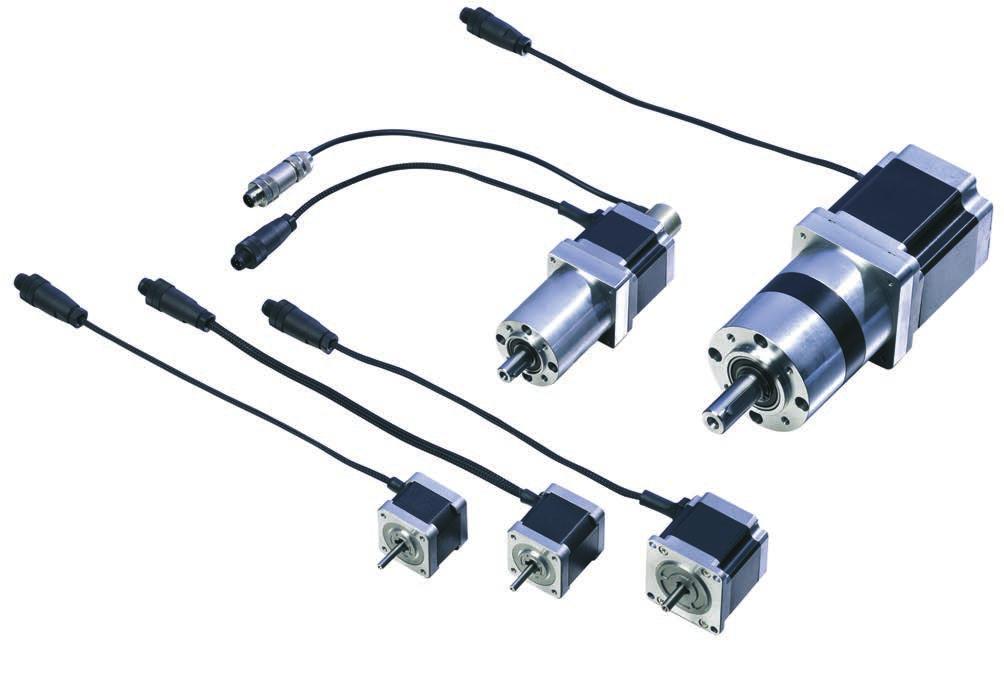
15 Product identification 6 Product identification 6.1 AS1000 supply schedule Please check that the delivery includes the following items: AM1000 series motor Connecting cable with 4-pin M12 connector (underside firmly connected) Online documentation at Scope of supply The M12 mating connectors are not included! Note The following accessories are available on request: Second shaft end for AS1020, AS1050 and AS1060 Encoder with connection cable and 5-pin, screened M12 socket Preassembled motor and feedback cable Planetary gear, AG1000 series 6.2 AS1000 name plate Version:

16 Product identification 6.3 AS1000 type key 16 Version: 3.6

17 Technical description 7 Technical description 7.1 Design of the motors Beckhoff stepper motors of the AS1000 series are synchronous motors with a large number of poles. They are classified as direct drives. The stepper motors of the AS1000 series are characterized by a high holding torque and very good positioning capability. Thanks to sophisticated control of the stator windings in full-step or micro-step mode, individual steps or partial steps can be executed directly without a feedback system. This feature distinguishes stepper motors from servomotors, thus representing a cost-effective alternative approach. Excessive acceleration and fast load cycles can result in the stepper motor being unable to follow the rotating field and therefore "losing steps". The encoder option can improve matters in this situation. The stepper motor has its highest torque in the lower speed range. At standstill, the stepper motor is characterized by a very high holding torque. In many applications, this eliminates the need for a holding brake. In the Beckhoff stepper motor terminals a suitable current curve can be stored for any speed or load profile. This serves to optimally adapt the thermal load of the motor. Beckhoff stepper motors are used as actuators or auxiliary axes in machine construction and automation applications. In conjunction with the stepper motor output stages and the Beckhoff TwinCAT automation system, this facilitates integration of cost-effective axes into the overall application. In order to simplify the electrical connection, the stepper motors are equipped with pre-assembled plug connectors. Planetary gear units, incremental encoders and pre-assembled connection cables are available as accessories. Version:
 -10 C to +50 C Permissible ambient temperature (transport/ storage) Permissible air humidity Permissible level of contamination Corrosion")
18 Technical description 7.2 General technical data Insulation class Temperature change at rated current Insulation resistance Class B (130 C) according to IEC60085 Max. 80 K 100 MΩ Permissible ambient temperature (operation) -10 C to +50 C Permissible ambient temperature (transport/ storage) Permissible air humidity Permissible level of contamination Corrosion protection Permissible operating altitude Maximum cable length between motor and terminal Special operating conditions Correct installation position Ventilation Protection class (doesn t apply to the shaft bushing) -25 to % to 90%, non-condensing Contamination level 2 according to EN60204/ EN50178 Under extreme operating conditions, special measures must be agreed with the manufacturer, and implemented by the user. Up to 1000 m above sea level 10 m The applicability of the Beckhoff AS1000 stepper motor is to be determined for each individual case. Application in harsh operating or environmental conditions requires coordination between manufacturer and user. Horizontal or vertical Ensure adequate ventilation of the motors. AS1010 AS1050: IP43 AS1060: IP Standard features Style The design of the AS1010 and AS1020 stepper motors is intended for flange mounting based on installation types IM B14, IM V18 and IM V19. The design of the AS1030/AS1050 and AS1060 stepper motors is intended for flange mounting based on installation types IM B5, IM V1 and IM V3. The permitted mounting positions are specified in the technical data. Attention Destruction of the motors Installation positions IM V1 and IM V3 may result in liquid entering the motor and associated damage. 18 Version: 3.6
19 Technical description Shaft end, A-side The force transfer is friction-locked (backlash-free), via a clutch, via the cylindrical shaft end A, or optionally as a form-locking connection via a feather key groove according to DIN6885. Radial force If the motors drive via pinions or toothed belts, then high radial forces will occur. Axial force Axial forces occur when assembling pinions or pulleys on the shaft. Coupling Double-coned collets, possibly in association with metal bellows couplings, have proven themselves as excellent, zero backlash coupling elements Flange Flange dimensions according to IEC standard, fit j6, accuracy according to DIN Tolerance class: N Connection technology The motors are equipped with connecting cables (300 mm) and M12 connectors for the power supply and the feedback signals (encoders only). The mating connectors are not included in the scope of supply. Ready-made extension cables in different lengths are available as accessories Feedback system Feedback system Resolution Comment Incremental encoders 200 increments Only for AS1020/AS1050/ AS1060 Incremental encoders 1024 increments Only for AS1020/AS1050/ AS Options Feather key Only the AS1060 is optionally available with groove and feather key. 7.5 Transport, assembly and disassembly CAUTION Personal injuries! Protective clothing, protective gloves and safety boots must be worn at all times during transport, assembly and disassembly. Do not step under suspended motors. The motors of the AS1000 series can be moved without auxiliary equipment. Version:
20 Mechanical installation 8 Mechanical installation 8.1 Important notes Destruction of the motors Attention Protect the motors from unacceptable stresses. Take care, especially during transport and handling, that components are not bent and that insulation clearances are not altered. The site must be free of conductive and aggressive material. For V1/V3-mounting (shaft end upwards), make sure that no liquids can enter the bearings. If an encapsulated assembly is required, please consult our applications department beforehand. Ensure unhindered ventilation of the motors and observe the permissible ambient and flange temperatures. For ambient temperatures above 50 C please consult our applications department beforehand. Stepper motors are precision devices. The flange and shaft are especially vulnerable during storage and assembly. It is important to use the locking thread which is provided to tighten up couplings, gear wheels or pulleys and warm up the drive components, where possible. Blows or the use of force will lead to damage to the ball bearings, the shaft, the holding brake and the feedback system. Wherever possible, use only backlash-free, frictionally-locking collets or couplings. Ensure correct alignment of the couplings. A displacement will cause unacceptable vibration and the destruction of the ball bearings and the coupling. For toothed belts, it is vital to observe the permissible radial forces. An excessive radial load on the shaft will significantly shorten the service life of the motor. Avoid axial loads on the motor shaft, as far as possible. Axial loading significantly shortens the service life of the motor and can result in malfunction of the brake. In any case, avoid creating a mechanically constrained motor shaft mounting by using a rigid coupling with additional external bearings (e.g. in a gearbox). Check compliance with the permitted radial and axial loads FR and FA. When using a toothed belt drive, the minimum permitted diameter of the pinion follows from the equation: 20 Version: 3.6

21 Mechanical installation 8.2 Installing the stepper motor When assembling, make sure that the fastening of the stepper motor is not mechanically overdetermined. Avoid warping, particularly when assembling the shaft. 8.3 Installing the incremental encoder (type 2420) If the stepper motor is ordered with the incremental encoder, the motor and the encoder are fitted in the factory. Retrospective installation of the encoder is only possible, if the stepper motor was ordered with a second shaft end and a hole for the locating pin. The locating pin provides torque support and must be secured with industrial adhesive (e.g. Loctite). Install the encoder with clutch on the shaft Carefully tighten the clamping hub Technical data of the encoder Stepper motors are designed for positioning tasks. Beckhoff stepper motors have a step angle of 1.8 (which is 200 steps/rotation). Stepper motor terminals enable each individual step to be approached. This enables positioning without feedback / encoder. The micro-stepping mode of the stepper motor terminal can be used to improve the physical resolution further. This causes the physical resolution to be multiplied by the microstep factor. The stepping pattern can be adjusted from full steps, through half steps down to 64 micro-steps. It is possible that, when overloaded, a stepper motor cannot keep up with the desired number of steps. This is referred to as the stepper motor "losing steps". It is therefore possible, optionally, to add an incremental encoder. This requires a second shaft end at the stepper motor. For stepper motors with incremental encoder, the stepper motor output stage KL2541 / EL7041 / EL7037 or EP must be used. Mechanical properties for 200 and 1024 steps per revolution Speed Max. 6,000 rpm Moment of inertia of the rotor Approx. 0.1 x 10⁻⁶ kgm 2 Starting torque Weight Protection class according to EN < 0.01 Nm Approx kg IP 64 (for housing) Working temperature range -20 C +75 C Operating temperature range -20 C +80 C Shaft Shock resistance Vibration resistance Shaft: Brass Housing: Aluminium In accordance with DIN-IEC : 1000 m/s², (6 ms) In accordance with DIN-IEC 06/02/1968: 100 m/s², (10 to 2000 Hz) Version:
22 Mechanical installation Electrical properties for 200 and 1024 steps per revolution Output circuit Supply voltage Current consumption (no load) Permitted load/channel Pulse frequency Signal level high Signal level low push-pull V DC Standard: 45 ma Maximum 150 ma ± 30 ma Max. 200 khz Min. UB-3 V Max. 2,5 V Rise time tr Max. 1 µs Fall time tf Max. 1 µs Short-circuit protected outputs CE conform Yes according to EN , EN , EN and EN Installing the planetary gear If the stepper motor is ordered together with the planetary gear, the motor and the gear unit are fitted in the factory. For retrospective installation please note the following: The planetary gear of the AG1000-xxxx series are supplied with a separate adapter shaft and integrated sun wheel. Slide the adapter shaft onto the stepper motor shaft up to the end stop and secure it with a heat resistant, industrial adhesive (e.g. Loctite). Before applying the adhesive to the adapter shaft, clean the motor shaft with a suitable solvent. A cotter pin (not included) can be inserted through the mounting hole. Slide the gear unit onto the adapter shaft. Screw the gear flange to the motor flange. Ensure the screws are tightened evenly to avoid tensions in the component Technical data of the planetary gear units Beckhoff offers planetary gears for stepper motors in order to increase the torque or to improve the mass inertia ratio. Stepper motors whose flanges have dimensions of 56 mm or above can be fitted with low-play planetary gears. AG1000-+PM052.00x Rated torque 4 Nm 20 Nm Acceleration torque 6 Nm 30 Nm Gear play 0,7 0,5 Max. radial power 200 N 400 N Max. axial power 60 N 80 N Stepper motors AS1030 and AS1050 AS1060 Fastening screws 4 x M4 4 x M6 Tightening torque 2.8 Nm 9 Nm AG1000-+PM081.00x x = ratio 4 (3.7 exactly or 63/17 as a fraction), ratio 7 (6.75 exactly or 27/4 as a fraction) Gear rim and planet wheels in steel design, straight-toothed. Lubricant Klübersynth GE Version: 3.6
23 Electrical installation 9 Electrical installation 9.1 Important notes DANGER Attention Serious risk of injury through electric shock! Only staff qualified and trained in electrical engineering are allowed to wire up the motor. Check the assignment of the stepper motor output stage and the motor. Compare the rated voltage and the rated current of the devices. Always make sure that the motors are de-energized during assembly and wiring, i.e. no voltage may be switched on for any piece of equipment which is to be connected. Ensure that the control cabinet remains turned off (barrier, warning signs etc.). The individual voltages will only be turned on again during commissioning. Control and power leads may be live, even if the motor is not running. Smooth operation Ensure that the motor is grounded properly. See below for further information regarding EMC shielding and earthing. Earth the mounting plate and motor housing. Further details of connection types can be found in Section 8.2 Use only cables approved by Beckhoff for use with the AS1000 stepper motors. Wiring: ð Connecting the feedback cable (optional) ð Connect the motor cables ð Shielding at both ends (shield terminal or EMC plug) Attention HF interference The ground symbol, which you will find in the wiring diagrams, indicates that you must provide an electrical connection, with as large a surface area as possible, between the unit indicated and the mounting plate in the control cabinet. This connection is to suppress HF interference and must not be confused with the PE (protective earth) symbol (protective measure according to EN 60204). Follow the instructions in the circuit diagrams in Sections 8.3 to 8.6 Version:
24 Electrical installation 9.2 Connection of motors with preassembled cables Beckhoff offers preassembled motor and feedback cables for safe, faster and flawless installation of the motors. Beckhoff cables have been tested with regard to the materials, shielding and connectors used. They ensure proper functioning and compliance with statutory regulations such as EMC, UL etc. The use of other cables may lead to unexpected interference and invalidate the warranty. Carry out the wiring in accordance with the valid standards and regulations. Only use our preassembled shielded cables for the power and feedback connections. The shielding should match the specifications in sections 8.4 to Incorrectly installed shielding inevitably leads to EMC interference. The motor connector and the mating connector of the Beckhoff motor cable is a special version with 5 A current-carrying capacity. The use of other M12 connector can lead to overload. 24 Version: 3.6

 1 Red Phase 1 2 Yellow Phase 2 3")
25 Electrical installation 9.3 Electrical components Motor connector Motor winding Motor connector View X The stepper motors are equipped with a 300 mm long connection cable and a preassembled M12 connector plug. Contact Color of conductor Signal Round connector 4- pin (view x ) 1 Red Phase 1 2 Yellow Phase 2 3 Orange Phase 3 4 Blue Phase Encoder connector The optional encoder is equipped with a 300 mm long, screened connection cable and a screened, preassembled M12 connector plug. Pin Color of conductor Signal Round connector 5- pin (view X ) 1 White 0 V 2 Brown +Ub 3 Green Track A 4 Yellow Track B 5 Grey Track 0 Version:
26 Electrical installation 9.4 Connection diagram KL Version: 3.6
27 Electrical installation 9.5 Connection diagram KL2541 Version:
28 Electrical installation 9.6 Connection diagram EL Version: 3.6
29 Electrical installation 9.7 Connection diagram EL7041 Version:
30 Electrical installation 9.8 Connection diagram EL Version: 3.6

31 Electrical installation 9.9 Connection diagram EL7047 Version:

32 Electrical installation 9.10 Connection diagram EP Version: 3.6

33 Commissioning 10 Commissioning 10.1 Important notes DANGER Attention Serious risk of injury! Only specialist personnel with extensive knowledge in the areas of electrical engineering / drive technology are allowed to install and commission the equipment. The surface temperature of the motor can exceed 100 C in operation. Check (measure) the temperature of the motor. Wait until the motor has cooled down below 40 C before touching it. Make sure that, even if the drive starts to move unintentionally, no danger can result for personnel or machinery. Overloading of the gear! With motor / gear combinations can in case of failure (mechanical blockage of the power train) due to high ratio, the gear will be overloaded. To prevent this, make sure that the motor rated torque and the motor peak torque is limited in the servo drive. Example: Motor rated torque / motor peak torque: 1 Nm / 5 Nm Gear rated torque / gear peak torque: 15 Nm / 24 Nm Gear ratio: i = 10 The motor rated torque is not limited. The motor peak torque is limited to 2,4 Nm Guide for commissioning The procedure for commissioning is described as an example. A different method may be appropriate or necessary, depending on the application of the equipment. Check the assembly and orientation of the motor. Check the drive components (coupling, gear unit, pulley) for the correct seating and setting (observe the permissible radial and axial forces). Check the wiring and connections to the motor and the servo drive. Check that the earthing is correct. Check whether the rotor of the motor revolves freely (release the brake, if necessary). Listen out for grinding noises. Check that all the required measures against accidental contact with live and moving parts have been carried out. Carry out any further tests which are specifically required for your system. Now commission the motor according to the commissioning instructions. Version:
34 Commissioning 10.3 Troubleshooting The following table is to be seen as a First Aid box. There can be a large number of different reasons for a fault, depending on the particular conditions in your system. The fault causes described below are mostly those which directly influence the motor. Our applications department can give you further help with your problems. Error Possible cause Measures to remove the cause of the fault Motor doesn t rotate Break in setpoint lead Motor phases in wrong sequence Drive is mechanically blocked Check setpoint lead Correct the phase sequence Check mechanism Motor runs away Motor phases in wrong sequence Correct the phase sequence Motor oscillates Error message: output stage fault Error message: feedback Break in the shielding of the feedback cable Amplification to high Motor cable has short circuit or earth leakage Motor has short circuit or earth leakage Connector is not properly plugged in Break in cable, cable crushed or similar Replace the feedback cable Use motor default values Replace motor cable Replace motor Check the plug connector Check cables 34 Version: 3.6
35 Technical data 11 Technical data All data valid for 40 C ambient temperature and 100 K overtemperature of the winding. The data can have a tolerance of +/- 10%. If a gear unit is attached the power may be reduced by up to 20 %. This loss in performance has thermal reasons, since a gear unit that is subject to warming is installed at the motor flange intended for heat dissipation. Term definitions Standstill torque M0 [Nm] The standstill torque can be maintained indefinitely at a speed n<100 rpm and rated ambient conditions. Rotor moment of inertia J [kgcm²] The constant J is a measure of the acceleration capability of the motor. For instance, at I0 the acceleration time tb from 0 to 3000 rpm is given as: with M0 in Nm and J in kgcm2 Winding inductance L [mh] The winding inductance indicates the motor inductance. It is the average value for one motor revolution, with two energized phases, at 1 khz. Saturation of the motor must be taken into account Step mode and limit speeds The Beckhoff stepper motor terminals are capable of approx. 125,000 steps per second. Beckhoff stepper motors have a step angle of 1.8 or 200 steps per revolution. Step mode Full step 1/2 1/4 1/8 1/16 1/32 1/64 Limit speed [rpm] (theoretical) (theoretical) (theoretical) 4,688 (theoretical) , In practice, the design and construction of the stepper motor limit the maximum speed of rotation. Normally, stepper motors are in fact only used for applications with rated rotation speeds well below 1000 per minute. Version:
36 Technical data 11.2 AS Technical data Symbol [Unit] AS1010 Rated supply voltage V DC Rated current A 1,0 Rated power W 8,4 Standstill torque M o [Nm] 0,38 Winding resistance Ph-Ph R 20 [Ω] 4,10 Winding inductance Ph-Ph L [mh] 9,50 Rotor moment of inertia J [kg cm²] 0,056 Resolution [steps] 1.8 / 200 full steps Weight [kg] 0.31 Cogging torque M r [Nm] ~ Mechanical data Symbol [Unit] AS1010 Axial load [N] 10 Radial load 0 mm from the shaft end [N] 22 Radial load 5 mm from the shaft end [N] 26 Radial load 10 mm from the shaft end [N] 33 Radial load 15 mm from the shaft end [N] 46 Backlash at standstill [ ] ± 0,09 Axial backlash max. 1) [mm] 0,075 Radial backlash max. 2) [mm] 0,025 Bearing life [h] ) measured at a load of 4.4 N (AS1010 / AS1020) 2) measured at a load of 4.4 N 36 Version: 3.6
37 Technical data Characteristic curve diagram for AS Version:

38 Technical data Dimensional drawing AS Version: 3.6
39 Technical data 11.3 AS1020-0xxx Technical data Symbol [Unit] AS1020 Rated supply voltage V DC Rated current A 1,0 Rated power W 10,0 Standstill torque M o [Nm] 0,5 Winding resistance Ph-Ph R 20 [Ω] 4,80 Winding inductance Ph-Ph L [mh] 9,50 Rotor moment of inertia J [kg cm²] 0,074 Resolution [steps] 1.8 / 200 full steps Weight [kg] 0,39 Cogging torque M r [Nm] ~ Mechanical data Symbol [Unit] AS1020 Axial load [N] 10 Radial load 0 mm from the shaft end [N] 22 Radial load 5 mm from the shaft end [N] 26 Radial load 10 mm from the shaft end [N] 33 Radial load 15 mm from the shaft end [N] 46 Backlash at standstill [ ] ± 0,09 Axial backlash max. 1) [mm] 0,075 Radial backlash max. 2) [mm] 0,025 Bearing life [h] ) measured at a load of 9 N 2) measured at a load of 4.4 N Version:
40 Technical data Characteristic curve diagram for AS1020-0xxx 40 Version: 3.6

41 Technical data Dimensional drawing AS1020-0xxx Version:
42 Technical data 11.4 AS Technical data Symbol [Unit] AS1030 Rated supply voltage V DC Rated current A 1,5 Rated power W 19,5 Standstill torque M o [Nm] 0,6 Winding resistance Ph-Ph R 20 [Ω] 0,80 Winding inductance Ph-Ph L [mh] 3,80 Rotor moment of inertia J [kg cm²] 0,21 Resolution [steps] 1.8 / 200 full steps Weight [kg] 0,68 Cogging torque M r [Nm] ~ Mechanical data Symbol [Unit] AS1030 Axial load [N] 15 Radial load 0 mm from the shaft end [N] 52 Radial load 5 mm from the shaft end [N] 65 Radial load 10 mm from the shaft end [N] 85 Radial load 15 mm from the shaft end [N] 123 Backlash at standstill [ ] ± 0,054 Axial backlash max. 1) [mm] 0,075 Radial backlash max. 2) [mm] 0,025 Bearing life [h] ) measured at a load of 9 N 2) measured at a load of 4.4 N 42 Version: 3.6
43 Technical data Characteristic curve diagram for AS Version:

44 Technical data Dimensional drawing AS Version: 3.6
45 Technical data 11.5 AS1050-0xxx Technical data Symbol [Unit] AS1050 Rated supply voltage V DC Rated current A 5,0 Rated power W 27,5 Standstill torque M o [Nm] 1,2 Winding resistance Ph-Ph R 20 [Ω] 0,28 Winding inductance Ph-Ph L [mh] 0,86 Rotor moment of inertia J [kg cm²] 0,36 Resolution [steps] 1.8 / 200 full steps Weight [kg] 1,00 Cogging torque M r [Nm] ~ Mechanical data Symbol [Unit] AS1050 Axial load [N] 15 Radial load 0 mm from the shaft end [N] 52 Radial load 5 mm from the shaft end [N] 65 Radial load 10 mm from the shaft end [N] 85 Radial load 15 mm from the shaft end [N] 123 Backlash at standstill [ ] ± 0,054 Axial backlash max. 1) [mm] 0,075 Radial backlash max. 2) [mm] 0,025 Bearing life [h] ) measured at a load of 9 N 2) measured at a load of 4.4 N Version:
46 Technical data Characteristic curve diagram for AS1050-0xxx 46 Version: 3.6

47 Technical data Dimensional drawing AS1050-0xxx Version:
48 Technical data 11.6 AS1060-xxxx Technical data Symbol [Unit] AS1060 Rated supply voltage V DC Rated current A 5,0 Rated power W 68,8 Standstill torque M o [Nm] 5,0 Winding resistance Ph-Ph R 20 [Ω] 0,36 Winding inductance Ph-Ph L [mh] 2,80 Rotor moment of inertia J [kg cm²] 3,0 Resolution [steps] 1.8 / 200 full steps Weight [kg] 2,85 Cogging torque M r [Nm] ~ Mechanical data Symbol [Unit] AS1060 Axial load [N] 60 Radial load 0 mm from the shaft end [N] 191 Radial load 5 mm from the shaft end [N] 234 Radial load 10 mm from the shaft end [N] 301 Radial load 15 mm from the shaft end [N] 421 Backlash at standstill [ ] ± 0,09 Axial backlash max. 1) [mm] 0,075 Radial backlash max. 2) [mm] 0,025 Bearing life [h] ) measured at a load of 9 N 2) measured at a load of 4.4 N 48 Version: 3.6
49 Technical data Characteristic curve diagram for AS1060-xxxx Version:

50 Technical data Dimensional drawing AS1060-0xxx 50 Version: 3.6

51 Technical data Dimensional drawing AS1060-1xxx Version:
52 Appendix 12 Appendix 12.1 Support and Service Beckhoff and their partners around the world offer comprehensive support and service, making available fast and competent assistance with all questions related to Beckhoff products and system solutions. Beckhoff's branch offices and representatives Please contact your Beckhoff branch office or representative for local support and service on Beckhoff products! The addresses of Beckhoff's branch offices and representatives round the world can be found on her internet pages: You will also find further documentation for Beckhoff components there. Beckhoff Headquarters Beckhoff Automation GmbH & Co. KG Huelshorstweg Verl Germany Phone: +49(0)5246/963-0 Fax: +49(0)5246/ Beckhoff Support Support offers you comprehensive technical assistance, helping you not only with the application of individual Beckhoff products, but also with other, wide-ranging services: support design, programming and commissioning of complex automation systems and extensive training program for Beckhoff system components Hotline: +49(0)5246/ Fax: +49(0)5246/ Beckhoff Service The Beckhoff Service Center supports you in all matters of after-sales service: on-site service repair service spare parts service hotline service Hotline: +49(0)5246/ Fax: +49(0)5246/ Version: 3.6
Operation Manual. Stepper motor AS2000. Version: Date:
 Operation Manual Version: Date: 1.1 2019-01-25 Table of content Table of content 1 Foreword... 5 1.1 Notes on the documentation... 5 1.2 Documentation Issue Status... 6 1.3 Appropriate use... 6 2 Guidelines
Exchange of rollers from the XTS-Mover
 Service documentation for AT901-0050-0550 and AT9011-00x0-0550 Version: Date: 1.0 0.10.017 Table of contents Table of contents 1 Foreword... 5 1.1 Notes on the documentation... 5 1. Documentation issue
Description AX5806. List of permissible motors. Version: Date:
 Description AX5806 List of permissible motors Version: 1.3.0 Date: 2017-11-15 Table of contents Table of contents 1 Foreword 3 1.1 Notes on the manual 3 1.1.1 Intendent audience 3 1.1.2 Origin of the
Planetary gear unit AG1000-+PMxx
 Operating manual for stepper motors AS1000 Version: Date: 1.4 2018-03-15 Table of content Table of content 1 Foreword... 5 1.1 Notes on the documentation... 5 1.2 Documentation issue status... 6 1.3 Intended
Highend planetary gear unit AG2300+SPxxx
 Operation Manual Highend planetary gear unit AG2300 Version: Date: 1.2 2017-07-26 Table of content Table of content 1 Foreword... 5 1.1 Notes on the documentation... 5 1.2 Documentation issue status...
Synchronous servomotor AM8100
 Documentation for compact drive technology Version: Date: 2.0 2018-03-06 Documented motors AM8100 AM8tuv-wxyz Documented motors AM8100 Standstill torque Standstill current Rated speed at rated supply
TGN, TGH AND TGT SERVOMOTORS
 TGN, TGH AND TGT SERVOMOTORS Instruction manual. Information furnished by is believed to be accurate and reliable. However, no responsibility is assumed by TG Drives for its use. TG Drives reserves the
Documentation. Synchronous Servomotor AM3100. Version: 1.4 Date:
 Documentation Synchronous Servomotor AM3100 Version: 1.4 Date: 2012-04-20 Documented motors Drive Technology Documented motors AM3100 Standstill torque Standstill current Rated speed Rated supply voltage
Synchronous Servomotors AM8000 & AM8500
 Documentation Version: Date: 3.4 2017-11-27 Table of contents Table of contents 1 Foreword... 7 1.1 Notes on the documentation... 7 1.2 Documentation Issue Status... 8 1.3 Appropriate use... 9 2 Guidelines
Servo motors AM8000 and AM8500
 Documentation Fan cooled Version: Date: 1.9 2017-09-18 Table of contents Table of contents 1 Foreword... 5 1.1 Notes on the documentation... 5 1.2 Documentation Issue Status... 6 1.3 Appropriate use...
Technical Documentation
 Technical Documentation Product manual Holding brake controller Document: 0198441113316 Edition: V1.00, 03.2006 Important information The drive systems described here are products for general use that
Toothed belt axis ELGC-TB-KF. Operating instruction [ ]
![Toothed belt axis ELGC-TB-KF. Operating instruction [ ]](/thumbs/83/87984161.jpg "Toothed belt axis ELGC-TB-KF. Operating instruction [ ]") Toothed belt axis ELGC-TB-KF en Operating instruction 8068220 2017-02 [8068222] Original instructions Identification of hazards and instructions on how to prevent them: Danger Immediate dangers which can
Toothed belt axis ELGC-TB-KF en Operating instruction 8068220 2017-02 [8068222] Original instructions Identification of hazards and instructions on how to prevent them: Danger Immediate dangers which can
SMH High Torque Density
 SMH High Torque Density AC Synchronous Servo Motor Catalogue Version:C Date: January, 207 Kinavo Servo Motor(Changzhou)Ltd. Tel.: +8-0-88037 Fax: +8-0-88072 Website: http://www.kinavo.com Add.: Building
Synchronous Servomotors Series 6SM Technical description, Installation, Commissioning Edition 10/05
 www.danahermotion.com Synchronous Servomotors Series 6SM27..107 Technical description, Installation, Commissioning Edition 10/05 Already published editions Edition Comments 03 / 98 First edition 09 / 98
ILA2D572TC1F0 integrated drive ILA with servo motor V - DeviceNet - indus connector
 Characteristics integrated drive ILA with servo motor - 24..48 V - DeviceNet - indus connector Main Range of product Product or component type Device short name Motor type Number of motor poles 6 Phase
Documentation AG2800. Version: Date:
 Documentation Version: Date: 1.3 2017-07-26 Table of content Table of content 1 Foreword... 5 1.1 Notes on the documentation... 5 1.2 Documentation issue status... 6 1.3 Intended use... 6 2 Safety...
ILE2K661PC1A1 brushless dc motor V- EtherNet/IP interface - L = 174 mm- 18:1
 Characteristics brushless dc motor 24..48V- EtherNet/IP interface - L = 174 mm- 18:1 Main Range of product Product or component type Device short name Motor type Number of motor poles 6 Network number
BoWex FLE-PA. BoWex FLE-PAC. KTR-N Sheet: Edition: EN 1 of BoWex FLE-PA / FLE-PAC Operating/Assembly instructions
 1 of 17 is a torsionally rigid flange coupling. It is able to compensate for shaft misalignment, for example caused by manufacturing inaccuracies, thermal expansion, etc. BoWex FLE-PA BoWex FLE-PAC Drawn:
standards based cylinder DNCI Operating instructions e [ ]
![standards based cylinder DNCI Operating instructions e [ ]](/thumbs/86/93364847.jpg "standards based cylinder DNCI Operating instructions e [ ]") standards based cylinder DNCI en Operating instructions 8072823 2017-05e [8072825] Original instructions Identification of hazards and instructions on how to prevent them: Danger Immediate dangers which
standards based cylinder DNCI en Operating instructions 8072823 2017-05e [8072825] Original instructions Identification of hazards and instructions on how to prevent them: Danger Immediate dangers which
Spindle axis ELGC-BS-KF. Operating instructions [ ]
![Spindle axis ELGC-BS-KF. Operating instructions [ ]](/thumbs/87/97202885.jpg "Spindle axis ELGC-BS-KF. Operating instructions [ ]") Spindle axis ELGC-BS-KF en Operating instructions 8067243 2017-01 [8067245] Original instructions Identification of hazards and instructions on how to prevent them: Danger Immediate dangers which can lead
Spindle axis ELGC-BS-KF en Operating instructions 8067243 2017-01 [8067245] Original instructions Identification of hazards and instructions on how to prevent them: Danger Immediate dangers which can lead
Planar surface gantry EXCM-30. Instructions. Mechanical installation b [ ]
![Planar surface gantry EXCM-30. Instructions. Mechanical installation b [ ]](/thumbs/91/106333591.jpg "Planar surface gantry EXCM-30. Instructions. Mechanical installation b [ ]") Planar surface gantry EXCM-30 Instructions Mechanical installation 804447 605b [8044434] EXCM-30 Translation of the original instructions LOCTITE is a registered trademark of its respective trademark holder
Planar surface gantry EXCM-30 Instructions Mechanical installation 804447 605b [8044434] EXCM-30 Translation of the original instructions LOCTITE is a registered trademark of its respective trademark holder
SERVO MOTORS BRUSHLESS SERVO MOTORS OPERATING INSTRUCTIONS 2016
 SERVO MOTORS BRUSHLESS SERVO MOTORS OPERATING INSTRUCTIONS 2016 3009/16 en Ed.02.2016 Read these Operating Instructions before performing any transportation, installation, commissioning, maintenance or
ELGC-BS-KF. Spindle axis. Instructions Operating c [ ]
![ELGC-BS-KF. Spindle axis. Instructions Operating c [ ]](/thumbs/88/115778972.jpg "ELGC-BS-KF. Spindle axis. Instructions Operating c [ ]") ELGC-BS-KF Spindle axis Instructions Operating 8095590 8095590 2018-08c [8095592] Translation of the original instructions 2 Festo ELGC-BS-KF 2018-08c Table of contents 1 Further applicable documents...
ELGC-BS-KF Spindle axis Instructions Operating 8095590 8095590 2018-08c [8095592] Translation of the original instructions 2 Festo ELGC-BS-KF 2018-08c Table of contents 1 Further applicable documents...
Installation and Operational Instructions for ROBATIC -clutch Types _.0 and _.0 Sizes 3 7
 Please read these Installation and Operational Instructions carefully and follow them accordingly! Ignoring these Instructions may lead to malfunction or to clutch failure, resulting in damage to other
Assembly and Maintenance Manual Type ASNU
 Assembly and Maintenance Manual Type ASNU Hatschekstr.36 69126 Heidelberg Germany Tel +49(0)6221 30470 Fax +49(0)6221 304731 info@stieber.de www.stieber.de Date of issue: 30.05.2018 GB Revision: 0 U:\EngUsers\!ProduktDoku\1AAA_Einbauerklaerung_Wartungsanleitung_Konformitaetserklaerung\1AAA_Wartungsanleitungen\Orginal_Worddatei\_ASNU.docx
Mini slide EGSC-BS-KF. Operating instructions b [ ]
![Mini slide EGSC-BS-KF. Operating instructions b [ ]](/thumbs/87/95253800.jpg "Mini slide EGSC-BS-KF. Operating instructions b [ ]") Mini slide EGSC-BS-KF en Operating instructions 8081968 2017-11b [8081970] Translation of the original instructions EGSC-BS-KF-EN Identification of hazards and instructions on how to prevent them: Danger
Mini slide EGSC-BS-KF en Operating instructions 8081968 2017-11b [8081970] Translation of the original instructions EGSC-BS-KF-EN Identification of hazards and instructions on how to prevent them: Danger
ILA1F572PB1F0 integrated drive ILA with servo motor V - CANopen - PCB connector
 Characteristics integrated drive ILA with servo motor - 24..36 V - CANopen - PCB connector Product availability : Non-Stock - Not normally stocked in distribution facility Price* : 1860.00 USD Main Range
Operating Manual (Edition 04/2004) sinamics. Braking Module / Braking Resistor SINAMICS G130
 sinamics. Braking Module / Braking Resistor SINAMICS G130") Operating Manual (Edition 04/2004) sinamics Braking Module / Braking Resistor SINAMICS G130 04/04 Contents Contents 1 Safety Information 1-1 2 General 2-1 3 Mechanical Installation 3-1 4 Connection 4-1
Operating Manual (Edition 04/2004) sinamics Braking Module / Braking Resistor SINAMICS G130 04/04 Contents Contents 1 Safety Information 1-1 2 General 2-1 3 Mechanical Installation 3-1 4 Connection 4-1
Commissioning Manual AC Servo Actuator LynxDrive SIEMENS SIMODRIVE
 Commissioning Manual AC Servo Actuator LynxDrive SIEMENS SIMODRIVE 06/2017 1017913 Content 1. General... 3 1.1 Description of Safety Alert s... 4 1.2 Disclaimer and Copyright... 4 2. Safety and Installation
Assembly and Maintenance Manual Type AS
 Assembly and Maintenance Manual Type AS Hatschekstr.36 69126 Heidelberg Germany Tel +49(0)6221 30470 Fax +49(0)6221 304731 info@stieber.de www.stieber.de Date of issue: 30.05.2018 GB Revision: 0 U:\EngUsers\!ProduktDoku\1AAA_Einbauerklaerung_Wartungsanleitung_Konformitaetserklaerung\1AAA_Wartungsanleitungen\Orginal_Worddatei\_AS.docx
ILE2T661PB1A3 brushless dc motor V - Modbus TCP interface - L = 174 mm - 54:1
 Characteristics brushless dc motor 24..48 V - Modbus TCP interface - L = 174 mm - 54:1 Product availability : Non-Stock - Not normally stocked in distribution facility Price* : 1540.00 USD Main Range of
Electromagnetic clutch-brake combinations INTORQ
 Electromagnetic clutch-brake combinations INTORQ 14.800 14.867 7.5 120 Nm setting the standard 2 CBC en 5/2005 Contents Clutch-brake combinations Product information 4 Type code 6 Design selection 8 Overview
ILE1B661PC1A1 brushless dc motor V - Profibus DP interface - L = 174 mm - 18:1
 Characteristics brushless dc motor 24..36 V - Profibus DP interface - L = 174 mm - 18:1 Product availability : Non-Stock - Not normally stocked in distribution facility Price* : 1640.00 USD Main Range
ILE1F661PC1A0 brushless dc motor V - CANopen DS301 interface - L = 122 mm - w/o gearbox
 Characteristics brushless dc motor 24..36 V - CANopen DS301 interface - L = 122 mm - w/o gearbox Main Range of product Product or component type Device short name Motor type Number of motor poles 6 Network
Overvoltage protection and voltage stabilization for Motion Control terminals
 Keywords Buffer capacitor Brake chopper Fieldbus Drive Stepper DC motor Output stage DC link Overload Recovery EtherCAT K-Bus Bus Terminal PLC Overvoltage protection and voltage stabilization for Control
ILE1F661PB1A0 brushless dc motor V - CANopen DS301 interface - L = 122 mm - w/o gearbox
 Characteristics brushless dc motor 24..36 V - CANopen DS301 interface - L = 122 mm - w/o gearbox Product availability : Stock - Normally stocked in distribution facility Price* : 840.00 USD Main Range
Appendix: Safety and application notes for... 15
 Contents Safety... 2 Warnings... 2 Symbols used in this manual... 2 Operator s safety... 2 Avoid filter module damage... 2 DC-link resonance... 2 Description... 3 Description... 3 Ordering numbers, 380-415
PrioVino Premier. Translation of Original Operating Instructions. Status: August First edition January 2018 / PrioVino GmbH
 PrioVino Premier Translation of Original Operating Instructions Status: August 2018 First edition January 2018 / PrioVino GmbH Reprint even in extracts only upon written permission by PrioVino GmbH (ISO
Installation, Operating & Maintenance Instructions. HV gate valve with pneumatic actuator. Series 110 DN mm (I. D.
 Installation, Operating & Maintenance Instructions HV gate valve with pneumatic actuator Series 110 DN 250 320 mm (I. D. 10" 12") This manual is valid for the following product ordering numbers: 11048-.
User Guide. Lubricus Lubrication System LUB-D1/LUB-D2/LUB-D3/LUB-D4 (24 VDC)
") User Guide Lubricus Lubrication System LUB-D1/LUB-D2/LUB-D3/LUB-D4 (24 VDC) version 04/2013 Content General Information 3 Warning 3 Scope of Supply 3 Overview 3 General safety details 4 Intended use 4
User Guide Lubricus Lubrication System LUB-D1/LUB-D2/LUB-D3/LUB-D4 (24 VDC) version 04/2013 Content General Information 3 Warning 3 Scope of Supply 3 Overview 3 General safety details 4 Intended use 4
3-phase stepping motors
 General Series of Features from Berger Lahr are: Powerful because the optimised internal geometry results in a high power intensity, meaning up to 50 % more torque than standard stepping motors of comparable
Assembly and Maintenance Manual Type RSBW
 Assembly and Maintenance Manual Type RSBW Hatschekstr. 36 69126 Heidelberg Germany Tel +49(0)6221 30470 Tel +49(0)6221 304731 info@stieber.de www.stieber.de Stieber Clutch Date of issue: 16/03/2017 GB
For air dampers and control valves of oil or gas burners
 7 813 Actuators For air dampers and control valves of oil or gas burners SQM33... Electromotoric actuators Torques: - SQM33.4 up to 1.2 Nm nominal output torque - SQM33.5 up to 3 Nm nominal output torque
PRO-TYP II. Single and 3-phase Test Adapter with Type 2 Plug for Testing Electric Charging Stations with PROFITEST MTECH+ and MXTRA
 PRO-TYP II Single and 3-phase Test Adapter with Type 2 Plug for Testing Electric Charging Stations with PROFITEST MTECH+ and MXTRA 3-349-884-03 1/10.15 Opening of Equipment / Repair The equipment may be
Table of contents. Three-phase asynchronous motors DA
 be in motion be in motion AC Asynchronous Motors DA 100-280 Table of contents 1. Three-phase asynchronous motor DA 100-280... 3 1.1. General technical data... 3 1.2. Ratings definition for ventilated
SERVO MOTORS BRUSHLESS SERVO MOTORS ATEX ZONE 2-22 OPERATING INSTRUCTIONS 2016
 SERVO MOTORS BRUSHLESS SERVO MOTORS ATEX ZONE 2-22 OPERATING INSTRUCTIONS 2016 3010/16 en Ed.10.2016 Read these Operating Instructions before performing any transportation, installation, commissioning,
AZ Series Motor OPERATING MANUAL. Introduction. Safety precautions. CE Marking
 HM-6244-3 OPERATING MANUAL Closed Loop Stepping and Driver Package AZ Series Introduction Before use Only qualified personnel should work with the product. Use the product correctly after thoroughly reading
DRIVESPIN ROTARY ACTUATORS
 DRIVESPIN ROTARY ACTUATORS Installation and service manual. 2/2017 Information furnished by TG Drives is believed to be accurate and reliable. However, no responsibility is assumed by TG Drives for its
Instruction Manual. Harmonic Filter AHF 005/010. Drives Solutions
 Harmonic Filter AHF 005/010 Instruction Manual Drives Solutions Contents Safety... 2 Warnings... 2 Symbols used in this manual... 2 Operator s safety... 2 Avoid filter module damage... 2 DC-link resonance...
Electric cylinder ESBF-BS/-LS Operating instructions b [ ]
![Electric cylinder ESBF-BS/-LS Operating instructions b [ ]](/thumbs/81/84386573.jpg "Electric cylinder ESBF-BS/-LS Operating instructions b [ ]") Electric cylinder ESBF-BS/-LS-32... 100 en Operating instructions 8076295 2017-11b [8079297] Translation of the original instructions Symbols: Warning Installation and commissioning may only be performed
Electric cylinder ESBF-BS/-LS-32... 100 en Operating instructions 8076295 2017-11b [8079297] Translation of the original instructions Symbols: Warning Installation and commissioning may only be performed
Operating instructions Rotary actuators M135 M140 M150 M180. June 2012 / / EN
 Operating instructions Rotary actuators M135 M140 M150 M180 June 2012 / 118614 / EN General information General information Proof of amendment Copyright Subject to alterations Manufacturer Version Date
Operating / Assembly Instructions Type A and CS Coupling
 Page: 1 of 14 Subject Index 1. Technical Data 2. Hints 2.1. General Hints 2.2. Warning and Safety Hints. 2.3. General Hints to Danger. 2.4. Proper use. 3. Storage. 4. Assembly. 4.1. Coupling components.
AMxxxx Synchronous Servomotors
 AMxxxx Synchronous Servomotors One Cable Technology (OCT) for power and feedback with absolute encoder Backlash-free permanent magnet holding brake Rotatable speedtec plug Modular design Greatest possible
Stepper motors EMMS-ST
 q/w Worldwide: Superb: Easy: Festo core product range Covers 80% of your automation tasks Always in stock Festo quality at an attractive price Reduces procurement and storing complexity qready for dispatch
Rexroth IndraDyn E. Standard Motors MOT-FC for Frequency Converter Operation. Project planning manual R Edition 03
 Rexroth IndraDyn E Standard Motors MOT-FC for Frequency Converter Operation Project planning manual R911343624 Edition 03 Bosch Rexroth AG DOK-MOTOR*-MOT-FC*****-PR03-EN-P Title Type of Documentation Document
3242 G 024 BX4 CS/CC 24 3,6 18,2 77,3 1,6 / 12,4 9 / ball bearings, preloaded 0,015. stainless steel 370 electronically reversible
 Brushless DC-Servomotor with integrated Motion Controller and or CN interface 6 mnm For combination with Gearheads: 3/1, 32, 32/3, 32/3 S, 38/1, 38/1 S, 38/2, 38/2 S 3242... BX4 CS/CC 1 2 3 4 Nominal voltage
Economy planetary gear unit AG NPxxx
 Operation Manual compatible with planetary gear unit AG2210-+LPxxx Version: Date: 1.2 2018-03-28 Table of content Table of content 1 Foreword... 5 1.1 Notes on the documentation... 5 1.2 Documentation
SIMOTICS S-1FT7 Servomotors. The Compact Servomotors for High-Performance Motion Control Applications. Motors. Edition April 2017.
 Motors SIMOTICS S-1FT7 Servomotors The Compact Servomotors for High-Performance Motion Control Applications Brochure Edition April 2017 siemens.com/servomotors The Servomotors for High-Performance Applications
Operating Instructions for Roll-Up Door Operators / MDF
 Operating Instructions for Roll-Up Door Operators / MDF GB Roll-Up Door Operator / MDF / Rev. 0.0 1 1. Contents 3. General safety instructions 1. Contents 2 2. Key to symbols 2 3. General safety instructions
Appendix: Safety and application notes for 19
 Contents Safety 2 Warnings 2 Symbols used in this manual 2 Operator's safety 2 Avoid filter module damage 2 DC-link resonance 2 Description 3 Description 3 Ordering numbers, 380-415 V, 50 Hz 4 Ordering
BMH. Servo motor Motor manual V2.1, , V2.1,
 BMH Servo motor Motor manual V2.1, 03.2016 www.schneider-electric.com The information provided in this documentation contains general descriptions and/or technical characteristics of the performance of
2232 S 024 BX4 CSD/CCD 24 12,4 6,4 67,7 2 / 17 4,1 / ball bearings, preloaded 0,015. stainless steel 77 electronically reversible
 NEW Brushless DC-Servomotor with integrated Motion Controller and or CN interface 18 mnm For combination with Gearheads: 22F, 22/7, 26 2232... BX4 CSD/CCD 1 2 3 4 Nominal voltage Terminal resistance, phase-phase
Technical Manual Electrical Power Supply System T4002
 Technical Manual Electrical Power Supply System T400 MOZELT GmbH & Co. KG Please observe the following safety information and recommendations before start-up! Copyright: MOZELT GmbH & Co. KG, D-4769 Duisburg
For air / gas dampers and control valves of oil or gas burners
 7 803 Actuators For air / gas dampers and control valves of oil or gas burners SQN13.xxxB9 SQN14.xxxB9 Electromotoric actuators Torque: Up to 1 Nm rated output torque Direction of rotation: - SQN13 Counterclockwise
SINAMICS G130. Motor reactors. Operating Instructions 05/2010 SINAMICS
 SINAMICS G130 Operating Instructions 05/2010 SINAMICS s Safety information 1 General 2 SINAMICS SINAMICS G130 Mechanical installation 3 Electrical installation 4 Technical specifications 5 Operating Instructions
Accessories for Wind Power Inverter WINDY BOY PROTECTION BOX 400 / 500 / 600
 Accessories for Wind Power Inverter WINDY BOY PROTECTION BOX 400 / 500 / 600 Installation Guide WBP-Box-IEN103320 IMEN-WBP-BOX Version 2.0 EN SMA Solar Technology AG Table of Contents Table of Contents
Pressure relief valve
 Pressure relief valve Operating manual Series DHV 712 Version BA-2015.10.20 EN Print-No. 300 510 TR MA DE Rev001 ASV Stübbe GmbH & Co. KG Hollwieser Straße 5 32602 Vlotho Germany Phone: +49 (0) 5733-799-0
Stepper motors EMMS-ST
 q/w Worldwide: Superb: Easy: Festo core product range Covers 80% of your automation tasks Always in stock Festo quality at an attractive price Reduces procurement and storing complexity qgenerally ready
Drive Unit e-drive1. Installation instructions 04/2014. English translation of the original German installation instructions
 Drive Unit e-drive1 Installation instructions 04/2014 English translation of the original German installation instructions Contents Foreword... 3 Availability... 3 Structural features in the text... 3
Permanent-magnet synchronous motors
 Permanent-magnet synchronous motors Contents Product description 12/2 Overview of technical data 12/4 Motor selection data Series PE.. for Super Premium Efficiency IE4 1) 12/5 Series P, high-power motors
ZB0050 / ZB0051 ZB0070 / ZB0071
 Operating instructions Safety Rope Emergency Stop Switches UK ZB0050 / ZB0051 ZB0070 / ZB0071 7390877 / 02 08/2013 Contents 1 Safety instructions...3 2 Installation / set-up...4 2.1 Applications...4 2.2
Operating manual. Custom made gearboxes
 Operating manual Custom made gearboxes DSS-Nr. 100389549 DSS-Rev. 001 Datum 16.01.2018 Contents Contents 1 General information 3 1.1 Using the operating manual 3 1.2 Warnings in this operating manual 4
Installation, Operating & Maintenance Instructions. UHV gate valve with pneumatic actuator. Series 108 DN mm (I. D. 2½ 8 )
") Installation, Operating & Maintenance Instructions UHV gate valve with pneumatic actuator Series 108 DN 63 200 mm (I. D. 2½ 8 ) This manual is valid for the following product ordering numbers: 108.. -.
Installation, Operating & Maintenance Instructions UHV gate valve with pneumatic actuator Series 108 DN 63 200 mm (I. D. 2½ 8 ) This manual is valid for the following product ordering numbers: 108.. -.
SMH80S AAK-3AKH SMH80S ABK-3AKH
 FEATURES DESCRIPTION 120 VAC 80mm Frame Size Power Ratings from 750-1000 Watts Rated Torque of 338-450 oz-in Maximum Speed of 5000 RPM Brake Option Available 2500 PPR Incremental Encoder IP65 Protection
PG ALP. Low cost Planetary Gearbox. Product Manual E-V0505.doc
 PG ALP Low cost Planetary Gearbox Product Manual 05-01-06-E-V0505.doc Additional Supporting Documentation UL: 03-05-03 AC M2n - Product-Manual UL: 03-06-01 NX - Product-Manual UL: 03-01-02 AC R - Product-Manual
Introduction. 1/2 Overview 1/3 Benefits 1/3 Application. 1/3 Order No. code. 1/4 Protection strategy
 /2 Overview /3 Benefits /3 Application /3 Order No. code /4 Protection strategy /5 General technical data /5 Converter-fed operation /7 Motor protection /7 Bearing monitoring /8 Electrical design /8 Motor
THREE PHASE AND SINGLE PHASE ASYNCHRONOUS ELECTRIC MOTORS OPERATION AND MAINTENANCE BOOKLET Rev
 MORATTO S.R.L. Electrical Machinery I 31030 PERO DI BREDA (Treviso) Italy Via A Volta, 2 Tel. +390422904032 fax +39042290363 www. moratto.it - moratto@moratto.it THREE PHASE AND SINGLE PHASE ASYNCHRONOUS
EN Operating manual. Motorised zone valve. Three-way, 22 mm & 28 mm 3PV2, 3PV8 & VRMH3
 EN Operating manual Motorised zone valve Three-way, 22 mm & 28 mm 3PV2, 3PV8 & VRMH3 This manual ensures safe and efficient use of the 3PV2 or 3PV8 force-actuated three-way valve with spring-loaded return
alpha Advanced Line SP + / SK + / SPK + / SC + / SPC + / HG +
 alpha Advanced Line SP + / SK + / SPK + / SC + / SPC + / HG + Operating Manual 2022-D062611 Revision: 01 Customer Service department WITTENSTEIN alpha GmbH Customer Service Walter-Wittenstein-Straße 1
4 Project planning for drives
 Additional publications Project planning for drives. Additional publications For more detailed information about the project planning for drives, refer to the website of SEW-EURODRIVE where you can download
%BUB4IFFU. 3-line sine-wave EMC output filters for converters and power electronics SineFormer 520 V AC, A, 40 C. Date: November 2007
 3-line sine-wave EMC output filters for converters and power electronics SineFormer 520 V AC, 11... 320 A, 40 C Series/type: %BUB4IFFU Date: November 2007 EPCOS AG 2007. Reproduction, publication and dissemination
FLENDER ZAPEX couplings. Type ZWT. Operating instructions BA 3505 EN 10/2011. FLENDER couplings
 FLENDER ZAPEX couplings Type ZWT Operating instructions FLENDER couplings FLENDER ZAPEX couplings Type ZWT Operating instructions Translation of the original operating instructions Technical data Notes
Hybrid Control System, Alpha Step
 B Hybrid Control System, Alpha Step Hybrid Control System B-1 Overview... B-2 Overview Hybrid Control System Battery-Free, Absolute Sensor Equipped AZ Series... B-16 Electric Linear Slides EZS Series AZ
Lexium integrated drives
 Description ILp for DeviceNet, EtherCAT, Modbus TCP, ILE with brushless DC motor Description ILE comprise control electronics with a fieldbus interface for DeviceNet, EtherCAT, Modbus TCP or and a brushless
Product Information ECN 425 EQN 437. Absolute Rotary Encoders with Hollow Shaft and Expanding Ring Coupling for Safety-Related Applications
 Product Information ECN 425 EQN 437 Absolute Rotary Encoders with Hollow Shaft and Expanding Ring Coupling for Safety-Related Applications 4/2014 ECN 425, EQN 437 Rotary encoders for absolute position
WATERFLUX 3070 Quick Start
 WATERFLUX 3070 Quick Start Battery powered electromagnetic water meter Electronic Revision ER 4.3.0_ up to ER 4.3.4_ (SW.REV 4.2.2_ up to 4.2.5_) KROHNE CONTENTS WATERFLUX 3070 1 Safety instructions 4
BMH Servo motor Motor manual V1.03,
 Servo motor Motor manual V1.03, 11.2011 www.schneider-electric.com Important information BMH Important information This manual is part of the product. Carefully read this manual and observe all instructions.
Safety. Operating instructions Solenoid valve VGP DANGER. Contents WARNING CAUTION. Changes to edition Elster GmbH Edition 10.
 27 Elster GmbH Edition.7 Translation from the German 344297 D F NL I E DK S N P GR TR CZ PL RUS H www.docuthek.com Operating instructions Solenoid valve Contents Solenoid valve... Contents... Safety....
RE-PR1-F 1-Phase Din-Rail Mount 1.5, 3 & 6kW
 Page 1 of 5 RE-PR1-F 1-Phase Din-Rail Mount 1.5, 3 & Features: Benefits: 0-10Vdc or 0-5Vdc control input Over temperature protection with auto reset Din-rail mounting Efficient electronic switching No
Online data sheet. DBS60E-S4EP05000 DBS60 Core INCREMENTAL ENCODERS
 Online data sheet DBS60ES4EP05000 DBS60 Core DBS60ES4EP05000 DBS60 Core A B C D E F Ordering information Type Part no. DBS60ES4EP05000 1071649 Other models and accessories www.sick.com/dbs60_core Illustration
Operating manual eviro vibration motors series A12
 Operating manual eviro vibration motors series A12 ID no.: 18.80.000.012102 Issue date: 01.10.2018 Rev. no.: 03 1. Content 1.1. Table of contents 1. Content... 2 1.1. Table of contents... 2 1.2. List of
Mod: KLD6-12/35XLAS-N
 12/2011 Mod: KLD6-12/35XLAS-N Production code: 1914070 INSTRUCTION MANUAL LOGIC LINE PLUS HOOD Reseller Stamp for Warranty Dear customer, Above all, thank you for choosing our product and we would like
Assembly and Operating Instructions
 A35AE FU...A150AE FU en Assembly and Operating Instructions Plug-in drives Important information for: Fitters / Electricians / Users Please forward accordingly! These instructions must be kept safe for
Installation, Operating & Maintenance Instructions. All-metal gate valve with compact or extended pneumatic actuator
 Installation, Operating & Maintenance Instructions All-metal gate valve with compact or extended pneumatic actuator Series 48 DN 16 320 mm (I.D. ⅝" 12") This manual is valid for the following product ordering
TPM + Bosch Rexroth IndraDrive. Quick Startup Guide D Revision: 02
 4091-D012345 00 TPM + Bosch Rexroth IndraDrive Quick Startup Guide 4091-D032116 Revision: 02 Quick Startup Guide TPM + Revision history Revision Date Comment Chapter 01 27 th July 2012 First release All
Compact System NRGS 11-2 NRGS Original Installation Instructions English
 Compact System NRGS 11-2 NRGS 16-2 EN English Original Installation Instructions 810366-05 1 Contents Important Notes Page Usage for the intended purpose...4 Safety note...4 LV (Low Voltage) Directive
1LG0 Low-voltage Motors
 Low-voltage motors up to 315kW Catalog D81.5.1 1LG Low-voltage Motors Answers for industry. 1 Table of Contents Overview 3 Motor standards 5 Mechanical design 6 Electrical design 1 Converter fed application
Installation and Operating Instructions for ROBA-stop -Positioning Brake Type 80_.41_._ Sizes 3 11
 Please read and observe this Operating Instruction carefully! A possible malfunction or failure of the brake and any damage may be caused by not observing it. Table of contents: Page 1: Page 2: Page 3:
Hand pump PUMP1000-4L-CONTROL. User manual
 Hand pump PUMP1000-4L-CONTROL User manual Safety guidelines and symbols High product safety Follow instructions Definition of guidelines and symbols Warning Caution Our products correspond to the current
KNC-SRV-SMH80S Servo Motor
 KNC-SRV-SMH80S Servo Motor FEATURES DESCRIPTION 120 VAC 80mm Frame Size Power Ratings from 750-1000 Watts Rated Torque of 338-450 oz-in Maximum Speed of 5000 RPM Brake Option Available 2500 PPR Incremental