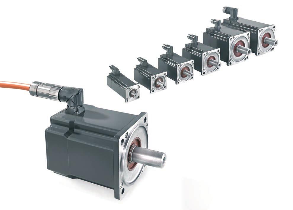
Synchronous Servomotors AM8000 & AM8500
|
|
|
- Ella Goodwin
- 6 years ago
- Views:
Transcription

1 Documentation Version: Date:
2
3 Table of contents Table of contents 1 Foreword Notes on the documentation Documentation Issue Status Appropriate use Guidelines and Standards EC declaration of conformity Safety Safety instructions Special safety instructions for AM8000 and Handling Transport Packaging Storage Maintenance / Cleaning Disposal Product identification AM8000 and, scope of supply AM8000 and nameplate Type key AM8000 and Technical description Design of the motors General technical data Power derating Standard features Style Shaft end, A-side Flange Protection class Overtemperature protection Insulation material class Vibration class Vibrations and shocks Connection technology Feedback System Holding brake Pole number Options Selection criteria Transport, assembly and disassembly Mechanical installation Important notes Flange mounts Electrical installation Important notes
4 Table of contents 8.2 Connection of motors with preassembled cables AX5000 connection diagram for motors with OCT and itec-plug AX5000 connection diagram for motors with OCT-Feedback AX5000 connection diagram for motors with OCT-Feedback AX5000 connection diagram for motors with OCT-Feedback AX5000 connection diagram for motors with OCT-Feedback AX5000 connection diagram for motors with resolver and ytec-plug AX5000 connection diagram for motors with resolver AX5000 connection diagram for motors with resolver AX5000 connection diagram for motors with resolver AX5000 connection diagram for motors with resolver AX5000 connection diagram for motors with resolver AX5000 connection diagram for motors with Hiperface Comissioning Guide for commissioning Troubleshooting Technical data AM801x Dimensional drawing AM801x Radial / axial forces at the shaft end Characteristic torque / speed curves AM802x Dimensional drawing AM802x Radial / axial forces at the shaft end Characteristic torque / speed curves AM803x and AM853x Dimensional drawing AM803x and AM853x Radial / axial forces at the shaft end Characteristic torque / speed curves AM804x and AM854x Dimensional drawing AM804x and AM854x Radial / axial forces at the shaft end Characteristic torque / speed curves AM805x and AM855x Dimensional drawing AM805x and AM855x Dimensional drawing AM805x-9000 and AM855x Radial / axial forces at the shaft end Characteristic torque / speed curves AM806x and AM856x Dimensional drawing AM806x and AM856x Dimensional drawing AM8063 and AM8563 with R winding Radial / axial forces at the shaft end Characteristic torque / speed curves AM807x Dimensional drawing AM807x Dimensional drawing AM807x (OCT) Dimensional drawing AM8074 (Terminal box) Radial / axial forces at the shaft end Characteristic torque / speed curves Appendix
5 Table of contents 11.1 Support and Service
6 Table of contents 6

7 Foreword 1 Foreword 1.1 Notes on the documentation This description is only intended for the use of trained specialists in control and automation engineering who are familiar with the applicable national standards. It is essential that the documentation and the following notes and explanations are followed when installing and commissioning the components. It is the duty of the technical personnel to use the documentation published at the respective time of each installation and commissioning. The responsible staff must ensure that the application or use of the products described satisfy all the requirements for safety, including all the relevant laws, regulations, guidelines and standards. Disclaimer The documentation has been prepared with care. The products described are, however, constantly under development. We reserve the right to revise and change the documentation at any time and without prior announcement. No claims for the modification of products that have already been supplied may be made on the basis of the data, diagrams and descriptions in this documentation. Trademarks Beckhoff, TwinCAT, EtherCAT, Safety over EtherCAT, TwinSAFE, XFC and XTS are registered trademarks of and licensed by Beckhoff Automation GmbH. Other designations used in this publication may be trademarks whose use by third parties for their own purposes could violate the rights of the owners. Patent Pending The EtherCAT Technology is covered, including but not limited to the following patent applications and patents: EP , EP , DE , DE with corresponding applications or registrations in various other countries. The TwinCAT Technology is covered, including but not limited to the following patent applications and patents: EP , US with corresponding applications or registrations in various other countries. EtherCAT is registered trademark and patented technology, licensed by Beckhoff Automation GmbH, Germany Copyright Beckhoff Automation GmbH & Co. KG, Germany. The reproduction, distribution and utilization of this document as well as the communication of its contents to others without express authorization are prohibited. Offenders will be held liable for the payment of damages. All rights reserved in the event of the grant of a patent, utility model or design. 7
8 Foreword 1.2 Documentation Issue Status Issue Notice 3.4 Chapter update: EC declaration of conformity 2.1; Technical drawing AM806x and AM856x Chapter update: 1.0; 2.1; 3.0; 4.5; 5.3; ; ; ; New chapter: 8.5; 8.10; Deleted chapter: Documented motors 3.2 Chapter update: 5.2; Chapter update: 5.3; Chapter update: ; Chapter update 8.3; 8.4; 8.5; 8.6; 8.7; 8.8; 8.9; 8.10; 8.11; 8.12; 10.1; 10.2; 10.3; 10.4; 10.5; 10.6; Chapter update 2.1; 5.3; ; Chapter update 8.2; 10.1; 10.2; 10.3; 10.4; 10.5; 10.6; Chapter update ; ; ; ; ; ; Chapter update Documented motors AM8000 and ; 3.2; 8.1; 9.1; ; 10; 10.1; 10.2; 10.3; 10.4; 10.5; 10.6; 10.7 New chapter Graphic resolution adjusted 2.3 Chapter update 2.1; 3.2; 4.2; 4.4; 5.2; 5.3; 6.3.2; 6.3.3; 6.3.4; 6.3.5; ; 8.6; 10.2; 10.3; 10.4; 10.5; 10.6; 10.7 New chapter 10.1; ; Chapter update 6.3.5; ; ; 10.6; 10.7 New chapter Chapter update 8.4; General update (Series added) 1.2 Chapter update New chapter Chapter update ; 8.3; 8.4; 8.5; First issue 8
9 Foreword 1.3 Appropriate use Synchronous servomotors of the AM8000 and series are designed as drives for handling equipment, textile machines, machine tools, packaging machines and similar machines with demanding requirements in terms of dynamics. The motors of the AM8000 and series are exclusively intended for speed- and/or torque-controlled operation via digital servo drives from Beckhoff Automation GmbH & Co. KG. The thermal protection contact incorporated in the motor windings must be analysed and monitored. CAUTION WARNING Note Danger for persons, the environment or equipment The motors are operated in the drive system in conjunction with Beckhoff servo drives. Please observe the entire documentation which consists of: AM8000 and documentation (this manual) Complete documentation (online and paper) for Beckhoff servo drives available at Complete machine documentation (provided by the machine manufactor) Caution Risk of injury! Electronic equipment is not fail-safe. The machine manufacturer is responsible for ensuring that the connected motors and the machine are brought into a safe state in the event of a fault in the drive system. Special safety instructions for AM8000 and! The general safety instructions [} 11] and the special safety instructions for AM8000 and [} 12] sections are also essential. Read carefully! The servomotors from the AM8000 and series are exclusively designed for installation as components in electrical systems or machines and may only be operated as integrated components of the system or machine. The motors may only be operated under the ambient conditions defined in this documentation. 9
10 Guidelines and Standards 2 Guidelines and Standards CAUTION Danger for persons Servomotors of the AM8000 and series are not classified as products within the meaning of the EC Machinery Directive. Operation of the servomotors in machines or systems is only permitted once the machine or system manufacturers has provided evidence of EC conformity of the complete machine or system. 2.1 EC declaration of conformity We, Beckhoff Automation GmbH & Co. KG Hülshorstweg Verl Germany Hereby declare, under our sole responsibility, that the product range Motor series AM8000 (Types AM801x, AM802x, AM803x, AM804x, AM805x, AM806x, AM807x) Motor series (Types AM853x, AM854x, AM855x, AM856x) The components mentioned herein have been developed, designed and manufactured in accordance with the Low Voltage Directive 2006/95/EC (until ) and 2014/35/EU (from ) as well as EMC Directive 2004/108/EC (until ) and 2014/30/EU (from ). The following standards have been used: Product Standard: EN :2004+A1:2012 Adjustable speed electrical power drive systems EMC requirements and specific test methods Product Standard: EN :2010+Corr.:2010 Rotating electrical machines Rating and performance Attachment of the CE mark: 2016 Issued by: Management H. Beckhoff Verl,
11 Safety 3 Safety 3.1 Safety instructions Safety regulations Please note the following safety instructions and explanations! Product-specific safety instructions can be found on following pages or in the areas mounting, wiring, commissioning etc. Exclusion of liability All the components are supplied in particular hardware and software configurations appropriate for the application. Modifications to hardware or software configurations other than those described in the documentation are not permitted, and nullify the liability of Beckhoff Automation GmbH & Co. KG. Personnel qualification This description is only intended for trained specialists in control, automation and drive engineering who are familiar with the applicable national standards. Description of symbols In this documentation the following symbols are used with an accompanying safety instruction or note. The safety instructions must be read carefully and followed without fail! Serious risk of injury! Failure to follow the safety instructions associated with this symbol directly endangers the life and health of persons. DANGER Risk of injury! Failure to follow the safety instructions associated with this symbol endangers the life and health of persons. WARNING Personal injuries! Failure to follow the safety instructions associated with this symbol can lead to injuries to persons. CAUTION Damage to the environment or devices Failure to follow the instructions associated with this symbol can lead to damage to the environment or equipment. Attention Tip or pointer This symbol indicates information that contributes to better understanding. Note UL pointer This symbol indicates important information about the UL-compliant. 11
12 Safety 3.2 Special safety instructions for AM8000 and The safety instructions are designed to avert danger and must be followed during installation, commissioning, production, troubleshooting, maintenance and trial or test assemblies. The servomotors of the AM8000 and series are not designed for stand-alone operation and are always installed in a machine or system. After installation the additional documentation and safety instructions provided by the machine manufacturer must be read and followed. WARNING WARNING Attention Serious risk of injury through high electrical voltage! Never open the servomotor when it is live. The measured voltage between terminals U, V and W must have dropped below 50 V. Opening the devices would invalidate any warranty and liability claims against Beckhoff Automation GmbH. Negligent, improper handling of the servomotor and bypassing of the safety devices can lead to personal injury or death through electric shock. Ensure that the protective conductor is connected properly. The machine manufacturer must prepare a hazard analysis for the machine, and must take appropriate measures to ensure that unexpected movements cannot lead to injury to persons or to material damage. Power leads may be live, even if the motor is not running. Never undo the electrical connections to the motor when it is live. Under unfavourable conditions arcing may occur, resulting in injury and damage to contacts. Disconnect the servomotor from the servo drive and secure it against reconnection before working on electrical parts with a voltage > 50 V. Due to the DC link capacitors dangerous voltage (> 890V DC ) may persist at the DC link contacts ZK+ and ZK- (DC+ and DC-) and RB+ and RB- after the servo drive has been disconnected from the mains supply. After disconnecting the servo drive wait at AX AX5125 and AX520x; 5 minutes, at AX5140/AX5160/AX5172; 15 minutes, at AX5190/AX5191; 30 minutes and at AX5192/AX5193; 45 minutes and measure the voltage at the DC link contacts ZK+ and ZK- (DC+ and DC-). The device is safe once the voltage has fallen below 50 V. Serious risk of injury through hot surfaces! The surface temperature may exceed 100 C, resulting in a risk of burns. Avoid touching the housing during or shortly after operation. Leave the servomotor to cool down for at least 15 minutes after it is switched off. Use a thermometer to check whether the surface has cooled down sufficiently. Danger for persons Carefully read this manual before using the servomotor thoroughly, paying particular attention to the safety instructions. In the event of any uncertainties please notify your sales office immediately and refrain from working on the servomotor. Only well trained, qualified electricians with sound knowledge of drive equipment may work on the device. During installation it is essential to ensure that the specified ventilation clearances and climatic conditions are adhered to. Further information can be found in the Technical data and Mechanical installation sections. If a servomotor is installed in a machine it must not be commissioned until proof of compliance of the machine with the latest version of the EC Machinery Directive has been provided. This includes all relevant harmonised standards and regulations required for implementation of this Directive in national legislation. 12
13 Handling 4 Handling 4.1 Transport Climate category: 2K3 according to EN Transport temperature: -25 C C, max. fluctuation 20 K/hour Transport humidity: relative humidity 5% - 95%, non-condensing The servomotor may only be transported by qualified personnel and in the manufaturer s original recyclable packaging. Avoid hard impacts, particularly at the shaft end. If the packaging is damaged, check the motor for visible damage. Inform the transport company and, if necessary, the manufacturer. 4.2 Packaging Cardboard packaging Motor type Max. stacking height AM801x 10 AM802x 10 AM803x / AM853x 6 AM804x / AM854x 6 AM805x / AM855x 5 AM806x / AM856x 2 AM807x Storage Climate category: 2K3 according to EN Storage temperature: -25 C C, max. fluctuation 20 K/hour Air humidity: relative humidity 5% - 95%, non-condensing Max. stacking height: see table Packaging Storage time: without limitation Store only in the manufacturer s original recyclable packaging. 13
14 Handling 4.4 Maintenance / Cleaning Maintenance and cleaning only by qualified personnel. The ball bearings have a grease filling with a service life of 30,000 hours under normal operating conditions. The bearings should be replaced after 30,000 hours of operation under rated conditions. Check the motor for bearing noise every 2,500 operating hours or once per year. If any noises are heard, stop the operation of the motor. The bearings must be replaced. In motors with optional shaft seal ring the ring must be lubricated every 5,000 hours. We recommend Mobilgrease TM FM 222 from Mobil. Opening the motor invalidates the warranty. Clean the housing with isopropanol or similar. Attention Destruction of the servomotor Never immerse or spray the servomotor. 4.5 Disposal In accordance with the WEEE 2012/19/EU Directives we take old devices and accessories back for professional disposal, provided the transport costs are taken over by the sender. Send the devices with the note For disposal to: Beckhoff Automation GmbH & Co. KG Huelshorstweg 20 D Verl 14
15 Product identification 5 Product identification 5.1 AM8000 and, scope of supply Please check that the delivery includes the following items: Motor from the AM8000 or series Leaflet (short info) 5.2 AM8000 and nameplate Item number Explanation 1 Servomotor type 2 Protection class 3 Thermo contact type 4 Country of manufacture 5 Serial number 6 Brake type 7 UL certification for USA / CAN 8 Insulation class 9 Rated output 10 Nominal speed 11 Rated voltage 12 Standstill current 13 Standstill torque 15
16 Product identification 5.3 Type key AM8000 and This matrix should explain the motor flange sizes related to a gearbox mounting. Motor sizes, named in the same line use the same adapter unit for a gearbox coupling. Beckhoff Flange size AM3000 AM3100 AM3500 AM8000 AM8100 F1 AM301x AM311x - AM801x AM811x - F2 AM302x - - AM802x AM812x - Exception - AM312x F3 AM303x - - AM803x AM813x AM853x F4 AM304x - AM354x AM804x - AM854x F AM805x - AM855x Exception AM305x - AM355x AM805x-xxxx F6 AM306x - AM356x AM806x - AM856x F7 AM307x - - AM807x - - Exception AM308x
17 Technical description 6 Technical description 6.1 Design of the motors The synchronous servomotors of the AM8000 and series are brushless three-phase motors for demanding servo-applications. In conjunction with our digital servo drives they are particularly suitable for positioning tasks in industrial robots, machine tools, transfer lines etc. with demanding requirements in terms of dynamics and stability. The servomotors are equipped with permanent magnets in the rotor. This advanced neodymium magnetic material makes a significant contribution to the motors exceptional dynamic properties. A three-phase winding is housed in the stator, and this is powered by the servo drive. The motor has no brushes, the commutation being implemented electronically in the servo drive. The winding temperature is measured with a KTY PTC silicon sensor and monitored in the servo drive. The motors are available with or without built-in holding brake. The brake cannot be retrofitted. The motors have a matt black powder coating (RAL 7016). The finish is not resistant against solvents (e.g. trichloroethylene, thinners or similar). 6.2 General technical data Climate category 3K3 according to EN Ambient temperature (at rated values) Permissible humidity (at rated values) C for site altitudes up to 1000 m amsl It is vital to consult our applications department for ambient temperatures above 40 C and encapsulated installation of the motors. 95% relative humidity, non-condensing Power derating (currents and torques) For site altitudes above 1000 m amsl and 40 C 6% at 2000m amsl 17% at 3000m amsl 30% at 4000m amsl 55% at 5000m amsl No derating for site altitudes above 1000m amsl with temperature reduction of 10K / 1000m Ball bearing service life operating hours Technical data see Section 10 Storage and transport data see Section 4 17
18 Technical description 6.3 Power derating Ambient temperature f T = Temperature utilisation factor t A = Ambient temperature in C Calculation of the power data when exceeding the specified temperature limit > 40 C up to 55 C: M 0_red = M 0 x f T Installation altitude f H = Altitude utilisation factor h = Altitude in metres Calculation of the power data when exceeding the specified installation altitude > 1000 m up to 3000 m: M 0_red = M 0 x f H Ambient temperature and installation altitude Calculation of the power data when exceeding the specified limits: Ambient temperature > 40 C and installation altitude > 1000 m. M 0_red = M 0 x f T x f H 18
 must be removed from shaft when motor is mounted according to IM V3.")
19 Technical description 6.4 Standard features Style The basic style for the AM8000 and synchronous servomotors is IM B5 according to DIN EN The permitted mounting positions are specified in the technical data. Attention Motor damage To avoid liquid entry damaging the motor, fluids (i.e. used for cleaning purposes) must be removed from shaft when motor is mounted according to IM V Shaft end, A-side Load transmission occurs force locked (zero-play) with a clutch on the cylindric end of the shaft A or optionally by keyed connection with feather key groove according to DIN The lifecycle of the bearings is operating hours. Radial force If the motor drive via pinions or toothed belts, then high radial forces will occur. The permissible values at the shaft end, depending on the speed, may be read from the diagrams in the Section 10. Please use the force calculation program Beckhoff AM8000-Motors Radial forces, life cycle available from our website for exact calculation of the radial forces. Axial force Axial forces arise when assembling pinions or pulleys on the shaft and using angular gearheads, for example. Please use the force calculation program Beckhoff AM8000-Motors Radial forces, life cycle available from our website for exact calculation of the radial forces. Coupling Double-coned collets, possibly in association with metal bellows couplings, have proven themselves as excellent, zero backlash coupling elements Flange Flange dimensions according to IEC standard, fit j6 (h7 at AM801x ), accuracy according to DIN Tolerance class : N 19
20 Technical description Protection class Standard version - housing IP65 (IP54 at AM801x ) Standard version shaft feedthrough IP54 Shaft feedthrough with shaft sealing ring IP Overtemperature protection The standard version of each motor (not AM801x) is fitted with a KTY Provided our preassembled motor cable is used, the KTY is integrated into the monitoring system of the digital servo amplifiers. Please configure the servo drive such that a motor temperature warning is issued at 100 C and the motor is switched off at 140 C Insulation material class The motors conform to insulation material class F according to IEC (UL 1446 class F) Vibration class The motors are made to vibration class A according to DIN EN For a speed range of rpm and a shaft centre height between mm, this means that the actual value of the permitted vibration severity is 1.6 mm/s. Speed [rpm] Max. rel. vibration displacement [µm] <= > Max. run-out [µm] Vibrations and shocks OCT and Multiturn: Vibration according to EN g / Hz Shocks according to EN g / 6 ms Connection technology The motors are fitted with rotatable, angular connectors for the power supply and the feedback signals (only resolver). The mating connectors are not included in the scope of supply. We can supply preassembled feedback (only resolver + Hiperface at AM807x) and power cables. 20
21 Technical description Feedback System Feedbacksystem Resolution System accuracy Comment OCT, Singleturn OCT, Multiturn 18 Bit ± 120 Angle sec. Ca. 0,03 Standard: AM801x AM8x6x Hiperface 18 Bit ± 120 Angle sec. ca. 0,03 Standard: AM807x OCT, Singleturn OCT, Multiturn 23 Bit ± 30 Angle sec. ca. 0,005 From Firmware v2.10 Resolver 14 Bit ± 600 Angle sec. ca. 0,17 Option Note Feedback exchange The feedback system installed can only be replaced with an identical system. Retrofitting a different system is not possible Holding brake WARNING Serious risk of injury! The holding brake is not personal safety. If the brake is released then the rotor can be moved without a remanent torque! The motors are optionally available with an in built holding brake. The permanent magnet brake blocks the rotor in de-energised state. The holding brakes are designed as standstill brakes and are not suited for repeated operational braking. The holding brakes can be controlled directly by the servo drive (no personal safety!). The brake voltage is then switched off in the servo drive no additional wiring is required. If the holding brake is not controlled directly by the servo drive, additional circuitry (e.g. R/C or diode) is required. Consult our applications department beforehand. The maximum number of brake cycles is 10 million. Note Motor length The motor length depends on the built-in holding brake, among other factors. It is not possible to fit one at a later date Pole number Motor Poles Motor Poles AM801x 6 AM805x, AM855x 8 AM802x 6 AM806x, AM856x 10 AM803x, AM853x 8 AM807x 10 AM804x, AM854x 8 21
22 Technical description 6.5 Options Holding brake The holding brake is integrated in the motor. It increases the motor length and the rotor moment of inertia. Radial shaft-sealing ring Radial shaft-sealing ring (FKM) for sealing against splash water. This increases the protection class of the shaft busching to IP65. Father key The motors are available with feather key groove and fitted feather key according to DIN The rotor is balanced with half a feather key. Resolver This model features a different feedback system in place of the OCT or the hiperface. Installation options and reduction of rated values With the exception of the sealing ring, the options cannot be retrofitted. Note The option sealing ring can lead to a reduction oft he rated data. 6.6 Selection criteria The three-phase servomotors are designed for operation with the servo drive. Both together form a speed or torque control loop. The main selection criteria are: Standstill torque Maximal torque Rated speed at rated supply voltage Moment of inertia of motor and load Effective torque (calculated) M0 [Nm] Mmax [Nm] nn [min-1] J [kgcm²] Mrms [Nm] The static load and the dynamic load (acceleration/braking) must be taken into account in the calculation of the required motors and the servo drive. Formulas and calculation example are available from our applications department on request. 22


23 Technical description 6.7 Transport, assembly and disassembly CAUTION Personal injuries! Protective clothing, protective gloves and safety boots must be worn at all times during transport, assembly and disassembly. Do not step under suspended motors. The motors of the AM8x1x to AM8x5x series can be moved without auxiliary equipment. The motors of the AM8x6x series can be moved with loop belts. The motors of the AM807x series are equipped with eyebolts as standard. These eyebolts are suitable for crane hooks. 23
24 Mechanical installation 7 Mechanical installation 7.1 Important notes Motor damage Take care, especially during transport and handling that components are not bent and that insulation clearances are not altered. Attention The site must be free of conductive and aggressive material. For V3-mounting (shaft end upwards), make sure that no liquids can enter the bearings. If an encapsulated assembly is required, please consult our applications department beforehand. Ensure unhindered ventilation of the motors and observe the permissible ambient and flange temperatures. For ambient temperatures above 40 C please consult our applications department beforehand. Servomotors are precision devices.the flange and shaft are especially vulnerable during storage and assembly.it is important to use the locking thread which is provided to tighten up couplings, gear wheels or pulleys and warm up the drive components, where possible.blows or the use of force will lead to damage to the ball bearings, shaft, holding brake and feedback System. Wherever possible, use only backlash-free, frictionally-locking collets or couplings. Ensure correct alignment of the couplings. A displacement will cause unacceptable vibration and the destruction of the ball bearings and the coupling. For toothed belts, it is vital to observe the permissible radial forces. An excessive radial load on the shaft will significantly shorten the life of the Motor. Avoid axial loads on the motor shaft, as far as possible. Axial loading significantly shortens the life of the Motor. Furthermore, it must be ensured that when using a collet, the motor shaft is degreased. In any case, avoid creating a mechanically constrained motor shaft mounting by using a rigid coupling with additional external bearings (e.g. in a gearbox). Take note of the no. of motor poles and the no. of resolver poles and ensure that the correct setting is made in the used servo terminals. An incorrect setting can lead to the destruction of the motor, especially with small Motors. Check compliance the permitted radial and axial loads FR and FA.When using a toothed belt drive, the minimum permitted diameter of the pinion follows from the equation: 24
25 Mechanical installation 7.2 Flange mounts Motor Bore diameter [mm] Cheese head screw DIN EN ISO 4762 (8.8) Tightening torque [Nm] AM801x 4,3 M4x16 3 4,3 AM802x 5,5 M5x16 5,5 5,3 AM8x3x 6,0 M5x16 5,5 5,3 AM8x4x 7,0 M6x20 10,0 6,4 AM8x5x 9,0 M8x25 25,0 8,3 AM8x6x 11,0 M10x30 50,0 10,5 AM807x 13,5 M12x40 85,0 13,0 Plain washer DIN EN ISO
26 Electrical installation 8 Electrical installation 8.1 Important notes DANGER Attention Serious risk of injury through electric shock! Only staffs qualified and trained in electrical engineering are allowed to wire up the motor. Check the assignment of the servo drive and the motor. Compare the rated voltage and the rated current of the devices. Always make sure that the motors are de-energised during assembly and wiring, i.e. no voltage may be switched on for any piece of equipment which is to be connected. Ensure that the control cabinet remains turned off (barrier, warning signs etc.). The individual voltages will only be turned on again during commissioning. Due to the DC link capacitors dangerous voltage (> 890V DC ) may persist at the DC link contacts ZK+ and ZK- (DC+ and DC-) and RB+ and RB- after the servo drive has been disconnected from the mains supply. After disconnecting the servo drive wait at AX AX5125 and AX520x; 5 minutes, at AX5140/AX5160/AX5172; 15 minutes, at AX5190/AX ; minutes and at AX5192/AX5193; 45 minutes and measure the voltage at the DC link contacts ZK+ and ZK- (DC+ and DC-). The device is safe once the voltage has fallen below 50 V. Failure-free operation Ensure that the servo drive and the motor are earthed properly. See below for further information regarding EMC shielding and earthing. Earth the mounting plate and motor housing. Further details of connection types can be found in section 8.2. Only use cables approved by Beckhoff for operating the AM8000 and with the one-cable technology (OCT). Route the power and control cables as separately as possible from one another (separation > 20 cm). This will improve the immunity of the system to electromagnetic interference. If a motor power cable is used which includes integral brake control leads, then these brake control leads must be shielded. The shielding must be connected at both ends (see Section ). Install all cables carrying a heavy current with an adequate cross-section, as per EN The recommended cross-section can be found in the technical data of the cables. Wiring: ð Connect the feedback cable ð Connect the motor cables ð Connect shields to shield terminals or EMC connectors at both ends ð Connect the motor holding brake Attention HF interference The ground symbol, which you will find in the wiring diagrams, indicates that you must provide an electrical connection, with as large a surface area as possible, between the unit indicated and the mounting plate in the control cabinet. This connection is to suppress HF interference and must not be confused with the PE (protective earth) symbol (protective measure according to EN 60204). Follow the instructions in the circuit diagrams in Sections 8.3 to

27 Electrical installation Note Motor cable length at servo drives up to 25 A Motors with max. 400 V rated voltage: If the length of the motor cable is 25 m, then a motor choke is required for each motor. Motors with max. 480 V rated voltage: If the length of the motor cable is > 20 m, then a motor choke is required for each motor. The control cabinet should then have adequate space for motor chokes. In exceptional cases (sensitive sensors etc.) it can be necessary to use a motor choke even for motor cable lengths < 25 / 20 m. The motor choke is supplied with a connection cable. Do not alter the configuration (cable length, cross-section etc.). 8.2 Connection of motors with preassembled cables Beckhoff offers preassembled motor and feedback cables for safe, faster and flawless installation of the motors. Beckhoff cables have been tested with regard to the materials, shielding and connectors used. They ensure proper functioning and compliance with statutory regulations such as EMC, UL etc. The use of other cables may lead to unexpected interference and invalidate the warranty. Carry out the wiring in accordance with the valid standards and regulations. Only use our preassembled shielded cables for the power and feedback connections. Connect up the shielding according to the wiring diagrams in sections 8.3 to Incorrectly installed shielding inevitably leads to EMC interference. Detailed specifications of the cables can be found on our homepage under Download Documentation Drive Technology Cables. 27
. The itec connector (item 1) should fully enclose the silver-colored housing of the power box (item 2). Note!")
 (white marking point on the itec connector, recessed")


28 Electrical installation Power box of the servomotor with itec connector Align the itec connector (item 1) with the power box of the servomotor (item 2). The itec connector (item 1) should fully enclose the silver-colored housing of the power box (item 2). Note!: Avoid contamination of or damage to the poles and the interior of the box and the connector! When connecting the two components, make sure that both marking points (item 3) (white marking point on the itec connector, recessed grey marking point on the power box) face each other. Now push the itec connector onto the power box of the servomotor. This procedure causes the itec connector to turn. After the rotary motion the itec connector engages on the power box of the servomotor. Note!: When the connector engages on the power box, a click sound can be heard. This indicates that the components were installed correctly. If the itec connector cannot easily be pushed onto the power box and made to engage, manually turn the white marking point into the correct position (see Fig. 2 and 3). 28
 can turn freely. Press the two plug connectors together until the locking point is reached.")
29 Electrical installation itec extension cable Connecting the plug connection Align the two plug connector (1) and (2) such that the white marking point (3) and the area (4) line up. Push the two plug connectors together in the direction of the arrow. Ensure that the black locking ring (5) can turn freely. Press the two plug connectors together until the locking point is reached. Note!: When the connector engages, a click sound can be heard. This indicates that the components were installed correctly. If the connector does not engage automatically, manually turn the white marking point into the correct position. To disconnect the plug connection Hold the plug connector (2), turn the black locking ring (1) downwards in the direction of the arrow and hold it in this position. Now pull the plug connector (2) apart to the left in the direction of the arrow. 29

30 Electrical installation 8.3 AX5000 connection diagram for motors with OCT and itec-plug Servo drives: AX5101 AX5112 and AX52xx Motors: AM801x AM803x and AM853x 30
31 Electrical installation 8.4 AX5000 connection diagram for motors with OCT- Feedback Servo drives: AX5101 AX5112 and AX52xx Motors: AM804x AM806x and AM854x AM856x (until P winding) 31

32 Electrical installation 8.5 AX5000 connection diagram for motors with OCT- Feedback Servo drives: AX AX5125 Motors: AM804x AM806x and AM854x AM856x (until P winding) 32
33 Electrical installation 8.6 AX5000 connection diagram for motors with OCT- Feedback Servo drive: AX5125 Motors: AM806x, AM856x (from Q-winding) and AM807x 33

34 Electrical installation 8.7 AX5000 connection diagram for motors with OCT- Feedback Servo drive: AX5140 Motors: AM806x, AM856x (from Q-winding) and AM807x 34

35 Electrical installation 8.8 AX5000 connection diagram for motors with resolver and ytec-plug Servo drives: AX5101 AX5112 and AX52xx Motors: AM802x AM803x and AM853x 35
36 Electrical installation 8.9 AX5000 connection diagram for motors with resolver Servo drives: AX5101 AX5112 and AX52xx Motors: AM804x AM806x and AM854x AM856x (until P-winding) 36

37 Electrical installation 8.10 AX5000 connection diagram for motors with resolver Servo drives: AX5118 AX5125 Motors: AM804x AM806x and AM854x AM856x (until P-winding) 37

38 Electrical installation 8.11 AX5000 connection diagram for motors with resolver Servo drive: AX5125 Motors: AM806x, AM856x (from Q-winding) and AM807x 38

39 Electrical installation 8.12 AX5000 connection diagram for motors with resolver Servo drive: AX5140 Motors: AM806x, AM856x (from Q-Winding) and AM807x 39
40 Electrical installation 8.13 AX5000 connection diagram for motors with resolver Servo drives: AX5160 and AX5172 Motors: AM806x, AM856x (from Q-winding) and AM807x 40
41 Electrical installation 8.14 AX5000 connection diagram for motors with Hiperface Servo drives: AX5160 and AX5172 Motors: AM806x, AM856x (from Q-winding) and AM807x 41
42 Comissioning 9 Comissioning 9.1 Important notes DANGER Serious risk of injury! Only specialist personnel with extensive knowledge in the areas of electrical engineering / drive technology are allowed to install and commission the equipment. Check that all live connection points are protected against accidental contact. Dangerous voltages can occur, up to 890 V DC. Due to the DC link capacitors dangerous voltage (> 890 V DC ) may persist at the DC link contacts ZK+ and ZK- (DC+ and DC-) and RB+ and RB- after the servo drive has been disconnected from the mains supply. After disconnecting the servo drive wait at AX AX5125 and AX520x; 5 minutes, at AX5140/AX5160/AX5172; 15 minutes, at AX5190/AX5191; 30 minutes and at AX5192/AX5193; 45 minutes and measure the voltage at the DC link contacts ZK+ and ZK- (DC+ and DC-). The device is safe once the voltage has fallen below 50 V. The surface temperature of the motor can exceed 100 C in operation. Check (measure) the temperature of the motor. Wait until the motor has cooled down below 40 C before touching it. Make sure that, even if the drive starts to move unintentionally, no danger can result for personnel or machinery. 9.2 Guide for commissioning The procedure for commissioning is describe as an example. A different method may be appropriate or necessary, depending on the application of the equipment. Check the assembly and orientation of the motor. Check the drive components (coupling, gear unit, pulley) for the correct seating and setting (observe the permissible radial and axial forces). Check the writing and connections to the motor and the servo drive. Check that the earthing is correct. Test the function of the holding brake, if used (apply 24V DC. the brake must be released). Check whether the rotor of the motor revolves freely (release the brake, if necessary). Listen out for grinding noises. Check that all the required measures against accidental contact with live and moving parts have been carried out. Carry out any further tests which are specifically required for your system. Now commission the drive according to the commissioning instructions for the servo drive. In multi-axis systems, individually commission each drive unit (servo drive/motor(s)). 42
43 Comissioning 9.3 Troubleshooting The following table is to be seen as a First Aid box. There can be a large number of different reasons for a fault, depending on the particular conditions in your system. The fault causes described below are mostly those which, directly influence the motor. Peculiarities which show up in the control behaviour can usually be traced back to an error in the parameterization of the servo drive. The documentation for the servo drive and the commissioning software provides information of these matters. For multi-axis systems there may be further hidden reasons for faults. Our application department can give you further help with your problems. Fault Possible cause Measures to remove the cause of the fault Motor doesn t rotate Servo drive not enabled Break in setpoint lead Motor phases in wrong sequence Brake not released Drive is mechanically blocked Supply ENABLE signal Check setpoint lead Correct the phase sequence Check brake control Check mechanism Motor runs away Motor phases in wrong sequence Correct the phase sequence Motor oscillates Error message: brake Error message: output stage fault Error-message: feedback Break in the shielding of the feedback cable Amplification to high Short-circuit in the supply voltage lead to the motor holding brake Faulty motor holding brake Motor cable has short circuit or earth leakage Motor has short circuit or earth leakage Connector is not properly plugged in Break in cable, cable crushed or similar Error-message: motor temperature Motor thermostat has switched Loose connector or break in cable Brake does not grip Required holding torque too high Brake faulty Replace feedback cable Use motor default values Remove the short circuit Replace motor Replace motor cable Replace motor Check connector Check cables Wait until the motor has cooled down. Then investigate why the motor becomes so hot. Check connector, replace cable if necessary Check the dimensioning Replace motor 43
44 Technical data 10 Technical data All data, excluding the voltage constant, valid for 40 C ambient temperature and 100 K overtemperature of the winding. The data can have a tolerance of +/- 10%. If a gear unit is attached the power may be reduced by up to 20%. This loss in performance has thermal reasons, since a gear unit that is subject to warming is installed at the motor flange intended for heat dissipation. Term definitions Standstill torque M0 [Nm] The standstill torque can be maintained indefinitely at a speed n < 100 rpm and rated ambient conditions. Rated torque Mn [Nm] The rated torque is produced when the motor is drawing the rated current at the rated speed. The rated torque can be produced indefinitely at the rated speed in continuous operation (S1). Standstill current I0rms [A] The standstill current ist he effective sinusoidal current which the motor draws at n < 100 rpm to produce the standstill torque. Peak current (pulse current) I0max [A] The peak current (effective sinusoidal value) is approximately equivalent to 5-times the rated standstill current (3-times at AM806x, AM807x and AM856x). The configured peak current of the servo drive used must be smaller. Torque constant KTrms [Nm/A] The torque constant defines how much torque in Nm is produced by the motor with standstill current. The relationship is M0=I0 x KT. Voltage constant KErms [mvmin] The voltage constant defines the induced motor EMF, as an effective sinusoidal value between two terminals, at 20 C per 1000 rpm. Rotor moment of inertia J [kgcm²] The constant J is a measure of the acceleration capability of the motor. For instance, at l0 the acceleration time tb from 0 to 3000 rpm is given as: with M0 in Nm and J in kgcm2 Thermal time constant tth [min] The constant tth defines the time for the cold motor, under a load of l0 to heat up to an overtemperature of 0,63 x 100 Kelvin. This temperature rise happens in a much shorter time when the motor is loaded with the peak current. Release delay time tbrh [ms] / Application delay time tbrl [ms] of the brake These constants define the response times of the holding brake when operated with the rated voltage from the servo drive. Winding inductance L [mh] The winding inductance is an specification of the motor inductance. This is get as an average value on two energized phases at 1 KHz. The saturation of the motor must be take into account. 44
45 Technical data 10.1 AM801x Technical data Symbol [Unit] AM80xx Electrical data 11B 12C 13D Standstill torque* M 0 [Nm] 0,20 0,38 0,52 Standstill current I orms [A] 0,76 1,30 1,65 Max. mechanical speed N max [min -1 ] Max. rated mains voltage U N [VAC] 250 U N = 115V Rated speed Nn [min-1] Rated torque* M n [Nm] 0,19 0,35 0,49 Rated output P n [kw] 0,07 0,15 0,18 U N = 230V Rated speed Nn [min-1] Connector plug Rated torque* M n [Nm] 0,18 0,33 0,45 Rated output P n [kw] 0,15 0,28 0,38 Peak current I 0max [A] 2,30 4,55 5,90 Peak torque M 0max [Nm] 0,68 1,37 2,04 Torque constant K Trms [Nm/A] 0,263 0,292 0,315 Voltage constant K Erms [mvmin] 19 19,2 22,7 Winding resistance Ph-Ph Winding inductance Ph-Ph** *reference flange aluminium 130 mm x 230 mm x 10 mm. **measured at 1kHz. The installation of a shaft seal ring leads to a reduction of the rated values. R 20 [Ω] 34,50 15,00 11,50 L [mh] 21,00 10,50 9,00 Mechanical data AM8011 AM8012 AM8013 Rotor moment of inertia (without brake) J [kgcm 2 ] 0,0339 0,0527 0,0715 Rotor moment of inertia (with brake) J [kgcm 2 ] 0,0566 0,0754 0,0942 Pole number Static friction torque M R [Nm] 0,0009 0,0018 0,0027 Thermal time constant t TH [min] Weight (without brake) G [kg] 0,55 0,64 0,79 Weight (with brake) G [kg] 0,74 0,86 0,98 Permitted radial force at shaft end F R [N] see Permitted axial force F A [N] itec Data for optional brake Data Symbol [Unit] AM801x Holding torque at 120 C M BR [Nm] 0,6 Supply voltage U BR [V DC ] % Electrical power P BR [W] 10 Current I on [A] 0,3 Release delay time t BRH [ms] 14 Application delay time t BRL [ms] 8 45

46 Technical data Dimensional drawing AM801x Radial / axial forces at the shaft end Characteristic torque / speed curves Characteristic torque / speed curves can be found on the Beckhoff-website under Motion 46
47 Technical data 10.2 AM802x Technical data Electrical data Symbol [Unit] AM80xx 21B 21D 22D 22E 23E 23F Standstill torque* M 0 [Nm] 0,50 0,50 0,80 0,80 1,20 1,20 Standstill current I orms [A] 0,85 1,60 1,50 2,44 2,20 3,40 Max. mechanical speed N max [min -1 ] Max. rated mains voltage U N [VAC] 480 U N = 115V Rated speed Nn [min-1] Rated torque* M n [Nm] 0,50 0,50 0,78 0,76 1,15 1,16 Rated output P n [kw] 0,08 0,18 0,16 0,32 0,24 0,43 U N = 230V Rated speed Nn [min-1] Rated torque* M n [Nm] 0,50 0,50 0,75 0,70 1,10 1,00 Rated output P n [kw] 0,21 0,42 0,35 0,59 0,52 0,84 U N = 400V Rated speed Nn [min-1] Rated torque* M n [Nm] 0,50 0,50 0,70 0,65 1,00 0,90 Rated output P n [kw] 0,42 0,47 0,59 0,61 0,84 0,85 U N = 480V Rated speed Nn [min-1] Connector plug Rated torque* M n [Nm] 0,50 0,50 0,65 0,65 0,90 0,90 Rated output P n [kw] 0,47 0,47 0,61 0,61 0,85 0,85 Peak current I 0max [A] 4,90 8,60 7,70 12,60 11,40 17,70 Peak torque M 0max [Nm] 2,68 2,67 4,18 4,18 6,36 6,37 Torque constant K Trms [Nm/A] 0,588 0,313 0,533 0,328 0,545 0,353 Voltage constant K Erms [mvmin] Winding resistance Ph-Ph Winding inductance Ph-Ph** *reference flange aluminium 130 mm x 230 mm x 10 mm. **measured at 1kHz. The installation of a shaft seal ring leads to a reduction of the rated values. R 20 [Ω] 39,40 12,80 13,20 5,10 8,50 3,60 L [mh] 67,0 21,6 30,1 11,2 20,8 8,7 Mechanical data AM8021 AM8022 AM8023 Rotor moment of inertia (without brake) J [kgcm 2 ] 0,139 0,258 0,378 Rotor moment of inertia (with brake) J [kgcm 2 ] 0,208 0,328 0,448 Pole number Static friction torque M R [Nm] 0,002 0,004 0,006 Thermal time constant t TH [min] Weight (without brake) G [kg] 1,00 1,30 1,70 Weight (with brake) G [kg] 1,16 1,66 1,96 Permitted radial force at shaft end F R [N] see Permitted axial force F A [N] itec Data for optional brake Data Symbol [Unit] AM802x Holding torque at 120 C M BR [Nm] 2,0 Supply voltage U BR [V DC ] % Electrical power P BR [W] 10 Current I on [A] 0,3 Release delay time t BRH [ms] 25 Application delay time t BRL [ms] 8 47
48 Technical data Dimensional drawing AM802x Radial / axial forces at the shaft end Characteristic torque / speed curves Characteristic torque / speed curves can be found on the Beckhoff-website under Motion 48
49 Technical data 10.3 AM803x and AM853x Technical data Electrical data Symbol [Unit] AM80xx / AM85xx 31C 31D 31F 32D 32E 32H 33E 33F 33J Standstill torque* M 0 [Nm] 1,37 1,38 1,40 2,38 2,37 2,37 3,20 3,22 3,22 Standstill current I orms [A] 1,00 1,95 3,20 1,70 2,95 5,10 2,10 4,10 6,80 Max. mechanical speed N max [min -1 ] Max. rated mains voltage U N [VAC] 480 U N = 115V Rated speed Nn [min-1] Rated torque* M n [Nm] 1,36 1,38 1,37 2,37 2,34 2,29 3,15 3,10 3,05 Rated output P n [kw] 0,06 0,20 0,39 0,15 0,34 0,65 0,20 0,45 0,86 U N = 230V Rated speed Nn [min-1] Rated torque* M n [Nm] 1,35 1,36 1,34 2,34 2,23 2,10 3,10 3,00 2,70 Rated output P n [kw] 0,20 0,47 0,84 0,37 0,76 1,32 0,49 1,00 1,67 U N = 400V Rated speed Nn [min-1] Rated torque* M n [Nm] 1,34 1,33 1,30 2,30 2,20 1,85 2,98 2,70 2,30 Rated output P n [kw] 0,42 0,84 1,23 0,72 1,38 1,74 0,94 1,70 2,17 U N = 480V Rated speed Nn [min-1] Connector plug Rated torque* M n [Nm] 1,33 1,32 1,30 2,26 2,10 1,85 2,95 2,60 2,30 Rated output P n [kw] 0,47 0,94 1,23 0,80 1,50 1,74 1,05 1,85 2,17 Peak current I 0max [A] 5,50 10,70 17,60 9,60 17,20 29,50 12,90 24,60 39,80 Peak torque M 0max [Nm] 6,10 6,07 6,07 11,66 11,66 11,65 17,19 17,71 17,22 Torque constant K Trms [Nm/A] 1,37 0,71 0,44 1,40 0,80 0,46 1,52 0,78 0,47 Voltage constant K Erms [mvmin] Winding resistance Ph-Ph Winding inductance Ph-Ph** R 20 [Ω] 51,00 12,60 5,0 21,00 6,50 2,20 13,20 3,90 1,35 L [mh] ,0 13,3 71,9 22,6 7,7 46,3 14,0 4,9 *reference flange aluminium 230 mm x 130 mm x 10 mm. **measured at 1kHz. The installation of a shaft seal ring leads to a reduction of the rated values. Mechanical data AM8031 AM8531 AM8032 AM8532 AM8033 AM8533 Rotor moment of inertia (without brake) J [kgcm 2 ] 0,467 1,67 0,847 2,05 1,23 2,44 Rotor moment of inertia (with brake) J [kgcm 2 ] 0,546 1,76 0,926 2,15 1, Pole number Static friction torque M R [Nm] 0,009 0,009 0,015 0,015 0,020 0,020 Thermal time constant t TH [min] Weight (without brake) G [kg] 1,80 2,40 2,40 3,00 3,00 3,60 Weight (with brake) G [kg] 2,20 2,60 2,80 3,30 3, Permitted radial force at shaft end F R [N] siehe Permitted axial force F A [N] itec Data for optional brake Data Symbol [Unit] AM8031 / AM8032 AM8531 / AM8532 Holding torque at 120 C M BR [Nm] 2,0 3,5 AM8033 Supply voltage U BR [V DC ] % % Electrical power P BR [W] Current I on [A] 0,33 0,36 Release delay time t BRH [ms] Application delay time t BRL [ms]
Servo motors AM8000 and AM8500
 Documentation Fan cooled Version: Date: 1.9 2017-09-18 Table of contents Table of contents 1 Foreword... 5 1.1 Notes on the documentation... 5 1.2 Documentation Issue Status... 6 1.3 Appropriate use...
Synchronous servomotor AM8100
 Documentation for compact drive technology Version: Date: 2.0 2018-03-06 Documented motors AM8100 AM8tuv-wxyz Documented motors AM8100 Standstill torque Standstill current Rated speed at rated supply
Documentation. Stepper motor AS1000. Version: Date:
 Documentation Version: Date: 3.6 2017-07-26 Documented motors 1 Documented motors AS10xx-xxxx Standstill torque [Nm] Rated current [A] AS1010-0000 0,38 1,0 0,056 Rotor moment of inertia [kg cm²] Resolution
TGN, TGH AND TGT SERVOMOTORS
 TGN, TGH AND TGT SERVOMOTORS Instruction manual. Information furnished by is believed to be accurate and reliable. However, no responsibility is assumed by TG Drives for its use. TG Drives reserves the
Operation Manual. Stepper motor AS2000. Version: Date:
 Operation Manual Version: Date: 1.1 2019-01-25 Table of content Table of content 1 Foreword... 5 1.1 Notes on the documentation... 5 1.2 Documentation Issue Status... 6 1.3 Appropriate use... 6 2 Guidelines
Documentation. Synchronous Servomotor AM3100. Version: 1.4 Date:
 Documentation Synchronous Servomotor AM3100 Version: 1.4 Date: 2012-04-20 Documented motors Drive Technology Documented motors AM3100 Standstill torque Standstill current Rated speed Rated supply voltage
Exchange of rollers from the XTS-Mover
 Service documentation for AT901-0050-0550 and AT9011-00x0-0550 Version: Date: 1.0 0.10.017 Table of contents Table of contents 1 Foreword... 5 1.1 Notes on the documentation... 5 1. Documentation issue
Synchronous Servomotors Series 6SM Technical description, Installation, Commissioning Edition 10/05
 www.danahermotion.com Synchronous Servomotors Series 6SM27..107 Technical description, Installation, Commissioning Edition 10/05 Already published editions Edition Comments 03 / 98 First edition 09 / 98
Description AX5806. List of permissible motors. Version: Date:
 Description AX5806 List of permissible motors Version: 1.3.0 Date: 2017-11-15 Table of contents Table of contents 1 Foreword 3 1.1 Notes on the manual 3 1.1.1 Intendent audience 3 1.1.2 Origin of the
Highend planetary gear unit AG2300+SPxxx
 Operation Manual Highend planetary gear unit AG2300 Version: Date: 1.2 2017-07-26 Table of content Table of content 1 Foreword... 5 1.1 Notes on the documentation... 5 1.2 Documentation issue status...
SERVO MOTORS AKM. Servo Motors AKM. Select your motor: Page 1
 Servo Motors AKM Select your motor: 13.02.2018 Page 1 Contents 1 General... 7 1.1 About this Handbook... 7 1.2 Target Group... 7 1.3 Symbols Used... 8 1.4 Abbreviations... 8 2 Safety... 8 2.1 Safety Guidelines...
Technical Documentation
 Technical Documentation Product manual Holding brake controller Document: 0198441113316 Edition: V1.00, 03.2006 Important information The drive systems described here are products for general use that
Planetary gear unit AG1000-+PMxx
 Operating manual for stepper motors AS1000 Version: Date: 1.4 2018-03-15 Table of content Table of content 1 Foreword... 5 1.1 Notes on the documentation... 5 1.2 Documentation issue status... 6 1.3 Intended
SMH High Torque Density
 SMH High Torque Density AC Synchronous Servo Motor Catalogue Version:C Date: January, 207 Kinavo Servo Motor(Changzhou)Ltd. Tel.: +8-0-88037 Fax: +8-0-88072 Website: http://www.kinavo.com Add.: Building
Installation and Operational Instructions for ROBATIC -clutch Types _.0 and _.0 Sizes 3 7
 Please read these Installation and Operational Instructions carefully and follow them accordingly! Ignoring these Instructions may lead to malfunction or to clutch failure, resulting in damage to other
BMH. Servo motor Motor manual V2.1, , V2.1,
 BMH Servo motor Motor manual V2.1, 03.2016 www.schneider-electric.com The information provided in this documentation contains general descriptions and/or technical characteristics of the performance of
DYNASYN DD servo motors. Dynamic. Compact. Energy-efficient.
 DYNASYN DD servo motors. Dynamic. Compact. Energy-efficient. B E N E F I T S Maximum dynamic response Increased energy efficiency High cost effectiveness Long service life Single-cable solution 2 DYNASYN
Appendix: Safety and application notes for... 15
 Contents Safety... 2 Warnings... 2 Symbols used in this manual... 2 Operator s safety... 2 Avoid filter module damage... 2 DC-link resonance... 2 Description... 3 Description... 3 Ordering numbers, 380-415
Commissioning Manual AC Servo Actuator LynxDrive SIEMENS SIMODRIVE
 Commissioning Manual AC Servo Actuator LynxDrive SIEMENS SIMODRIVE 06/2017 1017913 Content 1. General... 3 1.1 Description of Safety Alert s... 4 1.2 Disclaimer and Copyright... 4 2. Safety and Installation
BMH Servo motor Motor manual V1.03,
 Servo motor Motor manual V1.03, 11.2011 www.schneider-electric.com Important information BMH Important information This manual is part of the product. Carefully read this manual and observe all instructions.
SERVO MOTORS BRUSHLESS SERVO MOTORS OPERATING INSTRUCTIONS 2016
 SERVO MOTORS BRUSHLESS SERVO MOTORS OPERATING INSTRUCTIONS 2016 3009/16 en Ed.02.2016 Read these Operating Instructions before performing any transportation, installation, commissioning, maintenance or
1 Article designation
 Order code LTi synchronous motors LSx Example LSH07410560 1 Article designation LS LTi synchronous motor series T or H 074 1 0 560 / T H Edge measurement of motor in mm (not the flange measurement) 050
Instruction Manual. Harmonic Filter AHF 005/010. Drives Solutions
 Harmonic Filter AHF 005/010 Instruction Manual Drives Solutions Contents Safety... 2 Warnings... 2 Symbols used in this manual... 2 Operator s safety... 2 Avoid filter module damage... 2 DC-link resonance...
Overvoltage protection and voltage stabilization for Motion Control terminals
 Keywords Buffer capacitor Brake chopper Fieldbus Drive Stepper DC motor Output stage DC link Overload Recovery EtherCAT K-Bus Bus Terminal PLC Overvoltage protection and voltage stabilization for Control
TPM + Bosch Rexroth IndraDrive. Quick Startup Guide D Revision: 02
 4091-D012345 00 TPM + Bosch Rexroth IndraDrive Quick Startup Guide 4091-D032116 Revision: 02 Quick Startup Guide TPM + Revision history Revision Date Comment Chapter 01 27 th July 2012 First release All
ILE2K661PC1A1 brushless dc motor V- EtherNet/IP interface - L = 174 mm- 18:1
 Characteristics brushless dc motor 24..48V- EtherNet/IP interface - L = 174 mm- 18:1 Main Range of product Product or component type Device short name Motor type Number of motor poles 6 Network number
1 Article designation
 Order code LTi synchronous motors LSx Example LSH07410560 1 Article designation LS LTi synchronous motor series T or H 074 1 0 560 / T H Edge measurement of motor in mm (not the flange measurement) 050
Electromagnetic clutch-brake combinations INTORQ
 Electromagnetic clutch-brake combinations INTORQ 14.800 14.867 7.5 120 Nm setting the standard 2 CBC en 5/2005 Contents Clutch-brake combinations Product information 4 Type code 6 Design selection 8 Overview
DRIVESPIN ROTARY ACTUATORS
 DRIVESPIN ROTARY ACTUATORS Installation and service manual. 2/2017 Information furnished by TG Drives is believed to be accurate and reliable. However, no responsibility is assumed by TG Drives for its
Synchronous Servomotors
 Technical manual, mounting and first installation Synchronous Servomotors Series MH* - MT - MTK * Please see page 3: Legend of the present manual: Version I/14 Merkes GmbH Version I/16 1 Synchron-Servomotoren
Assembly and Maintenance Manual Type ASNU
 Assembly and Maintenance Manual Type ASNU Hatschekstr.36 69126 Heidelberg Germany Tel +49(0)6221 30470 Fax +49(0)6221 304731 info@stieber.de www.stieber.de Date of issue: 30.05.2018 GB Revision: 0 U:\EngUsers\!ProduktDoku\1AAA_Einbauerklaerung_Wartungsanleitung_Konformitaetserklaerung\1AAA_Wartungsanleitungen\Orginal_Worddatei\_ASNU.docx
SERVO MOTORS BRUSHLESS SERVO MOTORS ATEX ZONE 2-22 OPERATING INSTRUCTIONS 2016
 SERVO MOTORS BRUSHLESS SERVO MOTORS ATEX ZONE 2-22 OPERATING INSTRUCTIONS 2016 3010/16 en Ed.10.2016 Read these Operating Instructions before performing any transportation, installation, commissioning,
Appendix: Safety and application notes for 19
 Contents Safety 2 Warnings 2 Symbols used in this manual 2 Operator's safety 2 Avoid filter module damage 2 DC-link resonance 2 Description 3 Description 3 Ordering numbers, 380-415 V, 50 Hz 4 Ordering
ILA2D572TC1F0 integrated drive ILA with servo motor V - DeviceNet - indus connector
 Characteristics integrated drive ILA with servo motor - 24..48 V - DeviceNet - indus connector Main Range of product Product or component type Device short name Motor type Number of motor poles 6 Phase
DYNASYN Hightorque-Servomotors DT Dynamic. Compact. Powerful.
 DYNASYN Hightorque-Servomotors DT Dynamic. Compact. Powerful. Top-class dynamic response: DT compact high-torque motors The DYNASYN DT series of high-torque motors meets the highest requirements made by
Documentation AG2800. Version: Date:
 Documentation Version: Date: 1.3 2017-07-26 Table of content Table of content 1 Foreword... 5 1.1 Notes on the documentation... 5 1.2 Documentation issue status... 6 1.3 Intended use... 6 2 Safety...
Product Information ECN 425 EQN 437. Absolute Rotary Encoders with Hollow Shaft and Expanding Ring Coupling for Safety-Related Applications
 Product Information ECN 425 EQN 437 Absolute Rotary Encoders with Hollow Shaft and Expanding Ring Coupling for Safety-Related Applications 4/2014 ECN 425, EQN 437 Rotary encoders for absolute position
Installation and Operational Instructions for ROBATIC -clutch Type and Type Sizes 3 9
 Please read the Operational Instructions carefully and follow them accordingly! Ignoring these Instructions may lead to malfunctions or to clutch failure, resulting in damage to other parts. Contents:
Compact Heat Meters. Features. -A Pulsed output. -B M-Bus output. Accessories. UK Sales Tel: International Tel:
 Compact Heat Meters Features Compact design Simple operation Pulsed output Measures heating or cooling Specification Product Codes Water Meter Temp. range 10 to 90 C Nominal pressure 16bar Installation
Toothed belt axis ELGC-TB-KF. Operating instruction [ ]
![Toothed belt axis ELGC-TB-KF. Operating instruction [ ]](/thumbs/83/87984161.jpg "Toothed belt axis ELGC-TB-KF. Operating instruction [ ]") Toothed belt axis ELGC-TB-KF en Operating instruction 8068220 2017-02 [8068222] Original instructions Identification of hazards and instructions on how to prevent them: Danger Immediate dangers which can
Toothed belt axis ELGC-TB-KF en Operating instruction 8068220 2017-02 [8068222] Original instructions Identification of hazards and instructions on how to prevent them: Danger Immediate dangers which can
BMI0703P17F servo motor BMI 3-phase - keyed IP54 multiturn p/t x 4096 t - brake
 Characteristics servo motor BMI 3-phase - keyed IP54 multiturn - 32768 p/t x 4096 t - brake Main Range compatibility Product or component type Device short name Complementary Maximum mechanical speed Aug
Accessories for Wind Power Inverter WINDY BOY PROTECTION BOX 400 / 500 / 600
 Accessories for Wind Power Inverter WINDY BOY PROTECTION BOX 400 / 500 / 600 Installation Guide WBP-Box-IEN103320 IMEN-WBP-BOX Version 2.0 EN SMA Solar Technology AG Table of Contents Table of Contents
NEOTECHA NTB-NTC BALL VALVES INSTALLATION AND MAINTENANCE INSTRUCTIONS
 Before installation these instructions must be fully read and understood 2 SAFETY Please also read through these notes carefully. 2.1 General potential danger due to: a. Failure to observe the instructions
Installation and Operational Instructions for ROBA-stop Holding Brake Type _._
 Please read these Installation Instructions carefully and follow them accordingly! Ignoring these Instructions may lead to malfunctions or to brake failure, resulting in damage to other parts. Contents:
Datasheet PDCSY-MW-CHM. Technical Overview. Features. Product warranty and total quality commitment. General Information.
 Datasheet Compact Heat Meters Technical Overview Heat energy is calculated by using a matched pair of high accuracy sensors to measure the difference between the forward and flow temperatures. The amount
Operating Manual (Edition 04/2004) sinamics. Braking Module / Braking Resistor SINAMICS G130
 sinamics. Braking Module / Braking Resistor SINAMICS G130") Operating Manual (Edition 04/2004) sinamics Braking Module / Braking Resistor SINAMICS G130 04/04 Contents Contents 1 Safety Information 1-1 2 General 2-1 3 Mechanical Installation 3-1 4 Connection 4-1
Operating Manual (Edition 04/2004) sinamics Braking Module / Braking Resistor SINAMICS G130 04/04 Contents Contents 1 Safety Information 1-1 2 General 2-1 3 Mechanical Installation 3-1 4 Connection 4-1
ILA1F572PB1F0 integrated drive ILA with servo motor V - CANopen - PCB connector
 Characteristics integrated drive ILA with servo motor - 24..36 V - CANopen - PCB connector Product availability : Non-Stock - Not normally stocked in distribution facility Price* : 1860.00 USD Main Range
DSM5. Brushless Servomotors User manual
 DSM5 Brushless Servomotors User manual page 1 1 General information 1.1 About this manual... 3 1.2 Target group... 3 1.3 Symbols used... 3 2 Safety 2.1 Safety notes... 3 2.2 Use as directed... 4 2.3 Prohibited
PAS Series AC Servo Motor. Datasheet
 PAS Series AC Servo Motor Datasheet Version PAS 2013 01 http://www.primopal.com Description PrimoPal offers a wide selection of high performance brushless AC servo motors, with power ratings from 200 W
EN Operating manual. Motorised zone valve. Three-way, 22 mm & 28 mm 3PV2, 3PV8 & VRMH3
 EN Operating manual Motorised zone valve Three-way, 22 mm & 28 mm 3PV2, 3PV8 & VRMH3 This manual ensures safe and efficient use of the 3PV2 or 3PV8 force-actuated three-way valve with spring-loaded return
ILE2T661PB1A3 brushless dc motor V - Modbus TCP interface - L = 174 mm - 54:1
 Characteristics brushless dc motor 24..48 V - Modbus TCP interface - L = 174 mm - 54:1 Product availability : Non-Stock - Not normally stocked in distribution facility Price* : 1540.00 USD Main Range of
ILE1F661PC1A0 brushless dc motor V - CANopen DS301 interface - L = 122 mm - w/o gearbox
 Characteristics brushless dc motor 24..36 V - CANopen DS301 interface - L = 122 mm - w/o gearbox Main Range of product Product or component type Device short name Motor type Number of motor poles 6 Network
Assembly and Maintenance Manual Type AS
 Assembly and Maintenance Manual Type AS Hatschekstr.36 69126 Heidelberg Germany Tel +49(0)6221 30470 Fax +49(0)6221 304731 info@stieber.de www.stieber.de Date of issue: 30.05.2018 GB Revision: 0 U:\EngUsers\!ProduktDoku\1AAA_Einbauerklaerung_Wartungsanleitung_Konformitaetserklaerung\1AAA_Wartungsanleitungen\Orginal_Worddatei\_AS.docx
User Guide. Lubricus Lubrication System LUB-D1/LUB-D2/LUB-D3/LUB-D4 (24 VDC)
") User Guide Lubricus Lubrication System LUB-D1/LUB-D2/LUB-D3/LUB-D4 (24 VDC) version 04/2013 Content General Information 3 Warning 3 Scope of Supply 3 Overview 3 General safety details 4 Intended use 4
User Guide Lubricus Lubrication System LUB-D1/LUB-D2/LUB-D3/LUB-D4 (24 VDC) version 04/2013 Content General Information 3 Warning 3 Scope of Supply 3 Overview 3 General safety details 4 Intended use 4
Installation and Operating Instructions for ROBA-stop -Positioning Brake Type 80_.41_._ Sizes 3 11
 Please read and observe this Operating Instruction carefully! A possible malfunction or failure of the brake and any damage may be caused by not observing it. Table of contents: Page 1: Page 2: Page 3:
ILE1B661PC1A1 brushless dc motor V - Profibus DP interface - L = 174 mm - 18:1
 Characteristics brushless dc motor 24..36 V - Profibus DP interface - L = 174 mm - 18:1 Product availability : Non-Stock - Not normally stocked in distribution facility Price* : 1640.00 USD Main Range
This manual is to be given to the end user. Optional RFI filter. Drive. Stop. Thermal protection device. Start / Reset +DC.
 3943 en - 2013.12 / c Optional RFI filter This manual is to be given to the end user Main contactor power supply Start / Reset Stop Thermal protection device Drive +DC BR Braking resistor DIGIDRIVE SK
BoWex FLE-PA. BoWex FLE-PAC. KTR-N Sheet: Edition: EN 1 of BoWex FLE-PA / FLE-PAC Operating/Assembly instructions
 1 of 17 is a torsionally rigid flange coupling. It is able to compensate for shaft misalignment, for example caused by manufacturing inaccuracies, thermal expansion, etc. BoWex FLE-PA BoWex FLE-PAC Drawn:
Matrix APAX. 380V-415V 50Hz TECHNICAL REFERENCE MANUAL
 Matrix APAX 380V-415V 50Hz TECHNICAL REFERENCE MANUAL WARNING High Voltage! Only a qualified electrician can carry out the electrical installation of this filter. Quick Reference ❶ Performance Data Pages
Commander SK. Technical Data Guide. Model sizes A to D and 2 to 6. AC variable speed drive for 3 phase induction motors
 Technical Data Guide Commander SK sizes A to D and 2 to 6 AC variable speed drive for 3 phase induction motors Part Number: 0472-0002-09 Issue: 9 www.controltechniques.com Information The manufacturer
premo servo actuators
 servo actuators 20 21 the powerful servo actuator platform Absolute precision meets perfect motion: combines precision with motion more efficiently than ever. The central idea behind the first fully scalable
Spindle axis ELGC-BS-KF. Operating instructions [ ]
![Spindle axis ELGC-BS-KF. Operating instructions [ ]](/thumbs/87/97202885.jpg "Spindle axis ELGC-BS-KF. Operating instructions [ ]") Spindle axis ELGC-BS-KF en Operating instructions 8067243 2017-01 [8067245] Original instructions Identification of hazards and instructions on how to prevent them: Danger Immediate dangers which can lead
Spindle axis ELGC-BS-KF en Operating instructions 8067243 2017-01 [8067245] Original instructions Identification of hazards and instructions on how to prevent them: Danger Immediate dangers which can lead
AMxxxx Synchronous Servomotors
 AMxxxx Synchronous Servomotors One Cable Technology (OCT) for power and feedback with absolute encoder Backlash-free permanent magnet holding brake Rotatable speedtec plug Modular design Greatest possible
Servomotors. AC brushless servomotors TGT a TGH
 Servomotors AC brushless servomotors TGT a TGH AC brushless servomotors TGT The TGT series AC synchronous servomotors are characterized by: low inertia, small dimensions, high dynamics, high adaptability
Table of contents. Three-phase asynchronous motors DA
 be in motion be in motion AC Asynchronous Motors DA 100-280 Table of contents 1. Three-phase asynchronous motor DA 100-280... 3 1.1. General technical data... 3 1.2. Ratings definition for ventilated
8JS three-phase synchronous motors Dynamic precision drives
 Dynamic precision drives Modern machine concepts demand compact and powerful motors. The compact AC servo motor series from B&R provides ways for the machine manufacturer to further optimize service and
Operating instructions Rotary actuators M135 M140 M150 M180. June 2012 / / EN
 Operating instructions Rotary actuators M135 M140 M150 M180 June 2012 / 118614 / EN General information General information Proof of amendment Copyright Subject to alterations Manufacturer Version Date
Mini slide EGSC-BS-KF. Operating instructions b [ ]
![Mini slide EGSC-BS-KF. Operating instructions b [ ]](/thumbs/87/95253800.jpg "Mini slide EGSC-BS-KF. Operating instructions b [ ]") Mini slide EGSC-BS-KF en Operating instructions 8081968 2017-11b [8081970] Translation of the original instructions EGSC-BS-KF-EN Identification of hazards and instructions on how to prevent them: Danger
Mini slide EGSC-BS-KF en Operating instructions 8081968 2017-11b [8081970] Translation of the original instructions EGSC-BS-KF-EN Identification of hazards and instructions on how to prevent them: Danger
These installation and maintenance instructions must be read in full and completely understood before the installation!
 These installation and maintenance instructions must be read in full and completely understood before the installation! 1. General information on the installation and maintenance instructions These instructions
BMP Synchronous motor Motor manual V1.00,
 BMP Synchronous motor Motor manual V1.00, 12.2012 www.schneider-electric.com Important information BMP Important information This manual is part of the product. Carefully read this manual and observe all
Compact System NRGS 11-2 NRGS Original Installation Instructions English
 Compact System NRGS 11-2 NRGS 16-2 EN English Original Installation Instructions 810366-05 1 Contents Important Notes Page Usage for the intended purpose...4 Safety note...4 LV (Low Voltage) Directive
LSP Servomotors. Order Catalogue. Series: LSP servomotors Stall torque: 0.18 to 18.5 Nm
 LSP Servomotors Order Catalogue Series: LSP servomotors Stall torque: 0.18 to 18.5 Nm ID no.: 0814.8B.0-01 Date: 10/01 Subject to technical change without notice. The German version is the original of
Datasheet. Pitch Motor PMSM SP190C8
 Pitch Motor PMSM SP190C8 Permanent Magnet Compact and light weight High peak torque Excellent efficiency Maintenance free, No fan 5 year warranty Document no.: 4121260007a 1 Application The Pitch motor
Rotary feed-through DDF-S/-KS
 Translation of the Original Operating Manual Rotary feed-through DDF-S/-KS Assembly and Operating Manual Superior Clamping and Gripping Imprint Imprint Copyright: This manual remains the copyrighted property
ILE1F661PB1A0 brushless dc motor V - CANopen DS301 interface - L = 122 mm - w/o gearbox
 Characteristics brushless dc motor 24..36 V - CANopen DS301 interface - L = 122 mm - w/o gearbox Product availability : Stock - Normally stocked in distribution facility Price* : 840.00 USD Main Range
Lenze. Drives with worm gearboxes 52.
 6 887 Lenze Drives with worm gearboxes 5. Lenze Drive Systems GmbH, Postfach 0 5, D-76 Hameln, Site: Groß Berkel, Hans-Lenze-Straße, D-855 Aerzen, Phone ++9 (0) 55 8-0, Telefax ++9 (0) 55 8- E-Mail: Lenze@Lenze.de
Datasheet. Pitch Motor PMSM SP190F8
 Pitch Motor PMSM SP190F8 Permanent Magnet Compact and light weight High peak torque Excellent efficiency Maintenance free, No fan 5 year warranty Document no.: 4121260009c 1 Application The Pitch motor
23 Synchronous servo motors EZ
 23 Synchronous servo motors EZ 23.1 Overview Synchronous servo motors with single tooth winding Features High dynamics Short length Super compact due to tooth-coil winding method with the highest possible
Assembly and Maintenance Manual Type RSBW
 Assembly and Maintenance Manual Type RSBW Hatschekstr. 36 69126 Heidelberg Germany Tel +49(0)6221 30470 Tel +49(0)6221 304731 info@stieber.de www.stieber.de Stieber Clutch Date of issue: 16/03/2017 GB
Installation manual wall-mounted distributor
 EN Installation manual wall-mounted distributor EN 60003233 Issue 11.2016 2016-14-11 Table of contents 1 About this manual 3 1.1 Structure of the warnings 3 1.2 Symbols used 4 1.3 Signal words used 4 2
Technical Manual Electrical Power Supply System T4002
 Technical Manual Electrical Power Supply System T400 MOZELT GmbH & Co. KG Please observe the following safety information and recommendations before start-up! Copyright: MOZELT GmbH & Co. KG, D-4769 Duisburg
Operating manual. Custom made gearboxes
 Operating manual Custom made gearboxes DSS-Nr. 100389549 DSS-Rev. 001 Datum 16.01.2018 Contents Contents 1 General information 3 1.1 Using the operating manual 3 1.2 Warnings in this operating manual 4
Compensation unit AGE-XY 50-80
 Translation of the origninal manual Compensation unit AGE-XY 50-80 Assembly and operating manual Superior Clamping and Gripping Imprint Imprint Copyright: This manual remains the copyrighted property of
Directional servo-valve of 4-way design
 Courtesy of CM/Flodyne/Hydradyne Motion Control Hydraulic Pneumatic Electrical Mechanical (0) 426-54 www.cmafh.com Directional servo-valve of 4-way design Type 4WSE3E 32 Size 32 Component series 5X Maximum
1LG0 Low-voltage Motors
 Low-voltage motors up to 315kW Catalog D81.5.1 1LG Low-voltage Motors Answers for industry. 1 Table of Contents Overview 3 Motor standards 5 Mechanical design 6 Electrical design 1 Converter fed application
Electric cylinder ESBF-BS/-LS Operating instructions b [ ]
![Electric cylinder ESBF-BS/-LS Operating instructions b [ ]](/thumbs/81/84386573.jpg "Electric cylinder ESBF-BS/-LS Operating instructions b [ ]") Electric cylinder ESBF-BS/-LS-32... 100 en Operating instructions 8076295 2017-11b [8079297] Translation of the original instructions Symbols: Warning Installation and commissioning may only be performed
Electric cylinder ESBF-BS/-LS-32... 100 en Operating instructions 8076295 2017-11b [8079297] Translation of the original instructions Symbols: Warning Installation and commissioning may only be performed
Datasheet. Pitch Motor PMSM SP260B8
 Pitch Motor PMSM SP260B8 Permanent Magnet Compact and light weight High peak torque Excellent efficiency Maintenance free, No fan 5 year warranty Document no.: 4121260012a 1 Application The Pitch motor
Unimotor fm 230 V 460 V Unimotor fm 230 V / 460 V
 Unimotor fm 230 V 460 V Unimotor fm 230 V / 460 V Flexible Configuration C Servo Motors Flexible Configuration C Servo Motors Unimotor fm is a high performance, brushless C Servo motor range matched for
Positioning Systems. Torque Motor Rotary Tables Product Overview and Application Areas
 62 M99TE5-15 5.1 Product Overview and Application Areas The extremely rigid connection between motor and load, and a servo-drive regulation ensures excellent acceleration capabilities and good uniformity
Solenoid Operator 0513 / 1213
 nass magnet GmbH Run Nr. 5 Eckenerstraße 4-6 24.10.2006 D-30179 Hannover Rev. 5 061024 Solenoid Operator 0513 / 1213 Operating Instructions NN 8220 112 and EC Declaration of Conformity Dear Customer! In
Permanent-magnet synchronous motors
 Permanent-magnet synchronous motors Contents Product description 12/2 Overview of technical data 12/4 Motor selection data Series PE.. for Super Premium Efficiency IE4 1) 12/5 Series P, high-power motors
MP-Series Integrated Gear Motors
 Installation Instructions MP-Series Integrated Gear Motors (Catalog Numbers: MPG-A004-031, MPG-A004-091, MPG-A010-031, MPG-A010-091, MPG-B010-031, MPG-B010-091, MPG-A025-031, MPG-A025-091, MPG-B025-031,
BMH1001P17F2A servo motor BMH Nm rpm - keyed shaft - with brake - IP54
 Characteristics servo motor BMH - 3.3 Nm - 6000 rpm - keyed shaft - with brake - IP54 Main Product or component type Device short name Maximum mechanical speed Continuous stall torque Peak stall torque
CENTAX-SEC Series B Assembly and operating instructions CX BFS1-LE/SE-**-B M EN Rev. 1
 Assembly and operating instructions -**-B Contents 1 General remarks... 5 2 Safety... 6 2.1 Safety remarks... 6 2.1.1 Signal words... 6 2.1.2 Pictograms... 7 2.2 Qualification of deployed personnel...
Solenoid Operator 0516 / 1216
 nass magnet GmbH Edition no. 2 Eckenerstraße 4-6 2007-01-10 D-30179 Hannover Rev.2 070110 Solenoid Operator 0516 / 1216 Operating Instructions NN 8220 126 and EC Declaration of Conformity Dear Customer!
Operating Instructions
 Operating Instructions BE2700 Brinkmann Immersions pumps of the series TA/STA/TAL/SAL901... 1303 Contents 1 General...1 2 Safety...2 3 Transport and storage...2 4 Description of product and accessories...2
zelsius Installation and operating manual All that counts EnergyMetering
 EnergyMetering zelsius Installation and operating manual Electronic compact heat meter M-Bus and 2 inputs/outputs optional Coaxial measuring capsule 2" q p 0.6/1.5/2.5 m³/h All that counts General information
SINAMICS G130. Motor reactors. Operating Instructions 05/2010 SINAMICS
 SINAMICS G130 Operating Instructions 05/2010 SINAMICS s Safety information 1 General 2 SINAMICS SINAMICS G130 Mechanical installation 3 Electrical installation 4 Technical specifications 5 Operating Instructions
ZB0050 / ZB0051 ZB0070 / ZB0071
 Operating instructions Safety Rope Emergency Stop Switches UK ZB0050 / ZB0051 ZB0070 / ZB0071 7390877 / 02 08/2013 Contents 1 Safety instructions...3 2 Installation / set-up...4 2.1 Applications...4 2.2
INTRODUCTION WARNING SIGNS AND THEIR MEANINGS
 INTRODUCTION FMI-series frameless motors by Rozum Robotics are designed to provide motion as part of a motion system. Available in a range of sizes (stator dia. 41, 51, 75 mm), FMI motors are suitable