BMH. Servo motor Motor manual V2.1, , V2.1,
|
|
|
- Alicia McGee
- 5 years ago
- Views:
Transcription


1 BMH Servo motor Motor manual V2.1,
2 The information provided in this documentation contains general descriptions and/or technical characteristics of the performance of the products contained herein. This documentation is not intended as a substitute for and is not to be used for determining suitability or reliability of these products for specific user applications. It is the duty of any such user or integrator to perform the appropriate and complete risk analysis, evaluation and testing of the products with respect to the relevant specific application or use thereof. Neither Schneider Electric nor any of its affiliates or subsidiaries shall be responsible or liable for misuse of the information contained herein. If you have any suggestions for improvements or amendments or have found errors in this publication, please notify us. No part of this document may be reproduced in any form or by any means, electronic or mechanical, including photocopying, without express written permission of Schneider Electric. All pertinent state, regional, and local safety regulations must be observed when installing and using this product. For reasons of safety and to help ensure compliance with documented system data, only the manufacturer should perform repairs to components. When devices are used for applications with technical safety requirements, the relevant instructions must be followed. Failure to use Schneider Electric software or approved software with our hardware products may result in injury, harm, or improper operating results. Failure to observe this information can result in injury or equipment damage Schneider Electric. All rights reserved. BMH 2 Servo motor
3 BMH Table of contents Table of contents Table of contents 3 Safety Information 5 Hazard categories 5 Please note 6 Qualification of personnel 6 Intended use 6 Product Related Information 7 Terminology Derived from Standards 10 About the book 13 1 Introduction Motor family Options and accessories Nameplate Type code 19 2 Technical Data General characteristics Motor-specific data BMH BMH BMH BMH BMH Dimensions Shaft-specific data Force for pressing on Shaft load Options Encoder Holding brake Fan (BMH1904 B only) Conditions for UL , UL and CSA 22.2 No Certifications Declaration of conformity 48 3 Installation Overview of procedure 51 Servo motor 3
4 Table of contents BMH 3.2 Electromagnetic compatibility (EMC) Before mounting Mounting the motor Installation and connection of IP67 kit (accessory) Electrical installation Connectors and connector assignments Power and encoder connection Holding brake connection Mounting and connecting the fan (BMH1904 B only) 78 4 Commissioning 81 5 Diagnostics and troubleshooting Mechanical problems Electrical problems 85 6 Accessories and spare parts IP67 Kit Connectors Motor cables Motor cables 1.5 mm Motor cables 2.5 mm Motor cables 4 mm Motor cables 6 mm Motor cables 10 mm Encoder cables 93 7 Service, maintenance and disposal Service address Maintenance Replacing the motor Shipping, storage, disposal 99 Glossary 101 Terms and Abbreviations 101 Table of figures 103 Index Servo motor
5 BMH Safety Information Safety Information Read these instructions carefully, and look at the equipment to become familiar with the device before trying to install, operate, service, or maintain it. The following special messages may appear throughout this documentation or on the equipment to warn of potential hazards or to call attention to information that clarifies or simplifies a procedure. The addition of this symbol to a DANGER safety label indicates that an electrical hazard exists, which will result in personal injury if the instructions are not followed. This is the safety alert symbol. It is used to alert you to potential personal injury hazards. Obey all safety instructions that follow this symbol to avoid possible injury or death. Hazard categories Safety instructions to the user are highlighted by safety alert symbols in the manual. In addition, labels with symbols and/or instructions are attached to the product that alert you to potential hazards. Four hazard categories exist depending on the criticality and nature of the hazard. DANGER DANGER indicates a hazardous situation, which, if not avoided, will result in death or serious injury. WARNING WARNING indicates a hazardous situation, which, if not avoided, could result in death, serious injury, or equipment damage. CAUTION CAUTION indicates a hazardous situation, which, if not avoided, could result in injury or equipment damage. NOTICE NOTICE indicates a hazardous situation, which, if not avoided, can result in equipment damage. Servo motor 5
6 Safety Information BMH Please note Electrical equipment should be installed, operated, serviced, and maintained only by qualified personnel. No responsibility is assumed by Schneider Electric for any consequences arising out of the use of this material. A qualified person is one who has skills and knowledge related to the construction and operation of electrical equipment and its installation, and has received safety training to recognize and avoid the hazards involved. Qualification of personnel Only appropriately trained persons who are familiar with and understand the contents of this manual and all other pertinent product documentation are authorized to work on and with this product. In addition, these persons must have received safety training to recognize and avoid the hazards involved. The qualified person must be able to detect possible hazards that may arise from parameterization, modifying parameter values and generally from mechanical, electrical, or electronic equipment. The qualified person must be familiar with the standards, provisions, and regulations for the prevention of industrial accidents, which they must observe when designing and implementing the system. Intended use This product is a motor and intended for industrial use according to the present manual. The product may only be used in compliance with all applicable safety regulations and directives, the specified requirements and the technical data. Prior to using the product, you must perform a risk assessment in view of the planned application. Based on the results, the appropriate safety measures must be implemented. Since the product is used as a component in an overall system, you must ensure the safety of persons by means of the design of this overall system. Operate the product only with the specified cables and accessories. Use only genuine accessories and spare parts. Any use other than the use explicitly permitted is prohibited and can result in hazards. Electrical equipment should be installed, operated, serviced, and maintained only by qualified personnel. 6 Servo motor
7 BMH Safety Information Product Related Information The use and application of the information contained herein require expertise in the design and programming of automated control systems. Only you, the user, machine builder or integrator, can be aware of all the conditions and factors present during installation and setup, operation, repair and maintenance of the machine or process. You must also consider any applicable standards and/or regulations with respect to grounding of all equipment. Verify compliance with any safety information, different electrical requirements, and normative standards that apply to your machine or process in the use of this equipment. Many components of the equipment, including the printed circuit board, operate with mains voltage, or present transformed high currents, and/or high voltages. The motor itself generates voltage when the motor shaft is rotated. Servo motor 7
8 Safety Information BMH DANGER HAZARD DUE TO ELECTRIC SHOCK, EXPLOSION OR ARC FLASH Before performing work on the drive system: - Disconnect all power from all equipment including connected devices prior to removing any covers or doors, or installing or removing any accessories, hardware, cables, or wires. - Place a "Do Not Turn On" or equivalent hazard label on all power switches. - Lock all power switches in the open (non-energized) position. - Wait 15 minutes to allow the DC bus capacitors to discharge. - Measure the voltage on the DC bus with a properly rated voltage sensing device as per the instructions in the present document and verify that the voltage is less than 42.4 Vdc. - Do not assume that the DC bus is voltage-free when the DC bus LED is off. Do not touch any connectors, contacts, terminals, unshielded components or printed circuit boards while, or if you suspect that, the equipment is under power. Use only electrically insulated tools. Block the motor shaft to prevent rotation prior to performing any type of work on the drive system. Insulate both ends of unused conductors of the motor cable to help prevent AC voltage from coupling to unused conductors in the motor cable. Do not create a short-circuit across the DC bus terminals or the DC bus capacitors. Replace and secure all covers, accessories, hardware, cables, and wires and confirm that a proper ground connection exists before applying power to the unit. Use only the specified voltage when operating this equipment and any associated products. Failure to follow these instructions will result in death or serious injury. This equipment has been designed to operate outside of any hazardous location. Only install this equipment in zones known to be free of a hazardous atmosphere. POTENTIAL FOR EXPLOSION DANGER Install and use this equipment in non-hazardous locations only. Failure to follow these instructions will result in death or serious injury. NOTE: See the product manual of the servo drive for additional important safety information. If the power stage is disabled unintentionally, for example as a result of power outage, errors or functions, the motor is no longer decelerated in a controlled way. Overload, errors or incorrect use may cause 8 Servo motor
9 BMH Safety Information the holding brake to no longer operate properly and may result in premature wear. WARNING UNINTENDED EQUIPMENT OPERATION Verify that movements without braking effect cannot cause injuries or equipment damage. Verify the function of the holding brake at regular intervals. Do not use the holding brake as a service brake. Do not use the holding brake for safety-related purposes. Failure to follow these instructions can result in death, serious injury, or equipment damage. LOSS OF CONTROL WARNING The designer of any control scheme must consider the potential failure modes of control paths and, for certain critical control functions, provide a means to achieve a safe state during and after a path failure. Examples of critical control functions are emergency stop and overtravel stop, power outage and restart. Separate or redundant control paths must be provided for critical control functions. System control paths may include communication links. Consideration must be given to the implications of unanticipated transmission delays or failures of the link. Observe all accident prevention regulations and local safety guidelines. 1) Each implementation of this equipment must be individually and thoroughly tested for proper operation before being placed into service. Failure to follow these instructions can result in death, serious injury, or equipment damage. 1) For additional information, refer to NEMA ICS 1.1 (latest edition), Safety Guidelines for the Application, Installation, and Maintenance of Solid State Control and to NEMA ICS 7.1 (latest edition), Safety Standards for Construction and Guide for Selection, Installation and Operation of Adjustable-Speed Drive Systems or their equivalent governing your particular location. Servo motor 9
10 Safety Information BMH Terminology Derived from Standards The technical terms, terminology, symbols and the corresponding descriptions in this manual, or that appear in or on the products themselves, are generally derived from the terms or definitions of international standards. In the area of functional safety systems, drives and general automation, this may include, but is not limited to, terms such as "safety", "safety function", "safe state", "fault", "fault reset", "malfunction", "failure", "error", "error message", "dangerous", etc. Among others, these standards include: Standard EN :2007 ISO :2008 EN :2013 ISO 12100:2010 EN :2006 EN 1088:2008 ISO 14119:2013 ISO 13850:2006 EN/IEC 62061:2005 IEC :2010 IEC :2010 IEC :2010 IEC : /42/EC 2004/108/EC 2006/95/EC Description Programmable controllers, part 2: Equipment requirements and tests. Safety of machinery: Safety related parts of control systems. General principles for design. Safety of machinery: Electro-sensitive protective equipment. Part 1: General requirements and tests. Safety of machinery - General principles for design - Risk assessment and risk reduction Safety of machinery - Electrical equipment of machines - Part 1: General requirements Safety of machinery - Interlocking devices associated with guards - Principles for design and selection Safety of machinery - Emergency stop - Principles for design Safety of machinery - Functional safety of safety-related electrical, electronic, and electronic programmable control systems Functional safety of electrical/electronic/programmable electronic safety-related systems: General requirements. Functional safety of electrical/electronic/programmable electronic safety-related systems: Requirements for electrical/electronic/programmable electronic safety-related systems. Functional safety of electrical/electronic/programmable electronic safety-related systems: Software requirements. Digital data communication for measurement and control: Functional safety field buses. Machinery Directive Electromagnetic Compatibility Directive Low Voltage Directive Standard IEC series IEC series IEC series Description In addition, terms used in the present document may tangentially be used as they are derived from other standards such as: Rotating electrical machines Adjustable speed electrical power drive systems Digital data communications for measurement and control Fieldbus for use in industrial control systems Finally, the term "zone of operation" may be used in conjunction with the description of specific hazards, and is defined as it is for a "hazard zone" or "danger zone" in the Machinery Directive (2006/42/EC) and ISO 12100: Servo motor
11 BMH Safety Information NOTE: The aforementioned standards may or may not apply to the specific products cited in the present documentation. For more information concerning the individual standards applicable to the products described herein, see the characteristics tables for those product references. Servo motor 11
12 Safety Information BMH 12 Servo motor
13 BMH About the book About the book Source manuals Work steps Making work easier This manual is valid for BMH standard products. Chapter "1 Introduction" lists the type code for this product. The type code allows you to identify whether your product is a standard product or a customized version. The latest versions of the manuals can be downloaded from the Internet at: If work steps must be performed consecutively, this sequence of steps is represented as follows: Special prerequisites for the following work steps Step 1 Specific response to this work step Step 2 If a response to a work step is indicated, this allows you to verify that the work step has been performed correctly. Unless otherwise stated, the individual steps must be performed in the specified sequence. Information on making work easier is highlighted by this symbol: Sections highlighted this way provide supplementary information on making work easier. SI units Glossary Index Technical data are specified in SI units. Converted units are shown in parentheses behind the SI unit; they may be rounded. Example: Minimum conductor cross section: 1.5 mm 2 (AWG 14) Explanations of special technical terms and abbreviations. List of keywords with references to the corresponding page numbers. Servo motor 13
14 About the book BMH 14 Servo motor
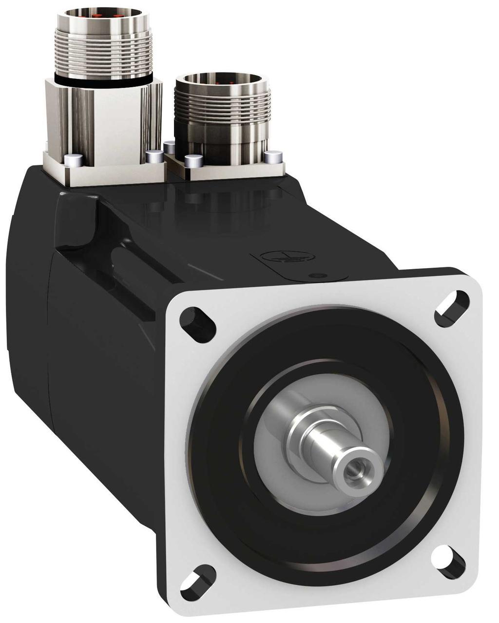
15 BMH 1 Introduction 1 Introduction 1.1 Motor family Characteristics The motors are AC synchronous servo motors with a very high power density. A drive system consists of the AC synchronous servo motor and the appropriate drive. Maximum performance requires the motor and drive to be adapted to each other. The AC synchronous servo motors feature: High power density: the use of the latest magnetic materials and an optimized design result in motors with a shorter length at a comparable torque. High peak torque: the peak torque can be up to four times the continuous stall torque 1.2 Options and accessories The motors are available with various options such as: Various encoder systems Holding brake Various shaft versions Various degrees of protection Various lengths Various sizes Various winding versions Various connection versions Fan cooling The options can be found in the type code section on page 19. For accessories see chapter "6 Accessories and spare parts", page 87. Gearboxes adapted to the motor can be found in the Lexium 32 product catalog. Servo motor 15
16 1 Introduction BMH 1.3 Nameplate BMH070 and BMH100 The nameplate contains the following data: BMH ID-No UN Imax nmax I0 M0 PN nn Vrms 0.00 Arms 0000 rpm 0.00 Arms 0.00 Nm 0.00 kw 0000 rpm C Ubr 00Vdc DOM QD SN US 3~ Th-CI F IP50(65) Mbr 00Nm IEC Made in Germany Thermo- Pbr 00W dd.mm.yyyy Figure 1: Nameplate BMH070 and BMH100 (1) Motor type, see type code (2) Identification number (3) Maximum nominal value of supply voltage (4) Maximum Current (5) Maximum speed of rotation (6) Continuous stall current (7) Continuous stall torque (8) Nominal power (9) Nominal speed of rotation (10) Number of motor phases (11) Thermal class (12) Degree of protection (housing without shaft bushing) (13) Temperature sensor (14) Holding brake data (15) Date of manufacture (16) Serial number (17) Applied standard (18) Country of manufacture, site (19) Barcode 16 Servo motor
17 BMH 1 Introduction BMH140 and BMH BMH ID-No ~ Th-CI F UN 000 Vrms Ubr 00 V Imax 0.00 Arms nmax 0000 rpm Mass 00kg I Arms M Nm FanOption PN 0.00 kw Ufan 00 VDC nn 0000 rpm Pfan 00 W C US IP50(65) Thermo - Pbr 00 W DOM QD SN IEC Made in Germany Mbr 00 Nm dd.mm.yyyy Figure 2: Nameplate BMH140 and BMH190 (1) Motor type, see type code (2) Identification number (3) Maximum nominal value of supply voltage (4) Maximum Current (5) Maximum speed of rotation (6) Continuous stall current (7) Continuous stall torque (8) Nominal power (9) Nominal speed of rotation (10) Fan data (BMH1904 B only) (11) Number of motor phases (12) Thermal class (13) Degree of protection (housing without shaft bushing) (14) Temperature sensor (15) Holding brake data (16) Date of manufacture (17) Serial number (18) Mass of the motor (19) Applied standard (20) Country of manufacture, site (21) Barcode Servo motor 17
18 1 Introduction BMH BMH Made in Germany BMH M0 I Nm 0.00 Arms nn 0000 rpm UN 000 Vrms PN 0.00 kw Th-CI F BL03 Imax nmax C US 0.00 Arms 0000 rpm IP 50 (IP65) Thermo PTC SN DOM QD RS Ubr Pbr Mbr dd.mm.yyyy 0 Vdc 0 W 0 Nm Figure 3: Nameplate BMH205 (1) Motor type, see type code (2) Continuous stall torque (3) Continuous stall current (4) Nominal speed of rotation (5) Maximum nominal value of supply voltage (6) Nominal power (7) Thermal class (8) Barcode (9) Country of manufacture, site (10) Maximum Current (11) Serial number (12) Date of manufacture (13) Hardware version (14) Maximum speed of rotation (15) Degree of protection (housing without shaft bushing) (16) Holding brake data (17) Temperature sensor 18 Servo motor
19 BMH 1 Introduction 1.4 Type code Product family BMH: Synchronous motor - medium moment of inertia BMH P 0 1 A 1 A Size (housing) 070 = 70 mm flange 100 = 100 mm flange 140 = 140 mm flange 190 = 190 mm flange 205 = 205 mm flange Length 1 = 1 stack 2 = 2 stacks 3 = 3 stacks 4 = 4 stacks Winding P = Optimized in terms of torque and speed of rotation T = Optimized in terms of high speed of rotation Shaft and degree of protection 0 = Smooth shaft; degree of protection: shaft IP54 1), housing IP65 1 = Parallel key; degree of protection: shaft IP 54 1), housing IP 65 2 = Smooth shaft; degree of protection: shaft and housing IP65 1) 2) 3 = Parallel key; degree of protection: shaft and housing IP 65 1) 2) Encoder system 1 = Absolute singleturn 128 Sin/Cos periods per revolution (SKS36) 2 = Absolute multiturn 128 Sin/Cos periods per revolution (SKM36) 6 = Absolute singleturn 16 Sin/Cos periods per revolution (SEK37) 7 = Absolute multiturn 16 Sin/Cos periods per revolution (SEL37) Holding brake A = Without holding brake F = With holding brake Connection version 1 = Straight connector 2 = Angular connector 90, can be rotated Mechanical interface - mounting A = International IEC Standard B = International IEC standard and fan cooling 1) In the case of mounting position IM V3 (drive shaft vertical, shaft end up), the motor only has degree of protection IP50. 2) The maximum permissible speed of rotation is limited to 6000 rpm by the shaft sealing ring. Separate accessories allow you to obtain degree of protection IP67. See chapter "6 Accessories and spare parts". Designation customized version If you have questions concerning the type code, contact your Schneider Electric sales office. In the case of a customized version, position 8 of the type code is an "S". The subsequent number defines the customized version. Example: B S1234 Contact your machine vendor if you have questions concerning customized versions. Servo motor 19
20 1 Introduction BMH 20 Servo motor
21 BMH 2 Technical Data 2 Technical Data This chapter contains information on the ambient conditions and on the mechanical and electrical properties of the product family and the accessories. 2.1 General characteristics Motor type Number of pairs of poles 5 AC synchronous servo motor Degree of protection motor housing IP65 As per IEC Degree of protection shaft bushing without shaft sealing ring Degree of protection shaft bushing with shaft sealing ring IP54 ) As per IEC IP65 1) 2) As per IEC Degree of protection with IP67 kit IP67 ) As per IEC Degree of protection with fan IP20 As per IEC Thermal class F (155 C ) As per IEC Vibration grade A As per IEC Test voltage > 2400 Vac As per IEC Maximum permissible winding voltage BMH T 240 Vac BMH P 480 Vac Maximum voltage to ground 280 Vac Perpendicularity normal class As per IEC , DIN Housing color Black RAL 9005 Overvoltage category III As per IEC Protection class 3) I As per IEC 61140, EN ) With shaft sealing ring: the maximum speed of rotation is limited to 6000 rpm; shaft sealing ring with initial lubrication, if the seal runs dry, this increases friction and reduces service life. 2) In the case of mounting position IM V3 (drive shaft vertical, shaft end up), the motor only has degree of protection IP50. The degree of protection only relates to the motor itself, not to mounted components such as, for example, a gearbox. 3) The signals of the holding brake at CN1 and the signals at CN2 meet the PELV requirements. Compatibility with foreign substances Climatic environmental conditions transportation and storage The motor has been tested for compatibility with many known substances and with the latest available knowledge. Nonetheless, you must perform a compatibility test prior to using a foreign substance. The environment during transportation and storage must be dry and free from dust. The storage time is primarily limited by the service life of the lubricants in the bearings. Do not store the product for more than 36 months and periodically operate the motor. If the holding brake is not used for an extended period of time, parts of the holding brake may corrode. Corrosion reduces the holding torque. See "Inspecting/breaking in the holding brake" in chapter "7 Service, maintenance and disposal". Servo motor 21
22 2 Technical Data BMH Temperature C ( F) Relative humidity (non-condensing) Set of class combinations as per IEC % ( ) IE 21 Climatic environmental conditions operation Ambient temperature 1) 2) (no icing, non-condensing) C ( F) Ambient temperature with current C derating of 1% per C (per 1.8 F) ( F) 1) 2) ( ) ( ) Relative humidity (non-condensing) Class as per IEC Installation altitude 3) Installation altitude with current reduction of 1% per 100 m (328 ft) at altitudes of more than 1000 m (3281 ft) 3) % m (ft) m (ft) 3K3, 3Z12, 3Z2, 3B2, 3C1, 3M6 <1000 (<3281) ( ) 1) Limit values with flanged motor (steel plate, height and width = 2.5 * motor flange, 10 mm (0.39 in) thickness, centered hole). 2) BMH1904 B: The fan, which is delivered with the motor, is required for operation. For more information, refer to chapter "3.6 Mounting and connecting the fan (BMH1904 B only)". 3) The installation altitude is defined in terms of altitude above mean sea level. Vibration and shock BMH Vibration, sinusoidal Shock, semi-sinusoidal Type test with 10 runs as per IEC mm ( Hz) 20 m/s 2 ( Hz) Type test with 3 shocks in each direction as per IEC m/s 2 (11 ms) Vibration and shock BMH205 Vibration, sinusoidal Shock, semi-sinusoidal Type test with 10 runs as per IEC mm ( Hz) 50 m/s 2 ( Hz) Type test with 3 shocks in each direction as per IEC m/s 2 (6 ms) 22 Servo motor
23 BMH 2 Technical Data Service life Shaft sealing ring / degree of protection Compressed air connection Nominal bearing service life L10h 1) h ) Operating hours at a probability of failure of 10% The service life of the motors when operated correctly is limited primarily by the service life of the rolling bearing. The following operating conditions significantly reduce the service life: Installation altitude >1000 m (3281 ft) above mean sea level Rotary movements exclusively within a fixed angle of <100 Operation under vibration load >20 m/s 2 Allowing sealing rings to run dry Contact of the seals with aggressive substances The motors can be equipped with an optional shaft sealing ring. With a shaft sealing ring, they have degree of protection IP65. The shaft sealing ring limits the maximum speed of rotation to 6000 rpm. Note the following: The shaft sealing ring is factory-pre-lubricated. If the seals run dry, this increases friction and greatly reduces the service life of the sealing rings. The compressed air generates a permanent overpressure inside the motor. This overpressure inside the motor is used to obtain degree of protection IP67. Compressed air must also be available when the system is switched off, for example to maintain the required degree of protection during cleaning work. When the compressed air is switched off, the degree of protection is decreased to IP65. The degree of protection only relates to the motor itself, not to mounted components such as, for example, a gearbox. Special compressed air must be used: Nominal pressure Maximum air pressure bar (psi) bar (psi) ( ) 0.4 (5.8) Permissible humidity % Other properties of the compressed air Free from dust, free from oil Servo motor 23
24 2 Technical Data BMH Tightening torque and property class of screws used Tightening torque of housing screws M3 Nm (lb in) 1 (8.85) Tightening torque of housing screws M4 Nm (lb in) 1.5 (13.28) Tightening torque of housing screws M5 Nm (lb in) 5 (44.3) Tightening torque protective ground conductor M4 (BMH ) Tightening torque protective ground conductor M6 (BMH190) Tightening torque protective ground conductor M6 (BMH205) Nm (lb in) 2.9 (25.7) Nm (lb in) 6 (53.1) Nm (lb in) 9.9 (87.3) Property class of the screws 8.8 Approved drives You may use drives that are approved for the BMH motor family (for example, LXM32). When selecting, consider the type and amount of the mains voltage. Inquire for additional drives that can be used to operate BMH motors. Note that the BMH motor does not have a conventional temperature sensor. 24 Servo motor
25 BMH 2 Technical Data 2.2 Motor-specific data BMH070 BMH Winding P T P T P T Technical data - general Continuous stall torque M0 Peak torque Mmax 1) 2) Nm With supply voltage Un = 115 Vac 1) (lb in) Nm (lb in) 1.40 (12.39) 4.20 (37.17) 1.40 (12.39) 4.20 (37.17) 2.48 (21.95) 7.44 (65.85) 2.48 (21.95) 7.44 (65.85) 3.40 (30.09) (90.28) Nominal speed of rotation nn rpm Nominal torque MN Nm (lb in) 1.38 (12.21) 1.35 (11.95) 2.37 (20.98) 2.27 (20.09) 3.18 (28.15) Nominal current IN Arms Nominal power PN kw With supply voltage Un = 230 Vac 1) Nominal speed of rotation nn rpm Nominal torque MN Nm (lb in) 1.34 (11.86) 1.31 (11.59) 2.23 (19.74) 2.06 (18.23) 2.96 (26.20) Nominal current IN Arms Nominal power PN kw With supply voltage Un = 400 Vac 1) Nominal speed of rotation nn rpm Nominal torque MN Nm (lb in) 1.30 (11.51) (17.79) (22.39) Nominal current IN Arms Nominal power PN kw With supply voltage Un = 480 Vac 1) Nominal speed of rotation nn rpm Nominal torque MN Nm (lb in) 1.27 (11.24) (16.73) (20.00) Nominal current IN Arms Nominal power PN kw (30.09) (90.28) 3.05 (26.99) 2.70 (23.90) 1) Conditions for performance data: Mounted to steel plate (2.5 * flange dimension) 2 area, 10 mm (0.39 in) thickness, centered hole. 2) M0 = Continuous stall torque at 20 rpm and 100% duty cycle; at speeds of rotation of < 20 rpm the continuous stall torque is reduced to 87%. - - Servo motor 25
26 2 Technical Data BMH BMH Winding P T P T P T Technical data - electrical Maximum current Imax Arms Continuous stall current I0 Arms Voltage constant keu-v 1) Vrms Torque constant kt 2) Nm/A Winding resistance R20u-v Ω Winding inductance Lqu-v mh Winding inductance Ldu-v mh Technical data - mechanical Maximum speed of rotation nmax rpm Rotor inertia without holding brake JM kgcm Rotor inertia with holding brake JM kgcm Mass without holding brake m kg Mass with holding brake m kg ) RMS value at 1000 rpm and 20 C (68 F). 2) At n = 20 rpm and 100% duty cycle. 26 Servo motor
27 BMH 2 Technical Data BMH100 BMH Winding P T P T P T Technical data - general Continuous stall torque M0 Peak torque Mmax 1) 2) Nm With supply voltage Un = 115 Vac 1) (lb in) Nm (lb in) 3.40 (30.09) (90.28) 3.40 (30.09) (90.28) 6.0 (53.10) (159.31) 6.1 (53.99) (161.97) 9.0 (79.66) (238.97) Nominal speed of rotation nn rpm Nominal torque MN Nm (lb in) 3.30 (29.21) 3.20 (28.32) 5.67 (50.18) 5.75 (50.89) 8.45 (74.79) Nominal current IN Arms Nominal power PN kw With supply voltage Un = 230 Vac 1) Nominal speed of rotation nn rpm Nominal torque MN Nm (lb in) 3.20 (28.32) 2.90 (25.67) 5.33 (47.17) 4.80 (42.48) 7.63 (67.53) Nominal current IN Arms Nominal power PN kw With supply voltage Un = 400 Vac 1) Nominal speed of rotation nn rpm Nominal torque MN Nm (lb in) 3.00 (26.55) (41.33) (53.10) Nominal current IN Arms Nominal power PN kw With supply voltage Un = 480 Vac 1) Nominal speed of rotation nn rpm Nominal torque MN Nm (lb in) 2.90 (25.67) (37.17) (42.31) Nominal current IN Arms Nominal power PN kw (66.38) (225.69) 7.88 (69.74) 7.25 (64.17) 1) Conditions for performance data: Mounted to steel plate, 300 mm (11.8 in) * 300 mm (11.8 in) area, 20 mm (0.79 in) thickness, centered hole. 2) M0 = Continuous stall torque at 20 rpm and 100% duty cycle; at speeds of rotation of < 20 rpm the continuous stall torque is reduced to 87%. - - Servo motor 27
28 2 Technical Data BMH BMH Winding P T P T P T Technical data - electrical Maximum current Imax Arms Continuous stall current I0 Arms Voltage constant keu-v 1) Vrms Torque constant kt 2) Nm/A Winding resistance R20u-v Ω Winding inductance Lqu-v mh Winding inductance Ldu-v mh Technical data - mechanical Maximum speed of rotation nmax rpm Rotor inertia without holding brake JM kgcm Rotor inertia with holding brake JM kgcm Mass without holding brake m kg Mass with holding brake m kg ) RMS value at 1000 rpm and 20 C (68 F). 2) At n = 20 rpm and 100% duty cycle. 28 Servo motor
29 BMH 2 Technical Data BMH140 BMH Winding P P P Technical data - general Continuous stall torque M0 Peak torque Mmax 1) 2) Nm With supply voltage Un = 115 Vac 1) (lb in) Nm (lb in) 10.0 (88.51) (265.5) 16.8 (148.7) (446.1) Nominal speed of rotation nn rpm Nominal torque MN Nm (lb in) 9.08 (80.36) (131.9) 22.5 (199.1) (637.3) (190.3) Nominal current IN Arms Nominal power PN kw With supply voltage Un = 230 Vac 1) Nominal speed of rotation nn rpm Nominal torque MN Nm (lb in) 8.30 (73.46) (115.9) (160.4) Nominal current IN Arms Nominal power PN kw With supply voltage Un = 400 Vac or Un = 480 Vac 1) Nominal speed of rotation nn rpm Nominal torque MN Nm (lb in) 7.14 (63.19) (100.0) (123.2) Nominal current IN Arms Nominal power PN kw ) Conditions for performance data: Mounted to steel plate, 400 mm (15.7 in) * 400 mm (15.7 in) area, 10 mm (0.39 in) thickness, centered hole. 2) M0 = Continuous stall torque at 20 rpm and 100% duty cycle; at speeds of rotation of < 20 rpm the continuous stall torque is reduced to 87%. Servo motor 29
30 2 Technical Data BMH BMH Winding P P P Technical data - electrical Maximum current Imax Arms Continuous stall current I0 Arms Voltage constant keu-v 1) Vrms Torque constant kt 2) Nm/A Winding resistance R20u-v Ω Winding inductance Lqu-v mh Winding inductance Ldu-v mh Technical data - mechanical Maximum speed of rotation nmax rpm Rotor inertia without holding brake JM kgcm Rotor inertia with holding brake JM kgcm Mass without holding brake m kg Mass with holding brake m kg ) RMS value at 1000 rpm and 20 C (68 F). 2) At n = 20 rpm and 100% duty cycle. 30 Servo motor
31 BMH 2 Technical Data BMH190 BMH A 1904 B Winding P P P P P Technical data - general Continuous stall torque M0 Peak torque Mmax 1) 2) Nm (lb in) Nm (lb in) With supply voltage Un = 400 Vac or Un = 480 Vac 1) 30.0 (265.5) 90 (796.6) 48.0 (424.8) 144 (1275) 65.0 (575.3) 195 (1726) 100 (885.1) 230 (2036) Nominal speed of rotation nn rpm Nominal torque MN Nm (lb in) (146.0) (256.7) (327.5) (414.2) 100 (885.1) 230 (2036) (676.2) Nominal current IN Arms Nominal power PN kw ) Conditions for performance data: Mounted to steel plate, 550 mm (21.7 in) * 550 mm (21.7 in) area, 30 mm (1.18 in) thickness, centered hole. 2) M0 = Continuous stall torque at 20 rpm and 100% duty cycle; at speeds of rotation of < 20 rpm the continuous stall torque is reduced to 87%. BMH A 1904 B Winding P P P P P Technical data - electrical Maximum current Imax Arms Continuous stall current I0 Arms Voltage constant keu-v 1) Vrms Torque constant kt 2) Nm/A Winding resistance R20u-v Ω Winding inductance Lqu-v mh Winding inductance Ldu-v mh Technical data - mechanical Maximum speed of rotation nmax rpm Rotor inertia without holding brake JM kgcm Rotor inertia with holding brake JM kgcm Mass without holding brake m kg Mass with holding brake m kg ) RMS value at 1000 rpm and 20 C (68 F). 2) At n = 20 rpm and 100% duty cycle. Servo motor 31
32 2 Technical Data BMH BMH205 BMH Winding P P P Technical data - general Continuous stall torque M0 Peak torque Mmax 1) 2) Nm With supply voltage Un = 115 Vac 1) (lb in) Nm (lb in) 34.4 (304.5) 110 (973.6) 62.5 (553.2) 220 (1947) Nominal speed of rotation nn rpm Nominal torque MN Nm (lb in) 31.4 (277.9) 57.9 (512.5) Nominal current IN Arms Nominal power PN kw With supply voltage Un = 230 Vac 1) 88 (778.9) 330 (2921) 80.2 (709.8) Nominal speed of rotation nn rpm Nominal torque MN Nm (lb in) 28.2 (249.6) 51.7 (457.6) Nominal current IN Arms Nominal power PN kw With supply voltage Un = 400 Vac 1) 70.4 (623.1) Nominal speed of rotation nn rpm Nominal torque MN Nm (lb in) 21.0 (185.9) 34.0 (300.9) Nominal current IN Arms Nominal power PN kw With supply voltage Un = 480 Vac 1) 45.0 (398.3) Nominal speed of rotation nn rpm Nominal torque MN Nm (lb in) 17.9 (158.4) 24.9 (220.4) Nominal current IN Arms Nominal power PN kw (398.3) 1) Conditions for performance data: Mounted to steel plate (2.5 * flange dimension) 2 area, 10 mm (0.39 in) thickness, centered hole. 2) M0 = Continuous stall torque at 20 rpm and 100% duty cycle; at speeds of rotation of < 20 rpm the continuous stall torque is reduced to 87%. 32 Servo motor
33 BMH 2 Technical Data BMH Winding P P P Technical data - electrical Maximum current Imax Arms Continuous stall current I0 Arms Voltage constant keu-v 1) Vrms Torque constant kt 2) Nm/A Winding resistance R20u-v Ω Winding inductance Lqu-v mh Winding inductance Ldu-v mh Technical data - mechanical Maximum speed of rotation nmax rpm Rotor inertia without holding brake JM kgcm Rotor inertia with holding brake JM kgcm Mass without holding brake m kg Mass with holding brake m kg ) RMS value at 1000 rpm and 20 C (68 F). 2) At n = 20 rpm and 100% duty cycle. Servo motor 33
34 2 Technical Data BMH 2.3 Dimensions Dimensions BMH070 mm in M4x Ø82 Ø3.32 ØC k6 Ø60 j6 Ø2.362 j Ø75 Ø2.95 ±1 L B DIN 6885 A B A ØC k6 E A F G H A-A D h DIN 332-D ØT O N P Q ØS Figure 4: Dimensions BMH070 BMH L Length without holding brake mm (in) 122 (4.80) 154 (6.06) 186 (7.32) L Length with holding brake mm (in) 161(6.34) 193 (7.60) 225 (8.86) B Shaft length mm (in) 23 (0.91) 23 (0.91) 30 (1.18) C Shaft diameter mm (in) 11 (0.433) 11 (0.433) 14 (0.551) D Width of parallel key mm (in) 4 (0.157) 4 (0.157) 5 (0.197) E Shaft width with parallel key mm (in) 12.5 (0.49) 12.5 (0.49) 16 (0.63) F Length of parallel key mm (in) 18 (0.71) 18 (0.71) 20 (0.79) G Distance parallel key to shaft end mm (in) 2.5 (0.10) 2.5 (0.10) 5 (0.20) Parallel key DIN 6885-A4x4x18 DIN 6885-A4x4x18 DIN 6885-A4x4x20 H Female thread of shaft M4 M4 M5 N mm (in) 2.1 (0.08) 2.1 (0.08) 2.4 (0.09) O mm (in) 3.2 (0.13) 3.2 (0.13) 4 (0.16) P mm (in) 10 (0.39) 10 (0.39) 12.5 (0.49) Q mm (in) 14 (0.55) 14 (0.55) 17 (0.67) S mm (in) 4.3 (0.17) 4.3 (0.17) 5.3 (0.21) T mm (in) 3.3 (0.13) 3.3 (0.13) 4.2 (0.17) 34 Servo motor
35 BMH 2 Technical Data Dimensions BMH100 mm in Ø9 Ø0.35 Ø115 Ø4.53 M4x10 ØC k6 Ø95 j6 Ø3.740 j L ± B DIN 6885 A B A ØC k6 E A F G H A-A D h DIN 332-D ØT O N P Q ØS Figure 5: Dimensions BMH100 BMH L Length without holding brake mm (in) (5.06) (6.32) (7.58) L Length with holding brake mm (in) (6.7) (7.96) (9.22) B Shaft length mm (in) 40 (1.57) 40 (1.57) 40 (1.57) C Shaft diameter mm (in) 19 (0.748) 19 (0.748) 19 (0.748) D Width of parallel key mm (in) 6 (0.236) 6 (0.236) 6 (0.236) E Shaft width with parallel key mm (in) 21.5 (0.85) 21.5 (0.85) 21.5 (0.85) F Length of parallel key mm (in) 30 (1.18) 30 (1.18) 30 (1.18) G Distance parallel key to shaft end mm (in) 5 (0.2) 5 (0.2) 5 (0.2) Parallel key DIN 6885-A6x6x30 DIN 6885-A6x6x30 DIN 6885-A6x6x30 H Female thread of shaft M6 M6 M6 N mm (in) 2.8 (0.11) 2.8 (0.11) 2.8 (0.11) O mm (in) 5 (0.2) 5 (0.2) 5 (0.2) P mm (in) 16 (0.63) 16 (0.63) 16 (0.63) Q mm (in) 21 (0.83) 21 (0.83) 21 (0.83) S mm (in) 6.4 (0.25) 6.4 (0.25) 6.4 (0.25) T mm (in) 5 (0.2) 5 (0.2) 5 (0.2) Servo motor 35
36 2 Technical Data BMH Dimensions BMH140 mm in Ø11 Ø0.43 Ø165 Ø L ±1 M4x DIN 6885 A B B A ØC k6 ØC k6 Ø130 j6 Ø5.118 j6 E DIN 332-D ØT A F O N G H A-A D h9 P Q ØS Figure 6: Dimensions BMH140 BMH L Length without holding brake mm (in) 152 (5.98) 192 (7.56) 232 (9.13) L Length with holding brake mm (in) 187 (7.36) 227 (8.94) 267 (10.51) B Shaft length mm (in) 50 (1.97) 50 (1.97) 50 (1.97) C Shaft diameter mm (in) 24 (0.945) 24 (0.945) 24 (0.945) D Width of parallel key mm (in) 8 (0.315) 8 (0.315) 8 (0.315) E Shaft width with parallel key mm (in) 27 (1.06) 27 (1.06) 27 (1.06) F Length of parallel key mm (in) 40 (1.57) 40 (1.57) 40 (1.57) G Distance parallel key to shaft end mm (in) 5 (0.2) 5 (0.2) 5 (0.2) Parallel key DIN 6885-A8x7x40 DIN 6885-A8x7x40 DIN 6885-A8x7x40 H Female thread of shaft M8 M8 M8 N mm (in) 3.3 (0.13) 3.3 (0.13) 3.3 (0.13) O mm (in) 6 (0.24) 6 (0.24) 6 (0.24) P mm (in) 19( 0.75) 19( 0.75) 19( 0.75) Q mm (in) 25 (0.98) 25 (0.98) 25 (0.98) S mm (in) 8.4 (0.33) 8.4 (0.33) 8.4 (0.33) T mm (in) 6.8 (0.27) 6.8 (0.27) 6.8 (0.27) 36 Servo motor
37 BMH 2 Technical Data Dimensions BMH190 A mm in X M Ø14 Ø0.55 Ø215 Ø ØC k6 Ø180 j6 Ø7.087 j L B DIN 6885 A B A ØC k6 E DIN 332-D ØT A F O N G H A-A D h9 P Q ØS Figure 7: Dimensions BMH190 A BMH A L Length without holding brake mm (in) 190 (7.48) 250 (9.84) 310 (12.2) 383 (15.08) L Length with holding brake mm (in) 248 (9.76) 308 (12.13) 368 (14.49) 456 (17.95) X Length without holding brake mm (in) 65 (2.56) 65 (2.56) 65 (2.56) 65 (2.56) X Length with holding brake mm (in) 123 (4.84) 123 (4.84) 123 (4.84) 123 (4.84) B Shaft length mm (in) 80 (3.15) 80 (3.15) 80 (3.15) 80 (3.15) C Shaft diameter mm (in) 38 (1.496) 38 (1.496) 38 (1.496) 38 (1.496) D Width of parallel key mm (in) 10 (0.394) 10 (0.394) 10 (0.394) 10 (0.394) E Shaft width with parallel key mm (in) 41 (1.61) 41 (1.61) 41 (1.61) 41 (1.61) F Length of parallel key mm (in) 70 (2.76) 70 (2.76) 70 (2.76) 70 (2.76) G Distance parallel key to shaft end mm (in) 5 (0.2) 5 (0.2) 5 (0.2) 5 (0.2) Parallel key DIN A10x8x70 DIN A10x8x70 DIN A10x8x70 H Female thread of shaft M12 M12 M12 M12 DIN A10x8x70 N mm (in) 4.4 (0.17) 4.4 (0.17) 4.4 (0.17) 4.4 (0.17) O mm (in) 9.5 (0.37) 9.5 (0.37) 9.5 (0.37) 9.5 (0.37) P mm (in) 28 (1.1) 28 (1.1) 28 (1.1) 28 (1.1) Q mm (in) 37 (1.46) 37 (1.46) 37 (1.46) 37 (1.46) S mm (in) 13 (0.51) 13 (0.51) 13 (0.51) 13 (0.51) T mm (in) 10.2 (0.4) 10.2 (0.4) 10.2 (0.4) 10.2 (0.4) Servo motor 37
38 2 Technical Data BMH Dimensions BMH1904 B mm in Ø14 Ø0.55 Ø215 Ø X M ØC k6 Ø180 j6 Ø7.087 j L DIN 6885 A B B A ØC k6 E DIN 332-D ØT A F O N G H A-A D h9 P Q ØS Figure 8: Dimensions BMH1904 B BMH B L Length without holding brake mm (in) (17.70) L Length with holding brake mm (in) 523 (20.59) X Length without holding brake mm (in) 135 (5.31) X Length with holding brake mm (in) (7.62) B Shaft length mm (in) 80 (3.15) C Shaft diameter mm (in) 38 (1.496) D Width of parallel key mm (in) 10 (0.398) E Shaft width with parallel key mm (in) 41 (1.61) F Length of parallel key mm (in) 70 (2.76) G Distance parallel key to shaft end mm (in) 5 (0.2) Parallel key DIN A10x8x70 H Female thread of shaft M12 N mm (in) 4.4 (0.17) O mm (in) 9.5 (0.37) P mm (in) 28 (1.1) Q mm (in) 37 (1.46) S mm (in) 13 (0.51) T mm (in) 10.2 (0.4) 38 Servo motor
39 54 BMH 2 Technical Data Dimensions BMH205 mm in M Ø14 Ø0.55 Ø215 Ø8.46 Ø Ck6 Ø180 j6 Ø7.087 j ±1 L B DIN 6885 A B A ØC k6 E DIN 332-D ØT A F O N P Q G ØS H A-A D h9 Figure 9: Dimensions BMH205 BMH L Length without holding brake mm (in) 321 (12.64) 405 (15.94) 489 (19.25) L Length with holding brake mm (in) (14.57) (17.89) (21.20) B Shaft length mm (in) 80 (3.15) 80 (3.15) 80 (3.15) C Shaft diameter mm (in) 38 (1.496) 38 (1.496) 38 (1.496) D Width of parallel key mm (in) 10 (0.398) 10 (0.398) 10 (0.398) E Shaft width with parallel key mm (in) 41 (1.61) 41 (1.61) 41 (1.61) F Length of parallel key mm (in) 70 (2.76) 70 (2.76) 70 (2.76) G Distance parallel key to shaft end mm (in) 5 (0.2) 5 (0.2) 5 (0.2) Parallel key DIN A10x8x70 DIN A10x8x70 H Female thread of shaft M12 M12 M12 DIN A10x8x70 N mm (in) 4.4 (0.17) 4.4 (0.17) 4.4 (0.17) O mm (in) 9.5 (0.37) 9.5 (0.37) 9.5 (0.37) P mm (in) 28 (1.1) 28 (1.1) 28 (1.1) Q mm (in) 37 (1.46) 37 (1.46) 37 (1.46) S mm (in) 13 (0.51) 13 (0.51) 13 (0.51) T mm (in) 10.2 (0.4) 10.2 (0.4) 10.2 (0.4) Servo motor 39
40 2 Technical Data BMH 2.4 Shaft-specific data Force for pressing on If the maximum permissible forces at the motor shaft are exceeded, this will result in premature wear of the bearing or shaft breakage. WARNING UNINTENDED EQUIPMENT OPERATION DUE TO MECHANICAL DAM- AGE TO THE MOTOR Do not exceed the maximum permissible axial and radial forces at the motor shaft. Protect the motor shaft from impact. Do not exceed the maximum permissible axial force when pressing components onto the motor shaft. Failure to follow these instructions can result in death, serious injury, or equipment damage. Maximum force during pressing on The force applied during pressing on must not exceed the maximum permissible axial force, see chapter "2.4.2 Shaft load". Applying assembly paste to the shaft and the component to be mounted reduces friction and mechanical impact on the surfaces. If the shaft has a thread, use it to press on the component to be mounted. This way there is no axial force acting on the rolling bearing. It is also possible to shrink-fit, clamp or glue the component to be mounted. The following table shows the maximum permissible axial force F A at standstill. BMH Maximum axial force FA at standstill N (lb) 80 (18) 160 (36) 300 (65) 500 (112) 740 (165) 40 Servo motor
41 BMH 2 Technical Data Shaft load The following conditions apply: The permissible force applied during pressing on must not be exceed. Radial and axial limit loads must not be applied simultaneously Nominal bearing service life in operating hours at a probability of failure of 10% (L 10h = hours) Mean speed of rotation n = 4000 rpm Ambient temperature = 40 C (104 F) Peak torque = Duty types S3 - S8, 10% duty cycle Nominal torque = Duty type S1, 100% duty cycle F R F A X Figure 10: Shaft load The point of application of the forces depends on the motor size: Motor version Values for "X" BMH0701 and BMH0702 mm (in) 11.5 (0.45) BMH0703 mm (in) 15 (0.59) BMH100 mm (in) 20 (0.76) BMH140 mm (in) 25 (0.98) BMH190 mm (in) 40 (1.57) BMH205 mm (in) 40 (1.57) Servo motor 41
42 2 Technical Data BMH The following table shows the maximum radial shaft load F R. BMH rpm N (lb) 2000 rpm N (lb) 3000 rpm N (lb) 4000 rpm N (lb) 5000 rpm N (lb) 6000 rpm N (lb) 660 (148) 520 (117) 460 (103) 410 (92) 380 (85) 360 (81) 710 (160) 560 (126) 490 (110) 450 (101) 410 (92) 390 (88) 730 (164) 580 (130) 510 (115) 460 (103) 430 (97) 400 (90) 900 (202) 720 (162) 630 (142) 570 (128) 530 (119) 990 (223) 790 (178) 690 (155) 620 (139) 580 (130) 1050 (236) 830 (187) 730 (164) 660 (148) 610 (137) 1930 (434) 1530 (344) 1340 (301) 2240 (544) 1780 (400) 1550 (348) (544) 1920 (432) 1670 (375) BMH rpm N (lb) 2000 rpm N (lb) 3000 rpm N (lb) 4000 rpm N (lb) 2900 (652) 2750 (618) 2650 (596) 2600 (585) 3200 (719) 3100 (697) 3000 (674) 2950 (663) 3300 (742) 3250 (731) 3150 (708) 3100 (697) 3800 (854) 3700 (832) 3600 (809) 3500 (787) 3730 (839) 2960 (665) 2580 (580) 4200 (944) 3330 (749) 2910 (654) (1012) 3570 (803) 3120 (701) The following table shows the maximum axial shaft load F A. BMH rpm N (lb) 2000 rpm N (lb) 3000 rpm N (lb) 4000 rpm N (lb) 5000 rpm N (lb) 6000 rpm N (lb) 132 (30) 104 (23) 92 (21) 82 (18) 76 (17) 72 (16) 142 (32) 112 (25) 98 (22) 90 (20) 82 (18) 78 (18) 146 (33) 116 (26) 102 (23) 92 (21) 86 (19) 80 (18) 180 (40) 144 (32) 126 (28) 114 (26) 106 (24) 198 (45) 158 (36) 138 (31) 124 (28) 116 (26) 210 (47) 166 (37) 146 (33) 132 (30) 122 (27) 386 (87) 306 (69) 268 (60) 448 (109) 356 (86) 310 (75) (109) 384 (86) 334 (75) BMH rpm N (lb) 2000 rpm N (lb) 3000 rpm N (lb) 4000 rpm N (lb) 580 (130) 550 (124) 530 (119) 520 (117) 640 (144) 620 (139) 600 (135) 590 (133) 660 (148) 650 (146) 630 (142) 620 (139) 760 (171) 740 (166) 720 (162) 700 (157) Servo motor
BMH Servo motor Motor manual V1.03,
 Servo motor Motor manual V1.03, 11.2011 www.schneider-electric.com Important information BMH Important information This manual is part of the product. Carefully read this manual and observe all instructions.
BMP. Synchronous motor Motor manual V1.3, , V1.3,
 BMP Synchronous motor Motor manual V1.3, 01.2017 www.schneider-electric.com The information provided in this documentation contains general descriptions and/or technical characteristics of the performance
BMP Synchronous motor Motor manual V1.00,
 BMP Synchronous motor Motor manual V1.00, 12.2012 www.schneider-electric.com Important information BMP Important information This manual is part of the product. Carefully read this manual and observe all
Technical Documentation
 Technical Documentation Product manual Holding brake controller Document: 0198441113316 Edition: V1.00, 03.2006 Important information The drive systems described here are products for general use that
Altivar Regenerative Unit
 Altivar Regenerative Unit User Manual 11/2016 NVE88423-10/2016 www.schneider-electric.com The information provided in this documentation contains general descriptions and/or technical characteristics of
1 Article designation
 Order code LTi synchronous motors LSx Example LSH07410560 1 Article designation LS LTi synchronous motor series T or H 074 1 0 560 / T H Edge measurement of motor in mm (not the flange measurement) 050
Altivar Installation Manual. English 07/2013 ST /2013.
 Altivar 1200 Installation Manual English 07/2013 ST03196 07/2013 www.schneider-electric.com The information provided in this documentation contains general descriptions and/or technical characteristics
1 Article designation
 Order code LTi synchronous motors LSx Example LSH07410560 1 Article designation LS LTi synchronous motor series T or H 074 1 0 560 / T H Edge measurement of motor in mm (not the flange measurement) 050
Lexium integrated drives
 Description ILp for CANopen, PROFIBUS DP, RS ILE with brushless DC motor Description ILE comprise control electronics with a fieldbus interface for CANopen DS, PROFIBUS DP or RS and a brushless DC motor.
Lexium integrated drives
 Description ILp for DeviceNet, EtherCAT, Modbus TCP, ILE with brushless DC motor Description ILE comprise control electronics with a fieldbus interface for DeviceNet, EtherCAT, Modbus TCP or and a brushless
ILA2D572TC1F0 integrated drive ILA with servo motor V - DeviceNet - indus connector
 Characteristics integrated drive ILA with servo motor - 24..48 V - DeviceNet - indus connector Main Range of product Product or component type Device short name Motor type Number of motor poles 6 Phase
ILE2K661PC1A1 brushless dc motor V- EtherNet/IP interface - L = 174 mm- 18:1
 Characteristics brushless dc motor 24..48V- EtherNet/IP interface - L = 174 mm- 18:1 Main Range of product Product or component type Device short name Motor type Number of motor poles 6 Network number
ILE1F661PC1A0 brushless dc motor V - CANopen DS301 interface - L = 122 mm - w/o gearbox
 Characteristics brushless dc motor 24..36 V - CANopen DS301 interface - L = 122 mm - w/o gearbox Main Range of product Product or component type Device short name Motor type Number of motor poles 6 Network
DYNASYN DD servo motors. Dynamic. Compact. Energy-efficient.
 DYNASYN DD servo motors. Dynamic. Compact. Energy-efficient. B E N E F I T S Maximum dynamic response Increased energy efficiency High cost effectiveness Long service life Single-cable solution 2 DYNASYN
ILA1F572PB1F0 integrated drive ILA with servo motor V - CANopen - PCB connector
 Characteristics integrated drive ILA with servo motor - 24..36 V - CANopen - PCB connector Product availability : Non-Stock - Not normally stocked in distribution facility Price* : 1860.00 USD Main Range
BSH1001P31A2A AC servo motor BSH N.m rpm - keyed shaft - without brake - IP65
 Product data sheet Characteristics BSH1001P31A2A AC servo motor BSH - 2.7 N.m - 3000 rpm - keyed shaft - without brake - IP65 The information provided in this documentation contains general descriptions
ATS22D88Q soft starter-ats22-control 220V-power 230V (22kW)/ V(45kW)
/ V(45kW)") Product datasheet Characteristics ATS22D88Q soft starter-ats22-control 220V-power 230V (22kW)/400...440V(45kW) Complementary Assembly style Function available Supply voltage limits Main Range of product
Product datasheet Characteristics ATS22D88Q soft starter-ats22-control 220V-power 230V (22kW)/400...440V(45kW) Complementary Assembly style Function available Supply voltage limits Main Range of product
ILE2T661PB1A3 brushless dc motor V - Modbus TCP interface - L = 174 mm - 54:1
 Characteristics brushless dc motor 24..48 V - Modbus TCP interface - L = 174 mm - 54:1 Product availability : Non-Stock - Not normally stocked in distribution facility Price* : 1540.00 USD Main Range of
BMH0701P07F2A servo motor BMH Nm rpm - untapped shaft - with brake - IP54
 Characteristics servo motor BMH - 1.2 Nm - 8000 rpm - untapped shaft - with brake - IP54 Main Product or component type Device short name Maximum mechanical speed Continuous stall torque Peak stall torque
Cat. No. I526-E1-1 USER S MANUAL 3G3IV-PLKEB2 /4. Braking Resistor Units 3G3IV-PCDBR2 B/4 B. Braking Units
 Cat. No. I526-E1-1 USER S MANUAL 3G3IV-PLKEB2 /4 Braking Resistor Units 3G3IV-PCDBR2 B/4 B Braking Units Thank you for choosing an OMRON Braking Resistor Unit and Braking Unit. Proper use and handling
SMH High Torque Density
 SMH High Torque Density AC Synchronous Servo Motor Catalogue Version:C Date: January, 207 Kinavo Servo Motor(Changzhou)Ltd. Tel.: +8-0-88037 Fax: +8-0-88072 Website: http://www.kinavo.com Add.: Building
TGN, TGH AND TGT SERVOMOTORS
 TGN, TGH AND TGT SERVOMOTORS Instruction manual. Information furnished by is believed to be accurate and reliable. However, no responsibility is assumed by TG Drives for its use. TG Drives reserves the
BSH0702P12A2A AC servo motor BSH N.m rpm - keyed shaft - without brake - IP50
 Product data sheet Characteristics BSH0702P12A2A AC servo motor BSH - 2.2 N.m - 3000 rpm - keyed shaft - without brake - IP50 The information provided in this documentation contains general descriptions
ILE1F661PB1A0 brushless dc motor V - CANopen DS301 interface - L = 122 mm - w/o gearbox
 Characteristics brushless dc motor 24..36 V - CANopen DS301 interface - L = 122 mm - w/o gearbox Product availability : Stock - Normally stocked in distribution facility Price* : 840.00 USD Main Range
BSH0553T11A2A AC servo motor BSH N.m rpm - keyed shaft - without brake - IP50
 Product data sheet Characteristics BSH0553T11A2A AC servo motor BSH - 1.3 N.m - 3000 rpm - keyed shaft - without brake - IP50 The information provided in this documentation contains general descriptions
ILE1B661PC1A1 brushless dc motor V - Profibus DP interface - L = 174 mm - 18:1
 Characteristics brushless dc motor 24..36 V - Profibus DP interface - L = 174 mm - 18:1 Product availability : Non-Stock - Not normally stocked in distribution facility Price* : 1640.00 USD Main Range
BMH1001P17F2A servo motor BMH Nm rpm - keyed shaft - with brake - IP54
 Characteristics servo motor BMH - 3.3 Nm - 6000 rpm - keyed shaft - with brake - IP54 Main Product or component type Device short name Maximum mechanical speed Continuous stall torque Peak stall torque
PAS4xS. Ball screw axis Product manual V2.05, MNA1MLSDM00EN, V2.05,
 Ball screw axis Product manual V2.05, 03.2015 www.schneider-electric.com The information provided in this documentation contains general descriptions and/or technical characteristics of the performance
BSH0553P11A1A AC servo motor BSH N.m rpm - keyed shaft - without brake - IP50
 Product data sheet Characteristics BSH0553P11A1A AC servo motor BSH - 1.3 N.m - 3000 rpm - keyed shaft - without brake - IP50 The information provided in this documentation contains general descriptions
Altivar Process Variable Speed Drives ATV6000
 Altivar Process QGH83258 01/2019 Altivar Process Variable Speed Drives ATV6000 Installation Manual 01/2019 QGH83258-01 www.schneider-electric.com The information provided in this documentation contains
8JS three-phase synchronous motors Dynamic precision drives
 Dynamic precision drives Modern machine concepts demand compact and powerful motors. The compact AC servo motor series from B&R provides ways for the machine manufacturer to further optimize service and
Accessories for Wind Power Inverter WINDY BOY PROTECTION BOX 400 / 500 / 600
 Accessories for Wind Power Inverter WINDY BOY PROTECTION BOX 400 / 500 / 600 Installation Guide WBP-Box-IEN103320 IMEN-WBP-BOX Version 2.0 EN SMA Solar Technology AG Table of Contents Table of Contents
Product Information ECN 425 EQN 437. Absolute Rotary Encoders with Hollow Shaft and Expanding Ring Coupling for Safety-Related Applications
 Product Information ECN 425 EQN 437 Absolute Rotary Encoders with Hollow Shaft and Expanding Ring Coupling for Safety-Related Applications 4/2014 ECN 425, EQN 437 Rotary encoders for absolute position
DYNASYN Hightorque-Servomotors DT Dynamic. Compact. Powerful.
 DYNASYN Hightorque-Servomotors DT Dynamic. Compact. Powerful. Top-class dynamic response: DT compact high-torque motors The DYNASYN DT series of high-torque motors meets the highest requirements made by
/2008 Altivar 12P Baseplate variable speed drives for asynchronous motors Installation manual 09/2009 V28587 B B
 2354235 11/2008 Altivar 12P Baseplate variable speed drives for asynchronous motors Installation manual 09/2009 BBV28587 www.schneider-electric.com Contents Important Information 4 Before you begin 5
Rexroth IndraDyn E. Standard Motors MOT-FC for Frequency Converter Operation. Project planning manual R Edition 03
 Rexroth IndraDyn E Standard Motors MOT-FC for Frequency Converter Operation Project planning manual R911343624 Edition 03 Bosch Rexroth AG DOK-MOTOR*-MOT-FC*****-PR03-EN-P Title Type of Documentation Document
Assembly and Maintenance Manual Type ASNU
 Assembly and Maintenance Manual Type ASNU Hatschekstr.36 69126 Heidelberg Germany Tel +49(0)6221 30470 Fax +49(0)6221 304731 info@stieber.de www.stieber.de Date of issue: 30.05.2018 GB Revision: 0 U:\EngUsers\!ProduktDoku\1AAA_Einbauerklaerung_Wartungsanleitung_Konformitaetserklaerung\1AAA_Wartungsanleitungen\Orginal_Worddatei\_ASNU.docx
FLÄKTGROUP PM-MOTOR WITH INTEGRATED FC 106 FREQUENCY CONVERTER
 FLÄKTGROUP PM-MOTOR WITH INTEGRATED FC 106 FREQUENCY CONVERTER INSTALLATION AND MAINTENANCE INSTRUCTIONS Risk of electric shock: Motor terminals may still be live if the impeller is rotating, even when
High Frequency SineWave Guardian TM
 High Frequency SineWave Guardian TM 380V 480V INSTALLATION GUIDE FORM: SHF-IG-E REL. January 2018 REV. 002 2018 MTE Corporation High Voltage! Only a qualified electrician can carry out the electrical installation
Altistart 48 Y-Range Soft Start Controllers Installation Guide
 Altistart 48 Y-Range Soft Start Controllers Installation Guide Instruction Bulletin 30072-450-61B Retain for future use. For Use in North America 30072-450-61B Altistart 48 Y-Range Soft Start Controllers
INTRODUCTION WARNING SIGNS AND THEIR MEANINGS
 INTRODUCTION FMI-series frameless motors by Rozum Robotics are designed to provide motion as part of a motion system. Available in a range of sizes (stator dia. 41, 51, 75 mm), FMI motors are suitable
Product Overview. Product Identification. Amps One CT Two CTs Three CTs
 AH06 (optional mounting bracket for small, medium, and large CTs) DANGER HAZARD OF ELECTRIC SHOCK, EXPLOSION, OR ARC FLASH Follow safe electrical work practices. See NFPA 70E in the USA, or applicable
SERVO MOTORS AKM. Servo Motors AKM. Select your motor: Page 1
 Servo Motors AKM Select your motor: 13.02.2018 Page 1 Contents 1 General... 7 1.1 About this Handbook... 7 1.2 Target Group... 7 1.3 Symbols Used... 8 1.4 Abbreviations... 8 2 Safety... 8 2.1 Safety Guidelines...
Brushless servo motors as replacements for conventional disk armature motors
 MC 17-Bl MC 23-Bl Brushless servo motors as replacements for conventional disk armature motors 1 MOTOR TECHNOLOGY LTD MOTEC HOUSE, CHADKIRK BUSINESS PARK, STOCKPORT, CHESHIRE SK6 3NE ENGLAND TEL: +44 (0)161
BMI0703P17F servo motor BMI 3-phase - keyed IP54 multiturn p/t x 4096 t - brake
 Characteristics servo motor BMI 3-phase - keyed IP54 multiturn - 32768 p/t x 4096 t - brake Main Range compatibility Product or component type Device short name Complementary Maximum mechanical speed Aug
EVlink Parking EVF1 - EVW1
 EVlink Parking EVF1 - EVW1 Parking Charging Stations User Manual 07/2013 EVF1ppppppp EVW1ppppppp DOCA0063EN-01 www.schneider-electric.com This document contains general descriptions and/or general technical
RVS-AX Instruction Manual
 RVS-AX Analog Soft Starter 8-170A, 220-600V Instruction Manual Ver. 10/11/2009 2 Table of Content RVS-AX Instruction Manual 1. TABLE OF CONTENT 1. Table of Content...2 2. Safety & Warnings...3 2.1 Safety...3
ZB0050 / ZB0051 ZB0070 / ZB0071
 Operating instructions Safety Rope Emergency Stop Switches UK ZB0050 / ZB0051 ZB0070 / ZB0071 7390877 / 02 08/2013 Contents 1 Safety instructions...3 2 Installation / set-up...4 2.1 Applications...4 2.2
Galaxy VM. Battery Breaker Box Installation 09/
 Galaxy VM Battery Breaker Box Installation 09/2016 www.schneider-electric.com Legal Information The Schneider Electric brand and any registered trademarks of Schneider Electric Industries SAS referred
SERVO MOTORS BRUSHLESS SERVO MOTORS OPERATING INSTRUCTIONS 2016
 SERVO MOTORS BRUSHLESS SERVO MOTORS OPERATING INSTRUCTIONS 2016 3009/16 en Ed.02.2016 Read these Operating Instructions before performing any transportation, installation, commissioning, maintenance or
Synchronous Servomotors
 Technical manual, mounting and first installation Synchronous Servomotors Series MH* - MT - MTK * Please see page 3: Legend of the present manual: Version I/14 Merkes GmbH Version I/16 1 Synchron-Servomotoren
Operating Manual (Edition 04/2004) sinamics. Braking Module / Braking Resistor SINAMICS G130
 sinamics. Braking Module / Braking Resistor SINAMICS G130") Operating Manual (Edition 04/2004) sinamics Braking Module / Braking Resistor SINAMICS G130 04/04 Contents Contents 1 Safety Information 1-1 2 General 2-1 3 Mechanical Installation 3-1 4 Connection 4-1
Operating Manual (Edition 04/2004) sinamics Braking Module / Braking Resistor SINAMICS G130 04/04 Contents Contents 1 Safety Information 1-1 2 General 2-1 3 Mechanical Installation 3-1 4 Connection 4-1
Matrix APAX. 380V-415V 50Hz TECHNICAL REFERENCE MANUAL
 Matrix APAX 380V-415V 50Hz TECHNICAL REFERENCE MANUAL WARNING High Voltage! Only a qualified electrician can carry out the electrical installation of this filter. Quick Reference ❶ Performance Data Pages
Assembly and Maintenance Manual Type AS
 Assembly and Maintenance Manual Type AS Hatschekstr.36 69126 Heidelberg Germany Tel +49(0)6221 30470 Fax +49(0)6221 304731 info@stieber.de www.stieber.de Date of issue: 30.05.2018 GB Revision: 0 U:\EngUsers\!ProduktDoku\1AAA_Einbauerklaerung_Wartungsanleitung_Konformitaetserklaerung\1AAA_Wartungsanleitungen\Orginal_Worddatei\_AS.docx
VW3A7702 braking resistor - IP Ohm W
 Product data sheet Characteristics VW3A7702 braking resistor - IP 20-60 Ohm - 100 W Main Range of product Product or component type Range compatibility Product compatibility Jul 19, 2017 Altivar ATV61
Robots. KUKA Roboter GmbH KR 500 FORTEC. With F and C Variants Specification. Issued: Version: Spez KR 500 FORTEC V3
 Robots KUKA Roboter GmbH KR 500 FORTEC With F and C Variants Specification Issued: 28.10.2014 Version: Spez KR 500 FORTEC V3 Copyright 2014 KUKA Roboter GmbH Zugspitzstraße 140 D-86165 Augsburg Germany
Datasheet. Pitch Motor PMSM SP190C8
 Pitch Motor PMSM SP190C8 Permanent Magnet Compact and light weight High peak torque Excellent efficiency Maintenance free, No fan 5 year warranty Document no.: 4121260007a 1 Application The Pitch motor
Appendix: Safety and application notes for... 15
 Contents Safety... 2 Warnings... 2 Symbols used in this manual... 2 Operator s safety... 2 Avoid filter module damage... 2 DC-link resonance... 2 Description... 3 Description... 3 Ordering numbers, 380-415
Datasheet. Pitch Motor PMSM SP190F8
 Pitch Motor PMSM SP190F8 Permanent Magnet Compact and light weight High peak torque Excellent efficiency Maintenance free, No fan 5 year warranty Document no.: 4121260009c 1 Application The Pitch motor
REFERENCE MANUAL FORM: MX-TRM-E REL REV MTE
 Matrix APAX 380V-415V 50Hz TECHNICAL REFERENCE MANUAL FORM: MX-TRM-E REL. September 2014 REV. 002 2014 MTE Corporation WARNING High Voltage! Only a qualified electrician can carry out the electrical installation
M T E C o r p o r a t i o n. dv/dt Filter. Series A VAC USER MANUAL PART NO. INSTR REL MTE Corporation
 M T E C o r p o r a t i o n dv/dt Filter Series A 440-600 VAC USER MANUAL PART NO. INSTR - 019 REL. 041119 2004 MTE Corporation IMPORTANT USER INFORMATION NOTICE The MTE Corporation dv/dt Filter is designed
Instruction Manual. Harmonic Filter AHF 005/010. Drives Solutions
 Harmonic Filter AHF 005/010 Instruction Manual Drives Solutions Contents Safety... 2 Warnings... 2 Symbols used in this manual... 2 Operator s safety... 2 Avoid filter module damage... 2 DC-link resonance...
Welcome to ABB machinery drives training. This training module will introduce you to the ACS850-04, the ABB machinery drive module.
 Welcome to ABB machinery drives training. This training module will introduce you to the ACS850-04, the ABB machinery drive module. 1 Upon the completion of this module, you will be able to describe the
Below, you can see the warning symbols used throughout the manual and their meaning.
 FMI60201 Frameless motors INTRODUCTION FMI-series frameless motors by Rozum Robotics are designed to provide motion as part of a motion system. Available in a range of sizes (dia. 40, 50, 60, 75 mm), FMI
Technical Documentation
 Technical Documentation Motor manual 3-phase stepping motors Edition: V1.00, 02.2006 Important information Important information The drive systems described here are products for general use that conform
CAS3 Cantilever axes. Lexium Linear Motion Product Manual V1.00,
 CAS3 Cantilever axes Lexium Linear Motion Product Manual V1.00, 02.2011 www.schneider-electric.com Important information This manual is part of the product. Carefully read this manual and observe all instructions.
Galaxy 300 Battery Breaker Kit G3HTBKIT1
 Installation 990 5739 001 03/2016 990 5739 001 Galaxy 300 Battery Breaker Kit G3HTBKIT1 What s in This Document Important Safety Instructions SAVE THESE INSTRUCTIONS...1 Safety Precautions...2 Specifications...4
HST -LS Interlocking device (Translation of Original Manual)
") Installation and Operating Manual for Components HST -LS Interlocking device (Translation of Original Manual) HST-LS Ident.-No.: 10268 HST-LS Ident.-No.: 10269 HST-LS, pictured Ident-Nr. 10269 The image
Installation and Operating Manual for Components HST -LS Interlocking device (Translation of Original Manual) HST-LS Ident.-No.: 10268 HST-LS Ident.-No.: 10269 HST-LS, pictured Ident-Nr. 10269 The image
Galaxy Receiving and Unpacking 09/
 Galaxy 5500 20 120 kva 400 V Receiving and Unpacking 09/2015 www.schneider-electric.com Legal Information The Schneider Electric brand and any registered trademarks of Schneider Electric Industries SAS
SineWave Guardian TM 380V 600V INSTALLATION GUIDE. Quick Reference. ❶ How to Install Pages 6 17 ❷ Startup/Troubleshooting Pages WARNING
 SineWave Guardian TM 380V 600V INSTALLATION GUIDE FORM: SWG-IG-E REL. October 2018 REV. 003 2018 MTE Corporation High Voltage! Only a qualified electrician can carry out the electrical installation of
Datasheet. Pitch Motor PMSM SP260B8
 Pitch Motor PMSM SP260B8 Permanent Magnet Compact and light weight High peak torque Excellent efficiency Maintenance free, No fan 5 year warranty Document no.: 4121260012a 1 Application The Pitch motor
BSH1004P02F2A AC servo motor BSH N.m rpm - untapped shaft - with brake - IP50
 Characteristics AC servo motor BSH - 9.31 N.m - 1500 rpm - untapped shaft - with brake - IP50 Main Product or component type Device short name Maximum mechanical speed Continuous stall torque Peak stall
ibusway for Data Center
 ibusway for Data Center PBPQOD Plug-In Units with 15 60 A Circuit Breakers for Use On Busway Straight Sections Class 5600 Installation S1B99523 06/2012 Hazard Categories and Special Symbols Read these
Index. Cable Brakemotor cable for decentralized MOVI SWITCH Catalog AC Motors DR , DT56, DR /EN 10/14
 Index A AC motors Mounting position designations... 89 Additional documentation... 12 Add-on encoder cables... 579, 585 Anti-condensation heating... 500 B Backstop... 471 BE brake technical data... 375
Synchronous Servomotors AM8000 & AM8500
 Documentation Version: Date: 3.4 2017-11-27 Table of contents Table of contents 1 Foreword... 7 1.1 Notes on the documentation... 7 1.2 Documentation Issue Status... 8 1.3 Appropriate use... 9 2 Guidelines
HIB Enclosed Inverter User Guide
 HIB Enclosed Inverter User Guide (0.75kW~22kW) V1.2.0 Contents 1 Safety information...1 2 Technical Data...2 3 Motor Connection...4 4 Operation...5 5 Single phase circuit diagram...7 6 Three phase circuit
SINAMICS G130. Motor reactors. Operating Instructions 05/2010 SINAMICS
 SINAMICS G130 Operating Instructions 05/2010 SINAMICS s Safety information 1 General 2 SINAMICS SINAMICS G130 Mechanical installation 3 Electrical installation 4 Technical specifications 5 Operating Instructions
LSP Servomotors. Order Catalogue. Series: LSP servomotors Stall torque: 0.18 to 18.5 Nm
 LSP Servomotors Order Catalogue Series: LSP servomotors Stall torque: 0.18 to 18.5 Nm ID no.: 0814.8B.0-01 Date: 10/01 Subject to technical change without notice. The German version is the original of
Type Operating Instructions. Bedienungsanleitung Manuel d utilisation. 2/2-Way Solenoid Valve 2/2-Wege-Magnetventil Électrovanne à 2/2 voies
 Type 5282 2/2-Way Solenoid Valve 2/2-Wege-Magnetventil Électrovanne à 2/2 voies Operating Instructions Bedienungsanleitung Manuel d utilisation 1 OPERATING INSTRUCTIONS The operating instructions contain
Commissioning Manual AC Servo Actuator LynxDrive SIEMENS SIMODRIVE
 Commissioning Manual AC Servo Actuator LynxDrive SIEMENS SIMODRIVE 06/2017 1017913 Content 1. General... 3 1.1 Description of Safety Alert s... 4 1.2 Disclaimer and Copyright... 4 2. Safety and Installation
Swing Piston Compressors and Vacuum Pumps
 Swing Piston Compressors and Vacuum Pumps NPK 018 AC Pressure NPK 018 DC Pressure NPK 018 AC Vacuum NPK 018 DC Vacuum Operating and Installation Instructions Read and observe these Operating and Installation
Assembly and Maintenance Manual Type RSBW
 Assembly and Maintenance Manual Type RSBW Hatschekstr. 36 69126 Heidelberg Germany Tel +49(0)6221 30470 Tel +49(0)6221 304731 info@stieber.de www.stieber.de Stieber Clutch Date of issue: 16/03/2017 GB
2-PHASE STEPPING MOTOR DRIVER FE Z5 DISPENSE
 2-PHASE STEPPING MOTOR DRIVER FE Z5 DISPENSE For Diaphragm Dosing Pumps FEM 1.02_.55 / FEM 1.09_.55 Controller board package, without pump: ID 160536 Operating and Installation Manual It is important to
Installation and Operational Instructions for ROBATIC -clutch Types _.0 and _.0 Sizes 3 7
 Please read these Installation and Operational Instructions carefully and follow them accordingly! Ignoring these Instructions may lead to malfunction or to clutch failure, resulting in damage to other
BMD. Permanent Magnet AC Synchronous Motors
 BMD Permanent Magnet AC Synchronous Motors Power, control and green solutions About us 3 Bonfiglioli, one name for a large international group. It was back in 1956 that Clementino Bonfiglioli established
DRIVESPIN ROTARY ACTUATORS
 DRIVESPIN ROTARY ACTUATORS Installation and service manual. 2/2017 Information furnished by TG Drives is believed to be accurate and reliable. However, no responsibility is assumed by TG Drives for its
Tina 4A Connection block
 Original instructions Tina 4A Connection block Instructions valid for versions of the product from ver. H ABB Jokab Safety Varlabergsvägen 11, SE-434 39 Kungsbacka, Sweden www.abb.com/jokabsafety Read
BMW i. Freude am Fahren. Wallbox PURE. Installation instruction
 BMW i Freude am Fahren Wallbox PURE Installation instruction Imprint Bestellnummer 61 90 2 347 662 Wallbox Pure Type T2 (32 A, 7.4 kw) Publisher Bayerische Motorenwerke Aktiengesellschaft Munich, Germany
Mechanical Operating Instructions
 Mechanical Operating Instructions SE 5.24 WS / SE 5.24 51172095 / 04.2006 Bau muster Zertifizierung geprüft EN 13241-1 OPERATING INSTRUCTIONS 52210111 consisting of: M : Mechanical Operating Instructions
DSM5. Brushless Servomotors User manual
 DSM5 Brushless Servomotors User manual page 1 1 General information 1.1 About this manual... 3 1.2 Target group... 3 1.3 Symbols used... 3 2 Safety 2.1 Safety notes... 3 2.2 Use as directed... 4 2.3 Prohibited
PowerLogic High Density Metering System 4-Meter Enclosure Installation Guide
 PowerLogic High Density Metering System 4-Meter Enclosure Installation Guide 7002-0289-00 Instruction Bulletin HAZARD CATEGORIES AND SPECIAL SYMBOLS Read these instructions carefully and look at the equipment
CDBR-B. Instruction Manual. Dynamic Braking Unit. March 2013 Part Number: R4 Copyright 2013 Magnetek
 B Dynamic Braking Unit Instruction Manual March 2013 Part Number: 146-10001 R4 Copyright 2013 Magnetek 2013 Magnetek All rights reserved. This notice applies to all copyrighted materials included with
Type MZ15. Operating Instructions. Bedienungsanleitung Manuel d utilisation
 Handheld calibration tool / Handheld cleaning tool Tragbares Kalibrierwerkzeug / Tragbares Reinigungswerkzeug Outil d'étalonnage portatif / Outil de nettoyage portatif Operating Instructions Bedienungsanleitung
SINGLE PHASE TEFC CAGE MOTORS
 SINGLE PHASE TEFC CAGE MOTORS 2 SINGLE PHASE TEF CAGE MOTORS Mechanical protection: IP 54 Voltage: 220 V, 50 Hz Type Output power P N kw Rated speed n N min -1 Efficiency % Power factor cos Rated current
Appendix: Safety and application notes for 19
 Contents Safety 2 Warnings 2 Symbols used in this manual 2 Operator's safety 2 Avoid filter module damage 2 DC-link resonance 2 Description 3 Description 3 Ordering numbers, 380-415 V, 50 Hz 4 Ordering
Wind Power Inverter WINDY BOY 5000A/6000A
 Wind Power Inverter WINDY BOY 5000A/6000A User Manual WB5A-6A-BA-BEN114530 TBEN-WB50-60A Version 3.0 EN SMA Solar Technology AG Table of Contents Table of Contents 1 Information on this Manual.........................
Operating instructions
 Operating instructions Digital tank contents indicator DTA 10 DTA 10 DTA 10 0 4.0 m fuel oil 0 3.5 m water Read instructions before using device! Observe all safety information! Keep instructions for future
SIZING OF SOLAR GENERATOR
 MULTI ISLAND is a water pumping system with power from photovoltaic panels. It is designed for use in water wells, irrigation systems, or the power supply network is not available, or when the user wishes
Altivar 61/71 Adjustable Speed Drives Plastic Kits and Power Terminal Kit
 Altivar 61/71 Adjustable Speed Drives Plastic Kits and Power Terminal Kit Instruction Bulletin 30072-453-27 Retain for future use. For Frame Sizes 2 5: ATV61H075M3, -HU15M3, -HU22M3, -HU30M3, -HU40M3,
Planning and Commissioning Guideline for NORD IE4 Synchronous Motors with NORD Frequency Inverters
 Getriebebau NORD GmbH & Co. KG Getriebebau-Nord-Straße 1 22941 Bargteheide, Germany www.nord.com Planning and Commissioning Guideline for NORD IE4 Synchronous Motors with NORD Frequency Inverters General