Ridewell Truck Catalog Table of Contents
|
|
|
- Gerald Bradford
- 6 years ago
- Views:
Transcription
1 Thank you for your interest in Ridewell Suspensions! To view this catalog, please click the bookmarks on the left or the links on the next page. You can also use the navigational buttons on your Adobe Acrobat tool bar. If you have questions or require a drawing, please contact our customer service department at Truck Catalog


2 Ridewell Truck Catalog Table of Contents Tire Chart..4 Auxiliary Axle Order Sheet.5 Drive Axles RD-0S Dynalastic Literature Owner s Manual.8-4 Exploded View.6 Warranty....5 RDS-09 60/40 Literature.7-8 Owner s Manual Exploded Views Warranty...45 Auxiliary Axles Steerable RSS-3-8K Literature Exploded Views Ride Height Chart..77 Warranty RSS-3-3K Literature Owner s Manual Exploded Views Ride Height Chart.77 Warranty RSS-3-0K Literature Owner s Manual Exploded Views Ride Height Chart. 78 Warranty Non-Steerable RCA-5 Literature Owner s Manual Exploded View..96 Ride Height Chart.86 Warranty...95 RUL-45 Literature Owner s Manual.98-3 Exploded View Ride Height Chart Warranty..3
3 Generic Tire Information Load Overall Unloaded Unloaded Static Loaded Single Dual Size Tire Size Rating Width Diameter Radius Radius Weight Capacity Capacity F ,0, F ,70 3,60 8.5R5 G ,070 3, R5 J ,005 5, F ,90 3, G ,050 4, R7.5HC H ,40 3,970 0R7.5 H ,675 4,40 0R7.5 H ,675 4,40 R7.5HC H ,530 4,850 5/75R7.5 H ,805 4, /70R9.5 F ,640 3,45 45/70R9.5 F ,080 3,860 65/70R9.5 G ,940 4,750 85/70R9.5 H ,75 5, /65R9.5 L , E ,050 3, R0 F ,500 3, E ,60 4, R0 F ,50 4, F ,430 4, R0 G ,040 5,300.00R0 G ,590 5, G ,000 6, L ,30 0, R.5 F ,500 3,950 0R.5 F ,50 4, F ,430 4,760 R.5 G ,040 5,300 R.5 H ,00 6, H , H , J ,060-45/75R.5 G ,675 4,40 55/70R.5 H ,50 5,070 55/80R.5 G ,05 4,80 65/75R.5 G ,05 4,805 75/70R.5 H# ,60 6,75 95/75R.5 G ,75 5,675 35/80R.5 J ,70 7,60 385/65R.5 J ,370-45/65R.5 J ,500-45/65R.5 J , /65R.5 L , F ,780 5, R G ,430 5, F ,780 5,070 R4.5 G ,430 5,640 85/75R4.5 G ,75 5,675
4 Ordering Information for Auxiliary Axle Suspensions P.O. #: Date: Customer Name: Contact: Phone #: Fax: Please check all that apply to your application: Tag Pusher Self-Steering Non-Steering Bare Chassis Body is mounted Tandem Drive Axle Air suspension on drive axle Single Drive Axle Mechanical suspension on drive axle Disc Wheels Hub-piloted Stud-piloted Steel Aluminum Single tires Dual tires Please supply the following information for specifying your unit-measurements. Measurements should be taken at location of new add-on axle. Capacity Needed Tag or Pusher Tire Size A = Frame Height For both tags and pushers, measure bottom-of-frame to ground B = Loaded Tire Radius (refer to your tire manufacturer information) C = Frame Deflection Use for tandem drive axle w/ bare chassis, for single drive axle w/ bare chassis. 0 if drive axle suspension is an air-ride. D = Drive Line Clearance for Pushers Only Measure bottom-of-frame to bottom-of-drive line at approximate center line of new axle Mounting Height Determination A (frame height) - Subtract B (loaded tire radius) - Subtract C (frame deflection) - X = Mounting Height Pushers Only: X* + 3½ (axle drop) - Up Travel must be at least > D* - For 6 drop center axles Pushers Only: X* + 5½ (axle drop) - Up Travel must be at least > D* - For 8 drop center axles Frame Width (outside-to-outside) For axle UP TRAVEL refer to installation drawing of your selected suspension Exceptions to D may occur based on location of drive line U-joint P.O. Box 4586 Springfield, Missouri (phone) (fax)


5 RD-0S for trucks Heavy-Duty Tandem Drive Suspension Model RD-0S The most durable suspension on the market. For severe service applications including refuse, military, firefighting, logging, and construction 38,000-75,000 lb. capacity


6 Dynalastic TM 0S Heavy-Duty Tandem Drive Truck Suspension The Dynalastic 0S is a tough and durable suspension for severe service applications like refuse, military, firefighting, logging, and construction. The independently articulating corners improve traction, ride stability, and safety. Add in low-maintenance bushings and a customizable ride quality and this flexible suspension really is the best in the industry, period.
7


8 RD-0S Heavy-Duty Tandem Drive Truck Suspension Owner s Manual P.O. Box 4586 Springfield, MO (fax) 073
9 Suspension Identification: Ridewell Suspensions are identified by a metal tag attached to the pedestal that indicates part number, revision level, and serial number. Parts: For optimum suspension performance, order only Ridewell parts. Replacement parts for Model RD-0S are shown on pages 9-3 of this manual. Sales, Service & Warranty: If you need assistance regarding this product, please contact us and we will be glad to help you. Mailing Address Ridewell Corporation P.O. Box 4586 Springfield, MO Shipping Address Ridewell Corporation 375 East Farm Rd. 94 Springfield, MO Phones, Fax, , (fax) info@ridewellcorp.com
10 RD-0S Owner s Manual Contents Basic Operation...3 Operational Inspection...4 Preventative Maintenance...5 Basic Troubleshooting...6 Bushing & Elastomer Replacement Procedure...7 Shock Absorber Adjustment...8 Parts Illustrations Basic Operation When properly maintained and operated within design limits, Ridewell s Dynalastic Model RD-0S will provide many years of trouble-free service. The RD-0S provides the heavy-duty truck industry with a versatile tandem suspension. It has proven durability in refuse, military, firefighting, logging and construction applications for four continents. How the Suspension Works Being a single-point design suspension, all the load is first transmitted from the frame to the center bushing. There, the load is equally distributed along the compensator. Elastomer (rubber) springs housed at the ends of the compensator deflect according to load applied and transmit this load to the independent torque arms and engage as the suspension reaches a given load deflection. The overload springs act as an assist for the main load-carrying elastomer springs. The interaction of the components provide the vehicle with an exceptionally fine ride, both in a loaded and unloaded condition. As the vehicle encounters a bump, the independent torque arms for the elastomer spring go into compression. This compression is absorbed in the compensator and equalizes the bump s dynamic force between front and rear elastomer springs before reaching the chassis of the vehicle. 3
11 RD-0S Owner s Manual Operational Inspection. Inspect all fasteners at the pedestal clamp and pedestal to frame connections. Refer to torque chart for proper torque requirements.. Inspect elastomer springs. 3. Inspect shocks and shock attach points. 4. Inspect torque beam end bushings and axle attachments. Figure 4
12 RD-0S Owner s Manual Preventative Maintenance Daily Check for loose or broken parts on or around suspension. If loose or broken parts are detected, immediate corrective action must be taken. 6,000 Miles After suspension has been in operation for approximately 6,000 miles (0,000 KM), all fasteners must be re-tightened to specified torque. Every 30 Days Check clearances around all moving suspension parts, tires, and shock absorbers. Any signs of interference should be corrected immediately. Every 90 Days & with Annual Inspection Inspect items required in daily & 30-day inspections. Inspect all welded connections. Inspect all pivot and clamping connections such as the suspension pivots, elastomer springs, and shock mounts. 50,000 Miles All fasteners must be re-tightened to specified torque. Repeat every 50,000 miles. DO NOT PAINT THIS STICKER RIDEWELL SUSPENSIONS TORQUE CHART BOLT SIZE LUBRICATED THREADS ½,00 FT. LB. (,490 N m) ¼,000 FT. LB. (,350 N m) /8 500 FT. LB. (680 N m) GRADE FT. LB. (490 N m) GRADE FT. LB. (65 N m) 7 /8 350 FT. LB. (475 N m) ¾ GRADE 5 60 FT. LB. (0 N m) ¾ GRADE 8 90 FT. LB. (60 N m) 5 /8 00 FT. LB. (35 N m) *¾ 50 FT. LB. (70 N m) *½ 5 FT. LB. (35 N m) *AIR SPRING CONNECTION ONLY After suspension has been in operation for approximately 6,000 miles (0,000 km), all fasteners must be re-tightened to specified torque. Repeat every 50,000 miles (80,000 km). DO NOT OVER TORQUE! Figure #
13 RD-0S Owner s Manual Basic Troubleshooting. Vehicle pulls to left or right - check the following: a. Tire pressure b. All suspension bushings. Vehicle has excessive sway - check the following: a. Sway bar b. Torque beam bushings c. Center bushing 3. Vehicle has axle walk or hop - check the following: a. Torque beam bushings b. Center bushings 4. Mounting height has changed - check the following: a. Elastomer springs b. Compensator c. All suspension bushings 6
14 RD-0S Owner s Manual Bushing & Elastomer Replacement Procedure It is recommended that torque beam pivot bushings and elastomer springs be replaced in pairs for maximum suspension performance.. Remove vehicle weight from suspension by raising and blocking vehicle chassis and axles. Remove tires and wheels.. Remove axle/axle bracket assembly from torque beams. 3. Remove shock absorbers. 4. Remove elastomer spring fasteners from compensator. 5. Remove locking plate from torque beam/compensator pivot bolt and remove ½ bolt. 6. Remove torque beam/elastomer spring assembly from compensator. 7. Inspect torque beam pivot bushing, end beam bushing, elastomer spring, and overload spring for damage or excessive wear. 8. Replace defective parts using only genuine Ridewell replacement parts. 9. After servicing the assembly, re-assemble the supension by reversing this procedure. 0. It is imperative that all fasteners be tightened to specified torque and bolt locking plates be re-installed on bolt heads.. If you require additional assistance, please contact Ridewell Corporation. 7
15 RD-0S Owner s Manual Shock Absorber Adjustment If your suspension is equipped with Koni adjustable shock absorbers and requires adjustment, proceed as follows: NOTE: READ THIS ENTIRE PROCEDURE BEFORE STARTING.. Remove the shock absorber from the vehicle and holt it vertically with the lower eye in a vice.. Press top of shock down while turning gently counter-clockwise until you feel the cams of the adjusting nut engage in the recesses of the front valve assembly. When engagement is made, turn top of shock half turns clockwise and stop. Adjustment is complete. 3. Pull top of shock up about ½ and remove from vice. 4. Re-install on vehicle. IMPORTANT NOTE: Shock absorbers must be adjusted in pairs. There is a minimum of 5 half turns clockwise adjustment on your shock absorber. Do not use excessive force when making adjustments. If you are having difficulty, please contact Ridewell. 8
16 Parts Illustrations RD-0S Owner s Manual NOTES: - ITEMS PER CUSTOMER REQUIREMENTS. CONTACT RIDEWELL CUSTOMER SERVICE FOR PART NUMBERS AND SPECIFICATIONS - 4 OPTIONS AVAILABLE, CONTACT RIDEWELL CUSTOMER SERVICE FOR PART NUMBERS AND SPECIFICATIONS 3 - ITEM 9 MUST BE ORDERED WITH GABRIEL SHOCKS ITEM PART NO. DESCRIPTION Parts List B00 L'WASHER 5/8" S/T MED ZINC PLATE 3 ITEM PART NO. 5607B B B0 DESCRIPTION SHOCK ASSY - GABRIEL SHOCK ASSY - KONI. BUSHINGS INCLUDED L'NUT " 8NC THIN W/ NYL, GR, Z PLA B B B B000 L'WASHER -/" INT TOOTHLOCK RETAINER KIT M.D. 3" x 6" RETAINER KIT.5" X 5.75" RETAINER KIT.5" X 6" B B B B B C00_ 03736D00_ 30670B05 WASHER " SAE FLAT ZINC STRADDLE MOUNT PEDESTAL SMPA 0S L'NUT 7/8" 4NF TOP LOCK, GR 5 (B), Z PLA WASHER 7/8" TYPE B NAR. THICK Z PLA 7/8 X 6 CLAMP BLOCK STUD CAST COMP CAP MCH'D 3.5ID 7" OVERLOAD SPRING J9368_ (-4) ELASTOMER SPG J9576-_ (-4) HHCS -/"-6NC x 7" LG GR 5 ZINC PLATED B B B B B B000 RETAINER KIT 3" X 7" BUSHING CENTER 4.75" X 7" BONDED COMPENSATOR ASS'Y 40" / 4" TORQUE BEAM ASS'Y - LH TORQUE BEAM ASS'Y - RH S'BLK BUSH 6"X6"X3" S'BLK BUSH 5.75" X.5" S'BLK BUSH 6" X.5" S'BLK BUSH 7" X 6" X 3" 40665B05 HHCS 5/8" 8NF "LG. GR 5, ZINC PLATE BUSHING 3.3ODX.5IDX4.4LG UR B05 HHCS 5/8" 8NF -/4"LG GR 5, ZINC PLATE B000 LOCKING PLATE B08 HHCS 5/8" NC 7"LG GR 8, ZINC PLATE B38 TUBE.5OD.8W 5."LG B08 L'NUT 5/8" NC OVAL FLANGED B000 C'TUBE.44"OD. x 44.88"LG..356W B30 WASHER- BEARING SLEEVE B000 SHOCK BUSHING (GABRIAL SHOCKS ONLY)
17 RD-0S Owner s Manual 0
18 RD-0S Owner s Manual
19 RD-0S Owner s Manual
20 RD-0S Owner s Manual 3
21 RD-0S Owner s Manual 4
22 RD-0S Owner s Manual 5
23 RD-0S Owner s Manual 6
24 Back to Table of Contents RD-0S Owner s Manual 7
25 Warranty Dynalastic Model RD-0S The Ridewell Corporation warrants the suspension systems manufactured by it to be free from defects in material and workmanship, under proper use, installation, application, and maintenance on Refuse Trucks for a period of 4 years, with no mileage limit after delivery to the original purchaser. The responsibility of the Ridewell Corporation under this non-transferable warranty is limited to making good at the company factory by repair or replacement of any part or parts which it manufactures. Written permission for any claim return must be first obtained from authorized Ridewell personnel. All returns must have transportation charges prepaid by the customer and accompanied with a complete written explanation of claimed defects and the circumstances of operational failure. On all component parts not manufactured by Ridewell their warranty is to the extent that the manufacturer of such parts warrant them to Ridewell Corporation. This is the only authorized Ridewell warranty and is in lieu of all other expressed or implied warranties or representations, including any implied warranties of merchantability or fitness, or of any obligations on the part of Ridewell Corporation. In no event will Ridewell be liable for business interruptions, loss of profits, personal injury, cost of delay, or for any other special, indirect, incidental or consequential losses, costs or damages. Subject to all of the above conditions, if repair or replacement of any defective part is made by Ridewell Corporation, Ridewell will return the repaired or replaced part to the original purchaser with transportation charges prepaid. - months 00% parts & labor 3-36 months 00% parts & 50% labor months 50% parts only Ship-to Address: Phone: Ridewell Corporation Fax: E. Farm Road 94 Springfield, MO 65803
26

 500-000 pounds weight")
27 RDS-09 for trucks 60/40 Tandem Air Drive/Steer Suspension Model RDS-09 A road-friendly suspension for longer vehicle component life! Capacity of tandem drive axles with the maneuverability of a single drive axle Weight distribution is automatic - no driver control required (or allowed) pounds weight savings over traditional tandem drive axles 46,000 lb. capacity


28 RDS-09 60/40 Tandem Air Drive/Steer Suspension Ridewell s new 60/40 TM is a single-point tandem suspension with an air equalizing walking beam. The system s parallelogram design offers 60/40 load distribution between drive axle and non-drive self-steering tag axle, while maintaining proper drive line and caster angles. The tag self-steer maintains positive caster in the forward position while continuing to maintain 40% load on the pusher and 60% on the driver. Features Reduced turning radius of vehicle Reduced tire scrub when turning Increased tire life at all wheel positions Lower vehicle acquisition and operation costs Drive & tag axles with excellent articulation 60% load on drive for enhanced traction Shock kit standard Dampened & equalized inputs for both axles via a single air spring per side
29


30 RDS-09 Tandem Air Drive/Steer Suspension Owner s Manual P.O. Box 4586 Springfield, MO (fax) 07
31 Suspension Identification: Ridewell s RDS-09 suspension is identified by a metal tag attached to the outside of the drivers side beam just behind the trunnion connection, that indicates part number, revision level, and serial number. Parts: For optimum suspension performance, order only Ridewell parts. Replacement parts for RDS-09 are shown on pages 8-5 of this manual. Sales, Service & Warranty: If you need assistance regarding this product, please contact us and we will be glad to help you. Mailing Address Ridewell Corporation P.O. Box 4586 Springfield, MO Shipping Address Ridewell Corporation 375 East Farm Rd. 94 Springfield, MO Phones, Fax, , (fax) info@ridewellcorp.com
32 RDS-09 Owner s Manual Contents Basic Operation...3 Features...3 How the Suspension Works...4 Installation Check List...4 Operational Inspection...5 Basic Troubleshooting...5 Preventative Maintenance Schedule...6 Parts List...7 Service Parts...9 Parts Illustrations Warranty...6 Basic Operation When properly maintained and operated within design limits, Ridewell s RDS-09 Tandem Air Drive/Steer Suspension will provide many years of trouble-free service. The RDS-09 provides the refuse and heavy duty truck industries with a suspension that offers the capacity of a tandem drive axle with the maneuverability of a single drive axle. The weight distribution is automatic (no driver control required or allowed), distributing approximately 60% of the load to the drive axle and 40% to the self-steer tag axle. The RDS-09 is a 46,000 lb. capacity suspension offering a pound weight savings over traditional tandem drive axles. Features Reduced turning radius of vehicle Reduced tire scrub when turning Increased tire life at all wheel positions Lower vehicle acquisition and operation costs pound weight savings over traditional tandem drive axles Drive & tag axles with excellent articulation Shock kit standard Dampened & equalized inputs for both axles via a single air spring per side 3
33 RDS-09 Owner s Manual How the Suspension Works The RDS-09 60/40 Tandem Air Drive/Steer Suspension is a 46,000 lb. capacity, road-friendly suspension for longer vehicle and tire life. It is a single-point tandem suspension with an air-equalizing walking beam. The system s parallelogram design distributes approximately a 60/40 load distribution between the drive axle and the non-drive self-steering tag axle, while maintaining proper drive line and caster angles. When the vehicle is backing, the steer axle is equipped with a steer locking mechanism which will forceably hold the axle to a centered position. The steer centering is pneumatically operated via a solenoid valve upon a reverse signal input. Installation Checklist. Check that the steer locks straighten the wheels when the vehicle is placed in reverse.. Check the toe of the tag axle. Toe-in should be /3 +/- /3. 3. Check that all fasteners, including wheel nuts, are tightened to the proper torque values. 4. Check that brakes and slack adjusters are properly adjusted and that wheels rotate freely. 5. Check hubs for proper oil levels. 6. Check that a caster angle of 5 +/- is obtained at ride height. 7. Check that leveling valves are properly orientated. (See Figure ). Figure 4
34 RDS-09 Owner s Manual Operational Inspection. Inspect all fasteners at the pedestal clamp and pedestal-to-frame connections. Refer to the torque chart for proper torque requirements.. Inspect air springs and leveling valves for proper ride height and orientation. Air spring height should measure 7 from bead plate to bead plate. To adjust ride height (spring height) adjust the position of item 9 from page Inspect shocks and shock attachment points. 4. Inspect drive axle end bushings and axle attachments. 5. Inspect the three steer axle lever arms ( lower & upper) pivot points and bushings. 6. Inspect steering axle, tie rod, wheel ends, & brakes. Figure Basic Troubleshooting. Vehicle pulls to left or right - check the following: a. Tire pressure b. All suspension bushings. Vehicle has excessive sway - check the following: a. Torque arm bushings b. Center bushing 3. Vehicle has axle walk or hop - check the following: a. Torque beam bushings b. Center bushings 4. Mounting height has changed - check the following: a. Air springs b. Leveling valves position & orientation (see Figure, page 4) c. All suspension bushings 5. Vehicle drive axle slipping (loosing traction) a. If equipped, lock differential b. Ensure automatic traction control is functioning 5
35 RDS-09 Owner s Manual Preventative Maintenance Schedule To keep your Ridewell suspension in optimum working order, we recommend the following maintenance: 6 *See drawing # (page 9) for torque values.
36 RDS-09 Owner s Manual DESCRIPTION PART # QUANTITY PER SUSPENSION AIR SPRING 00B4385G SHOCKS 70563B003 LEVELING VALVE 6300CCAB03 UPPER TORQUE ARM BUSHING REPLACEMENT KIT LOWER TORQUE ARM BUSHING REPLACEMENT KIT DRIVE AXLE ADJUSTABLE BAR PIN BUSHING B00 PEDESTAL CENTER BUSHING 7558B000 KING PIN REPLACEMENT KIT BUSHING REPLACEMENT KIT FOR ENTIRE SUSPENSION LOWER CONTROL ARM REPAIR KIT Service Parts 6//
37 Back to Table of Contents RDS-09 Owner s Manual 8
38 RDS-09 Owner s Manual 9
39 Back to Table of Contents RDS-09 Owner s Manual 0
40 Back to Table of Contents RDS-09 Owner s Manual
41 RDS-09 Owner s Manual
42 RDS-09 Owner s Manual 3
43 RDS-09 Owner s Manual 4
44 RDS-09 Owner s Manual 5
45 Warranty The Ridewell Corporation warrants the suspension systems manufactured by it to be free from defects in material and workmanship, under proper use, installation, application, and maintenance for a period of 3 years after delivery to the original purchaser. The responsibility of the Ridewell Corporation under this non-transferable warranty is limited to making good at the company factory by repair or replacement of any part or parts which it manufactures. Written permission for any claim return must be first obtained from authorized Ridewell personnel. All returns must have transportation charges prepaid by the customer and accompanied with a complete written explanation of claimed defects and the circumstances of operational failure. On all component parts not manufactured by Ridewell their warranty is to the extent that the manufacturer of such parts warrant them to Ridewell Corporation. This is the only authorized Ridewell warranty and is in lieu of all other expressed or implied warranties or representations, including any implied warranties of merchantability or fitness, or of any obligations on the part of Ridewell Corporation. In no event will Ridewell be liable for business interruptions, loss of profits, personal injury, cost of delay, or for any other special, indirect, incidental or consequential losses, costs or damages. Subject to all of the above conditions, if repair or replacement of any defective part is made by Ridewell Corporation, Ridewell will return the repaired or replaced part to the original purchaser with transportation charges prepaid. - months - 00% parts & labor 3-36 months - 00% parts only
46

 RSS-3-8K 8,000 lb.")


47 RSS-3 for trucks Self-Steering Auxiliary Axle Suspensions All steel construction Durable urethane bushings Flexible system easily adjusts to various frame widths & ride heights Factory pre-plumbing available (8K & 3K models) RSS-3-8K 8,000 lb. capacity 3.5 total travel, 0 up travel 8 degree wheel cut Fits ride heights 0.5 to lbs. - standard wheel ends Compact.7 mounting envelope RSS-3-3K 3,00 lb. capacity 3.5 total travel, 0 up travel 30 degree wheel cut Fits ride heights 7 to 8 84 lbs. - lightweight wheel ends 876 lbs. - standard wheel ends Compact.0 mounting envelope RSS-3-0K 0,000 lb. capacity.5 total travel, 9.5 up travel 0 degree wheel cut Fits ride heights 8 to 5,435 lbs. - standard wheel ends Compact 9.5 mounting envelope

 work together")

48 RSS-3 Self-Steering Auxiliary Axle Suspensions Steer Lock Option Unique design positively locks on both wheel ends in the straight position. Can be activated at any wheel angle position. Easy to adjust frame widths The four torque arms of the RSS-3 ( upper & lower) work together to maintain the caster angle of the king pin. The frame can be easily adjusted to a range of frame widths by repositing the spacer washers. Frame width can be factory set or adjusted during installation. Air Controls Manual & Electric Wide range of custom options available

 64-4 Springfield, MO USA")
49 Owner s Manual RSS-3 Flex-Trac TM Self-Steering Auxiliary Axle Suspension System 033 P.O. Box 4586 (800) 64-4 Springfield, MO USA Fax (47)
50 CONTENTS Pre-Installation Notes...Pg Configuration...Pg 3 Installation Procedures...Pg 7 Installation Check...Pg 0 Suspension Operation...Pg 0 Maintenance Schedule...Pg Parts Illustrations...Pg Warranty...Pg 4 SUSPENSION IDENTIFICATION: Ridewell Suspensions are identified by a metal tag attached to the left-hand hanger that indicates part number, revision level, and serial number. PARTS: For optimum suspension performance, order only Ridewell parts. Replacement parts for Model RSS-3 are shown on pages & 3 of this manual. SALES, SERVICE & WARRANTY: If you need assistance regarding this product, please contact us and we will be glad to help you. Mailing Address Shipping Address Phones, Fax, Ridewell Corporation Ridewell Corporation , (47) P.O. Box E. Farm Rd. 94 (47) , fax Springfield, MO Springfield, MO info@ridewellcorp.com Pre-Installation Notes. Suspensions are designed to operate within specific parameters. Operating the suspension outside the design parameters may result in improper performance, damaged equipment, and void of warranty. See the Configuration section of this manual.. The total operating capacity of a suspension is determined by the component with the lowest load rating. Please consult with the manufacturers of tires and wheels to determine the maximum suspension system capacity. 3. Improperly locating an auxiliary suspension on a vehicle can unload or overload the vehicle s primary suspensions. The installer is responsible to ensure the auxiliary suspension is properly located for correct load distribution. 4. The installer is responsible to ensure that all local, state, and federal bridge laws are satisfied regarding axle spacing and capacity in the location where the vehicle is to be used before installing an auxiliary suspension. 5. The installer is responsible to ensure that air reservoir volume requirements are met. Consult the vehicle manufacturer or Federal Motor Vehicle Safety Standards (FMVSS) for more information. 6. If vehicle chassis modifications are required, consult with the vehicle manufacturer to ensure that such changes are permitted. 7. Welding or altering suspension components is not permitted except where explicitly stated by Ridewell Corp. 8. The installer is responsible to ensure that there is sufficient clearance to the auxiliary suspension, tires, air springs, axle (including axle to driveline) and steering components. 9. When lowering an auxiliary axle on an unloaded vehicle, pressure to the load air springs must be reduced to below 0 psi. Failure to do so could cause the vehicle s drive axles to rise from the ground causing the vehicle to roll away.

51 Configuration The Ridewell model RSS-3 suspension is designed with flexibility in mind so that one suspension fits as many vehicle configurations as possible while maximizing suspension performance. Each suspension must be configured to meet the following parameters before installation:. Frame width. All model RSS-3 suspensions can be configured to accommodate frame widths from 33.7 to 35.3 inches. Suspensions can be ordered with pre-set frame widths or can be field modified. Frame width adjustments are made by removing one or both ends of 4 torque rods and moving the shim washer from one side to the other. The proper location for the shim washers for a given frame width can be found in Figure. For ease of installation, the hangers are temporarily bolted into place at the nominal frame widths of 34.0, 34.5, or 35.0 inches through a slot at the center of the cross-channel. Once the hangers have been bolted to the frame, 8 holes are to be drilled into the cross-channel, using the predrilled pilot holes, and fasteners installed to permanently secure the cross channels together. Do not weld cross-channel. 3

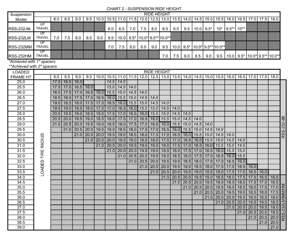
52 Configuration cont. Back to Table of Contents. Ride height. Measured from the center of the wheel to the bottom of frame, ride height is related to frame height, which is ground to bottom of frame, by the following formula: Ride Height = Frame Height - Loaded Tire Radius The typical loaded radius for a given tire size can be found in Chart. The frame height or ride height must be measured at the location that the auxiliary suspension is to be installed and when the vehicle is on level ground and loaded. If it is not possible to load the vehicle, the loaded frame deflection must be approximated to ensure that the auxiliary suspension operates within its designed ride height range. Consult the vehicle manufacturer or body builder s guide for further information. The model RSS-3 suspension will accommodate the following ride heights: a. 3,00 lb capacity to 8.0 inches. These ride heights are covered by 3 different models, 3LM (low mount), 3MM (mid mount), and 3HM (high mount). b. 8,000 lb capacity to 6.5 inches. One model, 3-8k, covers this entire range. Chart shows the relationship between frame height and ride height and the models that will accommodate each. Suspensions must operate within their designed ride height. The model RSS-3 suspension requires a guide to position the hanger properly on the frame for a given ride height. Either the air spring plate can serve as this guide or an installation tool is available. See Figure. All RSS-3 suspensions can be spaced down or inches for maximum versatility and performance. The installation of a spacer requires a change from the standard 8 inch bolting rail height (the portion of the hanger extending above the bottom of the frame). Predrilled holes easily locate the air spring plate or installation tool for the correct bolting rail height. Fasteners are provided. See Figure 3a and 3b. 4

53 5


54 6

55 Configuration cont. Back to Table of Contents 3. Axle to driveline clearance. Measured from the top of the axle to the bottom of the driveline when the axle is in the lifted position. It is recommended that clearance be maintained between the axle and the driveline at all times during vehicle operation. Additional driveline clearance of to inches can be gained by spacers installed during suspension installation. See section Ride Height for more information. Chart 3 provides the bottom of frame to top of lifted axle dimensions for each model. 4. Wheel ends. The model RSS-3 can be ordered for use with hub pilot or stud pilot wheels. Light weight hubs and drums and drums for use with 9.5 wheels are also available in hub pilot versions. 5. Operating in reverse. The RSS-3 is a self-steer suspension but will only do so when the vehicle is traveling forward. There are two ways to control the auxiliary axle when the vehicle is placed in reverse: a. Lift-in-reverse operation - A signal is sent to the air controls to lift the suspension when the reverse lights are activated. The air controls must be ordered with this feature. b. Steer-lock operation - This option is preinstalled on the axle and locks the wheels in the straight ahead position when the vehicle is in reverse. Installation Procedures. After reading the Pre-Installation Notes and Configuration section of this manual, determine and mark the proper location of the suspension. The frame must be clear in this location for proper suspension fit-up. A cross member must be located within 6 of the leading or trailing edge of the hanger.. Measure the vehicle frame width and make adjustments as necessary to the suspension frame width. Variations of +/-/4 inch from the nominal frame width settings (34, 34.5, and 35.0 inches) do not require changes to the shim washers. See Configuration, frame width for more information. Temporarily secure the cross channel in place with a single bolt in the slotted hole. 3. With the air spring plate or installation tool bolted to the inside of the hangers (see Configuration, ride height for more information), locate the hangers on the frame and clamp them firmly into place. The air spring plate or installation tool must be contacting the bottom of the frame. Ensure that the hangers are evenly located for proper axle alignment (fore and aft) and square to the frame. Also, the top of the hanger must be parallel to the bottom of the frame within / degree to maintain proper caster angle. Care should be taken to ensure that the hangers are precisely located and clamped tightly into place before drilling holes. 7

56 Installation Procedures cont. 4. Center punch and drill total /3 inch holes in the locations shown in Figure 4. If it is not possible to use the recommended bolt locations, the total number fasteners must be maintained. Spacing groups of fasteners apart as far as possible provides the greatest strength. Use caution when drilling near wires, hoses or other components located within the frame rail. Bolt the hangers and air spring plates to the frame with total 5/8 inch grade 8 bolts and prevailing torque lock nuts. Hardened washers or flanged fasteners are required. 5. Remove the air spring plate or installation tool from the hanger. Locate the air spring plates at the dimension shown in Figure 4 and clamp them firmly into place. The spacer, if required, must also be clamped into place between the air spring plate and the frame rail. A 3/4 and a / inch fastener can be used to temporarily secure the spacer to the air spring plate through the air spring mounting holes. A dimension of.88 inches from the top of the hanger to the top of the air spring plate should be held at all times, with or without air spring spacers. Center punch and drill 4 total /3 inch holes in the locations shown in Figure 4 and install 4 total 5/8 inch grade 8 bolts and prevailing torque lock nuts. Hardened washers or flanged fasteners are required. 6. Assemble the load air springs to the air spring plates. 7. Ensure that the hangers have remained parallel during installation. Drill 8 total 3/3 inch holes in the hanger cross channel using the pre-drilled pilot holes. Bolt the hanger cross channels using the 3/8 fasteners provided. 8. Install the air controls as required using 3/8 air lines. Refer to the installation drawing or air control manual for more information. 9. Ensure that all fasteners are tightened to the specified torque in Chart 4. 8
57 Back to Table of Contents 9
58 Back to Table of Contents Installation Check. Reduce the air pressure to the load springs to below 0 psi. Operate the suspension up and down to ensure proper operation and suspension clearance to other components. Check that the driveline has adequate clearance when the suspension is lifted.. Check that the suspension either lifts or that the steer locks straighten the wheels when the vehicle is placed in reverse. 3. Check the toe of the suspension. See Toe Setting for more details. 4. Check that all fasteners, including wheel nuts, are tightened to the proper torque values. 5. Check that brakes and slack adjusters are properly adjusted and that wheels rotate freely. 6. Check hubs for proper oil levels. Toe Setting Toe is the difference between the dimensions, measured at spindle height, across the front of the tires versus the rear as shown in Figure 5. Therefore, TOE = REAR FRONT. If FRONT is less than REAR, the suspension has toe-in. The toe of the suspension is critical to ensure proper tracking of the wheels, long tread life, stability and smooth operation. If there are problems with any of these items, the first thing to check is the toe. Toe is pre-set at the factory but there may be times that it must be checked in the field. Check and Adjustment:. Deflate the air pressure from all air springs.. Raise the axle and support it with jack stands and ensure the tires are pointing straight ahead. 3. While spinning the tires, mark the center tread with chalk. 4. Measure the distances between tires, from the edges of the marked tread and at spindle height, as shown in Figure 5. TOE = REAR FRONT. The toe should be between /3 and 3/3. 5. The toe can be adjusted by loosening the clamps on both ends of the tie rod, twisting the rod forward or rearward to achieve the proper toe dimension, and retightening the clamps to 50 ft-lbs. Bushing Replacement Notes Bushings can be replaced with simple hand tools. Inner bushing sleeves must be greased with all-purpose grease prior to assembly. It is recommended that washers and bushings be replaced at the same time. Refer to Figure for the correct washer locations. 0
59 Back to Table of Contents T ' I ' I ' I ' I p CY <:;: :~ CY D LL ' ~ ~ ~

60 Suspension Operation The controls of the RSS-3 should include a switch or push/pull knob to raise or lower the suspension, depending upon vehicle load carrying requirements, and a pressure regulator with gage to control the load carried by the suspension. The operator must be aware of the amount of pressure required to support a given load carried by the auxiliary suspension. Chart 5 shows the approximate air pressure, as shown on the gage, required to support a given load. To obtain a more accurate correlation, place scales under the lowered auxiliary axle and, while adjusting the gage pressure, read and make note of the load on the scales.
61 Back to Table of Contents Maintenance Schedule To keep your Ridewell suspension in optimum working order, we recommend following maintenance. 3

62 Back to Table of Contents 4

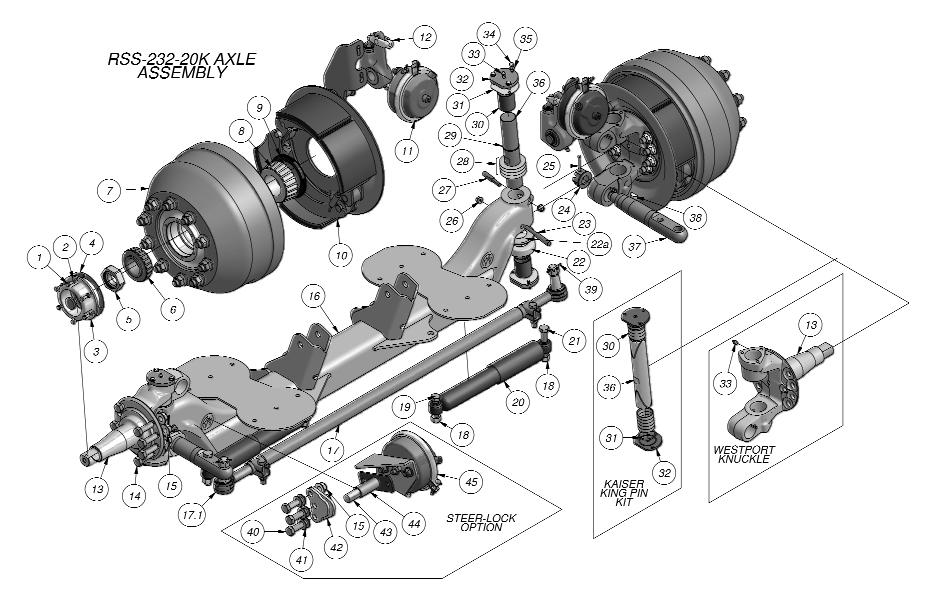
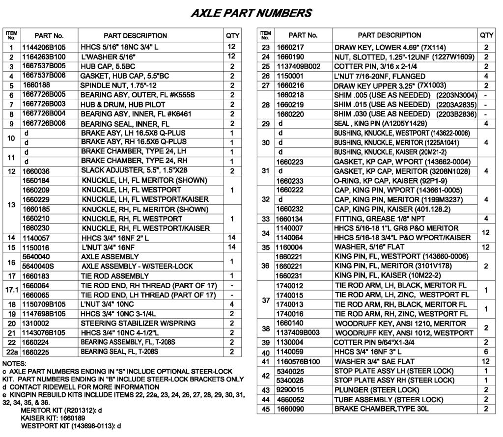
63 Back to Table of Contents Axle Assembly OPTIONAL STEER-LOCK (SHOWN STREET SIDE ONLY) ITEM PART NO , ,, 64638, , 9 0 I I, BEARING, WHEEL, / 4K OUTER BEARING, WHEEL, 8K OUTER 0 HUB AND DRUM, BEARING, WHEEL. /4K INNER BEARING, WHEEL, 8K INNER BEARING SEAL, INNER /4K BEARING SEAL, INNER BK 0 BRAKE ASM LH 35X00, SLX&CBR BRPKE ASM RH 5X4, 45' BRAKE ASM RH J5X I 00, SLK&CBR , "'"'"' "'"' "'"'"' "' J , , I HUB CAP. 6K HHCS 5/ s 8NC 3/4" L L 'WASHER 5/ 6* GASKET, HUB CPP. /4K GASKET, HUB CPP. 8K SPINDLE NUT r W/NUT CLIP SPINDLE NUT /8 NF 0 DESCRIPTION HUB CAP, /4(.,"', B I I 8Nf " L 0Nf.5" L 8Nf TOP LK 0Nf flanged TIE ROO ARM LH, 3.K TIE ROO ARM LH, BK TIE ROO ARM RH, 3.K TIE ROO ARM RH, 8K TIE ROO ASSEMBLY / 4K SHIM.05. F"C (AS REQ'O) SHIM.00". rc; (AS REQ'O) 0 SHIM.00"". 6&0.36 SHIM.005", > ( ) 30J04 rc rc (AS REQ'O) (AS REQ'O) SHIM fc (.AS REO'D) GASKET, KING PIN CI'P, fg GASKET, KING PIN CI'P,.oos. rc CAP, KING PIN, FG CAP, KING PIN, FC (03D94) (03K300) (803G633) NA (0.3L300) (803H034) (306M07) ( ) (97T475) (97F640) FlniNG, GREASE /8.. f\ PTF" (99N660) HHCS 5/6" 6NC "L GR6 (S-5BP-) (9(669) WASHER 5/6" SAE FLAT WOODRUff KEY.6\ISI 0 (6X035) AKLE RSS J 8K ~4 ""g 4J BRAKE CHAMBER. TYPE 0L TUBE ASSEMBLY, STEER LOCK 44 9Q005 I PLUNGER. STEER-LOCK L'NUT 5/8" 8NF TOP LK STOP PLATE, STEER-LOCK RSS HHCS 5/8" 8NF 3/4" WASHER 5/8" SAE/A-35 NA NA NA NA NA e; Iii I ~~ AXL RSS-.3LM w 6& I If) ::;;:::: :::.:,,..., "'"' "'"'I (5) (5) <..> KING PIN. f"c KING PIN, fg B BEARING, THRUST, fc BEARING, THRUST, fc T-6S (80356) (8V530) CREASE SEAL, 3K KING PIN (05X48) CREASE SEAL, 8K KING PIN (05TJJ+) ORAVI KEY 7/6 0NF 3.88L(7X ) ORAVI KEY 7/6" 0NF 3.68L(7K00) L'NUT 7/6" 0NF FLANGEO (7Z760) NUT. CASTL -/8.. Nf" (7)(60) COTIER PIN 3/6 >: -/4 (K 68) I KNUCKLE RH, FG KNUCKLE RH, FC 5/8* /* S/8" /" 5 I HHCS HHCS L'NUT L'NUT 4 I rc KNUCKLE LH, I Ill ITEM PART NO. HHCS 3/4.. 0NC 3 3/4..L GR5 I ~~ DESCRIPTION HHCS 3/4" 0NC 4-/"L GR5.,3 ~ "' "' "'"' "'"' I BR!>J<E ASM LH 5K4, 45 BR!>J<E CHAMBER,TYPE 0L BR!>J<E CHOMBER,TYPE SLACK ASSEMBLY KNUCKLE LH, FG.,"' J:.,.., "'"'I "'"' AKLE RSS 3MM/HM ~ TIE ROO ASSEMBLY 8K L"NUT 3/4"" 0NC OVAL 3/4'" HI HHCS 3/4" 0NC STEERING STABILIZER NOTES: o CONTACT RIDEWELL OR REFER TO AN INSTALLATION DRAWING FOR MORE DETAILS b J.J<LE NUMBERS WITH AN s" SUFFlX INCLUDE STEER-LOCK (SHOWN STREET SIDE ONLY) /4L C RIDEWELL KING PIN REBUILD KITS: RSS-3-8K: RSS-3LM,MM,HM: KITS INCLUDE: 5,6,7,8,3,J,J3,J4,35,J6,JS,J9 & BEARING
64 Warranty Back to Table of Contents Ridewell Suspensions warrants the suspension systems manufactured by it to be free from defects in material and workmanship, under proper use, installation, application, and maintenance for period of 3 years after delivery to the original purchaser. The responsibility of Ridewell Suspensions under this warranty is limited to making good at the company factory by repair or replacement of any part or parts which it manufactures. Written permission for any claim return must be first obtained from Authorized Ridewell personnel. All returns must have transportation charges prepaid by the customer and accompanied with a complete written explanation of claimed defects and the circumstances of operational failure. On all component parts not manufactured by Ridewell, their warranty is to the extent that the manufacturer of such parts warrant them to Ridewell Suspensions. This is the only authorized warranty and is in lieu of all other expressed or implied warranties or representations, including any implied warranties of merchantability or fitness, or of any obligations on the part of Ridewell Suspensions. In no event will Ridewell be liable for business interruptions, loss of profits, personal injury, cost of delay, or for other special, indirect, incidental or consequential losses, costs or damages. Subject to all of the above conditions, if repair or replacement of any defective part is made by Ridewell Suspensions, Ridewell will return the repaired or replaced part to the original purchaser with transportation charges prepaid. - months - 36 months 00% Parts & Labor 00% Parts Only
65
66 CONTENTS Pre-Installation Notes...Pg Configuration...Pg 3 Installation Procedures...Pg 6 Installation Check...Pg 8 Suspension Operation...Pg 8 Maintenance Schedule...Pg 9 Parts Illustrations...Pg 0 Warranty...Pg SUSPENSION IDENTIFICATION: Ridewell Suspensions are identified by a metal tag attached to the left-hand hanger that indicates part number, revision level, and serial number. PARTS: For optimum suspension performance, order only Ridewell parts. Replacement parts for Model RSS-3-0K are shown on pages 0 & of this manual. SALES, SERVICE & WARRANTY: If you need assistance regarding this product, please contact us and we will be glad to help you. Mailing Address Shipping Address Phones, Fax, Ridewell Corporation Ridewell Corporation , (47) P.O. Box E. Farm Rd. 94 (47) , fax Springfield, MO Springfield, MO info@ridewellcorp.com Pre-Installation Notes. Suspensions are designed to operate within specific parameters. Operating the suspension outside the design parameters may result in improper performance, damaged equipment, and void of warranty. See the Configuration section of this manual.. The total operating capacity of a suspension is determined by the component with the lowest load rating. Please consult with the manufacturers of tires and wheels to determine the maximum suspension system capacity. 3. Improperly locating an auxiliary suspension on a vehicle can unload or overload the vehicle s primary suspensions. The installer is responsible to ensure the auxiliary suspension is properly located for correct load distribution. 4. The installer is responsible to ensure that all local, state, and federal bridge laws are satisfied regarding axle spacing and capacity in the location where the vehicle is to be used before installing an auxiliary suspension. 5. The installer is responsible to ensure that air reservoir volume requirements are met. Consult the vehicle manufacturer or Federal Motor Vehicle Safety Standards (FMVSS) for more information. 6. If vehicle chassis modifications are required, consult with the vehicle manufacturer to ensure that such changes are permitted. 7. Welding or altering suspension components is not permitted except where explicitly stated by Ridewell Corp. 8. The installer is responsible to ensure that there is sufficient clearance to the auxiliary suspension, tires, air springs, axle (including axle to driveline) and steering components. 9. When lowering an auxiliary axle on an unloaded vehicle, pressure to the load air springs must be reduced to below 0 psi. Failure to do so could cause the vehicle s drive axles to rise from the ground causing the vehicle to roll away.

67 Configuration Back to Table of Contents The Ridewell model RSS-3-0K suspension is designed with flexibility in mind so that one suspension fits as many vehicle configurations as possible while maximizing suspension performance. Each suspension must be configured to meet the following parameters before installation:. Frame width: All model RSS-3-0K suspensions can be configured to accommodate truck frame widths from 33.5 to 35.0 inches. Suspensions can be ordered with pre-set frame widths or can be field modified. Frame width adjustments are made by loosening the cross-channel, removing the axle end of the lower torque rods, removing the hanger end of the upper torque rods and moving the shim washer(s) of each torque rod from one side to the other. The proper location for the shim washers for a given frame width can be found in Figure. Ensure that all fasteners are properly retightened. Do not weld cross-channel. 3

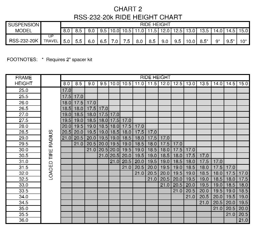
68 Configuration cont.. Ride height: Measured from the center of the wheel to the bottom of frame, ride height is related to frame height, which is ground to bottom of frame, by the following formula: Ride Height = Frame Height - Loaded Tire Radius The typical loaded radius for a given tire size can be found in Chart. The frame height or ride height must be measured at the location on the vehicle that the auxiliary suspension is to be installed and with the vehicle loaded and on level ground. If it is not possible to load the vehicle, the loaded frame deflection must be approximated to ensure that the auxiliary suspension operates within its designed ride height range. Consult the vehicle manufacturer or body builder s guide for further information. The model RSS-3-0K suspension will accommodate ride heights of 8 to 5 with a single model. Ride heights of 3.5 to 5 require the optional spacer kit. Chart shows the relationship between frame height and ride height. Suspensions must operate within their designed ride height range. 3. Axle to driveline clearance: Measured from the top of the axle to the bottom of the driveline when the axle is in the lifted position. It is recommended that clearance be maintained between the axle and the driveline at all times during vehicle operation. Additional driveline clearance of inches can be gained by spacers installed during suspension installation. See section Ride Height for more information. The bottom of frame to top of lifted axle dimension is 8.5 without spacers or 0.5 with the spacer kit. 4. Operating in reverse: The RSS-3 is a self-steer suspension but will only do so when the vehicle is traveling forward. There are two ways to control the auxiliary axle when the vehicle is placed in reverse: a. Lift-in-reverse operation - A signal is sent to the air controls to lift the suspension when the reverse lights are activated. The air controls must be ordered with this feature. b. Steer-lock operation - This option is preinstalled on the axle and locks the wheels in the straight ahead position when the vehicle is in reverse. 4

69 5

70 Installation Procedures Back to Table of Contents. After reading the Pre-Installation Notes and Configuration section of this manual, determine and mark the proper location of the suspension on the chassis. The frame must be clear in this location for proper suspension fit-up. A cross member must be located within 6 of the leading or trailing edge of the hanger.. Measure the vehicle frame width and make adjustments as necessary to the suspension frame width. See Configuration, frame width for more information. The spacer kit, if required, must also be installed at this time. To facilitate fit up, slots on the hanger and air spring plate align with tabs on the spacer kit. Weld the spacers solid to the suspension with /4 fillet welds. All welds must stop /4 to / before edges. 3. Locate the hangers on the frame and clamp them firmly into place. The shelf at the top of the hanger must fully contact the bottom of the frame. Ensure that the hangers are evenly located for proper axle alignment (fore and aft) and square to the frame. Care should be taken to ensure that the hangers are precisely located and clamped tightly into place before drilling holes. 4. Center punch and drill total /3 inch holes in the locations shown in Figure 3. If it is not possible to use the recommended bolt locations, the total number fasteners must be maintained. Spacing groups of fasteners apart as far as possible provides the greatest strength. Use caution when drilling near wires, hoses or other components located within the frame rail. Bolt the hangers to the frame with total 5/8 inch grade 8 bolts and prevailing torque lock nuts. Hardened washers or flanged fasteners are required. 5. Locate the air spring plates at the dimension shown in Figure 3 and clamp them firmly into place. The air spring plate must be in full contact with the bottom of the frame. Center punch and drill 8 total /3 inch holes in the locations shown in Figure 3 and install 8 total 5/8 inch grade 8 bolts and prevailing torque lock nuts. Hardened washers or flanged fasteners are required. 6. Install the cross-channel, if necessary, and ensure all bolts are properly tightened to the torque listed in Chart Install the air controls as required using 3/8 air lines. Refer to the installation drawing or air control manual for more information. 6
71 7

72 Installation Check Back to Table of Contents. Reduce the air pressure to the load springs to below 0 psi. Operate the suspension up and down to ensure proper operation and suspension clearance to other components. Check that the driveline has adequate clearance when the suspension is lifted.. Check that the suspension either lifts or that the steer locks straighten the wheels when the vehicle is placed in reverse. 3. Check the toe of the suspension. Toe-in should be /3 +/-/3. 4. Check that all fasteners, including wheel nuts, are tightened to the proper torque values. 5. Check that brakes and slack adjusters are properly adjusted and that wheels rotate freely. 6. Check hubs for proper oil levels. Suspension Operation The controls of the RSS-3 should include a switch or push/pull knob to raise or lower the suspension, depending upon vehicle load carrying requirements, and a pressure regulator with gauge to control the load carried by the suspension. The operator must be aware of the amount of pressure required to support a given load carried by the auxiliary suspension. Chart 4 shows the approximate air pressure, as shown on the gauge, required to support a given load. To obtain a more accurate correlation, place scales under the lowered auxiliary axle and, while adjusting the gauge pressure, read and make note of the load on the scales. 8
73 Maintenance Schedule Back to Table of Contents To keep your Ridewell suspension in optimum working order, we recommend following maintenance. 9

74 Parts Illustrations Back to Table of Contents 0
75
76 Warranty Back to Table of Contents Ridewell Suspensions warrants the suspension systems manufactured by it to be free from defects in material and workmanship, under proper use, installation, application, and maintenance for period of 3 years after delivery to the original purchaser. The responsibility of Ridewell Suspensions under this non-transferable warranty is limited to making good at the company factory by repair or replacement of any part or parts which it manufactures. Written permission for any claim return must be first obtained from Authorized Ridewell personnel. All returns must have transportation charges prepaid by the customer and accompanied with a complete written explanation of claimed defects and the circumstances of operational failure. On all component parts not manufactured by Ridewell, their warranty is to the extent that the manufacturer of such parts warrant them to Ridewell Suspensions. This is the only authorized warranty and is in lieu of all other expressed or implied warranties or representations, including any implied warranties of merchantability or fitness, or of any obligations on the part of Ridewell Suspensions. In no event will Ridewell be liable for business interruptions, loss of profits, personal injury, cost of delay, or for other special, indirect, incidental or consequential losses, costs or damages. Subject to all of the above conditions, if repair or replacement of any defective part is made by Ridewell Suspensions, Ridewell will return the repaired or replaced part to the original purchaser with transportation charges prepaid. - months 00% Parts & Labor 3-4 months 00% Parts Only 5-36 months 50% Parts Only
77 RSS-3-8K & RSS-3-3K Ride Height Chart 8,000 lb. & 3,00 lb. Capacity Self-Steer Axle Truck Suspensions Model Part Number Series 3-8K 380 3LM-3K 30 3MM-3K 30 3HM-3K 303 FOOTNOTES: LIFT a 0 a 9.5 b 0 b LIFT a 0 a 9.5 b 0 b LIFT a 0 a 9.5 b 0 b LIFT a 0 a 9.5 b 0 b a Achieved with " spacers y Ride height range is 3.5" to 6.5" b Achieved with " spacers z Ride height range is 5.75" to 8.75" LM=Lo-Mount MM=Mid-Mount HM=Hi-Mount T=Trailer Ride Height Frame Height Ride Height FOOTNOTES: 9.5" wheels requrie special brake drums 7.5" x 6" wide x 5" offset/4.5" inset 6 stud wheels required. Available through Ridewell as part number or LOADED TIRE RADIUS RSS-3-3k.5" & 9.5" WHEELS RSS-3-8k 7.5" WHEELS
78 RSS-3-0K & RSS-3T-0K Ride Height Chart 0,000 lb. Capacity Self-Steer Lift Axle Truck Suspensions Trailer Suspensions Weld-on / Bolt-on Model Ride Height Part Number Series K 3300_ LIFT a 8.5 a 9.0 a 9.5 a 3R-0K 3303_ LIFT RO-0k 3304_ LIFT LMT-0k 350 / 353 LIFT MMT-0k 35 / 354 LIFT HMT-0k 35 / 355 LIFT FOOTNOTES: a Requires " spacer kit LM=Lo-Mount MM=Mid-Mount HM=Hi-Mount T=Trailer Ride Height Frame Height LOADED TIRE RADIUS


79 RCA-5 & RUL-45 Non-Steerable Auxiliary Axle Suspensions For trucks RCA-5,500 lb. capacity Designed for the aftermarket installer with built-in flexibility RUL-45I 3,00 lb. capacity For I-beam axles with permanently locked tie rods RUL-45R 3,00 lb. capacity For 5 round axles, straight or drop Durable, lightweight FiberTech TM bushing Secure axle connection without u-bolts Easily adjusts to various frame widths & ride heights Easy axle alignment system Axle integration optional
80 RCA-5 & RUL-45 Non-Steerable Auxiliary Axle Suspensions RCA-5 Features Wide beam spacing reduces axle stress Shock kit option available Fits ride heights 7½ to 6 0¼ total travel; up to 7 of lift Axle alignment adjustment 3 /8 at each hanger Accepts axle drop up to 8 RUL-45 Features Lightweight, compact design fits tight spaces Can incorporate an I-beam or round axle 45I fits ride heights 6 3 /8 to 4 45R fits ride heights to 7½ Up to ½ total travel; up to 8½ of lift (with I-beam axle) Axle alignment adjustment 3 /8 at each hanger Accepts axle drop up to 8 (with round axle) Air Controls Manual & Electric Wide range of custom options available
81


82 RCA-5 Flex-Mount TM Auxiliary Axle Suspension Owner s Manual P.O. Box 4586 Springfield, MO (fax) 07
83 RCA-5 Auxiliary Axle Owner s Manual Contents Pre-Installation Notes...3 Configuration Installation Procedures Axle Integration...9 Installation Check...9 Suspension Operation...9 Bushing Check Procedure... Bushing Replacement Procedure...-3 Maintenance Schedule...4 Warranty...4 Parts Illustration...5 Suspension Identification: Ridewell Suspensions are identified by a metal tag attached to the left-hand hanger that indicates part number, revision level, and serial number. Consult your vehicle manufacturer for your correct mounting height. Parts: For optimum suspension performance, order only Ridewell parts. Replacement parts for Model RCA-5 are shown on page 5 of this manual. Sales, Service & Warranty: If you need assistance regarding this product, please contact us and we will be glad to help you. Mailing Address Ridewell Corporation P.O. Box 4586 Springfield, MO Shipping Address Ridewell Corporation 375 East Farm Rd. 94 Springfield, MO Phones, Fax, , (fax) info@ridewellcorp.com
84 RCA-5 Auxiliary Axle Owner s Manual Pre-Installation Notes. Suspensions are designed to operate within specific parameters. Operating the suspension outside the design parameters may result in improper performance, damaged equipment, and void of warranty.. The total operating capacity of a suspension is determined by the component with the lowest load rating. Please consult with the manufacturers of tires, wheels, axles, and brakes to determine the maximum suspension system capacity. The RCA-5 suspension is rated for,500 lbs. 3. Improperly locating an auxiliary suspension on a vehicle can unload or overload the vehicle s primary suspensions. The installer is responsible for ensuring the auxiliary suspension is properly located for correct load distribution. 4. The installer is responsible for ensuring that all local, state, and federal bridge laws are satisfied regarding axle spacing and capacity in the location where the vehicle is to be used before installing an auxiliary suspension. 5. The installer is responsible for ensuring that air reservoir volume requirements are met. Consult the vehicle manufacturer or Federal Motor Vehicle Safety Standards (FMVSS) for more information. 6. If vehicle chassis modifications are required, consult with the vehicle manufacturer to ensure that such changes are permitted. 7. Welding or altering suspension components is not permitted except where explicitly stated by Ridewell Corporation. 8. The installer is responsible for ensuring that there is sufficient clearance to the auxiliary suspension, tires, air springs, and axle (including axle to driveline). 9. When lowering an auxiliary axle on an unloaded vehicle, pressure to the load air springs must be reduced to below 0 psi. Failure to do so could cause the vehicle s drive axles to rise from the ground causing the vehicle to roll away. 3


85 RCA-5 Auxiliary Axle Owner s Manual Configuration The Ridewell model RCA-5 suspension is designed with flexibility in mind so that one suspension fits as many vehicle configurations as possible while maximizing suspension performance. Each suspension must be configured to meet the following parameters before installation:. Frame width - All model RCA-5 suspensions can be configured to accommodate frame widths from 33.5 to 35.0 inches. Frame widths are set by the location to which the beam is welded to the axle. See Figure.. Ride height - Measured from the center of the wheel to the bottom of frame, ride height is related to frame height, which is ground to bottom of frame, by the following formula: Ride Height = Frame Height - Loaded Tire Radius The typical loaded radius for a given tire size can be found in Chart. The frame height must be measured at the location that the auxiliary suspension is to be installed and when the vehicle is on level ground and loaded. If it is not possible to load the vehicle, the loaded frame deflection must be approximated to ensure that the auxiliary suspension operates within its designed ride height range. Consult the vehicle manufacturer or body builder s guide for further information. 4


86 Back to Table of Contents RCA-5 Auxiliary Axle Owner s Manual Chart shows the relationship between frame height and ride height and the models that will accommodate each. Suspensions must operate within their designed range of ride heights. Spacing - All RCA-5 truck suspensions can be spaced down or inches for maximum versatility and performance with spacer kits available through Ridewell. The hangers and air springs must be spaced equal amounts. Air spring brakets must be removed and discarded. The new air spring plates with spacer must be fastened using the / nut from the discarded bracket and the 3/4 nut in the spacer kit. The hanger spacers are located by a pilot hole in each hanger and are welded into place. See Figures and 3 for more details. 5

87 RCA-5 Auxiliary Axle Owner s Manual 3. Axle to driveline clearance - Measured from the top of the axle at the center of the drop section to the bottom of the driveline when the axle is in the lifted position. It is recommended that clearance be maintained between the axle and the driveline at all times during vehicle operation. Additional driveline clearance of to inches can be gained by spacers installed during suspension installation. See Section, Ride Height, for more information. 4. Shocks - Optional shock kits are available through Ridewell. The upper shock brackets bolt to the frame and the lower brackets are welded to the axle at the forward and rear edge with a 5/6 weld. Do not weld perpendicular to the axle centerline. See Figure 4 for installation details. 6
88 RCA-5 Auxiliary Axle Owner s Manual Installation Procedures. After reading the Pre-Installation Notes and Configuration sections of this manual, determine and mark the proper location of the suspension. The frame must be clear in this location for proper suspension fit-up. A cross member must be located within 6 of the leading or trailing edge of the hanger. It is also recommended that a cross member be located above the main air spring.. If the suspension has not been welded or bolted to the axle, see the Axle Integration section of this manual. 3. Locate the hangers on the frame and clamp them firmly into place. The hanger or hanger spacer must contact the bottom of the frame at the leading and trailing edge. Ensure that the hangers are evenly located for proper axle alignment (fore and aft) and square to the frame. Care should be taken to ensure that the hangers are precisely located and clamped tightly into place before drilling holes. 4. Center punch and drill 6 total /3 inch holes, 8 in each hanger, in the locations shown in Figure 5. Always maintain hole centers at above the bottom of the frame and below the top of the bolting rail whether spacers are used or not. Use caution when drilling near wires, hoses or other components located within the frame rail. Bolt the hangers to the frame with 6 total 5/8 inch grade 8 bolts and prevailing torque lock nuts. Hardened washers or flanged fasteners are required. 5. Locate the air spring plate at the dimension shown in Figure 5 and clamp them firmly into place. The air spring or spacer must have full contact to the bottom of the frame. If spacers are required, hangers and air springs must be spaced equal amounts. Center punch and drill or 4 total /3 inch holes in the frame. Install 5/8 inch grade 8 bolts and prevailing torque lock nuts. Hardened washers or flanged fasteners are required. 7


89 RCA-5 Auxiliary Axle Owner s Manual FIGURE 6 SPEED SET TM ALIGNMENT FEATURE NOTICE: ALIGNMENT PLATE MUST BE ADJUSTED FULLY REARWARD AND THEN MOVED FORWARD AS NECESSARY FOR ALIGNMENT. IMPORTANT: THE TWO PLATES ON EACH HANGER MUST BE MOVED EQUAL AMOUNTS OR LOSS OF PIVOT BOLT TORQUE MAY OCCUR. TORQUE: ½" NUTS TO FT-LBS; PIVOT BOLT NUT TO 500 FT-LBS. RIDEWELL CORPORATION SPRINGFIELD, MO USA # Rev.B 6. Assemble the load air springs to the air bracket or air spring plates. 7. Ensure that the hangers have remained parallel during installation. Bolt the hanger crosschannels using the / fasteners provided. 8. Align the suspension per TMC or SAE recommended standards. Alignment should be done with the suspension at the required ride height. Ensure the alignment plates are adjusted rearward fully at both hangers and moved forward as necessary. The two adjustment plates on each hanger must be moved equal amounts or loss of pivot bolt torque may occur. Torque all alignment fasteners to the values shown on the alignment label. See Figure 6. Note: It is imperative that the pivot nuts be fully tightened prior to placing the suspension into service to avoid damage to the suspension. Failure to torque the pivot nuts will void warranty. 9. Ensure that all fasteners are tightened to the specified torque in Chart Install the air controls as required. Refer to the installation drawing or air control manual for more information. CHART 3 - TORQUE SPECIFICATIONS FASTENER TORQUE SIZE LOCATION FT-LBS N-M 3/8"-6NC LOAD AIR SPRING 5 34 /"-3NC LIFT AIR SPRING 5 34 /"-3NC ALIGNMENT PLATE /4"-6NF LOAD AND LIFT AIR SPRING /8"-4NF PIVOT BOLT
90 RCA-5 Auxiliary Axle Owner s Manual Axle Integration. Locate the suspension beams on the axle with the correct frame width between hangers. The beams must be parallel and the axle centered between the beams. For drop center axles, locate the brake cam rearward and /4 off the rear plate of the beam; straight axles require that the cam be located forward and /4 off the top of the beam.. All axles should be clamped to the beam prior to integration. Check the gap between the axle and axle seat. The gap at the welded edge should be no greater than /8 wide. The gap at the bottom of the seat, both inboard and outboard, should be zero (see the illustration at the bottom of Weld Process #). 3. Weld the axle to the beams per Ridewell Weld Process # which is included in this manual. If the lift air springs are assembled to the suspension, they should be covered to protect them from weld spatter. Installation Check. Reduce the air pressure to the load springs to below 0 psi. Cycle the suspension up and down to ensure proper operation and suspension clearance to other components. Check that the driveline has adequate clearance when the suspension is lifted.. Check that all fasteners, including wheel nuts, are tightened to the proper torque values. 3. Check that brakes and slack adjusters are properly adjusted and that wheels rotate freely. 4. Check hubs for proper oil levels. Suspension Operation The controls of the RCA-5 should include a switch or push/pull knob to raise or lower the suspension and a pressure regulator with gage to control the load. The operator must be aware of the amount of pressure required to support a given load. Chart 4 shows the approximate air pressure, as shown on the gage, required to support a given load. To obtain a more accurate correlation, place scales under the lowered auxiliary axle and, while adjusting the gage pressure, read and make note of the load on the scales. 9
91 RCA-5 Auxiliary Axle Owner s Manual.5 MAX ROOT PASS.38 SECOND PASS 0.50 THIRD PASS AXLE AXLE AXLE 0.50 AXLE BEAM AXLE SEAT BEAM AXLE SEAT BEAM AXLE SEAT WELD JOINT PREPARATION FIRST PASS SECOND PASS BEAM AXLE SEAT THIRD PASS ARC START ARC START 3.0 NO WELD TOP OF AXLE ARC STOP THIRD PASS SECOND PASS ARC STOP THIRD PASS SECOND PASS FIRST PASS FIRST PASS 4.0 NO WELD BOTTOM OF AXLE.0 TYP.0 TYP NO WELDING ZONE SMAW GMAW / FCAW REPRESENTATIVE AXLE SEAT (PROFILE DEPENDENT ON SUSPENSION PRODUCT) - WELD JOINT PREPARATION: ALL GREASE, DIRT, PAINT, SLAG OR OTHER CONTAMINANTS MUST BE REMOVED FROM THE WELD JOINT WITHOUT GOUGING THE AXLE TUBE. INSURE THE LOWER BEAM ASSEMBLY FITS THE AXLE WITH A ROOT GAP OF 0.5 INCH MAXIMUM BETWEEN THE AXLE AND THE BEAM AXLE SEAT AS ILLUSTRATED ABOVE. IT IS RECOMMENDED TO C-CLAMP THE AXLE TO AXLE BEAM SEAT PRIOR TO WELDING TO INSURE THAT PROPER CONTACT OCCURS BETWEEN THE AXLE AND THE BEAM SEAT. SEE ILLUSTRATION BELOW. - WELDING PRECAUTIONS: ALL WELDS MUST BE KEPT AWAY FROM THE TOP AND BOTTOM OF THE AXLE WHERE MAXIMUM STRESSES OCCUR. THE "NO WELD" ZONES ARE ILLUSTRATED ABOVE. DO NOT TEST WELD THE ARC ON ANY PART OF THE AXLE TUBE. THIS CAN LEAD TO A SMALL CRACK THAT MAY EVENTUALLY GROW AND AFFECT THE FATIGUE LIFE OF THE AXLE. 3 - ALL WELDERS AND WELDING OPERATORS SHOULD BE CERTIFIED PER AMERICAN WELDING SOCIETY (AWS) D. SECTION 5 PROCEDURES OR EQUAL. 4 - RECOMMENDED WELDING METHODS ARE SHIELDED METAL ARC (SMAW (STICK)), GAS METAL ARC (GMAW (SOLID WIRE)), OR FLUX CORED ARC (FCAW (FLUX WIRE)) WELDING. WHATEVER ELECTRODE AND METHOD USED MUST DEVELOP A MINIMIMUM WELD TENSILE STRENGTH OF 70,000 P.S.I. REFER TO THE ELECTRODE MANUFACTURER'S RECOMMENDATION FOR VOLTAGE, CURRENT AND SHIELDING MEDIUM FOR THE DIAMETER ELECTRODE TO BE USED SO THE BEST FUSION AND MECHANICAL PROPERTIES CAN BE OBTAINED. RECOMMENDED ELECTRODE IS E708 IF SMAW IS USED. RECOMMENDED ELECTRODE IS E70S- OR E70T- IF GMAW OR FCAW WELDING IS USED. 5 - ALL ELECTRODES USED SHOULD MEET AWS SECTION 5 SPECIFICATIONS AND CLASSIFICATIONS FOR WELDING CARBON AND LOW ALLOY STEELS. 6 - IF SMAW ELECTRODES (STICK) ARE USED, THEY MUST BE NEW, DRY, FREE OF CONTAMINANTS AND COME FROM A STOCK THAT HAS BEEN PURCHASED AND STORED PER AWS SECTION 4.5., LOW HYDROGEN ELECTRODE STORAGE SPECIFICATIONS. 7 - GROUND THE AXLE TO ONE OF THE ATTACHED AXLE PARTS SUCH AS THE AIR CHAMBER BRACKETS, CAM BRACKETS OR BRAKE SPIDER. NEVER GROUND THE AXLE TO A WHEEL OR HUB AS THE SPINDLE BEARING MAY SUSTAIN DAMAGE. 8 - THE AXLE ASSEMBLY SHOULD BE AT A MINIMUM TEMPERATURE OF 60 DEGREES F (5 DEGREES C) PRIOR TO WELDING. PRE-HEATING THE WELD ZONE TO THE AXLE MANUFACTURER'S PRE-HEAT TEMPERATURE IS RECOMMENDED. THIS WILL MINIMIZE THE FORMATION OF MARTENSITIC OR BRITTLE METAL STRUCTURES IN THE FUSION LINE OR THE HEAT AFFECTED ZONE WHICH MAY CONTRIBUTE TO A PREMATURE FATIGUE FAILURE IN SERVICE. 9 - THE JOINT TO BE WELDED SHOULD BE POSITIONED IN THE FLAT OR HORIZONTAL POSITION. 0 - MULTIPLE PASS WELDING SHOULD BE USED ON THE BEAM/AXLE CONNECTION USING THE FOLLOWING GUIDELINES. TOTAL FILLET WELD SIZE SHOULD BE 0.5 INCH. - MULTIPLE PASS WELD INITIATION AND TERMINATION SHOULD BE PERFORMED AS SHOWN ABOVE. ALL SLAG MUST BE REMOVED BETWEEN PASSES. BACKSTEP FILL ALL CRATERS. EACH PASS MUST BE ACCOMPLISHED IN ONE OR TWO SEGMENTS. NEVER START OR STOP WELDS AT THE END OF THE WELD JOINT. START WELDS AT LEAST " FROM END AND BACKWELD OVER THE START. WELDS MUST GO TO WITHIN /8" +/- /6" OF THE ENDS OF THE AXLE SEAT AND MUST NOT GO BEYOND OR AROUND THE ENDS. - POST-WELD PEENING (RECOMMENDED, BUT NOT REQUIRED): NEEDLE PEEN THE ENTIRE TOE OF THE SECOND PASS, INCLUDING AROUND THE ENDS OF THE AXLE SEAT. HOLD THE NEEDLES PERPENDICULAR TO THE AXLE. A UNIFORM DIMPLED PATTERN WILL APPEAR WHEN PROPERLY PEENED..5 MAX CORRECT INCORRECT APPLICABLE SUSPENSION MODELS: 00, 5, 40, 45R, 5, 43, 60. C 00 REVISED WELD DIMENSIONS. 6/5/0 G.H. MDJ CJB B 00 REVISED NOTES AND. /3/0 G.H. MDJ CJB A 0700 ADDED 5 TO LIST OF SUSPENSION MODELS COVERED /6/07 G.H. MDJ DK REV PROJECT DESCRIPTION DATE BY CHK APPD DRAWN BY: CHECKED: APPROVED: PROJECT NO: 0303 MATERIAL: CBC 6/3/00 MDJ //003 CJB //003 - SCALE: A-SIZE: NTS WEIGHT: - TITLE: R SHEET OF RIDEWELL CORPORATION PO BOX 4586 SPRINGFIELD, MISSOURI RIDEWELL WELD PROCESS #, 5" DIA. AXLE, 3 PASS WELD PART NO: WELD PROCESS # REV: C 0
92 RCA-5 Auxiliary Axle Owner s Manual Bushing Check Procedure The bushings in the RCA-5 suspension should be checked during any scheduled maintenance or if there is a suspected problem. The bushings should be checked if any of the following conditions are observed:. Uneven tire wear.. Any abnormal fwd-aft or lateral movement of the axle during operation. 3. Rapid degradation of the wear washers. 4. Any abnormal noises coming from the suspension. To check, insert the flat end of a pry-bar between the sidewall of the hanger and the eye of the beam. Applying moderate side load to the pry-bar, look for any relatively large or easy movement of the beam in relation to the hanger. Note that a small amount of movement under load due to deflection of the rubber is normal and acceptable. Repeat the process on the other side of the hanger. If large or easy movement is noted, drop the beams down per the bushing replacement procedure for further inspection of the bushing and replace if necessary.
93 RCA-5 Auxiliary Axle Owner s Manual Bushing Replacement Procedure Order Ridewell part number for RCA-5 bushing replacement kit. Bushing removal and installation requires FiberTech bushing press tool Contact Ridewell for more information on obtaining these items.. Chock the wheels and secure the vehicle. Lift the auxiliary axle, remove the wheels, block up the axle and deflate the air springs. Remove the lift air spring, shock absorbers (if installed), and disassemble the load air spring top plate.. Remove pivot nuts and bolts and rotate trailing arm beams down and out of hangers. It is not necessary to remove the alignment plates. 3. Inspect pivot holes and hanger surfaces for unusual wear or damage. Repair or replace components as required. 4. Lubricate the threads and bearings of the FiberTech bushing press tool, part number Lubricate liberally inside the cylinder of the press tool with P80 lubricant or a soap solution. Petroleum lubricants must not come in contact with the bushing. 5. Assemble the bushing press tool to the bushing and beams as shown in the Removal portion of Figure 7 and ensure it is centered in the beam eye. Rotate the hex head of the threaded shaft with an impact wrench to press out the old FiberTech bushing. 6. Disassemble the bushing press tool. 7. Clean the bushing eye of corrosion and debris. 8. Apply P80 rubber lubricant or a soap solution to the new bushing outer diameter, inside the beam eye and the tool cylinder to ease installation. 9. Reassemble the bushing press tool as shown in the Installation portion of Figure 7 and ensure it is centered in the eye. Rotate the hex head of the threaded shaft with an impact wrench to install a new FiberTech bushing. 0. Remove the bushing press tool and ensure the bushing is centered between the ridges of the beam eye.. Install new thrust washers on both sides of the new bushing and rotate the beams into the hangers.. Install new pivot bolts and nuts and tighten to the torque shown in Chart Reassemble the suspension in reverse order from above.

94 RCA-5 Auxiliary Axle Owner s Manual 3

95 RCA-5 Auxiliary Axle Owner s Manual Maintenance Schedule Warranty The Ridewell Corporation warrants the suspension systems manufactured by it to be free from defects in material and workmanship, under proper use, installation, application, and maintenance for a period of 3 years after delivery to the original purchaser. The responsibility of the Ridewell Corporation under this warranty is limited to making good at the company factory by repair or replacement of any part or parts which it manufactures. Written permission for any claim return must be first obtained from authorized Ridewell personnel. All returns must have transportation charges prepaid by the customer and accompanied with a complete written explanation of claimed defects and the circumstances of operational failure. On all component parts not manufactured by Ridewell their warranty is to the extent that the manufacturer of such parts warrant them to Ridewell Corporation. This is the only authorized Ridewell warranty and is in lieu of all other expressed or implied warranties or representations, including any implied warranties of merchantability or fitness, or of any obligations on the part of Ridewell Corporation. In no event will Ridewell be liable for business interruptions, loss of profits, personal injury, cost of delay, or for any other special, indirect, incidental or consequential losses, costs or damages. Subject to all of the above conditions, if repair or replacement of any defective part is made by Ridewell Corporation, Ridewell will return the repaired or replaced part to the original purchaser with transportation charges prepaid. 4 months 00% parts & labor 3 36 month 00% parts only

96 Back to Table of Contents RCA-5 Auxiliary Axle Owner s Manual 5
97


98 RUL-45 Bantamweight Auxiliary Liftable Air-Rides for Truck & Trailer Applications Owner s Manual P.O. Box 4586 Springfield, MO (fax) 07
RD-202S. Heavy-Duty Tandem Drive Truck Suspension Owner s Manual
 RD-202S Heavy-Duty Tandem Drive Truck Suspension Owner s Manual www.ridewellcorp.com P.O. Box 4586 Springfield, MO 65808 47.833.4565 47.833.4560 (fax) 073 Suspension Identification: Ridewell Suspensions
RSS K Truck Self-Steering Auxiliary Axle Suspension
 RSS-233-10K Truck Self-Steering Auxiliary Axle Suspension Installation and Service Manual Suspension Identification... 2 Suspension System Serial Tag Installation... 3 Torque Specifications Prior to Installation
RSS K Truck Self-Steering Auxiliary Axle Suspension
 RSS-233-13K Truck Self-Steering Auxiliary Axle Suspension Installation and Service Manual Suspension Identification... 2 Suspension System Serial Tag Installation... 3 Torque Specifications Prior to Installation
RSS K Truck Self-Steering Air-Ride Suspension
 RSS-233-20K Truck Self-Steering Air-Ride Suspension Installation and Service Manual Suspension Identification... 2 Suspension System Serial Tag Installation... 3 Prior to Installation Suspension Mounting
RSS-232/232T - 8K-10K-13K Self-Steering Auxiliary Axle Suspension
 RSS-232/232T - 8K-10K-13K Self-Steering Auxiliary Axle Suspension Installation and Service Manual Suspension Identification... 2 Suspension System Serial Tag Installation... 3 Prior to Installation Suspension
RSS-232/232T 20K Truck and Trailer Self-Steering Auxiliary Axle Suspension
 RSS-232/232T 20K Truck and Trailer Self-Steering Auxiliary Axle Suspension RSS-232 - Truck suspension shown Installation and Service Manual Suspension Identification... 2 Suspension System Serial Tag Installation...
RSS-233T - 13K Trailer Self-Steering Air-Ride Suspension
 RSS-233T - 13K Trailer Self-Steering Air-Ride Suspension Installation and Service Manual Suspension Identification... 2 Suspension System Serial Tag Installation... 3 Torque Specifications Prior to Installation
RSS-233T - 13K Trailer Self-Steering Air-Ride Suspension
 RSS-233T - 13K Trailer Self-Steering Air-Ride Suspension Installation and Service Manual Suspension Identification... 2 Suspension System Serial Tag Installation... 3 Torque Specifications Prior to Installation
RSS Truck Suspension Self-Steer Air-Ride Suspension System for Customer-Supplied I-Beam Axle
 RSS-2361000-Truck Suspension Self-Steer Air-Ride Suspension System for Customer-Supplied I-Beam Axle Installation and Service Manual Suspension Identification... 2 Suspension System Serial Tag Prior to
RSS-233T - 20K Trailer Self-Steering Air-Ride Suspension
 RSS-233T - 20K Trailer Self-Steering Air-Ride Suspension Installation and Service Manual Suspension Identification... 2 Suspension System Serial Tag Installation... 3 Prior to Installation Suspension Mounting
OWNER S GUIDE 8A DURALIFT II 13,200 LB. CAPACITY. Link Mfg. Ltd th St. N.E. Sioux Center, IA USA
 OWNER S GUIDE 8A000715 DURALIFT II 13,200 LB. CAPACITY Link Mfg. Ltd. 223 15th St. N.E. Sioux Center, IA USA 51250-2120 www.linkmfg.com QUESTIONS? CALL CUSTOMER SERVICE 1-800-222-6283 DEALER / INSTALLER:
RAR Lightweight Trailer Suspension Owner s Manual. P.O. Box 4586 Springfield, MO
 RAR-243 Lightweight Trailer Suspension Owner s Manual www.ridewellcorp.com P.O. Box 4586 Springfield, MO 65808 417.833.4565 417.833.4560 (fax) 0711 Suspension Identification: Ridewell Suspensions are identified
TAG LIFT AXLE SUSPENSION SERVICE MANUAL- 37 T
 TAG LIFT AXLE SUSPENSION SERVICE MANUAL- 37 T ` Page 0 CONTENT SI.NO Description Page No. 1 Suspension Specification 2 2 Pre-Installation Notes 2 3 Suspension Parts Description 3 4 Dismantling Procedure
TECHNICAL PROCEDURE NON-STEERABLE SUSPENSION SYSTEMS
 TECHNICAL PROCEDURE NON-STEERABLE SUSPENSION SYSTEMS SUBJECT: Installation Instructions LIT NO: DATE: December 2003 TABLE OF CONTENTS Introduction... 2 Required Supplies... 2 Pre-Installation Checklist...
INSTALLATION INSTRUCTIONS
 INSTALLATION INSTRUCTIONS 8A000729 DuraLift 13.5 13,500 LB. CAPACITY Link Mfg. Ltd. 223 15th St. N.E. Sioux Center, IA USA 51250-2120 www.linkmfg.com QUESTIONS? CALL CUSTOMER SERVICE 1-800-222-6283 Refer
INSTALLATION MANUAL TOYOTA TUNDRA 5 SUSPENSION SYSTEM PART # 55905
 PART NUMBER : 55905 1999 2003 TOYOTA TUNDRA 5 SUSPENSION SYSTEM PARTS LIST: Part # Description Qty. 55900-01 Driver Side Spindle 1 55900-02 Passenger Side Spindle 1 55905-03 Rear brake proportioning valve
JOHN DEERE 9970 COTTON PICKERS
 PARTS CATALOG FOR Mud Hog System II Rear Wheel Drive FOR JOHN DEERE 9970 COTTON PICKERS Mud Hog Model Numbers Tread Center OEM Aftermarket JD40005 JD47655 82, 90, 94, 106 TUTHILL Drive Systems 9098 West
RideStar RHP Series Sliding Tandem Trailer Air Suspension System
 Maintenance Manual 14S RideStar RHP Series Sliding Tandem Trailer Air Suspension System Revised 05-14 Service Notes About This Manual This manual provides the correct lubrication, service and installation
INSTALLATION MANUAL TOYOTA TACOMA 5 SUSPENSION SYSTEM PART # 54900
 PART NUMBER : 54900 1996 2004 TOYOTA TACOMA 5 SUSPENSION SYSTEM PARTS LIST: Part # Description Qty. 55900-01 Driver Side Spindle 1 55900-02 Passenger Side Spindle 1 54900-01 Rear brake proportioning valve
SUSPENSION 2-1 SUSPENSION TABLE OF CONTENTS
 XJ SUSPENSION 2-1 SUSPENSION TABLE OF CONTENTS page ALIGNMENT... 1 FRONT SUSPENSION... 7 page REAR SUSPENSION... 16 ALIGNMENT TABLE OF CONTENTS page AND WHEEL ALIGNMENT...1 DIAGNOSIS AND TESTING SUSPENSION
OWNER S MANUAL. LOEGERING th Street SE Casselton, ND USA Fax:
 OWNER S MANUAL TRAIL BLAZERS and D SERIES TRACKS LOEGERING 800-373-5441 15514 37 th Street SE 701-347-5441 Casselton, ND 58012 USA Fax: 701-347-4323 E-Mail: lmi@loegering.com Internet: www.loegering.com
TRAILER INSTALLATION INSTRUCTIONS
 TRAILER INSTALLATION INSTRUCTIONS 8A000450 DuraMax 20,000 LB. CAPACITY Link Mfg. Ltd. 223 15th St. N.E. Sioux Center, IA USA 51250-2120 www.linkmfg.com QUESTIONS? CALL CUSTOMER SERVICE 1-800-222-6283 Refer
RAR Stub Axle Suspension Trailer Air-Ride Suspension
 RAR-251 - Stub Axle Suspension Trailer Air-Ride Suspension Installation and Service Manual Suspension Identification... 2 Suspension System/Axle Serial Tag Installation... 3 Prior to Installation Axle
OWNER S MANUAL Z SERIES TRACKS. Rev. 355_05
 OWNER S MANUAL Z SERIES TRACKS Rev. 355_05 LOEGERING 800-373-5441 15514 37 th Street SE 701-347-5441 Casselton, ND 58012 USA Fax: 701-347-4323 E-Mail: lmi@loegering.com Internet: www.loegering.com Loegering
Air Ride Single Point Suspension. Installation and Service Manual
 RAR-254 Air Ride Single Point Suspension Installation and Service Manual Suspension Identification... 2 Suspension System/Axle Serial Tag Installation... 3 Prior to Installation Suspension Mounting Troubleshooting
SUSPENSION 2-1 SUSPENSION TABLE OF CONTENTS
 DN SUSPENSION 2-1 SUSPENSION TABLE OF CONTENTS page ALIGNMENT... 1 FRONT SUSPENSION - 4x2... 6 page FRONT SUSPENSION - 4x4... 14 REAR SUSPENSION... 23 ALIGNMENT TABLE OF CONTENTS page AND OPERATION WHEEL
Refer to separate Installation Instructions for installation details.
 OWNER S GUIDE 8A000729 DuraLift 13.5 13,500 CAPACITY Link Mfg. Ltd. 223 15th St. N.E. Sioux Center, IA USA 51250-2120 www.linkmfg.com QUESTIONS? CALL CUSTOMER SERVICE 1-800-222-6283 DEALER / INSTALLER:
FRONT DRIVELINE MODIFICATION MAY BE NECESSARY!!!!
 INSTALLATION INSTRUCTIONS FOR 2009 DODGE 2500/3500 4WD & 1500 Mega Cab 6 SUSPENSION SYSTEM PART NUMBER 7206 Requires the following parts (sold separately) for a complete installation: Front Coil Spring
INSTALLATION MANUAL 4.5 I.F.S. SUSPENSION CURR. FORD F150 W/4.2 OR 4.6 LITER PART # 24940
 INSTALLATION MANUAL 4.5 I.F.S. SUSPENSION 1997- CURR. FORD F150 W/4.2 OR 4.6 LITER PART # 24940 SJ101402 PART NUMBER : 24940 1997 CURR. FORD F150 W/4.2 OR 4.6 LITER 4.5 SUSPENSION SYSTEM WITH FRONT SPINDLES
Independent Front Suspension
 Independent Front Suspension Technical Training Contents Why Independent? Tuthill Models Features and Benefits Description Special Tools Regular Maintenance Troubleshooting Available Kits Contacting Tuthill
Operation and Maintenance Manual for. Joyce/Dayton Linear Actuator Pound Capacity AC Actuator (with limit switch and potentiometer)
") Joyce/Dayton Corp. Operation and Maintenance Manual for Joyce/Dayton Linear Actuator 1500 Pound Capacity AC Actuator (with limit switch and potentiometer) WARNING! The recommendations in this manual for
Joyce/Dayton Corp. Operation and Maintenance Manual for Joyce/Dayton Linear Actuator 1500 Pound Capacity AC Actuator (with limit switch and potentiometer) WARNING! The recommendations in this manual for
Part # Jeep Grand Cherokee/Wagoneer 4WD 3 Lift Now Manufactured with Chromolly Arms PRO COMP SUSPENSION. Suspension Systems that Work!
 PRO COMP SUSPENSION Suspension Systems that Work! Important: Vehicles equipped with light duty, double offset joint (rubber boot) front driveshafts must be replaced with splicer constant velocity (CV)
4, 6 Suspension System. Ford F250/350 4WD Part#: ,
 Part#: 013411, 013611 4, 6 Suspension System Ford F250/350 4WD 2005-2007 Rev. 071917 491 W. Garfield Ave., Coldwater, MI 49036. Phone: 517-279-2135 E-mail: tech-bds@sporttruckusainc.com Read And Understand
INSTALLATION INSTRUCTIONS FOR FORD 4WD SUPER DUTY F COIL SPRING SUSPENSION SYSTEM
 INSTALLATION INSTRUCTIONS FOR 2008-10 FORD 4WD SUPER DUTY F250-350 6 COIL SPRING SUSPENSION SYSTEM Requires the following parts (sold separately) for a complete installation: KIT PART NUMBER (6860) REQUIRES
Installation manual 3 suspension system Toyota Tacoma 4 x 4 & PreRunner Part # sj rev.03
 Part #: 52904 1995-2004 Toyota Tacoma 4 x 4 & PreRunner 3 suspension system Parts list: Part # Description Qty. 52904-01 Rear brake proportioning valve bracket 1 52907-02 Front pre load spacer 2 52904-03
INSTALLATION INSTRUCTIONS QA1 P/N x400, x500, x600, x400, x500, x F100 Front Coil-over Suspension System
 INSTALLATION INSTRUCTIONS QA1 P/N 52620-x400, 52620-x500, 52620-x600, 52621-x400, 52621-x500, 52621-x600 65-72 F100 Front Coil-over Suspension System TOOLS AND SUPPLIES REQUIRED Floor Jack Two (2) Jack
Heavy Duty Front-Drive Steer Axles MX-140 and MX-160 Series
 Revised 11/2009 Heavy Duty Front-Drive Steer Axles MX-140 and MX-160 Series Catalog PB-0349 Strength Power Speed Agility MERITOR PARTS. RIGHT FROM THE START. TABLE OF CONTENTS MX-17/19/21-140 and MX-21/23-160
INSTALLATION INSTRUCTION 88148
 INSTALLATION INSTRUCTION 88148 Rev C For Rancho Suspension Systems RS6548, RS6549 & RS6550: GM 2500HD, 2500, and 1500HD Trucks READ ALL INSTRUCTIONS THOROUGHLY FROM START TO FINISH BEFORE BEGINNING INSTALLATION
SUSPENSION 2-1 SUSPENSION CONTENTS
 DN SUSPENSION 2-1 SUSPENSION CONTENTS page ALIGNMENT... 1 FRONT SUSPENSION... 5 page REAR SUSPENSION... 13 ALIGNMENT INDEX page GENERAL INFORMATION WHEEL ALIGNMENT... 1 DIAGNOSIS AND TESTING PRE-ALIGNMENT
CHEVY / GMC 1500HD / 2500HD 2WD 8 LUG 7 BASIC KIT
 85101 2000-2010 CHEVY / GMC 1500HD / 2500HD 2WD 8 LUG 7 BASIC KIT C8510-4 MAIN BOX KIT W/ HARDWARE 1) FRONT X MEMBER 1) REAR X MEMBER 2) TORSION BAR DROPS 1) LEFT BUMP STOP 1) RIGHT BUMP STOP 2) SWAY BAR
WARNING!!! READ AND UNDERSTAND ALL INSTRUCTIONS BEFORE PROCEEDING. MAKE SURE THAT YOU HAVE ALL TOOLS AND PARTS BEFORE BEGINNING THE INSTALLATION.
 INSTALLATION INSTRUCTIONS FOR 2007-2015 JEEP JK 3 SUSPENSION LIFT SYSTEM PART NUMBER 587 WARNING!!! READ AND UNDERSTAND ALL INSTRUCTIONS BEFORE PROCEEDING. MAKE SURE THAT YOU HAVE ALL TOOLS AND PARTS BEFORE
PARTS CATALOG FOR. Mud Hog Rear Wheel Drive FOR. MF 9540/9550/9560, CAT 540C/550C/560C, Gleaner A540/A560, Fendt 6450R/9480R COMBINES
 PARTS CATALOG FOR Mud Hog Rear Wheel Drive FOR MF 9540/9550/9560, CAT 540C/550C/560C, Gleaner A540/A560, Fendt 6450R/9480R COMBINES Mud Hog Model Number: AG9896 A Product of Tuthill Drive Systems P.O.
MS2200, MS2500, and MS3000 Suspension Installation Manual ON/OFF HIGHWAY SUSPENSION SYSTEM
 MS22, MS25, and MS3 Suspension Installation Manual ON/OFF HIGHWAY SUSPENSION SYSTEM 972.547.62 8.445.736 FAX: 972.542.97 725 E. UNIVERSITY ST. McKINNEY, TEXAS 7569 www.watsonsuspensions.com Watson & Chalin
Installation manual. 3 suspension system Toyota Tacoma. Part # Part # Important customer information: Toyota Tacoma
 Installation manual 3 suspension system 2005 2008 Toyota Tacoma Part # 52907 sj111607rev.02 Part # 52907 2005-2008 Toyota Tacoma 3 suspension system Part # Description Qty. 52907-01 Pre-load spacer 2 52907-02
INSTALLATION MANUAL 4 I.F.S. SUSPENSION CURR. CHEVY SUBURBAN / YUKON XL (WITH 5 LINK REAR END) PART # 14965
 PART # 14965") PART NUMBER : 14965 2000 CURR. SUBURBAN W/ REAR COIL SPRINGS 4 SUSPENSION SYSTEM WITH FRONT SPINDLES PARTS LIST: Part # Description Qty. C4I1SN-07 Passenger Side Differential Drop 1 C4I1SN-23 Driver Side
PART NUMBER : 14965 2000 CURR. SUBURBAN W/ REAR COIL SPRINGS 4 SUSPENSION SYSTEM WITH FRONT SPINDLES PARTS LIST: Part # Description Qty. C4I1SN-07 Passenger Side Differential Drop 1 C4I1SN-23 Driver Side
Ford Super Duty Recoil Traction Bar System. Part#: ,123409
 Part#: 123418,123409 Ford Super Duty Recoil Traction Bar System Rev. 011017 491 W. Garfield Ave., Coldwater, MI 49036. Phone: 517-279-2135 Web/live chat: www.bds-suspension.com. E-mail: tech-bds@sporttruckusainc.com
DISC BRAKE/DUAL MASTER CYLINDER CONVERSION. Tools, Equipment and Supplies Needed:
 Please take the time to read the enclosed instructions carefully. If you have any questions, call our Product Assistance personnel for clarification. It is important to note that these instructions contain
DODGE DIESEL KIT DODGE DIESEL KIT
 69120 2009-2013 DODGE 2500 8 DIESEL KIT 2009-2012 DODGE 3500 8 DIESEL KIT Heavy Duty Long Arm Construction For Superior Ride Quality And Travel Lower Arms Constructed Of 1.75 DOM Tubing W/ Urethane Bushing
Model 86/88. Suspension System. Installation and. Maintenance Instructions
 Model 86/88 Suspension System Installation and Maintenance Instructions Drawing - 213N Installation Instructions Models 86/88 m.3 Suspension System ReycoGranning Models 86 & 88 Parts List Drawing No. 2I3N
UPPER TRAILING ARM REMOVAL
 #1204 MUSTANG UPPER TRAILING ARMS Thank you for your purchase. Please call us at (562) 907-7757 if you have any questions regarding your Hotchkis Performance products. Visit us online @ www.hotchkis.net
INSTALLATION MANUAL 6 I.F.S. SUSPENSION CURR. CHEVY HEAVY DUTY WD PART # / WITH OUT SHOCKS PART # / WITH SHOCKS
 INSTALLATION MANUAL 6 I.F.S. SUSPENSION 2001 - CURR. CHEVY HEAVY DUTY 2500 2WD PART # 16987 / WITH OUT SHOCKS PART # 16988 / WITH SHOCKS SJ031502 Tuff Country EZ-Ride Suspension highly recommends that
INSTALLATION INSTRUCTION 88051
 INSTALLATION INSTRUCTION 88051 For Rancho Suspension System RS6551: Chevrolet 2500 Suburban & 2500 Avalanche READ ALL INSTRUCTIONS THOROUGHLY FROM START TO FINISH BEFORE BEGINNING INSTALLATION Rev C IMPORTANT
Maintenance and Parts Manual ADZ Series Suspension
 Maintenance and Parts Manual ADZ Series Suspension XL-PS10452MM-en-US Rev C Contents Contents Page Introduction... 3 Warranty... 3 Notes, Cautions, and Warnings... 3 Section 1 General Safety Instructions...
INSTALLATION INSTRUCTION 88146
 INSTALLATION INSTRUCTION 88146 Rev H FOR RANCHO SUSPENSION SYSTEM RS6547: 4WD SUBURBAN/YUKON XL, 4WD TAHOE/YUKON, & 4WD AVALANCHE READ ALL INSTRUCTIONS THOROUGHLY FROM START TO FINISH BEFORE BEGINNING
2. Remove front wheels.
 1 PARTS DIAGRAM 2 Installation Instructions: (PASSENGER SIDE) 1. Place jack under center of RUV front end and lift until front wheels clear the ground. Be careful to support the RUV properly so that it
INSTALLATION INSTRUCTION 88045
 INSTALLATION INSTRUCTION 88045 Rev B FOR RANCHO SUSPENSION SYSTEM RS6545: CHEVROLET SILVERADO READ ALL INSTRUCTIONS THOROUGHLY FROM START TO FINISH BEFORE BEGINNING INSTALLATION IMPORTANT NOTES! WARNING:
Technical Support Line: (952) Hanover Ave. Lakeville, MN
 Hanover Ave. Lakeville, MN") Technical Support Line: (952) 985-5675 Email: Sales@QA1.net 21730 Hanover Ave. Lakeville, MN 55044 www.qa1.net INSTALLATION INSTRUCTIONS QA1 1967-1979 Mopar A-Body Rear 6 link Conversion System QA1 p/n
Technical Support Line: (952) 985-5675 Email: Sales@QA1.net 21730 Hanover Ave. Lakeville, MN 55044 www.qa1.net INSTALLATION INSTRUCTIONS QA1 1967-1979 Mopar A-Body Rear 6 link Conversion System QA1 p/n
Ford Super Duty Recoil Traction Bar System. Part#: ,
 Part#: 123408, 123409 Ford Super Duty Recoil Traction Bar System Rev. 090817 491 W. Garfield Ave., Coldwater, MI 49036. Phone: 517-279-2135 E-mail: tech-bds@sporttruckusainc.com Read And Understand All
2.5" & 3.5" SUSPENSION SYSTEM
 2.5" & 3.5" SUSPENSION SYSTEM 2007-2014 JEEP JK WRANGLER 2 & 4 DOOR MODELS JSPEC2352 www.jksmfg.com jks@sporttruckusainc.com 517-278-1226 Rv. 071814 Getting Started Read all warnings, instructions, notes
INSTALLATION MANUAL 6 I.F.S. SUSPENSION CHEVY OR GMC 1500 SILVERADO PART # 16955
 INSTALLATION MANUAL 6 I.F.S. SUSPENSION 1999-2003 CHEVY OR GMC 1500 SILVERADO PART # 16955 sj031203rev.01 PART NUMBER : 16955 1999 2003 CHEVY 1500 PICK UP 6 SUSPENSION SYSTEM WITH FRONT SPINDLES Part #
SUSPENSION 2-1 SUSPENSION CONTENTS
 WJ SUSPENSION 2-1 SUSPENSION CONTENTS page ALIGNMENT... 1 FRONT SUSPENSION... 4 page REAR SUSPENSION... 15 ALIGNMENT INDEX page AND WHEEL ALIGNMENT... 1 SERVICE PROCEDURES PRE-ALIGNMENT... 2 AND WHEEL
Detroit Speed, Inc. Detroit Speed Control Arm and Spindle Kit A-Body P/N: &
 Detroit Speed, Inc. Detroit Speed Control Arm and Spindle Kit 1964-72 A-Body P/N: 030104 & 030105 The Detroit Speed A-Body front suspension kit is a bolt-on package that addresses the shortcomings of the
SUSPENSION 2-1 SUSPENSION CONTENTS
 ZJ SUSPENSION 2-1 SUSPENSION CONTENTS page ALIGNMENT... 1 FRONT SUSPENSION... 6 page REAR SUSPENSION... 14 ALIGNMENT INDEX page GENERAL INFORMATION WHEEL ALIGNMENT... 1 DIAGNOSIS AND TESTING SUSPENSION
INSTALLATION MANUAL. CNH 5088, 6088, 7088 and 5130, 6130, 7130
 INSTALLATION MANUAL FOR Mud Hog Rear Wheel Drive FOR CNH 5088, 6088, 7088 and 5130, 6130, 7130 COMBINES Mud Hog Model Number: CNH42005 A Product of Tuthill Drive Systems P.O. Box 600 Brookston, Indiana
IS INDEPENDENT SUSPENSION SYSTEM OWNERS MANUAL
 IS INDEPENDENT SUSPENSION SYSTEM OWNERS MANUAL * Made in U.S.A. Patent number 5899470 IS153-002 REV. 1 Description Congratulations on your purchase of the MOR/ryde IS suspension system*. The MOR/ryde IS
Torque Settings INSTALLATION MANUAL 3 I.F.S. SUSPENSION TOYOTA TACOMA PART # 52904
 INSTALLATION MANUAL 3 I.F.S. SUSPENSION 1995-2002 TOYOTA TACOMA PART # 52904 SJ010702 PART NUMBER : 52904 1995-2002 TOYOTA TACOMA 3 SUSPENSION SYSTEM PARTS LIST: Part # Description Qty. TT212-02 Rear Brake
Model 66/660* Actuator for Trailer Brakes 6,600 lbs Capacity Drum Brake Ready or Disc Brake Ready US Patent No. 6,375,211
 Installation Instructions and Service Manual Model 66/660* Actuator for Trailer Brakes 6,600 lbs Capacity Drum Brake Ready or Disc Brake Ready US Patent No. 6,375,211 *Model 660 - Manufactured after March
Installation Instructions
 Equipment Required: Fastener Kit: F Wrenches: 3/4, 15/16 Drill Bits: 1/4 Other Tools: Drill Short & Long Bed All Megacabs 9464/9474 HIDE-A-GOOSE HITCH INSTALLATION WARNING: Under no circumstances do we
Installation manual. 4.5 suspension system June 2007 Dodge Ram 2500 / Part # Part # Important customer information:
 Installation manual 4.5 suspension system 2003 - June 2007 Dodge Ram 2500 / 3500 Part # 34003 sj11407rev.03 Part # 34003 2003 - June 2007 Dodge Ram 2500 / 3500 4.5 suspension system Part # Description
12-1/4 x 3-1/2 Electric Wheel Brake
 12-1/4 x 3-1/2 Electric Wheel Brake A-216 819-0244 Installation Instructions An Altra Industrial Motion Company Contents Dimensions.... 2 Technical Specifications.... 3 Installation Instructions General....
JEEP WRANGLER (YJ) 4 LEAF SPRING KIT TM w/ Power Steering & TM w/ Manual Steering
 4 LEAF SPRING KIT TM w/ Power Steering & TM w/ Manual Steering") 400 W. Artesia Blvd. Fax: (310) 747-3912 Compton, CA 90220 Ph: (877) 695-7812 www.trailmastersuspension.com JEEP WRANGLER (YJ) 4 LEAF SPRING KIT 87-96 TM3540-20013 w/ Power Steering & TM3540-20023 w/ Manual
400 W. Artesia Blvd. Fax: (310) 747-3912 Compton, CA 90220 Ph: (877) 695-7812 www.trailmastersuspension.com JEEP WRANGLER (YJ) 4 LEAF SPRING KIT 87-96 TM3540-20013 w/ Power Steering & TM3540-20023 w/ Manual
RS NO: SUBJECT:
 RS-340 Thru 520 NO: SUBJECT: Springing: Frame Hangers, Load Cushions and Saddle Assembly EFFECTIVE DATE: July 1993 REVISION: E CONTENTS Item Subject Page 1 Introduction 2 2 Important Safety Notice 2 3
(877) MON-FRI 7AM-5PM PST OR WEBSITE: ReadyLIFT.COM **Please retain this document in your vehicle at all times**
 MON-FRI 7AM-5PM PST OR WEBSITE: ReadyLIFT.COM **Please retain this document in your vehicle at all times**") IF YOUR ReadyLIFT PRODUCT IS MISSING A OR HAS A DAMAGED PART, PLEASE CONTACT CUSTOMER SERVICE DIRECTLY. For warranty issues please return to the place of installation and contact ReadyLIFT. A NEW REPLACEMENT
IF YOUR ReadyLIFT PRODUCT IS MISSING A OR HAS A DAMAGED PART, PLEASE CONTACT CUSTOMER SERVICE DIRECTLY. For warranty issues please return to the place of installation and contact ReadyLIFT. A NEW REPLACEMENT
Tools, Equipment and Supplies Needed:
 153-162 DISC BRAKE/DUAL MASTER CYLINDER CONVERSION Please take the time to read the enclosed instructions carefully. If you have any questions, call our Product Assistance personnel for clarifi cation.
Operation and Maintenance Manual for. Joyce/Dayton Linear Actuator Pound Capacity DC Actuator, LA152L, and LA152C
 Joyce/Dayton Corp. Operation and Maintenance Manual for Joyce/Dayton Linear Actuator 1500 Pound Capacity DC Actuator, LA152L, and LA152C WARNING! The recommendations in this manual for installation, operation
PARTS LIST AAT230/250 INTRAAX TRAILER SUSPENSION SYSTEM
 PARTS LIST AAT30/0 INTRAAX TRAILER SUSPENSION SYSTEM LIT NO: 974-0 DATE: March 06 REVISION: A SECTION PAGE Introduction... Axle and Suspension Identification... 3 Axle ID Plate... 3 Suspension Assembly
1. General Description
 General Description 1. General Description A: SPECIFICATION Front Rear Model Wheel arch height (Tolerance: +12 mm 24 mm ( +0.47 in 0.94 in)) mm (in) 376 (14.8) Camber (Tolerance: 0 45 Differences between
2.5" & 3.5" SUSPENSION SYSTEM JEEP JK WRANGLER 2 & 4 DOOR MODELS
 2.5" & 3.5" SUSPENSION SYSTEM 2007-2018 JEEP JK WRANGLER 2 & 4 DOOR MODELS JSPEC2352 www.jksmfg.com jks@ridefox.com 517-278-1226 RV. 100818 GETTING STARTED Read all warnings, instructions, notes and cautions
INSTALLATION MANUAL 4 I.F.S. SUSPENSION SYSTEM DOOR TAHOE / LUG PART # 14830
 INSTALLATION MANUAL 4 I.F.S. SUSPENSION SYSTEM 1992-1998 2 DOOR TAHOE / 1500 6 LUG PART # 14830 SJ100702 PART NUMBER : 14830 1992-1998 / 2 DOOR TAHOE / 1500 6 LUG 4 SUSPENSION SYSTEM WITH FRONT SPINDLES
Hydraulic Wheel Dolly
 Hydraulic Wheel Dolly Operating Instructions & Parts Manual Model Number HW93765 Capacity 3/4 Ton Made in the U.S.A. This is the safety alert symbol. It is used to alert you to potential personal injury
Installation manual. 3.5 suspension system Chevy / GMC 2500HD / 3500HD With contact overloads Part # 13090
 Part # 13090 2011-2016 Chevy / GMC 2500HD / 3500HD With contact overloads 3.5 suspension system Part # Description Qty. 13085-01 DS & PS Upper control arm 2 13085-02 DS & PS Front upper shock bracket 2
INSTALLATION AND MAINTENANCE MANUAL
 IMPORTANT This manual must accompany the trailer when delivered to the end user. INSTALLATION AND MAINTENANCE MANUAL ISS Series Suspensions 347 King Street West, Ingersoll, Ontario, Canada, N5C 3K6 Ph:
INSTALLATION INSTRUCTION 88581
 INSTALLATION INSTRUCTION 88581 FOR RANCHO SUSPENSION SYSTEM RS6581B: DODGE RAM READ ALL INSTRUCTIONS THOROUGHLY FROM START TO FINISH BEFORE BEGINNING INSTALLATION Rev C IMPORTANT NOTES! WARNING: This suspension
2.5" & 3.5" SUSPENSION SYSTEM 2018 JEEP JL WRANGLER 4 DOOR MODELS
 2.5" & 3.5" SUSPENSION SYSTEM 2018 JEEP JL WRANGLER 4 DOOR MODELS JSPEC1202/JSPEC1203 www.jksmfg.com jks@sporttruckusainc.com 517-278-1226 RV. 050318 GETTING STARTED Read all warnings, instructions, notes
Installation manual. 5 Suspension system Toyota Tundra Part # Part # Toyota Tundra 5 Suspension system
 Part # 55907 2005-2006 Toyota Tundra 5 Suspension system Parts contained in Box 1 of 2 Part # Description Qty. 55905-04 Front upper strut spacer 2 TOYBRAKE-01 Rear brake proportioning valve bracket 1 TOYDSDIFF-01
Installation manual. Toyota Tundra 4WD & 2WD. 2.5 Suspension kit. Part # Part # Important customer information:
 Installation manual 2007-2016 Toyota Tundra 4WD & 2WD 2.5 Suspension kit Part # 53070 sj11082011rev.03 Part # 53070 2007-2016 Toyota Tundra 4WD & 2WD 2.5 Suspension kit Part # Description Qty. 53070-01
INSTALLATION INSTRUCTION Rev A
 INSTALLATION INSTRUCTION 88587 Rev A FOR RANCHO SUSPENSION SYSTEM RS6587B: 2009 DODGE RAM 1500 READ ALL INSTRUCTIONS THOROUGHLY FROM START TO FINISH BEFORE BEGINNING INSTALLATION IMPORTANT NOTES! WARNING:
Installation manual. 4 suspension system Ford F150 or Bronco. Part # Part # Important customer information:
 Installation manual 4 suspension system 1981-1996 Ford F150 or Bronco Part # 24810 sj121609rev.01 Part # 24810 1981-1996 Ford F150 or Bronco 4 suspension system Part # Description Qty. F401 Front axle
Air Lift. Kit PERFORMANCE INSTALLATION GUIDE Scion xb
 Air Lift PERFORMANCE Kit 75599 2008 Scion xb MN-687 (031111) ECR 7189 INSTALLATION GUIDE For maximum effectiveness and safety, please read these instructions completely before proceeding with installation.
INSTALLATION OF RAILGEAR KIT R-290HD REAR
 INSTALLATION OF RAILGEAR KIT R-290HD REAR Page 1 of 29 SAFETY PRECAUTIONS If any installation problems are encountered, please call G&B Specialties, Inc. for technical assistance before continuing with
ASSEMBLY / OPERATION INSTRUCTIONS. Low Profile Motorcycle Dolly
 ASSEMBLY / OPERATION INSTRUCTIONS 1,500LB CAPACITY Low Profile Motorcycle Dolly Model: 03-CG1500-01(B1) WARNING BEFORE USE PLEASE READ ALL WARNINGS AND INSTRUCTIONS TO PREVENT SERIOUS INJURY Drop-Tail
2017 Ford Super Duty Recoil Traction Bar System. Part#:
 Part#: 123417 2017 Ford Super Duty Recoil Traction Bar System Rev. 011917 491 W. Garfield Ave., Coldwater, MI 49036. Phone: 517-279-2135 E-mail: tech-bds@sporttruckusainc.com Read And Understand All Instructions
Air Lift. Kit Honda Prelude ( ) PERFORMANCE INSTALLATION GUIDE
 PERFORMANCE INSTALLATION GUIDE") Air Lift PERFORMANCE Kit 75532 Honda Prelude (1992-2001) Cover illustration may not depict actual kit. MN-542 (06708) ECR 6206 INSTALLATION GUIDE For maximum effectiveness and safety, please read these
Air Lift PERFORMANCE Kit 75532 Honda Prelude (1992-2001) Cover illustration may not depict actual kit. MN-542 (06708) ECR 6206 INSTALLATION GUIDE For maximum effectiveness and safety, please read these
Hydraulic Clutch Jack
 Hydraulic Clutch Jack Operating Instructions & Parts Manual Model Number Atd-7404 Capacity 500 Lb. Atd Tools Inc. 160 Enterprise Drive, Wentzville MO 63385 Printed in China ATD7404-M0 05/07 Save these
INSTALLATION INSTRUCTIONS 88029
 INSTALLATION INSTRUCTIONS 88029 FOR SUSPENSION SYSTEMS RS6503: JEEP WRANGLER (TJ) READ ALL INSTRUCTIONS THOROUGHLY FROM START TO FINISH BEFORE BEGINNING INSTALLATION REV F IMPORTANT NOTES! WARNING: This
4 & 6 4-Link Suspension Systems. Ford Super Duty 4WD Part#: ,
 Part#: 013013, 013014 4 & 6 4-Link Suspension Systems Ford Super Duty 4WD 2011-2016 Rev. 051817 491 W. Garfield Ave., Coldwater, MI 49036. Phone: 517-279-2135 E-mail: tech-bds@sporttruckusainc.com Read
INSTALLATION INSTRUCTIONS
 214205 INSTALLATION INSTRUCTIONS 8-27-2015 REV.A PART # DESCRIPTION 7929 Lincoln Ave. Riverside, CA 92504 Phone: 951.689.ICON Fax: 951.689.1016 214205 14-UP RAM 2500 4.5 BOX KIT COMPONENTS INCLUDED (1)
PARTS LIST EDT300 INTRAAX TRAILER SUSPENSION SYSTEM
 PARTS LIST EDT00 INTRAAX TRAILER SUSPENSION SYSTEM LIT NO: 97- DATE: October 05 REVISION: A SECTION PAGE Introduction... Axle and Suspension Identification... Axle ID Plate... Suspension Assembly Number
Installation manual. 3 suspension system Toyota Tacoma. 4x4 and 2WD PreRunner. Part # Part # Important customer information:
 Installation manual 3 suspension system 2005 2018 Toyota Tacoma 4x4 and 2WD PreRunner Part # 52907 sj11112011rev.05 Part # 52907 2005-2018 Toyota Tacoma 4x4 and 2WD PreRunner 3 suspension system Part #
7929 Lincoln Ave, Riverside, CA Ph ICON Fx
 7929 Lincoln Ave, Riverside, CA 92504 Ph 951.689.ICON Fx 951.689.1016 Instruction Sheet: Part No. 6-7000 7 Suspension System 2005-2007 Ford F250/F350 4WD (2) Coil Springs (1) Pan Rod Drop Bracket (2) Radius