TAG LIFT AXLE SUSPENSION SERVICE MANUAL- 37 T
|
|
|
- Bryce Marshall
- 5 years ago
- Views:
Transcription

1 TAG LIFT AXLE SUSPENSION SERVICE MANUAL- 37 T ` Page 0
2 CONTENT SI.NO Description Page No. 1 Suspension Specification 2 2 Pre-Installation Notes 2 3 Suspension Parts Description 3 4 Dismantling Procedure 4 5 Installation Procedure 12 6 After Assembly Inspection 21 7 Serviceable Part List 22 8 Maintenance Schedule 23 9 Preventive Maintenance Special Tool Requirement for Service Basic Troubleshoot Do s and Don ts in Lift Axle 26 Page 1
3 1. SUSPENSION SPECIFICATION DESCRIPTION PARAMETER WHEEL BASE (mm) 6100 LIFT AXLE POSITION FROM RA2 (mm) 1440 FRAME HEIGHT (mm) 1110 LIFT AXLE LOAD (T) 6 RIDE HEIGHT (mm) 345 AIR SPRING STATIC HEIGHT (mm) LIFT (mm) 206 REBOUND (mm) 130 TYRE SIZE 10R20 TYRE GROUND CLEARANCE AT LIFTED CONDITION (mm) PRE-INSTALLATION NOTES: 1. Suspensions are designed to operate within specific parameters. Operating the suspension outside the design parameters may result in improper performance, damaged equipment, and void of warranty. 2. The total operating capacity of a suspension is determined by the component with the lowest load rating. Please consult with the manufacturers of tires and wheels to determine the maximum suspension system capacity. 3. Improperly locating an auxiliary suspension on a vehicle can unload or overload the vehicle s primary suspensions. The installer is responsible to ensure the auxiliary suspension is properly located for correct load distribution. 4. The installer is responsible to ensure that air reservoir volume requirements are met. 5. If vehicle chassis modifications are required, consult with the vehicle manufacturer to ensure that such changes are permitted. 6. Welding or altering suspension components are not permitted except where explicitly stated by JAI. 7. The installer is responsible to ensure that there is sufficient clearance to the auxiliary suspension, tires, air springs, axle (including axle to driveline) and steering components. Page 2
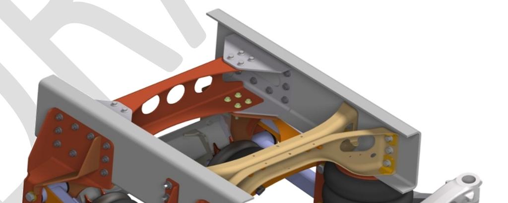
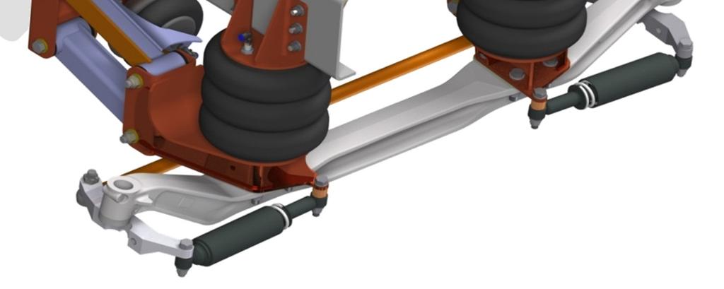
4 3. SUSPENSION PARTS DESCRIPTION: SELF STEERABLE LIFT AXLE 6T TAG Fig-1 PART LIST S.no Part MTBL Part Number Number DESCRIPTION QTY EAP00860N LBA - LH EAP00870N LBA - RH EAP00880N HANGER-LH EAP00890N HANGER-RH EAP00820N H-H CROSS CHANNEL ASSY FAP00030N UPPER CONTROL ARM ASSY LH FAP00040N UPPER CONTROL ARM ASSY RH FAP00050N LOWER CONTROL ARM ASSY DAP00170N UPPER ASPG MTG ASSY CAP00010N LOAD SPRING CAP00020N LIFT SPRING GAP00010N STEER DAMPER BAP00030N EXT.MALE-ELBOW M12X1.5- Ø BAP00040N MALE-ELBOW 1/4" NPT - Ø EAP00900N WEAR WASHER 16 Page 15
 and M18-1.50 X 110 HHCS (Item #3).Refer below part list.(as shown in the fig-1.1). Fig-1.1 PART LIST S.")
5 4. DISMANTLING PROCEDURE: While doing Servicing of Lift axle it is safe to depressurize the Air bellows (Load spring and Lift spring) STEER DAMPER: Steer Damper can be removed by loosening the M X 120 HHCS (Item #2) and M X 110 HHCS (Item #3).Refer below part list.(as shown in the fig-1.1). Fig-1.1 PART LIST S.NO PART NUMBER MBTL PART NUMBER DESCRIPTION QTY GRADE GAP00010N STEER DAMPER EAP01040N M X 120 HHCS 2 GRADE EAP01050N M X 110 HHCS 2 GRADE EAP01060N M HEX NUT 4 CLASS EAP01070N M18 - WASHER FLAT LOAD SPRING: Before removing / inspecting air spring it is safe to depressurize the Air bellows (Load spring and Lift spring). Remove the Pneumatic fitting MALE-ELBOW 1/4" NPT - Ø12 (item #2) from the combo stud. The main spring can be removed by loosening 3/8" - 16NC 1" LG HHCS (item #3), 1/2" - 13NC NYLON INSERT (item #5) and 3/4" - 16NF NYLON INSERT (item #6). (As show in the fig-1.2 & 1.3) Page 16


. Remove the Pneumatic fitting MALE-ELBOW M12X1.")
6 Fig-1.2 fig-1.3 PART LIST S.NO PART MBTL PART NUMBER NUMBER DESCRIPTION QTY GRADE CAP00010N AIR SPRING-CONTITECH BAP00040N MALE-ELBOW 1/4" NPT - Ø EAP00910N 3/8" - 16NC 1"LG HHCS 4 GRADE EAP00920N 3/8" - SPLIT LOCK WASHER EAP00980N 1/2" - 13NC NYLON INSERT 2 CLASS EAP01080N 3/4" - 16NF NYLON INSERT 2 CLASS LIFT SPRING: Before removing / inspecting air spring it is safe to depressurize the Air bellows (Load spring and Lift spring). Remove the Pneumatic fitting MALE-ELBOW M12X1.5- Ø12 (Item #2) from the combo stud. The Lift spring can be removed by loosening M X 20 HHCS (Item #3) and M NYLON INSERT (Item #5). (As show in the fig-1.4 & 1.5) Fig-1.4 fig-1.5 Page 17


7 PART LIST S.NO PART MBTL PART NUMBER NUMBER DESCRIPTION QTY GRADE CAP00020N AIR SPRING-FIRE STONE BAP00030N EXTENDED MALE-ELBOW M12X1.5- Ø EAP00930N M X 20 HHCS 4 GRADE EAP00940N M10 - WASHER INTERNAL TOOTH LOCK EAP01110N M NYLON INSERT 2 CLASS CONTROL ARM: Control Arms (item #1, #2 and #3) can be removed by loosening M X 190 HHCS bolt (item #5). (As show in the fig-1.6) Fig-1.6 PART LIST S.NO PART MBTL PART NUMBER NUMBER DESCRIPTION QTY GRADE FAP00030N UPPER CONTROL ARM ASSY LH FAP00040N UPPER CONTROL ARM ASSY RH FAP00050N LOWER CONTROL ARM ASSY EAP00900N WEAR WASHER EAP01130N M X 190 HHCS 8 GRADE EAP01140N M NYLON INSERT 8 CLASS EAP01150N M22 - WASHER FLAT 16 - Page 18


8 4.5 LOWER BEAM ASSY LH & RH: Lower Beam assembly can be removed from axle by loosening the M X 90 HHCS as shown in below fig-1.7 Fig-1.7 PART LIST S.NO PART NUMBER MBTL PART NUMBER DESCRIPTION QTY GRADE EAP00860N LBA - LH EAP00870N LBA - RH EAP01090N M X 90 HHCS 8 GRADE EAP01100N M HEX NUT 8 CLASS EAP01120N M20 - WASHER FLAT HANGER TO HANGER CROSS CHANNEL: Hanger to Hanger cross channel assembly can be removed from Hanger assembly LH and RH by loosening the M X 35 HFS as shown in below fig-1.8. Page 19 Fig-1.8


9 PART LIST S.NO PART MBTL PART NUMBER NUMBER DESCRIPTION QTY GRADE EAP00820N H-H CROSS CHANNEL ASSY EAP00950N M X 35 HFS 10 GRADE EAP00970N M HFN 10 CLASS HANGER ASSEMBLY LH & RH: Hanger assembly LH and RH can be removed from frame assembly by loosening the M X 45 HFS and M X 60 HFS as shown in below fig-1.9 Fig-1.9 PART LIST S.NO PART NUMBER MBTL PART NUMBER DESCRIPTION QTY GRADE EAP00880N HANGER-LH EAP00890N HANGER-RH EAP00960N M X 60 HFS 8 GRADE EAP00970N M HFN 8 CLASS EAP00990N M X 45 HFS 20 GRADE EAP01000N M HFN 20 CLASS UPPER AIR SPRING MTG BRKT ASSY: The Upper Air Spring Mtg Brkt assembly can be removed from frame assembly by loosening the M X 50 HFS and M X 55 HFS as shown in below fig-1.10 Page 20
10 Fig-1.10 PART LIST S.NO PART MBTL PART NUMBER NUMBER DESCRIPTION QTY GRADE DAP00170N UPPER ASPG MTG ASSY EAP01010N M X 50 HFS 4 GRADE EAP01020N M X 55 HFS 8 GRADE EAP01030N M HFN 12 CLASS-10 INSTALLATION PROCEDURE: 5.1. INSTALLATION OF HANGER ASSEMBLY AND HANGER CROSSMEMBERASSEMBLY Page 21 Fig-1.11


11 PART LIST S.NO PART NUMBER MBTL PART NUMBER DESCRIPTION QTY EAP00880N HANGER ASSY -LH EAP00890N HANGER ASSY -RH EAP00820N H-H CROSS CHANNEL ASSY EAP00950N M X 35 HFS EAP00970N M12 X 1.5 HF NUT CROSSMEMBER CHANNEL CROSSMEMBER MTG CHANNEL EAP00990N M X 45 HFS EAP00960N M12 X 1.5 X 60 HFS EAP01000N M14 X 1.5 HF NUT 20 TORQUE RECOMMENDATION SIZE TORQUE ft-lbs Nm M12 X M14 X Hanger assy. LH/RH will be in assembled condition. These were connected by H-H Cross Channel (as shown in fig 1.11) using M14 X (Note that it should not be tighten for adjustment purpose) PROCEDURE: Fig Locate Item no. 1, 2, & 7 in frame as shown in the figure using M14 x bolts. (Note that M14 x 1.5 bolts should not be tightened). 2. Place Item no.6 (CROSS MEMBER CHANNEL) in Item no.7 (CROSS MEMBER MTG CHANNEL) using M12 x HFS at Top & M12 x HFS at Bottom as shown in the figure.1.12 Tighten the M12 x 1.5 bolts loosely. 3. Once located everything, torque should be applied for all bolts as per chart. Page 22


12 5.2. INSTALLATION OF LIFT SPRING WITH H H CROSS CHANNEL ASSEMBLY Fig-1.13 Fig1.14 PART LIST S.NO PART NUMBER MBTL PART NUMBER DESCRIPTION QTY EAP00880N HANGER ASSY -LH EAP00890N HANGER ASSY -RH EAP00820N H-H CROSS CHANNEL ASSY CAP00020N LIFT SPRING EAP00930N M X 20 HHCS EAP00940N M10 INTERNAL TOOTHLOCK WASHER 4 TORQUE RECOMMENDATION TORQUE SIZE ft-lbs Nm M10 X PROCEDURE: Place the Item no.4 (LIFT SPRING) in Item no.3 (H-H Cross Channel Assy.) as shown in fig-1.13, 1.14 using M10 X 1.5 bolt. (Note that the over tightening of M10 X 1.5 cause air spring failure) INSTALLATION OF UPPER AIR SPRING BRACKET ASSY AND CROSSMEMBER ASSEMBLY Page 23
13 Fig-1.15 PART LIST S.NO PART NUMBER MBTL PART NUMBER DESCRIPTION QTY DAP00170N UPPER A/SPG BRACKET ASS'Y EAP01010N M16 X 1.5 X 50 HFS EAP01020N M16 X 1.5 X 55 HFS EAP01030N M16 X 1.5 HF NUT 12 TORQUE RECOMMENDATION TORQUE SIZE ft-lbs Nm M16 X PROCEDURE: 1. Locate Item no.1 in frame as shown in the figure using M16 x 1.5 bolts (Item no. 2 & 3). 2. Finally tighten the M16 x 1.5 as per above torque chart INSTALLATION OF LOWER BEAM ASSEMBLY AND STEER DAMPERS Page 24
14 Fig-1.16 PART LIST S.NO PART NUMBER MBTLPART NUMBER DESCRIPTION QTY EAP00860N LOWER BEAM ASSY LH EAP00870N LOWER BEAM ASSY RH EAP01090N M X 90 HHCS EAP01100N M HEX NUT EAP01120N M20 WASHER FLAT GAP00010N STEER DAMPER TIE ROD ARM LH TIE ROD ARM RH EAP01040N M18 X 1.5 x 120 HHCS EAP01050N M18 X 1.5 x 110 HHCS EAP01060N M18 X 1.5 NYLON INSERT EAP01070N M18 WASHER FLAT 8 TORQUE RECOMMENDATION SIZE TORQUE ft-lbs Nm M18 X M20 X Turn the LH/RH tire outside to match the uncompressed length of steer damper. 2. Once the required dimension is achieved, the damper end holes has to be matched & bolted with the LBA hole & tie rod arm hole. 3. Torque the fasteners to the specification mentioned in drawing. 4. After fitting the steer damper on LH/RH side, other side tyre has to be turned outside in the same way followed in 1 st step. 5. There will be more force required to turn the tire due to stiffness of steer damper already fitted on one side. Page 25


15 6. For Ease in turning the tire, one can use long rod or lever for better leverage. The same procedure followed in 1 st step has to be repeated here. PROCEDURE: 1. Locate item no. 1 & 2 in Axle using LBA dowel pin. Bolt it by using M20 X HHCS loosely. 2. Using M x 110 HHCS bolt place one end of Steer Damper (item no. - 6) in Tie Rod Arm and other end to the Lower Beam assembly (item no. 1 and 2) by using M x 120 HHCS bolt. 3. Once located everything, torque should be applied for all bolts as per chart INSTALLATION OF CONTROL ARMS Fig-1.17 PART LIST S.NO PART NUMBER MBTLPART NUMBER DESCRIPTION QTY EAP00880N HANGER ASSY -LH EAP00890N HANGER ASSY -RH FAP00030N UPPER CONTROL ARM ASS'Y LH FAP00040N UPPER CONTROL ARM ASS'Y RH FAP00050N LOWER CONTROL ARM ASS'Y EAP01130N M22 X 1.5 X 190 HHCS EAP01140N M22 X 1.5 NYLON INSERT EAP01150N M22 WASHER FLAT CAP00020N LIFT SPRING EAP01110N M NYLON INSERT EAP00860N LOWER BEAM ASS'Y - LH EAP00870N LOWER BEAM ASS'Y -RH EAP00900N WEAR WASHER 16 Page 26
 in item no. - 1 & 2 (HNAGER ASSY LH/RH) by using M22 X 1.5 bolt (as shown in fig-1.17). Tighten the bolt loosely. 2. Insert Air spring Combo stud of item no.")
16 TORQUE RECOMMENDATION SIZE TORQUE ft-lbs Nm M20 X 1.5 NI NUT M22 X PROCEDURE: 1. Locate item no. 3, 4, & 5 (UPPER CONTROL ARM ASSY LH/RH and LOWER CONTROL ARM ASSY) in item no. - 1 & 2 (HNAGER ASSY LH/RH) by using M22 X 1.5 bolt (as shown in fig-1.17). Tighten the bolt loosely. 2. Insert Air spring Combo stud of item no.10 into item no 3 and 4 (UPPER CONTROL ARM ASSY LH/RH as shown in fig-1.17). Tighten the air spring Combo stud using M20 X 1.5 NYLON INSERT as per above torque chart. (Note that the over tightening of M20 X 1.5 NYLON INSERT cause air spring failure). 3. Fix item no. 11 & 12 (LOWER BEAM ASSY'S LH/RH) to the item no. 3, 4 & 5 (UPPER CONTROL ARM ASSY LH/RH and LOWER CONTROL ARM ASSY) using M22 X 1.5 bolt (as shown in fig- 1.18). Fig Check whether the axle is perpendicular to frame. Measure the distance between left end of the axle and any fixed reference (Drive axle or non-steerable dead axle which are perpendicular to frame) (as shown in fig-5.3). Similarly measure the distance for right end of axle. Page 27 Fig-1.19
 as per above torque chart. 7. The tag lift axle should be parallel to Rear axle RA1/RA2.")
17 5. Adjust the lift axle position (by adjusting the CONTROL ARM ASSY (item no. 3, 4, 5), Lower Beam Assy LH/RH (item no. 11 &12) & HANGER ASSY LH/RH (item no. 1, 2). So that A equal to B. 6. Finally tighten the M22 X 1.5 bolt & M20 X 1.5(Axle Bolts) as per above torque chart. 7. The tag lift axle should be parallel to Rear axle RA1/RA2. To ensure the parallelism & correct location of tag lift axle, (a) The distance (A & B) of (LA) axle center from any fixed reference should be equal on both LH & RH side. The fixed reference can be RA1 or RA2. (b) The distances should be measured on vehicle parked on level surface. (c) Ensure that vehicle is in straight ahead condition prior to measurements. (d) Fine adjustments may be required on LBA, Control arms & hanger to get the distances (A & B) equal on both the sides. (e) The lift axle should be correctly located with respect to Rear axle as per specification. Incorrectly located lift axle results in incorrect load distribution on axles INSTALLATION OF LOAD SPRING Fig-1.2 Fig-1.21 PART LIST S.NO PART NUMBER MBTL PART NUMBER DESCRIPTION QTY DAP00170N UPPER A/SPG BRACKET ASS'Y CAP00010N LOAD SPRING EAP00910N 3/8-16NC X 1"L HHCS EAP00920N 3/8-WASHER SPLIT LOCK EAP00980N 1/2-13NC NYLON INSERT EAP01080N 3/4-16NF NYLON INSERT 2 Page 28 TORQUE RECOMMENDATION SIZE TORQUE ft-lbs Nm 3/ / /
18 PROCEDURE: Place item no. 2 (LOAD SPRING) in between LOWER BEAM ASSEMBLY and A/SPG BRACKET ASSY- UPPER (item no.3 & 4). Use above listed fasteners to fix Air spring. The fasteners to be tightened as per above torque chart. (Note that the over tightening of air spring fasteners cause air spring failure). Bushing Replacement & Re-assembly Procedure First chock the wheels and secure the vehicle. Lift the Liftable axle and block up the axle, remove the wheels and deflate the air springs. Dismantle the Main air spring & lift air spring. Dismantle the Control arm s M22 nuts and bolts from LBA Side and then hanger side. And then dismantle the control arms from the Assembly s. Inspect Hanger assembly & LBA Assembly holes and mating surfaces for unusual wear or damage. Repair or replace components as required. Remove the damaged PU bushing and inner metal bushing sleeve from the control arm eye by using press M/C. Clean the bushing eye of corrosion and debris. Apply the soap solution to the new bushing outer diameter surface and inner diameter surface of control arm eye for ease installation. Place the new PU bushing over the control arm eye and then press the PU bushing into the control arm sleeve by using press M/C. And then press the metal bushing sleeve into the PU bushing. During pressing, make sure that PU bushing & Metal bushing sleeve are equally placed in the control arm s eye. After Pressing, Please ensure the dimension as shown in the figure Install the new wear washers on both sides of the new bushing and then assemble into the hanger & LBA assembly with new M22X1.5X190mm bolt, M22X1.5 Cleve Lock nut & M22 Washer. And then tighten the M22 Bolt & nut to the torque (780Nm-840Nm). Reassemble the suspension in reverse order from above. (a) The replacement dimension for wear washer is its thickness. (b) The deformation for wear washer is generally non uniform & observed deformation patterns in field are cup shaped. The thickness of washer is 6.35 mm. It has to be replace when the measured thickness is less than 3 mm or washer found to be teared from any direction. (c) The PU bushes are press fitted within control arm sleeves & it is not possible to check its dimensions without its complete removal. (d) However while replacing the wear washer one should check thoroughly the bushings for its physical conditions. It has to be replaced if found teared from any direction.. Fig-1.22 Page 29
19 10. SPECIAL TOOL REQUIREMENT FOR SERVICING 1. M22 Bolt Ring Spanner. (Control arm Fasteners). 2. M22 Bolt Box socket. (Control arm Fasteners). 3. Standard tools 6. AFTER ASSEMBLY INSPECTION 1. In lifted condition Static height should be mm & in Rebound 451.5mm 2. Reduce the air pressure to the load springs to below 10 psi. Operate the suspension up and down to ensure proper operation and suspension clearance to other components. Check that the driveline has adequate clearance when the suspension is lifted. 3. Check that all fasteners are tightened to the proper torque values. Page 30
20 8. SERVICABLE PART LIST S.n o Part Number MTBL Part Number DESCRIPTION QTY LH/RH EAP00860N LBA - LH 1 LH ASSY EAP00870N LBA - RH 1 RH ASSY EAP00880N HANGER-LH 1 LH ASSY EAP00890N HANGER-RH 1 RH ASSY EAP00820N H-H CROSS CHANNEL ASSY 1 ASSY FAP00030N UPPER CONTROL ARM ASSY LH 1 LH ASSY FAP00040N UPPER CONTROL ARM ASSY RH 1 RH ASSY FAP00050N LOWER CONTROL ARM ASSY 2 ASSY DAP00170N UPPER ASPG MTG ASSY 2 ASSY BAP00050N STANDARD PARTS CAP00010N LOAD SPRING 2 STD Part CAP00020N LIFT SPRING 2 STD Part GAP00010N STEER DAMPER 2 STD Part BAP00030N EXT.MALE-ELBOW M12X1.5- Ø12 2 STD Part BAP00040N MALE-ELBOW 1/4" NPT - Ø12 2 STD Part EAP00900N WEAR WASHER 16 STD Part FAP00090N BUSHING-URETHANE 8 STD Part FAP00100N BUSHING-SLEEVE 8 STD Part EAP00830N FASTENER KIT EAP00910N 3/8" - 16NC 1"LG HHCS 4 STD Part EAP00920N 3/8" - WASHER SPLIT LOCK 4 STD Part EAP00930N M X 20 HHCS 4 STD Part EAP00940N M10 - WASHER INTERNAL TOOTH 4 STD Part EAP00950N M X 35 HFS 18 STD Part EAP00960N M X 60 HFS 8 STD Part EAP00970N M HFN 26 STD Part EAP00980N 1/2" - 13NC NYLON INSERT 2 STD Part EAP00990N M X 45 HFS 20 STD Part EAP01000N M HFN 20 STD Part EAP01010N M16-1.5X50 HFS 4 STD Part EAP01020N M16-1.5X55 HFS 8 STD Part EAP01030N M16-HFN 12 STD Part EAP01040N M X 120 HHCS 2 STD Part EAP01050N M X 110 HHCS 2 STD Part EAP01060N M NYLON INSERT 4 STD Part EAP01070N M18-WASHER FLAT 8 STD Part EAP01080N 3/4" - 16NF NYLON INSERT 2 STD Part EAP01090N M X 90 HHCS 8 STD Part EAP01100N M HEX NUT 8 STD Part EAP01110N M20- NYLON LOCK INSERT NUT 2 STD Part EAP01120N M20- WASHER FLAT 16 STD Part EAP01130N M X 190 HHCS 8 STD Part EAP01140N M NYLON INSERTS 8 STD Part EAP01150N M22- WASHER FLAT 16 STD Part Page 31
21 8. MAINTENANCE SCHEDULE Sr No Nature of work Frequency (Km) 1 Hub greasing for tag axle with replacement of oil seal, Adjust hub play Check for excessive king pin play,stub axle play adjust if required Check for excessive wear of king pin bush replace if required Check condition of brake drum & brake liner replace if required Wheel alignment on electronic wheel aligner Load sensing valve link rod adjustment Replace the kit of actuation valve like PLV,GRV, load sensing valve Once in a 2 years 8 Check & tighten the all hardware of the lift axle structural members Daily 9 10 Check for any fouling or intersecting of components in lift as well as in nonlift condition Check condition of steering dampers, rubber mountings, oil leakage replace if required Daily Check condition of lift bellow Check condition of load bellow Check for any air leakage in actuation system Daily 14 Check for any leakage in bellows Daily 15 Check for any welding breakage in structural members Daily 16 Check wear washers condition for the wear, replace if required Check condition of rubber bushing for wear, replace if required Check & tighten the all hardware of the lift axle structural members after first trip & then every km Check tyre pressure Daily 20 Tyre rotation Check lift axle operation before the trip Daily 22 Check operational switch fitted in cabin or cowl Daily Page 32
22 9. PREVENTIVE MAINTENANCE DAILY Check for loose or broken parts on or around suspension to prevent any serious problems from occurring. EVERY 30 DAYS Check clearances around all moving suspension parts, air springs, tires and shock absorbers. Any signs of interference should be immediately corrected. Visually inspect axle beam bolted connection to make sure bolts are tight and there are no signs of wear. EVERY 90 DAYS & WITH ANNUAL INSPECTION Inspect items required in daily and 30-day inspections. Inspect all welded connections Inspect all pivot and clamping connections such as the suspension pivots and shock mounts. Trouble shooting - Sr no Failure Reason Remedy Not getting desired load Improper air pressure to load air spring Inflate with correct air pressure 1 on the axle suspension mounted improperly Check for the correct mounting 2 In sufficient air pressure in the system 3 Not getting correct lift 4 Axle shimmy 5 Tyre wear Defective air compressor- air inflation in the system Leakage in layout circuit Lift air bags not getting proper air pressure Load sensing valve setting defective Layout circuit defective Toe setting is incorrect Pivot bolt loose Tyre uneven wear Leakage in steer damper King pin shims excessive play Toe setting is incorrect steer damper setting incorrect Steer damper bush weared off Excessive wear in wear washers & bushings of control arm Insufficient tyre pressure Loose control arm hardware Excessive play in king pin shims & bushes Lift axle lifted in partial condition Check air compressor for building the air pressure Check leakage & rectify Check the actuation circuit & rectify Adjust to 105 mm Rectify Correct with 1-3 mm toe in setting / for lift axle adjust -1.5 to mm (toe out) Tightened the loose bolt Check for tyre wear & rectify Replace the steering damper Rectify Adjust Adjust Replace the steering damper Replace Correct Rectify Rectify Rectify Page 33
23 Actuation system Actuation system Knorr Bremse Circuit diagram - Lift axle load sensing mechanism Load sensing valve is supplied by Wabcco is fitted in between rear tandem axle. Page 34
24 The link rod position in unladen condition will be horizontal as shown in fig below. In laden condition it will be angular with approximate angle of 24 degree. Page 35

 Toe value for rear tag")
25 In case we require to adjust the length of load sensing mechanism it is as per below dimension. 105 mm +2 /-1 mm Wheel Alignment Carry out the wheel alignment at every km on electronic wheel aligner with tyre rotation as per below. Toe value for front 2 axle 1 to 3 mm (Set toe in value viewing from vehicle front) Toe value for rear tag lift axle is -1.5 to mm (Set toe out value viewing from vehicle front) Page 36
26 For electronic wheel alignment data Camber angle Caster angle Toe value Parallelism ( Applicable to Truxo31& 37) Scrub angle ( Axle skewness value) Thrust angle ( Axle perpendicularity with Chassis) Toe value for tag lift axle for Truxo to degree 3 to 4 degree 1 to 3 mm +/- 5 minute +/- 5 minute +/- 5 minute -1.5 to -3.5 mm (toe out) 12. DO S and DON T S in lift axle: DO s: 1. Ensure that Lift axle automatically lifted when truck is travelling in reverse condition. 2. Lift the lift axle in traction loose condition with manual override switch. 3. Always check state laws in all states through which you will be traveling for legal allowable weight and axle configuration. 4. Check lift axle fasteners torque as per specification before delivery of vehicle to customer. 5. Ensure that Max cut screw setting on LA as per specs. 6. When performing maintenance on LA, ensure that air is not supplied to the air springs. Component damage, bodily injury can otherwise result. 7. When operating your lift axle, ensure that all personnel are at safe distance from the actuating lift axle. 8. Be careful during suspension operation as suspension components move at a rapid rate. 9. Regularly check for Critical fasteners Torque's as per spec. DON T: 1. Don t lift the lift axle in laden condition. 2. Don t temper front / rear suspension. 3. Don t tamper pneumatic components such as Pressure Control Valve, Load Sensing Valve linkage. Page 37
27 4. Suspensions are designed to operate within specific parameters. Operating the suspension outside the design parameters may result in improper performance, damaged equipment, and void of warranty. 5. Don't over torque Air spring assy. mountings this will lead to failure of air springs. 6. Don't over torque steer damper mountings this will lead to crushing of shock inner sleeves Page 38
RSS Truck Suspension Self-Steer Air-Ride Suspension System for Customer-Supplied I-Beam Axle
 RSS-2361000-Truck Suspension Self-Steer Air-Ride Suspension System for Customer-Supplied I-Beam Axle Installation and Service Manual Suspension Identification... 2 Suspension System Serial Tag Prior to
RSS K Truck Self-Steering Air-Ride Suspension
 RSS-233-20K Truck Self-Steering Air-Ride Suspension Installation and Service Manual Suspension Identification... 2 Suspension System Serial Tag Installation... 3 Prior to Installation Suspension Mounting
RSS K Truck Self-Steering Auxiliary Axle Suspension
 RSS-233-10K Truck Self-Steering Auxiliary Axle Suspension Installation and Service Manual Suspension Identification... 2 Suspension System Serial Tag Installation... 3 Torque Specifications Prior to Installation
RSS-232/232T 20K Truck and Trailer Self-Steering Auxiliary Axle Suspension
 RSS-232/232T 20K Truck and Trailer Self-Steering Auxiliary Axle Suspension RSS-232 - Truck suspension shown Installation and Service Manual Suspension Identification... 2 Suspension System Serial Tag Installation...
RSS-233T - 13K Trailer Self-Steering Air-Ride Suspension
 RSS-233T - 13K Trailer Self-Steering Air-Ride Suspension Installation and Service Manual Suspension Identification... 2 Suspension System Serial Tag Installation... 3 Torque Specifications Prior to Installation
RSS-233T - 20K Trailer Self-Steering Air-Ride Suspension
 RSS-233T - 20K Trailer Self-Steering Air-Ride Suspension Installation and Service Manual Suspension Identification... 2 Suspension System Serial Tag Installation... 3 Prior to Installation Suspension Mounting
RSS-232/232T - 8K-10K-13K Self-Steering Auxiliary Axle Suspension
 RSS-232/232T - 8K-10K-13K Self-Steering Auxiliary Axle Suspension Installation and Service Manual Suspension Identification... 2 Suspension System Serial Tag Installation... 3 Prior to Installation Suspension
OWNER S GUIDE 8A DURALIFT II 13,200 LB. CAPACITY. Link Mfg. Ltd th St. N.E. Sioux Center, IA USA
 OWNER S GUIDE 8A000715 DURALIFT II 13,200 LB. CAPACITY Link Mfg. Ltd. 223 15th St. N.E. Sioux Center, IA USA 51250-2120 www.linkmfg.com QUESTIONS? CALL CUSTOMER SERVICE 1-800-222-6283 DEALER / INSTALLER:
RSS-233T - 13K Trailer Self-Steering Air-Ride Suspension
 RSS-233T - 13K Trailer Self-Steering Air-Ride Suspension Installation and Service Manual Suspension Identification... 2 Suspension System Serial Tag Installation... 3 Torque Specifications Prior to Installation
RSS K Truck Self-Steering Auxiliary Axle Suspension
 RSS-233-13K Truck Self-Steering Auxiliary Axle Suspension Installation and Service Manual Suspension Identification... 2 Suspension System Serial Tag Installation... 3 Torque Specifications Prior to Installation
RD-202S. Heavy-Duty Tandem Drive Truck Suspension Owner s Manual
 RD-202S Heavy-Duty Tandem Drive Truck Suspension Owner s Manual www.ridewellcorp.com P.O. Box 4586 Springfield, MO 65808 47.833.4565 47.833.4560 (fax) 073 Suspension Identification: Ridewell Suspensions
Kits (with shocks), (no shocks) Audi B9
, (no shocks) Audi B9") Kits 78670 (with shocks), 78671 (no shocks) Audi B9 Rear Application MN-1074 (011808) ERN 8788 INSTALLATION GUIDE For maximum effectiveness and safety, please read these instructions completely before
Kits 78670 (with shocks), 78671 (no shocks) Audi B9 Rear Application MN-1074 (011808) ERN 8788 INSTALLATION GUIDE For maximum effectiveness and safety, please read these instructions completely before
MS2200, MS2500, and MS3000 Suspension Installation Manual ON/OFF HIGHWAY SUSPENSION SYSTEM
 MS22, MS25, and MS3 Suspension Installation Manual ON/OFF HIGHWAY SUSPENSION SYSTEM 972.547.62 8.445.736 FAX: 972.542.97 725 E. UNIVERSITY ST. McKINNEY, TEXAS 7569 www.watsonsuspensions.com Watson & Chalin
INSTALLATION INSTRUCTIONS
 INSTALLATION INSTRUCTIONS GMT 560 (4500/5500) CREW CAB (2351A000) Link Mfg. Ltd. 223 15th St. N.E. Sioux Center, IA USA 51250-2120 The CABMATE MODEL 2351A000 fits the 2003 and later GM 4500 / 5500 crew
SUSPENSION 2-1 SUSPENSION TABLE OF CONTENTS
 XJ SUSPENSION 2-1 SUSPENSION TABLE OF CONTENTS page ALIGNMENT... 1 FRONT SUSPENSION... 7 page REAR SUSPENSION... 16 ALIGNMENT TABLE OF CONTENTS page AND WHEEL ALIGNMENT...1 DIAGNOSIS AND TESTING SUSPENSION
Return To Main Table of Contents GENERAL... 2 STRUT ASSEMBLY LOWER ARM STABILIZER BAR CENTER MEMBER WHEEL AND TIRE...
 FRONT SUSPENSION Return To Main Table of Contents GENERAL... 2 STRUT ASSEMBLY... 11 LOWER ARM... 13 STABILIZER BAR... 17 CENTER MEMBER... 19 WHEEL AND TIRE... 21 GENERAL GENERAL SPECIFICATIONS Suspension
1. SPECIFICATIONS 2. WHEEL ALIGNMENT Front Suspension. (gas type) Rear Suspension. (gas type)
 Rear Suspension. (gas type)") 441101 053 1. SPECIFICATIONS Front Suspension Rear Suspension Description Suspension type Spring type Shock absorber type Stabilizer bar type Suspension type Spring type Shock absorber type Stabilizer
441101 053 1. SPECIFICATIONS Front Suspension Rear Suspension Description Suspension type Spring type Shock absorber type Stabilizer bar type Suspension type Spring type Shock absorber type Stabilizer
Refer to separate Installation Instructions for installation details.
 OWNER S GUIDE 8A000729 DuraLift 13.5 13,500 CAPACITY Link Mfg. Ltd. 223 15th St. N.E. Sioux Center, IA USA 51250-2120 www.linkmfg.com QUESTIONS? CALL CUSTOMER SERVICE 1-800-222-6283 DEALER / INSTALLER:
Air Ride Single Point Suspension. Installation and Service Manual
 RAR-254 Air Ride Single Point Suspension Installation and Service Manual Suspension Identification... 2 Suspension System/Axle Serial Tag Installation... 3 Prior to Installation Suspension Mounting Troubleshooting
OWNERS MANUAL. GMC C K AND 19K GVW CHASSIS CAB 2004-NEWER MODELS (Link Part No. 8M000050) PROUDLY INSTALLED BY : COMPANY : INSTALLER SIGNATURE :
 PROUDLY INSTALLED BY : COMPANY : INSTALLER SIGNATURE :") OWNERS MANUAL GMC C5500 15K AND 19K GVW CHASSIS CAB 2004-NEWER MODELS (Link Part No. 8M000050) Link Mfg. Ltd. 223 15th St. N.E. Sioux Center, IA USA 51250-2120 (712) 722-4868 Fax (712) 722-4779 QUESTIONS?
OWNERS MANUAL GMC C5500 15K AND 19K GVW CHASSIS CAB 2004-NEWER MODELS (Link Part No. 8M000050) Link Mfg. Ltd. 223 15th St. N.E. Sioux Center, IA USA 51250-2120 (712) 722-4868 Fax (712) 722-4779 QUESTIONS?
TECHNICAL PROCEDURE NON-STEERABLE SUSPENSION SYSTEMS
 TECHNICAL PROCEDURE NON-STEERABLE SUSPENSION SYSTEMS SUBJECT: Installation Instructions LIT NO: DATE: December 2003 TABLE OF CONTENTS Introduction... 2 Required Supplies... 2 Pre-Installation Checklist...
FRONT SUSPENSION SECTION FSU CONTENTS E SUSPENSION FSU-1 FSU
 E SUSPENSION SECTION FSU A FRONT SUSPENSION B C D CONTENTS FSU PRECAUTIONS... 2 Precautions... 2 PREPARATION... 3 Special Service Tools... 3 Commercial Service Tools... 3 NOISE, VIBRATION, AND HARSHNESS
Airflex Air Ride Suspension System Installation Instructions
 www.dexteraxle.com Airflex Air Ride Suspension System Installation Instructions Frame Styles Tube Frame Outside Frame Dimension Outside Bracket Dimension Channel Frame Outside Frame Dimension "C" Channel
INSTALLATION INSTRUCTIONS
 INSTALLATION INSTRUCTIONS 8A000729 DuraLift 13.5 13,500 LB. CAPACITY Link Mfg. Ltd. 223 15th St. N.E. Sioux Center, IA USA 51250-2120 www.linkmfg.com QUESTIONS? CALL CUSTOMER SERVICE 1-800-222-6283 Refer
OWNERS MANUAL GM C4500/C5500 DANA MODEL S135 REAR AXLE 2003-NEWER MODELS LINK MFG. PART NO. 8M PROUDLY INSTALLED BY : COMPANY :
 OWNERS MANUAL GM C4500/C5500 DANA MODEL S135 REAR AXLE 2003-NEWER MODELS LINK MFG. PART NO. 8M000030 Link Mfg. Ltd. 223 15th St. N.E. Sioux Center, IA USA 51250-2120 (712) 722-4874 Fax (712) 722-4876 QUESTIONS?
FRONT SUSPENSION SECTION CONTENTS E SUSPENSION FSU-1 FSU
 E SUSPENSION A SECTION FRONT SUSPENSION B C D CONTENTS FSU PRECAUTIONS... 2 Precautions... 2 PREPARATION... 3 Special Service Tools... 3 Commercial Service Tools... 3 NOISE, VIBRATION, AND HARSHNESS (NVH)
1. SPECIFICATIONS 2. WHEEL ALIGNMENT
 441101 083 1. SPECIFICATIONS Front Suspension Rear Suspension Description Suspension type Spring type Shock absorber type Stabilizer bar type Suspension type Spring type Shock absorber type Stabilizer
Airflex Air Ride Suspension System Installation Instructions
 Airflex Air Ride Suspension System Installation Instructions Frame Styles Tube Frame Outside Frame Dimension Outside Bracket Dimension Channel Frame Outside Frame Dimension "C" Channel frames should be
REAR SUSPENSION GROUP CONTENTS GENERAL DESCRIPTION REAR SUSPENSION DIAGNOSIS LOWER ARM AND TOE CONTROL ARM ASSEMBLY...
 34-1 GROUP 34 CONTENTS GENERAL DESCRIPTION........... 34-2 DIAGNOSIS.... 34-2 INTRODUCTION....................... 34-2 TROUBLESHOOTING STRATEGY........ 34-2 SYMPTOM CHART..................... 34-3 SYMPTOM
KI AIR SUSPENSION (wide Pivot Bush)
") KI AIR SUSPENSION (wide Pivot Bush) Contents 1. Pre-assembly Considerations 2. Welding Instructions Chassis Connection 3. Tightening Instruction 4. Axle Alignment 5. Maintenance www.khitch.com.au Uncontrolled
KI AIR SUSPENSION (wide Pivot Bush) Contents 1. Pre-assembly Considerations 2. Welding Instructions Chassis Connection 3. Tightening Instruction 4. Axle Alignment 5. Maintenance www.khitch.com.au Uncontrolled
REAR SUSPENSION GROUP CONTENTS GENERAL DESCRIPTION TRAILING ARM REAR SUSPENSION DIAGNOSIS TOE CONTROL ARM...
 34-1 GROUP 34 CONTENTS GENERAL DESCRIPTION 34-2 DIAGNOSIS 34-3 INTRODUCTION TO DIAGNOSIS 34-3 DIAGNOSTIC TROUBLESHOOTING STRATEGY 34-3 SYMPTOM CHART 34-3 SYMPTOM PROCEDURES 34-3 SPECIAL TOOLS 34-5 ON-VEHICLE
DIAGNOSIS AND TESTING
 DIAGNOSIS AND TESTING SUSPENSION AND STEERING SYSTEM 2007 SUSPENSION Suspension - Nitro CONDITION POSSIBLE CAUSES CORRECTION FRONT END NOISE 1. Loose or worn wheel bearings. 1. Replace wheel bearings.
FRONT SUSPENSION GROUP 2 FRONT SUSPENSION 2-1 CONTENTS SPECIFICATIONS VC-1, VC-2, VC-3 VY-1 TOOL LIST. Page
 GROUP 2 FRONT SUSPENSION CONTENTS Page Specifications 1 Tool List.... 1 Torque Reference 2 Preparation for Measuring Front End Alignment... 2 Front Suspension Height Adjustment 3 Front Suspension Alignment
SUSPENSION SYSTEM PROBLEM SYMPTOMS TABLE SP 1
 SUENSION SUENSION SYSTEM 1 Vehicle/pulls Bottoming Sway/pitches Wheel shimmy Abnormal tire wear SUENSION SYSTEM PROBLEM SYMPTOMS TABLE Use the table below to help determine the cause of the problem. The
PERFORMANCE SUSPENSION PARTS
 PERFORMANCE SUSPENSION PARTS Introduction Air Lift Performance The purpose of this publication is to assist with the installation, maintenance and troubleshooting of this Chrysler LX, LD, LC Platform 300C,
SUSPENSION SYSTEM PROBLEM SYMPTOMS TABLE SP 1
 SUENSION SUENSION SYSTEM 1 SUENSION SYSTEM Suspension system Vehicle is unstable Bottoming Sways/pitches Wheels shimmy Abnormal tire wear Vehice pull PROBLEM SYMPTOMS TABLE Use the table below to help
INSTALLATION INSTRUCTION Rev A
 INSTALLATION INSTRUCTION 88587 Rev A FOR RANCHO SUSPENSION SYSTEM RS6587B: 2009 DODGE RAM 1500 READ ALL INSTRUCTIONS THOROUGHLY FROM START TO FINISH BEFORE BEGINNING INSTALLATION IMPORTANT NOTES! WARNING:
INSTALLATION AND MAINTENANCE MANUAL
 IMPORTANT This manual must accompany the trailer when delivered to the end user. INSTALLATION AND MAINTENANCE MANUAL ISS Series Suspensions 347 King Street West, Ingersoll, Ontario, Canada, N5C 3K6 Ph:
OWNERS MANUAL GM C4500/C5500 4X4 DANA MODEL S135 REAR AXLE 2005-NEWER MODELS LINK MFG. PART NO. 8M PROUDLY INSTALLED BY : COMPANY :
 OWNERS MANUAL GM C4500/C5500 4X4 DANA MODEL S135 REAR AXLE 2005-NEWER MODELS LINK MFG. PART NO. 8M000060 Link Mfg. Ltd. 223 15th St. N.E. Sioux Center, IA USA 51250-2120 (712) 722-4874 Fax (712) 722-4876
Air Lift. Kit Ford Mustang SN95 PERFORMANCE INSTALLATION GUIDE. Rear Application
 Air Lift PERFORMANCE Kit 78619 Ford Mustang SN95 Rear Application INSTALLATION GUIDE PERFORMANCE SUSPENSION PARTS For maximum effectiveness and safety, please read these instructions completely before
INDEX GENERAL. Page Connecting Rod 2M-3 Front Wheel Alignment 2M-4 Front Wheel Shimmy 2M-5 General 2M-1
 INDEX Page Connecting Rod 2M-3 Front Wheel Alignment 2M-4 Front Wheel Shimmy 2M-5 General 2M-1 Pago Specifications 21-8 Steering Damper 2M-3 Steering Wheel Spoke Alignment 2M-5 Tie Rod 2M-3 GENERAL The
ADL SERIES MAINTENANCE AND PARTS LIST. ADL Drive-Axle Air-Ride Suspension Maintenance and Parts List Manual XL-AK GO THE DISTANCE.
 GO THE DISTANCE. ADL SERIES MAINTENANCE AND PARTS LIST ADL-10-7 Drive-Axle Air-Ride Suspension Maintenance and Parts List Manual XL-AK400-01 1 CONTENTS Page Introduction...3 Warranty...3 Notes, Cautions,
INSTALLATION OF RAILGEAR KIT R-290HD REAR
 INSTALLATION OF RAILGEAR KIT R-290HD REAR Page 1 of 29 SAFETY PRECAUTIONS If any installation problems are encountered, please call G&B Specialties, Inc. for technical assistance before continuing with
FRONT SUSPENSION GROUP 33A 33A-1 CONTENTS GENERAL DESCRIPTION... 33A-2 FRONT SUSPENSION DIAGNOSIS. 33A-3 LOWER ARM... 33A-13 SPECIAL TOOLS...
 33A-1 GROUP 33A FRONT SUSPENSION CONTENTS GENERAL DESCRIPTION......... 33A-2 DIAGNOSIS. 33A-3 INTRODUCTION TO DIAGNOSIS........................ 33A-3 DIAGNOSIS TROUBLESHOOTING STRATEGY...... 33A-3 SYMPTOM
SAE STANDARD BOLT ASSEMBLY NUMBER 60020_IR4 INSTALLATION AND OPERATIONS MANUAL
 SAE STANDARD BOLT ASSEMBLY NUMBER 60020_IR4 INSTALLATION AND OPERATIONS MANUAL CONTENTS Important! Read Carefully... 1 Safety and Warnings... 2 Warning Rotating Equipment Hazard... 2 Warning Pinch Point
SUSPENSION 2-1 SUSPENSION CONTENTS
 WJ SUSPENSION 2-1 SUSPENSION CONTENTS page ALIGNMENT... 1 FRONT SUSPENSION... 4 page REAR SUSPENSION... 15 ALIGNMENT INDEX page AND WHEEL ALIGNMENT... 1 SERVICE PROCEDURES PRE-ALIGNMENT... 2 AND WHEEL
INSTALLATION INSTRUCTIONS 88518
 INSTALLATION INSTRUCTIONS 88518 For Rancho Suspension Systems RS6518: 2009 FORD F-150 4WD READ ALL INSTRUCTIONS THOROUGHLY FROM START TO FINISH BEFORE BEGINNING INSTALLATION Rev A IMPORTANT NOTES! WARNING:
INSTALLATION INSTRUCTIONS 88029
 INSTALLATION INSTRUCTIONS 88029 FOR SUSPENSION SYSTEMS RS6503: JEEP WRANGLER (TJ) READ ALL INSTRUCTIONS THOROUGHLY FROM START TO FINISH BEFORE BEGINNING INSTALLATION REV F IMPORTANT NOTES! WARNING: This
RideStar RHP Series Sliding Tandem Trailer Air Suspension System
 Maintenance Manual 14S RideStar RHP Series Sliding Tandem Trailer Air Suspension System Revised 05-14 Service Notes About This Manual This manual provides the correct lubrication, service and installation
GROUP 33 FRONT SUSPENSION CONTENTS WANINGS REGARDING SERVICING OF SUPPLEMENTAL RESTRAINT SYSTEM (SRS) EQUIPPED VEHICLES
 EQUIPPED VEHICLES") GROUP 33 FRONT SUSPENSION CONTENTS GENERAL INFORMATION........ 33-2 SERVICE SPECIFICATIONS....... 33-3 LUBRICANT.................... 33-4 SPECIAL TOOLS................ 33-4 ON-VEHICLE SERVICE...........
GROUP 33 FRONT SUSPENSION CONTENTS GENERAL INFORMATION........ 33-2 SERVICE SPECIFICATIONS....... 33-3 LUBRICANT.................... 33-4 SPECIAL TOOLS................ 33-4 ON-VEHICLE SERVICE...........
REAR SUSPENSION GROUP CONTENTS GENERAL DESCRIPTION TRAILING ARM ASSEMBLY REAR SUSPENSION DIAGNOSIS
 34-1 GROUP 34 CONTENTS GENERAL DESCRIPTION......... 34-2 DIAGNOSIS.. 34-3 INTRODUCTION TO DIAGNOSIS........................ 34-3 DIAGNOSIS TROUBLESHOOTING STRATEGY...... 34-3 SYMPTOM CHART...................
05-07 F250 8 SUSPENSION KIT
 92159000 05-07 F250 8 SUSPENSION KIT Thank you for choosing Rough Country for your suspension needs. Rough Country recommends a certified technician installs this system. In addition to these instructions,
INSTALLATION INSTRUCTION 88581
 INSTALLATION INSTRUCTION 88581 FOR RANCHO SUSPENSION SYSTEM RS6581B: DODGE RAM READ ALL INSTRUCTIONS THOROUGHLY FROM START TO FINISH BEFORE BEGINNING INSTALLATION Rev C IMPORTANT NOTES! WARNING: This suspension
FAX
 INSTALLATION INSTRUCTIONS 6299 Air Suspension Kit (pat. pending) 2009+ Dodge 1500 Pickup with Rear Coil Springs Thank you for purchasing a quality Hellwig Product. PLEASE READ THIS INSTRUCTION SHEET COMPLETELY
INSTALLATION INSTRUCTIONS FOR FORD 4WD SUPER DUTY F /2 COIL SPRING SUSPENSION SYSTEM
 INSTALLATION INSTRUCTIONS FOR 2005-07 FORD 4WD SUPER DUTY F250-350 4 1/2 COIL SPRING SUSPENSION SYSTEM Requires the following parts (sold separately) for a complete installation: KIT PART NUMBER (6345
GROUP 33A 33A-1 CONTENTS GENERAL DESCRIPTION... 33A-2 FRONT SUSPENSION DIAGNOSIS. 33A-3 LOWER ARM... 33A-13 SPECIAL TOOLS... 33A-5
 33A-1 GROUP 33A CONTENTS GENERAL DESCRIPTION 33A-2 DIAGNOSIS 33A-3 INTRODUCTION TO FRONT SUSPENSION DIAGNOSIS 33A-3 DIAGNOSIS TROUBLESHOOTING STRATEGY 33A-3 SYMPTOM CHART 33A-3 SYMPTOM PROCEDURES 33A-3
Technical Support Line: (952) Hanover Ave. Lakeville, MN
 Hanover Ave. Lakeville, MN") Technical Support Line: (952) 985-5675 Email: Sales@QA1.net 21730 Hanover Ave. Lakeville, MN 55044 www.qa1.net INSTALLATION INSTRUCTIONS QA1 1967-1979 Mopar A-Body Rear 6 link Conversion System QA1 p/n
Technical Support Line: (952) 985-5675 Email: Sales@QA1.net 21730 Hanover Ave. Lakeville, MN 55044 www.qa1.net INSTALLATION INSTRUCTIONS QA1 1967-1979 Mopar A-Body Rear 6 link Conversion System QA1 p/n
SUSPENSION 2-1 SUSPENSION TABLE OF CONTENTS
 DN SUSPENSION 2-1 SUSPENSION TABLE OF CONTENTS page ALIGNMENT... 1 FRONT SUSPENSION - 4x2... 6 page FRONT SUSPENSION - 4x4... 14 REAR SUSPENSION... 23 ALIGNMENT TABLE OF CONTENTS page AND OPERATION WHEEL
This 6 suspension system was developed for 37x12.50x17 tire on an after market wheel w/ 4.5 back spacing.
 Thank you for choosing Rough Country for your suspension needs. 921560200C *1560BAG4* 1560BAG4 2017 F250 6 4-LINK SUSPENSION KIT Rough Country recommends a certified technician installs this system. In
Independent Front Suspension
 Independent Front Suspension Technical Training Contents Why Independent? Tuthill Models Features and Benefits Description Special Tools Regular Maintenance Troubleshooting Available Kits Contacting Tuthill
INSTALLATION INSTRUCTION 89400
 INSTALLATION INSTRUCTION 89400 FOR RANCHO SUSPENSION SYSTEM RS66400B: 2012 RAM 1500 4WD. READ ALL INSTRUCTIONS THOROUGHLY FROM START TO FINISH BEFORE BEGINNING INSTALLATION Rev B IMPORTANT NOTES! WARNING:
2. MEASURE VEHICLE HEIGHT. (b) Measure the vehicle height. Measurement points: C: Ground clearance of front wheel center
 Measure the vehicle height. Measurement points: C: Ground clearance of front wheel center") ADJUSTMENT If the wheel alignment has been adjusted, and if suspension or underbody components have been removed/installed or replaced, be sure to perform the following initialization procedure in order
ADJUSTMENT If the wheel alignment has been adjusted, and if suspension or underbody components have been removed/installed or replaced, be sure to perform the following initialization procedure in order
BRAKE SYSTEM Return To Main Table of Contents
 BRAKE SYSTEM Return To Main Table of Contents GENERAL... 2 BRAKE PEDAL... 10 MASTER CYLINDER... 13 BRAKE BOOSTER... 16 BRAKE LINE... 18 PROPORTIONING VALVE... 19 FRONT DISC BRAKE... 20 REAR DRUM BRAKE...
TRAILER INSTALLATION INSTRUCTIONS
 TRAILER INSTALLATION INSTRUCTIONS 8A000450 DuraMax 20,000 LB. CAPACITY Link Mfg. Ltd. 223 15th St. N.E. Sioux Center, IA USA 51250-2120 www.linkmfg.com QUESTIONS? CALL CUSTOMER SERVICE 1-800-222-6283 Refer
FRONT SUSPENSION SECTION FSU CONTENTS SUSPENSION FSU-1 SYMPTOM DIAGNOSIS... 2 PRECAUTION... 3 REMOVAL AND INSTALLATION...13 PREPARATION...
 SUSPENSION SECTION FSU A FRONT SUSPENSION B C D CONTENTS FSU SYMPTOM DIAGNOSIS... 2 NOISE, VIBRATION AND HARSHNESS (NVH) TROUBLESHOOTING... 2 NVH Troubleshooting Chart...2 PRECAUTION... 3 PRECAUTIONS...
(800) MON-FRI 7AM-5PM PST OR WEBSITE: ReadyLIFT.COM **Please retain this document in your vehicle at all times**
 MON-FRI 7AM-5PM PST OR WEBSITE: ReadyLIFT.COM **Please retain this document in your vehicle at all times**") IF your ReadyLIFT product has a damaged or missing part, please contact customer service directly. For warranty issues please return to the place of installation and contact ReadyLIFT. A NEW REPLACEMENT
IF your ReadyLIFT product has a damaged or missing part, please contact customer service directly. For warranty issues please return to the place of installation and contact ReadyLIFT. A NEW REPLACEMENT
SU01 Independent, Strut
 Uniform Procedures For Collision Repair SU01 Independent, Strut 1. Description This procedure describes the diagnosis, repair, and inspection of an independent, strut-type suspension system. 2. Purpose
2011 F250 6 SUSPENSION KIT
 92156500 Thank you for choosing Rough Country for your suspension needs. 2011 F250 6 SUSPENSION KIT Rough Country recommends a certified technician installs this system. In addition to these instructions,
Once properly aligned weld axle saddles to axle using welding practice as below.
 INSTALLATION & MAINTENANCE GUIDE 50 Series Suspensions Shackle bolts and rocker pivot bolts fitted with Nyloc type nuts must be tightened firmly allowing for rotational movement of bushed components. All
69-74 VW Beetle IRS Rear Kit Part No
 www.airliftcompany.com 69-74 VW Beetle IRS Rear Kit Part No. 75615 MN-476 (01102) ECN 3455 Please read these instructions completely before proceeding with installation A C B E D AA F F ITEM QTY. PART
Ford Super Duty Recoil Traction Bar System. Part#: ,123409
 Part#: 123418,123409 Ford Super Duty Recoil Traction Bar System Rev. 011017 491 W. Garfield Ave., Coldwater, MI 49036. Phone: 517-279-2135 Web/live chat: www.bds-suspension.com. E-mail: tech-bds@sporttruckusainc.com
Camber Angle. Wheel Alignment. Camber Split. Caster Angle. Caster and Ride Height. Toe Angle. AUMT Wheel Alignment
 AUMT 1316 - Wheel Alignment 11/15/11 Camber Angle Wheel Alignment Donald Jones Brookhaven College Camber Split Camber is the amount that the centerline of the wheel tilts away from true vertical when viewed
(800) MON-FRI 7AM-5PM PST OR WEBSITE: ReadyLIFT.COM **Please retain this document in your vehicle at all times**
 MON-FRI 7AM-5PM PST OR WEBSITE: ReadyLIFT.COM **Please retain this document in your vehicle at all times**") IF YOUR ReadyLIFT PRODUCT IS MISSING A OR HAS A DAM- AGED PART, PLEASE CONTACT CUSTOMER SERVICE DIRECTLY. For warranty issues please return to the place of installation and contact ReadyLIFT. A NEW REPLACEMENT
IF YOUR ReadyLIFT PRODUCT IS MISSING A OR HAS A DAM- AGED PART, PLEASE CONTACT CUSTOMER SERVICE DIRECTLY. For warranty issues please return to the place of installation and contact ReadyLIFT. A NEW REPLACEMENT
FRONT SUSPENSION SECTION CONTENTS E SUSPENSION FSU-1 FSU
 FRONT SUSPENSION E SUSPENSION A SECTION FRONT SUSPENSION B C D CONTENTS FSU PRECAUTIONS... 2 Caution... 2 PREPARATION... 3 Special Service Tools... 3 Commercial Service Tools... 3 NOISE, VIBRATION AND
3 Axles and brakes. 3.1 Function and construction of the axles Construction Function
 3 Axles and brakes 3.1 Function and construction of the axles 3.1.1 Function Each wheel has an independent suspension system in the axle body (1), so that individual wheel suspension is provided. The swinging
SUSPENSION 2-1 SUSPENSION CONTENTS
 DN SUSPENSION 2-1 SUSPENSION CONTENTS page ALIGNMENT... 1 FRONT SUSPENSION... 5 page REAR SUSPENSION... 13 ALIGNMENT INDEX page GENERAL INFORMATION WHEEL ALIGNMENT... 1 DIAGNOSIS AND TESTING PRE-ALIGNMENT
KI AIR SUSPENSION (narrow Pivot Bush)
") KI AIR SUSPENSION (narrow Pivot Bush) Contents 1. Preassembly Considerations 2. Welding Instructions Chassis Connection 3. Tightening Instruction 4. Axle Alignment 5. Maintenance www.khitch.com.au Uncontrolled
KI AIR SUSPENSION (narrow Pivot Bush) Contents 1. Preassembly Considerations 2. Welding Instructions Chassis Connection 3. Tightening Instruction 4. Axle Alignment 5. Maintenance www.khitch.com.au Uncontrolled
2004 SUSPENSION. Wheel Alignment - Corvette. Caster Cross +/ / Fastener Tightening Specifications Specification Application
 2004 SUSPENSION Wheel Alignment - Corvette SPECIFICATIONS WHEEL ALIGNMENT SPECIFICATIONS Wheel Alignment Specifications Camber Cross Caster Cross Suspension Camber Tolerance Caster Tolerance FE1 & FE3
PERFORMANCE SUSPENSION PARTS
 PERFORMANCE SUSPENSION PARTS Introduction Air Lift Performance The purpose of this publication is to assist with the installation, maintenance and troubleshooting of this Lexus XE10 Performance kit. It
SUSPENSION 2-1 SUSPENSION CONTENTS
 ZJ SUSPENSION 2-1 SUSPENSION CONTENTS page ALIGNMENT... 1 FRONT SUSPENSION... 6 page REAR SUSPENSION... 14 ALIGNMENT INDEX page GENERAL INFORMATION WHEEL ALIGNMENT... 1 DIAGNOSIS AND TESTING SUSPENSION
ASSEMBLY & OPERATION INSTRUCTION MANUAL
 Sliding Bridge Jack 3,500 lbs. Capacity ASSEMBLY & OPERATION INSTRUCTION MANUAL TABLE OF CONTENTS Specifications... 2 Description & Features... 3 Installation Instructions... 4 Safety Instructions... 4
Air Lift. Kits PERFORMANCE / /78637 BMW E36, E46 Chassis Rear Application (With and Without Shocks) INSTALLATION GUIDE
 INSTALLATION GUIDE") Air Lift PERFORMANCE Kits 75636/78636 75646/78637 BMW E36, E46 Chassis Rear Application (With and Without Shocks) INSTALLATION GUIDE PERFORMANCE SUSPENSION PARTS For maximum effectiveness and safety, please
Air Lift PERFORMANCE Kits 75636/78636 75646/78637 BMW E36, E46 Chassis Rear Application (With and Without Shocks) INSTALLATION GUIDE PERFORMANCE SUSPENSION PARTS For maximum effectiveness and safety, please
365L (2001) Page 1 of 36 54" Deck Assembly
 Page 1 of 36 54 Deck Assembly") 365L (2001) Page 1 of 36 54" Deck Assembly 365L (2001) Page 2 of 36 54" Deck Assembly 1 720-0241 1 S Wing Nut Knob 2 703-2817 1 Belt Cover LH 3 703-2816 1 Belt Cover RH 4 747-3306 1 Idler Spring Mounting
365L (2001) Page 1 of 36 54" Deck Assembly 365L (2001) Page 2 of 36 54" Deck Assembly 1 720-0241 1 S Wing Nut Knob 2 703-2817 1 Belt Cover LH 3 703-2816 1 Belt Cover RH 4 747-3306 1 Idler Spring Mounting
08-10 F SUSPENSION KIT
 92147800 Thank you for choosing Rough Country for your suspension needs. 08-10 F250 4.5 SUSPENSION KIT Rough Country recommends a certified technician installs this system. In addition to these instructions,
Maintenance and Parts Manual ADZ Series Suspension
 Maintenance and Parts Manual ADZ Series Suspension XL-PS10452MM-en-US Rev C Contents Contents Page Introduction... 3 Warranty... 3 Notes, Cautions, and Warnings... 3 Section 1 General Safety Instructions...
1. General Description
 General Description 1. General Description A: SPECIFICATION Front Rear Model Wheel arch height (Tolerance: +12 mm 24 mm ( +0.47 in 0.94 in)) mm (in) 376 (14.8) Camber (Tolerance: 0 45 Differences between
37-39 TCI Chevy Rear 4-Link Kit Installation Instructions
 37-39 TCI Chevy Rear 4-Link Kit Installation Instructions 1-800-984-6259 www.totalcostinvolved.com Read and understand these instructions before starting any work! SUPPORT VEHICLE WITH JACK STANDS BEFORE
FRONT SUSPENSION SECTION FSU CONTENTS E SUSPENSION FSU-1 FSU
 FRONT SUSPENSION E SUSPENSION SECTION FSU A FRONT SUSPENSION B C D CONTENTS FSU PRECAUTIONS... 2 Caution... 2 PREPARATION... 3 Special Service Tools (SST)... 3 Commercial Service Tools... 3 NOISE, VIBRATION
05-07 F250 6 SUSPENSION KIT
 92159300 Stabilizer Drop Brackets Track Bar Bracket Control Arm Bracket Brake Line Drop Bracket Sway Bar Link Ext. Hardware Bags Pitman Arm 6111 Add-a-leaf 6578 3 Block and U-Bolt Kit 05-07 F250 6 SUSPENSION
RAR Stub Axle Suspension Trailer Air-Ride Suspension
 RAR-251 - Stub Axle Suspension Trailer Air-Ride Suspension Installation and Service Manual Suspension Identification... 2 Suspension System/Axle Serial Tag Installation... 3 Prior to Installation Axle
INSTALLATION INSTRUCTION 88088
 INSTALLATION INSTRUCTION 88088 For Rancho Suspension Systems RS6588 & RS6589: FORD F-150 READ ALL INSTRUCTIONS THOROUGHLY FROM START TO FINISH BEFORE BEGINNING INSTALLATION Rev B IMPORTANT NOTES! WARNING:
Heavy Duty Jack Stands
 Heavy Duty Jack Stands Operating Instructions & Parts Manual Made in the U.S.A. Model Number HW93511 Capacity per pair 10 Ton Model Number HW93512 Capacity per pair 10 Ton This is the safety alert symbol.
AXLE ALIGNMENT ZF (40 FT)
") SECTION 04-000.10 04-000.10/ 1 2010DE06 GENERAL CONDITIONS See Figures 1 and 2 for the geometry of the frontand rear axles. Figure 3 represents the axis system of a Nova LFS 40-ft bus. Before performing
SECTION 04-000.10 04-000.10/ 1 2010DE06 GENERAL CONDITIONS See Figures 1 and 2 for the geometry of the frontand rear axles. Figure 3 represents the axis system of a Nova LFS 40-ft bus. Before performing
Air Lift. Kit Honda Civic (8th GEN) PERFORMANCE INSTALLATION GUIDE. Front Application
 PERFORMANCE INSTALLATION GUIDE. Front Application") Air Lift PERFORMANCE Kit 78524 Honda Civic (8th GEN) Front Application INSTALLATION GUIDE PERFORMANCE SUSPENSION PARTS For maximum effectiveness and safety, please read these instructions completely before
Air Lift PERFORMANCE Kit 78524 Honda Civic (8th GEN) Front Application INSTALLATION GUIDE PERFORMANCE SUSPENSION PARTS For maximum effectiveness and safety, please read these instructions completely before
SU11 Independant, SLA
 Uniform Procedures For Collision Repair UPCR SU11 Independant, SLA 1. Description This procedure describes the diagnosis, repair, and inspection of an independent, short-arm, long-arm (SLA) suspension
TMC 90 SPRING SUSPENSION
 TMC 90 SPRING SUSPENSION INSTALLATION and SERVICE MANUAL TMC AUSTRALIA PTY LTD Telephone: + (61) 3 8786 3688 78 Star Crescent, P.O. Box 5028 Facsimile: + (61) 3 8786 3699 Hallam, Victoria, 3083 E-mail:
05-07 F250 6 SUSPENSION KIT
 92158000 05-07 F250 6 SUSPENSION KIT Thank you for choosing Rough Country for your suspension needs. Rough Country recommends a certified technician installs this system. In addition to these instructions,
4WD FORD F150 BRONCO 4 OR 6 SERIES II RADIUS ARM SYSTEM
 BOX KIT # 63000 4WD 81-96 FORD F150 BRONCO 4 OR 6 SERIES II RADIUS ARM SYSTEM INTRODUCTION Installation requires two professional mechanics. Be sure the vehicle is in excellent working condition-repair
FRONT & REAR SUSPENSION SECTIONSU CONTENTS IDX. FRONT SUSPENSION...2 Precautions...2
 FRONT & REAR SUSPENSION SECTIONSU GI MA EM LC CONTENTS EC FE FRONT SUSPENSION...2 Precautions...2 PRECAUTIONS...2 Preparation...2 SPECIAL SERVICE TOOLS...2 COMMERCIAL SERVICE TOOLS...2 Noise, Vibration
INSTALLATION INSTRUCTIONS FOR FORD 4WD SUPER DUTY F COIL SPRING SUSPENSION SYSTEM
 INSTALLATION INSTRUCTIONS FOR 2008-10 FORD 4WD SUPER DUTY F250-350 6 COIL SPRING SUSPENSION SYSTEM Requires the following parts (sold separately) for a complete installation: KIT PART NUMBER (6860) REQUIRES