Installation manual. 5 Suspension system Toyota Tundra Part # Part # Toyota Tundra 5 Suspension system
|
|
|
- Edith Owen
- 5 years ago
- Views:
Transcription

1 Part # Toyota Tundra 5 Suspension system Parts contained in Box 1 of 2 Part # Description Qty Front upper strut spacer 2 TOYBRAKE-01 Rear brake proportioning valve bracket 1 TOYDSDIFF-01 DS differential relocation bracket 1 TOYPSDIFF-01 PS differential relocation bracket 1 TOYDSSWAY-01 DS sway bar relocation bracket 1 TOYPSSWAY-01 PS sway bar relocation bracket 1 TOYSTEER-02 Steering shaft relocation bracket 1 TOYRACK-01 Rack & pinion support bracket 1 TOYRACK-02 Center rack and pinion bracket 1 TOYSUB-01 Sub frame Bump stop relocation brackets BL Rear extended brake line NB Hardware bag NB1 Hardware bag 1 5U-243S 9/16 x 2 9/16 x 10 5/8 sq u-bolt 4 916NW Hardware bag 1 BL401 4 rear lifted blocks INST Instruction sheet (customer copy) INST Instruction sheet (installer copy) 1 MIRRORHANGER Rear view mirror hanger 1 WARNINGDECAL Warning decal 1 DECAL Window sticker 1 Parts contained in Box 2 of 2 Part # Description Qty Driver side knuckle Passenger side knuckle 1 Congratulations on your selection to purchase a Tuff Country EZ-Ride Suspension System. We at Tuff Country are proud to offer a high quality product at the industries most competitive pricing. Thank you for your confidence in us, and our product. Before installation begins, it is the customers/installers responsibility to make sure that all parts are on hand. If any parts are missing, please feel free to call one of our customer service (801) Tuff Country EZ-Ride Suspension packages (2) sets of instruction sheets with this box kit. (1) is for the installer and (1) is for the customer. The (1) for the customer has some post installation procedure literature and it is the installers responsibility to make sure that the customer receives a copy of the installation manual along with the literature. Installation manual 5 Suspension system Toyota Tundra Part # sj030207rev.02 Important customer information: Tuff Country EZ-Ride Suspension highly recommends that a qualified and/or certified mechanic performs this installation. If you desire to return your vehicle to stock, it is the customers responsibility to save all stock hardware. This vehicles reaction and handling characteristics may differ from standard cars and/or trucks. Modifications to improve and/or enhance off road performance may raise the intended center of gravity. Extreme caution must be utilized when encountering driving conditions which may cause vehicle imbalance or loss of control. DRIVE SAFELY! Avoid abrupt maneuvers, such as sudden sharp turns which could cause a roll over, resulting in serious injury or death. It is the customers responsibility to make sure that a re-torque is performed on all hardware associated with this suspension system after the first 100 miles of installation. It is also the customers responsibility to do a complete re-torque after every 3000 miles or after every off road use. After the original installation, Tuff Country EZ-Ride Suspension also recommends having the alignment checked every 6 months to ensure proper tracking, proper wear on tires and front end components. Tuff Country EZ-Ride Suspension takes no responsibility for abuse, improper installation or improper suspension maintenance. It is the responsibility of the customer or the mechanic to wear safety glasses at all times when performing this installation. It is the customers/installers responsibility to read and understand all steps before installation begins. OEM manual should be used as a reference guide. Make sure to use lock tite on all new and stock hardware associated with this installation. The Tuff Country EZ-Ride Suspension product safety label that is included in your kit box must be installed inside the cab in plain view of all occupants.
2 Limited lifetime warranty Notice to all Tuff Country EZ-Ride Suspension customers: It is your responsibility to keep your original sales receipt! If failure should occur on any Tuff Country EZ-Ride Suspension component, your original sales receipt must accompany the warranted unit to receive warranty. Warranty will be void if the customer can not provide the original sales receipt. Do not install a body lift in conjunction with a suspension system. If a body lift is used in conjunction with any Tuff Country EZ-Ride Suspension product, your Tuff Country EZ-Ride Suspension WARRANTY WILL BE VOID. Tuff Country Inc. ( Tuff Country ) suspension products are warranted to be free from defects in material and workmanship for life if purchased, installed and maintained on a non-commercial vehicle; otherwise, for a period of twelve (12) months, from the date of purchase and installation on a commercial vehicle, or twelve thousand (12,000) miles (which ever occurs first). Tuff Country does not warrant or make any representations concerning Tuff Country Products when not installed and used strictly in accordance with the manufacturer s instructions for such installation and operation and accordance with good installation and maintenance practices of the automotive industry. This warranty does not apply to the cosmetic finish of Tuff Country products nor to Tuff Country products which have been altered, improperly installed, maintained, used or repaired, or damaged by accident, negligence, misuse or racing. ( Racing is used in its broadest sense, and, for example, without regards to formalities in relation to prizes, competition, etc.) This warranty is void if the product is removed from the original vehicle and re-installed on that or any other vehicle. This warranty is exclusive and is in lieu of any implied warranty of merchantability, fitness for a particular purpose or other warranty of quality, whether express or implied, except the warranty of title. All implied warranties are limited to the duration of this warranty. The remedies set forth in this warranty are exclusive. This warranty excludes all labor charges or other incidental of consequential damages. Any part or product returned for warranty claim must be returned through the dealer of the distributor from whom it was purchased. Tuff Country reserves the right to examine all parts returned to it for warranty claim to determine whether or not any such part has failed because of defect in material or workmanship. The obligation of Tuff Country under this warranty shall be limited to repairing, replacing or crediting, at its option, any part or product found to be so defective. Regardless of whether any part is repaired, replaced or credited under this warranty, shipping and/or transportation charges on the return of such product must be prepaid by the customer under this warranty. Important information that needs to be read before installation begins: The stock wheels will not work in conjunction with this suspension system. New wheels with a 4.5 back spacing is required. Tuff Country recommends a 33x12.50 tire package. If larger than a 33x12.50 tire is installed on your vehicle in conjunction with part # 55907; Tuff Country assumes no liability and the warranty will be VOID. If the vehicle that you are working on is equipped without ABS front brakes, (2) of part # (ABS plugs for new knuckles) need to be purchased as a separate part #. If you have not already ordered the new ABS plugs, please feel free to contact Tuff Country or your local Tuff Country dealer and order the new ABS plugs. If these parts are not installed to the new knuckles, damage will occur to the stock hub assembly and Tuff Country will not be liable for damages. This suspension system WILL NOT work on vehicles that are NOT equipped with front automatic hubs. Before installation begins, Tuff Country EZ-Ride Suspension highly recommends that the installer performs a test drive on the vehicle. During the test drive, check to see if there are any uncommon sounds or vibrations. If uncommon sounds or vibrations occur on the test drive, uncommon sounds or vibrations will be enhanced once the suspension system has been installed. Tuff Country EZ-Ride Suspension highly recommends notifying the customer prior to installation to inform the customer of these issues if they exist. New longer rear shocks are needed after this suspension system has been installed and the rear shocks need to be ordered as a separate part #. If you have not already ordered your rear shocks, please feel free to contact Tuff Country or your local Tuff Country dealer and order your rear shocks. Tuff Country recommends installing a 26 fully extended nitrogen gas shock in the rear. Torque settings: 5/ ft lbs. 3/ ft lbs. 7/ ft lbs. 1/ ft lbs. 9/ ft lbs. 5/ ft lbs. 3/ ft lbs.
3 Hardware bag 55907NB includes: Description Quantity 1/2 unitorque nuts 4 1/2 USS flat washers 2 1/2 x 1 1/2 bolts 4 1/4 USS flat washers mm fine nuts 4 10 mm flat washers 8 10 mm lock washers 8 10 mm x 25 mm fine bolts 4 3/4 unitorque nuts 4 3/4 flat washers 8 3/4 x 5 1/2 bolts 2 3/4 x 5 bolts 2 3/8 lock washers 6 3/8 nylock nuts 6 3/8 unitorque nuts 8 3/8 x 1 1/4 bolts 4 3/8 x 1 bolts 4 5/16 unitorque nuts 6 5/16 USS flat washers 22 5/16 x 1 bolts 4 5/16 x 3/4 bolts 2 7/16 USS flat washers 8 9/16 lock washers 2 9/16 USS flat washers 5 9/16 x 2 1/2 bolts 2 S10107 (over size washers) 4 Special note: Before installation begins, it is the customers/installers responsibility to make sure that all parts are on hand. If any parts are missing, please feel free to call one of our customer service (801) Recommended tools selection; Cut off wheel Sawzall Torque wrench Standard socket set Standard wrench set Metric socket set Metric wrench set Tape measure Hydraulic floor jacks Hardware bag 55907NB1 includes: Description Quantity PB2408 (poly bushings) 4 S10082 (.875 x.563 x sleeves) 2 S10108 (.520 x.380 x.375 sleeves) 2 S10077 (over size washers) 2 MO2382 (poly bushings) 2 S10136 (.750 x.563 x sleeve) 1 MO3778 (poly bushings) 2 S10139 (.750 x.629 x sleeve) 1 SUW-916 (9/16 harden washer) 1 PB8297 (poly bushings) 4 BLR01 (front brake line relocation bracket) 2 BLR09 (relocation bracket) 2 ECLIP (rear brake line e-clip) 1 SHOCKTIE (shock ties) 2 LUBE (poly lube packs) 2 S10137 (rear brake line relocation bracket) 1 S10138 (1/4 x 3/4 self tapping screw) 1 WIRETIE (knuckle ball joint boot tie) 2 COTTER01 (cotter pin) 2 S10140 (9/16 fender washer) 2
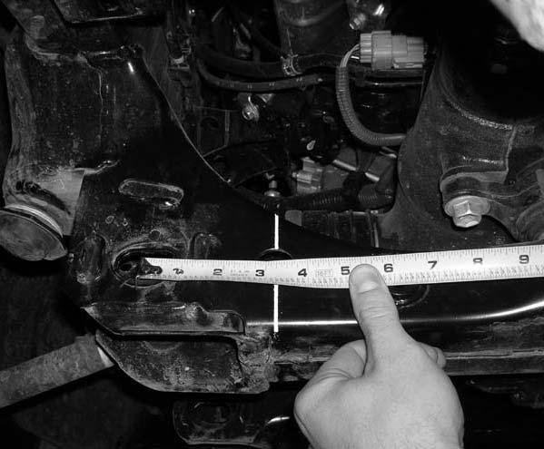
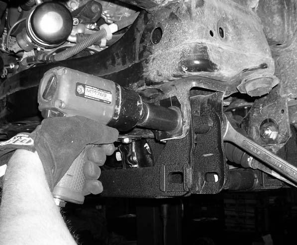
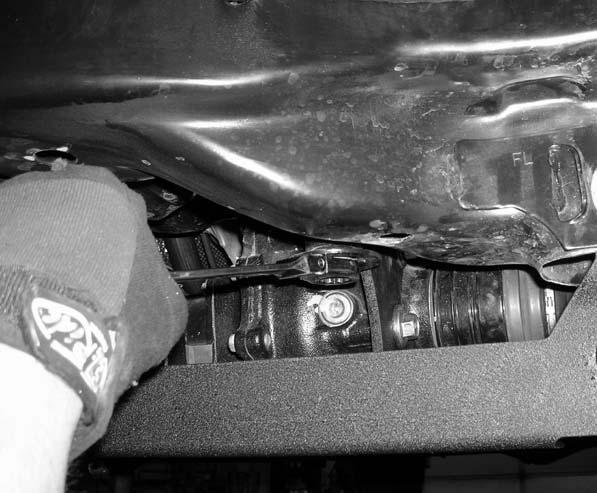
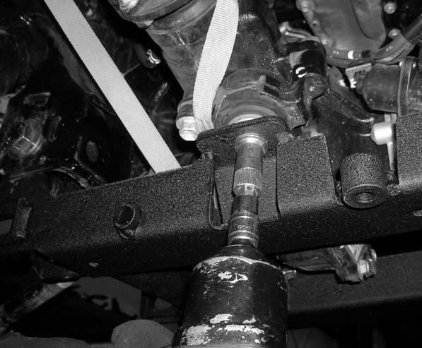
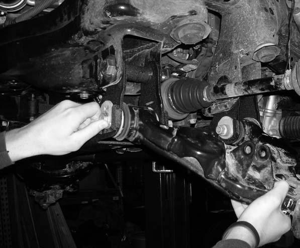
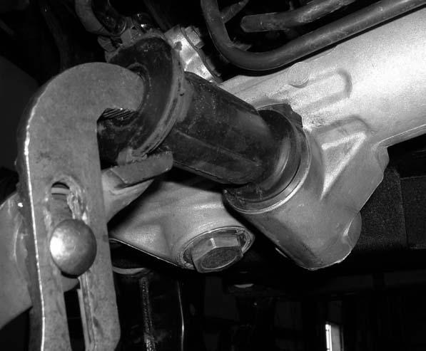
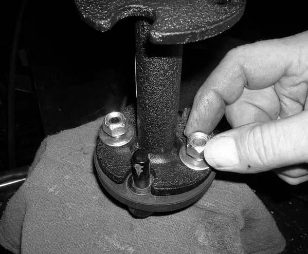
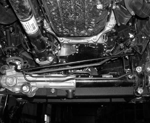
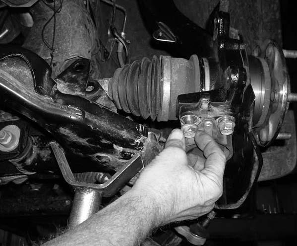
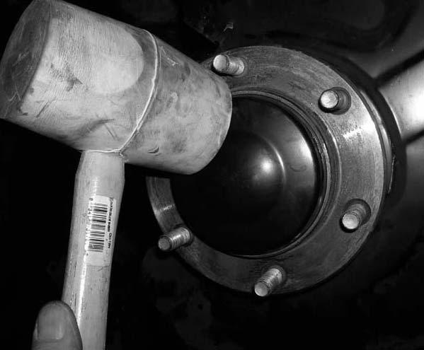
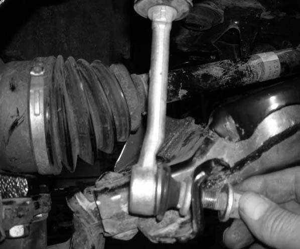
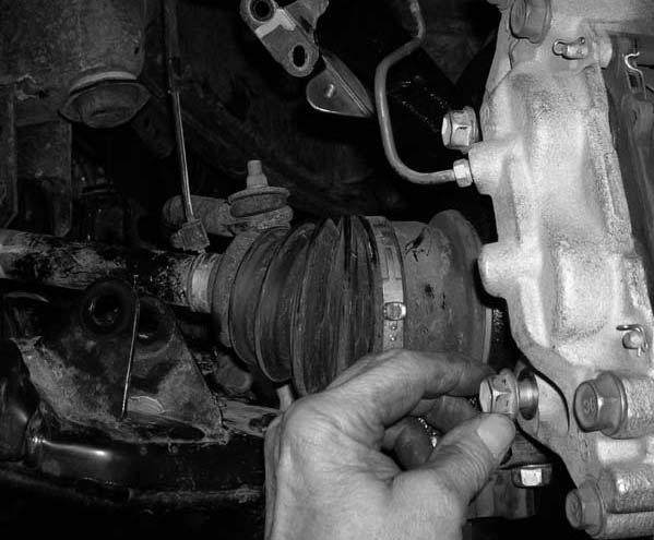
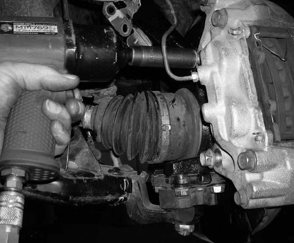
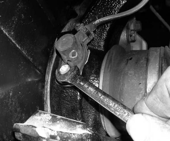
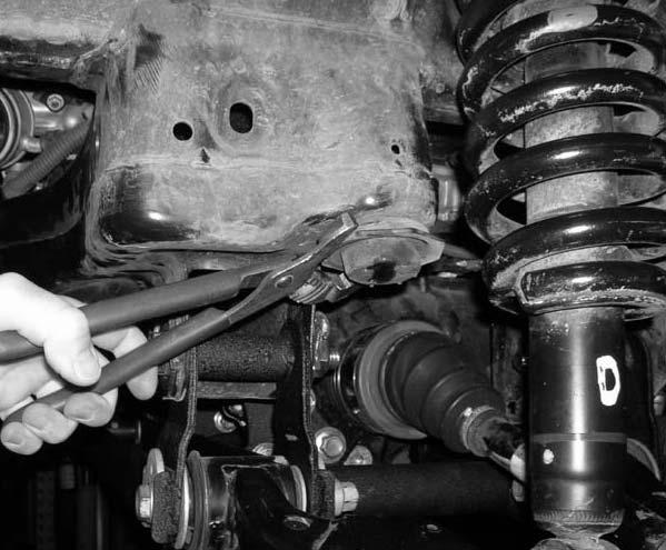
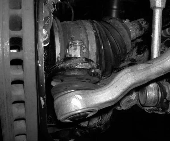
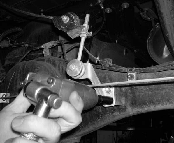
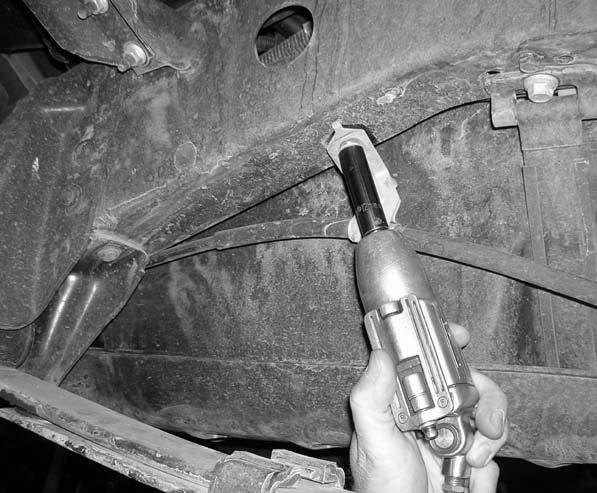
4 Please follow instructions carefully: Before installation begins, measure from the center of the hub, to the bottom of the fender well, and record measurements below. Pre-installation measurements: Driver side front: Passenger side front: Driver side rear: Passenger side rear: At the end of the installation take the same measurements and compare to the pre-installation measurements. Post installation measurements: Driver side front: Passenger side front: Driver side rear: Passenger side rear: Front end installation: 1. To begin installation, block the rear tires of the vehicle so that the vehicle is stable and can t roll backwards. Safely lift the front of the vehicle and support the frame with a pair of jack stands. Place a jack stand on both the driver and the passenger side. Next, remove the front wheels and tires from both sides. 2. Remove the stock front upper skid plate and set the stock front upper skid plate and hardware aside for later re-installation. Photo # 1 3. Working on the driver side, remove the stock lower sway bar end link mounting hardware from the stock location and set aside for later re-installation. Repeat procedure on the passenger side. Photo # 2 4. Working on the driver side, remove the stock mounting hardware that connects the stock end link to the stock sway bar. Save the stock mounting hardware for later re-installation. Repeat procedure on the passenger side. Photo # 3 5. Working on the driver side, remove the stock mounting hardware that attaches the stock sway bar to the stock sway bar mounting location. Save the stock hardware for later re-installation. Repeat procedure on the passenger side. Set the stock sway bar aside for later re-installation. Photo # 4 6. Working on the driver side, remove the stock cotter pin and nut that connects the stock rack and pinion outer ball joint to the stock knuckle. Save the stock cotter pin and nut for later re-installation. Carefully break the stock taper on the stock rack and pinion outer ball joint and remove the stock rack and pinion outer ball joint from the stock knuckle. Special note: Take special care not to rip or tear the stock rack and pinion outer ball joint dust boot. A strike with a hammer will help break the stock tapper. Repeat procedure on the passenger side. Photo # 5 Photo # 6 7. Working on the driver side, remove the stock ABS plug from the stock knuckle. Save the stock hardware for later re-installation. Repeat procedure on the passenger side. Special note: If the vehicle that you are working on is equipped without ABS front brakes, (2) of part # (ABS plugs for new knuckles) need to be purchased as a separate part #. If you have not already ordered the new ABS plugs, please feel free to contact Tuff Country or your local Tuff Country dealer and order the new ABS plugs. If these parts are not installed to the new knuckles, damage will occur to the stock hub liable for assembly and Tuff Country will not be damages. Photo # 7 8. Working on the driver side, remove the stock brake line bracket from the back side of the stock knuckle. Save the stock hardware for later re-installation. Repeat procedure on the passenger side. Photo # 8 9. Working on the driver side, remove the stock ABS line bracket that attaches the stock ABS line to the neck of the stock knuckle. The stock hardware may be discarded. Repeat procedure on the passenger side. Photo # Working on the driver side, remove the stock hardware that connects the stock brake line to the stock upper control arm. The stock hardware may be discarded. Also, at this time, remove the stock brake line bracket from the stock brake line and discard. Repeat procedure on the passenger side. Photo # 10 Photo # Working on the driver side, remove the stock brake line bracket from the stock bump stop bracket. Save the stock hardware for later re-installation. Photo # Working on the driver side, remove the stock cotter pin from the stock upper control arm ball joint. The stock cotter pin may be discarded. Loosen, but do not remove the stock upper control arm castle nut. With a hammer, strike the stock upper control arm next to the stock ball joint to brake the stock upper ball joint tapper. Remove the stock upper castle nut completely. The stock upper castle nut may be discarded. Remove the stock knuckle from the stock upper control arm. Repeat procedure on the passenger side.
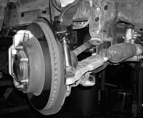
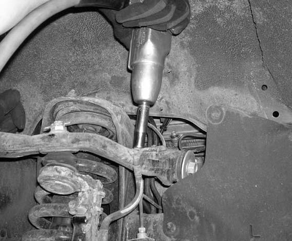
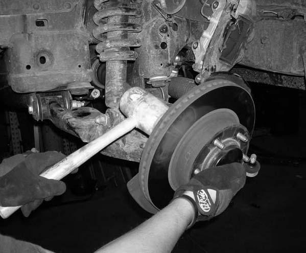
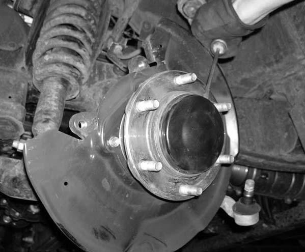
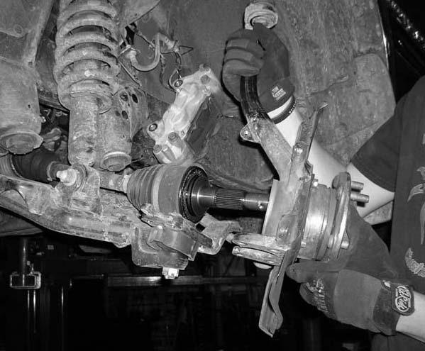
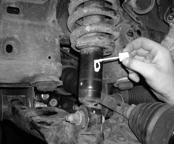
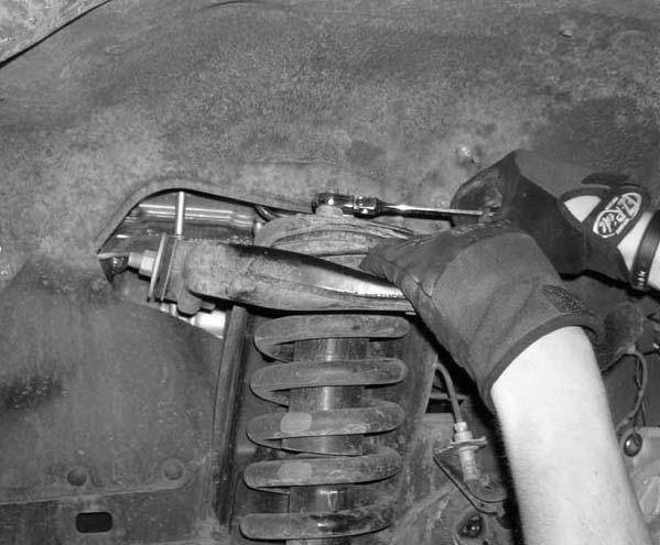
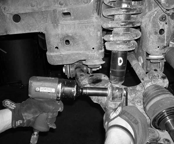
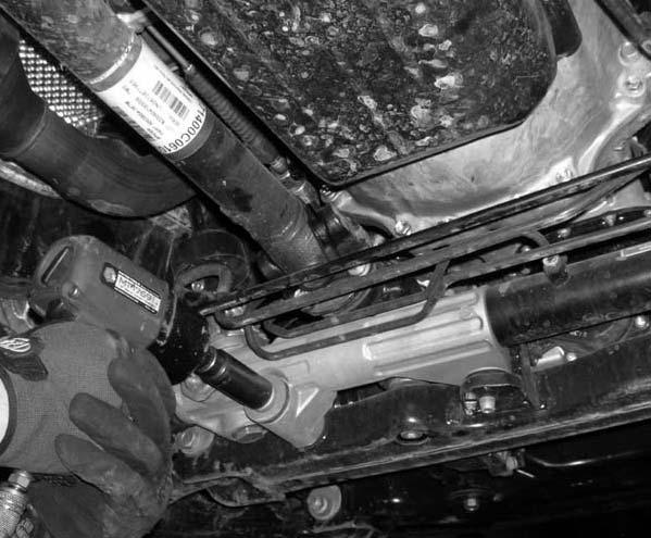
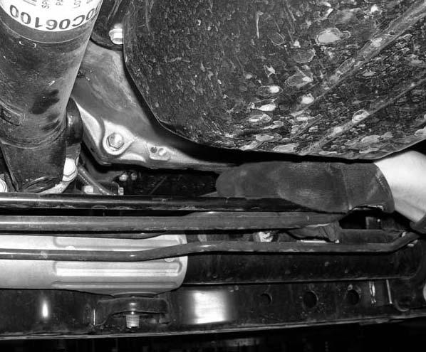
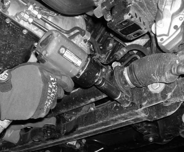
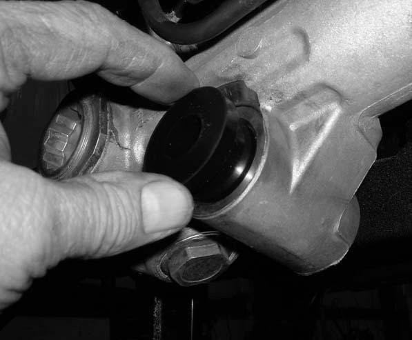
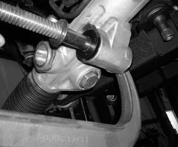
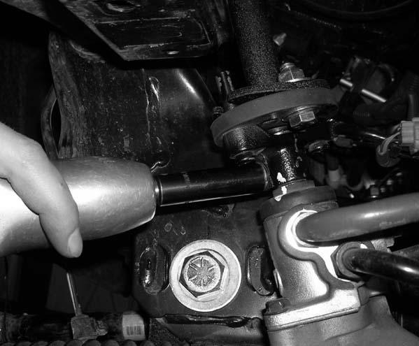
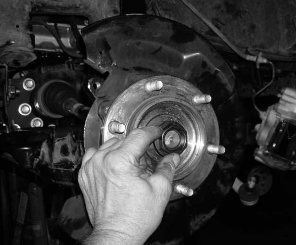
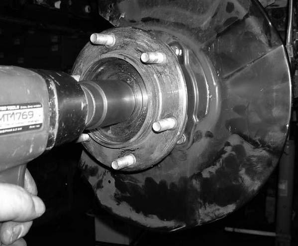
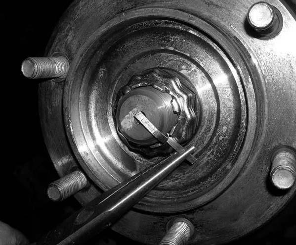
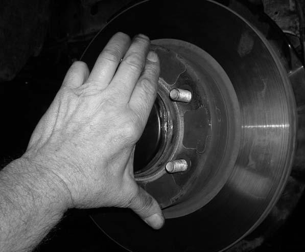
5 Photo # 13 Photo # 14 Photo # Working on the driver side, remove the stock brake caliper from the stock knuckle. Set the stock hardware aside for later re-installation. Carefully tie the stock brake caliper up and out of the way in the stock fender well. Repeat procedure on the passenger side. Photo # Working on the driver side, remove the stock rotor from the stock location and set aside for later re-installation. Repeat procedure on the passenger side. Photo # Working on the driver side and using a flat head screw driver, remove the stock axle cap from the stock hub assembly. Set the stock axle cap aside for later re-installation. Repeat procedure on the passenger side. Photo # Working on the driver side, remove the stock cotter pin and castle nut cap that attached the stock front CV axle to the stock hub assembly. Set the stock cotter pin and castle nut cap aside for later re-installation. Now, remove the stock axle nut and set aside for later re-installation. Repeat procedure on the passenger side. Photo # Working on the driver side, remove the (4) stock mounting bolts that connect the stock lower ball joint plate to the stock knuckle. Save the stock hardware for later re-installation. Carefully remove the stock knuckle from the vehicle and set aside for further instructions. Repeat procedure on the passenger side. Photo # 20 Photo # Working on the driver side and using some white out or a white marker, write a D on the driver side strut. Repeat procedure on the passenger side with a P. Photo # Working on the driver side, remove the (3) stock upper nuts that hold the stock strut assembly into the stock upper pocket. Save the stock hardware for later re-installation. Special note: DO NOT remove the stock upper center nut that holds the stock strut into the stock location. If the nut is removed, a coils spring compressor is going to be needed to replace the stock strut. Repeat procedure on passenger side. Photo # Working on the driver side, remove the stock lower bolt that holds the stock strut into the stock location and save the stock hardware for later re-installation. Repeat procedure on passenger side. Set the driver and passenger side stock struts aside for further instructions. Photo # 24 Photo # Working on the passenger side, remove the stock hardware that connects the stock rack and pinion hi pressure and return lines to the stock rack and pinion. Save the stock hardware for later re-installation. Photo # Working on the driver side, carefully tie the stock rack and pinion to the stock sway bar mount. Repeat procedure on the passenger side. Special note: This is done so that when the rack and pinion is removed from the stock location it will be up out of the way when the stock rear cross member needs to be cut. 23. Working on the driver side, remove the stock hardware that connects the stock rack and pinion to the stock rear cross member. Save the stock hardware for later re-installation. Photo # Locate the center stock bolt that connects the stock rack and pinion to the stock rear cross member. Remove and discard the stock bolt. Photo # Working on the passenger side, remove the stock upper mounting bolt that connects the stock rack and pinion to the stock mounting location. The stock bolt may be discarded. Next, remove the stock lower mounting all thread nut that connects the stock rack and pinion to the stock rear cross member. Save the stock lower mounting nut for later re-installation. Photo # 29 Special note: If you have not already done so, please make sure that the steering wheel is locked. If the steering wheel is not locked and the steering wheel is turned during these next steps, damage may occur to the steering column. 26. Working on the driver side and using some white out or a white marker, scribe a mark on the stock rack and pinion and the stock steering shaft bracket. Photo # Working on the driver side and using some white out or a white marker, scribe a mark on the steering shaft bracket and the spline coupler. Photo # Working on the driver side, remove the stock hardware that connects the stock steering shaft bracket to the stock rack and pinion. Save the stock hardware for later re-installation. Photo # Working on the driver side, remove the lower mounting hardware ONLY that connects the stock steering shaft
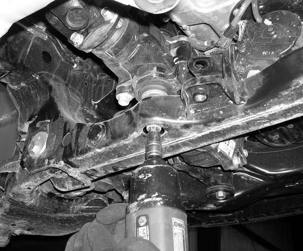
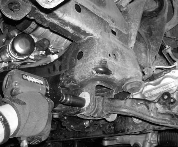
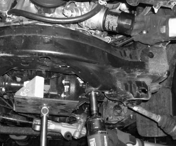
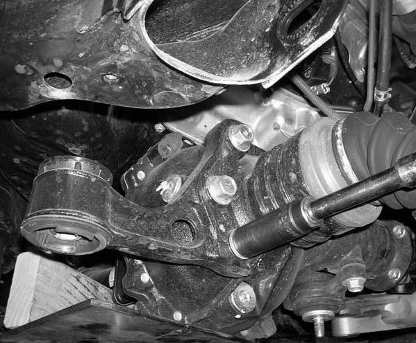
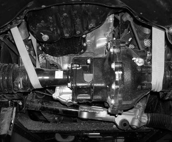
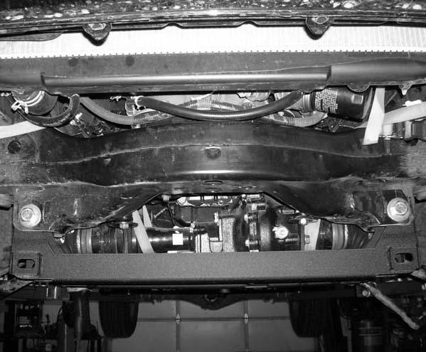
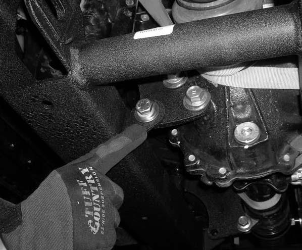
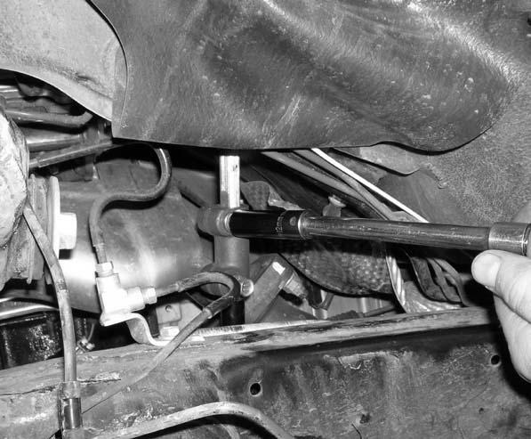
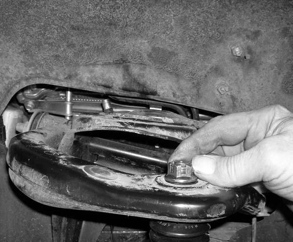
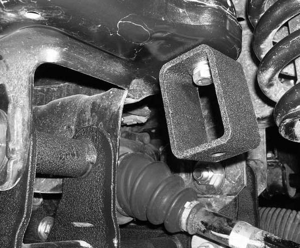
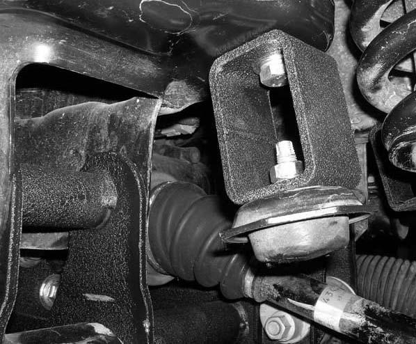
6 bracket to the spline coupler. Save the stock hardware for later re-installation. Remove the stock steering shaft from the vehicle and set aside for further instructions. Special note: To make access to this hardware easier, pull back the rubber splash guard in the stock driver side fender well. Photo # Working on the center of the of the rear cross member, remove the stock mounting nut that connects the stock front differential to the stock rear cross member. Set the stock hardware aside for later re-installation. Photo # Working on the driver side, remove the stock lower control arm mounting cams from the stock front and rear mounting locations. Save the stock hardware for later re-installation. Set the stock lower control arms aside for later re-installation. Repeat procedure on the passenger side. Photo # Working on the driver side, measure from the stock rear lower control arm mounting point towards the inside of the vehicle 3 1/4. Scribe a mark on the stock rear cross member. Using a suitable cutting tool, carefully cut the stock rear cross member. Special note: Tuff Country does not recommend using a torch when making this cut. Tuff Country recommends using a sawzall to make this cut. Also, take special care not to cut any lines, hoses or wires. Photo # Working on the passenger side, measure from the stock rear lower control arm mounting point towards the inside of the vehicle 5 3/4. Scribe a mark on the stock rear cross member. Using a suitable cutting tool, carefully cut the stock rear cross member. Special note: Tuff Country does not recommend using a torch when making this cut. Tuff Country recommends using a sawzall to make this cut. Also, take special care not to cut any lines, hoses or wires. The stock rear cross member that was cut out may be discarded. Photo # 37 Photo # Place a hydraulic floor jack under the front differential and carefully raise up on the hydraulic floor jack until it makes contact with the front differential. 35. Working on the driver side, remove the stock mounting hardware that connects the stock driver side differential bracket to the stock front cross member. Save the stock hardware for later re-installation. Repeat procedure on the passenger side. Photo # Working on the driver side, remove the (3) stock bolts that connect the driver side differential bracket to the stock front differential. Save the stock hardware for later re-installation. Repeat procedure on the passenger side. Special note: On the passenger side, the stock differential bracket is attached to the stock front differential with (2) stock bolts. Photo # 40 Photo # With a tie down strap, carefully tie the stock front differential to the stock frame rail. This is done so the front differential will hang. With the front differential hanging, remove the hydraulic floor jack from under the front differential. Photo # Locate the new driver and passenger side differential relocation brackets. Locate (4) PB2408 poly bushings and (2) S10082 sleeves from hardware bag 55907NB1. Install the new poly bushings into the new driver and passenger side differential relocation brackets. Next, install the new sleeves into the newly installed poly bushings. Special note: Make sure to use a lithium or moly base grease prior to inserting the new bushings into the new driver and passenger side differential relocation brackets. This will increase the life of the bushings as well as prevent squeaking. 39. Locate the new driver side differential relocation bracket. Locate the (3) stock mounting bolts that were removed in step # 36. Also, locate (3) 9/16 USS flat washers from hardware bag 55907NB. Working on the driver side, install the new driver side differential relocation bracket to the stock front differential and secure using the stock mounting bolts and the new 9/16 USS flat washers. Do not tighten at this point. Photo # Locate the new passenger side differential relocation bracket. Locate the (2) stock mounting bolts that were removed in step # 36. Also locate (2) 9/16 USS flat washers from hardware bag 55907NB. Working on the passenger side, install the new passenger side differential relocation bracket to the stock front differential and secure using the stock mounting bolts and the new 9/16 USS flat washers. Do not tighten at this point. Photo # Locate the stock driver and passenger side mounting hardware that attached the stock differential brackets to the stock front cross member that were removed in step # 35. Working on the driver side, install the new driver side differential relocation bracket to the stock front cross member using the stock hardware. Do not tighten at this point. Repeat procedure on the passenger side. 42. Locate (2) 3/4 x 5 1/2 bolts, (2) 3/4 x 5 bolts, (8) 3/4 flat washers and (4) 3/4 unitorque nuts from hardware bag 55907NB. Also, locate the new one piece lower sub frame. Install the new one piece lower sub frame into the stock
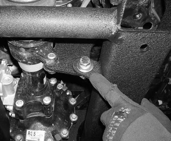
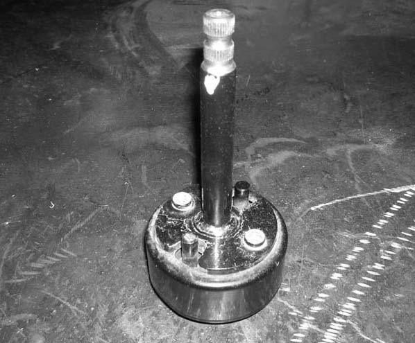
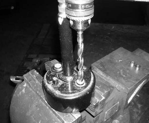
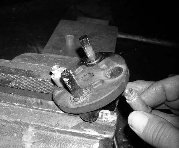
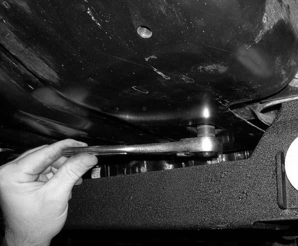
7 front and rear lower control arm pockets and secure using the new 3/4 x 5 1/2 bolts into the front location and the new 3/4 x 5 bolts and hardware into the rear location. Special note: Do not tighten at this point. Also, when installing the new one piece lower sub frame, make sure that the rear mounting stud on the rear portion of the front differential seats properly into the new one piece lower sub frame. Photo # Locate (1) 1/2 x 1 1/2 bolt, (2) 7/16 USS flat washers, and (1) 1/2 unitorque nut from hardware bag 55907NB. Working on the driver side, install the newly installed one piece lower sub frame to the newly installed driver side differential relocation bracket and secure using the new 1/2 x 1 1/2 bolt and hardware. Special note: Do not tighten at this point. Also, when installing the new driver side differential relocation bracket to the new one piece lower sub frame, make sure that the new driver side differential relocation bracket is installed towards the inside of the new differential tabs on the new one piece lower sub frame. Photo # Locate (1) 1/2 x 1 1/2 bolt, (2) 7/16 USS flat washers, and (1) 1/2 unitorque nut from hardware bag 55907NB. Working on the passenger side, install the newly installed one piece lower sub frame to the newly installed passenger side differential relocation bracket and secure using the new 1/2 x 1 1/2 bolt and hardware. Special note: Do not tighten at this point. Also, when installing the new passenger side differential relocation bracket to the new one piece lower sub frame, make sure that the new passenger side differential relocation bracket is installed towards the inside of the new differential tabs on the new one piece lower sub frame. Photo # Locate the stock mounting hardware that was removed in step # 30. Secure the rear mounting stud on the rear portion of the front differential to the new one piece lower sub frame using the stock hardware. Do not tighten at this point. 46. Move back to the newly installed 3/4 x 5 bolts and 3/4 x 5 1/2 bolts securing the new one piece lower sub frame into the new location and add some thread locker or lock tite. Torque the new 3/4 bolts and hardware to 125 ft lbs. Photo # Move back to the (3) stock bolts holding the newly installed driver side differential relocation bracket to the stock front differential and add some thread locker or lock tite. Torque to 85 ft lbs. Repeat procedure on the passenger side. Photo # Move back to the new 1/2 x 1 1/2 bolts holding the newly installed driver side differential relocation bracket to the tab on the newly installed one piece sub frame and add some thread locker or lock tite. Torque to 75 ft lbs. Repeat procedure on the passenger side. Photo # Move back to the stock hardware holding the newly installed driver side differential relocation bracket to the stock front cross member and add some thread locker or lock tite. Torque to 85 ft lbs. Repeat procedure on the passenger side. Photo # Move back to the rear mounting stud on the rear portion of the front differential and add some thread locker or lock tite. Torque to 75 ft lbs. Photo # It is now ok to remove the tie down strap holding the stock front differential to the stock frame rail. 52. Locate the stock lower control arm mounting cams and the stock lower control arms that were removed in step # 31. Working on the driver side, install the stock lower control arm to the newly installed one piece lower sub frame using the stock cams. Do not tighten at this point. Repeat procedure on the passenger side. Photo # Working on the driver side of the stock rack and pinion, remove the stock rubber bushing and discard. Photo # Working on the center of the stock rack and pinion, remove the stock rubber bushing and discard. Photo # Locate (2) new MO3778 poly bushings and (1) S10136 sleeve from hardware bag 55907NB1. Working on the center of the stock rack and pinion, install the new bushings and sleeves into the stock rack and pinion. Special note: Make sure to use a lithium or moly base grease prior to inserting the new bushings into the stock rack and pinion. This will increase the life of the bushings as well as prevent squeaking. Photo # Locate (2) MO2382 poly bushings and (1) S10139 sleeve from hardware bag 55907NB1. Working on the driver side of the stock rack and pinion, install the new bushings and sleeves into the stock rack and pinion. Special note: Make sure to use a lithium or moly base grease prior to inserting the new bushings into the stock rack and pinion. This will increase the life of the bushings as well as prevent squeaking. Photo # 57 Photo # Locate the stock steering shaft extension bracket. Place the stock steering shaft bracket into a vise. Carefully drill out the stock rivets holding the stock steering shaft to
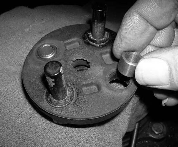
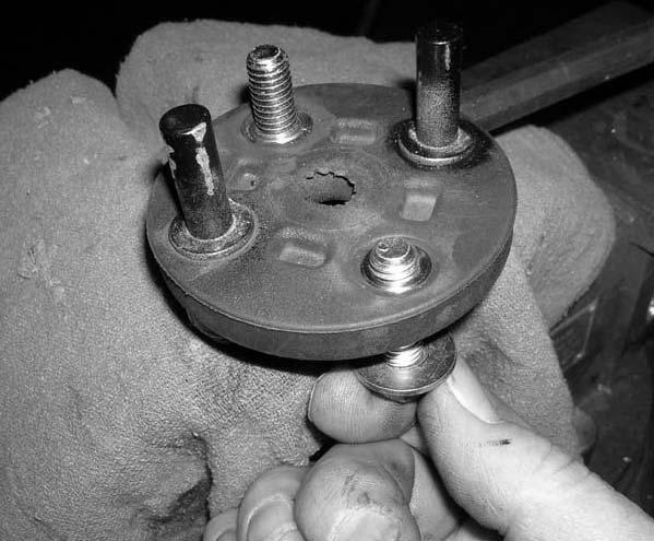
8 the dust cover. Photo # 59 Photo # Once the rivets have been drilled out, remove the stock steering shaft from the dust cover and set aside for further instructions. Next, remove the dust cover and discard. Photo # 61 Photo # Remove the bottom portion of the stock rivets that were drilled out early in the instruction manual and discard. Photo # Locate (2) S10108 sleeves from hardware bag 55907NB1. Install the new sleeves into the rubber portion of the stock lower rack and pinion bracket. Photo # Locate the new steering shaft extension bracket. Also, locate (2) 3/8 x 1 bolts, (4) 5/16 USS flat washers and (2) 3/8 unitorque nuts from hardware bag 55907NB. Install the new steering shaft extension bracket to the rubber portion of the stock lower rack and pinion bracket and secure using the new 3/8 x 1 bolts and hardware. Make sure to use thread locker or lock tite and torque to 28 ft lbs. Special note: The new steering shaft extension bracket has a bent plate on one side, this side needs to be installed towards the rubber portion of the stock lower rack and pinion bracket. Photo # 65 Photo # 66 Photo # Locate the stock steering shaft extension bracket. Also, locate (2) 3/8 x 1 bolts, (4) 5/16 USS flat washers and (2) 3/8 unitorque nuts from hardware bag 55907NB. Install the stock steering shaft to the newly installed steering shaft extension bracket and secure using the new 3/8 x 1 bolt and hardware. Make sure to use thread locker or lock tite and torque to 28 ft lbs. Photo # 68 Photo # Locate the new passenger side rack and pinion support bracket. Working on the passenger side, install the new passenger side rack and pinion support bracket to the stock rack and pinion bolt. Photo # Locate the stock driver side rack and pinion mounting hardware that was removed in step # 23. Also, locate (2) S10077 over size washers from hardware bag 55907NB1. Working on the driver side, install the stock rack and pinion to the driver side of the newly installed one piece sub frame and secure using the stock hardware and the new over size washers. Do not tighten at this point. Special note: make sure to install one of the over size washers between the stock rack and pinion and the one piece sub frame. Photo # Locate the center rack and pinion bracket. Locate (1) 9/16 x 2 1/2 bolts, (1) 9/16 lock washer, (1) 1/2 USS flat washer, (2) 1/2 x 1 1/2 bolts, (4) 7/16 USS flat washers and (2) 1/2 unitorque nuts from hardware bag 55907NB. Also, locate (2) S10140 (9/16 fender washers) from hardware bag 55907NB1. Working on the center of the newly installed sub frame, install the center rack and pinion bracket to the sub frame and secure using the new 1/2 x 1 1/2 bolts and hardware. Special note: make sure to install the bracket with the weld on the spud towards the ground. Do not tighten at this point. Next, install the stock rack and pinion to the new center rack and pinion bracket using the new 9/16 x 2 1/2 bolts, hardware and 9/16 fender washers. Special note: The fender washers need to be installed on top of the stock rack and pinion and between the stock rack and pinion and the new center rack and pinion bracket. Do not tighten at this time. Special note: The bolt will be installed from the top of the rack and pinion downward. Photo # Locate the stock passenger side rack and pinion all thread nut that was removed in step # 25. Also, locate (1) 9/16 x 2 1/2 bolt, (1) 9/16 lock washer from hardware bag 55907NB. Remove and re-install the stock rack and pinion mounting bracket in the upside down position around the stock rack and pinion bushing. Secure the upper part of the stock rack and pinion bracket to the stock bolt and secure using the stock all thread nut. Do not tighten at this point. Secure the bottom part of the stock bracket to the newly installed one piece sub frame using the new 9/16 x 2 1/2 bolt and hardware. Do not tighten at this point. Photo # Locate (1) BLR09 (relocation bracket) from hardware bag 55907NB1. Locate (1) 5/16 x 1 bolt, (2) 1/4 USS flat washers and (1) 5/16 unitorque nut from hardware bag 55907NB. Also, locate the stock rack and pinion hi pressure line mounting hardware that was removed in step # 21. Install the new relocation bracket to the stock rack and pinion hi pressure lines and secure using the new 5/16 x 1 bolt and hardware. Do not tighten at this point. Next secure the previously installed relocation bracket to the stock rack and pinion and secure using the stock hardware. Make sure to use thread lock or lock tite and torque to 12 ft lbs. Move back to the new 5/16 x 1 bolt installed earlier in this step and add some thread locker or lock tite and torque the new 5/16 x 1 bolt to 14 ft lbs. Photo # Locate the new steering shaft extension bracket and the stock steering shaft. Also, locate the stock spline coupler hardware that was removed in step # 29. Slide the stock steering shaft up into the stock spine coupler. Install the stock hardware but do not tighten at this point. Special note: make sure that the marks that were scribed in
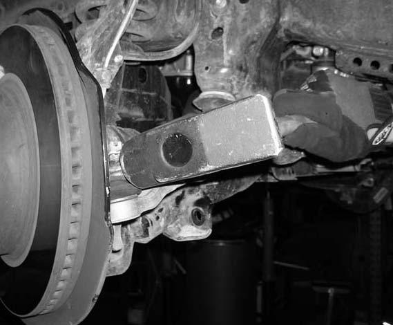
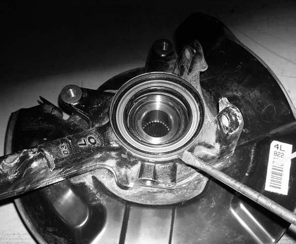
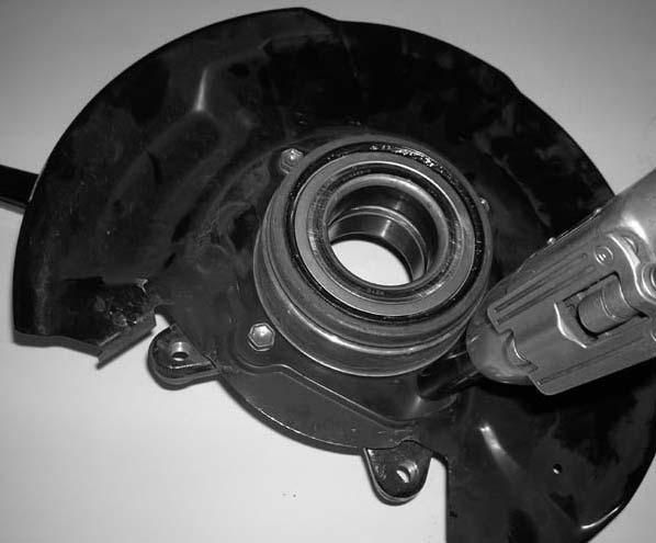
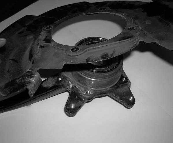
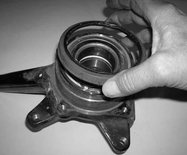
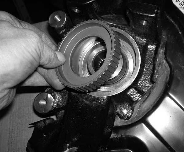
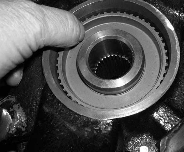
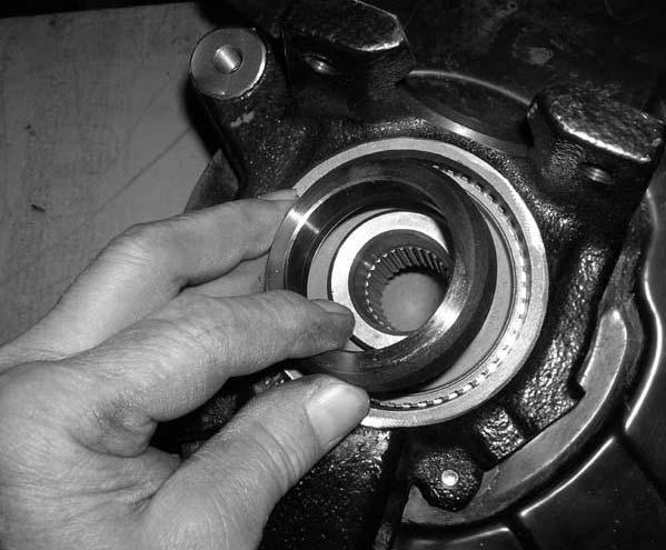
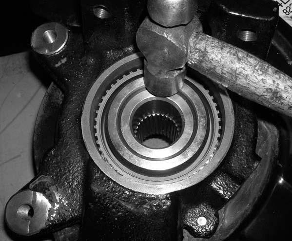
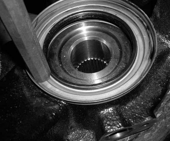
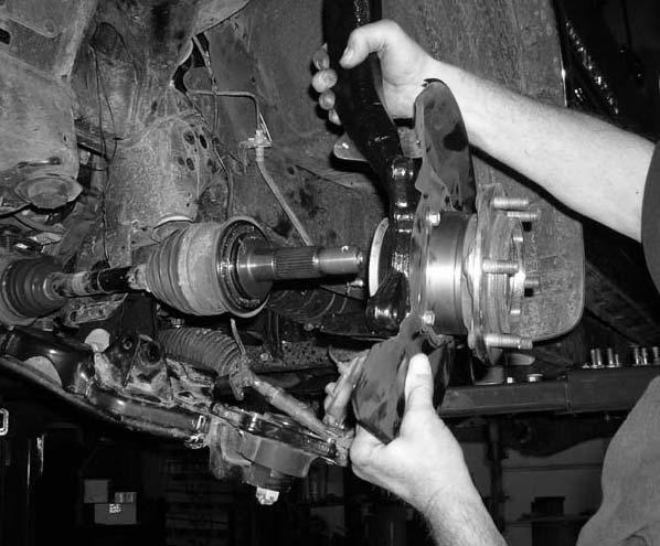
9 step # 27 line up with each other. 69. Install the stock lower steering shaft bracket to the stock rack and pinion. Add some thread locker or lock tite to the stock bolt and torque to 18 ft lbs. Special note: make sure that the marks that were scribed in step # 26 line up with each other. Photo # 74 Photo # Move back to the stock steering shaft spline coupler mounting bolt and add some thread locker or lock tite and torque the stock bolt to 18 ft lbs. Special note: It would be a good idea to check the torque on the upper stock bolt on the stock spline coupler at this point. Photo # Move back to the stock driver side bolt holding the stock rack and pinion to the new sub frame and add some thread locker or lock tite and torque to 110 ft lbs. Move back to the passenger side rack and pinion and add some tread locker or lock tite to the stock all thread nut and the new 9/16 x 2 1/2 bolt and torque both to 85 ft lbs. Move to the center rack and pinion bracket attached to the new sub frame and add some thread locker or lock tite to the 1/2 x 1 1/2 bolt and torque to 65 ft lbs. Now move back to the 9/16 x 2 1/2 bolt holding the stock rack and pinion to the new center rack and pinion bracket and torque to 85 ft lbs. Special note: During the installation of the stock hub assembly to the new knuckles, special care needs to be taken not to damage the hub assembly or knuckle. We need to make sure that we press the knuckle onto the hub assembly NOT THE HUB ASSEMBLY ONTO THE KNUCKLE. If you have any questions, please call the Tech Tuff Country. (801) Locate the stock driver side knuckle that was removed from step # 17. Working on the stock driver side knuckle, carefully remove the inner stock oil seal from the stock knuckle. Special Note: Take special care not to damage the stock oil seal during removal. Set the stock oil seal aside for later instructions. Photo # 77 Photo # Working on the stock driver side knuckle, carefully press out the stock hub assembly from the stock knuckle. Special Note: Tuff Country highly recommends that this step be performed by a capable installer or technician. If special care is not taken, the stock hub assembly, ABS speed sensor rotor or bearing spacer may be damaged. If the stock hub assembly, ABS speed sensor rotor or bearing spacer are damaged a new hub assembly, ABS speed sensor or bearing spacer will need to be purchased from your local dealer. Once the stock hub assembly has been pressed out, set the stock hub assembly, ABS speed sensor rotor and bearing spacer aside for later instructions. Photo # 79 Photo # Working on the stock driver side knuckle, remove the (4) stock bolts holding the stock dust cover to the stock driver side knuckle. Set the stock bolts and dust cover aside for later instructions. Also, at this time remove the outer stock oil seal from the stock knuckle. Special note: Take special care not to damage the stock oil seal during removal. Set the stock oil seal aside for later instructions. The stock knuckle may be discarded. Photo # 81 Photo # 82 Photo # 83 Photo # Locate the new driver side knuckle. Locate the stock outer oil seal, the (4) stock bolts and the stock dust cover that were removed in step # 73. Install the stock outer oil seal to the new knuckle. Special note: Take special care not to damage the stock oil seal during installation. Next, install the stock dust cover to the new driver side knuckle using the stock hardware. Special note: Make sure to use thread locker or lock tite. Torque the stock hardware to 13 ft lbs. Photo # 85 Photo # Locate the stock hub assembly, the stock ABS speed sensor rotor and bearing spacer that were removed from step # 73. Carefully press the new knuckle onto the stock hub assembly. Special note: Tuff Country highly recommends that this step be performed by a capable installer or technician. If special care is not taken, the stock hub assembly or new driver side knuckle may be damaged. If the stock hub assembly or the new driver side knuckle are damaged, new parts will need to be purchased. Re-install the stock ABS speed sensor and bearing spacer into the new driver side knuckle. Special note: Tuff Country highly recommends that this step be performed by a capable installer or technician. If special care is not taken, the stock ABS speed sensor or bearing spacer may be damaged. If the stock ABS speed sensor rotor or bearing spacer are damaged, new ABS speed sensor rotor or bearing spacer will need to purchased. Photo # 87 / Photo # 88 Photo # 89 / Photo # 90 Photo # Locate the stock inner oil seal that was removed from step # 72. Carefully re-install the stock inner oil seal to the new driver side knuckle. Special note: Take special care not to damage the stock oil seal during installation. Set the new driver side knuckle aside for later re-installation. Photo # 92 Photo # 93
10 78. Repeat steps for the passenger side knuckle. 79. Locate (1) wire tie from hardware bag 55907NB1. Locate the new driver side knuckle. Remove the new upper ball joint castle nut and set aside for later installation. Install the wire tie around the new upper ball joint dust boot on the new driver side knuckle. Working on the driver side, carefully slide the stock drive shaft into the new driver side knuckle. Secure the new driver side knuckle to the stock upper control arm and finger tighten the new upper ball joint castle nut that was removed earlier in this step. Photo # 94 Photo # Locate the (4) stock bolts that connected the stock lower control arm ball joint plate to the stock knuckle that were removed from step # 17. Secure the stock lower control arm ball joint plate to the new driver side knuckle using the stock hardware. Make sure to use thread locker or lock tite. Torque to 39 ft lbs. Photo # Locate (1) new cotter pin from hardware bag 55907NB1. Working on the driver side, torque the new upper castle nut that connects the upper ball joint to the stock driver side upper control arm to 80 ft lbs. Making sure that the hole in the new castle nut and the new upper ball joint are lined up, install the new cotter pin. Special note: If the new cotter pin can not be installed because the hole in the new castle nut does not line up with the new ball joint, DO NOT loosen the new castle nut so that the cotter pin can fit, tighten the new castle nut some more so that the new cotter pin can be installed. Photo # 97 Photo # Locate the stock cotter pin, stock lock cap and the stock axle nut that was removed in step # 16. Working on the driver side, secure the stock drive shaft to the stock hub assembly using the stock nut. Special note: Make sure to use thread locker or lock tite. Torque to 174 ft lbs. Next, install the stock lock cap and the stock cotter pin. Photo # 99 Photo # 100 Photo # Locate the stock grease cap that was removed in step # 15. Working on the driver side, re-install the stock grease cap into the stock location. Photo # Repeat steps for the passenger side knuckle. 85. Locate the new driver and passenger side sway bar relocation brackets. Also, locate (4) 3/8 x 1 1/4 bolts, (8) 5/16 USS flat washers and (4) 3/8 unitorque nuts from hardware bag 55907NB. Working on the driver side, install the new driver side sway bar relocation bracket to the stock frame mount location and secure using the new 3/8 x 1 1/4 bolts and hardware. Special note: Do not tighten at this point. Repeat procedure on the passenger side. Photo # Locate the stock sway bar and the stock hardware that was removed from step # 5. Working on the driver side, install the stock sway bar to the newly installed sway bar relocation bracket and secure using the stock hardware. Do not tighten at this point. Repeat procedure on the passenger side. Photo # Locate the stock sway bar end link hardware and the stock sway bar end links that were removed from steps # 3 & 4. Working on the driver side, install the stock sway bar to the stock lower control arm using the stock hardware. Make sure to use thread locker or lock tite. Torque to 22 ft lbs. Next secure the stock end link to the stock sway bar and secure using the stock hardware. Make sure to use thread locker or lock tite and torque to 22 ft lbs. Repeat procedure on the passenger side. Photo # Working on the driver side, add some thread locker or lock tite to the new hardware attaching the new sway bar relocation bracket to the stock location and torque to 24 ft lbs. Now add some thread locker or lock tite to the stock hardware that is attaching the stock sway bar to the newly installed sway bar relocation bracket and torque to 18 ft lbs. 89. Locate the stock rotors that were removed from step # 14. Working on the driver side, re-install the stock rotor to the stock hub assembly. Repeat procedure on the passenger side. Photo # Locate the stock hardware that attached the stock brake caliper to the stock knuckle that was removed from step # 13. Working on the driver side, carefully untie the stock brake caliper that was tied in the stock fender well and attach the stock brake caliper to the new driver side knuckle. Special note: Make sure to use thread locker or lock tite. Torque to 90 ft lbs. Repeat procedure on the passenger side. Photo # 107 Photo # Locate the stock brake line bracket and hardware that was attached to the stock knuckle that was removed in step # 8. Working on the driver side, attach the stock brake line bracket to the newly installed knuckle using the stock hardware. Special note: Make sure to use thread locker of lock tite. Torque to 10 ft lbs. Repeat procedure on the passenger side. Photo # 109
11 92. Locate the stock ABS line hardware that connected the stock ABS line to the stock knuckle that was removed from step # 7. Working on the driver side, attach the stock ABS line to the newly installed knuckle using the stock hardware. Special note: Make sure to use thread locker or lock tite. Torque to 71 in lbs. Repeat procedure on the passenger side. Special note: If the vehicle that you are working on is equipped without ABS front brakes, (2) of part # (ABS plugs for new knuckles) need to be purchased as a separate part #. If you have not already ordered the new ABS plugs, please feel free to contact Tuff Country or your local Tuff Country dealer and order the new ABS plugs. If these parts are not installed to the new knuckles, damage will occur to the stock hub assembly and Tuff Country will not be liable for damages. Photo # 110 Photo # Working on the driver side, attach the stock ABS line clip into the stock brake line bracket that attaches to the back side of the newly installed driver side knuckle. Repeat procedure on the passenger side. Photo # Locate (2) front brake line relocation brackets from hardware bag 55907NB1. Locate (2) 5/16 x 3/4 bolts, (4) 1/4 USS flat washers and (2) 5/16 unitorque nuts from hardware bag 55907NB. Also, locate the stock brake line bracket hardware that was removed in step # 11. Working on the driver side, attach the new brake line relocation bracket to the stock location and secure using the stock hardware. Do not tighten at this point. Now attach the stock brake line bracket to the newly installed brake line relocation bracket using the new 5/16 x 3/4 bolt and hardware. Make sure to use thread locker or lock tite and torque to 14 ft lbs. Add some thread locker or lock tite to the stock bolt holding the new brake line relocation bracket to the stock location and torque to 12 ft lbs. Repeat procedure on the passenger side. Photo # Locate the (2) shock ties from hardware bag 55907NB1. Working on the driver side, tie the stock brake line bracket and the stock ABS lines together. Cut off the excess part of the shock tie. Repeat procedure on the passenger side. Photo # Locate (2) new front upper strut spacers. Locate the stock hardware that connected the stock strut into the stock location that was removed from step # 19. Locate the stock driver side strut that was removed in step # 20. Working on the driver side strut, install the new front upper strut spacer to the stock strut using the stock hardware. Special note: Make sure to use thread locker or lock tite. Torque to 38 ft lbs. Repeat procedure on the passenger side strut. Photo # Locate (6) 3/8 nylock nuts, (6) 5/16 flat washers and (6) 3/8 lock washers from hardware bag 55907NB. Working on the driver side, install the stock driver side strut into the stock upper location, secure using the new 3/8 hardware. Special note: Make sure to use thread locker or lock tite. Torque to 38 ft lbs. Also, make sure that you install the driver side strut on the driver side of the vehicle and the same goes for the passenger side strut. Refer to the markings that were made in step # 18. Repeat procedure on passenger side. Photo # Locate the stock lower hardware that attached the stock strut to the stock lower control arm that was removed from step # 20. Working on the driver side, install the lower eyelet of the stock strut into the stock location using the stock hardware. Special Note: Make sure to use thread locker or lock tite. Torque to 85 ft lbs. Repeat procedure on the passenger side. Photo # Working on the driver side, remove the stock front bump stop from the stock location. Save the stock bump stop for later re-installation. Repeat procedure on the driver side rear bump stop. Repeat procedure on the passenger side. Photo # Locate (4) new bump stop relocation brackets. Locate (4) 10 mm flat washers, (4) 10 mm lock washers and (4) 10 mm x 25 mm fine bolts from hardware bag 55907NB. Working on the driver side, install the new bump stop relocation brackets to the stock front and rear location and secure using the new 10 mm x 25 mm fine bolts and hardware. Make sure to use thread locker or lock tite and torque to 28 ft lbs. Repeat procedure on the passenger side. Photo # Locate (4) 10 mm fine nuts, (4) 10 mm flat washers and (4) 10 mm lock washers from hardware bag 55907NB. Also, locate the stock front and rear bump stops that were removed in step # 99. Working on the driver side, install the stock front and rear bump stops to the newly installed front and rear bump stop relocation brackets and secure using the new 10 mm hardware. Make sure to use thread locker or lock tite and torque to 28 ft lbs. Repeat procedure on the passenger side. Photo # Locate the stock skid plate that was removed in step # 2. Place the stock skid plate flat on a work bench. Working on the driver side of the stock skid plate and referring to Photo # 121 measure from the leading edge of the stock skid plate towards the back of the stock skid plate 1 1/4 and scribe a mark with white out or a white marker. Now referring to Photo # 122 measure 1 1/2 from the leading edge towards the inside of the vehicle and scribe a mark. Repeat procedure on the passenger side of the stock from skid plate. With a suitable cutting tool, carefully notch
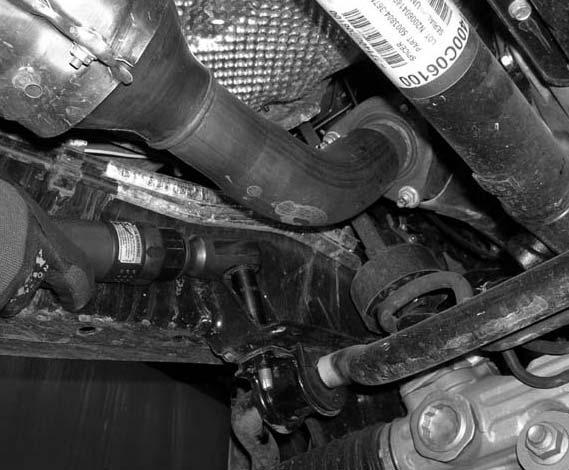
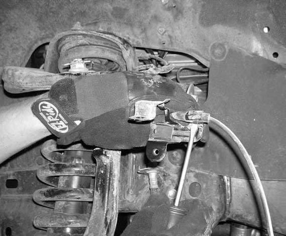
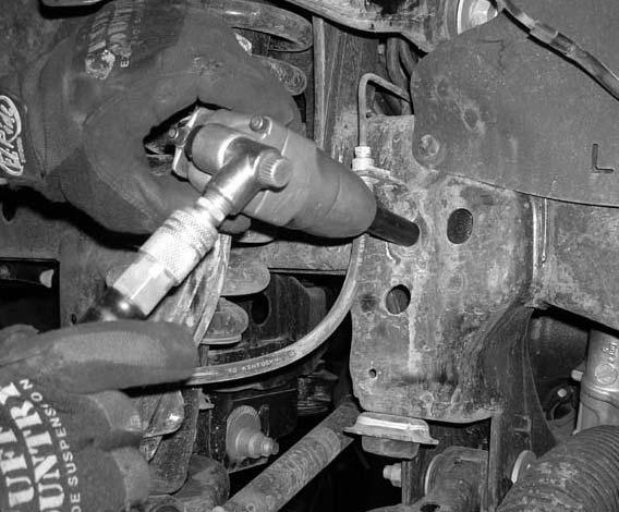
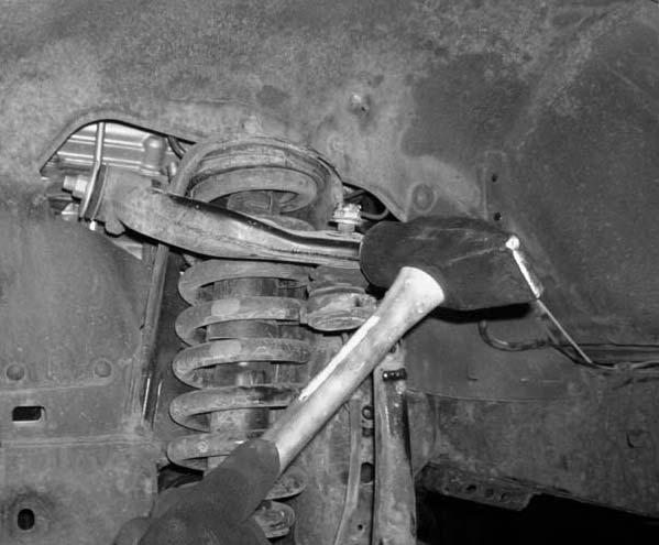
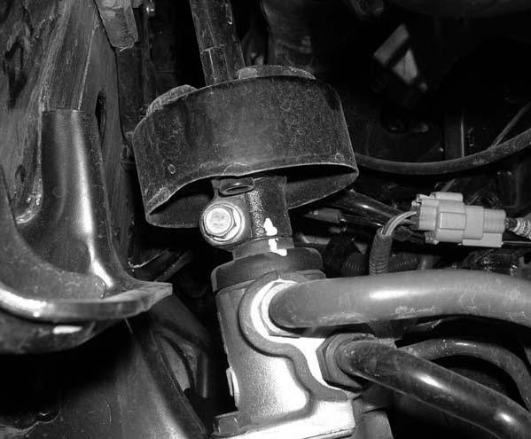
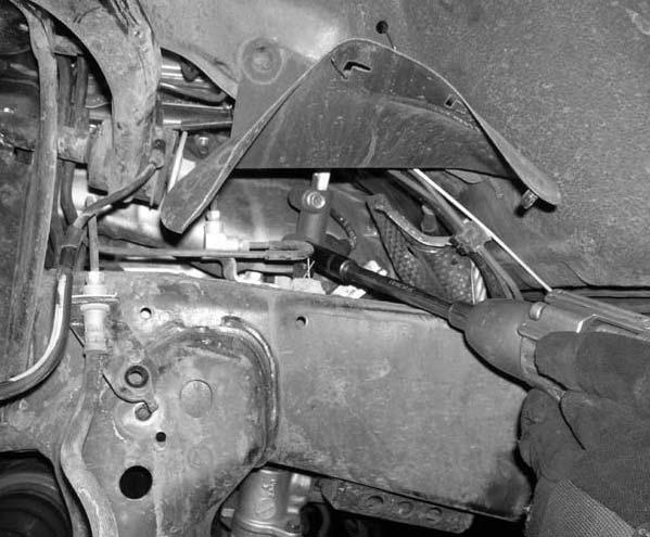
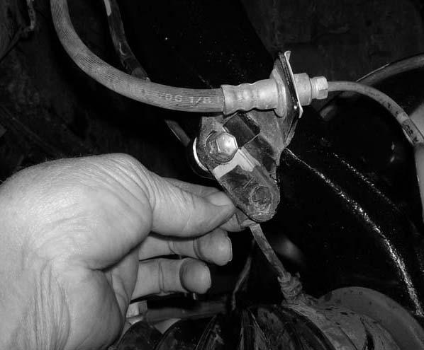
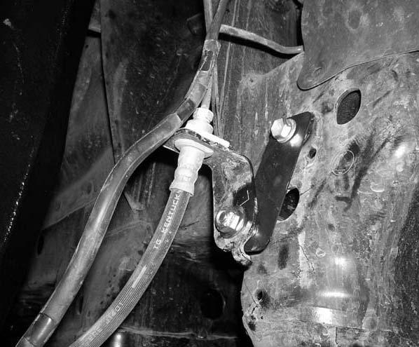
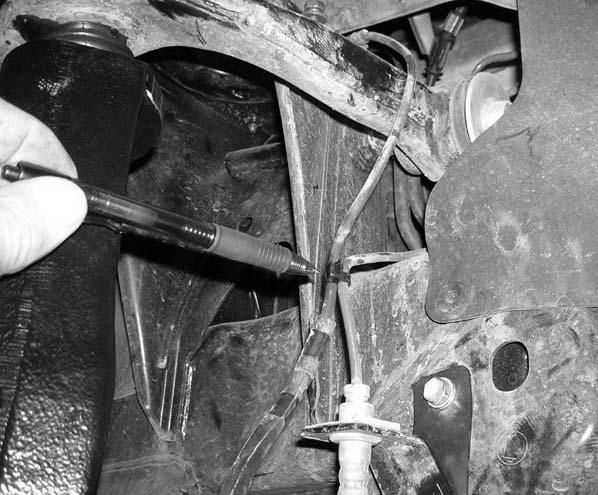
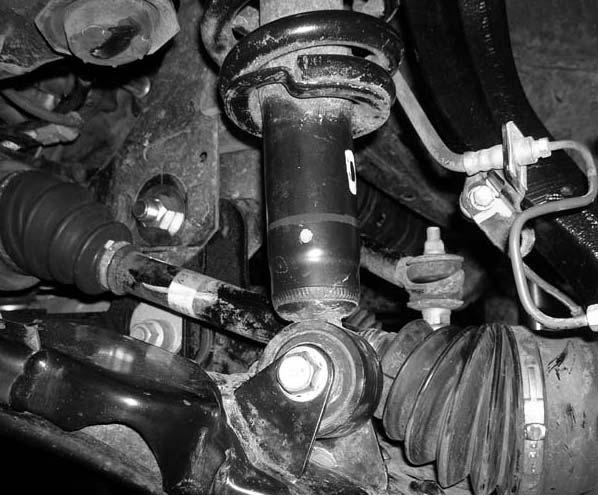
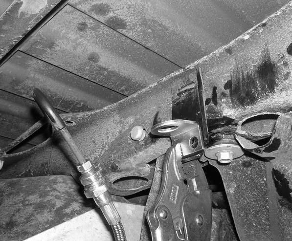
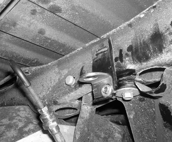
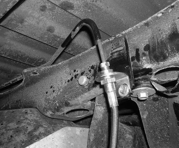
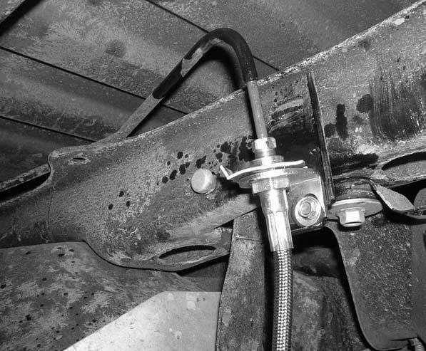
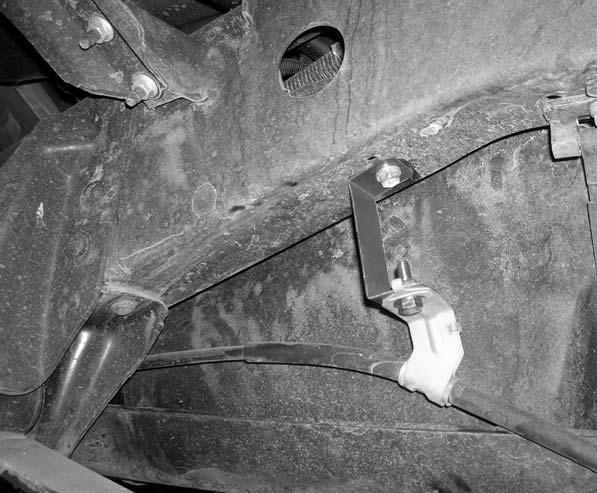
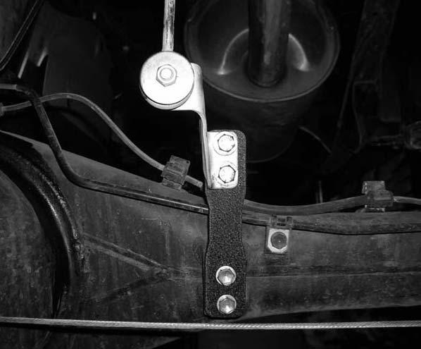
12 out the stock skid plate on the lines that were scribed earlier in this step. Photo # 121 Photo # Locate the stock skid plate hardware that was removed in step # 2. Install the stock skid plate into the stock location and secure using the stock hardware. Make sure to use thread locker or lock tite and torque to 18 ft lbs. Photo # Locate the stock rack and pinion outer ball joint cotter pin and nut that was removed in step # 6. Working on the driver side, install the stock rack and pinion outer ball joint to the stock lower ball joint plate and secure using the stock nut. Torque to 75 ft lbs. Making sure that the holes in the stock castle nut and the stock rack and pinion outer ball joint lined up, install the stock cotter pin. Special note: If the stock cotter pin can not be installed because the hole in the stock castle nut does not line up with the stock rack and pinion ball joint, DO NOT loosen the stock castle nut so that the cotter pin can fit, tighten the stock castle nut some more so that the stock cotter pin can be installed. Repeat procedure on the passenger side. Photo # Install the tires and wheels and carefully lower the vehicle to the ground With the weight of the vehicle on the ground, working on the driver side, torque the stock cam bolts that attach the stock front lower control arm to the newly installed one piece lower sub frame to 96 ft lbs. Repeat procedure on the passenger side Check and double check to make sure that all steps were performed properly. And then check them again. Front End Installation Complete: Rear End Installation: 108. To begin installation, block the front tires of the vehicle so that the vehicle is stable and can t roll forward. Safely lift the rear of the vehicle and support the frame with a pair of jack stands. Place a jack stand on both the driver and passenger side. Next, remove the rear wheels and tires from both sides Using a pair of hydraulic floor jacks, place one hydraulic floor jack on the driver side of the rear axle and one on the passenger side Working on the driver side, remove the stock shock from the stock upper and lower location. The stock shock and the stock upper hardware may be discarded. Save the stock lower hardware for later re-installation. Special Note: New longer rear shocks are needed, if you have not already ordered your new rear shocks, please contact Tuff Country or your local Tuff Country dealer and order the proper shocks. Tuff Country recommends using a 26 fully extended nitrogen gas shock. Repeat procedure on passenger side Working on the passenger side of the rear axle, remove the stock brake proportioning valve bracket from the stock location and save the stock hardware for later re-installation. Photo # Working on the driver side, remove the stock emergency brake cable bracket from the bottom of the stock frame rail. Save the stock hardware for later re-installation. Photo # Locate the new rear brake line. Remove the stock rear brake line from the stock upper and lower location. The stock upper brake line clip and the stock brake line may be discarded. Special note: Brake fluid will drain out, so place something under the vehicle to catch the fluid as it drains out. For now, install the new brake line to the stock upper and lower location and just hand tighten. This will help eliminate some brake fluid from draining out With a hammer, carefully hit the stock upper brake line bracket that is attached to the stock rear cross member. Hit with a hammer until the bracket is pointing directly down. Photo # 127 Photo # Locate (1) new S10137, rear brake line bracket, from hardware bag 55907NB1. Using a pair of vise grips, clamp the new brake line bracket to the stock brake line bracket. Photo # Locate (1) new S10138, 1/4 x 3/4 self tapping screw from hardware bag 55907NB1. Using a 1/8 drill bit and using the new brake line bracket as a guide, carefully drill a 1/8 hole into the stock brake line bracket. Now install the new 1/4 x 3/4 self tapping screw to secure the new brake line bracket to the stock brake line bracket. Remove the pair of vise grips. Photo # Remove the new brake line from the stock hard mount and install the new brake line and hard mount back together at the new brake line bracket. Torque to 26 ft lbs. Now torque to bottom mount of the new brake line to the stock bottom mount to 26 ft lbs. Photo # Locate (1) new e-clip from hardware bag 55907NB1. Install the new e-clip into the stock location. Photo # Working on the driver side, remove the stock u-bolts
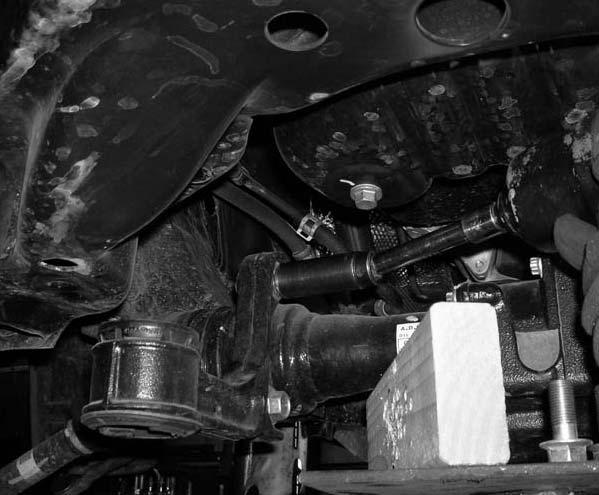
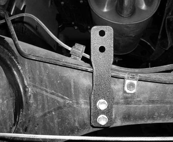
13 from the stock location and discard the stock u-bolts and u-bolt hardware. Set the stock upper bump stop and lower u-bolt plate aside for later re-installation. Repeat procedure on the passenger side Carefully lower down on both hydraulic floor jacks at the same time approximately 4.5. Take special care not to kink on over extend any brake lines and/or hoses Locate (2) new 4 lifted blocks. Working on the driver side, install the new 4 lifted block between the stock spring assembly and the stock axle. Special note: The new 4 lifted block has a slight taper to it, make sure that when you install the new block that you install it with the taper going towards the front of the vehicle. Repeat procedure on the passenger side Carefully raise up on both hydraulic floor jacks at the same time until the new 4 lifted rear blocks seat properly to the stock rear springs Locate (4) 9/16 x 2 9/16 x 10 5/8 square u-bolts. Locate the (8) new 9/16 u-bolt high nuts and (8) new u-bolt harden washers from hardware bag 916NW. Also, locate the stock upper bump stops and the stock lower u-bolt plates that removed in step # 119. Working on the driver side, install the stock upper bump stop, lower u-bolt plate and the new u-bolts into the stock location and secure using the new high nuts and harden u-bolt washers. Torque to 115 ft lbs. Repeat procedure on the passenger side. Photo # Carefully remove both hydraulic floor jacks from under the vehicle Locate (1) new rear brake proportioning valve bracket. Also, locate the stock rear brake proportioning valve bracket hardware that was removed in step # 111. Install the new rear brake proportioning valve bracket to the stock location using the stock hardware. Make sure to use thread locker or lock tite and torque to 12 ft lbs. Photo # Locate the stock emergency brake cable bracket hardware that was removed in step # 112. Also, locate (1) new BLR09 from hardware bag 55907NB1. Install the new BLR09 to the bottom side of the stock frame rail and secure using the stock hardware. Make sure to use thread locker or lock tite and torque to 12 ft. lbs Locate (1) 5/16 x 1 bolt, (2) 1/4 USS flat washers and (1) 5/16 unitorque nut from hardware bag 55907NB. Install the stock emergency brake line bracket to the newly installed BLR09 and secure using the new 5/16 x 1 bolt and hardware. Make sure to use thread locker or lock tite and torque to 18 ft. lbs. Photo # Locate (2) 5/16 x 1 bolts, (4) 1/4 flat washers and (2) 5/16 unitorque nuts from hardware bag 55907NB. Install the stock rear brake proportioning valve bracket to the newly installed rear brake proportioning valve bracket using the new 5/16 x 1 bolts and hardware. Special Note: Make sure to use thread locker or lock tite and torque to 18 ft lbs. Photo # Locate the new rear shocks. Special Note: New longer rear shocks are needed once this suspension system has been instead and the new rear shocks need to be ordered as a separate part #. If you have not already ordered your new rear shock, please contact Tuff Country or your local Tuff Country dealer and order your new rear shocks. Tuff Country recommends using a 26 fully extended nitrogen gas shock in the rear of your vehicle. Locate (4) new S10107 over size washers from hardware bag 55907NB. Also, locate (4) PB8297 front upper shock bushings from 55907NB1. Install the new bushings and proper sleeves into the lower eyelet of your new shocks. Special note: The new bushings and sleeves are supplied with your new shocks. Also, make sure to use a lithium or moly base grease prior to inserting the new bushings and sleeves into the new shocks. This will increase the life of the bushings and will help prevent squeaking. Install the new shock boots onto the new shocks. Special note: The new shock boots are not included with this suspension system and the new shock boots need to be ordered as a separate part #. If you have not already ordered your new shock boots, please feel free to contact Tuff Country or your local Tuff Country dealer and order your new shock boots. Install the S10107 over size washer and upper shock bushing onto the stud of the new shocks. Working on the driver side, install the new shock into the stock upper location, install the new upper shock bushing and new over size washer and secure the new shock into the stock upper location using the new nut. Special note: The new upper shock nut is supplied with your new shocks. Do not tighten at this point. Repeat procedure on the passenger side Locate the stock rear lower shock hardware that was removed in step # 110. Working on the driver side, install the new shock into the stock lower location using the stock hardware. Torque the lower stock hardware to 65 ft lbs. and torque the stock upper nut to 18 ft lbs Re-install the tires and wheels and safely lower the vehicle to the ground With the new rear brake line being replaced, brake fluid drained out. Top of the brake fluid with the proper brake fluid and bleed the brakes. Refer to the owners manual for proper instruction on how to bleed the brake lines Check and double check to make sure that all steps were performed properly. And then check them again.
14 Congratulations, installation complete! Special note: After the completion of the installation, Tuff Country EZ-Ride Suspension recommends taking the vehicle to an alignment shop and having a proper front end alignment performed. Tuff Country EZ-Ride Suspension recommends that a complete re-torque is done on all bolts associated with this suspension system. It is the customers responsibility to make sure that a re-torque is performed on all hardware associated with this suspension system after the first 100 miles of installation. It is also the customers responsibility to do a complete re-torque after every 3000 miles or after every off road use. Neglect of following these steps could cause brackets to come loose and cause serious damage to the suspension system and to the vehicle. Tuff Country EZ-Ride Suspension packages (2) sets of instruction sheets with this box kit. (1) is for the installer and (1) is for the customer. The (1) for the customer has some post installation procedure literature and it is the installers responsibility to make sure that the customer receives a copy of the installation manual along with the literature. If you have any questions or concerns, please feel free to contact Tuff Country or your local Tuff Country dealer.


15 Photo # 1 Photo # 2 Photo # 3 Photo # 4 Photo # 5 Photo # 6


16 Photo # 7 Photo # 8 Photo # 9 Photo # 10 Photo # 11 Photo # 12


17 Photo # 13 Photo # 14 Photo # 15 Photo # 16 Photo # 17 Photo # 18


18 Photo # 19 Photo # 20 Photo # 21 Photo # 22 Photo # 23 Photo # 24


19 Photo # 25 Photo # 26 Photo # 27 Photo # 28 Photo # 29 Photo # 30


20 Photo # 31 Photo # 32 Photo # 33 Photo # 34 Photo # 35 Photo # 36


21 Photo # 37 Photo # 38 Photo # 39 Photo # 40 Photo # 41 Photo # 42


22 Photo # 43 Photo # 44 Photo # 45 Photo # 46 Photo # 47 Photo # 48


23 Photo # 49 Photo # 50 Photo # 51 Photo # 52 Photo # 53 Photo # 54


24 Photo # 55 Photo # 56 Photo # 57 Photo # 58 Photo # 59 Photo # 60


25 Photo # 61 Photo # 62 Photo # 63 Photo # 64 Photo # 65 Photo # 66


26 Photo # 67 Photo # 68 Photo # 69 Photo # 70 Photo # 71 Photo # 72


27 Photo # 73 Photo # 74 Photo # 75 Photo # 76 Photo # 77 Photo # 78


28 Photo # 79 Photo # 80 Photo # 81 Photo # 82 Photo # 83 Photo # 84


29 Photo # 85 Photo # 86 Photo # 87 Photo # 88 Photo # 89 Photo # 90


30 Photo # 91 Photo # 92 Photo # 93 Photo # 94 Photo # 95 Photo # 96


31 Photo # 97 Photo # 98 Photo # 99 Photo # 100 Photo # 101 Photo # 102


32 Photo # 103 Photo # 104 Photo # 105 Photo # 106 Photo # 107 Photo # 108


33 Photo # 109 Photo # 110 Photo # 111 Photo # 112 Photo # 113 Photo # 114


34 Photo # 115 Photo # 116 Photo # 117 Photo # 118 Photo # 119 Photo # 120


35 Photo # 121 Photo # 122 Photo # 123 Photo # 124 Photo # 125 Photo # 126


36 Photo # 127 Photo # 128 Photo # 129 Photo # 130 Photo # 131 Photo # 132

37 Photo # 133 Photo # 134 Photo # 135 Photo # 136

")


 DS differential")
 PS")
 DS")
 PS sway bar")
38 (1) Driver side knuckle (1) Passenger side knuckle (2) Front upper strut spacers TOYBRAKE-01 (1) Rear brake proportioning valve bracket TOYDSDIFF-01 (1) DS differential relocation bracket TOYPSDIFF-01 (1) PS differential relocation bracket TOYDSSWAY-01 (1) DS sway bar relocation bracket TOYPSSWAY-01 (1) PS sway bar relocation bracket

 Rack")


")
")
39 TOYSTEER-02 (1) Steering shaft extension bracket TOYRACK-01 (1) Rack and Pinion support bracket TOYSUB-01 (1) One piece lower sub frame (4) Bump stop relocation brackets BLR01 (2) Relocation brackets BLR09 (2) Relocation bracket TOYRACK-02 (1) Center rack and pinion bracket
INSTALLATION MANUAL TOYOTA TUNDRA 5 SUSPENSION SYSTEM PART # 55905
 PART NUMBER : 55905 1999 2003 TOYOTA TUNDRA 5 SUSPENSION SYSTEM PARTS LIST: Part # Description Qty. 55900-01 Driver Side Spindle 1 55900-02 Passenger Side Spindle 1 55905-03 Rear brake proportioning valve
INSTALLATION MANUAL TOYOTA TACOMA 5 SUSPENSION SYSTEM PART # 54900
 PART NUMBER : 54900 1996 2004 TOYOTA TACOMA 5 SUSPENSION SYSTEM PARTS LIST: Part # Description Qty. 55900-01 Driver Side Spindle 1 55900-02 Passenger Side Spindle 1 54900-01 Rear brake proportioning valve
Installation manual. Toyota Tundra 4WD & 2WD. 2.5 Suspension kit. Part # Part # Important customer information:
 Installation manual 2007-2016 Toyota Tundra 4WD & 2WD 2.5 Suspension kit Part # 53070 sj11082011rev.03 Part # 53070 2007-2016 Toyota Tundra 4WD & 2WD 2.5 Suspension kit Part # Description Qty. 53070-01
Installation manual 3 front / 2 rear suspension system FJ / Runner Part # sj110607rev.03
 Part #: 52000 2007-2014 Toyota FJ / 2003-2009 4Runner 3 front / 2 rear suspension system Parts list: Part # Description Qty. 52907-01 Pre load spacer 2 52907-02 Strut spacer 2 MO3531BK-01 Rear coil spring
Installation manual. 3.5 suspension system Chevy / GMC 2500HD / 3500HD With contact overloads Part # 13090
 Part # 13090 2011-2016 Chevy / GMC 2500HD / 3500HD With contact overloads 3.5 suspension system Part # Description Qty. 13085-01 DS & PS Upper control arm 2 13085-02 DS & PS Front upper shock bracket 2
Installation manual. 4.5 suspension system June 2007 Dodge Ram 2500 / Part # Part # Important customer information:
 Installation manual 4.5 suspension system 2003 - June 2007 Dodge Ram 2500 / 3500 Part # 34003 sj11407rev.03 Part # 34003 2003 - June 2007 Dodge Ram 2500 / 3500 4.5 suspension system Part # Description
Installation manual 3 suspension system Toyota Tacoma 4 x 4 & PreRunner Part # sj rev.03
 Part #: 52904 1995-2004 Toyota Tacoma 4 x 4 & PreRunner 3 suspension system Parts list: Part # Description Qty. 52904-01 Rear brake proportioning valve bracket 1 52907-02 Front pre load spacer 2 52904-03
Installation manual Toyota Tundra 4WD & 2WD - 2 front leveling kit Toyota Sequoia 4WD & 2WD - 2 front leveling kit Part # 52070
 Part # 52070 2007-2016 Toyota Tundra 4WD & 2WD 2008-2011 Toyota Sequoia 4WD & 2WD 2 front leveling kit Part # Description Qty. 52070-01 Front strut spacers 2 52070NB Hardware bag 1 52070INST Instruction
Installation manual. 4 suspension system Chevy or GMC WD. Part # Part # Important customer information:
 Installation manual 4 suspension system 2014-2018 Chevy or GMC 1500 4WD Part # 14059 sj09052013rev.01 Part # 14059 2014-2018 Chevy or GMC 1500 4WD 4 suspension system Part # Description Qty. 14056-01 Upper
Installation manual. 3 suspension system Toyota Tacoma. Part # Part # Important customer information: Toyota Tacoma
 Installation manual 3 suspension system 2005 2008 Toyota Tacoma Part # 52907 sj111607rev.02 Part # 52907 2005-2008 Toyota Tacoma 3 suspension system Part # Description Qty. 52907-01 Pre-load spacer 2 52907-02
Installation manual 2 Leveling kit GM x 4. Part # Part # Important customer information: GM x 4
 Installation manual 2 Leveling kit 2007-2008 GM 1500 4 x 4 Part # 12000 sj121007rev.02 Part # 12000 2007-2008 GM 1500 4 x 4 2 leveling system Parts list: Part # Description Qty. 12000-01 Front leveling
Installation manual. 3 suspension system Toyota Tacoma. 4x4 and 2WD PreRunner. Part # Part # Important customer information:
 Installation manual 3 suspension system 2005 2018 Toyota Tacoma 4x4 and 2WD PreRunner Part # 52907 sj11112011rev.05 Part # 52907 2005-2018 Toyota Tacoma 4x4 and 2WD PreRunner 3 suspension system Part #
Installation manual. 3 Suspension Kit Ram WD. Part # Part # Important customer information: 2013 Ram WD
 Installation manual 3 Suspension Kit 2013-2016 Ram 3500 4WD Part # 33118 sj10232013rev.01 Part # 33118 2013 Ram 3500 4WD 3 Suspension Kit Part # Description Qty. 33118-01 Front coil spring spacer 2 33118-02
INSTALLATION MANUAL 4 I.F.S. SUSPENSION CURR. CHEVY SUBURBAN / YUKON XL (WITH 5 LINK REAR END) PART # 14965
 PART # 14965") PART NUMBER : 14965 2000 CURR. SUBURBAN W/ REAR COIL SPRINGS 4 SUSPENSION SYSTEM WITH FRONT SPINDLES PARTS LIST: Part # Description Qty. C4I1SN-07 Passenger Side Differential Drop 1 C4I1SN-23 Driver Side
PART NUMBER : 14965 2000 CURR. SUBURBAN W/ REAR COIL SPRINGS 4 SUSPENSION SYSTEM WITH FRONT SPINDLES PARTS LIST: Part # Description Qty. C4I1SN-07 Passenger Side Differential Drop 1 C4I1SN-23 Driver Side
Installation manual Hummer H3 4 suspension system Part # Part # Important customer information Hummer H3 4 Suspension system
 Installation manual Hummer H3 4 suspension system 2006 Part # 14040 sj022807rev.03 Part # 14040 2006 Hummer H3 4 Suspension system Parts list: Part # Description Qty. 14040-01 DS knuckle 1 14040-02 PS
Installation manual. Strong 6 suspension system Chevy or GMC 2500HD. Part # Part # Chevy or GMC 2500HD
 Installation manual Strong 6 suspension system 2001 -- 2010 Chevy or GMC 2500HD Part # 16993 sj030707rev.01 Part # 16993 2001-2010 Chevy or GMC 2500HD Strong 6 suspension system Parts contained in Box
Installation manual. Rear ladder bars. Chevy/GMC 2500/3500 HD. Part # Part # Important customer information:
 Installation manual 2011-2018 Chevy/GMC 2500/3500 HD Part # 10892 sj07272011rev.01 Part # 10892 2011-2018 Chevy/GMC 2500/3500 HD Part # Description Qty. 10892-01 Rear ladder bar brackets 2 10892-02 Front
Installation manual. 1.5 front leveling kit. Nissan Titan. Part # Part # Important customer information: Nissan Titan
 Installation manual 1.5 front leveling kit 2004-2015 Nissan Titan Part # 52008 sj071408rev.01 Part # 52008 2004-2015 Nissan Titan 1.5 front leveling kit Part # Description Qty. 52008-01 Front strut spacers
Installation manual. Rear traction bars. Ram Ram Part # Part # Important customer information:
 Installation manual Rear traction bars Ram 2500 2003-2013 Ram 3500 2003-2012 Part # 30991 sj12062011rev.01 Part # 30991 2003-2013 Ram 2500, 2003-2012 Ram 3500 Rear traction bars Part # Description Qty.
Installation manual. 4 Suspension system GM Colorado / Canyon Part # Part # GM Colorado / Canyon 4 Suspension system
 Part # 14045 2004-2012 GM Colorado / Canyon 4 Suspension system Parts list: Part # Description Qty. 14045-01 Driver side knuckle 1 14045-02 Passenger side knuckle 1 14045-03 Front cross member 1 14045-04
Installation manual. Long arm upgrade kit of lift March 1999 Dodge Ram 1500, 2500 and Part # 30945
 Installation manual Long arm upgrade kit 2-4.5 of lift 1994 - March 1999 Dodge Ram 1500, 2500 and 3500 Part # 30945 sj02222012rev.01 Part # 30945 1994 - March of 1999 Dodge Ram 1500,2500 & 3500 Long arm
Installation manual Strong 6 suspension system Chevy or GMC 1500 Part # 16959
 Part # 16959 1999-2005 Chevy or GMC 1500 Strong 6 suspension system Parts contained in Box 1 of 3 Part # Description Qty. 16955-16 Front cross member 1 16955-17 Rear cross member 1 16955-18 6 integrating
Installation Manual. 3 suspension system Ford F150. Part # Part # Important customer information: Ford F150
 Installation Manual 3 suspension system 2015-2018 Ford F150 Part # 23030 SS08282015 Part # 23030 2015-2018 Ford F150 3 suspension system Part # Description Qty. 23000-01 Driver side upper control arm 1
Installation manual 6 suspension system Chevy or GMC 1500 Part # 16955
 Part # 16955 1999-2005 Chevy or GMC 1500 6 suspension system Parts contained in Box 1 of 3 Part # Description Qty. 16955-03 Sub frame 1 16955-10 Front lateral compression arms 2 81350 Rear add-a-leaf /
Installation manual. 2 front / 1 rear spacer kit Jeep Wrangler JK 2 & 4 door Part # 42005
 Part # 42005 2007-2015 Jeep Wrangler JK 2 & 4 door 2 front / 1 rear spacer kit Parts list: Part # Description Qty. 42005-01 Front coil spring spacers 2 42005-02 Rear coil spring spacers 2 42005INST Instruction
INSTALLATION MANUAL 4.5 I.F.S. SUSPENSION CURR. FORD F150 W/4.2 OR 4.6 LITER PART # 24940
 INSTALLATION MANUAL 4.5 I.F.S. SUSPENSION 1997- CURR. FORD F150 W/4.2 OR 4.6 LITER PART # 24940 SJ101402 PART NUMBER : 24940 1997 CURR. FORD F150 W/4.2 OR 4.6 LITER 4.5 SUSPENSION SYSTEM WITH FRONT SPINDLES
Installation manual. 2 Suspension System. Ford F150 4WD and 2WD. Part # Part # Ford F150 4WD and 2WD
 Installation manual 2 Suspension System 2009-2018 Ford F150 4WD and 2WD Part # 22929 sj12112013rev.03 Part # 22929 2009-2018 Ford F150 4WD and 2WD 2 Suspension System Part # Description Qty. 22909-01 Front
Installation manual 3 SUSPENSION SYSTEM Dodge Ram 2500/3500 OLD PART # D32B NEW PART # 33920
 Installation manual 3 SUSPENSION SYSTEM 1994 2002 Dodge Ram 2500/3500 OLD PART # D32B NEW PART # 33920 sj060506rev.02 Old part # D32B New part # 33920 Dodge Ram 2500/3500 3 suspension system Parts list:
Torque Settings INSTALLATION MANUAL 3 I.F.S. SUSPENSION TOYOTA TACOMA PART # 52904
 INSTALLATION MANUAL 3 I.F.S. SUSPENSION 1995-2002 TOYOTA TACOMA PART # 52904 SJ010702 PART NUMBER : 52904 1995-2002 TOYOTA TACOMA 3 SUSPENSION SYSTEM PARTS LIST: Part # Description Qty. TT212-02 Rear Brake
Installation manual. Strong 4 suspension system Chevy or GMC 1500 Part # 14959
 Part # 14959 1999-2005 Chevy or GMC 1500 Strong 4 suspension system Parts contained in Box 1 of 3 Part # Description Qty. 14955-39 Front cross member 1 14955-40 Rear cross member 1 14955-41 4 integrating
Installation manual. 4 suspension system Suburban & Tahoe 4WD Avalanche 4WD Part # 14058
 Part # 14058 2007-2013 1500 Suburban & Tahoe 4WD 2007-2012 1500 Avalanche 4WD 4 suspension system Part # Description Qty. 14056-01 Upper strut spacer 2 14056-02 Rear upper shock bracket 2 14056-03 Skid
Installation manual. Front leveling kit. Part # Part # Important customer information: Ram WD Ram WD
 Installation manual Front leveling kit 2014-2018 Ram 2500 4WD 2013-2018 Ram 3500 4WD Part # 32909 sj10182013rev.02 Part # 32909 2014-2018 Ram 2500 4WD 2013-2018 Ram 3500 4WD Front leveling kit Part # Description
Installation Manual Ram x4 4 Lift w/upper control arms. Part # Part # 34105
 Installation Manual 2009 2018 Ram 1500 4x4 4 Lift w/upper control arms Part # 34105 ss09172014 Part # 34105 2009-2018 Ram 1500 4x4 4 suspension system w/upper control arms Part # Description Qty. 34105-01
INSTALLATION MANUAL 6 I.F.S. SUSPENSION CURR. CHEVY HEAVY DUTY WD PART # / WITH OUT SHOCKS PART # / WITH SHOCKS
 INSTALLATION MANUAL 6 I.F.S. SUSPENSION 2001 - CURR. CHEVY HEAVY DUTY 2500 2WD PART # 16987 / WITH OUT SHOCKS PART # 16988 / WITH SHOCKS SJ031502 Tuff Country EZ-Ride Suspension highly recommends that
INSTALLATION MANUAL 4 I.F.S. SUSPENSION SYSTEM DOOR TAHOE / LUG PART # 14830
 INSTALLATION MANUAL 4 I.F.S. SUSPENSION SYSTEM 1992-1998 2 DOOR TAHOE / 1500 6 LUG PART # 14830 SJ100702 PART NUMBER : 14830 1992-1998 / 2 DOOR TAHOE / 1500 6 LUG 4 SUSPENSION SYSTEM WITH FRONT SPINDLES
Installation manual. 2.5 suspension system. (Except Mega-Cab) Part # Part # Important customer information:
 Part # Part # Important customer information:") Installation manual 2.5 suspension system 2009-2018 Dodge Ram 1500 4WD (Except Mega-Cab) Part # 32102 sj02272013rev.01 Part # 32102 2009-2018 Dodge Ram 1500 4WD (Except Mega-Cab) 2.5 Suspension System
Installation manual 2.5 suspension system 2009-2018 Dodge Ram 1500 4WD (Except Mega-Cab) Part # 32102 sj02272013rev.01 Part # 32102 2009-2018 Dodge Ram 1500 4WD (Except Mega-Cab) 2.5 Suspension System
Installation Manual. Upper Control Arms W/Uniball joint Toyota Tacoma 4wd & 2wd PreRunner. Part # Part # 50930
 Installation Manual Upper Control Arms W/Uniball joint 2005-2016 Toyota Tacoma 4wd & 2wd PreRunner Part # 50930 SS08182014 Part # 50930 Upper Control Arms W/Uniball joint 2005-2016 Toyota Tacoma 4wd &
Installation manual. 2 front leveling kit. (Except Mega-Cab) Part # Part # Important customer information:
 Part # Part # Important customer information:") Installation manual 2 front leveling kit 2014-2018 Dodge Ram 1500 4WD (Except Mega-Cab) Part # 32103 sj02252014rev.01 Part # 32103 2014-2018 Dodge Ram 1500 4WD (Except Mega-Cab) 2 front leveling kit Part
Installation manual 2 front leveling kit 2014-2018 Dodge Ram 1500 4WD (Except Mega-Cab) Part # 32103 sj02252014rev.01 Part # 32103 2014-2018 Dodge Ram 1500 4WD (Except Mega-Cab) 2 front leveling kit Part
Installation manual. 4 performance suspension system Ford F150 or Bronco New part # Old part # F4XRB
 Part # 24814 1981-1996 Ford F150 or Bronco 4 performance suspension system Part # Description Qty. F2XRB-01 DS extended radius arm 1 F2XRB-02 PS extended radius arm 1 F2XRB-03 DS extended radius arm relocation
Installation Manual Chevy 2500/3500HD 4x4 3.5 Lift w/ Uniball upper control arms. Part # SS
 Part # 13086 2011-2017 Chevy 2500/3500 HD 4x4 3.5 lift with Uniball upper control arms Part # Description Qty. 13086-01 DS & PS Upper control arm 2 13085-02 DS & PS upper shock bracket 2 13085-03 Limiting
Installation manual. 4 Suspension system. Chevy or GMC 3500 Heavy Duty Part # Part # : Chevy or GMC 3500 HD
 Installation manual 4 Suspension system Chevy or GMC 3500 Heavy Duty Part # 14990 sj052306rev.04 Part # : 14990 2001 2006 Chevy or GMC 3500 HD 4 Suspension system Parts contained in Box 1 of 2 Part # Description
Installation manual. 4 suspension system Ford F150 or Bronco. Part # Part # Important customer information:
 Installation manual 4 suspension system 1981-1996 Ford F150 or Bronco Part # 24810 sj121609rev.01 Part # 24810 1981-1996 Ford F150 or Bronco 4 suspension system Part # Description Qty. F401 Front axle
Installation manual 6 Suspension system Chevy or GMC 1500 Heavy Duty Part # 16958
 Part # 16958 2001 2005 Chevy or GMC 1500 Heavy Duty 6 Suspension system Parts contained in Box 1 of 3 Part # Description Qty. 16985-04 One piece lower sub frame 1 16985-12 Lateral compression arms 2 16985NB
Installation manual. 6 suspension system Chevy or GMC 3500HD. Part # Part # Chevy or GMC 3500 HD
 Installation manual 6 suspension system 2011-2016 Chevy or GMC 3500HD Part # 16090 sj09062011rev.01 Part # 16090 2011-2016 Chevy or GMC 3500 HD 6 suspension system Parts contained in Box 1 of 3 Part #
Installation manual. Replacement front sway bar end link Dodge Ram Dodge Ram 1500 Part # 30927
 Part # 30927 1998-2012 Dodge Ram 2500-3500 1998-2001 Dodge Ram 1500 Replacement front sway bar end link Part # Description Qty. 30927NB1 Hardware bag 1 30927NB2 Hardware bag 1 30927INST Instruction manual
INSTALLATION MANUAL 4 I.F.S. SUSPENSION SYSTEM CHEVY / GMC LUG PART # 14810
 INSTALLATION MANUAL 4 I.F.S. SUSPENSION SYSTEM 1988-1998 CHEVY / GMC 1500 6 LUG PART # 14810 Sj051904rev.03 PART NUMBER : 14810 1988-1998 CHEVY / GMC 1500 6 LUG 4 SUSPENSION SYSTEM WITH FRONT SPINDLES
Installation manual 4 suspension system Toyota Tacoma 4x4 and 2WD PreRunner W/Uni-ball Upper Control arms Part # 54910
 Part # 54910 2005-2018 Toyota Tacoma 4x4 and 2WD PreRunner 4 suspension system W/Uni-ball upper Arms Part # Description Qty. 52907-02 Strut pre-load spacer 2 54910-01 Upper strut spacer 2 54910-02 Driver
Installation manual. 6 suspension system Chevy or GMC Silverado 2500HD. Part # Part # Important customer information:
 Installation manual 6 suspension system 2001 -- 2010 Chevy or GMC Silverado 2500HD Part # 16985 sj03062012rev.05 Part # 16985 2001-2010 Chevy or GMC Silverado 2500HD 6 suspension system Parts contained
Installation manual. 4 Suspension system Ford Super Duty F250 / F350. Part # Part # 24975
 Installation manual 4 Suspension system 2005-2016 Ford Super Duty F250 / F350 Part # 24975 SS05272014 Part # 24975 2005-2016 Ford Super Duty F250 / F350 4 Suspension system Part # Description Qty. 24975-CL01
Installation manual. 4 suspension system Ford Ranger 4WD. Part # Part # Important customer information: Ford Ranger
 Installation manual 4 suspension system 1983-1997 Ford Ranger 4WD Part # 24860 sj05032011rev.01 Part # 24860 1983-1997 Ford Ranger 4 suspension system Part # Description Qty. R401 Front axle pivot relocation
Installation manual 4.5 Suspension system Dodge Ram 2500 / Old part # D52B New part # Old part # D52B New part # 35920
 Installation manual 4.5 Suspension system 1994 2002 Dodge Ram 2500 / 3500 Old part # D52B New part # 35920 Sj052206rev.03 Old part # D52B New part # 35920 Dodge Ram 2500 / 3500 4.5 Suspension system Parts
Installation manual 4.5 Suspension system Dodge Ram 1500
 Installation manual 4.5 Suspension system 1994 2001 Dodge Ram 1500 Part # 35910 / 35912K / 35913K jd021816rev.04 Part # 35910 / 35912K / 35913K Dodge Ram 1500 4.5 Suspension system Parts list: Part # Description
Installation manual 2 Front and 1 Rear Lift w/rear shock extension brackets
 Installation manual 2 Front and 1 Rear Lift w/rear shock extension brackets 2016 Nissan Titan XD Part # 52050 SS06072016 Part # 52050 2016 Nissan Titan XD 2 front and 1 rear lift w/rear shock extensions
INSTALLATION MANUAL 4 SUSPENSION SYSTEM CHEVY PICKUP 3/4 TON PART # 14720
 INSTALLATION MANUAL 4 SUSPENSION SYSTEM CHEVY PICKUP 3/4 TON 1973 1987 PART # 14720 SJ051402 PART NUMBER : 14720 1973 1987 CHEVY PICK UP 3/4 TON 4 SUSPENSION SYSTEM / WITH REAR BLOCKS PARTS LIST: Part
Torque Settings INSTALLATION MANUAL 3 SUSPENSION SYSTEM CHEVY PICKUP 3/4 TON PART # 13720
 INSTALLATION MANUAL 3 SUSPENSION SYSTEM CHEVY PICKUP 3/4 TON 1973 1987 PART # 13720 SJ050702 PART NUMBER : 13720 1973 1987 CHEVY PICK UP 3/4 TON 3 SUSPENSION SYSTEM / WITH REAR BLOCKS PARTS LIST: Part
Installation manual. 4 Suspension system Chevy or GMC 1500 PART # Part # Chevy or GMC 1500
 Installation manual 4 Suspension system 1999 2005 Chevy or GMC 1500 PART # 14955 sj012406rev.03 Part # 14955 1999 2005 Chevy or GMC 1500 4 Suspension system Parts contained in Box 1 of 3 Part # Description
Installation Manual. Uniball Upper Control Arm Kit Toyota Tacoma 4x Toyota 4Runner 4x Toyota Tundra 4x4 Part # 50965
 Part # 50965 Uniball upper control arm kit Part # Description Qty. 50965-01 Driver side upper control arm 1 50965-02 Passenger side upper control arm 1 50965-03 Driver side knuckle support bracket 1 50965-04
Torque Settings. 5/ ft lbs. 3/ ft lbs. 7/ ft lbs. 1/ ft lbs. 9/ ft lbs. 5/ ft lbs. 3/ ft lbs.
 INSTALLATION MANUAL 2 OR 4 FRONT AND REAR SPRING SUSPENSION SYSTEM CHEVY PICKUP & BLZR 1/2 3/4 TON 1969 1972 PART # 14611 SJ052802 PART NUMBER : 14611 1969 1972 CHEVY PICK UP & BLAZER 1/2 OR 3/4 TON 2
Torque Settings. 5/ ft lbs. 3/ ft lbs. 7/ ft lbs. 1/ ft lbs. 9/ ft lbs. 5/ ft lbs. 3/ ft lbs.
 INSTALLATION MANUAL 6 FRONT AND REAR SPRING SUSPENSION SYSTEM CHEVY PICKUP 3/4 TON 1973 1987 PART # 16721 SJ052102 PART NUMBER : 16721 1973 1987 CHEVY PICK UP 3/4 TON 6 SUSPENSION SYSTEM FRONT AND REAR
INSTALLATION MANUAL 6 FRONT AND REAR SPRING SUSPENSION SYSTEM CHEVY PICKUP & BLZR 1/2 3/4 TON PART #
 INSTALLATION MANUAL 6 FRONT AND REAR SPRING SUSPENSION SYSTEM CHEVY PICKUP & BLZR 1/2 3/4 TON 1969 1972 PART # 16611 SJ052102 PART NUMBER : 16611 1969 1972 CHEVY PICK UP & BLAZER 1/2 OR 3/4 TON 6 FRONT
Installation Manual. 3 suspension system Toyota Tacoma 4WD & 2WD prerunner. Part # Part # Important customer information:
 Installation Manual 3 suspension system 2005-2018 Toyota Tacoma 4WD & 2WD prerunner Part # 53908 SS03012017 Part # 53908 2007-2018 Toyota Tacoma 4WD & 2WD Prerunner 3 Suspension System (no strut disassembly)
Torque Settings. 5/ ft lbs. 3/ ft lbs. 7/ ft lbs. 1/ ft lbs. 9/ ft lbs. 5/ ft lbs. 3/ ft lbs.
 INSTALLATION MANUAL 2, 3 OR 4 FRONT AND REAR SPRING SUSPENSION SYSTEM CHEVY PICKUP & BLAZER 1/2 TON 1973 1987 PART # 14711 SJ052102 PART NUMBER : 14711 1973 1987 CHEVY PICK UP & BLAZER 1/2 TON 2, 3 OR
Installation manual. 4 extended radius arm suspension system Ford Ranger 4WD Ford Explorer 4WD Part # 24862
 Part # 24862 1983-1997 Ford Ranger 4WD 1991-1994 Ford Explorer 4WD 4 extended radius arm suspension system Part # Description Qty. R4XRB-01 DS extended radius arm 1 R4XRB-02 PS extended radius arm 1 R4XRB-03
INSTALLATION MANUAL 6 SUSPENSION SYSTEM PART # CHEVY/GMC BLZR/SUBURBAN 1/2 TON
 INSTALLATION MANUAL 6 SUSPENSION SYSTEM CHEVY/GMC BLZR/SUBURBAN 1/2 TON 1988 1991 PART # 16730 SJ051402 PART NUMBER : 16730 1988 1991 CHEVY/GMC BLAZER & SUBURBAN 1/2 TON 6 SUSPENSION SYSTEM WITH REAR BLOCKS
INSTALLATION MANUAL 6 I.F.S. SUSPENSION CHEVY OR GMC 1500 SILVERADO PART # 16955
 INSTALLATION MANUAL 6 I.F.S. SUSPENSION 1999-2003 CHEVY OR GMC 1500 SILVERADO PART # 16955 sj031203rev.01 PART NUMBER : 16955 1999 2003 CHEVY 1500 PICK UP 6 SUSPENSION SYSTEM WITH FRONT SPINDLES Part #
INSTALLATION MANUAL FRONT PROGRESSIVE ADD-A-LEAF LEVELING SYSTEM 1998 CURR FORD SUPER DUTY F250 - F350 OLD PART # F2358B NEW PART # 22958
 INSTALLATION MANUAL FRONT PROGRESSIVE ADD-A-LEAF LEVELING SYSTEM 1998 CURR FORD SUPER DUTY F250 - F350 OLD PART # F2358B NEW PART # 22958 SJ093002 OLD PART NUMBER : F2358B NEW PART NUMBER : 22958 1998
Installation manual. 4 Suspension system Ford Super Duty F250 / F350 Part # & 24997
 Installation manual 4 Suspension system 2017-2018 Ford Super Duty F250 / F350 Part # 24995 & 24997 SS01312018 Part # 24995 & 24997 ( gas & diesel engines ) 2017 Ford Super Duty F250 / F350 4 Suspension
Installation manual. 4 Suspension system Ford Super Duty F250 / F350. Part # & Part # & ( gas & diesel engines )
") Installation manual 4 Suspension system 2017-2018 Ford Super Duty F250 / F350 Part # 24987 & 24989 SS08292017 Part # 24987 & 24989 ( gas & diesel engines ) 2017-2018 Ford Super Duty F250 / F350 4 Suspension
Installation manual 4 Suspension system 2017-2018 Ford Super Duty F250 / F350 Part # 24987 & 24989 SS08292017 Part # 24987 & 24989 ( gas & diesel engines ) 2017-2018 Ford Super Duty F250 / F350 4 Suspension
Installation Manual Nissan Titan 4 Suspension Sytem W/upper control arms. Part # & Part # & installation.
 Installation Manual 2016-2018 Nissan Titan 4 Suspension Sytem W/upper control arms Part # 54055 & 54056 SS07182017 Part # 54055 & 54056 2016-2018 Nissan Titan 4 Suspenson System W/upper control arms. Part
Installation manual. 6 suspension system Toyota Tundra Part # Part # Toyota Tundra 6 suspension system
 Part # 56070 2007-2018 Toyota Tundra 6 suspension system Parts contained in Box 1 of 3 Part # Description Qty. 56070-03 Front cross member 1 56070-04 Rear cross member 1 56070-06 Rear lateral compression
Installation Manual 2019 Ram wd. 2 front leveling kit. Part # Part # Ram wd (will not fit Air ride models)
") Installation Manual 2019 Ram 1500 4wd 2 front leveling kit Part # 32105 SS09062018 Part # 32105 2019 Ram 1500 4wd (will not fit Air ride models) 2 front leveling kit Part # Description Qty. 32105-01 Aluminum
Installation Manual 2019 Ram 1500 4wd 2 front leveling kit Part # 32105 SS09062018 Part # 32105 2019 Ram 1500 4wd (will not fit Air ride models) 2 front leveling kit Part # Description Qty. 32105-01 Aluminum
Installation Manual Ram x4 4 Lift w/uniball upper control. Part # SS rev.01
 Part # 34106 2009-2018 Ram 1500 4x4 4 suspension system w/uniball upper control arms Part # Description Qty. 34106-01 Driver side upper control arm 1 34106-02 Passenger side upper control arm 1 34105-03
Installation Manual Ram x4 5 performance kit with radius. Part # 35125
 Part # 35125 2014-2018 Ram 3500 4x4 5 performance kit with radius arms Part # Description Qty. 35135-01 driver side radius arm 1 35135-02 passenger side radius arm 1 35130-03 driver side front coil spacer
Installation Manual Ram x4 5 Lift w/ radius arm drop brackets Part # 35120
 Part # 35120 2014-2018 Ram 3500 4x4 5 Lift w/ radius arm drop brackets Part # Description Qty. 35130-01 driver side radius arm bracket 1 35130-02 passenger side radius arm bracket 1 35130-03 driver side
Installation Manual Ram x4 5 Lift w/ radius arm drop brackets Part # 35130
 Part # 35130 2014-2018 Ram 2500 4x4 5 Lift w/ radius arm drop brackets Part # Description Qty. 35130-01 driver side radius arm bracket 1 35130-02 passenger side radius arm bracket 1 35130-03 driver side
Installation Manual Nissan Titan XD 4 Suspension Sytem W/upper control arms. Part # & Part # & installation.
 Installation Manual 2016-2018 Nissan Titan XD 4 Suspension Sytem W/upper control arms Part # 54050 & 54051 SS01102017 Part # 54050 & 54051 2016-2018 Nissan Titan XD 4 Suspenson System W/upper control arms.
Installation Manual 4 Suspension System Toyota 4Runner with Upper Control arms. Part # Important customer information: Part # 54916
 Installation Manual 4 Suspension System 2010 2018 Toyota 4Runner with Upper Control arms Part # 54916 SS01172017 Part # 54916 2010-2018 Toyota 4Runner 4 suspension system with upper control arms Part #
Installation Manual Jeep JL 4 door 4 Suspension Lift Kit. Part # Part # installation Jeep JL 4 Door 4 Suspenson Lift kit
 Installation Manual 2018 Jeep JL 4 door 4 Suspension Lift Kit Part # 44100 SS12122018 Part # 44100 2018 Jeep JL 4 Door 4 Suspenson Lift kit Part # Description Qty. 44100-01 Front upper control arm 2 44100-02
Installation Manual 4 Suspension System Toyota 4Runner with Uniball Upper Control arms. Part # Important customer information:
 Installation Manual 4 Suspension System 2010 2018 Toyota 4Runner with Uniball Upper Control arms Part # 54917 SS01252017 Part # 54917 2010-2018 Toyota 4Runner 4 suspension system with uniball upper control
6 BASIC CROSSMEMBER SUSPENSION SYSTEM WD F-150
 www.fabtechmotorsports.com INSTALLATION INSTRUCTIONS 6 BASIC CROSSMEMBER SUSPENSION SYSTEM 2004-2008 2WD F-150 Fabtech Motorsports 4331 Eucalyptus Ave. Chino, CA 91710 Tech Line 909-597-7800 Fax 909-597-7800
" CHEVY / GMC WD BASIC KIT
 84302 2007-2013 6" CHEVY / GMC 1500 4WD BASIC KIT 100% Bolt On 6 Spindle Kit Front Differential Is Dropped A Full 6 To Maintain Proper CV Axle Angles Impact Struts To Distribute Front Suspension Impact
TOYOTA FJ CRUISER 6 SUSPENSION KIT
 92177000 TOYOTA FJ CRUISER 6 SUSPENSION KIT Thank you for choosing Rough Country for your suspension needs. Rough Country recommends a certified technician installs this system. In addition to these instructions,
Installation Instructions FRONT SUSPENSION INSTRUCTIONS: 1) Disconnect the negative terminal on the battery.
 Disconnect the negative terminal on the battery.") 75004 75001-5 COPONENT BOX 1 1) Rear Cross Member 1) Front Cross Member 1) Left Strut Spacer 1) Right Strut Spacer 2) Sway Bar Drops 1) Left Compression Strut 1) Right Compression Strut 2) Tie rods T538
75004 75001-5 COPONENT BOX 1 1) Rear Cross Member 1) Front Cross Member 1) Left Strut Spacer 1) Right Strut Spacer 2) Sway Bar Drops 1) Left Compression Strut 1) Right Compression Strut 2) Tie rods T538
4331 EUCALYPTUS AVE. ~~ CHINO, CA Fax FORD F-250/350 SUPER DUTY 4 WHEEL DRIVE FTS
 4331 EUCALYPTUS AVE. ~~ CHINO, CA 91710 909-597-7800 Fax 909-597-7185 2000-2003 FORD F-250/350 SUPER DUTY 4 WHEEL DRIVE FTS421-1 5.5 & 8 LIFT BOX KIT PARTS LIST: 1 EA. TRACK ARM BRKT. FT423-100 1 EA. PITMAN
04-08 FORD F150 4 KIT
 9257700 04-08 FORD F50 4 KIT THANK YOU FOR CHOOSING ROUGH COUNTRY FOR YOUR SUSPENSION NEEDS. Rough Country recommends a certified technician install this system. In addition to these instructions, professional
Installation Instructions
 Installation Instructions 4 Basic Suspension System 1997-2006 JEEP TJ 4WD Fabtech Motorsports 4331 Eucalyptus Ave. Chino, CA 91710 Tech Line 909-597-7800 Fax 909-597-7185 Web www.fabtechmotorsports.com
DODGE DIESEL KIT DODGE DIESEL KIT
 69120 2009-2013 DODGE 2500 8 DIESEL KIT 2009-2012 DODGE 3500 8 DIESEL KIT Heavy Duty Long Arm Construction For Superior Ride Quality And Travel Lower Arms Constructed Of 1.75 DOM Tubing W/ Urethane Bushing
TOOL LIST: (NOT INCLUDED) FLOOR JACK AND JACK STANDS ASSORTED METRIC AND S.A.E SOCKETS, & ALLEN WRENCHES DIE GRINDER WITH CUTOFF WHEEL AND MIG WELDER
 FLOOR JACK AND JACK STANDS ASSORTED METRIC AND S.A.E SOCKETS, & ALLEN WRENCHES DIE GRINDER WITH CUTOFF WHEEL AND MIG WELDER") www.fabtechmotorsports.com 4331 EUCALYPTUS AVE. ~~ CHINO, CA 91710 909-597-7800 FAX 909-597-7185 1997-2003 FORD F150 2 WHEEL DRIVE FTS97150-11 FRONT LONG TRAVEL KIT PARTS LIST: 1 EA. (UCA) PASSENGER S
www.fabtechmotorsports.com 4331 EUCALYPTUS AVE. ~~ CHINO, CA 91710 909-597-7800 FAX 909-597-7185 1997-2003 FORD F150 2 WHEEL DRIVE FTS97150-11 FRONT LONG TRAVEL KIT PARTS LIST: 1 EA. (UCA) PASSENGER S
Installation Instructions
 Installation Instructions 4 Ultimate Suspension System 1997-2006 JEEP TJ 4WD Non-Rubicon Models Fabtech Motorsports 4331 Eucalyptus Ave. Chino, CA 91710 Tech Line 909-597-7800 Fax 909-597-7185 Web www.fabtechmotorsports.com
DODGE RADIUS ARM KIT FITS GAS OR DIESEL
 66866 2013-2014 DODGE 3500 8 RADIUS ARM KIT FITS GAS OR DIESEL 66866-4 Component Box 1 2) 8 Coil Spacers 1) 8 Left Radius Arm 1) 8 Right Radius Arm 1) Track Bar Drop Bracket 1) Left Sway Bar Drops 1) Right
Rhino Long Travel Spindle Kit Yamaha Rhino FTR10072
 4331 EUCALYPTUS AVE. ~~ CHINO, CA 91710 909-597-7800 Fax 909-597-7185 Rhino Long Travel Spindle Kit 2005-08 Yamaha Rhino FTR10072 PARTS LIST: QTY. Part # Description 1 FTS95061D Rhino Spindle Driver 1
4331 EUCALYPTUS AVE. CHINO, CA
 www.fabtechmotorsports.com 4331 EUCALYPTUS AVE. CHINO, CA. 91710 PHONE 909-597-7800 FAX 909-597-7185 2000-2001 DODGE RAM 1500 4 WHEEL DRIVE 1994-2001 DODGE RAM 2500 4 WHEEL DRIVE FTS3420 5 1/2 LIFT BOX
Cognito Motorsports, Inc. Upper Control Arm Kit for 2011-Present GM 8-Lug #UCAK100051
 Cognito Motorsports, Inc. Upper Control Arm Kit for 2011-Present GM 8-Lug #UCAK100051 Introduction - Installation requires a qualified mechanic. - Read instructions carefully and study the pictures (if
INSTALLATION INSTRUCTION 88094
 INSTALLATION INSTRUCTION 88094 FOR RANCHO SUSPENSION SYSTEM RS6594B 4WD & 2WD NISSAN TITAN READ ALL INSTRUCTIONS THOROUGHLY FROM START TO FINISH BEFORE BEGINNING INSTALLATION Rev D IMPORTANT NOTES! WARNING:
This suspension system was developed using a Maximum tire size of 33 X 12.5 with a 17 x 9 aftermarket wheel with 4 1/2-5 backspacing..
 92174700 Thank you for choosing Rough Country for your suspension needs. 2005-15 TACOMA 6 Kit Rough Country recommends a certified technician install this system. In addition to these instructions, professional
Rhino Long Travel Spindle Kit Loaded Yamaha Rhino FTR10074
 4331 EUCALYPTUS AVE. ~~ CHINO, CA 91710 909-597-7800 Fax 909-597-7185 Rhino Long Travel Spindle Kit Loaded 2005-08 Yamaha Rhino FTR10074 PARTS LIST: FTR10074 Rhino Spindles FT95232 Hdwr Sub-Assembly Kit
CHEVY / GMC 1500HD / 2500HD 2WD 8 LUG 7 BASIC KIT
 85101 2000-2010 CHEVY / GMC 1500HD / 2500HD 2WD 8 LUG 7 BASIC KIT C8510-4 MAIN BOX KIT W/ HARDWARE 1) FRONT X MEMBER 1) REAR X MEMBER 2) TORSION BAR DROPS 1) LEFT BUMP STOP 1) RIGHT BUMP STOP 2) SWAY BAR
04-08 FORD F150 6 KIT
 957600 THANK YOU FOR CHOOSING ROUGH COUNTRY FOR YOUR SUSPENSION NEEDS. 0-08 FORD F50 6 KIT Rough Country recommends a certified technician install this system. In addition to these instructions, professional
INSTALLATION INSTRUCTION Rev A
 INSTALLATION INSTRUCTION 88587 Rev A FOR RANCHO SUSPENSION SYSTEM RS6587B: 2009 DODGE RAM 1500 READ ALL INSTRUCTIONS THOROUGHLY FROM START TO FINISH BEFORE BEGINNING INSTALLATION IMPORTANT NOTES! WARNING:
SPECIAL TOOLS REQUIRED:
 INSTALLATION INSTRUCTIONS FOR 2010-15 TOYOTA 4RUNNER WITH XREAS SUSPENSION 3 SUSPENSION LIFT KIT PART NUMBER 432X WARNING!!! READ AND UNDERSTAND ALL INSTRUCTIONS BEFORE PROCEEDING. MAKE SURE THAT YOU HAVE