Oscilloscope Diagnostics. A PicoScope Guide. Oscilloscope Diagnostics A PicoScope Guide. PicoScope Training. PicoScope Training
|
|
|
- Roderick Welch
- 5 years ago
- Views:
Transcription

1 PicoScope Training Noise and vibration testing Step 1 in our 5 steps to success with PicoScope PicoScope Training Pressure testing with the WPS500X PicoScope Training Advanced scope diagnostics PicoScope Training Starting scope diagnostics Oscilloscope Diagnostics A PicoScope Guide Oscilloscope Diagnostics A PicoScope Guide 1
2 Foreword By Alan Tong, Founder and Managing Director, Pico Technology When I started designing and building Pico oscilloscopes over 25 years ago, I could not have imagined how technology within the automotive industry would develop. Today I am proud that Pico is at the forefront of diagnostics in this industry. We work closely with our ever-growing customer base of vehicle manufacturers. Whether we are continuously developing the product at our headquarters near Cambridge, UK, or in our USA office in Texas, we are committed to meeting vehicle manufacturers needs through advancements in technology. As such, PicoScope is no longer limited to just electrical systems, but can also test and diagnose pressure, noise, vibration and harshness issues like never before. It s this heritage that allows us to create products for the aftermarket that continually grow in capability and have become the benchmark for scope-based diagnostics. We hope that this guide will show how the power of PicoScope can help benefit businesses, as we demonstrate the ease and simplicity of our PicoScope 6 Automotive software. 5 steps to success This document (Oscilloscope Diagnostics, A PicoScope Guide) is step 1 in a 5 step training program that we have developed to guide those new to PicoScope along their journey of scope diagnostics, from the very beginning. As you progress through the training program, you will learn PicoScope from our Guided Tests through to our more advanced features and accessories. The Steps are designed to progress your learning at a steady rate, teaching PicoScope from the ground up. Completing our 5 Steps to Success training program will give you the confidence to master your PicoScope and diagnostic skills. You can read more about the 5 Steps program here:
3 Contents Contents The diagnostic journey...1 Finding and testing the root cause with PicoScope... 1 Connecting with PicoScope... 2 What can PicoScope do?...3 Oscilloscope diagnostics using PicoScope software...4 PicoDiagnostics... 4 Scope diagnostics is only for the experts right?...5 Guided Tests...6 Our Top 10 tests with PicoScope 6 Automotive...8 TEST 1: Relative compression / cranking... 9 TEST 2: Ignition Coil-On-Plug...10 TEST 3: Wiggle test...11 TEST 4: Injector current...12 TEST 5: Lambda (oxygen) sensor testing...13 TEST 6: ABS speed sensor...14 TEST 7: Cam and crank sync...15 TEST 8: Air Flow Meter (AFM) also known as MAF (Mass Air Flow sensor)...16 TEST 9: CAN High and CAN Low...17 TEST 10: WPS500X compression testing...18 Pressure testing with the WPS500X pressure transducer...19 PicoDiagnostics...20 Battery test Compression Test Cylinder Balance Propshaft Balancing NVH Noise, vibration, harshness and balancing Taking the step beyond Guided Tests...26 The Waveform Library Understanding waveforms Analyzing waveforms So is that all PicoScope can do? Online resources Choosing the right kit for you...33 Accessories...35 Pressure testing kits and accessories...37 NVH kits and accessories...39 PicoScope storage solutions...40


4 The diagnostic journey To understand how you ultimately get the very best out of oscilloscope diagnostics with your PicoScope, it is helpful to understand where PicoScope fits into the diagnostic process. Our aim is for PicoScope to help your workshop give your customers the very best diagnostic service. Let us start with an example: A customer arrives with an engine running issue. Just like all forms of mechanical diagnostics, the first step is to ask the customer about the problem. This is often (but not always) accompanied by a dashboard warning light. Your next port of call will generally be to attach a serial diagnostic tool to the vehicle. In our example, this gave the fault codes P1345 Cam/Crank Synchro fault and Camshaft Sensor Open Circuit. With a degree of knowledge, we might assume that the most likely cause of these codes would be a faulty camshaft sensor. The camshaft sensor was replaced, the fault code erased, and the vehicle returned to the owner. In this example, the customer returned the next day with the same fault. Finding and testing the root cause with PicoScope The above is a simplistic view, but let us consider a workshop that has invested in PicoScope and is using it as an everyday tool for diagnostics. In this case, following the fault code read-out from the serial diagnostic tool, it would be common practice to connect the PicoScope to the camshaft sensor to test it before it is removed. When you capture data with PicoScope, it stores data in the Waveform Buffer. This allows you to scroll through frames of data post-test and to review your waveform captures. Zooming in on the camshaft waveform, it soon became clear there was an intermittent fault. 1

5 Running the test again, while gently wiggling the wiring loom, it quickly became apparent that there was a wiring issue. Further inspection of the wiring revealed chafing between the camshaft sensor wires. This fix was quick and simple to resolve without replacing any components. Following the wiring repair, the test was repeated with PicoScope which showed a clear fix. The fault codes were erased and the vehicle was returned to the customer. The workshop was confident that the root cause had been found and fixed. The customer left the workshop, happy with a successful repair. With no fault recurrence, this professional diagnostic workshop ensured future business with their customer. This is of course just one example of where PicoScope fits in the diagnostic journey. As technicians, you will understand there are many tools at your disposal, including technical information, training, knowledge, serial diagnostic tools, gas analyzers, and of course PicoScope. It is your ability to use these together that will ensure you remain a successful workshop in the future. Armed with PicoScope and the knowledge that you are able to see, analyze and understand the electrical signals that vehicle components produce, you will be confident that you can discover the root cause of a problem. This, in turn, will enhance the reputation of your business as a professional diagnostic provider. Don t just take our word for it. More than twenty of the world s leading vehicle manufacturers already use PicoScope in their dealer diagnostics, and it s our heritage and commitment that makes PicoScope the scope of choice. Connecting with PicoScope When you first start your diagnostic journey with PicoScope, the idea of connecting to vehicle components and reading their signals can feel daunting. At Pico, we have spent over 20 years breaking down the myths about scope diagnostics and helping our customers become some of our industry s leading diagnostic experts. Taking the time to read this guide will give you the foundation for a much wider knowledge and understanding of vehicle systems and analysis, leading to a more reliable and professional diagnosis of your customers vehicles. 2


6 What can PicoScope do? With ever more complex diagnostic problems facing the diagnostic workshop, a tool to get to the real root of the problem has never been more valuable. Only with PicoScope do you have such a high level of help available as a firsttime user, as well as lightning-fast capture rates to cope with the most advanced modern-day vehicle signals. Pico Technology is unique within the automotive industry, both in the way we specialize in the manufacture of PCbased scopes for automotive use, and how we work with an ever increasing number of the world s leading vehicle manufacturers for dealer-level oscilloscope diagnostics. This experience ensures that PicoScope is ahead of the competition and in constant advancement to tackle the fast-paced developments within the automotive industry. Over the following pages, you will find a summary of PicoScope and what it can do. We hope this will help show you that, by investing in PicoScope, your business can become proficient in vehicle diagnostics and stay ahead of the competition. Remember, PicoScope can be used on a wide range of vehicles and equipment including cars, trucks, bikes, agricultural vehicles, boats, and more. When used with our range of accessories, PicoScope can also detect signals relating to vacuum, fuel and hydraulic pressures, noise, vibration and harshness. It is safe to use, with no risk to the vehicles or the equipment, thanks to our non-intrusive testing methods. Charging and starting Pressure sensors Sensors System tests Actuators Communication networks Ignition 3


7 Oscilloscope diagnostics using PicoScope software Pico Technology s advanced diagnostics software is always on hand to help you, no matter what your experience of capturing component waveforms is. At this point, it is worth reminding ourselves what a waveform is. Simply put, it shows how voltage levels change over a period of time: What makes the PicoScope so powerful is the ability to capture these waveforms. It turns the vehicle s electrical signals into a picture that you can see, measure, manipulate, and compare, to understand exactly what is going on within a vehicle s systems in real time. PicoDiagnostics Arguably PicoScope s best-kept secret is our PicoDiagnostics software. This ever-evolving software is downloaded for free alongside our PicoScope Automotive software. It not only gives you an accurate, powerful battery, starter and alternator tester but also includes tests for relative compression and cylinder balance. Note that the performance of these tests is limited by some modern vehicles smart charging systems. As your journey into more advanced vehicle diagnostics continues, the purchase of our NVH Diagnostics Kit opens up the possibility of detecting and analyzing issues with noise, vibration, and harshness. A single installation file for both PicoScope 6 Automotive and PicoDiagnostics is available to download for free from our website at There are no charges or annual fees for updates. Our software is constantly evolving, which increases its value long after the initial purchase. Enjoy Pico s free software updates and lifetime support for your PicoScope. We are always happy to help our customers, regardless of the age of the product. 4
, it is surprisingly intuitive and easy to use for a novice.")

8 Scope diagnostics is only for the experts right? vs. This perception could not be further from the truth. While PicoScope may be used by some of our industry s foremost experts (thanks to its outstanding performance and resolution), it is surprisingly intuitive and easy to use for a novice. Let us start at the beginning. You are probably already familiar with using a multimeter as a basic check, to make sure that a component is receiving a power and signal voltage. You will also know that the multimeter is relatively easy to connect to the component. A scope benefits from a better connection, but the process is much the same as connecting a multimeter. For our scope connection we usually use back-pinning probes or breakout leads. They give you a more secure connection, and are just as easy to use. Let us look at an example of connecting to a camshaft sensor. Locate the sensor you wish to test by using a combination of experience and technical data. For a camshaft sensor, we recommend that you use a back-pinning probe. When this connection is made it is simple to attach your PicoScope. The simplicity of the connection is where the similarity with a multimeter stops. Only with a PicoScope can you see such high levels of detail in your test results. More importantly, the waveform is much more valuable to you as a technician than a simple multimeter reading. For example, a multimeter measurement of 7.46 V is displayed. However, with the same connection, PicoScope displays a clear and concise waveform, showing a 12 V camshaft sensor switching off and on with a regular pattern. Granted, this example is one of the easiest components to both connect to and analyze, but with PicoScope, there really are an unlimited number of tests you can undertake. We even include an ever-increasing selection of Guided Tests in the PicoScope 6 Automotive software, to help you test the most common components. 5

9 Guided Tests The Automotive menu in PicoScope 6 Automotive provides immediate access to a growing library of more than 150 comprehensive Guided Tests, which cover a variety of component tests, including: Starting and Charging circuits Sensors Actuators Ignition Communication networks Systems tests Pressure sensors Motorcycle-specific 6
10 Guided Tests When you select a Guided Test in the Automotive menu a test sheet is opened containing among other things: The purpose of the test How we recommend you connect to the component The recommended settings and accessories An example waveform Notes about the waveform to help with your analysis How to reach a diagnosis based on the analysis Additionall information how the component works and its relationship to other components Accessories BNC test lead Red clip Black clip TA A /2000 A DC Current clamp PicoScope settings Channel A: ± 20 V DC Channel B: ±100 A DC Timebase: 200 ms/div Sample rate: 1 ms In addition, when you select the Guided Test, the PicoScope software also opens a data file which sets up the PicoScope to run the given test. This means that in your first days of using PicoScope you don t have to worry about setting up the software manually you are simply ready to start running your test. 7

11 Our Top 10 tests with PicoScope 6 Automotive If you are new to PicoScope, you may be wondering exactly how you can use it and what benefits it will have for your workshop. With this question in mind, we have created what we feel are the top ten uses for PicoScope, with help and feedback from our users. We have included a brief overview of each test, the benefits the test offers you, and most importantly, how to: Connect Run Read Connect to the vehicle Capture the waveform Analyze the captured waveform Remember: These tests are supported with guided instructions, technical information and a settings file built into the PicoScope Automotive software. Today, we have more than 150 Guided Tests, but they are by no means the limit of what PicoScope can be used to test for. 8

12 TEST 1: Relative compression / cranking Software PicoScope 6 Automotive Guided Test AT004 Checking Suspected compression issues Skill level Connect 2000 A Current Clamp fitted around the battery+ cable. Make sure that the orientation of the clamp is correct with respect to the current flow away from the battery. Run Timebase should be set to 200 ms per division. Start PicoScope. Starter motor Read The waveform shows the amperage to crank the engine, usually between 80 and 200 amps. Once the engine has overcome the initial friction and inertia, the waveform should settle down to a consistent sawtooth pattern zoom and rulers can help evaluate here, although a drop in cylinder compression is often quite obvious. If the waveform confirms a cylinder is losing compression, further testing with a low amp current clamp, connected to an injector or ignition coil, will help to identify the offending cylinder. Using our WPS500X pressure transducer will highlight any mechanical issues requiring further attention. Each peak of the sawtooth pattern should be equal and level (once settled). 9


13 TEST 2: Ignition Coil-On-Plug Software PicoScope 6 Automotive Guided Test AT077 Checking Vehicle Single Coil Packs Skill level Connect Locate the top of your coil packs. Connect the Coil-On-Plug and Signal Probe to the PicoScope and earth to the vehicle. Run The engine must be idling for this test. Start PicoScope and place the end of the COP probe on the top of the coil pack to capture the signal. You should see a clear signal. Read The waveform will look something like the example below. Now you can see every detail. In our example, you can clearly see the burn time from the spark plug. It also shows the coil oscillation period. Remember how easy it is to use rulers to measure the different parts of the waveform, and our reference waveforms, to compare with different coil packs. Move the probe around to pick up the best signal. 10
 can reveal a wiring fault.")

14 TEST 3: Wiggle test Software PicoScope 6 Automotive Checking Wiring loom or connection faults Skill level PicoScope captures data so fast it is easy to identify wiring or connection issues quickly. Simply wiggling a wire (arguably an easy test that can often be overlooked) can reveal a wiring fault. Ignition switch Battery + Connect This test is used when you suspect or have spotted an intermittent fault with a signal (so a connection is already made). Run Start PicoScope when you are ready to capture the signal and gently wiggle the wiring loom attached to the component. We recommend reducing the capture rate to make it easier to spot problems within a single screen capture. Masks and alarms can be used to automate detection when signals go outside normal limits. Ignition relay Wiggle test Ignition coil Trigger PCM Read Stop PicoScope and scroll back through the data with the buffer controls. Often wiring or connection faults will create an inconsistent pattern as illustrated in the example. When we scrolled back through our captured data, it was easy to spot the signal faults from the ignition coil. In this example, it turned out that a fault in the wiring loom was causing an ignition misfire. Remember to retest after the repair, to make sure that you have a reliable fix. Fault identified by wiggle test Use a slow timebase across the screen while you do a wiggle test. 11

15 TEST 4: Injector current Software PicoScope 6 Automotive Guided Test AT039 Checking Injectors Skill level ECM Connect a 20 A / 60 A current clamp to Channel A on your PicoScope and place the clamp around the fuel injector supply wire. Note the orientation on the clamp. It may be necessary to pull back some of the loom s outer shielding to fit the current clamp. Run The engine must be running to perform this test. Click the Go button or press the space bar to capture the waveform. Read Under certain engine conditions you may find that each injection event is visible and includes: pilot, pre-, main and post injection. This can confirm the fuelling strategy under all test conditions. You can create a reference waveform to quickly compare multiple injectors on the screen. Applies to LPG, diesel, and petrol vehicles. Note: This is a multi point voltage waveform from a petrol injector. 12


16 TEST 5: Lambda (oxygen) sensor testing Software PicoScope 6 Automotive Guided Test AT022 & AT023 Checking Lambda (Oxygen) Sensor Skill level Remember to have a good earth point for this sensor. Connect Locate the sensor with the help of your vehicle s technical data. We recommend you use either back-pinning probes or breakout leads to make the connection. Use the technical data to identify the output signal wire from the lambda sensor harness connector. Run Note: The engine is required to be at the normal operating temperature in order to produce a valid signal. Start PicoScope when you are ready to capture the signal. Read Depending on the type of lambda sensor, the signal will be seen to cycle high and low in a consistent manner with curved edges. These sensors generally switch high and low once per second. We have included Guided Tests for measuring different types of lambda sensors, so please read these for further information. 13


17 TEST 6: ABS speed sensor Software PicoScope 6 Automotive Guided Test AT072 Checking Wheel speed sensor signal integrity Skill level Power supply Signal Connect Locate the wheel speed sensor signal wire. Use the vehicle s technical data. Where possible, we recommend you measure the wheel speed signal at the ABS control unit using back-pinning probes. Connect the coloured test lead to the wheel speed signal wire and the black test lead to vehicle ground. In cases where the ABS control unit is not accessible, the breakout leads will allow for connection directly to the ABS sensor or sensor fly lead Run Start PicoScope and rotate the relevant road wheel in order to obtain a speed signal. (There will be no speed signal when the road wheel is stationary.) ABS sensor (Hall effect) ABS pick-up Read As the wheel rotates, a stable and consistent waveform will be displayed by PicoScope. The frequency of the captured waveform will change in relation to the speed of wheel rotation (the frequency will increase as wheel speed increases and vice versa). Inspect the waveform for uniformity across one complete revolution of the road wheel. The wheel speed signal should remain stable and uniform throughout each revolution of the wheel at a fixed speed. PicoScope will reveal anomalies such as poor signal formation, reduced amplitude and sequential changes to each pulse that could reveal ABS pick-up damage. The waveform from a digital ABS speed sensor displays a square wave. 14


18 TEST 7: Cam and crank sync Software PicoScope 6 Automotive Guided Test AT151 Checking Synchronization between cam and crank Skill level Signal Crankshaft Signal Camshaft Connect Locate sensors using your vehicle s technical data. We recommend you use either back-pinning probes or breakout leads to make the connection. Use technical data to identify the signal wires. Run The engine must be idling to complete this test. Start PicoScope when you are ready to capture the signal. Read There should be a consistent pattern that develops as you capture data throughout 720 of crankshaft rotation. With cam and crank signals, this consistent pattern can provide invaluable data for waveform comparisons. Remember to extend the timebase to allow you to see multiple revolutions together. If each 360 camshaft revolution is consistent, it is likely that the synchronization between the camshaft and the crankshaft is correct, and that both sensors are working correctly. Inconsistencies will highlight probable valve timing issues, sensor faults or short circuits within the associated wiring looms. Use the rotation rulers to check the relationship between the crankshaft and camshaft sensors. 15


19 TEST 8: Air Flow Meter (AFM) also known as MAF (Mass Air Flow sensor) Software PicoScope 6 Automotive Guided Test AT008 & AT095 Checking Air Flow Meter testing Skill level Connect Locate sensors with the help of your vehicle s technical data. We recommend you use either back-pinning probes or breakout leads to make the connection. Use the technical data to identify the signal wire. You can choose to check multiple terminals to obtain a signal. Run Start PicoScope, and snap the throttle quickly from idle to full throttle to capture the waveform. We suggest a timebase of 1 s/div to capture 10 seconds of data in one frame. Power Air flow sensor PCM Read The voltage output from the air flow sensor should be proportional to air flow. The waveform should show approximately 0.5 volt when the engine is at idle, but this voltage will rise as the engine is accelerated, to around 4.0 to 4.5 volts. This voltage will, however, depend on how hard the engine is accelerated, and a lower voltage is not necessarily a fault within the air flow sensor. On deceleration the voltage will initially fall as the throttle is closed, reducing the air flow as the engine returns to idle speed. Further details are covered in our Guided Tests. The example waveform is from a gasoline airflow sensor. A diesel sensor waveform will look different. 16

. Connect the red lead to Channel B of the scope and to pin 14.")
20 TEST 9: CAN High and CAN Low Software PicoScope 6 Automotive Guided Test AT126 Checking Dual-trace testing CAN High and CAN Low Skill level Connect We recommend using our CAN Test Breakout box to make a secure connection to the vehicle s communication signals. When it is connected to the vehicle s diagnostic socket, the LEDs on the breakout box will light up to indicate that there is activity on the bus. Connect the yellow lead to Channel A of the scope and to pin 6, then the black pin to pin 4 (Chassis GND). Connect the red lead to Channel B of the scope and to pin 14. Note: Some vehicles can have multiple CAN connections on the 16-pin connector, and some vehicles may use pin 5 (Signal GND) instead of pin 4. Run Start PicoScope and turn on the vehicle ignition. You should now see a waveform. Read The waveform should reveal to you that data is being exchanged continuously along the CAN bus. It is also possible, of course, to check that the peak voltages are correct. The signals should be mirror images of each other, and there should always be two signals present. 17


21 TEST 10: WPS500X compression testing Software PicoScope 6 Automotive Guided Test AT157 Checking Petrol engine compression (advanced) Skill level Connect the WPS500X Pressure Transducer to PicoScope with the BNC to BNC test leads provided. Attach the transducer, as you would any compression gauge, by removing a spark plug and properly disabling the fuel system (if possible) and ignition for that cylinder. Run Start PicoScope and the engine. You may need to adjust the timebase and voltage scales to achieve the best signal display. Read Once you have captured your waveform you will be able to see everything that is taking place in every 720 cycle of the engine. To help you understand what you are seeing, use the rotation rulers (found in the bottom right-hand section of your PicoScope screen). You can adjust these markers to show 4 partitions, dividing the waveform into 180 sections and revealing the 4-stroke cycle. Now, with every stroke of the engine you can see exactly how the cylinder under test is operating: TDC > Ex Valve Opening > Exhaust Valve Closing > Inlet Valve Opening > Inlet Valve Closing > BDC. Switching the pressure transducer from one cylinder to the next is an easy way to have a direct and valuable comparison. TDC compression (maximum 8 bar) Exhaust valve open Exhaust valve closed Exhaust Expansion pocket Intake valve open Intake Intake pocket Intake valve closed Exhaust back-pressure (Partially blocked at 565 mbar) Atmospheric pressure (0 bar) Maximum negative pressure (vacuum -700 mbar) The Expansion pocket should have the same depth as the Intake pocket. Anomalies in this aspect indicate errors with valve timing or valve seat. 18
.")


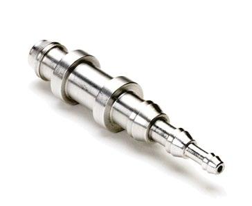
22 Pressure testing with the WPS500X pressure transducer Our WPS500X pressure transducer is the essential add-on to your PicoScope kit, allowing you to accurately view vacuum and pressure levels up to 500 psi (34.5 bar). The ability to display pressure, alongside electrical component signals in real time, gives you an unparalleled view into engine and vehicle diagnostics. Below is just one example of our WPS500X in use. With three different pressure ranges the WPS500X is optimized for measuring a vast array of vehicle pressures ranging from cylinder compression to positive and negative fuel line pressures and exhaust gas pulsations at the tailpipe (in relation to combustion). Nothing shows engine compression like our pressure transducer see it all with the WPS500X. Expansion pocket. Intake and exhaust valves closed. Exhaust stroke. Intake valve closed, exhaust valve open. Intake stroke. Intake valve open, exhaust valve closed. Compression stroke. Intake and exhaust valves closed. 19

23 PicoDiagnostics When you download the PicoScope software you also get a free companion program, PicoDiagnostics. PicoDiagnostics is the fault-finding software for your PicoScope oscilloscope. The PicoDiagnostics program includes a range of built-in tests that are quick and easy to operate. These built-in tests cover testing of batteries, alternators, starter motors, compression and cylinder balance. The ability to print professional reports also allows you to show your customer that you have performed a rapid health check. Our software really does turn your PC into an automotive diagnostics tool. PicoDiagnostics supports the PicoScope 3000 Automotive and 4000 Automotive diagnostic scopes. 20


24 Battery test This feature tests the starting and charging system on the vehicle and is used by both vehicle manufacturers and independent workshops. At Pico Technology we know that charging and starting systems are at the very heart of modern vehicles electronics. We understand how important they are in making sure that all components function at their very best. With this in mind, we developed this vehicle health check, as a primary test for every vehicle that enters the workshop. By doing this test you can certify that the vehicles function perfectly, giving your customers peace of mind and generating valuable business. For every Battery Test done you get a report that can be fully customized with your workshop details and logo. You can print this and give it to your customer, both before and after work is undertaken. Starter motor Alternator 21


25 Compression Test The compression test is meant to be the first check. If the compression looks good you can quickly move on and investigate other components which might be the cause of the fault. If the test detects a low cylinder, you should perform a manual compression test to verify the results and to detect which cylinder is low. Note: Two different types of compression test are supported by PicoDiagnostics: relative compression and absolute compression. You must, however, use a WPS500X to be able to perform an absolute compression test. Cylinder Balance The cylinder balance test measures how much each cylinder contributes to the engine s total power output. A number of issues can cause a cylinder to contribute less than the other cylinders, including, but not limited to: low compression faulty injector faulty spark plug 22


26 Propshaft Balancing The propshaft needs to be balanced after the removal of one or more component of the transmission system. The propshaft balancing program can help you with your on vehicle balancing. You can fit balancing weights on the differential coupling flange, use off-the-shelf hose clamps on the propshaft or attach a single balancing weight to the propshaft. The program displays step-by-step instructions in the form of a Wizard for both formats of this test. We recommend that you follow your chosen procedure carefully. Don t forget, you can also save or print a report of this work to give to your customer or to keep for your records. The Propshaft balancing program can be used to rectify a propshaft imbalance that may be detected during NVH testing (see next page). 23

27 NVH Noise, vibration, harshness and balancing The PicoDiagnostic NVH kit enables the identification and diagnosis of unwanted vehicle vibration and noise sources. The kit is the cost-effective answer to the many NVH problems technicians are facing today. It provides real-time analysis in the form of either: a bar graph, a frequency chart, a 3D frequency chart, RPM order, time domain or road speed view. The ability to start the recording before a road test, and play back the recording for analysis upon return to the workshop, lets the driver focus on the driving during the road test. Our NVH kit works with the PicoScope 4000 Series Automotive oscilloscopes, and it is available in a number of configurations to suit your needs Hz Vibration only Hz Vibration and noise 200 Hz-20 khz Noise only The root of all NVH problems is vibration. In some cases, these are abnormal vibrations and in other cases, they are always present (e.g. engine combustion). They should, however, never reach the driver or the passengers. Noise is vibration transmitted through the air and is heard when it reaches a person s ear. The perfect hearing range is 20 Hz to 20 khz, and vibrations are usually felt at frequencies below 200 Hz; in the overlapping frequency range, vibrations can both be felt and heard. In order to deal with this frequency range effectively, the PicoDiagnostics NVH kits contain microphones (for sound) and accelerometers (for vibration). Traditionally, NVH problems have been viewed as being both difficult to solve and subjective, as people have different levels of sensitivity. For technicians to tackle these issues effectively, they require the right tools and procedures to diagnose objectively and simply. 24


28 Typical uses Customer complaints surrounding noise and vibration are subjective and present technicians with a challenge before diagnosis and rectification begin. You can use the NVH kit on the vehicle and road-test it with the customer to obtain all vibration and noise levels. When this valuable data has been collected, it can be analyzed and compared to previous captures or other vehicles. A problem vibration is, in many cases, a characteristic. With the collected data you can present and compare with previous captures or donor vehicles, and can confidently assure your customer that everything is as it should be. Alternately, the data comparison could highlight a problem, giving the technician the necessary information to repair the vehicle with confidence. Below are just a few typical scenarios where the NVH kit can save you time and money: Cabin vibrations at speed Engine vibrations throughout the entire RPM range Clutch judder or vibration Transmission and bearing whine Auxiliary driving noise Brake judder Steering vibrations 25

29 Taking the step beyond Guided Tests The many Guided Tests included in the PicoScope Automotive software are invaluable when you first start using your PicoScope. Inevitably there will come a point where you want to test a component or system using your own settings. This does not have to be as difficult or daunting as you may think, as it is highly likely that the test you want to undertake already has been done by one of our team or other customers. First, search the Waveform Library for the component you wish to test. When you find the waveform, you simply open it. When you open up a PicoScope waveform, the software automatically adjusts the timebase and voltage scale to the parameters set when the test was undertaken. At this point, you will have to use the technical data and, of course, your own knowledge base to find the component and connect to it. Remember you can also load a reference waveform to see on screen while you capture your own data. That way, you can make a post-capture comparison. 26

30 The Waveform Library The Waveform Library has thousands of waveforms you can use for both good and bad references. It lets you search for a valuable waveform you can then compare with your own test. When you have found a waveform, you can import the full captured waveform or individual channels. This makes it easy to compare with your own captured signal. Often rulers become very powerful when comparing. It is worth remembering that this powerful feature will allow you to save and share your own waveforms with the PicoScope community, and if you get stuck you can always or call our support team for further advice. You can find more help and advice at Our online forum is a great source of help and information, as well as the many case studies and online training articles we have published. You will also find a list of our recommended trainers and links to their various training courses so that you can increase your understanding and knowledge about using PicoScope even further. 27


31 Understanding waveforms The first things to consider when viewing and analyzing waveforms are the timebase and voltage scales. While our Guided Tests will set these up for you, it is a good idea to take the time to learn the basics. This will help you analyze waveforms and hone your PicoScope skills. Let us go back to the beginning and simply see the waveform as voltage shown over time, and apply this to what we see on the screen. Voltage The voltage is by default set to ±5 V, but can easily be changed. The menu is adjacent to each channel option button. You can click the Input range drop-down button and choose from a grid menu, or you can click the increase or decrease buttons to choose the next value on the respective side of the scale. Your chosen voltage scale is divided equally between the 10 vertical divisions shown on screen. In our example each division represents 1 V, from -5 V to +5 V. Timebase The timebase is by default set to 5 milliseconds per division (5 ms/div). There are ten divisions on the screen. A setting of 5 ms/ div gives you 50 ms of time across the entire capture. The settings for this are located on the toolbar. You can change the setting by clicking the Collection time drop-down button and chose from a grid menu, or you can click the increase or decrease buttons to choose the next value on the respective side of the scale. To view more detail of a single event, simply reduce the timebase. To view more events with less detail, simply increase the timebase. It is worth taking the time to become familiar with these settings, as they will let you make small changes to how the waveform is displayed on the screen. This can prove invaluable to you, as it enables you to see it in the detail you require. Do not forget that the Auto Setup button is there to help, and will adjust your capture settings to show you sensible waveforms. When you are connected to the component, and your settings are complete, you just press the Go button (or alternatively the spacebar on your keyboard). PicoScope will start to record the data. Stop the test at any time and scroll back through your waveforms with the waveform buffer: This is particularly useful for spotting intermittent faults. 28

32 Analyzing waveforms We have now covered a little about the screen and some basics about setting up and understanding the parameters. Next, let us take a look at how we best analyze and understand waveforms. Of course, there is no magic wand here, but PicoScope allows you to easily view waveforms in the very best way possible. Combine this with our Guided Tests and the Waveform Library (see below) and we provide you with some great tools to help understand and analyze what you see. The ability to interpret waveforms is still where the skill lies. We supply many reference waveforms, both within our Guided Tests and on the Waveform Library. It is, however, worth remembering that you are usually not looking for an exact match, but a way to compare and evaluate (as in our example) whether a component is working correctly. The Reference Waveform in the example above has been captured at a slightly different voltage scale to our test component. At first glance, it appears difficult to use as a comparison, but it is still valuable. We know that the green waveform signal has come from a good coil pack, and despite the blue waveform from our coil pack having been recorded at a different voltage scale, it is easy to see that there is no coil oscillation taking place; so we indeed have a faulty coil pack. We could adjust the scaling and offset of our signal to make visual comparison easier. 29


33 So is that all PicoScope can do? Simply put, no. This guide is written to help new users get started with PicoScope. As you become more proficient with using PicoScope you can start working with more of our advanced features. Filtering Fundamentally, unpowered sensors such as lambda have a high output resistance leaving both the sensor and wiring prone to the pick-up of noise. Inside the PCM the signal will be filtered but it is helpful to see both the unfiltered and filtered version as the comparison will help to reveal what is expected noise and what is affecting the signal as seen by the PCM. Coupling The default Coupling setting of DC allows the scope to display both the DC and AC aspects of the input signal. Selecting the AC coupling option we block the DC component of the input signal and allow only the AC to be displayed on the screen. An example of this coupling feature would be to apply it to a running car s battery, revealing the alternator ripple (see Channel A). Serial Decoding You can use PicoScope to decode data from a serial bus such as FlexRay or CAN Bus. Unlike a conventional bus analyzer, PicoScope lets you see the high-resolution electrical waveform at the same time as the data. The data is integrated into the scope view, so there s no need to learn a new screen layout. In the viewer, you have the ability to filter or search on specific messages, data or errors. 30


34 Math channels Clicking on Tools>Math Channels from your PicoScope screen will reveal numerous built-in math channels that will assist you when looking at the input signals. While these math channels will invert, add, subtract, divide, or multiply any combination of channels of interest, you are also able to create your own math channels within the software. Below, you can see an isolated math channel that reveals the result of Channel A minus B. Masks Mask limit testing is a feature that tells you when a waveform goes outside a specified area, called a mask, drawn on the screen. PicoScope can draw the mask automatically by tracing a captured waveform, or you can draw it manually. Mask limit testing is useful for spotting intermittent errors on both the timing and signal level. Alarms Alarms are actions that PicoScope can be programmed to execute when certain events occur. PicoScope can be left running and will automatically stop and save the waveforms to disk or trigger external actions when the buffers are full or a mask fail is detected. 31


35 Online resources In addition to free software updates, lifetime support, the already mentioned Waveform library and our Guided Tests there are many online resources available for guidance on our website: The Automotive Forum The forum is a great place to ask for advice, help other Pico users and find valuable information. When you register for an account on the forum, you also gain access to the Waveform library while you have your PicoScope connected. Videos We have many videos available with great content, both from Pico and from third parties. In addition to being posted on the website, you can also find them on our PicoScope Automotive channel on YouTube. Case studies We have a series of case studies where the automotive oscilloscope is used to diagnose vehicle faults. Fault-finding procedures and detailed explanations of components and systems makes it a mustread. Training We have our own training section as well, with an ever-growing collection of videos, articles and guides, as well as information about training courses. We are always happy to help at Pico, and if you need anything else you can reach our Technical Support team on the phone, via or on Skype. This is regardless of how old your Pico product is. You can also contact the Technical support team for training enquiries. Telephone: support@picoauto.com Skype: pico_tech_support 32
, right up to our 4-Channel advanced kit (offering a comprehensive range of")
 2 x BNC to 4 mm test leads (blue & red) 1 x 1.")
 1 x secondary ignition")

36 Choosing the right kit for you After establishing your need for a PicoScope, how do you choose the right kit? Below is a summary of our kits, ranging from starter kits (giving you a basic set of adaptors to get going with PicoScope), right up to our 4-Channel advanced kit (offering a comprehensive range of accessories within the kit). The kits are available in a carry case, foam trolley trays, or both. 2- and 4-channel starter kits 2-channel starter kit Order code: Box PP920 / Foam PQ000 2-channel PicoScope x Small crocodile clip (black & red) 2 x BNC to 4 mm test leads (blue & red) 1 x 1.8 m Pico USB3 Cable 2 x Battery Clip (black & red) 2 x Flexible back-pinning Probe (black & red) 1 x High bandwidth 10:1 attenuator 1 x PicoScope Software CD 1 x Pico Advanced Vehicle Diagnostics DVD 4-channel starter kit Order code: Box PP921 / Foam PQ001 4-channel PicoScope 4425 Same accessories as 2-channel starter kit, plus: 2 x additional test leads (green & yellow) 1 x secondary ignition pickup 1 x additional battery clip black 2 x additional flexible back-pinning Probe (black & red) 2 x additional small crocodile clip (black & red) 2- and 4-channel standard kits 2-channel standard kit Order code: Case PP922 / Foam PQ002 2-channel PicoScope 4225 Contains all the items in the 2-channel starter kit plus: 1 x 20 A / 60 A AC/DC current clamp 1 x 200 A /2000 A AC/DC current clamp 1 x COP and signal probe 1 x standard ATC fuse extension lead 1 x mini ATC fuse extension lead 2 x multimeter probe (black & red) 2 x shrouded to unshrouded adapter (black & red) 2 x secondary ignition pickup 1 x S-hook 1x back-pinning probe set 4-channel standard kit Order code: Case PP923 / Foam PQ003 4-channel PicoScope 4425 Same accessories as 2-channel standard kit, plus: 2 x additional small crocodile clips (black & red) 1 x additional high bandwidth 10:1 attenuator 2 x additional flexible back-pinning probes (black & red) 1 x additional battery clip black 2 x additional test leads (green & yellow) 33
 fuse extension lead 1 x 2-pin Kostal breakout lead 2 x S-hook 1 x 2-pin ACS breakout lead 1 x 200 A / 2000 A AC/DC current clamp 2 x multimeter probe (black) 1 x mini")

 1 x additional 20 A / 60 A DC current clamp 4 x HT extension leads 1 x Premium")
37 4-channel diesel kit Order Code: Case PP924 / Foam PQ004 4-channel PicoScope 4425 Contains all the items in the 4-channel starter kit plus: 1 x 20 A/60 A AC/DC current clamp 1 x 2-pin AMP connector breakout lead 1 x Standard (ATC) fuse extension lead 1 x 2-pin Kostal breakout lead 2 x S-hook 1 x 2-pin ACS breakout lead 1 x 200 A / 2000 A AC/DC current clamp 2 x multimeter probe (black) 1 x mini ATC fuse extension lead 2 x multimeter probe (red) 2 x shrouded to unshrouded adapter (red) 1 x back-pinning probe set 2 x shrouded to unshrouded adapter (black) 1 x JCASE fuse extension lead 1 x 60 MHz oscilloscope probe x1/x10 1 x Maxi fuse extension lead 4-channel advanced kit Order Code: Case PP925 / Foam PQ005 4-channel PicoScope 4425 Contains all the items in the 4-channel standard kit plus: 1 x 60 MHz Oscilloscope Probe 2 x additional Secondary ignition pickup 1 x additional S-hook 2 x additional Multimeter probe (black & red) 2 x Dolphin clip (black & red) 1 x 2-pin AMP connector breakout lead 1 x 2-pin ATS connector breakout lead 2 x additional 4 mm shrouded to unshrouded adaptor (black & red) 1 x additional 20 A / 60 A DC current clamp 4 x HT extension leads 1 x Premium 6-way breakout lead set Master kit Order Code: Case PQ039 / Foam PQ040 4-channel PicoScope 4425 Contains all the items in the 4-channel advanced kit, plus: 1 x additional 60 MHz Oscilloscope Probe 1 x 4.5m USB 2.0 cable for PicoScope 2 x additional 4 mm shrouded to unshrouded adaptor (black) 2 x additional 4 mm shrouded to unshrouded adaptor (red) 1 x 2-pin AMP connector breakout lead 1 x 3-pin AMP superseal connector breakout lead 1 x 2-pin ACS connector breakout lead 1 x 3-pin Kostal connector breakout lead 1 x 2-pin Kostal connector breakout lead 2 x PicoScope sprung hook probe (black & red) 1 x 30 A current clamp (replaces 1 x 20 A/60 A current clamp) 1 x Maxi fuse extension lead 1 x GearTie assortment 8 pack 1 x CAN test box 1 x JCASE fuse extension lead 1 x Piercing clips set 34


38 Accessories Here is an overview of some of our accessories: what they are, what they do, and how they can enhance your diagnostic capabilities. For our full range of PicoScope kits, accessories, and current pricing, please visit: Current clamps 60 A / 20 A Order Code: TA A / 200 A Order Code: TA A Order Code: TA234 A Pico current clamp is an important addition to our starter kits, opening up current measurements of components and systems. From fuel pumps and injectors to ignition coils, being able to see the current provides a valuable insight into correct and faulty behaviour. Add extra clamps to your kit to capture multiple injectors at the same time. Connector breakout lead kit B Order Code: PQ030 Premium 6-way breakout lead kit Order Code: TA324 CAN test box Order Code: TA069 This range of common breakout leads makes component connections easy. They are the preferred method of connection for vehicle manufacturers and professional diagnostic experts, as their design allows for access to individual wires. Our Premium 6-way breakout lead kit contains 11 sets with 6 different sized universal breakout leads and one set with 6 back-pinning probes. Our CAN test box allows connection between your PicoScope and a vehicle s 16-pin OBD port. We recommend this method for obtaining your vehicle s CAN signals (see Guided Test AT126). The CAN Test Box terminals accept standard 4 mm plugs. 35


39 Coil-On-Plug and Signal probe Order Code: PP357 Secondary ignition pickup (capacitive with BNC) Order Code: MI074 HT Extension lead (set of 4 leads) Order Code: PP400 Add to Starter kits to pick up secondary ignition waveforms from most coil-on-plug or coil-per-cylinder systems. The MI074 is a capacitive pickup that connects around the insulation of an ignition circuit component (such as a plug wire), avoiding the need for direct connection. Use our MI074 in conjunction with our HT extension leads to read Multi COP signals. This set of breakout leads is ideal for Multi COP packs. Simply fit one lead between each coil pack and plug, place an MI074 secondary ignition pickup on each lead, and your scope will show accurate ignition waveforms with correct kv measurements. Back-pinning probes Order Code: TA008 Fuse extension leads kit Order Code: PP V Differential probe Order Code: TA057 The back-pinning probes slip down the side of the insulation on the back of multi-plug terminals, allowing you to pick up signals without stripping wires or disconnecting plugs. With spare pins and screws included, these are a must have for any diagnostic technician. Do you find it hard to break into particular vehicle circuits? With Pico s fuse extension leads, you can easily extend the fuse connection to allow space for a current clamp and measure the current draw for the circuit. Set includes ATC, mini- ATC, JCASE, and Maxi style fuse extensions. Add our 1400 V differential probe to any kit and it allows the measurement of much higher voltages, which is ideal for hybrid and electric vehicles. This probe has a bandwidth of 25 MHz, with differential voltage ranges of 1400 V, and is CAT III rated. 36


40 Pressure testing kits and accessories WPS500X Pressure Transducer Kit Order Code: PP939 The ultimate accessory to all of our PicoScope kits. View your vehicle s engine and vital components, alongside the electrical signals, for a truly unrivaled diagnostic view. The kit comes supplied with a standard compression hose and adaptors to fit the most common spark plug apertures as well as adaptors for vacuum and exhaust pipe pressure testing. WPS500X Maxi Kit Order Code: PQ038 Our WPS500X Maxi kit allows you to purchase the WPS500X Automotive Pressure Transducer together with our full set of hoses and adaptors. Additional spark plug adaptors, T-pieces for in-line pressure measurement and adaptors for common aftermarket accessory kits. This gives you the possibility to connect to a variety of components. 37


41 You can further enhance your WPS500X kit with our range of accessories that will substantially increase the possible uses and available tests for your pressure transducer. Glow plug adaptor kit Order code: TA323 Sight block kit Order code: PQ071 Add diesel compression testing to your list of uses with this glow plug adaptor kit. It contains 15 different glow plug adaptors and the adaptor that connects them to our standard universal compression hose. This covers the majority of commonly used glow plug styles in modern diesel engines. Add low-pressure fuel testing to your list of uses. This kit contains the Sight Block, a stop valve for testing of negative pressure fuel pumps under load, and three sets of hose barbs that connect to different size fuel hoses WPS500X Adaptor Kit A Order Code: PP970 WPS500X Adaptor Kit B Order Code: TA250 WPS500X Large hose adaptor Order Code: TA166 Pico range of pressure taps Vacuum tap Order Code: PP972 Fuel hose pressure tap (small) Order Code: PP973 Fuel hose pressure tap (medium) Order Code: PP974 38


42 NVH kits and accessories 3-axis NVH Diagnostics Kit Order Code: PP986 4-axis NVH Diagnostics Kit Order Code: PP987 Optical sensor kit Order Code: PP991 Add our Optical Sensor kit so that you can also use the tool for the balancing of propshafts (drive shafts). The simple user interface lets you easily identify and correct an imbalance in a quick and consistent manner. Mongoose J2534 Lead The Mongoose Pro high performance J2534 OBD interface lead is ideally suited to work alongside the PicoDiagnostics NVH hardware. You can select this as an add-on to the NVH kits when you purchase it. This lead connects your laptop to the ECU in the vehicle through the OBD-II diagnostic connector. This type of connection is ideally suited to obtain VIN, engine and road speed information. 39


43 PicoScope storage solutions Introducing Pico Technology s range of storage solutions for your PicoScope kits and accessories. Available individually to store your existing kit, or packaged with your newly purchased kit to create your own PicoScope diagnostic workstation. Pico Technology s range of foam trays has been designed to be compatible with many toolbox providers so you can store your valuable PicoScope and accessories in a toolbox of your choosing. We also offer a cable storage boom, with slots for three current clamps and up to nine cables allowing you to store your PicoScope and all your commonly used leads conveniently while allowing for quick access. This means that you can have your PicoScope kit ready for use when you need it. You can buy empty trays to store your existing Pico Technology products or buy a range of pre-filled trays to extend your own kit s testing capabilities. The foam trays come in two sizes: 185 mm (W) x 390 mm (D) and 370 mm (W) x 390 mm (D) depending on function. Both sizes include a removable 20 mm strip so they can fit in 370 mm deep drawers. To view our entire range of kits, accessories and storage solutions, please visit our website: *Foam tray (PA108) with current clamps (TA018 + TA234). 40


44 Starting scope diagnostics The next step We ve created a 5 step training program to guide those new to PicoScope along their journey of scope diagnostics, from the very beginning. As you progress through the training program, you will learn PicoScope from our basic tests through to our more advanced tests and accessories. The Steps are designed to progress your learning at a steady rate, teaching PicoScope from the ground up. Completing our 5 Steps to Success training program will give you the confidence to master your PicoScope, and diagnostic skills. For more information on the steps training program and how to find a training course, please speak with your local representative. PicoScope Training Noise and vibration testing PicoScope Training Advanced scope diagnostics PicoScope Training Pressure testing with the WPS500X PicoScope Training Oscilloscope Diagnostics A PicoScope Guide United Kingdom global headquarters: Pico Technology James House Colmworth Business Park St. Neots Cambridgeshire PE19 8YP United Kingdom +44 (0) (0) sales@picoauto.com North America regional office: Pico Technology 320 N Glenwood Blvd Tyler Texas United States sales@picoauto.com #testnotguess Copyright 2017 Pico Technology Ltd. All rights reserved. DO253-6
Oscilloscope Diagnostics. A PicoScope Guide. Where to start What to do How to succeed. Oscilloscope Diagnostics A PicoScope Guide
 PicoScope Training Noise and vibration testing Step 1 in our 5 steps to success with PicoScope PicoScope Training Pressure testing with the WPS500X PicoScope Training Advanced scope diagnostics PicoScope
PicoScope. Do you ever wish you could see inside? Consider our WPS500X pressure transducer as an X-ray machine for your engine
 PicoScope Do you ever wish you could see inside? With Pico Technology s WPS500X pressure transducer you can diagnose: No start Loss of power Misfire Stalling Engine noise Emissions fault Backfire Consider
NVH. Eradicate NVH issues with PicoDiagnostics and a Pico NVH Kit.
 NVH Eradicate NVH issues with PicoDiagnostics and a Pico NVH Kit. Take the guesswork out of your noise, vibration and harshness testing! www.picoauto.com WHAT IS NOISE, VIBRATION AND HARSHNESS TESTING?
PicoScope. Do you ever wish you could see inside? Consider our WPS500X pressure transducer as an X-ray machine for your engine
 PicoScope Do you ever wish you could see inside? With Pico Technology s WPS500X pressure transducer you can diagnose: No start Loss of power Misfire Stalling Engine noise Emissions fault Backfire Consider
PicoScope Automotive Product Catalogue 2010
 PicoScope Automotive Product Catalogue 2010 Established in 1991, Pico Technology is a worldwide leader in the design, development and manufacture of high-performance diagnostic scopes, kits and accessories.
2003 Audi A4 testing
 2003 Audi A4 testing An Audi A4 equipped with a 1.8L AMB turbocharged engine was in for service. The owner had just received it back from his kid, indicating it was neglected, having few if any oil changes
PicoScope Automotive Accessories
 PicoScope Automotive Accessories PicoScope Automotive Accessories Oscilloscope Diagnostics Kits Current Clamps Probes Cables Hoses Adaptors and more Whether you are an enthusiast, weekend mechanic, automotive
Dealing with customer concerns related to electronic throttle bodies By: Bernie Thompson
 Dealing with customer concerns related to electronic throttle bodies By: Bernie Thompson In order to regulate the power produced from the gasoline internal combustion engine (ICE), a restriction is used
Error codes Diagnostic plug Read-out Reset Signal Error codes
 Error codes Diagnostic plug Diagnostic plug: 1 = Datalink LED tester (FEN) 3 = activation error codes (TEN) 4 = positive battery terminal (+B) 5 = ground Read-out -Connect LED tester to positive battery
Secondary Diagnosis. By Randy Bernklau
 Secondary Diagnosis Most technicians have diagnosed secondary ignition systems using the large console-type analog scopes, but there are times when it just isn t practical to use an analyzer that is that
V PicoScope NVH Diagnostics Overview
 13042.13V PicoScope NVH Diagnostics Overview The CH-51450 PicoScope is a computer software-based Noise, Vibration and Harshness, or N-V-H tool. This tool has several important components for NVH diagnosis:
There are predominantly two reasons for excessive fuelling: increased fuel pressure and extended injector duration. Figure 1.0
 In this tutorial we look at the actuators and components that affect the vehicles exhaust emissions when the electronically controlled fuel injection system is found to be over fuelling. There are predominantly
Application Note. First trip test. A circuit breaker spends most of its lifetime conducting current without any
 Application Note First trip test A circuit breaker spends most of its lifetime conducting current without any operation. Once the protective relay detects a problem, the breaker that was idle for maybe
Timing is everything with internal combustion engines By: Bernie Thompson
 Timing is everything with internal combustion engines By: Bernie Thompson As one goes through life, it is said that timing is everything. In the case of the internal combustion engine, this could not be
 Solarity with InfoTech Software Solarity, powered by Genisys technology, is a powerful 4-channel scope with the functionality required to analyze the most sophisticated vehicles. InfoTech Software provides
Selected excerpts from the book: Lab Scopes: Introductory & Advanced. Steven McAfee
 Selected excerpts from the book: Lab Scopes: Introductory & Advanced Steven McAfee 1. 2. 3. 4. 5. 6. Excerpt from Chapter 1 Lab Scopes How do they work? (page 6) Excerpt from Chapter 3 Pattern Recognition
BASIC ELECTRICAL MEASUREMENTS By David Navone
 BASIC ELECTRICAL MEASUREMENTS By David Navone Just about every component designed to operate in an automobile was designed to run on a nominal 12 volts. When this voltage, V, is applied across a resistance,
USING A DIGITAL STORAGE OSCILLOSCOPE IN 2016
 4210 rue Jean-Marchand, Quebec, QC G2C 1Y6, Canada Phone: 418 688 9067 / 800 567 0791 / 810 222 4525 (USA) Fax: 418 843 3444 / Email: info@ A ConsuLab presentation USING A DIGITAL STORAGE OSCILLOSCOPE
AUTOMOTIVE IGNITION SYSTEMS
 AUTOMOTIVE IGNITION SYSTEMS ABSTRACT This report describes the differences and similarities between a 1964 Mustang traditional ignition system and that of my 2014 Jeep. To help you understand the process
Module 22 Ignition Systems - Outputs
 Module 22 Ignition Systems - Outputs Author: Grant Swaim E-mail: sureseal@nr.infi.net URL: www.tech2tech.net Phone: (336) 632-9882 Fax: (336) 632-9688 Postal Address: Tech-2-Tech Website PO Box 18443 Greensboro,
SOME BASICS OF TROUBLESHOOTING
 SOME BASICS OF TROUBLESHOOTING DICK RANDALL I decided to pull these ideas together because I have spent plenty of hobby time figuring out things that did not work or that needed repair. This process and
Instruction of connection and programming of the VECTOR controller
 Instruction of connection and programming of the VECTOR controller 1. Connection of wiring 1.1.VECTOR Connection diagram Fig. 1 VECTOR Diagram of connection to the vehicle wiring. 1.2.Connection of wiring
1998 ENGINE PERFORMANCE. General Motors Corp. - Basic Diagnostic Procedures - 5.7L
 INTRODUCTION 1998 ENGINE PERFORMANCE General Motors Corp. - Basic Diagnostic Procedures - 5.7L The following diagnostic steps will help prevent overlooking a simple problem. This is also where to begin
How Regenerative Braking Works
 Feature How Regenerative Braking Works The regenerative braking systems on Nissan hybrid vehicles can be confusing and misunderstood. Let s take a look at how these systems really work. 26 Nissan TechNews
with lcd display 12-42v
 instructions for: AUTO PROBE with lcd display 12-42v MODEL No: PP7 Thank you for purchasing a Sealey product. Manufactured to a high standard this product will, if used according to these instructions
MODEL No s: PP3, PP3K
 instructions for: Power PROBE 3 12-24v MODEL No s: PP3, PP3K Thank you for purchasing a Sealey product. Manufactured to a high standard this product will, if used according to these instructions and properly
Electrical Testing in the Operating Room; Part 6
 DOCTORDOCTOR It hurts when I shift! by Randall Schroeder Electrical Testing in the Operating Room; Part 6 IIn the operating room, doctors are faced with precise test procedures that are challenging and
Prop-Tech Vacuum Analyzer
 Electronic Carburettor / Injector Balancing Tool 1. WARNING THIS PRODUCT IS A PROFESSIONAL TOOL WHICH SHOULD ONLY BE OPERATED BY A COMPETENT TRAINED TECHNICIAN AND ONLY FOR THE PURPOSE WHICH IT WAS DESIGNED
How to connect the oscilloscope Example waveform and notes Technical information
 Smart Charging Alternator How to connect the oscilloscope Example waveform and notes Technical information How to connect the oscilloscope Channel A - alternator current output Plug the 600 amp current
Ladies and Gentlemen... We Have Ignition!
 FEATURE Ladies and Gentlemen... We Have Ignition! The coordination of ignition, fuel delivery and basic engine function is required before internal combustion can take place. Here, we'll look at the ignition
ABB Drive Services Your choice, your future
 ABB Drive Services Your choice, your future Your choice, your future The future of your drives depends on the service you choose. Whatever you choose, it should be a well-informed decision. No guesswork.
))) FirstLook. User's Guide. FirstLook Automotive Engine Diagnostic Sensor "The Pulse of Your Engine" Model ADS ES 100.
)) FirstLook. User's Guide. FirstLook Automotive Engine Diagnostic Sensor The Pulse of Your Engine Model ADS ES 100.") ))) FirstLook User's Guide FirstLook Automotive Engine Diagnostic Sensor "The Pulse of Your Engine" Model ADS ES 1 Table of Contents Section Page 1. Introduction 2 2. Overview 2. Theory of Operation 2.
))) FirstLook User's Guide FirstLook Automotive Engine Diagnostic Sensor "The Pulse of Your Engine" Model ADS ES 1 Table of Contents Section Page 1. Introduction 2 2. Overview 2. Theory of Operation 2.
M ost vehicle manufacturers offer many
 Using the CSS Script for Unconventional Diagnostic Methods Have you ever wondered why engine control systems from different manufacturers have common principles and similar designs, but are diagnosed using
ABB Services for Low Voltage equipment Your choice, your future
 ABB Services for Low Voltage equipment Your choice, your future You choose, we respond. Globally. The future of your equipment depends on the service you choose Whatever you choose, it should be a well-informed
Chapter 7: DC Motors and Transmissions. 7.1: Basic Definitions and Concepts
 Chapter 7: DC Motors and Transmissions Electric motors are one of the most common types of actuators found in robotics. Using them effectively will allow your robot to take action based on the direction
Overview of operation modes
 Overview of operation modes There are three main operation modes available. Any of the modes can be selected at any time. The three main modes are: manual, automatic and mappable modes 1 to 4. The MapDCCD
WPS500X. 500 psi / 34.5 bar Automotive Pressure Transducer. User s Guide
 WPS500X 500 psi / 34.5 bar Automotive Pressure Transducer User s Guide This accessory complies with the following standards: Electromagnetic Compatibility (EMC) Directive 2004/108/EC FCC Part 15 Pressure
ASK THE EXPERTS: The Characteristics and Applications of the Ultrasonic Sensor (Part 2 Engines)
") August 2016 ASK THE EXPERTS: The Characteristics and Applications of the Ultrasonic Sensor (Part 2 Engines) QUESTION: I recently had start-up assistance training on my Windrock analyzer. What are some
August 2016 ASK THE EXPERTS: The Characteristics and Applications of the Ultrasonic Sensor (Part 2 Engines) QUESTION: I recently had start-up assistance training on my Windrock analyzer. What are some
O2 Sensor Diagnostics
 O2 Sensor Diagnostics This article is a description of various Oxygen Sensor related faults and their value during diagnostics. Overview We will be discussing cases covering both 1V oxygen sensors (or
Module 11 Thermistor Inputs
 Module 11 Thermistor Inputs Author: Grant Swaim E-mail: sureseal@nr.infi.net URL: www.tech2tech.net Phone: (336) 632-9882 Fax: (336) 632-9688 Postal Address: Tech-2-Tech Website PO Box 18443 Greensboro,
CAUTION: CAREFULLY READ INSTRUCTIONS BEFORE PROCEEDING. NOT LEGAL FOR USE OR SALE ON POLLUTION CONTROLLED VEHICLES.
 Twin Tec Installation Instructions for VRFI D Version Fuel Injection Controller CAUTION: CAREFULLY READ INSTRUCTIONS BEFORE PROCEEDING. T LEGAL FOR USE OR SALE ON POLLUTION CONTROLLED VEHICLES. OVERVIEW
Sensors & Controls. Everything you wanted to know about gas engine ignition technology but were too afraid to ask.
 Everything you wanted to know about gas engine ignition technology but were too afraid to ask. Contents 1. Introducing Electronic Ignition 2. Inductive Ignition 3. Capacitor Discharge Ignition 4. CDI vs
Chapter 4 Part D: Fuel and exhaust systems - Magneti Marelli injection
 4D 1 Chapter 4 Part D: Fuel and exhaust systems - Magneti Marelli injection Contents Accelerator cable - removal and..................... 11 Air cleaner element - renewal..............................
Stop Lamp Switch. STP or BRK. Stop Lamps
 WORKSHEET 2 1 Position/Mode Switches and Circuits (Instructor Copy) Vehicle Year/Prod. Date Engine Transmission Technician Objectives With this worksheet, you will learn to test position/mode circuits
1 of 2 9/4/ :27 AM
 Ford Mustang IAC IAB - Solving your idle problems http://www.muscularmustangs.com/iac.php 1 of 2 9/4/2010 10:27 AM Solving idle problems part 1 - Cleaning your IAC Does your idle rise and fall over and
Chapter 20 OBD-II Diesel Monitors
 Light Vehicle Diesel Engines First Edition Chapter 20 OBD-II Diesel Monitors LEARNING OBJECTIVES (1 of 2) 20.1 Prepare for the Light Vehicle Diesel Engine (A9) ASE certification fuel system diagnosis and
Vacuum Readings for Tuning and Diagnosis
 Vacuum Readings for Tuning and Diagnosis -Henry P. Olsen Once you learn to properly interpret its readings, a vacuum gauge can be one of the most useful tools in your toolbox. 22 FEATURE Some people consider
Module 12 Throttle Position (TP) Sensor
 Sensor") Module 12 Throttle Position (TP) Sensor Author: Grant Swaim E-mail: sureseal@nr.infi.net URL: www.tech2tech.net Phone: (336) 632-9882 Fax: (336) 632-9688 Postal Address: Tech-2-Tech Website PO Box 18443
Module 12 Throttle Position (TP) Sensor Author: Grant Swaim E-mail: sureseal@nr.infi.net URL: www.tech2tech.net Phone: (336) 632-9882 Fax: (336) 632-9688 Postal Address: Tech-2-Tech Website PO Box 18443
Using the Gratec Gasoline software
 Using the Gratec Gasoline software The Gratec Software is a sophisticated yet user friendly program in which configures the Gratec CNG or LPG system to perform with your vehicle. Software version 2.002
ECT Display Driver Installation for AP2 Module
 ECT Display Driver Installation for AP2 Module Overview The ECT Display Driver is a small module with a removable wire harness that mounts behind the driver's foot well cover. All wiring connections are
Table of Contents. General Information...1. Components...2. Connection...4
 Table of Contents General Information... Components... Connection...4 Interface of Main Unit...4 Oscilloscope...5 Multimeter...5 Voltage, Current, Resistance, Duty Cycle, Frequency and Battery Voltage...5
SERVICE BULLETIN. Legacy D* Outback D* Impreza 4-Door D* Impreza 5-Door XV Crosstrek D* Forester E* BRZ D*607924
 ATTENTION: GENERAL MANAGER q PARTS MANAGER q CLAIMS PERSONNEL q SERVICE MANAGER q IMPORTANT - All Service Personnel Should Read and Initial in the boxes provided, right. SERVICE BULLETIN APPLICABILITY:
QUICK START GUIDE FOR ACCESS CONTROL BOARDS. DX Series Four Door TCP/IP Web Server Controller. Model: ACP-DXEL4
 QUICK START GUIDE FOR ACCESS CONTROL BOARDS DX Series Four Door TCP/IP Web Server Controller Model: ACP-DXEL Table of Contents 0- Introduction 0 - Overview 0. - Package Contents 0. - Installation Requirements
Low and medium voltage service. Power Care Customer Support Agreements
 Low and medium voltage service Power Care Customer Support Agreements Power Care Power Care is the best, most convenient and guaranteed way of ensuring electrification system availability and reliability.
STAFOR HHO MAF/MAP fully digital and automatic enhancer (corrector). Installation manual. Version
. Installation manual. Version") STAFOR HHO MAF/MAP fully digital and automatic enhancer (corrector). Installation manual. Version 05.14. HHO hydrogen on demand dual fuel systems Introduction The present MAF/MAP Sensor Enhancer is fully
STAFOR HHO MAF/MAP fully digital and automatic enhancer (corrector). Installation manual. Version 05.14. HHO hydrogen on demand dual fuel systems Introduction The present MAF/MAP Sensor Enhancer is fully
ProECU EVO X. Tuning Guide 2008-onward Model Year. v1.8
 ProECU EVO X Tuning Guide 2008-onward Model Year v1.8 Contents ECU Map Descriptions... 3 3D Maps... 3 Fuel Maps Shown in Live Data as Injector % and Injector ms... 3 High Octane... 3 Low Octane... 3 Ignition
Fitting instructions for the Petrol power amplifier
 Wayside Garage Holt Road, Horsford Norwich Norfolk NR10 3EE Tel Int. + 44 (0)1603 891209 Fax 890330 Web Site www.v8engines.com VAT NO: 373 2330 72 Partners C T Crane & R.P.I. International Ltd Fitting
Table of Contents 1. INTRODUCTION GENERAL INFORMATION-ABOUT OBDII/EOBD PRODUCT DESCRIPTIONS OPERATIONS...11
 Table of Contents 1. INTRODUCTION...1 2. GENERAL INFORMATION-ABOUT OBDII/EOBD...1 2.1 ON-BOARD DIAGNOSTICS (OBD) II...1 2.2 DIAGNOSTIC TROUBLE CODES (DTCS)...2 2.3 LOCATION OF THE DATA LINK CONNECTOR (DLC)...3
Practical Exercise for Instruction Pack 2. Ed Abdo
 Practical Exercise for Instruction Pack 2 By Ed Abdo About the Author Edward Abdo has been actively involved in the motorcycle and ATV industry for over 25 years. He received factory training from Honda,
(P0135/P0155), (P0141/P0161), (P1131/P1151), (P1132/P1152). To further clarify this, see the more detailed scenario as follows:
, (P0141/P0161), (P1131/P1151), (P1132/P1152). To further clarify this, see the more detailed scenario as follows:") 1. Always reset KAM after performing a repair: After performing a repair on a vehicle with the MIL on, and/or DTCs present, always clear KAM. When a malfunction is present, the PCM adapts (attempts to
1. Always reset KAM after performing a repair: After performing a repair on a vehicle with the MIL on, and/or DTCs present, always clear KAM. When a malfunction is present, the PCM adapts (attempts to
INDEX 1 Introduction 2- Software installation 3 Open the program 4 General - F2 5 Configuration - F3 6 - Calibration - F5 7 Model - F6 8 - Map - F7
 SET UP MANUAL INDEX 1 Introduction 1.1 Features of the Software 2- Software installation 3 Open the program 3.1 Language 3.2 Connection 4 General - F2 4.1 The sub-folder Error visualization 5 Configuration
Troubleshooting A Vintage Distributor Ignition System
 Troubleshooting A Vintage Distributor Ignition System -Henry P. Olsen When the owners of vintage carburetor- and distributor-equipped vehicles see that a shop has a big-box engine analyzer, they believe
Setup Tabs. Basic Setup: Advanced Setup:
 Setup Tabs Basic Setup: Password This option sets a password that MUST be entered to re-enter the system. Note: ProEFI can NOT get you into the calibration if you lose this password. You will have to reflash
In the first part of this series on
 by Mike Van Dyke In the first part of this series on diagnosing ECUs, we went over some basic visual diagnosis of common failures. In this, the second part of the series, we re going to go over some basic
OMEM200 Tuning Manual 3v Series ECU. Tuning Manual OMEM200.
 200 Series ECU Tuning Manual OMEM200 www.omextechnology.com 0 1 Introduction... 3 1.1 What this manual covers... 3 1.2 Notation Used in This Manual... 3 2 Software... 4 3 Sensor Setup... 5 3.1 Throttle
Preparing and programming of ESGI 2 LPG supply system manual
 Preparing and programming of ESGI 2 LPG supply system manual Part II Instruction of preparing and programming the ESGI system 1 Technical data of the central unit Vs Power supply voltage 0...16V V i_an
PowerJet Sequential Injection INDEX. 1 Introduction 1.1 Features of the Software. 2- Software installation
 INDEX 1 Introduction 1.1 Features of the Software 2- Software installation 3 Open the program 3.1 Language 3.2 Connection 4 Folder General - F2. 4.1 The sub-folder Error visualization 5 Folder Configuration
Fuel injection system, servicing
 24-1 Fuel injection system, servicing Component locations overview 1 - Oxygen sensor 1 before Three Way Catalyst G39 2 - Oxygen sensor 2 after Three Way Catalyst G130 3 - Engine Coolant Temperature sensor
1 Function Scope of Delivery Mounting Electrical Connections Initial Setup Troubleshooting...
 Elektronik Sachse MHP GmbH & Co. KG Installation Manual Digital Ignition ZDG 3.23 (Ducati Mille) Item: Z73 version: f4feb00 Contents 1 Function.......................................................................
Catalytic Converter Testing
 Catalytic Converter Testing The first catalytic converter was created before the use of onboard computer systems its job was to oxidize HC and CO into CO2 and H2O. The term oxidizes means to add O2 to
Connection. 1. Diagnostic socket 2. Adaptor 3. Main cable 4. PC-MAX main unit 5. PC 6. Wireless adaptor
 PC MAX Wireless VCI Connection 1. Diagnostic socket 2. Adaptor 3. Main cable 4. PC-MAX main unit 5. PC 6. Wireless adaptor PC-MAX offers --Over 40 makes, 1,000 vehicle system coverage, --including CANbus
Installation And Programming Manual of OPTIMA Eco Tec and OPTIMA Pro Tec OBD/CAN
 v1.03 [EN] Installation And Programming Manual of OPTIMA Eco Tec and OPTIMA Pro Tec OBD/CAN ALEX Zambrowska 4A, 16-001 Kleosin Poland tel./fax: +48 85 664 84 40 www.optimagas.pl e-mail: service@optimagas.pl
TESTING BEYOND.
 TESTING BEYOND www.motoplat.nl Motoplat Motoplat TESTING BEYOND Leading Technology To be and to remain advanced in technology, Motoplat develops all software on the testers ourselves. Reliability We are
Kubota Engine Training: WG1605, spark ignited
 Kubota Engine Training: WG1605, spark ignited WG1605 Engine Training: System Overviews Mechanical Components Electronic Components and Sensors Operation Service Tool Fuel System Overview: Fuel System Overview:
Handy, robust and mobile: Indispensable for the vehicle check
 Handy, robust and mobile: Indispensable for the vehicle check Tire valve activator On the safe side with testing technology from Bosch Successful Service depends on correct values. Using efficient testing
COMPREHENSIVE COMPONENTS MONITORING
 Automobili Lamborghini s.p.a. OBDII MY 09 Section 16 Page 1 COMPREHENSIVE COMPONENTS MONITORING Automobili Lamborghini s.p.a. OBDII MY 09 Section 16 Page 2 Description Automobili Lamborghini s.p.a. OBDII
 Page 1 of 18 2004 PCED On Board Diagnostics SECTION 5: Pinpoint Tests Procedure revision date: 10/26/2007 H: Fuel Control H: Introduction H1 PERFORM THE KOER SELF-TEST Engine at normal operating temperature.
ABB life cycle services Uninterruptible power supplies
 ABB life cycle services Uninterruptible power supplies 2 ABB Life cycle brochure UPS service portfolio Life cycle services for uninterruptible power supplies As your service partner, ABB guarantees you
Lockpicking Tools: User Guide
 Lockpicking Tools: User Guide Tips & Tricks for using Lockpicking Tools Contents Introduction..3 Padlock Shims..5 Comb Picks....7 Jiggler Keys...9 The Lock Gun..11 Bypass Sheets....13 Bump Keys...14 Other
Current Content Edition 55
 Current Content Edition 55 Fundamentals Electrics Essential Electrical Skills Introduction to Electrics 166909 Fundamentals Electrics Essential Electrical Skills Voltage, Current and Resistance 147570
INSTALLATION INSTRUCTIONS. Revision 3.1.1
 INSTALLATION INSTRUCTIONS Revision 3.1.1 Table of Contents INTRODUCTION... 4 INSTALLATION OVERVIEW... 5 Included Parts... 6 DEVICE WIRING... 7 Required Parts... 7 Guidelines... 7 Wiring Diagram... 8 Compatible
Volumetric Efficiency Diagnostics by Glen Beanard - Dec 29,
 Volumetric Efficiency Diagnostics by Glen Beanard - Dec 29, 2014 1 7047 http://www.underhoodservice.com/volumetric-efficiency-diagnostics/ A few years ago, I obtained an OBDII scan tool/dynamometer simulation/calculation
Monitoring The Problem
 Monitoring The Problem by Kerry Jonsson Every so often we run into the problem of not having a problem to solve. What do we do when we have a vehicle that is not setting codes, but it is also not running
POLESTAR HS Management System
 POLESTAR HS Management System Installation Instructions This document contains the information needed to install and adjust the POLESTAR HS Engine Management System. It assumes that the system already
Motronic September 1998
 The Motronic 1.8 engine management system was introduced with the 1992 Volvo 960. The primary difference between this Motronic system and the previous generation of Volvo LH-Jetronic engine management
General information - Various makes and models Technical Information : 01
 General information - Various makes and models Technical Information : 01 System: Engine management Lambda sensor general Tec info General System Information: Figure 1 - Lambda sensors The lambda sensor
TESTING BEYOND.
 TESTING BEYOND www.motoplat.nl Motoplat Motoplat TESTING BEYOND Leading Technology To be and to remain advanced in technology, we of Motoplat develop all software on the testers ourselves. Reliability
LAMBDA SENSOR CONTROLLER
 LAMBDA SENSOR CONTROLLER INSTALLATION & PROGRAMMING MANUAL version : V1.77 -V1.79 Manufacturer: AC Spółka Akcyjna. 15-182 Białystok, ul. 27 Lipca 64, Poland tel. +48 85 7438148, fax +48 85 653 8649 www.ac.com.pl,
FlowScanner 6000 SGIM-1 and SGIM-2 Strain Gauge Interfaces
 FlowScanner 6000 SGIM-1 and SGIM-2 Strain Gauge Interfaces D103178X012 The SGIM-1 and SGIM-2 Strain Gauge Interfaces for the FlowScanner 6000 The FlowScanner 6000 is a powerful valve diagnostic tool that
PREVOST AIR SYSTEMS WHAT THEY DO AND HOW THEY DO IT
 PREVOST AIR SYSTEMS WHAT THEY DO AND HOW THEY DO IT Air. In our buses we use air for many purposes. We warm ourselves and cool ourselves with it. We supply it to our engines so they will run. Air is what
A short explanation of the modifications made in a poor quality ECU remap
 HDI-Tuning Limited A short explanation of the modifications made in a poor quality ECU remap Steven Lewis 12 Introduction This document has been written to educate those planning on using a poor quality
МАЪРУЗА 2. ИЁД ёниш камерасини сиқиш даражасини аниқлаш Compression Test of the Combustion Chamber
 МАЪРУЗА 2 ИЁД ёниш камерасини сиқиш даражасини аниқлаш Compression Test of the Combustion Chamber Made by JPI and based recommendation prof.gabriel Anghelache Content 1. Introduction 2. Compression Tests
MSD 6LS-2 Ignition Controller for Carbureted and EFI LS 2/LS 7 Engines PN 6012
 MSD 6LS-2 Ignition Controller for Carbureted and EFI LS 2/LS 7 Engines PN 6012 ONLINE PRODUCT REGISTRATION: Register your MSD product online. Registering your product will help if there is ever a warranty
51. absolute pressure sensor
 51. absolute pressure sensor Function The absolute pressure sensor measures the atmospheric pressure. Specifications supply voltage: 5 V output voltage sea level: 3.5-4.5 V output voltage at 2000m: 2.5-3.5
Fuel System Delivery Overview Guide To Successful Fuel System Repairs
 Fuel System Delivery Overview Guide To Successful Fuel System Repairs 10 1 2 3 9 8 7 6 5 4 1 2 3 4 5 Fuel Filler Cap Tight seal is critical to proper OBD system operation. A loose cap can lead to a DTC
User s Manual ENGINE IGNITION ANALYZER. General Technologies Corp.
 User s Manual ENGINE IGNITION ANALYZER General Technologies Corp. Table of Contents 1. Safety Rules Page 1 2. Technical Specifications Page 2 2.1 General specifications Page 2 2.2 Electrical specifications
G - TESTS W/CODES - 2.2L
 G - TESTS W/CODES - 2.2L 1994 Toyota Celica 1994 ENGINE PERFORMANCE Toyota 2.2L Self-Diagnostics Celica INTRODUCTION If no faults were found while performing F - BASIC TESTING, proceed with self-diagnostics.
Throttle Setup by Jason Priddle
 Throttle Setup by Jason Priddle This article is written around JR Radio convention. The numbers noted are for illustrative purposes, and the same principles apply to all radios Ever feel like all your
Tips & Technology For Bosch business partners
 Tips & Technology For Bosch business partners Current topics for successful workshops No. 09/2010 Gasoline injection Invented for life Engine speed measurement in exhaust emission testing The complete