Kubota Engine Training: WG1605, spark ignited
|
|
|
- Walter Charles
- 6 years ago
- Views:
Transcription

1 Kubota Engine Training: WG1605, spark ignited

2 WG1605 Engine Training: System Overviews Mechanical Components Electronic Components and Sensors Operation Service Tool
3 Fuel System Overview:
4 Fuel System Overview:
5 System Overview - Gaseous: LPG TANK MANUAL VALVE FUEL FILTER INSTURMENT PANEL FRESH AIR LIQUID FUEL HIGH PRESSURE LOW PRESSURE FUEL AIR FUEL MIXTURE ELECTRIC LOCK OFF ENGINE COOLANT EXHAUST GASES DUAL STAGE REGULATOR EPR CAN ECI ECM AIR FILTRATION SYSTEM MIXER TPS 1&2 ETB TMAP INTAKE MANIFOLD - + BATTERY IGNITION COIL PACK ALTERNATOR ECT OIL CCK CPK KNK STARTER EXHAUST MANIFOLD HEGO CATALYST HEGO ECI00001 REV A


6 System Overview - Gasoline:
7 System Overview - Dual Fuel: FRESH AIR LIQUID LPG FUEL HIGH PRESSURE LPG LOW PRESSURE FUEL LPG AIR FUEL MIXTURE FUEL FILTER MANUAL VALVE LPG TANK INSTRUMENT PANEL ENGINE COOLANT EXHAUST GASES GASOLINE SUCTION GASOLINE PRESSURE ELECTRIC LOCK OFF SELECT SWITCH GASOLINE REGULATED GASOLINE TANK DUAL STAGE REGULATOR FPP FUEL FILTER EPR CAN ECI ECM AIR FILTRATION SYSTEM MIXER ELECTRIC FUEL PUMP RETURNLESS FUEL PRESSURE REGULATOR TPS 1&2 ETB TMAP INTAKE MANIFOLD - + BATTERY ALTERNATOR STARTER GASOLINE FUEL RAIL EXHAUST MANIFOLD HEGO IGNITION COIL PACK ECT OIL CCK CPK KNK CATALYST HEGO ECI00003 REV A
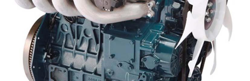
8 Mechanical Components: WG1605 engines are similar to V1505. Some differences include: Intake and exhaust manifolds. Positive Crankcase Ventilation system. Pistons. Cylinder heads and valves. Crankcase, Camshaft.
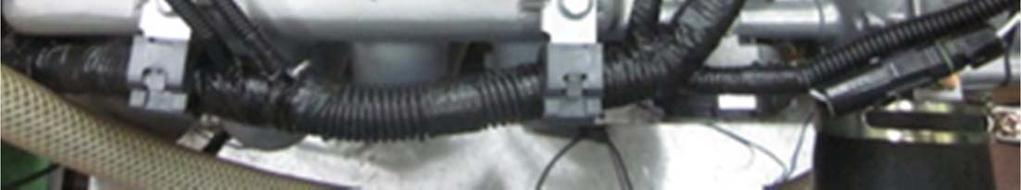
9 Intake & Exhaust Manifolds: Intake manifolds use longer runners Exhaust manifolds are shielded and engineered for higher temperatures

 System:")

10 Positive Crankcase Ventilation (PCV) System: PCV Valve Controls amount of blow-by gas and fresh air.
11 Pistons and Rings: Dished pistons are the main combustion chamber. (Gaseous compression ratios are nearly a third of a comparable diesel.) Top Ring: Barrel Shape Second Ring: Tapered Oil Control Ring

12 Cylinder Head and Valves: Spark plugs are recessed in head, and protrude into the main combustion chamber. Valves are equipped with special heat resistant alloy.

13 Piston Recession Example:

14 Cross-Flow Cylinder Head: Low heat conduction between intake and exhaust ports.
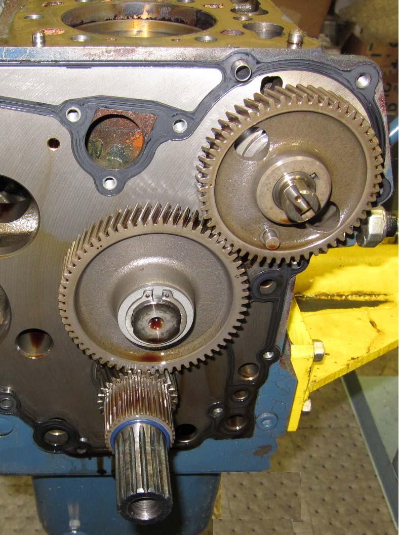
15 Camshaft: The camshaft s timing pin (5), is attached to the gear (4).
16 Gear shaft: The gear shaft deletes the fuel cam from the 05-E3B engine.

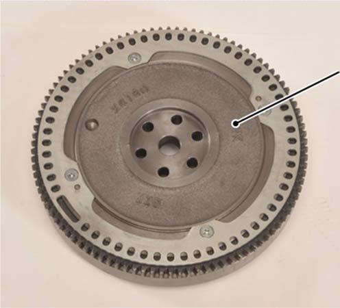
17 Flywheel: The WG1605 flywheel is designed to work alongside the crankshaft sensor.
.")
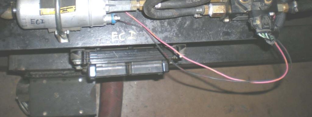
18 Fuel Delivery Pipe and Injectors: ECU controlled fuel delivery (pulse width modulated). Port Fuel Injection Fuel Pressure PSI* *(can fluctuate between 35-75#)

19 Fuel Delivery Pipe and Injectors:


20 Fuel Delivery Pipe and Injectors: 12-Volt operation 2-wire injector Pulse-width modulation ECU Controlled ground driver.
21 Three Way Catalyst: A 3-way catalyst oxidizes: (1)HC CO2 and H20 (2) CO CO2 (3) NOx N2
22 Electronic Control Unit, ECU: Utilizes inputs from the engine sensors to precisely meter fuel, control speed and remain emission compliant.

23 Electronic Control Unit, ECU:
24 ECU Wiring Diagram:

25 ECU Inputs and Outputs:

26 Ignition Coil: ECU controlled inductive coils. As primary windings dwell then collapse, the secondary windings yield a high voltage output via the spark plug.
27 Ignition Coil:


28 Gasoline System: Fuel lines are bold black color. Electrical circuits are think black.

29 Electric Fuel Pump: Variable controlled by ECU.


30 Electric Fuel Pump:
 through ECU.")
31 Electric Fuel Pump: Power to pump supplied by ECU controlled relay. Fuel pump is Pulse Width Modulated (PWM) through ECU.

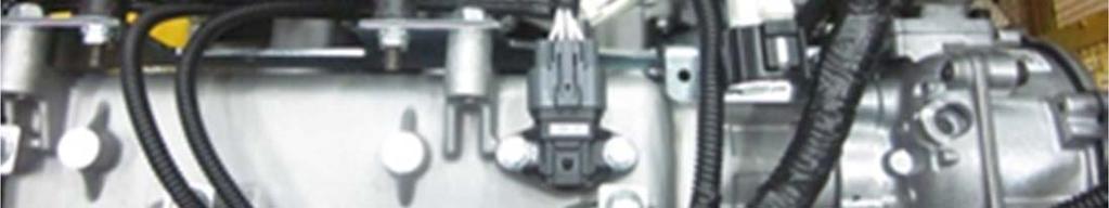
32 Fuel Pressure Manifold, FPM: Press/Temp Sensor Outlet Return Inlet Manifold
33 Fuel Pressure Manifold, FPM:

34 LPG Fuel Content: Propane / Butane ratio chart. Depending on energy content, spark timing is adjusted. Note: pressure at low temperatures.
35 LPG Tank and Filter: 1. Liquid Output 2. Quick Fill Valve 3. Safety Valve 4. 80% Fill Valve 5. Gauge 6. Vapor Pickup Tube 7. 80% Fill Valve Tube 8. Gauge Float 9. Liquid Pickup Tube


36 Lock Off Valve: Normally closed. Grounded provided by ECU. Pilot opens, allowing pressure to outlet side. Pressure begins to equalize and main valve opens fully. Pilot

37 Lock Off Valve: No electrical fault codes for valve.


38 Dual Stage Regulator, DSR: Regulator performs 2 functions: Vaporizes liquid fuel Regulates fuel pressure Only maintenance is periodic draining See maintenance schedule Coolant Fuel Inlet Primary Test Port Secondary Fuel Outlet
39 DSR Exploded View:
40
41 DEPR (Direct Electronic Pressure Regulator): Stand alone module Controlled via CAN from ECU Contains: Control Module Pressure/Temp. sensor Fast acting solenoid valve

42 DEPR Electrical: DTC s are communicated to ECU via CAN Harness pin out shown below (terminal view of engine harness) No user serviceable parts inside Cavity Color Function 1 WT CAN Termination 2 DB/PK CAN H 3 PK/DG Power Relay Output 4 BK Ground 5 DB/WT CAN L 6 RD/TN B+ from Fuse 2
43

44 Mixer: All mechanical unit No electrical/elec tronic controls
45


46 Engine Coolant Temperature:

47 Engine Coolant Temperature: Temperature Sensor Senses engine temperature for running and shutdown
48 Oil Pressure Switch: If oil pressure falls below specification, the warning lamp will illuminate. (ECU pin 35) Note: water ingress may also cause the contacts to corrode and cause false illumination, especially with LEDs.
49 Oil Pressure Switch: Standard Kubota Oil Pressure Switch: Closed: 0-7 psi Open > 7psi

50 Electronic Throttle Body, ETB ECU controlled, electronic motor driven mechanical throttle body connected to the intake.


51 Electronic Throttle Body, ETB Electric motor connected to throttle. ECU controlled based on foot pedal input.
52 Electronic Throttle Body, ETB Dual throttle position sensors, FPP1 and FPP2. Depending on the specification, TPS faults force engine idle or shutdown. KEA standard: FPP1 0-5v and FPP v.
53 Electronic Throttle Body, ETB
54 Oxygen (O 2 ) Sensor: Pre and Post catalyst feedback control for precise air-fuel ratio management. 4 wire sensor including heater.
55 Oxygen (O 2 ) Sensor: Pre- and Post-Catalyst Oxygen sensors

 senses")

56 Oxygen (O 2 ) Sensor: Heated for more accuracy, beyond exhaust temps. HEGO1 (pre-cat) senses rich/lean to adjust fuel mixture. HEGO2 (post-cat) checks catalyst for efficiency.
57 Oxygen (O 2 ) Sensor: Lean Zone Theoretical air/fuel ratio Rich Zone Feedback Control (Closed Loop) Orange line is air fuel ratio as controlled by the ECU based on O 2 sensor feedback. Oxygen sensor is sensing mixture and providing feedback. WG1605 is in Open Loop for one minute after start up (predetermined fuel mixture, not controlled by oxygen sensor), then is controlled by closedloop mode for all operating parameters.
58 Pre-Cat O 2 Sensor: Bosch LSF4 sensor Pre-cat used for closed loop fuel control Used as a rich-lean switch Only 1 DTC: EGO 1 Open/Lazy
59 Pre-Cat O 2 Sensor electrical:
60 Post-Cat O 2 Sensor: Bosch LSF4 sensor Post-cat used mainly for catalyst efficiency checking Post cat O 2 failure should not cause an engine running problem Only 1 DTC: EGO 2 Open/Lazy
61 Post-Cat O 2 Sensor electrical:


62 Normal O 2 Switching:

63 O 2 Sensor Testing: Test located at bottom right of Tests page Automated tests Tests sensor integrity and response Tests pre then post sensor Pre must pass before post can be tested Test status provides notification of failure type and appropriate DTC sets Test Status Indicator

64 Temperature and Manifold Absolute Pressure Sensor: TMAP. Mounted in the intake manifold and provides ECU data to calculate air flow pressure and density.


65 Temperature and Manifold Absolute Pressure Sensor: Combines both intake air temperature and intake manifold pressure Will compensate for intake temperature, altitude, and air cleaner restriction
66 Temperature and Manifold Absolute Pressure Sensor:

67 Crankshaft Position Sensor: Provides engine RPM information to the ECU.

68 Crankshaft Position Sensor:


69 Camshaft Position Sensor: Identifies which cylinders are in compression to begin spark timing.

70 Camshaft Position Sensor:


71 Cam and Crank Sensors: Cam 18 o ATDC #1 Compression Crank TDC TDC
72 Knock Sensor: Early detonation detection via mechanical vibration at the cylinder head/block deck level.


73 Knock Sensor: Reacts with a specific frequency from detonation. When knock is detected, voltage output is increased. ECU retards ignition timing. Installed sensor at degrees from vertical.


74 Service Manuals Workshop & Diagnosis Manuals

75 Service Tool E-Com Interface Device Connects between USB port and connection on engine Can be connected any time, engine running or not


76 Service Tool Interface Connector

77 Service Tool Software Interface available through KEA s Parts Department. Software is Free, and available for download through K-ISS.
78 Service Tool


79 Service Tool A B Data Monitor page can be chosen using either Page on Menu Bar or arrows Historic Faults: Shows historic data. This can only be erased using the service tool Active Faults: Shows realtime ECU data.

80 Service Tool Snap Shot Data Right click the icons you want to see and push P on keyboard
81 Service Tool Diagnostic Trouble Codes (DTC s) DTC s will only display with key on
82 Service Tool Diagnostic Trouble Codes Active DTC
83 Service Tool DTC Fault Information Double click on box next to DTC to display Historic Fault Information
84 Service Tool DTC Fault Information Snap Shot
85 Service Tool DTC Fault Information Flight Data Recorder 8 Seconds before fault, 2 Seconds after fault
86 Service Tool Erasing Historic DTC s Click on Clear All Faults

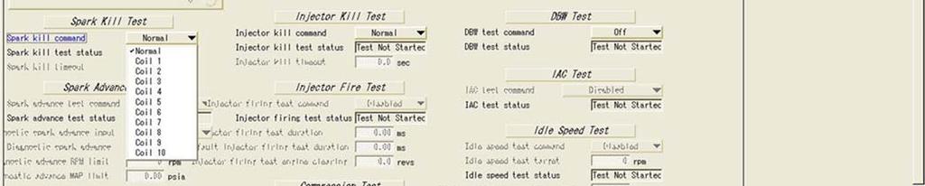
87 Service Tool Test Screen
88 Service Tool Spark Kill Test


89 Service Tool Injector Kill Test
90 Service Tool Drive By Wire (DBW) Test
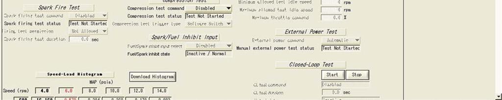
91 Service Tool Closed Loop Test
92 Engine Mechanical Damage If the engine is mechanically damaged it will not move O 2 properly (i.e. piston or ring damage, valve not sealing) This will cause a low O2 condition in the exhaust and the ECU will react by SUBTRACTING fuel in the CL-BM program (if in closed loop operation) Fuel pressure problems can cause the system to go rich or lean also VERIFY CORRECT FUEL PRESSURE (ALSO VOLUME)
93 Engine Mechanical Damage Bad sensor inputs to the engine can cause the system to go rich or lean depending on the failure For example: a bad MAP input can either starve or flood and engine depending on how it fails ALWAYS VALIDATE THAT THE SENSOR INPUTS ARE ACCURATE

94 GCP Display Gauge Page

95 GCP Raw Volts Page

96 GCP Display Service 1 Page

97 GCP Display Service 2 Page

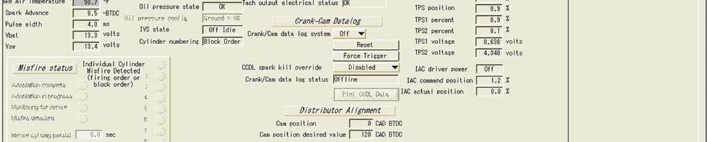
98 GCP Display Tests Page

99 GCP Display Test Page

100 GCP Display Faults Page
PSI ENGINE CODES CODE LIST
 2007 2009 PSI ENGINE CODES BLINK CODE FUNCTION Although the DST is considered a required tool to access the DTC codes, codes may be retrieved without a laptop computer using the blink code function. To
EMISSION CONTROL (AUX. EMISSION CONTROL DEVICES) H6DO
 H6DO") EMISSION CONTROL (AUX. EMISSION CONTROL DEVICES) H6DO SYSTEM OVERVIEW 1. System Overview There are three emission control systems, which are as follows: Crankcase emission control system Exhaust emission
EMISSION CONTROL (AUX. EMISSION CONTROL DEVICES) H6DO SYSTEM OVERVIEW 1. System Overview There are three emission control systems, which are as follows: Crankcase emission control system Exhaust emission
4.0L CEC SYSTEM Jeep Cherokee DESCRIPTION OPERATION FUEL CONTROL DATA SENSORS & SWITCHES
 4.0L CEC SYSTEM 1988 Jeep Cherokee 1988 COMPUTERIZED ENGINE Controls ENGINE CONTROL SYSTEM JEEP 4.0L MPFI 6-CYLINDER Cherokee, Comanche & Wagoneer DESCRIPTION The 4.0L engine control system controls engine
5. Control System CONTROL SYSTEM FUEL INJECTION (FUEL SYSTEM) A: GENERAL FU(H4DOTC)-29
 A: GENERAL FU(H4DOTC)-29") W1860BE.book Page 29 Tuesday, January 28, 2003 11:01 PM 5. Control System A: GENERAL The ECM receives signals from various sensors, switches, and other control modules. Using these signals, it determines
W1860BE.book Page 29 Tuesday, January 28, 2003 11:01 PM 5. Control System A: GENERAL The ECM receives signals from various sensors, switches, and other control modules. Using these signals, it determines
EMISSION CONTROL (AUX. EMISSION CONTROL DEVICES) H4DOTC
 H4DOTC") EMISSION CONTROL (AUX. EMISSION CONTROL DEVICES) H4DOTC SYSTEM OVERVIEW 1. System Overview There are three emission control systems, which are as follows: Crankcase emission control system Exhaust emission
EMISSION CONTROL (AUX. EMISSION CONTROL DEVICES) H4DOTC SYSTEM OVERVIEW 1. System Overview There are three emission control systems, which are as follows: Crankcase emission control system Exhaust emission
5. Control System CONTROL SYSTEM FUEL INJECTION (FUEL SYSTEM) A: GENERAL. FU(STi)-27
 A: GENERAL. FU(STi)-27") W1860BE.book Page 27 Tuesday, January 28, 2003 11:01 PM 5. Control System A: GENERAL The ECM receives signals from various sensors, switches, and other control modules. Using these signals, it determines
W1860BE.book Page 27 Tuesday, January 28, 2003 11:01 PM 5. Control System A: GENERAL The ECM receives signals from various sensors, switches, and other control modules. Using these signals, it determines
EMISSION CONTROL (AUX. EMISSION CONTROL DEVICES) H4SO
 H4SO") EMISSION CONTROL (AUX. EMISSION CONTROL DEVICES) H4SO SYSTEM OVERVIEW 1. System Overview There are three emission control systems, which are as follows: Crankcase emission control system Exhaust emission
EMISSION CONTROL (AUX. EMISSION CONTROL DEVICES) H4SO SYSTEM OVERVIEW 1. System Overview There are three emission control systems, which are as follows: Crankcase emission control system Exhaust emission
Fuel Metering System Component Description
 1999 Chevrolet/Geo Tahoe - 4WD Fuel Metering System Component Description Purpose The function of the fuel metering system is to deliver the correct amount of fuel to the engine under all operating conditions.
2012 Chevy Truck Equinox FWD L4-2.4L Vehicle > Locations > Components
 2012 Chevy Truck Equinox FWD L4-2.4L Vehicle > Locations > Components 2012 Chevy Truck Equinox FWD L4-2.4L Vehicle > Powertrain Management > Fuel Delivery and Air Induction > Description and Operation
Lotus Service Notes Section EMR
 ENGINE MANAGEMENT SECTION EMR Lotus Techcentre Sub-Section Page Diagnostic Trouble Code List EMR.1 3 Component Function EMR.2 7 Component Location EMR.3 9 Diagnostic Guide EMR.4 11 CAN Bus Diagnostics;
FUEL INJECTION SYSTEM - MULTI-POINT
 FUEL INJECTION SYSTEM - MULTI-POINT 1988 Jeep Cherokee 1988 Electronic Fuel Injection JEEP MULTI-POINT 4.0L Cherokee, Comanche, Wagoneer DESCRIPTION The Multi-Point Electronic Fuel Injection (EFI) system
2015 PSI 8.8L LPG Engine Overview. Study Guide. Course Code: 8777
 2015 PSI 8.8L LPG Engine Overview Study Guide Course Code: 8777 1 2015 PSI 8.8L LPG Engine Overview Study Guide 2015 Navistar, Inc. 2701 Navistar Drive, Lisle, IL 60532. All rights reserved. No part of
G - TESTS W/CODES - 2.2L
 G - TESTS W/CODES - 2.2L 1994 Toyota Celica 1994 ENGINE PERFORMANCE Toyota 2.2L Self-Diagnostics Celica INTRODUCTION If no faults were found while performing F - BASIC TESTING, proceed with self-diagnostics.
DTC P0171, P0172, P0174, or P0175
 Page 1 of 6 2009 Pontiac G8 G8 Service Manual Document ID: 2076050 DTC P0171, P0172, P0174, or P0175 Diagnostic Instructions Perform the Diagnostic System Check - Vehicle prior to using this diagnostic
Diagnostic Trouble Code (DTC) List - Vehicle
 List - Vehicle") Document ID# 850406 2002 Pontiac Firebird Diagnostic Trouble Code (DTC) List - Vehicle DTC DTC 021 and/or 031 DTC 022 and/or 032 DTC 023 or 033 DTC 24/34 DTC 025 and/or 035 DTC 041 DTC 042 DTC 043 DTC
Document ID# 850406 2002 Pontiac Firebird Diagnostic Trouble Code (DTC) List - Vehicle DTC DTC 021 and/or 031 DTC 022 and/or 032 DTC 023 or 033 DTC 24/34 DTC 025 and/or 035 DTC 041 DTC 042 DTC 043 DTC
DIAGNOSTIC TROUBLE CODE CHART HINT:
 DIAGNOSTICS DIAGNOSTIC TROUBLE CODE CHART HINT: SFI SYSTEM (1MZFE) 05241 Parameters listed in the chart may not be exactly the same as your reading due to the type of instrument or other factors. If a
Powertrain DTC Summaries EOBD
 Powertrain DTC Summaries Quick Reference Diagnostic Guide Jaguar X-TYPE 2.5L and 3.0L 2001.5 Model Year Revised January, 2002: P0706, P0731, P0732, P0733, P0734, P0735, P0740, P1780 POSSIBLE CAUSES Revised
Lotus Service Notes Section EMD
 ENGINE MANAGEMENT SECTION EMD Lotus Techcentre Sub-Section Page Diagnostic Trouble Code List EMD.1 3 Component Function EMD.2 8 Component Location EMD.3 10 Diagnostic Guide EMD.4 11 CAN Bus Diagnostics;
Powertrain DTC Summaries EOBD
 Powertrain DTC Summaries Quick Reference Diagnostic Guide Jaguar X-TYPE 2.0 L 2002.25 Model Year Refer to page 2 for important information regarding the use of Powertrain DTC Summaries. Jaguar X-TYPE 2.0
DIAGNOSTIC TROUBLE CODE CHART
 DIAGNOSTIC TROUBLE CODE CHART 05 35 HINT: As for the vehicle for MEXICO, refer to Repair Manual 2003 COROLLA MATRIX (Pub. No. RM940U). Parameters listed in the chart may not be exactly the same as your
Powertrain DTC Summaries OBD II
 Powertrain DTC Summaries Quick Reference Diagnostic Guide Jaguar X-TYPE 2.5L and 3.0L 2002 Model Year Revised January, 2002: P0706, P0731, P0732, P0733, P0734, P0735, P0740, P1780 POSSIBLE CAUSES Revised
Powertrain DTC Summaries EOBD
 Powertrain DTC Summaries Quick Reference Diagnostic Guide Jaguar S-TYPE V6, V8 N/A and V8 SC 2002.5 Model Year Refer to pages 2 9 for important information regarding the use of Powertrain DTC Summaries.
The engine control module (ECM) uses the following information to calculate an expected airflow rate.
 uses the following information to calculate an expected airflow rate.") DTC Descriptors DTC Mass Air Flow (MAF) sensor performance Circuit/System Description The engine control module (ECM) uses the following information to calculate an expected airflow rate. The throttle
DTC Descriptors DTC Mass Air Flow (MAF) sensor performance Circuit/System Description The engine control module (ECM) uses the following information to calculate an expected airflow rate. The throttle
2UZ-FE ENGINE CONTROL SYSTEM SFI SYSTEM
 160 2UZ-FE EINE CONTROL SYSTEM SFI SYSTEM DTC P0171 System Too Lean (Bank 1) DTC P0172 System Too Rich (Bank 1) DTC P0174 System Too Lean (Bank 2) DTC P0175 System Too Rich (Bank 2) DCRIPTION The fuel
5. Engine Control Module (ECM) I/O Signal
 I/O Signal") 5. A: ELECTRICAL SPECIFICATION B134 B135 B136 B137 17 16 15 14 13 12 11 10 9 8 27 26 25 24 23 22 21 20 19 18 34 33 32 31 30 29 28 19 18 17 16 15 14 13 12 11 10 9 8 27 26 25 24 23 22 21 20 35 34 33 32 31
5. A: ELECTRICAL SPECIFICATION B134 B135 B136 B137 17 16 15 14 13 12 11 10 9 8 27 26 25 24 23 22 21 20 19 18 34 33 32 31 30 29 28 19 18 17 16 15 14 13 12 11 10 9 8 27 26 25 24 23 22 21 20 35 34 33 32 31
DTC P0171 SYSTEM TOO LEAN (BANK 1) DTC P0174 SYSTEM TOO LEAN (BANK 2)
 DTC P0174 SYSTEM TOO LEAN (BANK 2)") 05498 DIAGNOSTICS DTC P0171 SYSTEM TOO LEAN (BANK 1) 05EXR06 DTC P0172 SYSTEM TOO RICH (BANK 1) DTC P0174 SYSTEM TOO LEAN (BANK 2) DTC P0175 SYSTEM TOO RICH (BANK 2) CIRCUIT DESCRIPTION The fuel trim is
05498 DIAGNOSTICS DTC P0171 SYSTEM TOO LEAN (BANK 1) 05EXR06 DTC P0172 SYSTEM TOO RICH (BANK 1) DTC P0174 SYSTEM TOO LEAN (BANK 2) DTC P0175 SYSTEM TOO RICH (BANK 2) CIRCUIT DESCRIPTION The fuel trim is
E - THEORY/OPERATION - TURBO
 E - THEORY/OPERATION - TURBO 1995 Volvo 850 1995 ENGINE PERFORMANCE Volvo - Theory & Operation 850 - Turbo INTRODUCTION This article covers basic description and operation of engine performance-related
Lotus Service Notes Section EMQ
 ENGINE MANAGEMENT SECTION EMQ Lotus Techcentre Sub-Section Page Component Function EMQ.1 3 Component Location EMQ.2 5 Diagnostic Trouble Code List EMQ.3 7 Diagnostic Guide EMQ.4 11 CAN Bus Diagnostics;
Diagnostic Trouble Code (DTC) Root Cause. for Omnitek ECM 64A/66A/88A. & Remedial Action
 Root Cause. for Omnitek ECM 64A/66A/88A. & Remedial Action") Diagnostic Trouble Code (DTC) Root Cause & Remedial Action for Omnitek ECM 64A/66A/88A Omnitek Engineering Corp. 1945 S Rancho Santa Fe Rd. San Marcos, CA 92078 Tel. 760-591-0089 - Fax. 760-591-0880 -
Diagnostic Trouble Code (DTC) Root Cause & Remedial Action for Omnitek ECM 64A/66A/88A Omnitek Engineering Corp. 1945 S Rancho Santa Fe Rd. San Marcos, CA 92078 Tel. 760-591-0089 - Fax. 760-591-0880 -
Propane and Gasoline Electronic Fuel Injection
 Zenith Electronic Engine Management System Propane and Gasoline Electronic Fuel Injection 1 Slide 1 2 Slide 2 Home Page System Advantages Block Diagram, Electronic Control Unit Inputs Output Controls System
DEUTZ Corporation 914 Gas. Customer / Event DEUTZ Corporation Presentation DATE, 2010
 DEUTZ Corporation 914 Gas Customer / Event DEUTZ Corporation Presentation DATE, 2010 914 Gas Content Target Market General Product Features Performance Data Dimensions and Weight Emissions Gas Train and
ENGINE MANAGEMENT SYSTEM. System Sensors
 ENGINE MANAGEMENT SYSTEM System Sensors Throttle position sensor - Used to relay throttle position information to the ECU. Throttle opening angle is used by the ECU to determine fuelling and ignition requirements
ARTICLE BEGINNING INTRODUCTION SELF-DIAGNOSTIC SYSTEM RETRIEVING DTCS ENGINE PERFORMANCE Volkswagen Self-Diagnostics - Gasoline
 Article Text ARTICLE BEGINNING 1996 ENGINE PERFORMANCE Volkswagen Self-Diagnostics - Gasoline Cabrio, Golf III, GTI, Jetta III, Passat INTRODUCTION If no faults were found while performing preliminary
Lotus Service Notes Section EMQ
 ENGINE MANAGEMENT SECTION EMQ Lotus Techcentre Sub-Section Page Cylinder Numbering 2 Component Function EMQ.1 3 Component Location EMQ.2 5 Diagnostic Trouble Code List EMQ.3 7 Diagnostic Guide EMQ.4 11
ENGINE AND EMISSION CONTROL
 17-1 GROUP 17 ENGINE AND EMISSION CONTROL CONTENTS ENGINE CONTROL 17-2 GENERAL INFORMATION 17-2 AUTO-CRUISE CONTROL SYSTEM 17-3 GENERAL INFORMATION 17-3 CONSTRUCTION AND OPERATION 17-5 17-7 GENERAL INFORMATION
ELECTRONIC ENGINE CONTROLS
 2005 Jaguar S-Type (X200) V8-4.2L Vehicle > Powertrain Management > Computers and Control Systems > Description and Operation > Components ELECTRONIC ENGINE CONTROLS Electronic Engine Controls Vehicles
MULTIPOINT FUEL INJECTION (MPI) <4G9>
 <4G9>") MULTIPOINT FUEL INJECTION (MPI) 13C-1 MULTIPOINT FUEL INJECTION (MPI) CONTENTS GENERAL................................. 2 Outline of Changes............................ 2 GENERAL INFORMATION...................
MULTIPOINT FUEL INJECTION (MPI) 13C-1 MULTIPOINT FUEL INJECTION (MPI) CONTENTS GENERAL................................. 2 Outline of Changes............................ 2 GENERAL INFORMATION...................
A: ENGINE CONTROL MODULE (ECM) I/O SIGNAL FOR MT VEHICLES. Signal (V) Ignition SW ON (Engine OFF) B B B
 I/O SIGNAL FOR MT VEHICLES. Signal (V) Ignition SW ON (Engine OFF) B B B") 5. Specified Data A: ENGINE CONTROL MODULE (ECM) I/O SIGNAL FOR MT VEHICLES B2M2267A Crankshaft Camshaft Throttle Rear oxygen Front oxygen (A/F) heater Rear oxygen heater Engine coolant temperature Signal
5. Specified Data A: ENGINE CONTROL MODULE (ECM) I/O SIGNAL FOR MT VEHICLES B2M2267A Crankshaft Camshaft Throttle Rear oxygen Front oxygen (A/F) heater Rear oxygen heater Engine coolant temperature Signal
NEW FEATURES 3E E ENGINE. 1. Description 12 TERCEL NEW FEATURES
 12 TERCEL NEW FEATURES NEW FEATURES 3E E ENGINE 1. Description The 3E E engine is based on the 1.5 liter, 12 valve, OHC 3E engine, but with fuel injection, ignition timing and other engine functions controlled
DTC Summaries. NipponDenso V12 Engine Management
 DTC Summaries NipponDenso V12 Engine Management OBD II MONITORING CONDITIONS: When testing for DTC reoccurrence, it can be determined if the Service Drive Cycle was of sufficient length by performing a
2002 ENGINE PERFORMANCE. Self-Diagnostics - RAV4. Before performing testing procedures, check for any related Technical Service Bulletins (TSBs).
.") 2002 ENGINE PERFORMANCE Self-Diagnostics - RAV4 INTRODUCTION NOTE: Before performing testing procedures, check for any related Technical Service Bulletins (TSBs). To properly diagnosis and repair this
2002 ENGINE PERFORMANCE Self-Diagnostics - RAV4 INTRODUCTION NOTE: Before performing testing procedures, check for any related Technical Service Bulletins (TSBs). To properly diagnosis and repair this
Engine mechanics. Crankcase ventilation outlet
 Engine mechanics Crankcase ventilation outlet The gases are drawn out of the crankcase by the vacuum in the intake manifold. The oil is separated from the gases in the labyrinth and in the cyclone oil
Auto Diagnosis Test #7 Review
 Auto Diagnosis Test #7 Review Your own hand written notes may be used for the 1 st 10 minutes of the test Based on Chapters 25, 26, 32, 33, 34 and Lab Demonstrations Auto Diagnosis Test #7 Review Your
For Troubleshooting of DTC related components, see chart on page INTAKE AIR BYPASS (IAB) HIGH CONTROL SOLENOID
 HIGH CONTROL SOLENOID") Index For Troubleshooting of DTC related components, see chart on page 11-53. '96-99 models: EXHAUST GAS RECIRCULATION (EGR) and LIFT MANIFOLD ABSOLUTE PRESSURE (MAP) INTAKE AIR BYPASS (IAB) HIGH page
Index For Troubleshooting of DTC related components, see chart on page 11-53. '96-99 models: EXHAUST GAS RECIRCULATION (EGR) and LIFT MANIFOLD ABSOLUTE PRESSURE (MAP) INTAKE AIR BYPASS (IAB) HIGH page
DIAGNOSTIC TROUBLE CODE CHART
 DIAGNOSTIC TROUBLE CODE CHART HINT: DI231 Parameters listed in the chart may not be exactly the same as your readings due to the type of instrument or other factors. If a malfunction code is displayed
MULTIPOINT FUEL INJECTION (MPI) <4G63-Turbo>
 <4G63-Turbo>") 13B-1 GROUP 13B MULTIPOINT FUEL INJECTI (MPI) CTENTS GENERAL INFORMATI........ 13B-2 SENSOR....................... 13B-8 THROTTLE VALVE OPENING ANGLE CTROL.............. 13B-9 FUEL INJECTI
13B-1 GROUP 13B MULTIPOINT FUEL INJECTI (MPI) CTENTS GENERAL INFORMATI........ 13B-2 SENSOR....................... 13B-8 THROTTLE VALVE OPENING ANGLE CTROL.............. 13B-9 FUEL INJECTI
SYTY Trouble Code: ALDL INFORMATION
 SYTY Trouble Code: ALDL INFORMATION A -- Ground G -- Fuel Pump B -- Diagnostic Terminal H -- Brake Sense Speed Input F -- TCC M -- Serial Data (special tool needed - Do Not Use) For ECM Trouble Codes,
Fuel System Description
 Page 1 of 9 2005 Pontiac GTO GTO (VIN V) Service Manual Engine Engine Controls - 6.0L Description and Operation Document ID: 1550920 Fuel System Description System Overview The fuel tank stores the fuel
MULTIPORT FUEL SYSTEM (MFI) <2.4L ENGINE>
 <2.4L ENGINE>") 13B-1 GROUP 13B MULTIPORT FUEL SYSTEM (MFI) CONTENTS GENERAL DESCRIPTION 13B-2 CONTROL UNIT 13B-5 SENSOR 13B-7 ACTUATOR 13B-24 FUEL INJECTION CONTROL 13B-31 IGNITION TIMING AND CONTROL FOR
13B-1 GROUP 13B MULTIPORT FUEL SYSTEM (MFI) CONTENTS GENERAL DESCRIPTION 13B-2 CONTROL UNIT 13B-5 SENSOR 13B-7 ACTUATOR 13B-24 FUEL INJECTION CONTROL 13B-31 IGNITION TIMING AND CONTROL FOR
2002 Buick Rendezvous - AWD
 2002 Buick Rendezvous - AWD DTC P0410 Description The control module activates the secondary air injection (AIR) system by grounding both the pump relay and the vacuum control solenoid control circuits.
The 1.4 ltr. and 1.6 ltr. FSI engine with timing chain
 Service. Self study programme 296 The 1.4 ltr. and 1.6 ltr. FSI engine with timing chain Design and function For Volkswagen, new and further development of engines with direct petrol injection is an important
ENGINE CONTROL SYSTEM. 1. General ENGINE 3VZ FE ENGINE
 ENGINE 3VZ FE ENGINE 69 ENGINE CONTROL SYSTEM 1. General The engine control system for the 3VZ FE engine has the same basic construction and operation as for the 2VZ FE engine. However, the sequential
Sensors & Controls. Everything you wanted to know about gas engine ignition technology but were too afraid to ask.
 Everything you wanted to know about gas engine ignition technology but were too afraid to ask. Contents 1. Introducing Electronic Ignition 2. Inductive Ignition 3. Capacitor Discharge Ignition 4. CDI vs
Diagnostic Trouble Code (DTC) memory, checking and erasing
 memory, checking and erasing") Page 1 of 49 01-12 Diagnostic Trouble Code (DTC) memory, checking and erasing Check DTC Memory (function 02) - Connect VAS5051 tester Page 01-7 and select vehicle system "01 - Engine electronics". Engine
Page 1 of 49 01-12 Diagnostic Trouble Code (DTC) memory, checking and erasing Check DTC Memory (function 02) - Connect VAS5051 tester Page 01-7 and select vehicle system "01 - Engine electronics". Engine
DTC P0134 OXYGEN SENSOR CIRCUIT NO ACTIVITY DETECTED (BANK 1 SENSOR 1)
") 05114 DIAGNOSTICS 05CRQ04 DTC P0134 OXYGEN SENSOR CIRCUIT NO ACTIVITY DETECTED (BANK 1 SENSOR 1) CIRCUIT DESCRIPTION Refer to DTC P0130 on page 0596. DTC No. DTC Detecting Condition Trouble Area After
05114 DIAGNOSTICS 05CRQ04 DTC P0134 OXYGEN SENSOR CIRCUIT NO ACTIVITY DETECTED (BANK 1 SENSOR 1) CIRCUIT DESCRIPTION Refer to DTC P0130 on page 0596. DTC No. DTC Detecting Condition Trouble Area After
P0030, P0036, P0050, P0053, P0054, P0056, P0059, P0060, P0135, P0141, P0155, or P0161
 DTC Descriptors DTC P0030 HEGO Heater Control Circuit Bank 1 Sensor 1 DTC P0036 HEGO Heater Control Circuit Bank 1 Sensor 2 DTC P0050 HEGO Heater Control Circuit Bank 2 Sensor 1 DTC P0053 HEGO Heater Resistance
EMISSION CONTROL VISUAL INSPECTION PROCEDURES
 EMISSION CONTROL VISUAL INSPECTION PROCEDURES 1992 Infiniti G20 1983-98 GENERAL INFORMATION Emission Control Visual Inspection Procedures All Models * PLEASE READ THIS FIRST * This article is provided
Engine Cranks But Does Not Run
 Page 1 of 5 2000 GMC Truck GMC K Sierra - 4WD Sierra, Silverado, Suburban, Tahoe, Yukon (VIN C/K) Service Manual Engine Engine Controls - 4.8L, 5.3L, and 6.0L Diagnostic Information and Procedures Engine
MULTIPORT FUEL SYSTEM (MFI)
") 13A-1 GROUP 13A CONTENTS GENERAL INFORMATION...13A-2 CONTROL UNIT...13A-7 SENSOR...13A-9 ACTUATOR...13A-26 FUEL INJECTION CONTROL...13A-31 IGNITION TIMING AND CONTROL FOR CURRENT CARRYING TIME...13A-36
13A-1 GROUP 13A CONTENTS GENERAL INFORMATION...13A-2 CONTROL UNIT...13A-7 SENSOR...13A-9 ACTUATOR...13A-26 FUEL INJECTION CONTROL...13A-31 IGNITION TIMING AND CONTROL FOR CURRENT CARRYING TIME...13A-36
EvoX EFI ECU Pinouts Last Updated Tuesday, 24 April :40
 HOW TO: Reset your Fuel trims... Open your bonnet, open the fuse box, pull out 7.5A number 2 fuse, this is battery backup for your main ECU, remove for 2 seconds, and replace. Your fuel trims and learned
SPN 3227 or Suspect Parameter Number (SPN) and Failure Mode Indicator (FMI) Description
 and Failure Mode Indicator (FMI) Description") SPN 3227 or 3266 Suspect Parameter Number (SPN) and Failure Mode Indicator (FMI) Description SPN FMI Description Possible Causes 3227 4 EGO Bank A Sensor 2 Open or short to ground on Voltage Low signal
SPN 3227 or 3266 Suspect Parameter Number (SPN) and Failure Mode Indicator (FMI) Description SPN FMI Description Possible Causes 3227 4 EGO Bank A Sensor 2 Open or short to ground on Voltage Low signal
A rotary solenoid type ISC system is used, which controls the fast idle and idle speeds.
 44 ENGINE 5S FE ENGINE ENGINE CONTROL SYSTEM 1. General Basic functions of the engine control system of the new 5S FE engine for the new Camry are the same as those in the 5S FE engine for the 90 model
5. Engine Control Module (ECM) I/O Signal S008526
 I/O Signal S008526") 5. Engine Control Module (ECM) I/O Signal S008526 A: ELECTRICAL SPECIFICATION S008526A08 1. MT VEHICLES S008526A0801 B2M2267A Crankshaft Camshaft Throttle Rear oxygen Front oxygen (A/F) heater Rear oxygen
5. Engine Control Module (ECM) I/O Signal S008526 A: ELECTRICAL SPECIFICATION S008526A08 1. MT VEHICLES S008526A0801 B2M2267A Crankshaft Camshaft Throttle Rear oxygen Front oxygen (A/F) heater Rear oxygen
H - TESTS W/O CODES Nissan 240SX INTRODUCTION TROUBLE SHOOTING SYMPTOMS DIAGNOSIS WILL NOT START
 H - TESTS W/O CODES 1990 Nissan 240SX 1990 ENGINE PERFORMANCE Trouble Shooting - No Codes Nissan; 240SX, Axxess, Maxima, Pathfinder, Pickup, Pulsar, Sentra, Van, INTRODUCTION Before diagnosing symptoms
ENGINE CONTROL SECTION EC CONTENTS
 ENGINE CONTROL SECTION EC CONTENTS PRECAUTIONS... EC-3 On Board Diagnostic (OBD) System of Engine... EC-3 Precaution... EC-3 PREPARATION... EC-6 Special Service Tools... EC-6 DESCRIPTION... EC-7 Description...
DTC P0174 Fuel Trim System Lean Bank 2
 2000 Chevrolet/Geo S10 Pickup - 4WD DTC P0174 Fuel Trim System Lean Bank 2 Circuit Description In order to provide the best possible combination of driveability, fuel economy, and emission control, the
Setup Tabs. Basic Setup: Advanced Setup:
 Setup Tabs Basic Setup: Password This option sets a password that MUST be entered to re-enter the system. Note: ProEFI can NOT get you into the calibration if you lose this password. You will have to reflash
ProECU Subaru DIT. DTC List 2012-onward Model Year. v1.0
 ProECU Subaru DIT DTC List 2012-onward Model Year v1.0 Engine DTC List P000A A CAMSHAFT POSITION SLOW RESPONSE (BANK 1) P000B B CAMSHAFT POSITION SLOW RESPONSE (BANK 1) P000C A CAMSHAFT POSITION SLOW RESPONSE
ENGINE AND EMISSION CONTROL
 17-1 ENGINE AND EMISSION CONTROL CONTENTS ENGINE CONTROL SYSTEM........ 3 SERVICE SPECIFICATION............... 3 ON-VEHICLE SERVICE.................. 3 Accelerator Cable Check and Adjustment... 3 ACCELERATOR
MULTIPOINT FUEL INJECTION (MPI) <4G63-Non-Turbo>
 <4G63-Non-Turbo>") 13A-1 GROUP 13A MULTIPOINT FUEL INJECTI (MPI) CTENTS GENERAL INFORMATI........ 13A-2 FUEL INJECTI CTROL...... 13A-6 IDLE SPEED CTROL (ISC)..... 13A-7 IGNITI TIMING AND DISTRIBUTI CTROL........
13A-1 GROUP 13A MULTIPOINT FUEL INJECTI (MPI) CTENTS GENERAL INFORMATI........ 13A-2 FUEL INJECTI CTROL...... 13A-6 IDLE SPEED CTROL (ISC)..... 13A-7 IGNITI TIMING AND DISTRIBUTI CTROL........
Diagnostic Trouble Code (DTC) table
 table") Page 1 of 40 01-19 Diagnostic Trouble Code (DTC) table Note: When malfunctions occur in monitored sensors or components, Diagnostic Trouble Codes (DTCs) are stored in DTC memory with a description of the
Page 1 of 40 01-19 Diagnostic Trouble Code (DTC) table Note: When malfunctions occur in monitored sensors or components, Diagnostic Trouble Codes (DTCs) are stored in DTC memory with a description of the
DTC P0171 SYSTEM TOO LEAN (BANK 1) DTC P0172 SYSTEM TOO RICH (BANK 1) DTC P0174 SYSTEM TOO LEAN (BANK 2) DTC P0175 SYSTEM TOO RICH (BANK 2)
 DTC P0172 SYSTEM TOO RICH (BANK 1) DTC P0174 SYSTEM TOO LEAN (BANK 2) DTC P0175 SYSTEM TOO RICH (BANK 2)") 05155 05NZ501 DTC P0171 SYSTEM TOO LEAN (BANK 1) DTC P0172 SYSTEM TOO RICH (BANK 1) DTC P0174 SYSTEM TOO LEAN (BANK 2) DTC P0175 SYSTEM TOO RICH (BANK 2) CIRCUIT DESCRIPTION These DTCs indicate that the
05155 05NZ501 DTC P0171 SYSTEM TOO LEAN (BANK 1) DTC P0172 SYSTEM TOO RICH (BANK 1) DTC P0174 SYSTEM TOO LEAN (BANK 2) DTC P0175 SYSTEM TOO RICH (BANK 2) CIRCUIT DESCRIPTION These DTCs indicate that the
 Page 1 of 18 2004 PCED On Board Diagnostics SECTION 5: Pinpoint Tests Procedure revision date: 10/26/2007 H: Fuel Control H: Introduction H1 PERFORM THE KOER SELF-TEST Engine at normal operating temperature.
2.8 Liter VR6 2V Fuel Injection & Ignition, Engine Code(s): AAA m.y
: AAA m.y") 2.8 Liter VR6 2V Fuel Injection & Ignition, Engine Code(s): AAA m.y. 1996-1997 01 - On Board Diagnostic (OBD) On Board Diagnostic (OBD II) Malfunction Indicator Lamp (MIL) On Board Diagnostic (OBD II),
2.8 Liter VR6 2V Fuel Injection & Ignition, Engine Code(s): AAA m.y. 1996-1997 01 - On Board Diagnostic (OBD) On Board Diagnostic (OBD II) Malfunction Indicator Lamp (MIL) On Board Diagnostic (OBD II),
Diagnostic Trouble Code (DTC) Guide for Omnitek ECM 64A/66A/88A
 Guide for Omnitek ECM 64A/66A/88A") Diagnostic Trouble Code (DTC) Guide for Omnitek ECM 64A/66A/88A Omnitek Engineering Corp. 1333 Keystone Way, #101 Vista, CA 92081 Tel. 760-591-0089 - Fax. 760-591-0880 - Copyright 2006 Omnitek Engineering,
Diagnostic Trouble Code (DTC) Guide for Omnitek ECM 64A/66A/88A Omnitek Engineering Corp. 1333 Keystone Way, #101 Vista, CA 92081 Tel. 760-591-0089 - Fax. 760-591-0880 - Copyright 2006 Omnitek Engineering,
DESCRIPTION Chevrolet Chevy Van 5.7L Eng G20. Service Manual: FUEL INJECTION SYSTEM - TBI
 Service Manual: FUEL INJECTION SYSTEM - TBI DESCRIPTION 1989 Chevrolet Chevy Van 5.7L Eng G20 The throttle body fuel injection system consists of 7 major sub-assemblies: fuel supply system, throttle body
P0030, P0036, -- P0135, P0141, P0155, P0161 P0030, P0036, P0050, P0056, P0135, P0141,
 Page 1 of 6 2008 Pontiac G8 DTC P0030, P0036, P0053, P0054, P0135, or P0141 Diagnostic Instructions Perform the Diagnostic System Check - Vehicle prior to using this diagnostic procedure. Review Strategy
13A-1 FUEL CONTENTS MULTIPOINT FUEL INJECTION (MPI) FUEL SUPPLY... 13B
 FUEL SUPPLY... 13B") 13A-1 FUEL CONTENTS MULTIPOINT FUEL INJECTION (MPI)... 13A FUEL SUPPLY... 13B 13A-2 MULTIPOINT FUEL INJECTION (MPI) CONTENTS GENERAL INFORMATION... 3 SERVICE SPECIFICATIONS... 6 SEALANT... 6 SPECIAL TOOLS...
13A-1 FUEL CONTENTS MULTIPOINT FUEL INJECTION (MPI)... 13A FUEL SUPPLY... 13B 13A-2 MULTIPOINT FUEL INJECTION (MPI) CONTENTS GENERAL INFORMATION... 3 SERVICE SPECIFICATIONS... 6 SEALANT... 6 SPECIAL TOOLS...
GM Enhanced Parameters
 GM Enhanced Parameters # of 4x Ref Pulses between CAM Counter # OF EGR ADAPTIVE LEARN MATRIX CELLS OUT OF RANGE High # OF EGR ADAPTIVE LEARN MATRIX CELLS OUT OF RANGE LOW 1-2 Adapt High Cell 1-2 Adapt
Lambda Control Fuel Adaptation and Fuel Trim
 Lambda Control Fuel Adaptation and Fuel Trim Q: What is Lambda and Lambda Control? A: In the case of a gasoline engine, the optimal mixture of air to fuel for complete combustion is a ratio of 14.7 parts
Automobili Lamborghini s.p.a. OBDII MY 07 Section 18 Page 1 FAULT CODE TABLE
 Automobili Lamborghini s.p.a. OBDII MY 07 Section 18 Page 1 FAULT CODE TABLE Automobili Lamborghini s.p.a. OBDII MY 07 Section 18 Page 2 DIAGNOSTIC TROUBLE CODE DEFINITIONS P0016 Crankshaft Position Camshaft
!"#$%&'()*+(,%&%-)-".&(/01*%)$"%&2(#2$&3456. This can be found in the camshaft housing and is included in the oil circuit of the engine.
*+(,%&%-)-.&(/01*%)$%&2(#2$&3456. This can be found in the camshaft housing and is included in the oil circuit of the engine.") !"#$%&'()*+(,%&%-)-".&(/01*%)$"%&2(#2$&3456 This can be found in the camshaft housing and is included in the oil circuit of the engine. Actuation of the inlet camshaft timing adjustment valve results in
!"#$%&'()*+(,%&%-)-".&(/01*%)$"%&2(#2$&3456 This can be found in the camshaft housing and is included in the oil circuit of the engine. Actuation of the inlet camshaft timing adjustment valve results in
SECONDARY PARAMETERS AND ENABLE CONDITIONS
 SECONDARY S AND Manifold Pressure Sensor Rationality Manifold Pressure Too Low Manifold Pressure Too High Intake Air Temperature Sensor Shorted Intake Air Temperature Sensor Open Coolant Temperature Sensor
System Description. General. Connectors. Summary Car Models TROUBLE-SHOOTING MULTEC 64
 SYSTEM DESCRIPTION System Description General is a combined control system for fuel injection and ignition. It also controls idle speed, EGR-valve etc. comes in both multipoint and singlepoint configurations.
DATA LIST / ACTIVE TEST
 2UZFE ENGINE CONTROL SYSTEM SFI SYSTEM 43 DATA LIST / ACTIVE TT 1. DATA LIST HINT: Using the intelligent tester's DATA LIST allows switch, sensor, actuator and other item values to be read without removing
9. Subaru Select Monitor
 9. A: OPERATION 1. HOW TO USE SUBARU SELECT MONI- TOR 1) Prepare the kit. CAUTION: Do not connect the scan tools except for Subaru Select
G - TESTS W/CODES Nissan 240SX * PLEASE READ THIS FIRST * INTRODUCTION SELF-DIAGNOSTIC SYSTEM DESCRIPTION HARD FAILURES INTERMITTENT FAILURES
 G - TESTS W/CODES 1990 Nissan 240SX 1990 ENGINE PERFORMANCE Self-Diagnostics Nissan 240SX and Axxess * PLEASE READ THIS FIRST * NOTE: This article has been revised according to Technical Service Bulletin
DTC P0172 Fuel Trim System Rich
 Page 1 of 6 1997 Chevrolet Cavalier Cavalier, Sunfire (VIN J) Service Manual Document ID: 47788 DTC P0172 Fuel Trim System Rich System Description A Closed Loop air/fuel metering system is used to provide
FUEL 13-1 CONTENTS MULTIPOINT INJECTION (MPI)... 2 FUEL SUPPLY ON-VEHICLE SERVICE GENERAL SERVICE SPECIFICATIONS... 4 SEALANT...
... 2 FUEL SUPPLY ON-VEHICLE SERVICE GENERAL SERVICE SPECIFICATIONS... 4 SEALANT...") 13-1 FUEL CONTENTS MULTIPOINT INJECTION (MPI)....... 2 GENERAL............................... 2 Outline of Change......................... 2 SERVICE SPECIFICATIONS.............. 4 SEALANT...............................
13-1 FUEL CONTENTS MULTIPOINT INJECTION (MPI)....... 2 GENERAL............................... 2 Outline of Change......................... 2 SERVICE SPECIFICATIONS.............. 4 SEALANT...............................
DIAGNOSTIC TROUBLE CODE DEFINITIONS
 DIAGNOSTIC TROUBLE CODE DEFINITIONS DIAGNOSTIC TROUBLE CODE DEFINITIONS DTC Description P0010 Variable Valve Timing Circuit Malfunction (Bank 1) P0020 Variable Valve Timing Circuit Malfunction (Bank 2)
ATASA 5 th. Engine Performance Systems. Please Read The Summary. ATASA 5 TH Study Guide Chapter 25 Pages Engine Performance Systems 100 Points
 ATASA 5 TH Study Guide Chapter 25 Pages 725 763 100 Points Please Read The Summary 1. Engine systems are those responsible for how an engine runs. Performance Emission Control Electronic 2. The correct
Common rail injection system
 Common rail injection system Pressure limiting valve The pressure limiting valve is located directly on the high-pressure fuel rail. Its function is to limit maximum pressure in the high-pressure fuel
H - TESTS W/O CODES INTRODUCTION SYMPTOMS
 H - TESTS W/O CODES 1995 Volvo 850 1995 ENGINE PERFORMANCE Volvo - Trouble Shooting - No Codes 850 INTRODUCTION Before diagnosing symptoms or intermittent faults, perform steps in the F - BASIC TESTING
ProECU Subaru BRZ Toyota GT86 Scion FR-S
 ProECU Subaru BRZ Toyota GT86 Scion FR-S DTC List 2012-onward Model Year v1.0 Engine DTC List P000A Camshaft Position "A" - Timing Slow Response Bank 1 P000B Camshaft Position "B" - Timing Slow Response
Motronic September 1998
 The Motronic 1.8 engine management system was introduced with the 1992 Volvo 960. The primary difference between this Motronic system and the previous generation of Volvo LH-Jetronic engine management
Parameter Setting Basic. Voltage Fuel 1 Fuel 2 Ignition 1 Ignition 2 Twin Injector COPYRIGHT 2016 HKS CO.LTD.ALLRIGHT RESERVED
 VERSION3.4 SOFTWARE MANUAL INDEX Initial Setting Injection Dead Time Map Ignition Cut RPM Input Max RPM Setting by Fuel Cut Intake Air Pressure Fuel Cut A/F Meter Setting Before Starting Mapping: Troubleshooting
Swirl Flaps. A = Non swirl not active. B = Swirl active
 Swirl Flaps A = Non swirl not active B = Swirl active 35 Swirl Flaps 36 Swirl Flap Operating Parameters 37 Swirl Flap Functional Diagram 12 Intake manifold 1 Swirl flap 22/9 Aneroid capsule swirl flap
DTC P0106. DTC Descriptor. Manifold Absolute Pressure (MAP) Sensor Performance. Circuit/System Description
 Sensor Performance. Circuit/System Description") DTC Descriptor Manifold Absolute Pressure (MAP) Sensor Performance Circuit/System Description The manifold absolute pressure (MAP) sensor measures the pressure inside the intake manifold. Pressure in the
DTC Descriptor Manifold Absolute Pressure (MAP) Sensor Performance Circuit/System Description The manifold absolute pressure (MAP) sensor measures the pressure inside the intake manifold. Pressure in the
DIAGNOSTIC TROUBLE CODE CHART
 DI158 DIAGNOSTIC TROUBLE CODE CHART HINT: ENGINE (2JZGTE) Parameters listed in the chart may not be exactly the same as your reading due to the type of instrument or other factors. If a malfunction code
SVX +++ EMISSION CONTROL SYSTEM AND VACUUM FITTING 2-1 SUBARU
 EMSSON CONTROL SYSTEM AND VACUUM FTTNG 2-1 SUBARU SVX 1992 Page 1. System Application......................................................... 2 2. Schematic Drawing..........................................................