TM OPERATOR S MANUAL
|
|
|
- Felicity Goodwin
- 5 years ago
- Views:
Transcription

1 OPERATOR S MANUAL LOADER, SCOOP TYPE, DED 4x4, ARTICULATED FRAME STEER, 2-1/2 CUBIC YARD (J.I.CASE MODEL MW24C) (NSN ) HEADQUARTERS, DEPARTMENT OF THE ARMY 01 September 1987
2

3 WARNING TOXIC/FLAMMABLE Dry cleaning solvent P-D-680 used to clean parts is toxic and flammable. Wear protective goggles and gloves and use only in a well ventilated area. Avoid contact with skin, eyes and clothes and don t breathe vapors. Do not use near open flame or excessive heat and don t smoke when using it. Failure to do so could cause serious injury. If you become dizzy while using cleaning solvent, get fresh air and medical attention immediately. If contact with skin or clothes is made, flush with large amounts of water. If contact with eyes is made, wash eyes with water and get medical aid immediately. Starting fluid is toxic and highly flammable. Container is pressurized to act as an expellent. Don t heat container and don-t discharge starting fluid in confined areas or near open flame. Don t discard used container in an open flame. To do any of the above will cause an explosion. Don t breathe ether vapor or allow ether to come in contact with your skin. To do so will cause severe injury or death. WARNING HIGH VELOCITY AIR Compressed air used for cleaning purpose will not exceed 30 psi. Use only with effective chip guarding and personal protective equipment (goggles/shield, gloves, etc). Failure to do so could cause serious injury to eyes and possible blindness. If you hurt your eyes or if a foreign object is blown into your eyes, seek medical attention immediately. WARNING FALLING EQUIPMENT Be careful when inspecting blade cutting edges not to place any part of your body between clamshell and blade. To do so could cause serious injury if clamshell suddenly closes crushing you. When using chain hoist to remove or install parts, be sure chain hoist is securely fastened to the part and that all slack in chain is taken up. Failure to do so could cause serious injury due to the part falling on you. If you are injured by falling equipment, obtain medical aid immediately. WARNING TOWING THE LOADER Don t allow personnel in or near the loader when it is being towed with the engine stopped. To do so could cause serious injury or death. a
4 EXHAUST GASES CAN BE DEADLY Exhaust gases can produce symptoms of headache, dizziness, loss of muscular control, or coma. Permanent brain damage or death can result from severe exposure. You can insure your safety by following these rules: DON T operate the heater or engine in an enclosed area unless it is properly ventilated. DON T drive with any of the loader s inspection plates, cover plates, or the hood off unless necessary for maintenance. If you notice exhaust odors or exposure symptoms, IMMEDIATELY VENTILATE the area. If symptoms persist, remove the affected people and treat Expose them to fresh If necessary, give artificial Keep them DON'T permit physical exercise. Refer to FM 21-11, First Aid for Soldiers, for first aid treatment of injured personnel. Before adjusting position of do so could cause serious injure your fingers or hand, ROTATING FAN BLADES defogger fan, be sure it is not operating. Failure to injury to fingers or hand by rotating fan blade. If you obtain medical aid immediately. SAFETY HAZARD When upper door is opened, be sure you latch it to side of cab. Failure to do so will allow door to swing back and forth causing glass to break and injuring you. OIL UNDER PRESSURE Hydraulic reservoir is pressurized. Shut off engine and operate hydraulic control valves before removing hydraulic reservoir fill cap. Failure to do so could cause serious injury or death. b
5 NOISE HAZARD Noise level exceeds 85 db when operating loader with cab windows open. All personnel shall wear a hearing protective device when operating loader with windows open to prevent hearing loss. EXPLOSIVE HAZARD Don t use jumper cables connected to battery terminals to start engine or charge batteries. Always use slave receptacle. Failure to do so could cause serious injury due to batteries exploding caused by improper connection of jumper cables to battery terminals. Remove radiator engine is hot. you. If you are STEAM UNDER PRESSURE cap slowly to relieve pressure before completely removing when Failure to do so could cause severe burns due to hot steam scalding scalded by hot steam, seek medical aid immediately. Before starting engine, check and be sure that transport/service link is in released position. Failure to do so will cause loss of steering control which may result in serious injury or death and extensive property damage. Always use hand rails and steps when you mount or dismount loader. Don t use steering wheel or controls as a hand rail. Any other method of mounting or dismounting loader could make you slip and fall causing serious injury to yourself. Before starting engine, fasten your seat belt secureley and be sure parking brake is applied, transmission control lever is in neutral (N) position, and both cab doors are closed. Failure to do so could cause serious injury or death due to an accident. Operating on a hillside can be dangerous. Rain, snow, loose gravel, soft grounds etc., change ground conditions. Only you, the operator, can determine if your machine can be safely operated on any hillside or ramp. c


6 Before you operate on any hillside or ramp, always select low range and never coast down hill with transmission in neutral (N). To do so could cause you to lose control of loader and roll over causing loss of life or serious injury and extensive property damage. Keep loader bucket as low as possible. This low position gives better balance and permits you to see ground condition more clearly. If bucket is full and you move loader over rough terrain or terrain that can cause loader to slide, always operate loader at slow speed. Failure to do so could cause you to lose control over loader causing serious injury or loss of life and extensive property damage. Before moving loader up ramps, remove all ice, oil or grease from ramp to prevent loader from falling and causing death or serious injury and extensive damage to loader. Tell personnel to move away from loader. Don t allow personnel in or near the loader when it is being towed with the engine stopped. To do so could cause serious injury or death. Diesel fuel is highly combustible. Do not smoke or allow open flames or sparks into the area. Death or severe injury may result if personnel fail to observe this precaution. If you are burned, obtain medical aid immediately. Before performing any loader maintenance that requires servicing in area between front and rear chassis, be sure that transport/service link is engaged. Failure to do so could cause serious injury or death due to chassis pivoting and crushing you when you are working in area between front and rear chassis. Don t depress button in center of steering wheel while operating loader. Button is not a horn button. Depressing this button causes steering wheel to collapse for shipment purposes. If you depress this button while operating loader, steering wheel will collapse. Your fingers could be crushed between steering wheel and windshield wiper motor bracket causing painful injury to fingers. d
7 e/f blank MW24C Loader
8
9 C02 Change No. 2 TECHNICAL MANUAL HEADQUARTERS DEPARTMENT OF THE ARMY Washington, D.C., 19 December 2008 OPERATOR S MANUAL FOR LOADER, SCOOP TYPE, DED, 4 x 4, ARTICULATED FRAME STEER, 2-1/2 CUBIC YARD (J.I. CASE MODEL MW24C) (NSN ), 01 September 1987, is changed as follows: 1. Remove old pages and insert new pages. 2. New or changed material is indicated by a vertical bar in the margin of the page. Remove Pages i/ii Insert Pages A/(B blank) 1-15 and and 1-16 DA Form 2028 Sample DA Form 2028 Sample DA Form 2028 (3 copies) DA Form 2028 (3 copies) i/ii 3. File this change sheet in front of the publication for reference purpose. DISTRIBUTION STATEMENT A: Approved for public release; distribution is unlimited.
10 C02 By Order of the Secretary of the Army: Official: GEORGE W. CASEY, JR. General, United States Army Chief of Staff JOYCE E. MORROW Administrative Assistant to the Secretary of the Army DISTRIBUTION: To be distributed in accordance with the initial distribution number (IDN) , requirements for.
11 C1 C HANGE No. 1 HEADQUARTERS DEPARTMENT OF THE ARMY Washington, D.C., 02 August 1990 OPERATOR S MANUAL LOADER, SCOOP TYPE, DED, 4x4, ARTICULATED FRAME STEER, 2-1/2 CUBIC YARD (J.I. CASE MODEL MW24C) (NSN ) TM , 01 September 1987, is changed as follows: TA 3. Remove old pages and insert new pages as indicated below. New or changed material is indicated by a vertical bar in the margin and by a vertical bar adjacent to the number. Remove Pages Insert Pages i and ii I and ii 2-33 and and and and 2-40 File this change sheet in front of the publication for reference purposes. By Order of the Secretary of the Army: Official: CARL E. VUONO General, United States Army Chief of Staff THOMAS F. SIKORA Brigadier General, United States Army The Adjutant General Distribution: To be distributed in. accordance with DA Form E (Block 2302) Unit maintenance requirements for
12
13 LIST OF EFFECTIVE PAGES Date of issue for original manual is: Original September 1987 Change August 1990 Change December 2008 Total number of pages for front and rear matter is 26 and total number of pages is 198, consisting of the following: Page No. Cover 0 a to d 0 i thru iv thru thru thru and thru thru 2-69/(2-70 Blank) thru 3-47/(3-48 Blank) 0 A-1 and A-2 0 B-1 and B-2 0 C-1/(C-2 Blank) 0 D-1 thru D-4 0 INDEX 1 thru INDEX15/ (INDEX 16 Blank) 0 DA Form 2028 Sample 2 DA Form 2028 (three copies) 2 Back Cover 0 *Change No. Page No. *Change No. * Zero in this column indicates an original page or work package. A/(B Blank)
14

15 Change 2
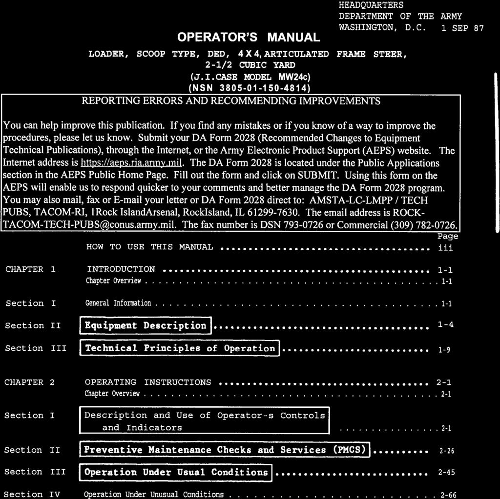
16 Section III APPENDIX A. APPENDIX B. APPENDIX C. APPENDIX D. Maintenance Procedures COMPONENTS OF END ITEM (COEI) AND BASIC ISSUE ITEMS (BII) LISTS ADDITIONAL AUTHORIZATION LIST (AAL) Page 3-35 A-1 B-1 C-1 D-1 ALPHABETICAL INDEX Index 1 ii
17 HOW TO USE THIS TECHNICAL MANUAL This manual is designed to help you operate and maintain the MW24C loader. It s divided into chapters, sections, and appendices. The chapters contain general information, operating procedures, and maintenance procedures. Chapters are divided into sections containing equipment description, principles of operation, description of operating controls and indicators, operating procedures, and troubleshooting and maintenance procedures. Appendices contain supplemental information which you require to operate and maintain the loader. Procedures in this manual tell you several things: how to perform your PMCS and how often how to start the loader including locations of all controls and indicators how to operate the loader safely and efficiently how to troubleshoot the loader how to maintain the loader All operating, troubleshooting, and maintenance procedures include illustrations to help you quickly locate the items on your equipment. To quickly locate data in this manual, let s say you want to find out the function and use of the hydraulic control levers mounted-to the right of your seat. There are two ways you can locate this information. a. Use the alphabetical index: (1) Look on the front cover index for ALPHABETICAL INDEX. (2) See that there is a black box drawn to the right of ALPHABETICAL INDEX. (3) Flip through the pages starting at the back of this manual stopping at the page that has a a black box in line with the box on the front cover index. This is the alphabetical index. (4) The alphabetical index contains subject matter listed in alphabetical sequence. Look up Hydraulic control levers or Loader controls. In some cases, subject matter may be listed in several different ways to help you locate the information. Across from these two entries you will find the page number (5) Turn to page 2-19 operation of the hydraulic (b) Use the front cover (1) Look on the front TROLS AND INDICATORS. (2) See that there is where you will find a short functional control levers. index: cover index for DESCRIPTION AND USE OF a black box drawn to the right of this description and OPERATOR S CONentry. iii
18 (3) Flip through the pages starting at the back of this manual stopping at the page that has a a black box in line with the box on the front cover index. This is the DESCRIPTION AND USE OF OPERATOR S CONTROLS AND INDICATORS, page 2-1. (4) Look in the section index and locate Loader Controls. It states the loader controls are provided in paragraph (5) Flipping through the pages, see that paragraph numbers are always located at the top of the left page. Now, go to paragraph 2-10 (page 2-21) to locate the information you want. This manual has been designed so that you can quickly locate data you are looking for. Either look in the ALPHABETICAL INDEX for the subject matter, refer to the front cover index, table of contents, chapter index, or section index to locate the data. iv
19 CHAPTER 1 INTRODUCTION CHAPTER OVERVIEW The purpose of this chapter is to acquaint you with the maintenance forms, records, and reports that you must maintain for the MW24C loader, to familiarize you with the purpose and capabilities of the vehicle, and to give you a brief description of its different systems and components. Section Index Title Page I General Information II Equipment Description III Technical Principles of Operation Section I. GENERAL INFORMATION Para Scope Maintenance Forms, and Records Hand Receipt (-HR) Manuals Reporting Equipment Improvement Recommendations (EIR S) Warranty Information Orientation List of Abbreviations NOTE The equipment described herein is non-metric and does not require metric common or special tools; therefore, metric units are not supplied. Tactical instructions for sake of clarity will also remain non-metric. a. Type of Manual. Operator s Manual, including operating, maintenance, and troubleshooting instructions. b. Model Number and Equipment Name. MW24C Diesel Engine Driven, 4 by 4, Articulated Frame Steer, 2-1/2 Cubic Yard Scoop Type Loader. 1-1
20 1-1. c. Purpose of Equipment. Loading trucks from stockpiles, stockpiling materiel, and excavating undisturbed and compacted soil. Unit also used as a clamshell to handle irregular shaped objects, as a dozer for general bulldozer work, and as a scraper MAINTENANCE FORMS,AND RECORDS Department of the Army forms and procedures used for equipment maintenance will be those prescribed by DA PAM , The Army Maintenance Management System (TAMMS) HAND RECEIPT ( HR) MANUALS This manual has a companion document with a TM number followed by -HR (which stands for Hand Receipt). The -HR consists of preprinted hand receipts (DA Form 2062) that list end item related equipment (i.e., COEI, BII, and AAL) you must account for. As an aid to property accountability, additional -HR manuals may be requisitioned as outlined in DA PAM REPORTING EQUIPMENT IMPROVEMENT RECOMMENDATIONS (EIR S) If your MW24C loader needs improvement, let us know. Send us an EIR. You, the user, are the only one who can tell us what you don t like about your equipment. Let us know why you don t like the design or performance. Put it on an SF 368 (Quality Deficiency Report). Mail it to us at: Commander, US Army Tank Automotive Command, ATTN: AMSTA-MV Warren, MI We ll send you a reply WARRANTY INFORMATION The MW24C loader is warranted by J.I.Case Company, Racine, Wisconsin for 15 months or 1500 hours of operation, whichever occurs first. Warranty starts on the date, found in block 23, DA Form in the logbook. Report all defects in material or workmanship to your supervisor who will take appropriate action through your organizational shop ORIENTATION The loader bucket is mounted at the front of the MW24C and the engine faces the rear. Controls for operating the bucket (lift arm, bucket tilt, clam) are located to the right when you are sitting in the operator-s seat. All references to right, left, front, or rear are from the viewpoint of the operator when he is sitting in the operator s seat. 1-2
21 1-7. LIST OF ABBREVIATIONS ABBREVIATION I DEFINITION ABBREVIATION I DEFINITION A AAL AMP AR ATTN B BII BRT. B.O. C COEI COMPT CONT CONV D DA db EIR etc. After Authorized allowance list Amperes Army regulations Attention Before Basic issue items Bright Black out Celsius Components of end items Compartment Continued Converter Daily Department of the Army Decibel Equipment improvement recommendations Etcetera (unspecified additional things ) F H HR L lb-ft M MI MO MPH N NEUT. Para PMC S PRESS psi R rpm SER. TEMP TM w Fahrenheit High (forward) Hand receipt Low (forward) Pounds feet Monthly Michigan Missouri Miles per hour Neutral Neutral Paragraph Preventive maintenance checks and services Pressure Pounds per square inch Reverse Revolutions per minute Service Temperature Technical Manual Weekly 1-3
22 Section II. EQUIPMENT DESCRIPTION Para Equipment Characteristics, Capabilities, and Features Location and Description of Major Components Differences Between Models Equipment Data EQUIPMENT CHARACTERISTICS, CAPABILITIES, AND FEATURES a. Purpose of MW24C Loader. Loading trucks and railcars from stockpiles, stockpiling materiel, and excavating undisturbed and compacted soil. Unit also used as a clamshell to handle irregular shaped objects, as a dozer for general bulldozer work, and as a scraper. b. Capabilities and Features. (1) Two and one-half yard capacity bucket. (2) Operates over rough terrain. (3) Four speed ranges in forward; two speed ranges in reverse. (4) Declutch pedal disengages transmission during loader operation to provide maximum hydraulic power when needed. (5) Diesel engine driven. (6) Power steering. (7) Power assisted air over hydraulic brakes. (8) Enclosed operator s compartment. (9) Auxiliary steering automatically cuts-in if primary steering is disabled. (10) Bucket height control to automatically stop loader lift arms at a preselected dump height. (11) Bucket return-to-dig control to automatically return bucket to preselected position. (12) Four-in-one bucket used as a scraper, blade, clamshell, or standard bucket. (13) Ford depths up to 30 inches. (14) Collapsible steering wheel for air transport LOCATION AND DESCRIPTION OF MAJOR COMPONENTS ENGINE. J.I.Case Model A504BD Diesel engine having a displacement of 504 cubic inches. Accessories mounted on and considered a part of the engine include the alternator, air compressor, starting motor, fuel injection pump, and fuel filters. FUEL SYSTEM. Consists of fuel injectors, fuel injection pump, electric fuel pump, air cleaner, fuel filters, and cold start kit. EXHAUST SYSTEM. Consists of muffler and exhaust pipe. Muffler mounted on top of engine. COOLING SYSTEM. Includes radiator mounted in rear of loader, thermostat and housing, engine driven water pump, and fan. 1-4
23 ELECTRICAL SYSTEM. 24 volt, negative ground. Includes engine driven alternator, starter motor, instrument panels, light system, and two 12 volt batteries connected in series. BRAKES. Disk brakes, air over hydraulic. Air actuated drum type parking brake located on transmission output shaft. STEERING SYSTEM. Consists of steering wheel, steering column and gear, and two steering cylinders. Power assist provided by hydraulic pump mounted on and driven by transmission. Also includes auxiliary steering system. 1-5
24 FRAME AND TOWING ATTACHMENTS. Two section frame consisting of front and rear chassis; drawbar pin located at rear of loader. SIGNALING DEVICES. Consists of back-up alarm and turn signals. Back-up alarm located at rear of loader; sounds when transmission is shifted into reverse. Turn signals located at top of cab; turn signal switch mounted on steering column. TRANSMISSION AND DRIVE SHAFTS. Four speeds in forward and two speeds in reverse. Has declutch feature which permits neutralizing transmission. Three drive shafts used to transmit power to front and rear axles. AXLES AND WHEELS. Standard planetary axles; pneumatic tires. CAB. Fully enclosed and removable for shipment purposes windows, and front and rear windshields. when necessary. With doors, ACCESSORIES. Includes air horn and control valve, windshield washer and wiper, outside mirrors, heater, and fan defrosters. HYDRAULIC SYSTEM. Consists of hydraulic main pump assembly/steering pump, control valve assembly, hydraulic cylinders (lift arm, bucket tilt, and clam), hydraulic reservoir, and hydraulic filter. EARTHMOVING COMPONENTS. bucket assembly. Includes bucket lift arms and pivot assemblies and loader DIFFERENCES BETWEEN MODELS There are no differences between models of the MW24C loader EQUIPMENT DATA Manufacturer J.I. Case Model MW24C Dimensions and Weight Overall operating height (A) feet, 1-1/2 inches Dump clearance at maximum height, 45 degrees dump (B) feet Dump reach at maximum height, 45 degrees dump (C) feet, 1 inch Dump reach at 7 feet dump height, 45 degrees dump (D) feet, 5 inches Height to bucket hinge pin (E) feet, 2-1/2 inches Maximum shipping height (F) feet, 10-1/2 inches Overall length, bucket on ground (G) feet, 5-1/2 inches Overall width l /2 inches Wheel base (H) feet, 1-1/2 inches Tire tread inches Ground clearance (I) inches Height to top of steering wheel (J) /2 inches Overall height without cab /2 inches Width overtires inches 1-6
25 1-11. EQUIPMENT DATA (CONT) Dimensions and Weight (Continued) Total weight 25,900 pounds Front axle weight 12,750 pounds Rear axle weight ,150 pounds Capacities Cooling system gallons Cold weather protection To zero degree gallons ethylene glycol To -20 degrees F gallons ethylene glycol To -40 degrees F gallons ethylene glycol Fuel tank gallons Engine crankcase quarts refill; 20 quarts with filter change Transmission gallons refill; 9 gallons total system capacity Axles (each) Front differential carrier quarts Rear differential carrier quarts Planetary ends (each) 3.5 quarts Hydraulic reservoir gallons refill; 29 gallons total system capacity 1-7
26 1-11. EQUIPMENT DATA (CONT) Loader bucket Width inches Rated capacity /2 yards Tires Size X 25 Air pressure psi Performance speeds (MPH) Forward 1st low range nd low range rd high range th high range Reverse 1st nd Military Load Classification Empty Loaded
27 Section III. TECHNICAL PRINCIPLES OF OPERATION Para Fuel System Cooling System Electrical System Vehicle Lights a Switches and Circuit Breakers. 1-14b Warning Indicators c Gages d Slave Receptacle and Hourmeter/Tachometer e Batteries and Cables f Wiring Harnesses g Para Transmission and Drive Shafts Transmission Controls a Drive Shafts b Brakes Steering System Frame and Towing Attachments Cab 1-19 Accessories Hydraulic System Signaling Devices Earthmoving Components FUELSYSTEM AIR PRECLEANER AND CLEANER. Removes dust and dirt from air before application to engine through intake manifold. Metal shell houses replaceable inner and outer filter elements. Squeezing ends of vacuator valve (located at bottom of metal shell) releases dust and dirt from air cleaner housing. AIR CLEANER RESTRICTION INDICATOR. Indicates restrict ion of air flow through air cleaner due to dirty or clogged filter elements. Filter elements servicing is required when red signal within indicator is in full view. After servicing filter elements, indicator is reset by depressing button on top of indicator. FUEL TANK AND FUEL FILLER. Fuel tank holds approximately 58 gallons of Diesel fuel; located at rear of loader. Fuel filler neck and removable cap located at right rear of loader. Accessible by unlocking and removing right rear side panel. Drain plug located at bottom of fuel tank. COLD START SWITCH. When depressed, injects ether start ing fluid into intake manifold. This switch is used to start engine in cold weather only. It operates when ignition key switch is in start position and starter is cranking. 1-9
28 1-12. FUEL SYSTEM (CONT) ACCELERATOR PEDAL. Depressing pedal with foot increases fuel flow and engine speed. Releasing pedal decreases fuel flow and engine speed. Pedal is spring loaded to return to low speed position when released. FUEL LEVEL GAGE. Electrically operated meter type. With ignition key switch in ON position, FUEL LEVEL gage indicates quantity of fuel remaining in fuel tank. FUEL SHUT OFF CONTROL (ENGINE STOP). Cable connected to fuel injection pump fuel shut off lever. When pulled out, fuel is unable to enter fuel injection pump effectively stopping engine operation. FUEL INJECTOR LINES. Fuel is routed to six fuel injectors from fuel injection pump through rigid metal tubes. Return (leak-off) fuel is routed through rigid metal tubes interconnecting each fuel injector back to fuel injection pump COOLING SYSTEM RADIATOR. Located at rear of loader. Engine coolant circulated through radiator giving up its heat to air stream developed by belt driven fan. Cooled coolant drawn from bottom of radiator by water pump and discharged into lower part of cylinder block. Radiator has oil cooler built into its bottom for cooling transmission hydraulic oil. Radiator cap accessible by unlocking and raising access panel located at top rear of loader. WATER TEMP GAGE. Indicates engine coolant temperature. Normal operating temperature is in green zone. 1-10
29 1-14. ELECTRICAL SYSTEM a. Vehicle Lights. VEHICLE LIGHTS SWITCH. Contains three separate switch vehicle lights. Ignition key switch must be turned to operate. sections used to control all on position for this switch to 1-11
30 1-14. ELECTRICAL SYSTEM (CONT) a. Vehicle Lights (Cont). FLOOD LIGHTS SWITCH. Independently turn front and rear flood lights on and off. Vehicle lights switch must be in SER. DRIVE position for this switch to operate. BLACK OUT DRIVING LAMP. Mounted on left front fender. Provides forward black out illumination during tactical operations. Controlled by vehicle lights switch. FRONT FLOOD LAMPS. Two sealed beam type lamps mounted on mounting brackets at front left and right sides of loader. Illuminate work area in front of loader. Turned on and off with FLOOD LIGHTS switch. DRIVING LAMPS. Two sealed beam type lamps mounted above flood lamps at left and right sides of loader. Illuminate area in front of loader for driving at night. REAR FLOOD LAMPS. Two sealed beam type lamps mounted on mounting brackets at rear left and right sides of loader within radiator guard and behind radiator grille. Illuminate work area in rear of loader. Turned on and off with FLOOD LIGHTS switch. STOP AND TAIL LIGHTS. Two light assemblies mounted on brackets within radiator guard, behind radiator grille. Includes incandescent lamp and red plastic lens. Tail lights turned on by vehicle lights switch. Stop lights normally off; turned on by pressing brake treadle valve or declutch treadle valve. BLACK OUT STOP LIGHT-TAIL LIGHT. Two light assemblies mounted in protective metal housings within radiator guard, behind radiator grille. Each assembly contains two incandescent lamps. Provide stop light and tail light illumination during tactical operations. Tail lights turned on and off by vehicle lights switch. Stop lights are normally off; turned on by pressing brake treadle valve or declutch treadle valve. b. Switches and Circuit Breakers. 1-12
31 IGNITION KEY SWITCH. Four position key switch controls power to all vehicle electrical circuits. DIMMER COMPT LIGHTS CONTROL. Rheostat. Controls brightness of left instrument panel cluster illumination lamps, voltmeter gage illumination lamp, and cab dome light. 5 AMP CIRCUIT BREAKER (A). Resettable circuit breaker. Protects auxiliary steering circuit, air brake pressure switch and buzzer, gages, warning lights, and voltmeter, cab relay solenoid, and electric fuel pump. 5 AMP CIRCUIT BREAKER (B). Resettable circuit breaker. Protects return-to-dig and bucket height control circuits. c. Warning Indicators. BRAKE ENGAGED INDICATOR. When lit, indicates either parking brake is engaged or brake system air pressure is too low for safe loader operation. ENGINE OIL PRESS INDICATOR. When lit with engine operating, indicates engine oil pressure is too low and damage to engine will occur if you continue to operate engine. CLUTCH PRESS INDICATOR. Will light if declutch treadle valve is pressed with engine operating, if transmission converter oil pressure is too low, or if parking brake is engaged. If transmission converter oil pressure is too low, continued loader operation will damage transmission. AIR PRESSURE WARNING ALARM. Sounds when brake system air pressure is too low for safe loader operation. indicates hydraulic filters (steering and hy- HYDRAULIC FILTER INDICATOR. When lit, draulic system) require replacement. AUXILIARY STEERING BUZZER AND INDICATOR. Buzzer sounds and indicator lights warning operator that hydraulic pump has failed and auxiliary steering system has been energized and is now operating. If this happens, you must stop loader operation and notify next higher maintenance level. 1-13


32 1-14. CONV TEMP GAGE. Indicates operating temperature of transmission torque converter. Normal temperature is in green area of gage. AIR PRESS GAGE. Indicates brake system air pressure. Air pressure is normal when pointer is in green area of gage. FUEL LEVEL GAGE. Indicates amount of fuel in fuel tank. WATER TEMP GAGE. Indicates temperature of engine coolant. Coolant temperature is normal when pointer is in green area of gage. VOLTMETER GAGE. Indicates voltage level of batteries. Voltage is normal when pointer indicates 24 volts 22 volts with ignition key switch in on position. 1-14
33 f. Batteries and Cables. BATTERY CABLES. Six cables used. Battery interconnecting cable connects first battery negative terminal to second battery positive terminal. Ground cables connected between second battery negative post, battery disconnect switch, and negative terminal of slave receptacle. A separate ground cable connects from output of battery disconnect switch to the starter motor terminal. Ground cables connected at battery terminal by terminal lug. Positive cable connected between first battery positive terminal, starter solenoid, and slave receptacle positive terminal. Positive cables connected at battery terminal by terminal lug. BATTERY DISCONNECT SWITCH. Isolates ground from electrical system when turned off. Slave receptacle remains connected to negative battery terminal. Battery disconnect switch provides ground to the electrical system when energized. Change
34 1-14. ELECTRICAL SYSTEM (CONT) g. Wiring Harnesses. FRONT WIRING HARNESS. Interconnects front driving lamps and flood lamps, black out driving lamps, left and right instrument panels, turn signal lamps, return-to-dig circuit, bucket height control circuit, control valve solenoids, and hydraulic filter switch. Multi pin connector mates with associated connector on rear harness. REAR WIRING HARNESS. Interconnects engine and transmission sending units, rear flood lamps, stop and tail lights, black out stop light-tail light, back-up alarm, and starter and cab relay solenoids and associated circuit breakers. Multi-pin connector mates with associated connector on front harness. BLACKOUT LIGHTS WIRING HARNESS. Interconnects driving lamp mounted on left front fender and mounted at rear of loader. Connection between block-type connectors. front wiring harness to blackout blackout stop lights-tail lights wiring harnesses accomplished by CAB UPPER WIRING HARNESS. Interconnects cab console wiring harness to cab dome light, defroster fans, defogger, and turn signal lamp assemblies. Cab upper wiring harness connector is mounted on cab wall just behind cab console. Connection between wiring harnesses accomplished by block type connectors. CAB LOWER WIRING HARNESS. Interconnects front wiring harness to cab console wiring harness and to circuit breakers mounted on cab switch panel. Connection between wiring harnesses accomplished by block-type connectors. CAB CONSOLE WIRING HARNESS. Interconnects cab upper wiring harness to cab lower wiring harness and switches mounted on cab switch panel. Connection to cab upper wiring harness accomplished by block-type connector; connection to cab lower wiring harness accomplished by bullet terminals. 1-16

35 1-15. TRANSMISSION AND DRIVE SHAFTS a. Transmission Controls. TRANSMISSION CONTROL LEVER. Selects one of four positions: low range forward, high range forward, neutral, and low range reverse. DECLUTCH TREADLE VALVE. Applies service brakes, lights stop lights at rear of loader, disengages transmission, and lights CLUTCH PRESS indicator. Used to disengage transmission to provide maximum hydraulic power for loader operation. b. Drive Shafts. FRONT DRIVE SHAFT. Connected between center drive shaft and front axle. Connected to front axle yoke by universal joint and to center drive shaft by yoke with internal splines. Rear of front drive shaft supported by a bearing. CENTER DRIVE SHAFT. Connected between transmission output shaft and front drive shaft. Connection accomplished by universal joints. REAR DRIVE SHAFT. Connected between transmission output shaft and rear axle by universal joints. 1-17
36 1-16. BRAKES PARKING BRAKE VALVE. Controls flow of air to actuator. Pushing knob in applies air pressure to actuator in turn releasing parking brake. Pulling knob out releases air pressure applied to actuator. Large spring in actuator then moves piston causing linkage and lever in parking brake to force brake shoes against brake drum. ACTUATOR. Located left side of loader. Includes large spring and piston. When air pressure applied by parking brake valve, it pushes against piston and compresses spring in turn releasing parking brake. When air pressure released, large spring forces piston to move and apply parking brake. PARKING BRAKE. Mounted on transmission output shaft. Drum type parking brake prevents axles and wheels from rotating when applied. BRAKE TREADLE VALVE. Depressing treadle valve applies air pressure to brake actuators. This in turn applies hydraulic pressure to brake calipers mounted on each wheel end and applying brake pads to disks mounted on wheel ends to stop loader. Brake actuators consist of an air chamber and hydraulic master cylinder. Also turns on stop or black out stop lights as determined by position of vehicle lights switch. Brake system is air over hydraulic. SERVICE BRAKES. Disk brakes mounted on each wheel end. AIR RESERVOIR. Mounted at right side of loader. Air from air compressor routed to and stored in air reservoir until required by air system components. 1-18
37 1-17. STEERING SYSTEM STEERING WHEEL. Connected to steering column and steering gear. Steering column and steering gear control flow of hydraulic oil to and from steering cylinder assemblies. Power assist provided by hydraulic pump mounted on transmission for reduced steering wheel turning effort when engine is running. Collapsible steering wheel column allows for reduction in height for transport operations by depressing button in center of steering wheel under cover. STEERING CYLINDER ASSEMBLIES. Two hydraulic cylinders, one mounted on each side of loader. Cylinder housings attached to front chassis and cylinder rods attached to rear chassis. Cylinder rods extend or retract as steering wheel is turned, forcing front chassis to pivot about chassis spindle assemblies. CHASSIS SPINDLE ASSEMBLIES. Heavy duty spindles mounted in thrust bearings and located at top and bottom of chassis connection points. Secure front chassis to rear chassis and allow front chassis to pivot and steer loader. AUXILIARY STEERING MOTOR AND PUMP. Mounted on left side of loader. Provides emergency hydraulic power for steering loader if hydraulic pump fails. Consists of hydraulic pump driven by electric motor. Electric motor automatically operates if main hydraulic pump fails and auxiliary steering warning buzzer sounds when motor turns on. If you crank starter motor with SHUT OFF control pulled out then release ignition key switch, you will hear auxiliary steering motor and pump start to operate. If this happens, turn ignition key switch to off position to stop auxiliary steering motor and pump. 1-19

38 1-18. FRAME AND TOWING ATTACHMENTS ENGINE SIDE PANELS. Constructed of sheet metal. Secured to rear chassis by latches: two for each panel. Provide access to engine compartment. DRAWBAR PIN. Constructed of heavy steel. Provides means of attaching pintle hook or drawbar for towing loader or using loader as tow vehicle. TRUNNION ASSEMBLY. Rear axle mounted on trunnion assembly providing rear axle oscillation. Allows rear chassis to pivot when operating over rough terrain. TRANSPORT/SERVICE LINK. Constructed of heavy gage steel. Must be in operating position during loader operation. Prevents loader from pivoting therefore no steering control when in engaged position. Must be in engaged position when personnel are working in area between front and rear chassis, when loader is being airlifted or transported, or loader is jacked up. FRONT ACCESS DOOR. Constructed of sheet metal. Provides access to hydraulic reservoir and windshield washer reservoir. Hydraulic reservoir sight gage located just below access door. 1-20
39 1-19. CAB WINDSHIELDS AND SIDE WINDOWS. Front windshield, rear windshields, and two side windows provide operator with a 360 degree field of vision. DOOR ASSEMBLIES. Two door assemblies. Each door assembly consists of an upper and a lower door assembly. Upper door assembly can be unlatched from lower door assembly and latched in full open position. Upper door assembly includes glazing. SLINGING EYES. Two slinging eyes located at top of cab to aid in cab removal and installation. 1-21
40 1-20. ACCESSORIES WINDSHIELD WASHER. Front windshield washer. Air actuated. Nozzle mounted just below front windshield. Depressing control located on left instrument panel applies air pressure to fluid reservoir in turn forcing fluid from reservoir through hose to spray out nozzle onto windshield. OUTSIDE MIRRORS. One mounted on each side of cab. Easily adjusted by operator. 1-22
41 CAB INSIDE MIRROR. Mounted inside cab, right side. WINDSHIELD WIPER AND MOTOR. Electric motor driven wiper. Wiper motor mounted directly behind wiper arm. DEFROSTER ASSEMBLY. Mounted at cab ceiling. clear windshield of fog. Directs air over front windshield to CAB DOME LIGHT. Located behind defogger assembly. Includes on-off switch. provides illumination for cab. Brightness controlled by DIMMER COMPT LIGHTS control mounted on right instrument panel and vehicle lights switch auxiliary switch. Vehicle lights switch main switch and auxiliary switch must be in any position other than OFF for this light to operate. DEFOGGER FANS. Two fans. Mounted above and to sides of rear windshield. Each fan includes LOW-OFF-HIGH switch and is directionally adjustable to direct airflow over rear windshields. CAB HEATER. Located to left of operator s seat. Utilizes heat from engine coolant to heat cab. Includes electric motor driven fan. CONSOLE SWITCH PANEL. Contains switches and circuit breakers for defroster, heater fan, and front wiper circuits. AIR HORN. Air horn valve located on cab deck to left of declutch treadle valve. Depressing valve routes air Pressure to air horn causing diaphragm to vibrate sounding air horn. Air horn located on left side of front chassis beneath cab HYDRAULIC SYSTEM 1-23
42 1-21 HYDRAULIC SYSTEM (CONT) RETURN-TO-DIG CONTROL. Returns bucket to digging position after it has been dumped. Operator adjusted control. BUCKET HEIGHT CONTROL. Automatically stops loader lift arms at an operator selected dump height. BUCKET TILT CYLINDER ASSEMBLIES. Two used. dumping, etc. Position bucket for digging, scraping, LIFT ARM CYLINDER ASSEMBLIES. Two used. Raise or lower bucket. BUCKET CLAMSHELL CYLINDER ASSEMBLIES. Two used. Open or close bucket clamshell. LIFT ARM CONTROL LEVER. Controls raising and lowering of bucket. BUCKET CONTROL LEVER. Controls dumping of bucket and tilting bucket for carrying a load. CLAM CONTROL LEVER. Controls opening and closing of bucket clamshell. Placing control lever in HOLD position will cause bucket clamshell to hold its position. 1-24

43 HYDRAULIC RESERVOIR. Located behind front access door. Oil filler cap located at top of reservoir. SIGHT GAGE. Located at front of loader. Oil level must be seen in sight gage. If oil level is not seen, hydraulic oil must be added SIGNALING DEVICES BACK-UP ALARM. Electrically operated alarm located at rear of loader behind radiator grille. Sounds distinctive warning whenever transmission control lever is placed in reverse (R) position. Ignition key switch must be turned to on position before backup alarm will sound. 1-25
44 1-22. SIGNALING DEVICES (CONT) TURN SIGNALS. Two turn signal lamps located at top left and right of cab. Turn signal lever mounted on steering column. Moving turn signal lever away from you causes left turn signal lamp to flash on and off indicating left turn. Lever must be manually returned to center position after turn is completed. Moving lever towards you causes right turn signal lamp to flash on and off indicating right turn EARTHMOVING COMPONENTS BUCKET LIFT ARMS AND PIVOT ASSEMBLIES. Provides the means of raising/lowering bucket and tilting bucket. LOADER BUCKET ASSEMBLY. Includes bucket and clam. Bucket cutting edge consists of three cutting edges bolted to bucket. Nine tooth assemblies bolted to clam cutting edge. Clam cutting edge welded to clam. 1-26
45 CHAPTER 2 OPERATING INSTRUCTIONS CHAPTER OVERVIEW The purpose of this chapter is to familiarize you with the equipment so that you can operate it safely, efficiently, and effectively. Index Section Title Page I Description and Use of Operator's Controls and Indicators II Preventive Maintenance Checks and Services (PMCS) III Operation Under Usual Conditions IV Operation Under Unusual Conditions Section I. DESCRIPTION AND USE OF OPERATOR S CONTROLS AND INDICATORS Instrument Panels Right Instrument Panel Left Instrument Panel Console Switch Panel Switches and Control Circuit Breakers Transmission Controls Brake and Throttle Controls Turn Signals and Flasher Para a 2-1b a 2-2b Rear Windshield Defogger Fans.... Dome Light Switch Upper and Lower Door Latches..... Operator-s Seat Loader Controls Externally Mounted Controls and Indicators Other Operator s Controls and Indicators Para
46 12-1. INSTRUMENT PANELS a. Right Instrument Panel. (1) Circuit Breakers. 5 AMP CIRCUIT BREAKER Resettable circuit breaker; reset by pressing button. Button pops out when circuit breaker blows. Protects HYDRAULIC FILTER warning indicator and switches and bucket height and return-to-dig control circuits. 5 AMP CIRCUIT BREAKER Resettable circuit breaker; reset by pressing button. Button pops out when circuit breaker blows. Protects auxiliary steering control circuit, air brake pressure switch and buzzer, gages, warning indicators located on left instrument panel, cab relay solenoid, and electric fuel pump. 2-2
47 2-1. INSTRUMENT PANELS (CONT) a. Right Instrument Panel (Cont). (2) Engine Switches. Four position key switch. IGNITION KEY SWITCH First unmarked position (key turned counterclockwise): Applies power to: vehicle lights switch enabling lights to be turned on; auxiliary steering control circuit; low air pressure warning circuit sounding warning buzzer; gages; and left instrument panel warning indicators turning them on; and electric fuel pump. Off position (key straight): Electrical system off. On position (key turned to first clockwise position): Applies power to: vehicle lights switch enabling lights to be turned on; auxiliary steering control circuit; low air pressure warning circuit sounding warning buzzer; gages; left instrument panel warning indicators turning them on; electric fuel pump; and return-to-dig and bucket height control circuits. Start position (key turned to extreme clockwise position, spring loaded return): Applies power to return-to-dig and bucket height control circuits; cranks starter motor to start engine, momentarily turns on HY- DRAULIC FILTER warning indicator, and applies power to COLD START switch. COLD START SWITCH Aids in starting engine when temperature is 40 degrees or less. Starting fluid is toxic and highly flammable. Use caution when handling. Pushbutton switch: Operates only when ignition key switch is cranking starter. Pressing switch energizes solenoid valve installed on cold start container allowing starting fluid to enter intake manifold. 2-3
48 2-1. INSTRUMENT PANELS (CONT) a. Right Instrument Panel (Cont). (3) Flood Lights Switch and Warning Indicator. FLOOD LIGHTS SWITCH Two position toggle switch. On position (right position): Turns on front and rear flood lamps. NOTE Main switch on vehicle lights switch must be in SER. DRIVE position for this switch to operate. Off position (left position): Turns off front and rear flood lamps. HYDRAULIC FILTER WARNING INDICATOR Indicator light. Turns on momentarily when first starting engine indicating bulb is okay. During operation, turns on indicating hydraulic filters are clogged and require replacement. 2-4
49 2-1. INSTRUMENT PANELS (CONT) a. Right Instrument Panel (Cont). (4) Vehicle Lights Switch. Five position switch section. MAIN SWITCH B.O. MARKER: Black out tail lights lit. Stoplights will light when brake treadle valve is pressed. B.O. DRIVE: Black out tail lights and blackout drivinglamp lit. Stop lights will lightwhenbrake treadle valve is pressed. OFF (Unmarked): All lamps off. STOP LIGHT Stop lights will light when brake treadle valve is depressed. Turn signals can be turned on. SER DRIVE: Tail lights and front driving lamps lit. Stop lights will light when brake treadle valve is pressed. Turn signals and flood lights can be turned on. NOTE Ignition key switch must be in extreme counterclockwise position or on position for vehicle lights switch to operate. AUXILIARY SWITCH Four position switch section. PANEL BRT.: Gage lights brightly lit and cab dome light can be turned on. DIM: Gage lights dimly lit and cab dome light can be turned on. OFF (unmarked): Panel and tail lights off. PARK: Service tail lights lit (main switch in SER DRIVE position) and gage lights dimly lit and cab dome light can be turned on. Black out tail lights lit (main switch in B.O. DRIVE or B.O. MARKER position). NOTE Main switch section must be in any position other than OFF for auxiliary switch section to operate. MECHANICAL LOCK Spring loaded switch section. LOCK (unmarked): Main switch can only be placed in B.O. MARKER position; all other positions locked out. UNLOCKED: Enables main switch to be placed in B.O. DRIVE, STOP LIGHT, or SER DRIVE POSITION. To operate, hold lever in UNLOCK position and move main switch lever to desired position. 2-5
50 2-1. INSTRUMENT PANELS (CONT) a. Right Instrument Panel (Cont). (5) Other Controls and Indicator. SHUT OFF CONTROL Fuel shut off control; engine stop. Cable connected to fuel injection pump fuel shut off lever. Pull out to stop engine. After engine has stopped, push control in. Control must be pushed in all the way in order to start engine. PARKING BRAKE CONTROL Pull on, push off control. Applies parking brake. Pulling knob out applies parking brake. Pushing knob in releases parking brake. When parking brake applied, BRAKE ENGAGED and CLUTCH PRESS warning indicators on left instrument panel will be lit. DIMMER COMPT LIGHTS CONTROL Rheostat control. Controls brightness of gage lights and cab dome light (auxiliary switch in any position other than OFF). Turn control to extreme counterclockwise position for brightly lit lights. Turn control clockwise to decrease brightness. Extreme clockwise position turns lights off. AIR PRESSURE WARNING ALARM Audible alarm. Sounds when engine is first started until air pressure reaches approximately 65 psi at which time it will turn off. During operation, sounds to warn operator that there is not enough air pressure to continue operating loader safely. 2-6
51 2-1. INSTRUMENT PANELS (CONT) b. Left Instrument Panel. (1) Warning Indicators. BRAKE ENGAGED Warning indicator light. Turns on indicating there is low or no air pressure in brake system. Will also turn on when parking brake control is pulled out indicating parking brake is applied. OIL PRESS Warning indicator light. Turns on indicating there is no oil pressure or low oil pressure in the engine. Will also turn on if engine is stopped and ignition key switch is turned to on position indicating bulb is okay. If this indicator turns on when engine is running, turn engine off and check engine oil level. If engine oil level is okay, do not start engine; notify organizational level maintenance. AUXILIARY STEERING Audible warning indicator and light. Buzzer sounds and lamp turns on indicating steering system is not operating and that auxiliary steering system is operating. If buzzer sounds and/or lamp turns on, stop loader immediately and notify organizational maintenance. NOTE The auxiliary steering system is only used for a short period of time if steering system doesn t operate. When actuated, this system will allow you to steer the loader with hydraulic power until the loader can be stopped. After stopping loader, be sure you turn ignition key switch to off position and apply parking brake as soon as possible. If you fail to do this, you will cause damage to auxiliary steering electric motor and discharge the batteries. CLUTCH PRESS Warning indicator light. Turns on indicating there is no oil pressure or low oil pressure in the transmission torque converter. Will also turn on if engine is stopped and ignition key switch is turned to on position indicating bulb is okay, if engine is running and declutch treadle valve is pressed, and if parking brake is applied. If this indicator turns on with engine running and declutch treadle valve is not depressed, and stays on for more than 60 seconds, stop engine and notify organizational maintenance. 2-7
52 2-1. INSTRUMENT PANELS (CONT) b. Left Instrument Panel. (2) Gages. CONV TEMP GAGE Indicates transmission torque converter temperature. Normal operating temperature indication is in green area of gage. If gage pointer goes into red area, select a lower transmission speed. If pointer remains in red area, stop operation, move transmission control lever in neutral (N) position, and run engine at full throttle. If this does not reduce temperature indication, stop engine and check transmission oil level. If oil level is okay, check radiator for obstructions. AIR PRESS GAGE Indicates brake system air pressure. Normal air pressure indicated when pointer is in green area of gage. If air pressure decreases and pointer goes into red area, warning buzzer will sound alerting you of this condition. If air pressure continues to decrease, parking brake will automatically engage. FUEL LEVEL GAGE Indicates amount of fuel in fuel tank. VOLTMETER GAGE Indicates voltage level of batteries. Voltage is normal when pointer indicates 24 volts. If pointer indicates below 22 volts, battery charge is too low for continued operation or alternator is not charging batteries. If pointer is indicating above 30 volts and you know that batteries were not weak, alternator is over charging batteries. If this condition continues, damage to batteries will result. Report these problems to organizational maintenance. WATER TEMP GAGE Indicates temperature of coolant in engine cooling system. Normal coolant temperature indicated when gage pointer is in green area. If pointer goes into red area, stop engine and check radiator coolant level or for radiator obstructions. 2-8
53 2-1. INSTRUMENT PANELS (CONT) b. Left Instrument Panel. (3) Windshield Washer Control. WINDSHIELD WASHER CONTROL Push on control. Controls flow of washer solvent sprayed on windshield. Push control in to spray washer solvent on windshield; release to stop spray. 2-9
54 2-2. CONSOLE SWITCH PANEL a. Switches and Control. DEFROSTER SWITCH Two position rotary switch. ON: Turns on defroster motor located above front windshield to defog front windshield. OFF: Turns off defroster motor. HEATER FAN SWITCH Three position pull on - push off switch. OUT - LOW (switch shaft pulled completely out): Heater fan operates at low speed. Heater fan draws air over heater core where it is heated then expelled out heater console. MID - HI (switch shaft pulled out to first detent position): Heater fan operates at high speed. IN - off. OFF (switch shaft pushed in): Heater fan FRONT WIPER SWITCH Three position rotary switch. H (high): Front windshield wiper motor operates at high speed. L (low): Front windshield wiper motor operates at low speed. OFF: Front windshield wiper motor off. HEAT CONTROL Rotary control. Clockwise rotation increase; counterclockwise rotation decrease. Controls flow of engine cooling system coolant through heater core. For maximum heat, turn control completely clockwise to WARM position. To turn off heat, turn control to OFF position. WARM: Valve completely open allowing maximum flow of engine coolant through heater core. OFF: Valve closed; flow of engine coolant through heater core blocked. 2-10
55 2-2. CONSOLE SWITCH PANEL (CONT) b. Circuit Breakers. 6 AMP CIRCUIT BREAKER Resettable circuit breaker; reset by pressing button. Button pops out when circuit breaker blows. Protects defroster and defogger fans circuits. 3 AMP CIRCUIT BREAKER Resettable circuit breaker; reset by pressing button. Button pops out when circuit breaker blows. Protects front windshield wiper circuit. 3 AMP CIRCUIT BREAKER Resettable circuit breaker; reset by pressing button. Button pops out when circuit breaker blows. Protects heater fan circuit. 2-11
56 2-3. TRANSMISSION CONTROLS TRANSMISSION CONTROL LEVER Selects direction and drive speeds (in forward). Rearmost position is reverse (R), next position is neutral (N), third position is low range forward (F), and forwardmost position is high range forward (H). To go from low range forward (F) to high range forward (H), you must lift control lever up then push it forward. When control lever is in reverse (R) position, back-up alarm at rear of loader will sound. Control lever must be in neutral (N) to start engine. DECLUTCH TREADLE VALVE Neutralizes transmission, applies service brakes and turns on stop lights and CLUTCH PRESS warning indicator. Use to provide maximum engine power to increase loader hydraulic system power for raising bucket. Move loader into stockpile. When engine speed decreases, press declutch treadle valve to disengage transmission, then press accelerator pedal to increase engine rpm providing maximum engine power to loader hydraulic system to quickly raise bucket. 2-12

57 2-4. BRAKE AND THROTTLE CONTROLS STEERING WHEEL Steers loader by moving front chassis on pivot pins. Turn clockwise for right turn. Turn counterclockwise for left turn. Do not depress button in center of steering wheel; it is not a horn button. Depressing this button causes steering wheel to collapse for shipment purposes. If you depress this button while operating loader, steering wheel will collapse. Your fingers could be crushed between steering wheel and windshield wiper motor bracket. ACCELERATOR PEDAL Increases/decreases engine speed. Depressing pedal increases engine rpm; releasing pedal decreases engine rpm. Actuates air horn. HORN VALVE Press button with foot to sound air horn. SERVICE BRAKE TREADLE VALVE Applies service brakes. Depress treadle valve to apply brakes. With vehicle lights switch main switch in any position other than OFF, stop lights will turn on. 2-13
58 2-5. TURN SIG NALS AND FLASHER TURN SIGNAL SWITCH Three position switch with indicator. Lever in forward position (away from you): Lamp assembly mounted at top left of cab flashes on and off signaling left turn. Bulb located in turn signal switch will also flash on and off. You must return lever to center position after you have completed the turn to stop lamp assembly from flashing. Lever in center position: Turn signals off. Lever in rearward position (toward you): Lamp assembly mounted at top right of cab flashes on and off signaling right turn. Bulb located in turn signal switch will also flash on and off. You must return lever to center position after you have completed the turn to stop lamp assembly from flashing. Pull on control. HAZARD CONTROL On (pull out): Pull control out to the right. Lamp assemblies mounted at top left and right of cab will flash on and off. Bulb located in turn signal switch will also flash on and off. Off: Turn off flashing lamp assemblies by pulling turn signal switch lever down or up. 2-14

59 2-6. REAR WINDSHIELD DEFOGGER FANS ON-OFF SWITCH Three position rocker switch. LOW: Fan motor operates at low speed. OFF: Turns off power to fan motor. HIGH: Fan motor operates at high speed. To adjust position of defogger fans, grasp motor with your hands and firmly move into desired position. Before adjusting position of defogger fan, be sure it is not operating. Failure to do so could cause serious injury to fingers or hand by rotating fan blade. If you injure your fingers or hand, obtain medical aid immediately. 2-15
60 2-7. DOME LIGHT SWITCH] ON-OFF SWITCH Two position rocker switch. ON: Turns cab dome light on. Vehicle lights switch main and auxiliary switches must be in any position other than OFF for this switch to operate dome light. Brightness of cab dome light controlled by DIMMER COMPT LIGHTS control. OFF: Turns off cab dome light. 2-16
61 2-8. UPPER AND LOWER DOOR LATCHES Releases upper door enabling it to be swung open. When upper door is opened, be sure you latch it to side of cab. Failure to do so will allow door to swing back and forth causing glass to break and injuring you. Move latch handle towards rear of cab to release latch. When upper door is released and opened, you must latch it to side of cab to prevent injury to yourself and damaging it. CAB LATCH DOOR LATCH Latches door in closed position. TO open latch, push latch handle down until latch clears door striker, swing door open, then release latch handle. To latch door, push latch handle down, gently but firmly close door, and release handle. Check that latch engages door striker. Latches upper door in open position. To latch upper door to side of cab, release upper door latch. Swing upper door open all the way. Move cab latch handle towards front of loader and gently but firmly push upper door against side of cab and move cab latch handle to engage bracket on exterior of upper door. Move latch handle towards front of loader to release upper door. 2-17
62 2-9. OPERATOR S SEAT FORE AND AFT ADJUSTMENT LEVER Releases seat for fore and aft adjustment and locks seat in position. Sit in seat, move lever to left to release seat for adjustment and then move forward or rearward until seat is at desired position. HEIGHT ADJUSTMENT Releases seat for height adjustment. Loosen bolt just enough to be able to raise or lower seat. Raise seat by grasping seat bottom and raise until desired height is obtained. Lower seat by firmly pushing down on seat with your hands until desired height is obtained. Tighten bolt securely after adjusting its height. 2-18
63 2-10. LOADER CONTROLS LIFT ARM CONTROL LEVER Four position control lever. Controls flow of hydraulic oil to lift cylinder assemblies. FLOAT: Bucket follows contour of ground. Used only when bucket is on ground and you want it to follow the shape of the ground. It causes oil to flow between ends of lift cylinder assemblies only. LOWER: Lowers bucket as long as control lever is in this position. NEUT.: Bucket held in position. RAISE: Raises bucket to desired height until returned to NEUT. or until height selected by bucket height control is reached. BUCKET CONTROL LEVER Three position control lever. Controls bucket position for dumping or carrying a load. DUMP: Bucket will be quickly positioned to dump a load. NEUT.: Bucket held in position. CLAM CONTROL LEVER CROWD: Bucket rolls back until control lever returned to NEUT. position. Use to position bucket for carrying a load. Three position control lever. Controls clam opening or closing. OPEN: Opens clam until control lever placed in HOLD position or clam opened to maximum position. HOLD: Holds clam in position. CLOSE: Closes clam until control lever placed in HOLD position or clam completely closed. 2-19
64 2-10. LOADER CONTROLS (CONT) BUCKET HEIGHT CONTROL Automatically stops loader lift arms at a preselected dump height. Use this control when loading trucks, rail cars, hoppers, etc. Refer to page 2-45 for adjustment. BUCKET LEVEL INDICATOR Tube with rod telescoping in and out. Located on right bucket tilt cylinder assembly. When end of rod is one inch out of tube, bottom of bucket is level with ground or bucket has returned to position selected by return-to-dig control. RETURN-TO-DIG CONTROL Automatically returns bucket to digging position preset by this control. Used in conjunction with BUCKET control lever in CROWD position and LIFT ARM control lever in FLOAT position. Refer to page 2-46 for adjustment. 2-20
65 2-10. LOADER CONTROLS (CONT) SELECTOR GAGE Bucket can be used for scooping, scraping, dozing, or clamshell operations. Selector Gage is used to show bucket positions. 2-21
66 2-11. EXTERNALLY MOUNTED CONTROLS AND INDICATORS HOURMETER/TACHOMETER Connected to engine tachometer drive. HOURMETER: Indicates cumulative number of engine operating hours. Connected to engine tachometer drive and operates only when engine is operating. Records up to hours. TACHOMETER: Indicates engine speed in revolutions per minute (rpm). Each short mark on gage equals 50 rpm; each long mark equals 100 rpm. AIR CLEANER RESTRICTION INDICATOR Indicates air cleaner filter elements require servicing. Factory set to signal when air cleaner filter elements require servicing. Red signal indicator inside indicator gradually rises as air flow decreases due to dirt particles trapped in elements. When red signal is fully exposed, it is locked in position. After servicing filter elements, indicator is reset by pressing top of indicator. SLAVE RECEPTACLE Permits charging of batteries or slave starting of engine from an external power source. Also provides a power source for charging/slaving other equipment. +24 volts negative ground available at this receptacle. 2-22
67 2-12. OTHER OPERATOR S CONTROLS AND INDICATORS TRANSMISSION OIL LEVEL DIPSTICK AND FILL Indicates transmission oil level. Oil level shall be between FULL and ADD marks with CONV TEMP gage indicating in green zone and engine operating at idle speed. Unlock dipstick, turn handle counterclockwise several turns, then pull up to remove. Be sure dipstick is fully seated when reinstalling it, turn handle clockwise to tighten, then lock it. ENGINE OIL LEVEL DIPSTICK AND FILL Indicates engine oil level. Oil level shall be between ADD and FULL marks on dipstick. Turn handle on dipstick counterclockwise several turns, then pull up to remove. Install dipstick and turn handle clockwise to tighten. 2-23
68 2-12. OTHER OPERATOR S CONTROLS AND INDICATORS (CONT) HYDRAULIC RESERVOIR FILL Located behind front access door. Hydraulic reservoir is pressurized. Shut off engine before removing hydraulic reservoir fill cap. Failure to do so could cause serious injury or death. With engine off, unlock and open front access door. Use clean cloth to clean area around fill cap. Remove fill cap and add hydraulic oil until oil level can be seen in sight gage window. Reinstall fill cap and tighten securely by hand. HYDRAULIC RESERVOIR OIL LEVEL SIGHT GAGE Indicates hydraulic system oil level. Oil level shall be seen in sight gage with engine off, loader parked on level surface, and bucket lowered to ground. 2-24
69 2-12. OTHER OPERATOR S CONTROLS AND INDICATORS (CONT) Located at water from AIR RESERVOIR DRAIN VALVE right rear side of loader. Enables draining of air reservoir. With engine off, slowly open drain valve and drain water from air reservoir. Tighten drain valve securely after all water is drained. 2-25
70 Section II. PREVENTIVE MAINTENANCE CHECKS AND SERVICES (PMCS) Para General Preventive Maintenance Checks and Services GENERAL Every mission begins and ends with the paperwork. There isn t much of it, but you have to keep it up. The forms and records you fill out have several uses. They are a permanent record of the services, repairs, and modifications made on your loader. They are reports to organizational maintenance and to your Commander. And they are a checklist for you when you want to know what is wrong with the loader after its last use, and whether those faults have been fixed. For the information you need on forms and records, see DA PAM PREVENTIVE MAINTENANCE CHECKS AND SERVICES a. The item numbers of table 2-1 indicate the sequence the PMCS are to be performed. This column should be used as the source of item numbers for the TM Number column on DA Form 2404, Equipment Inspection and Maintenance Worksheet, in recording results of PMCS. b. BEFORE - Checks and services performed prior to the equipment leaving its containment area or performing its intended mission. c. DURING - Checks begin when the equipment is being used in its intended mission. d. AFTER - Checks and services begin when the equipment is taken out of its mission mode or returned to its containment area. e. Do your weekly (W) PREVENTIVE MAINTENANCE weekly. f. Do your monthly (M) PREVENTIVE MAINTENANCE once a month. g. If something doesn t work, troubleshoot it with the instructions in this man - ual or notify your supervisor. h. Always do your PREVENTIVE MAINTENANCE in the same order, so it gets to be a habit. Once you ve had some practice, you ll spot anything wrong in a hurry. i. If anything looks wrong and you can t fix it, write it on your DA Form If you find something seriously wrong, report it to organizational maintenance RIGHT Now. j. When you do your PREVENTIVE MAINTENANCE take along the tools you need to make all the checks. You always need a rag or two. 2-26
71 2-14. PREVENTIVE MAINTENANCE CHECKS AND SE RVICES(CONT) Dry cleaning solvent P-D-680 used to clean parts is toxic and flammable. Wear protective goggles and gloves and use only in a well ventilated area. Avoid contact with skin, eyes and clothes and don t breathe vapors. Do not use near open flame or excessive heat and don t smoke when using it. Failure to do so could cause serious injury. If you become dizzy while using cleaning solvent, get fresh air and medical attention immediately. If contact with skin or clothes is made, flush with large amounts of water. If contact with eyes is made, wash eyes with water and get medical aid immediately. Compressed air used for cleaning purpose will not exceed 30 psi. Use only with effective chip guarding and personal protective equipment (goggles/shield, gloves, etc). Failure to do so could cause serious injury to eyes and possible blindness. If you hurt your eyes or if a foreign object is blown into your eyes, seek medical attention immediately. (1) Keep it clean: Dirt, grease, oil, and debris only get in the way and may cover up a serious problem. Clean as you work and as needed. Use dry cleaning solvent (P-D-680) to clean metal surfaces. Use soap and water when you clean rubber or plastic material. (2) Bolts, nuts, and screws: Check that they are not loose, missing, bent or broken. You can-t try them all with a tool of course, but look for chipped paint, bare metal or rust around bolt heads. If you find one you think is loose, tighten it, or report it to organizational maintenance if you can-t tighten it. (3) Welds: Look for loose or chipped paint, rust or gaps where parts are welded together. If you find a bad weld, report it to organizational maintenance. (4) Electric wires and connectors: Look for cracked or broken insulation, bare wires and loose or broken connectors. Tighten loose connectors and make sure that the wires are in good shape. (5) Hoses and fluid lines: Look for wear, damage and leaks. Make sure clamps and fittings are tight. Wet spots show leaks, of course, but a stain around a fitting or connector can mean a leak. If a leak comes from a loose fitting or connector, tighten it. If something is broken or worn out, report it to organizational maintenance. k. It is necessary for you to know how fluid leaks affect the status of your e- quipment. The following are definitions of the types/classes of leakage you need to know to be able to determine the status of your equipment. Learn them and be familiar with them and REMEMBER - when in doubt, notify your supervisor. 2-27

72 2-14. PREVENTIVE MAINTENANCE CHECKS AND SERVICES (CONT) Leakage definitions for Crew/Operator PMCS Class I Class II Seepage of fluid (as indicated by wetness or discoloration) not great enough to form drops. Leakage of fluid great enough to form drops, but not enough to cause drops to drip from the item being checked/inspected. Class III Leakage of fluid great enough to form drops that fall from the item being checked/inspected. Equipment operation is allowable with minor leakages (class I or II). Of course, consideration must be given to the fluid capacity in the system/item being checked/inspected. When in doubt, notify your supervisor. Class III leaks should be corrected immediately or reported to your supervisor or organizational maintenance. 2-28
73 Table
74 Table
75 2-31
76 Table
77 Change
78 2-34 Change 1
79 2-35
80 Table
81 2-37
82 Table
83 2-39

84 2-40 Change 1
85 2-41
86 Table
87 2-43
88 Table
89 Section III. OPERATION UNDER USUAL CONDITIONS Para Initial Checks Adjustments Bucket Height Control Adjustment a Return-To-Dig Control Adjustment 2-16b Operating Procedures Starting the Engine a Starting the Loader b Stopping the Loader Operating the Loader Preparation for Movement Driving Towing the Loader Preparation for Air Transport. Operating Instructions on Decals and Instruct Ion Plates Para 2-17c 2-17d a 2-18b 2-18c INITIAL CHECKS Refer to current lubrication order and lubricate loader. Refer to page 2-29 and perform before operation PMCS a. Bucket Height Control Adjustment. This control automatically stops loader bucket at a dump height that you select. Use this control when you are loading trucks, hoppers, rail cars, etc. This control consists of a control lever located under the left instrument panel and a microswitch mounted on bracket next to control lever. (1) Lift bucket height control lever all the way up. Noise level exceeds 85 db when operating loader with cab windows open. All personnel shall wear a hearing protective device when operating loader with windows open to prevent hearing loss. (2) (3) (4) (5) (6) (7) Start engine. Use LIFT ARM control lever in RAISE to raise bucket to desired height. Return control lever to NEUT. position when desired height obtained. Turn off engine. Push bucket height control lever down until you hear microswitch make a sound. Start engine. Use LIFT ARM control lever in LOWER to lower bucket to ground. 2-45
90 2-16. ADJUSTMENTS (CONT) a. Bucket Height Control Adjustment (Cont). (8) (9) (lo) (11) Put LIFT ARM control lever in RAISE position. Magnetic detent in control valve will hold LIFT ARM control in RAISE position until bucket is at height set in step (3) above. Check if bucket is at desired dump height. Small adjustments can be made by pushing bucket height control lever down to increase dump height or lifting bucket height control lever to decrease dump height. Lower bucket to ground using LIFT ARM control lever in LOWER position. Return LIFT ARM control lever to NEUT. after bucket is on ground. Turn off engine. b. Return-To-Dig Control Adjustment. This control automatically returns bucket to digging position. It consists of a rod, tube, and a microswitch mounted on right bucket tilt cylinder assembly. (1) (2) (3) (4) (5) (6) (7) (8) With engine operating and loader parked on a level surface, lower bucket to ground using LIFT ARM control lever in LOWER. Put LIFT ARM control lever in FLOAT position. Use BUCKET control lever in DUMP position to position bucket at desired digging angle then return BUCKET control lever to NEUT. position. Turn off engine. Loosen two nuts and capscrews on clamps securing tube and microswitch to right bucket tilt cylinder assembly. Move tube off rod until microswitch roller is not touching rod. Move tube onto rod until microswitch roller is touching rod and you hear a noise from microswitch. Tighten two capscrews and nuts on clamps. Don t let tube and microswitch move. 2-46
 (lo) (11) Use LIFT ARM control lever in RAISE _position and raise bucket to full height or height set with bucket height control and dump bucket using BUCKET control lever in DUMP position.")
91 2-16. ADJUSTMENTS (CONT) b. Return-To-Dig Control Adjustment (Cont). (9) (lo) (11) Use LIFT ARM control lever in RAISE _position and raise bucket to full height or height set with bucket height control and dump bucket using BUCKET control lever in DUMP position. Put BUCKET control lever in CROWD position and LIFT ARM control lever in FLOAT position. Bucket will roll back and lower to ground. Return LIFT ARM control lever to NEUT. position. Check digging angle of bucket. If desired digging angle of bucket is not obtained, repeat steps (2) through (11) above OPERATING PROCEDURES Don t use jumper cables connected to battery terminals to start engine or charge batteries. Always use slave receptacle. Failure to do so could cause serious injury due to batteries exploding caused by improper connection of jumper cables to battery terminals. a. Starting the Engine. Before starting engine, check and be sure that transport/service link is in released position. Failure to do so will cause loss of steering control which may result in serious injury or death and extensive property damage. (1) Release transport/service link by removing two clips securing pins. Pull tie bar pins from chassis. Remove transport/service link and install in released position as shown. Reinstall pins and secure with clips. 2-47
92 2-17. OPERATING PROCEDURES (CONT) a. Starting the Engine (Cont). Always use hand rails and steps when you mount or dismount loader. Don-t use steering wheel or controls as a hand rail. Any other method of mounting or dismounting loader could make you slip and fall causing serious injury to yourself. (2) (3) (4) (5) Mount loader and sit in operator s seat. If necessary, adjust height of seat. If necessary to adjust fore and aft position of seat, move adjustment lever to left to release seat then move seat forward or backward as necessary. Close both cab doors. Fasten your seat belt. 2-48
93 2-17. OPERATING PROCEDURES (CONT) a. Starting the Engine (Cont). (6) Pull up on parking brake control to apply parking brake. (7) Check and ensure tions. that hydraulic control levers are in NEUT. or HOLD posi- (8) Check and ensure that SHUT OFF control is pushed completely in. (9) Place transmission control lever in neutral (N) position. Before starting engine, fasten your seat belt securely and be sure parking brake is applied, transmission control lever is in neutral (N) position, and both cab doors are closed. Failure to do so could cause serious injury or death due to an accident. (10) Insert key into ignition key switch. Turn key to first position clockwise (on position). Note that warning indicators (BRAKE ENGAGED, OIL PRESS, and CLUTCH PRESS) turn on and air pressure warning alarm sounds. (11) Push accelerator pedal down approximately one to two inches. 2-49
94 2-17. OPERATING PROCEDURES (CONT) a. Starting the Engine (Cont). Don t operate starter motor more than 30 seconds. Wait at least three minutes before cranking to allow batteries to recuperate and starter motor to cool. Failure to do so could cause damage to starter motor. (12) Turn ignition key switch to second clockwise position (start). Starter motor will crank engine. Note that HYDRAULIC FILTER warning indicator turns on. Starting fluid is toxic and highly flammable. Container is pressurized to act as an expellent. Don t heat container and don t discharge starting fluid in confined areas or near open flame. Don t discard used container in an open flame. To do any of the above will cause an explosion. Don t breathe ether vapor or allow ether to come in contact with your skin. To do so will cause severe injury or death. (13) If temperature is below 40 degrees, use COLD START switch. With starter motor cranking engine, push and release COLD START switch two times. (14) When engine starts, release ignition key switch; it will return to first clockwise position. See that HYDRAULIC FILTER warning indicator turns off If OIL PRESS warning indicator does not turn off within ten to 15 seconds after starting engine, turn off engine and check cause. (15) Check instrument panel indicators and gages for proper indication: (a) Ten to 15 seconds after engine starts, check that OIL PRESS warning indicator turns off. If it does not turn off, stop engine and investigate cause.
95 2-17. OPERATING PROCEDURES (CONT) a. Starting the Engine (Cont). (b) Check that AIR PRESS gage pointer indicates in green zone and air pressure warning alarm stops sounding. If AIR PRESS gage pointer does not indicate in green zone after 30 to 45 seconds, stop engine and check cause. (c) Check that VOLTMETER gage indicates between 22 to 30 volts. If normal VOLTMETER gage indication is not seen, turn off engine and check cause. (16) Operate engine at approximately 1000 rpm until WATER TEMP gage pointer indicates in green area. Don-t operate engine at idle speed for long periods of time. Long periods at idle speed will cause acids and deposits to fom in engine from low operating temperatures. b. Starting the Loader. (1) Operate LIFT ARM control lever and raise bucket no less than 12 inches from ground. (2) (3) (4) (5) (6) (7) Put vehicle lights switch main switch lever in STOP LIGHT position. Press brake treadle valve. Release PARKING BRAKE control by pushing knob inward as far as it will go. BRAKE ENGAGED and CLUTCH PRESS warning indicators will go out. Move transmission control lever to desired position. Release foot pressure from brake treadle valve and press accelerator pedal as required to move loader and accelerate to desired speed. Use following guide lines for transmission shifting: Shifting from high range forward (H) to low range forward (L) at a ground and engine speed higher than 1/4 throttle will damage transmission. Shifting from high range forward (H) to reverse (R) when loader is moving will also damage transmission. 2-51
96 2-17. OPERATING PROCEDURES (CONT) b. Starting the Loader (Cont). (a) High Range Forward (H) - Use this range to move loader from one location to another. Don't shift from high range (H) to low range (L) until ground and engine speed is approximately 1/4 throttle, or less. Don t shift from high range forward (H) to reverse (R) if loader is moving. (b) Low Range Forward (L) - You can shift from low range forward (L) to high range forward (H) at any speed. Reduce engine and ground speed to approximately 1/2 throttle before shifting from low range forward (L) to reverse (R). (c) Reverse (R) - You can shift from reverse (R) to low range forward (L) at any speed. Reduce engine and ground speed to approximately 1/2 throttle before shifting from reverse (R) to low range forward (L). 2-52
97 2-17. OPERATING PROCEDURES (CONT) b. Starting the Loader (Cont). (8) (9) (10) (11) (12) (13) (14) The declutch treadle valve can be used during operation in any speed range. The declutch treadle valve when pressed will disengage the transmission and apply service brakes. It is used when maximum power to loader is needed. Use the declutch treadle valve to quickly raise bucket when filled by pressing treadle valve and pressing accelerator pedal to increase engine rpm. Check CLUTCH PRESS warning indicator on left instrument panel. This indicator will turn on when declutch treadle valve is pressed. If this indicator is flashing on and off or is on steadily and declutch treadle valve is not pressed, stop engine and notify organizational maintenance. Check CONV TEMP gage on left instrument panel. If gage pointer indicates in red area, select a lower transmission speed. If pointer remains in red area, stop operation, move transmission control lever to neutral (N) position, and operate engine at full throttle for several minutes. If this does not reduce temperature indication, stop engine and check transmission oil level. Check WATER TEMP gage on left instrument panel. If gage pointer indicates in red area, stop engine and check radiator coolant level. If low air pressure warning buzzer sounds, stop operation immediately. When air pressure gets below a safe level, parking brake will engage automatically. If AUXILIARY STEERING warning buzzer sounds and warning indicator turns on, stop operation and turn off engine immediately. Be sure to turn ignition key switch to off position. Notify organizational maintenance immediately. If HYDRAULIC FILTER warning indicator turns on during operation, continue operation and notify organizational maintenance at end of work shift. c. Stopping the Loader. (1) Press brake treadle valve to stop loader. (2) (3) (4) (5) Use LIFT ARM control lever placed in LOWER position to lower bucket to ground then return control lever to NEUT. position. Put transmission control lever in neutral (N) position. Pull up on PARKING BRAKE control knob to engage parking brake. Operate engine at idle speed for approximately two minutes. 2-53
98 2-17. OPERATING PROCEDURES (CONT) c. Stopping the Loader (Cont). (6) (7) Turn ignition key switch to off position. Pull out SHUT OFF control. When engine has stopped, push shut off control completely in. d. Operating the Loader. (1) Excavating. Operating on a hillside can be ground, etc., change ground determine if your machine can ramp. dangerous. Rain, snow, loose gravel, soft conditions. Only you, the operator, can be safely operated on any hillside or Before you operate on any hillside or ramp, always select low range and never coast down hill with transmission in neutral (N). To do so could cause you to lose control of loader and roll over causing loss of life or serious injury and extensive property damage. (a) Use LIFT ARM control lever to raise bucket ground. approximately 12 inches above 2-54
99 2-17. OPERATING PROCEDURES (CONT) d. Operating the Loader (Cont). (b) Use BUCKET control lever in DUMP position to adjust position of bucket so that bucket front edge is lower than rear of bucket. Bucket teeth will help you dig in this type of operation. (c) (d) (e) (2) Move loader into area to be excavated with transmission in low range forward and engine speed at full throttle. Use LIFT ARM control lever to lower bucket to ground. When bucket is at desired depth, move LIFT ARM control lever to NEUT. position and continue to move loader forward. When bucket is full, use BUCKET control lever in CROWD position to roll bucket back and fill it with excavated material. You lose time when material is pushed in front of bucket. Loading Loose Material. (a) (b) (c) Use bucket level indicator to ensure that bottom of bucket is level with ground. When end of rod is one inch out of tube, bottom of loader bucket is level with ground. Put LIFT ARM control lever in FLOAT and move loader into material. When speed of loader starts to decrease, press declutch treadle valve and accelerator pedal, put LIFT ARM and BUCKET control levers in RAISE and CROWD positions, respectively, to raise and rollback loader bucket. 2-55
100 2-17. OPERATING PROCEDURES (CONT) d. Operating the Loader (Cont), Keep loader bucket as low as possible. This low position gives better balance and permits you to see ground condition more clearly. If bucket is full and you move loader over rough terrain or terrain that can cause loader to slide, always operate loader at slow speed. Failure to do so could cause you to lose control over loader causing serious injury or loss of life and extensive property damage. (3) (4) Transporting a Load. Use LIFT ARM control lever in RAISE to raise bucket off ground and BUCKET control lever in CROWD to rollback bucket. Don t raise bucket too high. Return BUCKET control lever to NEUT. position after bucket has rolled back. After desired height is reached return LIFT ARM control lever to NEUT. position. Dumping the Bucket. (a) (b) (c) (d) Use LIFT ARM control lever in RAISE to raise bucket to height. Return LIFT ARM control lever to NEUT. position when dump height is reached unless you have set bucket height control to a preselected dump height. If bucket height control has been adjusted, loader lift arm will stop at preselected dump height. Dump bucket using BUCKET control lever in DUMP. Use return-to-dig to automatically return bucket to position for next load. Do this by putting BUCKET control lever in CROWD and LIFT ARM control lever in FLOAT. Loader bucket will automatically roll back and lower to ground. Put LIFT ARM control lever in NEUT. after bucket is on ground. 2-56
 Use brake treadle valve to slow loader and declutch treadle valve to stop loader.")
101 2-17. OPERATING PROCEDURES (CONT) d. Operating the Loader (Cont). (5) Truck Loading. (a) Use LIFT ARM control lever in RAISE to raise bucket. Move loader toward side of truck. (b) Use brake treadle valve to slow loader and declutch treadle valve to stop loader. (c) As you move load toward truck, use bucket height control to automatically position bucket at desired dump height. (d) Dump load into truck by using BUCKET control lever in DUMP. (e) Use return-to-dig to position bucket for next cycle. Do this by using LIFT ARM control lever in FLOAT and BUCKET control lever in CROWD. Bucket will automatically rollback and lower to ground. (f) After bucket is on ground, return LIFT ARM control lever to NEUT PREPARATION FOR MOVEMENT a. Driving. The loader may be moved under its own power without any special preparation or may be transported on a suitable truck and flatbed trailer. If transported on a flatbed trailer: (1) Place blocks at front and rear of each trailer wheel. Be sure ramp is securely fastened to flat bed trailer to prevent personnel injury and damage to equipment. (2) Place ramps between flat bed trailer and ground. Before moving loader up ramps, remove all ice, oil or grease from ramp to prevent loader from falling and causing death or serious injury and extensive damage to loader. Tell personnel to move away from loader. NOTE Ramps shall not provide a grade of more than 40 percent. 2-57
102 2-18. PREPARATION FOR MOVEMENT (CONT) a. Driving (Cont). (3) (4) (5) Start engine and raise bucket one foot off ground using LIFT ARM control lever in RAISE position then return to NEUT. position. Using BUCKET control lever in CROWD position, rollback bucket completely then return BUCKET control lever to NEUT. position. Secure bucket assembly in rollback position using 12 foot length of chain with a hook on each end. Position one chain hook on center bucket tooth and lift arm brace as shown. (6) Install transport bracket, stored in tool box, on either lift cylinder assembly rod and secure using capscrew and nut. (7) Turn off engine. When performing following step, be sure that do so will cause damage to transport bracket and may distort bucket lift arms. (8) Place LIFT ARM control lever in LOWER position and Lift cylinder assembly rod will retract and bucket eye is resting on transport bracket. engine is off. Failure to and lift cylinder assembly, slowly lower bucket. will lower until rod (9) Start engine and slowly move loader up ramps and position on flat bed trailer. (10) Pull up on parking brake control to apply parking brake, and turn off engine. Remove key from ignition key switch. (11) Place transport/service link in locked position. (12) Make sure transmission and hydraulic control levers are in their neutral positions. 2-58
 Place a cover such as heavy paper over exhaust pipe and use tape to keep it in place. (16) Measure from ground to highest point of loader.")
103 2-18. PREPARATION FOR MOVEMENT (CONT) a. Driving (Cont). (13) Place blocks at front and rear of each tire. (14) Install chain tiedowns at rear of front and rear chassis to fasten loader to trailer. (15) Place a cover such as heavy paper over exhaust pipe and use tape to keep it in place. (16) Measure from ground to highest point of loader. Clearance height of loader must be known when driving under overpasses so as not to damage loader. Tell transport driver of clearance height. b. Towing the Loader. If loader is disabled, you must determine if it can be moved without further damage. If possible, have loader repaired at job location. If loader cannot be repaired at job location, and if a transport trailer is available, park trailer as close to loader as possible. This will shorten towing distance. Don t allow personnel in or near the loader when it is being towed the engine stopped. To do so could cause serious injury or death. with NOTE If engine cannot be started go to step (1) below; if engine can be started, go to step (2) below. (1) (a) (b) If engine cannot be started, raise loader bucket one foot above ground as follows: Attach a chain hoist or other suitable lifting device to loader lift arm center-support. Pull LIFT ARM control lever back to RAISE position. 2-59
104 2-18. PREPARATION FOR MOVEMENT (CONT. b. Towing the Loader (Cont). (c) (d) (e) (f) (g) (h) (i) (j) Raise loader lift arms using chain hoist or lifting device. Install transport bracket, stored in tool box, on either lift cylinder assembly rod and secure using capscrew and nut. Place LIFT ARM control lever in LOWER position. Lift cylinder assembly rod will retract and bucket will lower until rod eye is resting on transport bracket. Attach chain hoist or other suitable lifting device to loader bucket center tooth. Place BUCKET control lever in CROWD position and use chain hoist to roll bucket back. Secure bucket assembly in rollback position using 12 foot length of chain with a hook on each end. Position one chain hook on center bucket tooth and lift arm brace as shown. Place BUCKET control lever in NEUT. position. Disconnect chain hoist or lifting device from loader bucket. Go to step (3) below. (2) If engine can be started: (a) (b) (c) (d) Start engine and raise bucket one foot off ground using LIFT ARM control lever in RAISE position then return to NEUT. position. Using BUCKET control lever in CROWD position, rollback bucket completely then return BUCKET control lever to NEUT. position. Secure bucket assembly in rollback position using 12 foot length of chain with a hook on each end. Position one chain hook on center bucket tooth and lift arm brace as shown. Install transport bracket, stored in tool box, on either lift cylinder assembly rod and secure using capscrew and nut. 2-60
105 2-18. PREPARATION FOR MOVEMENT (CONT) b. Towing the Loader (Cont). (e) Turn off engine. When performing following step, be sure that do so will cause damage to transport bracket and may distort bucket lift arms. engine is off. Failure to and lift cylinder assembly, (f) Place LIFT ARM control lever in LOWER position and slowly lower bucket. Lift cylinder assembly rod will retract and bucket will lower until rod eye is resting on transport bracket. (g) Go to step (3) below. (3) Place transport/safety link in locked position. If loader is turned to one side and engine is inoperable: (a) Clear personnel from area. (b) Pull SHUT OFF control all the way out. (c) Turn ignition key switch to start position and at the same time turn steering wheel. When loader is straight, install transport/safety link. Don t operate starter motor more than 30 seconds at a time without allowing two minutes for it to cool. (d) Place ignition key switch in off position. 2-61
106 2-18. PREPARATION FOR MOVEMENT (CONT) b. Towing the Loader (Cont). (4) At rear of loader, remove clip from drawbar pin and remove drawbar pin. (5) Position rigid drawbar in location shown and secure using drawbar pin and clip. (6) Remove front and rear drive shafts (notify organizational maintenance). (7) Attach a second unit, such as a dozer, to rear of loader as close as possible. NOTE If front or rear axle failure is suspected, notify organizational maintenance to remove axle shafts before moving loader. (8) Tow disabled loader at a maximum speed of five miles per hour. c. Preparation for Air Transport. The loader can be air transported in C-130, C-141, and C5A aircraft with cab removed to reduce loader height to inches. All removed parts shall be palletized for air transport with the loader. Preparation is an organizational maintenance task OPERATING INSTRUCTIONSON DECALS AND IDENTIFICATION PLATES Following illustrations show location of decals and identification plates containing operating or servicing instructions and warnings and their contents. 2-62
107 2-19. OPERATING lnstructions ON DECALS AND IDENTIFICATION PLATES (CONT) 2-63
108 2-19. OPERATING INSTRUCTIONS ON DECALS AND IDENTIFICATION PLATES (CONT) 2-64
109 2-19. OPERATING INSTRUCTIONS ON DECALS AND IDENTIFICATION PLATES (CONT) 2-65
110 Section IV. OPERATION UNDER UNUSUAL CONDITIONS Para Para Operation in Unusual Weather Lubrication d Extreme Cold a At Halt e Extreme Heat b Bucket Lift Arms and Rainy or Humid Conditions c Pivot Assemblies f Operation in Sandy or Dusty Areas Operation in Salt Water Areas General a Operation at High Altitudes Cooling System b Operation in Snow Air Cleaner c Fording OPERATION IN UNUSUAL WEATHER a. Extreme Cold. (1) General. Extensive preparation of the loader is required when extreme cold weather is anticipated. Extreme cold causes lubricants to thicken or congeal, presents a risk of freezing batteries and diminishes their electrical efficiency, can crack electrical insulation to cause short circuits, prevents fuel from vaporizing readily to form the combustible mixture necessary for starting, and causes various materials to become hard, brittle, and easily damaged. You must make sure the cooling system has been filled with the appropriate anti-freeze solution to protect the system against sub-freezing temperatures. (2) Cooling System. Before the cooling system is drained and filled, inspect the system for leaks and general condition. All deteriorated or damaged hoses must be replaced. Make sure that all clamps are tight and that drain cocks are properly closed. When anti-freeze is added to the cooling system, be sure ample space is allowed for the required amount of anti-freeze. Be sure you operate the engine for 15 minutes to allow the solution to properly mix. (3) Lubrication. Be sure that the correct grade of lubricant is applied to the lubrication points. If necessary, drain and refill if the lubricant grade is not correct for cold weather operation. (4) Fuel System. Be sure precautions are taken to eliminate water and moisture from the fuel system by draining and flushing the fuel tank, and draining off any water from the fuel tank and filters at the end of each day s operation, replacing the fuel filter elements, and completely filling the fuel tank after each operating period to avoid water condensation. The fuel tank must not be allowed to remain partially empty over long periods of time and all ice and snow must be completely removed from around the filler opening before refilling the fuel tank. (5) Air System. At beginning and end of daily operation, drain water and sediment from the air reservoir (6) Engine Operation. (a) Use the cold weather starting aid to start the engine.
111 2-20. OPERATION IN UNUSUAL WEATHER (CONT) a. Extreme Cold (Cont). (b) Run the engine at reduced speed only long enough to circulate the oil through the engine, then increase speed and warm-up the engine. Low idling speeds during extremely cold temperature can result in incomplete combustion and heavy deposit formations on the valves. (c) Cover the radiator if necessary to bring engine up to operating temperature. (a) to protect (7) At Halt or Parking. Park loader in sheltered place if possible. Close cab doors and windows accessories and controls from ice and snow. (b) bucket. (c) freezes. Run loader onto planks to prevent tires from freezing to ground. Block up Be sure you clean wet snow or mud from tires and cylinders before it (d) In extremely cold weather, remove the batteries and store them in a moderately warm area. Reinstall the batteries just before starting the engine. b. Extreme Heat. (1) General. Check temperature gages and lights frequently for indication of overheating. Allow engine to idle slowly when it is overheated until temperature is reduced indicated by gage pointer dropping into the green zone. (2) Cooling System. (a) (b) (c) (d) Drain, flush, and refill cooling system. Check coolant level at frequent intervals and keep radiator cap tight. Be sure that radiator is free of bugs, dust, and other foreign matter. Check drive belts tension frequently. (3) Lubrication. Lubricate the loader with correct grade of lubricants in accordance with the lubrication chart. Change filter elements at shorter intervals than normal. (4) Air Cleaner. Service air cleaner at shorter than normal (5) At Halt or Parking. Park the loader in a shaded area if intervals. possible. 2-67
112 2-20. OPERATION IN UNUSUAL WEATHER (CONT) c. Rainy or Humid Conditions. Keep loader protected when not in use. Dry off seat and wiring to prevent formation of mildew. Keep fuel tank full. Service filters more frequently than normal. Keep all moving parts well lubricated OPERATION IN DUSTY OR SANDY AREAS a. General. Sand and dust are abrasive and can cause wear on many parts of the loader. Airborne sand and dust can clog the radiator and air cleaner. b. Cooling System. Be sure you check the radiator frequently and keep air passages open. c. Air Cleaner. Reduce service intervals for the air cleaner and clean the air cleaner as often as necessary. d. Lubrication. Lubricate the loader at more frequent intervals. Clean all fittings and lubrication openings thoroughly before lubricating to prevent entry of dust or sand with the lubricant. Take care to prevent contamination of lubricants with dust or sand. e. At Halt. When the loader is not in use, close cab windows and doors, and utilize what ever means are available to protect the engine compartment from the entry of wind blown dust or sand. f. Bucket Lift Arms and Pivot Assemblies. Periodically check sliding mating parts for build up of dust, dirt, or sand. Use a wire brush to remove dust, dirt, or sand build-up OPERATION IN SALT WATER AREAS Keep loader as clean as possible; after use, wash with fresh water. Keep all lubrication points lubricated. Keep all wiring and connections clean and free from corrosion OPERATION AT HIGH ALTITUDES Keep a constant watch on coolant level. on engine instruments during operation. Add coolant if necessary. Keep close watch NOTE Engine will operate at less than peak performance at high altitude OPERATION IN SNOW Keep fuel tank full and snow and ice away from fuel filler when servicing the loader. Close cab windows and doors to keep snow from operating controls and indicators and from operator s seat. 2-68
113 2-25. FORDING The loader may safely be subjected to depths up to 30-inches. Observe the following when fording any body of water: a. Before Fording_. Check depth of the water, allowing for the consistency of the bottom. Don-t attempt to ford even the narrowest stream more than 30-inches deep. Make sure the engine is operating at full efficiency before fording. b. During Fording. Shift the transmission in low speed range and speed up the engine to minimize the danger of stalling. Enter the water slowly to minimize surges of backwash into the engine compartment. Speed must not exceed three to four mph. If stalling or complete submersion occurs, notify higher level of maintenance. c. After Fording. Lubricate the loader completely; as soon as possible, after fording. 2-69/(2-70 blank)
114
115 CHAPTER 3 MAINTENANCE INSTRUCTIONS CHAPTER OVERVIEW The purpose of this chapter is to provide you with lubrication instructions, troubleshooting procedures, and maintenance procedures to help you keep your equipment in good operating condition. Index Section Title Page I Lubrication Instructions II Troubleshooting Procedures III Maintenance Procedures Section I. LUBRICATION INSTRUCTIONS Para General Lubrication Information Lubrication Information Lubrication Requirements GENERAL LUBRICATION INFORMATION This section contains general lubrication instructions in addition to those contained in the lubrication order LUBRICATION INFORMATION a. Care of Lubricants. Keep all lubricants in clean, closed containers and store in a dry area away from external heat. Don t allow dust, dirt, or other foreign matter to mix with lubricants during storage or use. Keep all lubrication equipment clean and ready for use. b. Cleaning. Keep all external parts that do not require lubrication free of lubricants. Wipe all dirt and other foreign matter from lubrication points using a clean cloth. Clean caps, covers, and plugs and surrounding area before removing them from the loader. Clean lubrication points after lubrication to prevent accumulation of foreign matter. c. Points of Lubrication. Refer to the lubrication order for lubrication points, and intervals of lubrication LUBRICATION REQUIREMENTS a. For lubrication under normal conditions, refer to the lubrication order. 3-1
116 3-3. LUBRICATION REQUIREMENTS (CONT) b. For instructions on lubrication in C), refer to FM weather below zero degree F (-18 degrees c. For lubrication before and after fording, refer to TM d. After operating in dusty or sandy conditions, clean and inspect all lubrication points. Lubricate loader in accordance with lubrication order. 3-2
117 BATTERIES Fail to Require Section II. TROUBLESHOOTING PROCEDURES TROUBLESHOOTING SYMPTOM INDEX maintain charge frequent filling BRAKE SYSTEM Low air pressure.... Parking brake doesn t Service brakes uneven hold or erratic Troubleshooting Procedure Page/Malfunction 3-23/ / / / /18 BUCKET Lift arms don t operate properly Return-to-dig and bucket height control circuits do not operate COOLING SYSTEM Engine overheats DRIVE SHAFTS Excessive noise ENGINE Does not fire correctly (low and high rpm) Excessive oil consumption Low oil pressure Starts but will not run Stalls frequently or lacks power Will not crank Will not shut down Hard to start or will not start EKHAUST SYSTEM Excessive smoke FUEL SYSTEM Excessive fuel usage LOADER Will not move STEERING SYSTEM Hot operating properly TIRES Wear rapidly or unevenly TRANSMISSION Low oil pressure Overheats / / / /4 3-16/7 3-18/8 3-8/3 3-13/5 3-4/1 3-15/6 3-5/2 3-23/ /9 3-34/ / / / /14 3-3

118 3-4. GENERAL a. The troubleshooting table (paragraph 3-5) lists common malfunctions which you may find during operation of the loader. You should perform the tests/inspections and corrective actions in the order listed. b. This manual cannot list all possible malfunctions that may occur or all tests, inspections, and corrective actions. If a malfunction is not listed (except when malfunctions and causes are obvious), or is not corrected by listed corrective actions, notify higher level maintenance TROUBLESHOOTING TABLE MALFUNCTION TEST OR INSPECTION CORRECTIVE ACTION 1. ENGINE WILL NOT CRANK Step 1. Check that transmission control lever is in N (neutral) position. a. If transmission control lever is in any position other than N (neutral), place it in N (neutral) position. b. If transmission control lever is in N (neutral) position, go to step 2 below. Step 2. Open radiator grille at rear of loader. Check for loose, corroded, or damaged battery cables and connections. a. If battery cable connections are loose, notify organizational maintenance. b. If battery cables or connections are corroded or damaged, notify organizational maintenance. c. If battery cables are okay, go to step 3 below. 3-4

119 3-5. TROUBLESHOOTING TABLE (CONT) MALFUNCTION TEST OR INSPECTION CORRECTIVE ACTION 1. ENGINE WILL NOT CRANK (CONT) Step 3. Unlock and remove engine front left side panel. Check cable connections at starter motor for looseness. a. b. If cable connections at starter motor are loose, notify organizational maintenance. If cable connections are not loose, notify organizational maintenance. 2. ENGINE HARD TO START OR WILL NOT START Step 1. Step 2. Check if there is fuel in fuel tank. a. If fuel tank is empty, fill with proper grade of diesel fuel. b. If fuel tank is not empty, go to step 2 below. Check that SHUT OFF control is pushed all the way in. a. If SHUT OFF control completely in, push ly. b. is not pushed in complete- If SHUT OFF control is pushed completely in, go to step 3 below. 3-5
120 3-5. TROUBLESHOOTING TABLE (CONT) MALFUNCTION TEST OR INSPECTION CORRECTIVE ACTION 2. ENGINE HARD Step 3. TO START OR WILL NOT START (CONT) Unlock and remove engine rear right side panel. While an assistant pushes and pulls SHUT OFF control, check at fuel injection pump that fuel shut off lever moves back and forth. a. If fuel shut off lever moves back and forth, go to step 4 below. b. If fuel shut off lever does not move, notify organizational maintenance. Step 4. Tell assistant to push fuel SHUT OFF control all the way in. Check at fuel injection pump that fuel shut off lever moves behind fuel injection pump. Tell assistant to start engine while you grasp fuel shut off lever and move it towards rear of loader. Engine should start. a. If engine starts, notify organizational maintenance to adjust SHUT OFF control. b. If engine does not start, go to step 5 below. 3-6

121 3-5. TROUBLESHOOTING TABLE (CONT) MALFUNCTION TEST OR INSPECTION CORRECTIVE ACTION 2. ENGINE HARD TO START OR WILL NOT START (CONT) Step 5. Check if restriction indicator red band is visible. a. If red band is visible, press reset button on top of indicator and check that red band disappears from view. (If red band does not disappear from view, notify organizational maintenance that restriction indicator is defective.) Crank engine and check if red band reappears; if red band is visible, service air cleaner. b. If to red band is not visible, go step 6 below. Step 6. Unlock and open radiator grille at rear of loader. Check for loose, corroded, or damaged battery cables and connections. a. If battery cable connections are loose, notify organizational maintenance. b. If battery cables or connections are corroded or damaged, notify organizational maintenance. c. If battery cables are okay, go to step 7 below. 3-7
122 3-5. TROUBLESHOOTING TABLE (CONT) MALFUNCTION TEST OR INSPECTION CORRECTIVE ACTION 2. ENGINE HARD TO START OR WILL NOT START (CONT) Step 7. Unlock and remove engine front left side panel. Check cable connections to starter motor for looseness. a. If cable connections at starter motor are loose, notify organizational maintenance. b. If cable connections are not loose, go to step 8 below. Step 8. Check for incorrect or contaminated fuel in fuel tank. Notify organizational maintenance. 3. ENGINE STARTS BUT WILL NOT RUN Step 1. Check fuel supply. a. If fuel supply is low, fill fuel tank with correct grade of fuel. b. If fuel supply is okay, go to step 2 below. Step 2. Check that SHUT OFF control is pushed all the way in. a. If SHUT OFF control is not pushed completely in, push in completely. 3-8
123 3-5. TROUBLESHOOTING TABLE (CONT) MALFUNCTION TEST OR INSPECTION CORRECTIVE ACTION 3. ENGINE STARTS BUT WILL NOT RUN (CONT) Step 2. (Continued) b. If SHUT OFF control is pushed completely in, go to step 3 below. Step 3. Unlock and remove engine rear right side panel. While an assistant pushes and pulls SHUT OFF control, check at fuel injection pump that fuel shut off lever moves back and forth. 3-9
124 3-5. TROUBLESHOOTING TABLE (CONT) MALFUNCTION TEST OR INSPECTION CORRECTIVE ACTION 3. ENGINE STARTS BUT WILL NOT RUN (CONT) Step 3. (Continued] a. If fuel shut off lever b. If fuel shut off lever maintenance. moves back and forth, go to step 4 below. does not move, notify organizational Step 4. Tell assistant to push fuel SHUT OFF control all the way in. Check at fuel injection pump that fuel shut off lever moves behind fuel injection pump. Tell assistant to start engine while you grasp fuel shut off lever and move it towards rear of loader. Engine should start. a. If engine starts, notify organizational maintenance to adjust SHUT OFF control. b. If engine does not start, go to step 5 below. Step 5. Check if restriction indicator red band is visible. a. b. If red band is visible, press reset button on top of indicator and check that red band disappears from view. (If red band does not disappear from view, notify organizational maintenance that restriction indicator is defective.) Crank engine and check if red band reappears; if red band is visible, service air cleaner. If red band is not visible, go to step 6 below. Step 6. Check fuel injector lines for fuel leaks. a. If fuel injector lines are leaking, notify organizational maintenance. 3-10
. Notify organizational maintenance. 4.")

125 3-5. TROUBLESHOOTING TABLE (CONT) MALFUNCTION TEST OR INSPECTION CORRECTIVE ACTION 3. ENGINE STARTS BUT WILL NOT RUN (CONT) Step 6. (Continued) b. If fuel injector lines are not leaking, go to step 7 below. Step 7. Check for incorrect or contaminated fuel in fuel tank (notify organizational maintenance). Notify organizational maintenance. 4. ENGINE DOES NOT FIRE CORRECTLY (LOW AND HIGH RPM) Step 1. Check if WATER TEMP gage pointer is in green area of gage. a. b. If WATER TEMP gage pointer is not in green area of gage, operate engine at approximately 1000 rpm until gage pointer indicates in green area. If after several minutes, WATER TEMP gage pointer does not start to move into green area, notify organizational maintenance (thermostat must be tested). If WATER TEMP gage pointer is in green area of gage, go to step 2 below. 3-11

126 3-5. TROUBLESHOOTING TABLE (CONT) MALFUNCTION TEST OR INSPECTION CORRECTIVE ACTION 4. ENGINE DOES NOT FIRE CORRECTLY (LOW AND HIGH RPM) (CONT) Step 2. Unlock and Check fuel remove engine rear right side panel. injector lines for fuel leakage. a. If b. If Step 3. Check fuel leakage is seen, notify organizational maintenance. fuel leakage is not seen, go to step 3 below. for incorrect or contaminated fuel in fuel tank. Notify organizational maintenance. 3-12
127 3-5. TROUBLESHOOTING TABLE (CONT) MALFUNCTION TEST OR INSPECTION CORRECTIVE ACTION 5. ENGINE STALLS FREQUENTLY OR LACKS POWER Step 1. Check that SHUT OFF control is pushed all the way in. a. b. If SHUT OFF control is not pushed completely in, push in completely. If SHUT OFF control is pushed completely in, go to step 2 below. Step 2. Unlock and remove engine rear right side panel. Turn off engine and check and ensure that SHUT OFF lever is completely pushed in. At fuel injection pump, try to move fuel shut off lever further to rear of loader. 3-13
128 3-5. TROUBLESHOOTING TABLE (CONT) MALFUNCTION TEST OR INSPECTION CORRECTIVE ACTION 5. ENGINE STALLS FREQUENTLY OR LACKS POWER (CONT) Step 2. (Continued) a. If fuel shut off lever can be moved further notify organizational maintenance to adjust cable. to rear of loader, SHUT OFF control b. If fuel shut off lever can not 3 below. be moved any further, go to step Step 3. Check if restriction indicator red visible. band is a. If red band is visible, press reset button on top of indicate. and check that red band disappears from view. (If red band does not disappear from view, notify organizational maintenance that restriction indicator is defective.) Crank engine and check if red band reappears; if red band is visible, service air cleaner. b. If red band is not visible, go to step 4 below. Step 4. Check WATER TEMP gage for high coolant temperature. a. b. c. If WATER TEMP gage indicates high coolant temperature, notify organizational maintenance - (mechanical drag exists). If WATER TEMP gage indicates normal coolant temperature, go to step 5 below. If WATER TEMP gage indicates below normal coolant temperature, notify organizational maintenance (water thermostat must be tested). 3-14

129 3-5. TROUBLESHOOTING TABLE (CONT) MALFUNCTION TEST OR INSPECTION CORRECTIVE ACTION 5. ENGINE STALLS FREQUENTLY OR LACKS POWER (CONT) Step 5. Remove engine front left side panel. Check engine oil level for level exceeding full mark on dipstick. a. If oil level is above dipstick full mark, notify organizational maintenance to drain oil. b. If oil level is okay, go to step 6 below. Step 6. Check for fuel contamination and condensation in fuel tank. Notify organizational maintenance. 6. ENGINE WILL Step 1. NOT SHUT DOWN Check if fuel SHUT OFF control is completely pulled out a. b. If fuel SHUT OFF control is pulled out completely, pull completely to stop engine. If fuel SHUT OFF lever is pulled out completely and engine is still operating, go to step 2 below. not out 3-15
130 3-5. TROUBLESHOOTING TABLE (CONT) MALFUNCTION TEST OR INSPECTION CORRECTIVE ACTION 6. ENGINE WILL NOT SHUT DOWN (CONT) Step 2. Unlock and remove engine rear right side panel. Check if cable is connected to fuel shut off lever and if lever is in position shown. 7. EXCESSIVE OIL CONSUMPTION Step 1. Step 2. Move fuel injection pump shut off lever to position shown. Notify organizational maintenance to check connection of cable to fuel injection pump fuel shut off lever. Check ground under loader for oil leaks from engine oil filter or oil pan. a. If oil leaks are observed, notify organizational maintenance. b. If oil leaks are not observed, go to step 2 below. Try to determine what weight oil is used in engine crankcase (refer to LO for correct weight oil to be used). a. If too light of an engine oil is used, notify organizational maintenance to drain and refill engine crankcase with correct weight oil (refer to LO ). b. If weight of engine oil is okay, go to step 3 below. 3-16


131 3-5. TROUBLESHOOTING TABLE (CONT) MALFUNCTION TEST OR INSPECTION CORRECTIVE ACTION 7. EXCESSIVE OIL CONSUMPTION (CONT) Step 3. Unlock and open radiator cap access panel. Remove radiator cap slowly to relieve pressure before completely removing when engine is hot. Failure to do so could cause severe bums due to hot steam scalding you. If you are scalded by hot steam, seek medical aid immediately. Remove radiator cap and inspect coolant for lubricating oil contaminant ion. a. If coolant is contaminated with oil, notify organizational maintenance (engine oil cooler must be repaired or replaced). b. If coolant is not contaminated with oil, notify organizational maintenance. 3-17
132 3-5. TROUBLESHOOTING TABLE (CONT) MALFUNCTION TEST OR INSPECTION CORRECTIVE ACTION 8. LOW ENGINE OIL PRESSURE (ENGINE OIL PRESSURE WARNING INDICATOR LIGHTS) Step 1. Unlock and remove engine front left side panel. Check engine oil level. a. Add engine oil if oil level is not between dipstick full and add marks. b. If oil level is okay, go to step 2 below. Step 2. Check engine oil for dirty condition by removing dipstick, wiping between thumb and forefinger and noting if oil feels gritty and looks dirty. a. If oil feels gritty and looks dirty, notify organizational maintenance to drain oil, replace oil filter, and refill with oil. b. If oil is okay, go to step 3 below. Step 3. Try to determine what weight oil is used in engine crankcase (refer to LO for correct weight oil to be used). a. If too light of an engine oil is used, notify organizational maintenance to drain and refill engine crankcase with correct weight oil (refer to LO ). b. If weight of engine oil is okay, go to step 4 below. 3-18
133 3-5. TROUBLESHOOTING TABLE (CONT) MALFUNCTION TEST OR INSPECTION CORRECTIVE ACTION 8. LOW ENGINE OIL PRESSURE (ENGINE OIL PRESSURE WARNING INDICATOR LIGHTS) (CONT) Step 4. Check ground under loader for oil leaks from engine oil filter or oil pan. 9. EXCESSIVE FUEL USAGE Notify organizational maintenance. Step 1. Check if restriction indicator red band is visible. a. If red band is visible, press reset button on top of indicator and check that red band disappears from view. (If red band does not disappear from view, notify organizational maintenance that restriction indicator is defective.) Crank engine and check if red band reappears; if red band is visible, service air cleaner. b. If red band is not visible, go to step 2 below. Step 2. At bottom of fuel tank, check for fuel leaks. a. If fuel tank is (fuel tank must leaking fuel, notify organizational maintenance be replaced). b. If fuel tank is not leaking fuel, go to step 3 below. 3-19
134 3-5. TROUBLESHOOTING TABLE (CONT) MALFUNCTION TEST OR INSPECTION CORRECTIVE ACTION 9. EXCESSIVE FUEL USAGE (CONT) Step 3. Unlock and remove engine rear right side panel. Inspect fuel injector lines for fuel leaks. a. If fuel injector lines are leaking, notify organizational maintenance. b. If fuel injector lines are okay, notify organizational maintenance. 10. ENGINE OVERHEATS (WATER TEMP GAGE INDICATES IN RED ZONE) Step 1. Turn engine off. Unlock and remove engine rear left side panel. Check alternator drive belts for loose condition. Press drive belts in approximate center with your hand. Drive belts should not depress more than 1/2 inch approximately. a. If you are able to depress alternator drive belts more then 1/2 inch, notify organizational maintenance to adjust drive belts. b. If alternator drive belts are okay, go to step 2 below. 3-20
135 3-5. TROUBLESHOOTING TABLE (CONT) MALFUNCTION TEST OR INSPECTION CORRECTIVE ACTION 10. ENGING OVERHEATS (WATER TEMP GAGE INDICATES IN RED ZONE) (CONT) Step 2. Unlock and remove engine rear right side panel. Check radiator hoses at radiator top and bottom for leakage. a. If radiator hoses are leaking, notify organizational maintenance (hoses must be replaced). b. If radiator hoses are okay, go to step 3 below. Step 3. Open radiator grille at rear of loader. Inspect radiator for coolant leakage, damaged fins, fins. or debris on a. If al radiator is leaking or fins are damaged, notify organizationmaintenance. b. If C. If debris is on radiator fins, remove debris. radiator is okay, go to step 4 below. Step 4. Unlock and open radiator cap access panel at top of loader. Remove radiator cap slowly to relieve pressure before completely removing when engine is hot. Failure to do so could cause severe burns due to hot steam scalding you. If you are scalded by hot steam, seek medical aid immediately. Slowly loosen and remove radiator cap. Check that coolant level is between one to two inches below radiator filler neck. 3-21
136 3-5. TROUBLESHOOTING TABLE (CONT) MALFUNCTION TEST OR INSPECTION CORRECTIVE ACTION 10. ENGINE OVERHEATS (WATER TEMP GAGE INDICATES IN RED ZONE) (CONT) Step 4. (Continued) a. If coolant level is below two inches of radiator filler neck, add coolant. b. If coolant level is okay, go to step 5 below. Step 5. Unlock and remove engine front left side panel. Check engine oil level. a. Add engine oil if oil level is not between dipstick full and add marks. b. If oil level is okay, go to step 6 below. Step 6. Check for fuel contamination and condensation in fuel tank (notify organizational maintenance). Notify organizational maintenance. 3-22
137 3-5. TROUBLESHOOTING TABLE (CONT) MALFUNCTION TEST OR INSPECTION CORRECTIVE ACTION 11. EXCESSIVE ENGINE EXHAUST SMOKE Step 1. Check if restriction indicator red band is visible. a. If red band is visible, press reset button on top of indicator and check that red band disappears from view. (If red band does not disappear from view, notify organizational maintenance that restriction indicator is defective.) Crank engine and check if red band reappears; if red band is visible, service air cleaner. b. If red band is not visible, go to step 2 below. Step 2. Check if fuel tank contains proper grade of fuel (notify organizational maintenance). Notify organizational maintenance. 12. BATTERIES FAIL TO MAINTAINE CHARGE (VOLTMETER INDICATED LOW ) Step 1. Turn engine off. Unlock and remove engine rear left side panel. Check alternator drive belts for loose condition. Press drive belts in approximate center with your hand. Drive belts should not depress more than 1/2 inch approximately. a. If you are able to depress alternator drive belts more than 1/2 inch, notify organizational maintenance to adjust drive belts. b. If alternator drive belts are okay, go to step 2 below. 3-23
138 3-5. TROUBLESHOOTING TABLE (CONT) MALFUNCTION TEST OR INSPECTION CORRECTIVE ACTION 12. BATTERIES FAIL TO MAINTAIN CHARGE (VOLTMETER INDICATES LOW) (CONT) Step 2. Check for loose wire connection a. If wire connection is loose organizational maintenance. at rear of alternator. at rear of alternator, notify b. If alternator connections are okay, go to step 3 below. Step 3. Open radiator grille at rear Check for loose battery cables or dirty connections at battery terminals. of loader. a. If battery cables are loose, dirty or corroded, notify organizational maintenance. b. If battery cables are not loose and connections are not dirty or corroded, notify organizational maintenance. 13. BATTERIES REQUIRE FREQUENT FILLING If batteries require frequent filling, notify organizational maintenance. 14. TRANSMISSION OVERHEATS (CONV TEMP GAGE INDICATES IN RED ZONE) Step 1. Place transmission control lever in lower speed range. Check if CONV TEMP gage pointer remains in red zone. a. If pointer remains in red zone, go to step 2 below. b. If pointer goes into green zone, continue operation of loader. 3-24
139 3-5. TROUBLESHOOTING TABLE (CONT) MALFUNCTION TEST OR INSPECTION CORRECTIVE ACTION 14. TRANSMISSION OVERHEATS (CONV TEMP GAGE INDICATES IN RED ZONE) (CONT) Step 2. Stop loader operation, move transmission control lever to N (neutral) position and operate engine at full throttle. Check that CONV TEMP gage pointer moves into green zone of gage. a. If CONV TEMP low. b. If CONV TEMP operation. gage pointer remains in red zone, go to step 3 begage pointer goes into green zone, continue loader Step 3. Turn off engine and pull up on parking brake control. Place transmission control lever in N (neutral) position. Move transport/service link to engaged position. Start engine and operate at idle speed. Unlock and remove transmission dipstick. Check that oil level is between dipstick full and add marks. a. If oil level is below dipstick add mark, add oil to transmission (refer to LO ). b. If oil level is above dipstick full mark, notify organizational maintenance to drain excess oil. c. If oil level is okay, install and lock transmission dipstick. Return transport/service link to operating position. 3-25
140 3-5. TROUBLESHOOTING TABLE (CONT) MALFUNCTION TEST OR INSPECTION CORRECTIVE ACTION 14. TRANSMISSION OVERHEATS (CON TEMP GAGE INDICATES IN RED ZONE) (CONT) Step 3. (Continued) Be sure transport/service link is disengaged before driving vehicle. Failure to do so could cause serious injury or death due to loss of steering control. Turn off engine. Go to step 4 below. Step 4. Open radiator grille at rear Inspect radiator for coolant fins. a. If al radiator is leaking or maintenance. of loader. leakage, damaged fins, or debris on b. If c. If fins are damaged, notify organizationdebris is on radiator fins, remove debris. radiator is okay, notify organizational maintenance. 3-26
141 3-5. TROUBLESHOOTING TABLE (CONT) MALFUNCTION TEST OR INSPECTION CORRECTIVE ACTION 15. LOW TRANSMISSION OIL PRESSURE (CLUTCH PRESS WARNING INDICATOR LIGHTS) Turn off engine and pull up on parking brake control. Place transmission control lever in N (neutral) position. Move transport/service link to engaged position. Start engine and operate at idle speed. Unlock and remove transmission dipstick. Check that oil level is between dipstick full and add marks. a. If oil level is below dipstick add mark, add oil to transmission (refer to LO ). b. If oil level is above dipstick full mark, notify organizational maintenance to drain excess oil. c. If oil level is okay, install and lock transmission dipstick. Move transport/service link to operating position. Be sure transport/service link is disengaged before driving vehicle. Failure to do so could cause serious injury or death due to loss of steering control. Turn off engine. Notify organizational maintenance. 3-27
142 3-5. TROUBLESHOOTING TABLE (CONT) MALFUNCTION TEST OR INSPECTION CORRECTIVE ACTION 15. LOW TRANSMISSION OIL PRESSURESURE(CLUTCHRESSWARNING INDICATOR LIGHTS) (CONT) 16. EXCESSIVE DRIVE SHAFTS NOISE Turn off engine. Inspect drive shafts for wear or damage. Grasp drive shaft with both hands and try to rotate it. Wear or damage is indicated by movement of drive shaft in any direction. a. If drive shaft movement is seen indicating wear or damage, notify organizational maintenance. b. If drive shafts are okay, check for loose mounting hardware; notify organizational maintenance. 3-28
143 3-5. MALFUNCTION TEST OR INSPECTION CORRECTIVE ACTION 17. PARKING BRAKE DOES NOT HOLD Step 1. Start and operate engine at 1000 rpm until AIR PRESS gage pointer indicates in green area. Push in and momentarily hold in knob of parking brake control. Release parking brake control knob. Check that parking brake control knob stays in and parking brake is released. a. If parking brake control knob does not stay in or parking brake does not release, notify organizational maintenance (parking brake control must be removed and repaired). b. If parking leased, go brake control knob stays in and parking brake is reto step 2 below. Step 2. Turn off engine. Depress brake treadle valve and declutch treadle valve until AIR PRESS gage pointer is approximately 1/4 inch into red zone. Check that parking brake control knob comes out and parking brake engages. a. If parking brake valve knob does not come out or parking brake does not engage, notify organizational maintenance (parking brake control must be removed and repaired). b. If parking brake valve knob came out and parking brake engaged, no further action is required. 3-29
144 3-5. TROUBLESHOOTING TABLE (CONT) MALFUNCTION TEST OR INSPECTION CORRECTIVE ACTION 18. SERVICE BRAKES UNEVEN OR ERRATIC Check that tires are inflated to 40 psi. a. If tires are not properly inflated, notify organizational maintenance. b. If tires are inflated to 40 psi, notify organizational maintenance. 19. LOW AIR PRESSURE (AIR PRESS GAGE INDICATES IN RED ZONE AND BUZZER SOUNDS) Check if air reservoir drain valve is open. a. If drain valve is b. If drain valve is open, close it. closed, notify organizational maintenance. 20. TIRES WEAR RAPIDLY OR UNEVENLY Check that tires are inflated to 40 psi. a. If tires are not properly inflated, notify organizational main - tenance. b. If tires are inflated to 40 psi, notify organizational maintenance. 3-30

. b. If oil level is seen in sight gage, go to step 2 below. Step 2.")
145 3-5. TROUBLESHOOTING TABLE (CONT) MALFUNCTION TEST OR INSPECTION CORRECTIVE ACTION 21. STEERING SYSTEM NOT OPERATING PROPERLY Be sure transport/service link is disengaged before driving vehicle. Failure to do so could cause serious injury or death due to loss of steering control.. Step 1. Park loader on level surface, lower bucket to ground, turn off engine, and pull up on parking brake control. Check hydraulic oil level in sight gage in front of loader. Oil level must be seen in sight gage. a. If oil level is not seen in sight gage, add hydraulic oil (refer to LO ). b. If oil level is seen in sight gage, go to step 2 below. Step 2. Check that all tires are inflated to 40 psi. a. If tires are not properly inflated, notify organizational maintenance. b. If all tires are inflated to 40 psi, go to step 3 below. Step 3. Start engine and turn loader completely to right. Check steering cylinder assemblies for oil leakage. Notify organizational maintenance. 3-31
146 3-5. TROUBLESHOOTING TABLE (CONT) MALFUNCTION TEST OR INSPECTION CORRECTIVE ACTION 22. LIFT ARMS DO NOT OPERATE PROPERLY Step 1. Park loader on level surface, lower bucket to ground, turn off engine, and pull up on parking brake control. Check hydraulic oil level in sight gage in front of loader. Oil level must be seen in sight gage. a. If oil level is not seen in sight gage, add hydraulic oil (refer to LO ). b. If oil level is seen in sight gage, go to step 2 below. Step 2. Inspect bucket lift arm pivot pins and bushings for wear or damage. a. If pivot pins or bushings are worn or damaged, notify organizational maintenance. b. If pivot pins and bushings are not worn or damaged, go to step 3 below. Step 3. Check if bucket lift arm pivots are adequately lubricated. a. If pivots are not adequately lubricated, lubricate (refer to LO ). b. If pivots are adequately lubricated, notify organizational maintenance. 3-32
147 3-5. TROUBLESHOOTING TABLE(CONT) MALFUNTION TEST OR INSPECTION CORRECTIVE ACTION 23. RETURN-TO-DIG AND BUCKET HEIGHT CONTROL CIRCUITS DO NOT OPERATE NOTE Refer to pages 2-45 and 2-46 and trol and return-to-dig control. adjust bucket height con- Step 1. Press top most 5 AMP circuit breaker on right instrument pane 1. Start engine and place LIFT ARM control lever in RAISE position. Check if 5 AMP circuit breaker button pops out when bucket reaches preselected height. a. If circuit breaker button popped when bucket reached preselected height, lower bucket to ground. Notify organizational maintenance (short circuit exists in bucket height control circuit). b. If circuit breaker button did not pop, and desired dump height was not obtained, readjust bucket height control (page 2-45). c. If circuit breaker button did not pop, go to step 2 below. Step 2. With bucket at preselected height, put BUCKET control lever in CROWD and LIFT ARM control lever in FLOAT. Check if 5 AMP circuit breaker button pops out when bucket reaches desired digging or rollback angle. Put LIFT ARM control lever in NEUT. position when bucket is on ground. 3-33
148 3-5. TROUBLESHOOTING TABLE (CONT) MALFUNCTION TEST OR INSPECTION CORRECTIVE ACTION 23. RETURN-TO-DIG AND BUCKET HEIGHT CONTROL CIRCUITS DO NOT OPERATE (CONT) Step 2. (Continued) 24. LOADER WILL NOT MOVE a. If 5 AMP circuit breaker button popped when bucket reached desired digging or rollback angle, notify organizational maintenance (short circuit exists in return-to-dig control circuit). b. If 5 AMP circuit breaker did not pop, and desired digging or rollback angle was not obtained, readjust return-to-dig control (page 2-46). Step 1. Check if parking brake control knob is pulled out. a. Push in parking brake control knob if pulled out. b. If parking brake control knob is not pulled out, go to step 2 below. Step 2. Check if air pressure builds to normal operating pressure (AIR PRESS gage pointer indicates in green zone). a. If air system pressure is low, go to MALFUNCTION 19 above. b. If air system pressure is normal, notify organizational maintenance. 3-34

149 Section III. MAINTENANCE PROCEDURES Para Introduction Inspection Fuel Injector Lines a Fuel Tank b Radiator Assembly c Battery Cables d Wiring Harnesses e Drive Shafts f Loader Bucket Assembly g Bucket Cutting Edge Assemblies h Para Clamshell Teeth Assemblies i Servicing Air Cleaner a Fuel Tank b Air Reservoir c Checking Tires Air Pressure d Windshield Washer Reservoir e Removal and Installation Transport/Service Link a Engine Side Panels b 3-6. INTRODUCTION This section provides maintenance procedures consisting of inspections and servicing of the various components and/or systems to be performed by the operator as authorized in the Maintenance Allocation Chart INSPECTION a. Fuel Injector Lines. (1) Unlock and remove engine front right side panel (under fender). (2) (3) (4) (5) Start engine and operate at idle engine. Inspect fuel injector lines at fuel injection pump and at fuel injectors for fuel leaks. If fuel leakage is observed, notify organizational maintenance. Install and lock engine right side panel. speed for three minutes then turn off 3-35
150 3-7. INSPECTION (CONT) b. Fuel Tank. (1) (2) (3) (4) Unlock and remove engine rear right and left side panels. Inspect fuel tank for cracks and broken welds. Notify organizational maintenance if any of these conditions are seen (fuel tank must be replaced). Check beneath fuel tank for signs of fuel leakage indicating cracks or holes in fuel tank. Notify organizational maintenance if any of these conditions are seen (fuel tank must be replaced). Install and lock engine rear side panels. c. Radiator Assembly. (1) (2) (3) (4) (5) (6) (7) (8) (9) Open radiator grille at rear of loader. Inspect radiator for coolant leakage, damaged fins, or debris on fins. Remove debris as necessary. If coolant leakage or damaged fins are seen, notify organizational maintenance (radiator must be removed and replaced). Close radiator grille. Unlock and open radiator cap access panel. Check that radiator cap is tight. If necessary, tighten radiator cap. Close and lock radiator cap access panel. Unlock and remove engine rear right and left side panels. At top and bottom of radiator, check radiator hoses for coolant leaks, cracks, or chafing. If any of these conditions are seen, notify organizational maintenance (hoses must be replaced). Install and lock engine rear right and left side panels. 3-36
151 3-7. INSPECTION (CONT) c. Radiator Assembly (Cont). d. Battery Cables. (1) Open radiator grille at rear of (2) Check for loose, corroded, or damaged battery cables and connections. If any of these conditions are seen, notify organizational maintenance (battery cables must be removed). loader. (3) (4) (5) Inspect battery terminals for looseness or corrosion buildup. If any of these conditions are seen, notify organizational maintenance (terminals must be tightened and cleaned). Inspect batteries for electrolyte leaks or cracks. If any of these conditions are seen, notify organizational maintenance (batteries must be replaced). Close radiator grille. 3-37
152 3-7. lnspection (CONT) e. Wiring Harnesses. Inspect exposed wiring and connections for frayed or broken wires and cracked or broken wire insulation. If any of these conditions are seen, notify organizational maintenance (wiring must be repaired). f. Drive Shafts. (1) (2) (3) (4) Start engine and operate at idle speed. Turn loader fully right or left to gain access to front drive shaft. Turn off engine. Pull up on parking brake control knob to apply parking brake. Grasp and try to rotate each drive shaft; check for movement indicating wear or damage. Check that universal joints mounting hardware are not loose. If any of these conditions are seen, notify organizational maintenance (drive shaft must be removed and replaced). g. Loader Bucket Assembly. NOTE If any of the following conditions are seen, notify organizational maintenance (must be corrected). (1) Inspect blade and clam assembly for cracks, breaks, or broken welds. (2) Check that hardware securing bucket pins are tight and not loose. (3) Check that hardware securing bucket clamshell cylinder assemblies pins are tight and not loose. 3-38
.")

153 3-7. lnspection (CONT) g. Loader Bucket Assembly (Cont). h. Bucket Cutting Edge Assemblies. NOTE If any of the following conditions are seen, notify organizational maintenance (must be corrected). (1) (2) (3) (4) (5) (6) (7) Inspect clam cutting edge for breaks, cracks, or nicks. Start engine and operate at idle speed. Raise bucket off ground two or three inches by operating LIFT ARM control lever in RAISE then returning it to NEUT. position. Open clam by operating CLAM control lever in OPEN until clam is opened just enough for you to visually check blade cutting edges. Return CLAM control lever to HOLD position. Check blade cutting edges for cracks, breaks, and nicks. Close clam and lower bucket to ground. Turn off engine. 3-39
154 3-7. INSPECTION (CONT) i. Clamshell Teeth Assemblies. NOTE If any of the following conditions are seen, notify organizational maintenance (must be corrected). (1) At clamshell, check that tooth points are present. Check tooth points for cracks, breaks, or nicks. (2) Check that tooth shanks are securely mounted and not loose SERVICING I a. Air Cleaner. NOTE Element assemblies should be serviced whenever restriction indicator red band is in view. (1) Precleaned Servicing. (a) (b) (c) (d) (e) (f) Loosen cover wingnut, then remove cover and wingnut. Remove precleaned bowl. Dump any dust and for dirt contained in precleaned bowl. Wash precleaned bowl in solution of water and general purpose detergent. Dry using clean cloth. Install precleaned bowl on air cleaner body. Install cover and wingnut; hand tighten cover wingnut securely. (2) Element Assemblies Servicing. (a) (b) (c) (d) (e) Loosen cover wingnut and remove cover assembly with wingnut attached. Loosen and remove nut assembly. Remove primary element assembly. Loosen and remove nut assembly. Remove secondary element assembly. 3-40
155 TM SERVICING (CONT) a. Air Cleaner (Cont). Grasp vacuator valve and pull off air cleaner body. Dump any dust or dirt in vacuator valve. Don t use compressed air to dry primary element assembly. To do so may cause damage to primary element assembly. Don't clean secondary element assembly. Secondary element assembly shall be replaced every third servicing of primary element assembly, when secondary element assembly is more than two years old (date of manufacture is stamped on top of secondary element assembly), when it is damaged, or when red band in restriction indicator stays in view after primary element assembly has been cleaned or replaced. (g) (h) Wash primary element assembly using general purpose detergent. Allow primary element assembly to air dry. Check for holes in primary element assembly. Check if metal covering is bent. If holes in element are apparent or if metal covering is bent, install new primary element assembly. NOTE Clean primary element assembly using compressed air not exceeding 30 psi. Inspect new primary element assembly as described in step (2)(h) above; if new primary element assembly is damaged, replace it. 3-41
156 3-8. SERVICING (CONT) a. Air Cleaner (Cont). (2) Element Assemblies Servicing (Cont). (i) (j) (k) (l) (m) (n) (o) Clean vacuator valve using general purpose detergent. Dry using clean cloth. Using a clean cloth dampened with water and general purpose detergent, wipe inside of air cleaner body. Dry using clean, dry cloth. Reinstall vacuator valve on air cleaner body. Install secondary element assembly; secure using nut assembly. Install primary element assembly; secure using nut assembly. Install cover assembly and tighten cover wingnut securely. Press reset button on top of restriction indicator and check that red band disappears from view. Crank engine and check if restriction indicator red band comes into view. If red band is in view, repeat steps (2)(a) through (2)(e) above and replace secondary element assembly. 3-42
157 3-8. SERVICING (CONT) b. Fuel Tank. NOTE Add diesel fuel to fuel tank whenever FUEL LEVEL gage indicates level is low. (1) Unlock and remove engine rear right side pane 1. (2) Loosen and remove fuel filler cap. Diesel fuel is highly combustible. Do not smoke or allow open flames or sparks into the area. Death or severe injury may result if personnel fail to observe this precaution. If YOU are burned, obtain medical aid immediately. (3) Fill fuel tank using correct grade diesel fuel. (4) Install and tighten fuel filler cap. (5) Install and lock engine rear right side panel. c.air Reservoir. NOTE Drain water from air reservoir every 10 hours of operation or every day, whichever occurs first. (1) (2) (3) (4) Find air reservoir drain valve, located above rear axle, right side. Open air reservoir drain valve. Allow water to drain. Close air reservoir drain valve. 3-43
158 3-8. SERVICING (CONT) d. Checking Tires Air Pressure. (1) Remove valve cap from tire. (2) Use tire pressure gage and check that tire pressure is 40 psi. (3) Reinstall valve cap. e. Windshield Washer Reservoir. (1) At front of loader, unlock and open front access door. (2) Open fluid reservoir fill cap by firmly pulling up until cap snaps open. (3) Fill fluid reservoir with washer fluid until fluid level is 1/4 inch from top of reservoir. (4) Close fluid reservoir fill cap by firmly pressing downward until cap snaps into position. (5) Close and lock front access door. 3-44
159 3-9. REMOVAL ANDINSTALLATION a. Transport/Service Link. Be sure transport/service link is disengaged before driving vehicle. Failure to do so could cause serious injury or death due to loss of steering control. Before performing any loader maintenance that requires servicing in area between front and rear chassis, be sure that transport/service link is engaged. Failure to do so could cause serious injury or death due to chassis pivoting and crushing you when you are working in area between front and rear chassis. (1) To move transport/service link to locked or engaged position: (a) (b) (c) (d) (e) (f) Remove two clips securing pins in position. Remove two pins. Remove transport/service link. Position transport/service link between welded block on rear chassis and welded block on front chassis. Install two pins. Install two clips on pins. 3-45
160 3-9. REMOVAL AND INSTALLATION (CONT) a. Transport/Service Link (Cont). (2) To move transport/service link to operating or released position: (a) (b) (c) (d) (e) (f) Remove two clips securing pins in position. Remove two pins. Remove transport/service link. Position transport/service link between welded block on rear chassis and welded bracket just to side of and below hydraulic cooler on rear chassis. Install two pins. Install two clips on pins. Be sure transport/service link is disengaged before driving vehicle. Failure to do so could cause serious injury or death due to loss of steering control. Before performing any loader maintenance that requires servicing in area between front and rear chassis, be sure that transport/service link is engaged. Failure to do so could cause serious injury or death due to chassis pivoting and crushing you when you are working in area between front and rear chassis. 3-46
161 3-9. REMOVAL AND INSTALLATION (CONT) b. Engine Side Panels. (1) Removal. NOTE Removal procedure for any one engine front or rear, right or left side panel is the same as described below. (a) (b) (c) (d) Unlock and remove lock securing engine side panel. Pull up on latch handle to disengage latch from engine side panel catch. Grasp engine side panel handle and pull out bottom of engine side panel. Then, lift engine side panel up over spacers, washers, and capscrews at upper edge of mounting area. Remove engine side panel from loader. (2) Installation. (a) Grasp engine tion. side panel handle and raise engine side panel into posi- (b) (c) (d) Using two holes at engine side panel upper edge, hang engine side panel on two spacers at upper edge of mounting area, then firmly push bottom of engine side panel inward. Pull latch handle upward then engage latch with catch on engine side panel. Push down on latch handle to secure engine side panel. Install lock. 3-47
162

163 APPENDIX A REFERENCES This appendix lists all forms and publications pertinent to the major item material and associated equipment. A-2. The following index should be consulted frequently for latest changes or revisions and for new publications relating to material covered in this manual. DA PAM Consolidated Index of Army Publications and Forms A-3. DA Form 2028 DA Form DA Form 2062 DA Form 2402 DA Form 2404 DA Form 2406 DA Form 2407 DA Form DA Form DD Form 314 SF 368 Recommended Changes to Publications and Blank Forms Recommended Changes to Equipment Technical Publications Hand Receipt/Annex Number Exchange Tag Equipment Inspection and Maintenance Work Sheet Material Condition Status Report Maintenance Request Equipment Control Record Oil Analysis Log Preventive Maintenance Schedule and Record Quality Deficiency Report A-4. FIELD MANUALS FM FM 20 FM FM FM FM FM FM FM 90-3 FM 90-5 FM 90-6 FM Operation and Maintenance of Ordnance Material in Cold Weather (O degrees F to -65 degrees F) Camouflage First Aid for Soldiers NBC (Nuclear, Biological, and Chemical) Defense Manual for Wheeled Vehicle Driver Basic Cold Weather Manual Northern Operations Driver Selection and Training (Wheeled Vehicles) Desert Operations Jungle Operations Mountain Operations River Crossing Operations A-5. TM TM P Organizational Maintenance: Loader Scoop Type MW24C Organizational, Direct Support, and General Support Maintenance Repair Parts and Special Tools List: Loader, SCOOP Type, MW24C A-1
164 A-5. TECHNICAL MANUALS (CONT) TM Direct Support and General Support Maintenance: Loader, Scoop Type MW24C TM Operation and Organizational Maintenance Manual for Lead Acid Storage Batteries TM Principles of Automotive Vehicles TM Administrative Storage of Equipment.. TM Procedures for Destruction of Tank Automotive Equipment to Prevent Enemy Use TM Cooling Systems: Tactical Vehicles A-6. TECHNICAL BULLETINS TB Security of Tactical Wheeled Vehicles TB Equipment Improvement Report and Maintenance Digest TB Use of Antifreeze Solutions, and Cleaning Compounds in Engine Cooling Systems TB NonAeronautical Equipment Army Oil Analysis Program A-7. OTHER PUBLICATIONS DA PAM LO HR The Army Maintenance Management System (TAMMS) Lubrication Order: Loader, Scoop Type, MW24C Hand Receipt: Loader, SCOOp Type, MW24C A-8. ARMY REGULATIONS AR AR AR AR Identification and Distribution of DA Publications and Issue of Agency and Command Administration Publications Dictionary of United States Army Terms Accident Reporting and Records Prevention of Motor Vehicle Accidents A-2

165 APPENDIX B COMPONENTS OF END ITEM (COEI) AND BASIC ISSUE ITEMS (BII) LISTS Section I. INTRODUCTION B-1. This appendix lists components of end item and basic issue items for the MW24C loader to help you inventory items required for safe and efficient operation. B-2. GENERAL The Components of End Item and Basic Issue Items Lists are divided into the following sections: a. Section II - Components of End Item. This listing is for informational purposes only, and is not authority to requisition replacements. These items are part of the end item, but are removed and separately packaged for transportation or shipment. As part of the end item, these items must be with the end item whenever it is issued or transferred between property accounts. Illustrations are furnished to assist you in identifying the items. b. Section III -Basic Issue Items. These are the minimum essential items required to place the MW24C loader in operation, to operate it, and to perform emergency repairs. Although shipped separately packaged BII must be with the loader during operation and whenever it is transferred between property accounts. The illustrations will assist you with hard-to-identify items. This manual is your authority to request/requisition replacement BII, based on TOE/MTOE authorization of the end item. B-3. EXPLANATION OFCOLUMNS The following provides an explanation of columns found in the tabular listings: a. Column 1 - Illustration Number (Illus number). This column indicates the number of the illustration in which the item is shown. b. Column 2 -National Stock Number. Indicates the National stock number assigned to the item and will be used for requisitioning purposes. c. Column 3 - Description. Indicates the National item name and, if required, a minimum description to identify and locate the item. The last line for each item indicates the Federal Supply Code for Manufacturer (FSCM) in parentheses followed by the part number. d. Column 4 - Unit of Measure (U/M). Indicates the measure used in performing the actual operational/maintenance function. This measure is expressed by a two-character alphabetical abbreviation (e.g., ea, in, pr). e. Column 5 - Quantity Required (Qty rqr). Indicates the quantity of the item authorized to be used with/on the equipment. B-1
166 Section II. COMPONENTS OF END ITEM (1) Illus number (2) National stock numb e r FSCM and part number (3) Description Usable on code (4) U/M (5) Qty reqd TRANSPORT BRACKET (10988) L BOLT (10988) NUT (96906) MS EA EA EA Section III. BASIC ISSUE ITEMS (1) Illus numb e r (2) National stock numb e r FSCM and part number (3) Description Usable on code U/M reqd J_Qty CASE, MAINTENANCE MANUAL (81349) MIL-E EA KIT, VEHICLE WEIGHT CI.JWSIFICATION SIGN (81337) EA 1 B-2

167 APPENDIX C ADDITIONAL AUTHORIZATION LIST (AAL) ITEMS Section I. INTRODUCTION This appendix lists additional items you are authorized for support of the MW24C loader. C-2. GENERAL This list identifies items that do not have to accompany the MW24C loader and that do not have to be turned in with it. These items are all authorized to you by CTA, MTOE, TDA, or JTA. C-3. EXPLANATION OF LISTING National stock numbers, descriptions, and quantities are provided to help you identify and request the additional items you require to support the equipment. Section II. ADDITIONAL AUTHORIZATION LIST (1) (2) (3) (4) National Description Qty. Stock U/M auth. Number FSCM and Part Number Usable on code EXTINGUISHER, (58536) A-A-393 FIRE EA GAGE, TIRE PRESSURE (53477) 7188BH LUBRICATING GUN, HAND (36251 ) 1142 PLIERS, SLIP JOINT (56161) SCREWDRIVER, CROSS TIP #2 (96906) MS SCREWDRIVER, FLAT TIP 6 INCHES (19207) WRENCH, ADJUSTABLE, 10 INCHES (11083) 1B7536 WRENCH, BOX AND OPEN END 7/16 INCH (81348) GGG-W-645 WRENCH, BOX AND OPEN END 9/16 INCH (81348) GGG-W-645 WRENCH, BOX, 3/8 AND 7/16 INCH (47805) WBG1214 WRENCH, BOX, 1/2 AND 9/16 INCH (18949) G2042 EA EA EA EA EA EA EA EA EA EA C-1
168

169 APPENDIX D EXPENDABLE/DURABLE SUPPLIES AND MATERIALS LIST Section I. INTRODUCTION D-1. This appendix lists expendable/durable supplies and materials you will need to operate and maintain the MW24C loader. These items are authorized to you by CTA , Expendable Items (Except Medical, Class V, Repair Parts, and Heraldic Items). D-2. EXPLANATION OFCOLUMNS a. Column 1 - Item Number. This number is assigned to each entry in the listing. b. Column 2 - Level. This column identifies the lowest level of maintenance that requires the listed item. The symbol designation is as follows: c Operator/Crew c. Column 3 - National Stock Number. This is the National stock number assigned to the item; use it to request or requisition the item. d. Column 4 - Description. Indicates the Federal item name and, if required, a description to identify the item. The last line for each item indicates the Federal Supply Code for Manufacturer (FSCM) in parentheses followed by the part number. e. Column 5 - Unit of Measure (tj/m). Indicates the measure used in performing the actual maintenance function. This measure is expressed by an alphabetical abbreviation (QT, GAL.). If the unit of measure differs from the unit of issue, requisition the lowest unit of issue that will satisfy your requirements. D-1
170 Section II. EXPENDABLE/DURABLE SUPPLIES AND MATERIALS LIST (1) (2) (3) (4) (5) Item National number Leve 1 stock number Descript ion U/M 1 c ANTIFREEZE: ethylene glycol, inhibited, heavy duty, single package (81349) MIL-A Gallon Container 5 Gallon Container GAL. GAL. 2 c BRAKE FLUID: silicone, automotive, all weather, operational and preservative (81349) MIL-B Gallon Can 5 Gallon Can GAL. GAL. 3 c CLEANING COMPOUND: windshield washer (81348) O-C Pint PT 4 c DETERGENT: non sudsing, general purpose, liquid (80244) MIL-D Type Gallon Container GAL 5 c DRY CLEANING SOLVENT: (81348) P-D-680, Type II Pint Can 5 Gallon Drum PT GAL. 6 c FUEL OIL: diesel, (81348) VV-F-800 regular, DF Gallon Can GAL. 7 c FUEL OIL: diesel, (81348) VV-F-800 winter, DF Gallon Drum GAL. D-2
171 Section II. EXPENDABLE/DURABLE SUPPLIES AND MATERIALS LIST (CONT) (1) (2) (3) (4) (5) Item National number Level stock number Description U/M 8 c FUEL OIL: diesel, arctic, DF-A (81348) VV-F c c c c c Gallon Drum GREASE: automotive and artillery (81349) MIL-G Ounce Cartridge 1-3/4 Pound Can LUBRICATING OIL: gear, multipurpose, GO 85/140 (81349) MIL-L Quart Can 5 Gallon Can LUBRICATING OIL: general purpose, preservative, PL-S (81348) VV-L Quart Can LUBRICATING OIL: internal combustion engine, arctic, OEA (81349) MIL-L Quart 5 Gallon Drum LUBRICATING OIL: internal combustion engine, tactical service, OE/HDO 10 (81349) MIL-L Quart Can 5 Gallon Drum GAL. Oz LB QT GAL. QT QT GAL. Qt GAL. D-3
172 Section II. EXPENDABLE/DURABLE SUPPLIES AND MATERIALS LIST {CONT) (1) (2) (3) (4) (5) Item Nat ional number Leve 1 stock number Descript ion U/M 14 c LUBRICATING OIL: internal combustion engine, tactical service, OE/HDO 30 (8i349) MIL-L Quart Can Gallon Drum Gallon Drum QT GAL. GAL. 15 c RAG: wiping, cotton synthenic (58356) A-A-531 and cotton Pound Bale LB ALCOHOL,METHANOL (81:140) ()-M-?:]? 16 c (;810-()()-5!)7 -:1(;()8 1 (;allon ( an Gal Crallon Can Gal D-4
173 Subject A ALPHABETICAL INDEX Page Abbreviations, List Of Accelerator Pedal description and use preventive maintenance principles of operation Accessories description description and use air horn valve dome light, cab fans, defogger windshield washer location operation, principles of see principles of operation preventive maintenance reservoir, windshield washer principles of operation air horn defroster assembly dome light, cab fans, defogger heater, cab mirror,. cab inside mirrors, outside outside mirrors switch panel, cab console 1-23 turn signals windshield washer windshield wiper windshield wiper motor., Actuator, Parking Brake principles of operation Additional Authorization List... C-1 Adjustments bucket height control return-to-dig control...., seat, operator s Air Cleaner operation, unusual weather in dusty areas in extreme heat in sandy areas principles of operation servicing Air Cleaner Restriction Indicator see Restriction Indicator, Air Cleaner Subject A (Cont) Page Air Horn description and use principles of operation Air Precleaned principles of operation AIR PRESS Gage description and use preventive maintenance principles of operation Air Pressure Warning Alarm description and use preventive maintenance principles of operation Air Reservoir description and use drain valve preventive maintenance principles of operation servicing troubleshooting Air Transport, Preparation for Authorization List, Additional.. C-1 AUXILIARY STEERING Buzzer description and use preventive maintenance principles of operation AUXILIARY STEERING Indicator description and use preventive maintenance principles of operation Auxiliary Steering Motor principles of operation Auxiliary Steering Pump principles of operation Auxiliary Steering System principles of operation preventive maintenance also see AUXILIARY STEERING Buzzer also see AUXILIARY STEERING Indicator also see Auxiliary Steering Motor also see Auxiliary Steering Pump Axles capacity description location INDEX 1
174 ALPHABETICAL INDEX (CONT) Subject Page Subject Page B Back-up Alarm preventive maintenance principles of operation Basic Issue Items B-2 Batteries preventive maintenance principles of operation troubleshooting Battery Cables Inspection preventive maintenance principles of operation Black Out Driving Lamp preventive maintenance principles of operation Black Out Lights Wiring Harness Inspection preventive maintenance principles of operation Black Out Stop Light-Tail Light preventive maintenance principles of operation BRAKE ENGAGED Warning Indicator description and use preventive maintenance principles of operation Brake Treadle Valve description and use principles of operation Brake System cold weather, operation in description description and use air reservoir drain valve 2-25 brake treadle valve parking brake valve location.. OO.. OO O operation, principles of see principles of operation preventive maintenance air reservoir parking brake valve service brakes principles of operation actuator, parking brake air reservoir brake treadle valve parking brake B (Cont) Brake System (cont) principles of operation (cont) parking brake valve service brakes servcing, air reservoir troubleshooting Bucket Assembly, Loader bucket capacity bucket width Inspection preventive maintenance clamshell teeth assemblies 2-35 cutting edge assemblies principles of operation Bucket Clamshell Cylinder Assemblies principles of operation BUCKET Control Lever description and use preventive maintenance principles of operation Bucket Cutting Edge Assemblies. inspection preventive maintenance Bucket Height Control adjustment description and use principles of operation troubleshooting Bucket Level Indicator description and use Bucket Lift Arm Assemblies operation in dusty areas..... operation in sandy areas..... principles of operation troubleshooting Bucket Pivot Assemblies operation in dusty areas operation in sandy areas..... preventive maintenance principles of operation troubleshooting Bucket Tilt Cylinder Assemblies principles of operation c Cab description INDEX 2
175 Subject ALPHABETICAL INDEX (CONT) Page Subject Page C (Cont) Cab (cont) description and use cab latch circuit breakers, 3 amp circuit breaker, 6 amp defroster switch door latches front wiper switch heat control heater fan switch location operation, principles of see principles of operation principles of operation door assemblies side windows slinging eyes windshields Cab Console Switch Panel description and use principles of operation Cab Console Wiring Harness Inspection preventive maintenance principles of operation Cab Dome Light description and use principles of operation Cab Door Assemblies description and use, latch Cab Heater principles of operation Cab Inside Mirror principles of operation Cab Lower Wiring Harness inspection preventive maintenance principles of operation Cab Upper Wiring Harness Inspection preventive maintenance principles of operation Cables, Battery Inspection preventive maintenance principles of operation C (Cont) Capabilities, Equipment Capacities, Equipment Center Drive Shaft preventive maintenance principles of operation Characteristics, Equipment Chassis Spindle Assemblies principles of operation Checks and Services, Preventive Maintenance see Preventive Maintenance Checks and Services Circuit Breaker, 6 Amp description and use Circuit Breakers, 3 Amp description and use Circuit Breakers, 5 Amp description and use principles of operation CLAM Control Lever description and use preventive maintenance principles of operation Clamshell Cylinder Assemblies, Bucket principles of operation Clamshell Teeth Assemblies, Bucket inspection preventive maintenance CLUTCH PRESS Warning Indicator description and use preventive maintenance principles of operation COLD START Switch description and use principles of operation Cold Weather, Operation in Extreme Components of End Item B-2 Control Levers see BUCKET Control Lever see CLAM Control Lever see LIFT ARM Control Lever see Transmission Control Lever Controls and Indicators, Description and Use of Operator s see Description and Use of Operator's Controls and Indicators INDEX 3
176 Subject ALPHABETICAL INDEX (CONT) Page Subject Page C (Cont) CONV TEMP Gage description and use preventive maintenance principles of operation Cooling System capacity cold weather protection description Inspection location operation in dusty areas in extreme cold in extreme heat in sandy areas operation, principles of see principles of operation preventive maintenance principles of operation radiator WATER TEMP gage radiator preventive maintenance principles of operation troubleshooting WATER TEMP gage description and use principles of operation Cutting Edge Assemblies, Bucket Inspection preventive maintenance Cylinder Assemblies see Bucket Clamshell Cylinder Assemblies see Bucket Tilt Cylinder Assemblies see Lift Arm Cylinder Assemblies see Steering Cylinder Assemblies D Decals and Identification Plates 2-62 Declutch Treadle Valve description and use principles of operation Defogger Fans description and use principles of operation D (Cont) Defroster Assembly principles of operation Defroster Switch description and use Description and Use of Operator s Controls and Indicators accelerator pedal air horn valve air reservoir drain valve brake treadle valve cab console switch panel circuit breakers defroster switch front wiper switch heat control heater fan switch control levers, loader BUCKET control lever CLAM control lever LIFT ARM control lever controls, loader bucket height control bucket level indicator return-to-dig control selector gage dome light switch, cab engine oil level dipstick and fill fans, defogger hazard control hourmeter hydraulic reservoir fill latches, cab door left instrument panel AIR PRESS gage AUXILIARY STEERING buzzer and indicator BRAKE ENGAGED warning indicator CLUTCH PRESS warning indicator CONVTEMP gage FUEL LEVEL gage OIL PRESS warning indicator Voltmeter gage WATER TEMP gage windshield washer control 2-9 INDEX 4
177 Subject ALPHABETICAL INDEX (CONT) Page Subject Page D (Cont) Description and Use of Operator s Controls and Indicators (cont) restriction indicator right Instrument panel air pressure warning alarm 2-6 circuit breakers, 5 amp COLD START switch DIMMER COMPT LIGHTS control FLOOD LIGHTS switch fuel shut off control HYDRAULIC FILTER warning indicator ignition key switch parking brake valve vehicle lights switch seat, operator-s fore and aft adjustment lever height adjustment sight gage slave receptacle steering wheel tachometer transmission controls declutch treadle valve transmission control lever 2-12 transmission oil level dipstick and fill turn signal lever Description, Major Components Differences Between Models DIMMER COMPT LIGHTS Control description and use principles of operation Dipsticks see Engine Oil Level Dipstick and Fill aee Transmission Oil Level Dipstick and Fill Dome Light, Cab description and use principles of operation Door Assemblies, Cab description and use, latch Doors see Door Assemblies, Cab see Front Access Door D (Cont) Drawbar Pin principles of operation Drive Belts preventive maintenance Drive Shafts description inspection location operation, principles of see principles of operation preventive maintenance principles of operation front drive shaft center drive shaft rear drive shaft troubleshooting Driving Lamps preventive maintenance principles of operation Dumping the Bucket Dusty Areas, Operation in E Earthmoving Components description description and use, selector gage inspection clamshell teeth assemblies 3-40 cutting edge assemblies location operation, principles of see principles of operation preventive maintenance bucket assembly, loader bucket pivot assemblies clamshell teeth assemblies 2-35 cutting edges principles of operation bucket assembly, loader bucket lift arm assemblies 1-26 bucket pivot assemblies Electrical System description description and use AIR PRESS gage air pressure warning alarm 2-6 AUXILIARY STEERING buzzer 2-7 INDEX 5
178 Subject E (Cont) ALPHABETICAL Page Electrical System (cont) description and use (cont) AUXILIARY STEERING indicator BRAKE ENGAGED warning indicator circuit breakers, 5 amp CLUTCH PRESS warning indicator CONV TEMP gage DIMMER COMPT LIGHTS control FLOOD LIGHTS switch FUEL LEVEL gage hourmeter HYDRAULIC FILTER warning indicator ignition key switch OIL PRESS warning indicator slave receptacle tachometer vehicle lights switch voltmeter gage WATER TEMP gage Inspect Ion location operation, principles of see principles of operation preventive maintenance batteries battery cables gages hourmeter lights, vehicle tachometer warning indicators wiring harnesses principles of operation AIR PRESS gage air pressure warning alarm 1-13 AUXILIARY STEERING buzzer 1-13 AUXILIARY STEERING indicator batteries battery cables black out driving lamp black out lights wiring harness INDEX (CONT) Subject E (Cont) Page Electrical System (cont) principles of operation (cont) black out stop light-tail light BRAKE ENGAGED indicator cab console wiring harness cab lower wiring harness cab upper wiring harness circuit breakers, 5 amp CLUTCH PRESS indicator CONV TEMP gage DIMMER COMPT LIGHTS control driving lamps flood lamps, front flood lamps, rear FLOOD LIGHTS switch front wiring harness FUEL LEVEL gage gages hourmeter HYDRAULIC FILTER indicator 1-13 ignition key switch lights, vehicle OIL PRESS indicator rear wiring harness slave receptacle stop and tail lights tachometer vehicle lights switch voltmeter gage warning indicators WATER TEMP gage wiring harnesses End Item, Components of B-2 Engine crankcase capacity description location oil level dipstick and fill description and use preventive maintenance operation in extreme cold starting troubleshooting Engine Oil Level Dipstick and Fill description and use INDEX 6
179 Subject ALPHABETICAL Page INDEX (CONT) Subject Page E (Cont) Engine Oil Level Dipstick and Fill (cont) preventive maintenance Engine Side Panels.. installation principles of operation removal Engine Stop description and use principles of operation Equipment air transport capabilities capacities characteristics controls and indicators, description and use of operator s data dimensions features improvement recommendations, reporting initial checks inspection installation lubrication major components location description manufacturer model name operating procedures operating procedures, loader operation in unusual weather in in in in in in in dusty areas extreme cold extreme heat humid conditions rainy conditions sandy areas snow operation, principles of see principles of operation orientation performance speeds preparation for movement E (Cont) Equipment (cent) preventive. maintenance checks and services principles of operation protection when not in use in extreme cold in extreme heat in dusty areas in humid conditions in rainy conditions in sandy areas purpose removal servicing speeds,. performance starting stopping towing transport troubleshooting. symptom index table weight Equipment Improvement Recommendations, Reporting Excavating Exhaust System description location troubleshooting Expendable/Durable Supplies and Materials List D-2 Extinguisher, Fire Extreme Cold, Operation in Extreme Heat, Operation in Eyes, Slinging principles of operation F Fans, Defogger description and use principles of operation Features, Equipment Fire Extinguisher Flasher see Hazard Control INDEX 7
180 ALPHABETICAL INDEX (CONT) Subject Page Subject Page F (Cont) Flood Lamps preventive maintenance principles of operation FLOOD LIGHTS Switch description and use principles of operation Fording Forms, and Records, Maintenance. 1-2 Frame description installation engine side panels transport/service link location operation, principles of see principles of operation preventive maintenance trunnion pivots, rear axle 2-29 principles of operation engine side panels front access door transport/service link trunnion assembly removal engine side panels transport/service link transport/service link engaging or locking releasing Front Access Door principles of operation Front Drive Shaft preventive maintenance principles of operation Front Flood Lamps preventive maintenance principles of operation Front Wiper Switch description and use Front Wiring Harness inspection preventive principles Fuel Filler principles Fuel Injector inspection preventive maintenance of operation of operation Lines maintenance F (Cont) Fuel Injector Lines (cont) principles of operation FUEL LEVEL Gage description and use principles of operation Fuel Shut Off Control description and use principles of operation Fuel System capacity cold weather, operation in description description and use accelerator pedal COLD START switch FUEL LEVEL gage fuel shut off control restriction indicator fuel tank capacity Inspection location operation, principles of see principles of operation operation, air cleaner in dusty areas in extreme heat in sandy areas preventive maintenance accelerator pedal fuel injector lines restriction indicator principles of operation accelerator pedal air cleaner air precleaned COLD START switch engine stop fuel filler fuel injector lines FUEL LEVEL gage fuel shut off control fuel tank restriction indicator servicing air cleaner fuel tank troubleshooting INDEX 8
181 Subject ALPHABETICAL INDEX (CONT) Page Subject Page F (Cont) Fuel Tank inspection principles of operation servicing Gages see AIR PRESS gage see CONV TEMP gage see FUEL LEVEL gage see Voltmeter Gage see WATER TEMP gage G H Hand Receipt Manuals Hazard Control description and use Heat Control description and use Heat, Operation in Extreme Heater Fan Switch description and use Heater, Cab principles of operation High Altitudes, Operation at Hourmeter description and use preventive maintenance principles of operation How To Use This Technical Manual iii Humid Conditions, Operation in Hydraulic Control Levers HYDRAULIC FILTER Warning Indicator description and use preventive maintenance principles of operation Hydraulic Reservoir capacity fill description and use preventive maintenance principles of operation Hydraulic System capacity, hydraulic reservoir 1-7 description description and use BUCKET control lever H (Cont) Hydraulic System (cont) description and use (cont) bucket height control bucket level indicator CLAM control lever fill LIFT ARM control lever return-to-dig control sight gage location operation, principles of see principles of operation preventive maintenance control levers, loader hydraulic reservoir principles of operation bucket clamshell cylinder assemblies BUCKET control lever bucket height control bucket tilt cylinder assemblies CLAM control lever control levers controls cylinder assembles hydraulic reservoir LIFT ARM control lever lift arm cylinder assemblies return-to-dig control sight gage I Identification Plates and Decals 2-62 Ignition Key Switch description and use principles of operation Initial Checks Inside Mirror, Cab principles of operation Inspection battery cables bucket cutting edge assemblies 3-39 clamshell teeth assemblies drive shafts INDEX 9
182 Subject ALPHABETICAL INDEX (CONT) Page Subject Page I (Cont) Inspection (cent) fuel injector lines fuel tank loader bucket assembly radiator wiring harnesses Installation cab engine side panels transport/service link Instrument Panels see Left Instrument Panel see Right Instrument Panel L Left Instrument Panel see AIR PRESS Gage see AUXILIARY STEERING Buzzer see AUXILIARY STEERING Indicator see BRAKE ENGAGED Warning Indicator see CLUTCH PRESS Warning Indicator see CONV TEMP Gage see FUEL LEVEL Gage see OIL PRESS Warning Indicator see Voltmeter Gage see WATER TEMP Gage see Windshield Washer Level Indicator, Bucket description and use Lift Arm Assemblies, Bucket see Bucket Lift Arm Assemblies LIFT ARM Control Lever description and use preventive maintenance principles of operation Lift Arm Cylinder Assemblies principles of operation Light, Cab Dome description and use principles of operation Lights, Vehicle preventive maintenance principles of operation black out driving lamp black out stop light-tail light driving lamps L (Cont) Lights, Vehicle (cont) principles of operation (cont) FLOOD LIGHTS switch front flood lamps rear flood lamps stop and tail lamps tail and stop lamps vehicle lights switch List Of Abbreviations Load Classification, Military Loader Bucket Assembly see Bucket Assembly, Loader Loader Controls Loader Operation dumping the bucket excavating loading loose material transporting a load truck loading Loader Orientation Loading Loose Material Location, Major Components Lubrication in dusty areas in extreme cold in extreme heat Information in sandy areas Instruct Ions requirements M Maintenance Checks and Services, Preventive see Preventive Maintenance Checks and Services Maintenance Forms, and Records Manuals, Hand Receipt Manual, Technical how to use this iii scope type Materials and Supplies List, Expendable/Durable D-2 Military Load Classification Mirror, Cab Inside principles of operation INDEX 10
183 Subject M (Cont) ALPHABETICAL INDEX (CONT) Page Mirrors, Outside principles of operation Model Number Models, Differences Between Movement, Preparation For N Name, Equipment OIL PRESS Warning Indicator description and use preventive maintenance principles of operation Operating Instructions on Decals and Identification Plates Operating Procedures, Equipment Operation, Equipment fording in unusual weather in dusty areas in extreme cold in extreme heat in humid conditions in rainy conditions in sandy areas in snow under unusual conditions at high altitudes in salt water areas under usual conditions Operation, Loader see Loader Operation Operation, Technical Principles of see Principles of Operation, Technical Operator s Controls and Indicators, Description and Use of see Description and Use of Operator s Controls and Indicators Operator s Seat see Seat, Operator s Orientation, Equipment Outside Mirrors principles of operation Subject P Page Parking Brake principles of operation troubleshooting Parking Brake Actuator principles of operation Parking Brake Control see Parking Brake Valve Parking Brake Valve description and use preventive maintenance principles of operation Pivot Assemblies, Bucket see Bucket Pivot Assemblies Preparation for Air Transport Preparation For Movement Preventive Maintenance Checks and Services accelerator pedal air reservoir auxiliary steering system back-up alarm batteries battery cables bucket assembly, loader bucket pivot assemblies clamshell teeth assemblies, bucket control levers, loader cutting edge assemblies, bucket drive shafts engine oil level dipstick and fill fuel injector lines gages hourmeter hydraulic reservoir lights, vehicle parking brake valve radiator restriction indicator seat belt service brakes tachometer tires/wheels transmission control lever transmission oil level dipstick and fill trunnion assembly INDEX 11
184 ALPHABETICAL INDEX (CONT) Subject Page Subject Page P (Cont) Preventive Maintenance Checks and Services (cont) warning indicators windshield washer reservoir wiring harnesses Principles of Operation, Technical 1-9 accessories brake system cab cooling system drive shafts earthmoving components electrical system batteries battery cables circuit breakers gages o hourmeter lights, vehicle slave receptacle switches tachometer warning indicators wiring harnesses fuel system frame hydraulic system signaling devices Steering system towing attachments transmission controls R Radiator capacity Inspection preventive maintenance principles of operation Rainy Conditions, Operation in Rear Drive Shaft preventive maintenance principles of operation Rear Flood Lamps preventive maintenance principles of operation Rear Wiring Harness Inspection R (Cont) Rear Wiring Harness (cont) preventive maintenance principles of operation Records, and Forms, Maintenance. 1-2 References A-1 Removal engine side panels transport/service link Reporting Equipment Improvement Recommendations Restriction Indicator, Air Cleaner description and use preventive maintenance principles of operation Return-To-Dig Control adjustment description and use principles of operation troubleshooting Right Instrument Panel see see see see see see see see see see Air Pressure Warning Alarm Circuit Breakers, 5 Amp COLD START Switch DIMMER COMPT LIGHTS Control FLOOD LIGHTS Switch Fuel Shut Off Control HYDRAULIC FILTER Indicator Ignition Key Switch Parking Brake Valve Vehicle Lights Switch S Salt Water Areas, Operation in Sandy Areas, Operation in Scope of Manual Seat, Operator s description and use fore and aft adjustment lever height adjustment preventive maintenance seat belt Selector Gage description and use Service Brakes preventive maintenance INDEX 12
185 Subject S (Cont) ALPHABETICAL INDEX (CONT) Page Service Brakes (cont) principles of operation troubleshooting Servicing air cleaner air reservoir fuel tank tires/wheels windshield washer reservoir Side Panels, Engine see Engine Side Panels Side Windows principles of operation Sight Gage description and use principles of operation Signaling Devices description description and use turn signal switch hazard control location operation, principles of see principles of operation preventive maintenance back-up alarm principles of operation back-up alarm turn signals Slave Receptacle description and use principles of operation Slinging Eyes principles of operation Snow, Operation in Starting Engine Starting Loader Steering Cylinder Assemblies principles of operation Steering System description description and use auxiliary steering steering wheel location operation, principles of see principles of operation Subject S (Cont) Page Steering System (cont) preventive maintenance auxiliary steering principles of operation auxiliary steering motor auxiliary steering pump chassis spindle assemblies 1-19 steering cylinder assemblies steering wheel troubleshooting Steering Wheel description and use principles of operation release button Stop and Tail Lights preventive maintenance principles of operation stopping Loader Supplies and Materials List, Expendable D-2 Switch Panel, Cab Console description and use principles of operation T Tachometer description and use preventive maintenance principles of operation Tail and Stop Lights preventive maintenance principles of operation Technical Manual how to use this iii scope type Technical Principles of Operation see Principles of Operation, Technical Tilt Cylinder Assemblies, Bucket principles of operation Tires/Wheels air pressure preventive maintenance checking air pressure size troubleshooting INDEX 13
186 ALPHABETICAL INDEX (CONT) Subject Page Subject T (Cont) Towing Attachments description location principles of operation hitch pin Towing Equipment Transmission capacity description description and use declutch treadle valve oil level dipstick and fill transmission control lever 2-12 transmission controls location operation, principles of see principles of operation preventive maintenance oil level dipstick and fill transmission control lever 2-38 principles of operation declutch treadle valve transmission control lever 1-17 transmission controls troubleshooting Transmission Control Lever description and use preventive maintenance principles of operation Transmission Controls principles of operation also see Declutch Treadle Valve also see Transmission Control Lever Transmission Oil Level Dipstick and Fill description and use preventive maintenance Transport/Service Link installation locking or engaging principles of operation releasing removal Transporting a Load Treadle Valve see Brake Treadle Valve see Declutch Treadle Valve INDEX 14 T (Cont) Page Troubleshooting air reservoir batteries brakes bucket height control bucket lift arm assemblies bucket pivot assemblies cooling system drive shafts engine exhaust system fuel system parking brake return-to-dig control service brakes steering system symptom index table tires transmission Truck Loading Trunnion Assembly preventive maintenance principles of operation Turn Signals description and use principles of operation Type of Manual U Unusual Weather, Operation in see Weather, Unusual, Operation in V Vehicle see Equipment Vehicle Lights see Lights, Vehicle Vehicle Lights Switch description and use principles of operation Voltmeter Gage description and use preventive maintenance principles of operation
187 Subject ALPHABETICAL INDEX (CONT) Page Subject Page W Warning Indicators preventive maintenance principles of operation also see Air Pressure Warning Alarm also see AUXILIARY STEERING Buzzer also see AUXILIARY STEERING Indicator also see BRAKE ENGAGED Warning Indicator also see CLUTCH PRESS Warning Indicater also see HYDRAULIC FILTER Warning Indicator also see OIL PRESS Warning Indicator Warranty WATER TEMP Gage description and use preventive maintenance principles of operation Weather, Unusual, Operation in dusty areas extreme cold extreme heat humid conditions W (Cont) Weather, Unusual, Operation in (cont) rainy conditions sandy areas Wheels description location Windows, Side principles of operation Windshields principles of operation Windshield Washer description and use preventive maintenance reservoir, windshield washer operation principles of Windshield Wiper principles of Windshield Wiper principles of Wiring Harnesses operation Motor operation Inspection preventive maintenance principles of operation INDEX 15
188
189 By Order of the Secretary of the Army Official: CARL E. VUONO General, United States Army Chief of Staff R.L. DILWORTH Brigadier General United States Army The Adjutant General Distribution: To be distributed in accordance with DA Form 12-25A, Operator s Maintenance requirements for Scoop Loader, Diesel, 4 X 4, 2-1/2 CY, Model MW24C. U.S GOVERNMENT PRINTING OFFICE: /60157
190

191 10 October 1987 AMSTA-LC-LMPP/TECH PUBS, TACOM-RI 1 Rock Island Arsenal Rock Island, IL Sep 87 Operator Manual for Loader, Scoop Type, DED, 4 X 4, Articulated Frame Steer, 2 ½ Cubic Yard, J.I. Case Model MW24C Part number supplied for item 2 is incorrect.

192 AMSTA-LC-LMPP/TECH PUBS, TACOM-RI 1 Rock Island Arsenal Rock Island, IL Sep 87 Operator Manual for Loader, Scoop Type, DED, 4 X 4, Articulated Frame Steer, 2 ½ Cubic Yard, J.I. Case Model MW24C
193 AMSTA-LC-LMPP/TECH PUBS, TACOM-RI 1 Rock Island Arsenal Rock Island, IL Sep 87 Operator Manual for Loader, Scoop Type, DED, 4 X 4, Articulated Frame Steer, 2 ½ Cubic Yard, J.I. Case Model MW24C
194 AMSTA-LC-LMPP/TECH PUBS, TACOM-RI 1 Rock Island Arsenal Rock Island, IL Sep 87 Operator Manual for Loader, Scoop Type, DED, 4 X 4, Articulated Frame Steer, 2 ½ Cubic Yard, J.I. Case Model MW24C
195 AMSTA-LC-LMPP/TECH PUBS, TACOM-RI 1 Rock Island Arsenal Rock Island, IL Sep 87 Operator Manual for Loader, Scoop Type, DED, 4 X 4, Articulated Frame Steer, 2 ½ Cubic Yard, J.I. Case Model MW24C
196 AMSTA-LC-LMPP/TECH PUBS, TACOM-RI 1 Rock Island Arsenal Rock Island, IL Sep 87 Operator Manual for Loader, Scoop Type, DED, 4 X 4, Articulated Frame Steer, 2 ½ Cubic Yard, J.I. Case Model MW24C
197 AMSTA-LC-LMPP/TECH PUBS, TACOM-RI 1 Rock Island Arsenal Rock Island, IL Sep 87 Operator Manual for Loader, Scoop Type, DED, 4 X 4, Articulated Frame Steer, 2 ½ Cubic Yard, J.I. Case Model MW24C
198 AMSTA-LC-LMPP/TECH PUBS, TACOM-RI 1 Rock Island Arsenal Rock Island, IL Sep 87 Operator Manual for Loader, Scoop Type, DED, 4 X 4, Articulated Frame Steer, 2 ½ Cubic Yard, J.I. Case Model MW24C
199
200 PIN:

201 This fine document... Was brought to you by me: Liberated Manuals -- free army and government manuals Why do I do it? I am tired of sleazy CD-ROM sellers, who take publicly available information, slap watermarks and other junk on it, and sell it. Those masters of search engine manipulation make sure that their sites that sell free information, come up first in search engines. They did not create it... They did not even scan it... Why should they get your money? Why are not letting you give those free manuals to your friends? I am setting this document FREE. This document was made by the US Government and is NOT protected by Copyright. Feel free to share, republish, sell and so on. I am not asking you for donations, fees or handouts. If you can, please provide a link to liberatedmanuals.com, so that free manuals come up first in search engines: <A HREF= Military and Government Manuals</A> Sincerely Igor Chudov Chicago Machinery Movers
TM OPERATOR S MANUAL HEADQUARTERS, DEPARTMENT OF THE ARMY 1 SEPT 87
 OPERATOR S MANUAL LOADER, SCOOP TYPE, DED 4x4, ARTICULATED FRAME STEER, 2-1/2 CUBIC YARD (J.I.CASE MODEL MW24C) (NSN 3805-01-150-4814) HEADQUARTERS, DEPARTMENT OF THE ARMY 1 SEPT 87 d MW24C Loader Technical
TM TECHNICAL MANUAL DIRECT SUPPORT AND GENERAL SUPPORT MAINTENANCE
 TECHNICAL MANUAL DIRECT SUPPORT AND GENERAL SUPPORT MAINTENANCE LOADER, SCOOP TYPE, DED 4x4, ARTICULATED FRAME STEER, 2-1/2 CUBIC YARD (J. I. CASE MODEL MW24C) (NSN 3805-01-150-4814) Approved for public
S/N 2000 AND BELOW S/N 2001 AND ABOVE. *This manual supersedes the Operator s portion of TM &P, dated 30 Nov 81 with all changes
 *TM 10-3930-643-10 TECHNICAL MANUAL OPERATOR S MANUAL TABLE OF CONTENTS Page i EQUIPMENT DESCRIPTION Page 1-6 S/N 2000 AND BELOW OPERATING INSTRUCTIONS Page 2-1 PREVENTIVE MAINTENANCE Page 2-14 LUBRICATION
TECHNICAL MANUAL OPERATOR'S, UNIT, DIRECT SUPPORT AND GENERAL SUPPORT MAINTENANCE MANUAL (INCLUDING REPAIR PARTS AND SPECIAL TOOLS LIST)
") TECHNICAL MANUAL OPERATOR'S, UNIT, DIRECT SUPPORT AND GENERAL SUPPORT MAINTENANCE MANUAL (INCLUDING REPAIR PARTS AND SPECIAL TOOLS LIST) INTRODUCTION 1-1 OPERATING INSTRUCTIONS 2-1 OPERATOR MAINTENANCE
TECHNICAL MANUAL OPERATOR'S, UNIT, DIRECT SUPPORT AND GENERAL SUPPORT MAINTENANCE MANUAL (INCLUDING REPAIR PARTS AND SPECIAL TOOLS LIST) INTRODUCTION 1-1 OPERATING INSTRUCTIONS 2-1 OPERATOR MAINTENANCE
TECHNICAL MANUAL UNIT MAINTENANCE FOR CONTAINER CRANE, 40-TON, ROUGH TERRAIN, MODEL RT875CC NSN
 TECHNICAL MANUAL UNIT MAINTENANCE FOR CONTAINER CRANE, 40-TON, ROUGH TERRAIN, MODEL RT875CC NSN 3810-01-205-5716 This manual shall be used in place of the Unit maintenance portion of the GROVE Manufacturing
OPERATOR'S MANUAL CARRIER, CARGO, TRACKED, 1 /2 TON, M973 SMALL UNIT SUPPORT VEHICLE (SUSV) (NSN )
 (NSN )") OPERATOR'S MANUAL TABLE OF CONTENTS PAGE i EQUIPMENT DESCRIPTION PAGE 1-1 OPERATING INSTRUCTIONS PAGE 2-1 PREVENTIVE MAINTENANCE PAGE 2-6 CARRIER, CARGO, TRACKED, 1 /2 TON, M973 SMALL UNIT SUPPORT VEHICLE
OPERATOR'S MANUAL TABLE OF CONTENTS PAGE i EQUIPMENT DESCRIPTION PAGE 1-1 OPERATING INSTRUCTIONS PAGE 2-1 PREVENTIVE MAINTENANCE PAGE 2-6 CARRIER, CARGO, TRACKED, 1 /2 TON, M973 SMALL UNIT SUPPORT VEHICLE
TM HEADQUARTERS DEPARTMENT OF THE ARMY
 TRUCK TRACTOR. LINE HAUL, 50,000 GVWR, 6 X 4, M95 (NSN 0-0-08-495) TRUCK TRACTOR, LIGHT EQUIPMENT TRANSPORTER (LET), 56,000 GVWR, 6 X 6, W/WINCH, M96 (NSN 0-0-08-496) TRUCK TRACTOR, MEDIUM EQUIPMENT TRANSPORTER
TECHNICAL MANUAL ORGANIZATIONAL MAINTENANCE MANUAL VOLUME 1 OF 3
 TECHNICAL MANUAL ORGANIZATIONAL MAINTENANCE MANUAL VOLUME 1 OF 3 This copy is a reprint which includes current pages from Change 1. TRACTOR, WHEELED (DED) LOADER BACKHOE W/HYDRAULIC IMPACT TOOL AND WIHYDRAULIC
THIS MANUAL SUPERSEDES TM DATED 30 MAY 1994, INCLUDING ALL CHANGES. TECHNICAL MANUAL
 THIS MANUAL SUPERSEDES TM 9-2330-385-14 DATED 30 MAY 1994, INCLUDING ALL CHANGES. TECHNICAL MANUAL OPERATOR S, UNIT, DIRECT SUPPORT AND GENERAL SUPPORT MAINTENANCE MANUAL INTRODUCTION 1-1 OPERATING INSTRUCTIONS
TECHNICAL MANUAL CHASSIS, TRAILER: GENERAL PURPOSE, 3-1/2 TON, 2-WHEEL, M353 (NSN )
") TECHNICAL MANUAL OPERATOR S, ORGANIZATIONAL, DIRECT SUPPORT, AND GENERAL SUPPORT MAINTENANCE MANUAL (INCLUDING REPAIR PARTS AND SPECIAL TOOLS LISTS) FOR CHASSIS, TRAILER: GENERAL PURPOSE, 3-1/2 TON, 2-WHEEL,
TECHNICAL MANUAL OPERATOR S, ORGANIZATIONAL, DIRECT SUPPORT, AND GENERAL SUPPORT MAINTENANCE MANUAL (INCLUDING REPAIR PARTS AND SPECIAL TOOLS LISTS) FOR CHASSIS, TRAILER: GENERAL PURPOSE, 3-1/2 TON, 2-WHEEL,
TM TECHNICAL MANUAL UNIT, INTERMEDIATE DIRECT SUPPORT AND INTERMEDIATE GENERAL SUPPORT MAINTENANCE INSTRUCTIONS
 TECHNICAL MANUAL UNIT, INTERMEDIATE DIRECT SUPPORT AND INTERMEDIATE GENERAL SUPPORT MAINTENANCE INSTRUCTIONS MAIN REDUCTION GEAR FOR LANDING CRAFT UTILITY (LCU) NSN 1905-01-154-1191 INTRODUCTION 1-1 UNIT
LUBRICATION ORDER LO
 LUBRICATION ORDER LO 9-2320-289-12 1 May 1992 (Supersedes LO 9-2320-289-12, dated 16 June 1986) TRUCK, CARGO, TACTICAL, 1-1/4 TON, 4X4, M1008 (2320-01-123-6827) TRUCK, CARGO, TACTICAL, 1-1/4 TON, 4X4,
TECHNICAL MANUAL UNIT, DIRECT SUPPORT, AND GENERAL SUPPORT MAINTENANCE REPAIR PARTS AND SPECIAL TOOLS LISTS
 TECHNICAL MANUAL UNIT, DIRECT SUPPORT, AND GENERAL SUPPORT MAINTENANCE REPAIR PARTS AND SPECIAL TOOLS LISTS TRUCK, LIFT, FORK: GED, PNEUMATIC TIRED WHEELS, 6000 LB CAPACITY, 168 IN. LIFT ALLIS-CHALMERS
TECHNICAL MANUAL UNIT, DIRECT SUPPORT, AND GENERAL SUPPORT MAINTENANCE REPAIR PARTS AND SPECIAL TOOLS LISTS
 TECHNICAL MANUAL UNIT, DIRECT SUPPORT, AND GENERAL SUPPORT MAINTENANCE REPAIR PARTS AND SPECIAL TOOLS LISTS TRUCK, FORK LIFT, GASOLINE ENGINE DRIVEN, SOLID RUBBER TIRES, 4,000 LB CAPACITY ARMY MODEL MHE-203
OPERATOR S MANUAL. DISTRIBUTION STATEMENT A. Approved for public release; distribution is unlimited. HEADQUARTERS, DEPARTMENT OF THE ARMY
 OPERATOR S MANUAL PREVENTIVE MAINTENANCE CHECKS AND SERVICES PAGE 2-18 OPERATION UNDER USUAL CONDITIONS PAGE 2-49 OPERATION UNDER UNUSUAL CONDITIONS PAGE 2-108 TROUBLESHOOTING PROCEDURES PAGE 3-3 MAINTENANCE
TECHNICAL MANUAL OPERATION INSTRUCTIONS CONCRETE - MOBILE MIXER BODY M919, MODEL 8CM-24/F NSN
 TECHNICAL MANUAL OPERATION INSTRUCTIONS CONCRETE - MOBILE MIXER BODY M919, MODEL 8CM-24/F NSN 3895-01-028-4391 DAFFIN MOBILE PRODUCTS DIVISION OF BARBER-GREENE COMPANY (MANUAL PREPARED BY AM GENERAL CORPORATION)
TECHNICAL MANUAL OPERATOR'S, ORGANIZATIONAL, DIRECT SUPPORT AND GENERAL SUPPORT MAINTENANCE MANUAL
 TECHNICAL MANUAL OPERATOR'S, ORGANIZATIONAL, DIRECT SUPPORT AND GENERAL SUPPORT MAINTENANCE MANUAL COMPRESSOR, ROTARY; AIR, SKID MOUNTED; DIESEL ENGINE DRIVEN, 125 CFM, 100 PSIG (DAVEY MODEL 6M125) NSN
TECHNICAL MANUAL OPERATOR'S, UNIT, DIRECT SUPPORT, AND GENERAL SUPPORT MAINTENANCE MANUAL (INCLUDING REPAIR PARTS AND SPECIAL TOOLS LISTS) FOR
 FOR") TECHNICAL MANUAL OPERATOR'S, UNIT, DIRECT SUPPORT, AND GENERAL SUPPORT MAINTENANCE MANUAL (INCLUDING REPAIR PARTS AND SPECIAL TOOLS LISTS) Operating Instructions 2-1 FOR DISTRIBUTOR, WATER, SEMITRAILER
TECHNICAL MANUAL OPERATOR'S, UNIT, DIRECT SUPPORT, AND GENERAL SUPPORT MAINTENANCE MANUAL (INCLUDING REPAIR PARTS AND SPECIAL TOOLS LISTS) Operating Instructions 2-1 FOR DISTRIBUTOR, WATER, SEMITRAILER
1 1/2-TON, 2-WHEEL, M332 PAGE B1 (NSN ) REPAIR PARTS AND SPECIAL TOOLS LIST PAGE F-1
 REPAIR PARTS AND SPECIAL TOOLS LIST PAGE F-1") TECHNICAL MANUAL OPERATOR'S, ORGANIZATIONAL, DIRECT SUPPORT, AND GENERAL SUPPORT MAINTENANCE (INCLUDING REPAIR PARTS AND SPECIAL TOOLS LIST) OPERATING INSTRUCTIONS PAGE 2-1 OPERATOR PMCS PAGE 2-4 OPERATOR
TECHNICAL MANUAL OPERATOR'S, ORGANIZATIONAL, DIRECT SUPPORT, AND GENERAL SUPPORT MAINTENANCE (INCLUDING REPAIR PARTS AND SPECIAL TOOLS LIST) OPERATING INSTRUCTIONS PAGE 2-1 OPERATOR PMCS PAGE 2-4 OPERATOR
TRUCK, FORKLIFT; 6,000 LB. VARIABLE REACH, ROUGH TERRAIN NSN
 TECHNICAL MANUAL UNIT, DIRECT SUPPORT AND GENERAL SUPPORT MAINTENANCE REPAIR PARTS AND SPECIAL TOOLS LIST (INCLUDING DEPOT MAINTENANCE REPAIR PARTS AND SPECIAL TOOLS LIST) FOR TRUCK, FORKLIFT; 6,000 LB.
TM &P TECHNICAL MANUAL
 TECHNICAL MANUAL TM 9-2330-376-14&P OPERATOR S, ORGANIZATIONAL, DIRECT SUPPORT AND GENERAL SUPPORT MAINTENANCE MANUAL (INCLUDING REPAIR PARTS AND SPECIAL TOOLS LISTS) FOR CHASSIS, TRAILER: 5-TON, 4-WHEEL,
TM PALLETIZED LOAD SYSTEM DIRECT SUPPORT AND GENERAL SUPPORT MAINTENANCE VOLUME I MODEL M1074/M1075
 THIS MANUAL SUPERSEDES DATED 25 FEB 1994, INCLUDING ALL CHANGES. TECHNICAL MANUAL DIRECT SUPPORT AND GENERAL SUPPORT MAINTENANCE VOLUME I INTRODUCTION 1-1 VEHICLE MAINTENANCE 2-1 ENGINE TROUBLESHOOTING
TECHNICAL MANUAL OPERATOR'S, ORGANIZATIONAL, DIRECT SUPPORT, and GENERAL SUPPORT MAINTENANCE MANUAL (INCLUDING REPAIR PARTS AND SPECIAL TOOLS LIST)
") TM 5-4210-229-14&P TECHNICAL MANUAL OPERATOR'S, ORGANIZATIONAL, DIRECT SUPPORT, and GENERAL SUPPORT MAINTENANCE MANUAL (INCLUDING REPAIR PARTS AND SPECIAL TOOLS LIST) for TWIN AGENT 4x4 FIREFIGHTING TRUCK
TM 5-4210-229-14&P TECHNICAL MANUAL OPERATOR'S, ORGANIZATIONAL, DIRECT SUPPORT, and GENERAL SUPPORT MAINTENANCE MANUAL (INCLUDING REPAIR PARTS AND SPECIAL TOOLS LIST) for TWIN AGENT 4x4 FIREFIGHTING TRUCK
TECHNICAL MANUAL UNIT, DIRECT SUPPORT, AND GENERAL SUPPORT MAINTENANCE REPAIR PARTS AND SPECIAL TOOLS LISTS
 TECHNICAL MANUAL UNIT, DIRECT SUPPORT, AND GENERAL SUPPORT MAINTENANCE REPAIR PARTS AND SPECIAL TOOLS LISTS TRUCK, FORKLIFT: GASOLINE ENGINE, PNEUMATIC TIRES, 6000 LB CAPACITY, 173 IN. LIFT BAKER MODEL
SHOP EQUIPMENT, GENERAL PURPOSE REPAIR, SEMITRAILER MOUNTED MODEL: SGPRSMD (NSN )
") TECHNICAL MANUAL OPERATOR, ORGANIZATIONAL, DIRECT SUPPORT & GENERAL SUPPORT MAINTENANCE REPAIR MANUAL INCLUDING PARTS LIST FOR SHOP EQUIPMENT, GENERAL PURPOSE REPAIR, SEMITRAILER MOUNTED MODEL: SGPRSMD
TECHNICAL MANUAL OPERATOR, ORGANIZATIONAL, DIRECT SUPPORT & GENERAL SUPPORT MAINTENANCE REPAIR MANUAL INCLUDING PARTS LIST FOR SHOP EQUIPMENT, GENERAL PURPOSE REPAIR, SEMITRAILER MOUNTED MODEL: SGPRSMD
ARMY TM MARINE CORPS TM 09295A-14/1 TECHNICAL MANUAL
 ARMY TM 9-2330-381-14 MARINE CORPS TM 09295A-14/1 TECHNICAL MANUAL OPERATOR'S, UNIT, DIRECT SUPPORT, AND GENERAL SUPPORT MAINTENANCE MANUAL FOR HEAVY EQUIPMENT TRANSPORTER SEMITRAILER 70 TON, M1000 NSN
ARMY TM P MARINE CORPS TM 09295A-24P/2 TECHNICAL MANUAL
 ARMY TM 9-2330-381-24P MARINE CORPS TM 09295A-24P/2 TECHNICAL MANUAL UNIT, DIRECT SUPPORT, AND GENERAL SUPPORT MAINTENANCE REPAIR PARTS AND SPECIAL TOOLS LIST FOR HEAVY EQUIPMENT TRANSPORTER SEMITRAILER
Operator s Manual Field Boss
 White Operator s Manual 2-105 Field Boss Operator s Manual THIS IS A MANUAL PRODUCED BY JENSALES INC. WITHOUT THE AUTHORIZATION OF WHITE OR IT S SUCCESSORS. WHITE AND IT S SUCCESSORS ARE NOT RESPONSIBLE
TECHNICAL MANUAL OPERATOR S MANUAL
 TECHNICAL MANUAL OPERATOR S MANUAL INTRODUCTION AND GENERAL INFORMATION 1-1 OPERATING INSTRUCTIONS 2-1 OPERATOR MAINTENANCE 3-1 REFERENCES A-1 COMPONENTS OF END ITEM AND BASIC ISSUE ITEMS LIST B-1 ADDITIONAL
ARMY TM &P AIR FORCE TO 36A
 ARMY TM 9-2330-213-14&P AIR FORCE TO 36A11-1-461 TECHNICAL MANUAL OPERATOR S, UNIT, DIRECT SUPPORT, AND GENERAL SUPPORT MAINTENANCE MANUAL (INCLUDING REPAIR PARTS AND SPECIAL TOOLS LISTS) FOR TRAILER,
TM T.O. 36A12-1C
 T.O. 36A12-1C-422-2-1 TECHNICAL MANUAL VOLUME 1 OF 2 TROUBLE SHOOTING DIRECT SUPPORT AND GENERAL SUPPORT LEVEL 5-TON, 6X6, M39 SERIES TRUCKS (MULTIFUEL) TRUCK, CHASSIS: M40A2C, M61A2, M6A2; TRUCK, CARGO:
TECHNICAL MANUAL M149A2. This manual supersedes TM &P, dated February 1981, and all changes.
 TECHNICAL MANUAL TM 9-2330-267-14&P OPERATOR S, ORGANIZATIONAL, DIRECT SUPPORT, AND GENERAL SUPPORT MAINTENANCE MANUAL (INCLUDING REPAIR PARTS AND SPECIAL TOOLS LISTS) FOR TRAILER, TANK, WATER: 400 GALLON,
DEPARTMENT OF THE ARMY TECHNICAL MANUAL TECHNICAL MANUAL OPERATOR AND ORGANIZATIONAL MAINTENANCE MANUAL TRUCK, LIFT, FORK, POWER SHIFT G.E.D.
 TM 10-3930-624-12 DEPARTMENT OF THE ARMY TECHNICAL MANUAL TECHNICAL MANUAL OPERATOR AND ORGANIZATIONAL MAINTENANCE MANUAL TRUCK, LIFT, FORK, POWER SHIFT G.E.D., 6,000 LB CAPACITY, SRT. 180 IN. LIFT (ALLIS
DEPARTMENT OF THE ARMY TECHNICAL MANUAL OPERATOR S, UNIT, INTERMEDIATE DIRECT SUPPORT AND INTERMEDIATE GENERAL SUPPORT MAINTENANCE
 TM 9-2330-380-14 & P DEPARTMENT OF THE ARMY TECHNICAL MANUAL OPERATOR S, UNIT, INTERMEDIATE DIRECT SUPPORT AND INTERMEDIATE GENERAL SUPPORT MAINTENANCE (INCLUDING REPAIR PARTS AND SPECIAL TOOLS LISTS)
TECHNICAL MANUAL UNIT MAINTENANCE MANUAL FOR TRUCK, TRACTOR, LINE HAUL 52,000 GVWR, 6 X 4, M915A2 (NSN )
") TECHNICAL MANUAL TM 9-2320-363-20-1 VOLUME NO. 1 UNIT MAINTENANCE MANUAL FOR TRUCK, TRACTOR, LINE HAUL 52,000 GVWR, 6 X 4, M915A2 (NSN 2320-01-272-5029) I TABLE I HOW OF CONTENTS TO USE THIS MANUAL I iii
TECHNICAL MANUAL TM 9-2320-363-20-1 VOLUME NO. 1 UNIT MAINTENANCE MANUAL FOR TRUCK, TRACTOR, LINE HAUL 52,000 GVWR, 6 X 4, M915A2 (NSN 2320-01-272-5029) I TABLE I HOW OF CONTENTS TO USE THIS MANUAL I iii
TM THIS MANUAL SUPERSEDES TM DATED 25 FEB 1994, INCLUDING ALL CHANGES.
 THIS MANUAL SUPERSEDES TM 9-2320-364-10 DATED 25 FEB 1994, INCLUDING ALL CHANGES. OPERATOR S MANUAL HOW TO USE THIS MANUAL iii EQUIPMENT DESCRIPTION 1-9 OPERATOR S CONTROLS AND INDICATORS 2-3 PREVENTIVE
John Deere. MODEL: 410 Backhoe Loader JD-O-OMT66840
 John Deere MODEL: 410 Backhoe Loader THIS IS A MANUAL PRODUCED BY JENSALES INC. WITHOUT THE AUTHORIZATION OF JOHN DEERE OR IT'S SUCCESSORS. JOHN DEERE AND IT'S SUCCESSORS ARE NOT RESPONSIBLE FOR THE QUALITY
REPORTING ERRORS AND RECOMMENDING IMPROVEMENTS
 TM 5-3805-257-14&P TECHNICAL MANUAL OPERATOR S, ORGANIZATIONAL DIRECT SUPPORT, GENERAL SUPPORT, AND DEPOT MAINTENANCE MANUAL (INCLUDING REPAIR PARTS INFORMATION AND SUPPLEMENTAL MAINTENANCE AND REPAIR
TECHNICAL MANUAL ORGANIZATIONAL MAINTENANCE REPAIR PARTS AND SPECIAL TOOLS LISTS
 TECHNICAL MANUAL ORGANIZATIONAL MAINTENANCE REPAIR PARTS AND SPECIAL TOOLS LISTS CRANE, TRUCK, WAREHOUSE, 10, 000 LB. CAPACITY, GED, PNEUMATIC TIRES ARMY MODEL MHE 216 NSN 3950-00-197-4935 PETTIBONE MODEL
":. ---.!1~5-1!." Index
 ":. ---.!1~5-1!." Index IND~X 15-3 A Attachment Selector Valve 6-12,9-9 Accelerator/Decelerator Pedal 6-11,8-9 Attachments Weights 11-16 Accumulator Maintenance Precautions 4-19 B Accumulators Safety
TECHNICAL MANUAL UNIT MAINTENANCE, DIRECT SUPPORT AND GENERAL SUPPORT MAINTENANCE REPAIR PARTS AND SPECIAL TOOLS LISTS
 TECHNICAL MANUAL UNIT MAINTENANCE, DIRECT SUPPORT AND GENERAL SUPPORT MAINTENANCE REPAIR PARTS AND SPECIAL TOOLS LISTS TRACTOR, FULL TRACKED, LOW SPEED DIESEL-ENGINE DRIVEN, SECTIONALIZED AND NONSECTIONALIZED
John Deere MODEL: SIn 0-12,999 JD-O-OMR53779
 John Deere MODEL: 4230 SIn 0-12,999 THIS IS A MANUAL PRODUCED BY JENSALES INC. WITHOUT THE AUTHORIZATION OF JOHN DEERE OR IT'S SUCCESSORS. JOHN DEERE AND IT'S SUCCESSORS ARE NOT RESPONSIBLE FOR THE QUALITY
TECHNICAL MANUAL OPERATOR S, ORGANIZATIONAL, DIRECT SUPPORT AND GENERAL SUPPORT MAINTENANCE MANUAL (INCLUDING REPAIR PARTS AND SPECIAL TOOLS LIST)
") TECHNICAL MANUAL OPERATOR S, ORGANIZATIONAL, DIRECT SUPPORT AND GENERAL SUPPORT MAINTENANCE MANUAL (INCLUDING REPAIR PARTS AND SPECIAL TOOLS LIST) SEMITRAILER, VAN: ELECTRONIC 10-TON, 4 WHEEL XM574 (2330-00-086-7406)
TECHNICAL MANUAL OPERATOR S, ORGANIZATIONAL, DIRECT SUPPORT AND GENERAL SUPPORT MAINTENANCE MANUAL (INCLUDING REPAIR PARTS AND SPECIAL TOOLS LIST) SEMITRAILER, VAN: ELECTRONIC 10-TON, 4 WHEEL XM574 (2330-00-086-7406)
TM &P TECHNICAL MANUAL
 TECHNICAL MANUAL OPERATOR S, ORGANIZATIONAL, DIRECT SUPPORT, AND GENERAL SUPPORT MAINTENANCE MANUAL (INCLUDING REPAIR PARTS AND SPECIAL TOOLS LISTS) FOR TM 9-2330-359-14&P SEMITRAILER, FLATBED: BREAKBULK/CONTAINER
TM &P TECHNICAL MANUAL
 TECHNICAL MANUAL OPERATOR'S, ORGANIZATIONAL, DIRECT SUPPORT AND GENERAL SUPPORT INSTRUCTIONS MAINTENANCE MANUAL (INCLUDING REPAIR PARTS INFORMATION AND SUPPLEMENTAL MAINTENANCE AND REPAIR PARTS INSTRUCTIONS)
SRT OPERATIONS MANUAL
 MAINTENANCE SECTION PAGE # VEHICLE DAILY INSPECTION.......................................1 P.M. INSPECTION #1.................................................3 P.M. INSPECTION #2.................................................6
M48A5 TANK CHASSIS, TRANSPORTING: FOR BRIDGE, ARMORED-VEHICLE-LAUNCHED SCISSORING TYPE,CLASS 60 (NSN )
") TECHNICAL MANUAL ORGANIZATIONAL MAINTENANCE This copy is a reprint which includes current pages from Changes 1 through 3. M48A5 TANK CHASSIS, TRANSPORTING: FOR BRIDGE, ARMORED-VEHICLE-LAUNCHED SCISSORING
TECHNICAL MANUAL ORGANIZATIONAL MAINTENANCE This copy is a reprint which includes current pages from Changes 1 through 3. M48A5 TANK CHASSIS, TRANSPORTING: FOR BRIDGE, ARMORED-VEHICLE-LAUNCHED SCISSORING
DEPARTMENT OF THE ARMY TECHNICAL MANUAL TECHNICAL MANUAL DIRECT AND GENERAL SUPPORT MAINTENANCE MANUAL TRUCK, LIFT, FORK EMD, SOLID RUBBER TIRED
 DEPARTMENT OF THE ARMY TECHNICAL MANUAL TM 10-3930-631-34 TECHNICAL MANUAL DIRECT AND GENERAL SUPPORT MAINTENANCE MANUAL TRUCK, LIFT, FORK EMD, SOLID RUBBER TIRED WHEELS, 4000LB. CAPACITY 144 and 180 INCH
CAUTION. Start & Stop Procedures. Section 1-2. Engine Oil Level
 Section 1-2 Start & Stop Procedures Before operating this machine, the operator must have: received operator training, a familiarity with this manual, and a complete understanding of all the procedures
Light condition and operation Windshield glass condition Wiper blade condition Paint condition and corrosion Fluid leaks Door and hood lock condition
 GENERAL CHECKS Engine Compartment The following should be checked regularly: Engine oil level and condition Transmission fluid level and condition Brake fluid level Clutch fluid level Engine coolant level
TECHNICAL MANUAL FOR CONTAINER CRANE, 40-TON, ROUGH TERRAIN, MODEL RT875CC NSN
 TECHNICAL MANUAL UNIT, DIRECT SUPPORT AND GENERAL SUPPORT MAINTENANCE REPAIR PARTS AND SPECIAL TOOLS LIST (INCLUDING DEPOT MAINTENANCE REPAIR PARTS AND SPECIAL TOOLS LIST) FOR CONTAINER CRANE, 40-TON,
BULLDOZER, EARTH MOVING: TANK MOUNTING, M9 ( )
") TECHNICAL MANUAL OPERATOR, ORGANIZATIONAL, DIRECT SUPPORT, AND GENERAL SUPPORT MAINTENANCE MANUAL (INCLUDING REPAIR PARTS AND SPECIAL TOOLS LIST) FOR BULLDOZER, EARTH MOVING: TANK MOUNTING, M9 (2590-00-708-3563)
TECHNICAL MANUAL OPERATOR, ORGANIZATIONAL, DIRECT SUPPORT, AND GENERAL SUPPORT MAINTENANCE MANUAL (INCLUDING REPAIR PARTS AND SPECIAL TOOLS LIST) FOR BULLDOZER, EARTH MOVING: TANK MOUNTING, M9 (2590-00-708-3563)
TECHNICAL MANUAL ORGANIZATIONAL MAINTENANCE MANUAL VOLUME 2 OF 2
 TECHNICAL MANUAL ORGANIZATIONAL MAINTENANCE MANUAL VOLUME 2 OF 2 ORGANIZATIONAL MAINTENANCE INSTRUCTIONS - CONTINUED PAGE 2-664 MAINTENANCE ALLOCATION CHART (MAC) PAGE B-1 INDEX PAGE Index-1 TRUCK, DUMP,
TC Series Cooling Systems
 TC Series Cooling Systems Table of Contents Table of Contents...1 List of Figures...1 Safety...2 Introduction...2 General Specifications...2 Types of Coolant...2 Routine Maintenance...2 Surge Tank Coolant
LUBRICATION ORDER LO (Supersedes LO /1
 LUBRICATION ORDER LO 9-2320-209-12-1 (Supersedes LO 9-2320-209-12/1 30 APRIL 1983 30 September 1976 and portion of LO 9-2320-209-12 REFERENCE: TM 9-2320-209-10-HR, TM 9-2320-209-10-1, TM 9-2320-209-10-2,
Property of American Airlines
 MH Utility Vehicle Section 2 SECTION 2: OPERATION A. CONTROLS, INSTRUMENTS AND SWITCHES The tractor controls and instruments include a headlight switch, ignition switch, hour meter, ammeter (if equipped),
EMERGENCY GENERATOR SET
 TECHNICAL MANUAL UNIT, INTERMEDIATE DIRECT SUPPORT AND INTERMEDIATE GENERAL SUPPORT MAINTENANCE INSTRUCTIONS EMERGENCY GENERATOR SET FOR LANDING CRAFT UTILITY (LCU) NSN 1905-01-154-1191 INTRODUCTION 1-1
US ARMY TM US MARINE CORPS TM 08580B-1 0/1 TECHNICAL MANUAL OPERATOR S MANUAL TABLE OF CONTENTS
 US ARMY TM 10-4610-239-10 US MARINE CORPS TM 08580B-1 0/1 TECHNICAL MANUAL OPERATOR S MANUAL WATER PURIFICATION UNIT, REVERSE OSMOSIS, 600 GPH TRAILER MOUNTED FLATBED CARGO, 5 TON 4 WHEEL TANDEM MODEL
32 quarts Transmission Allison HT 740 Automatic Fluid
 BOOK: Blue Book I SECTION: E-One Engine (SGT) Page 1 of 6 E-ONE CYCLONE TABLE OF CONTENTS SPECIFICATIONS... 2 DAILY CHECKS... 2 SAFETY CHECKS... 3 START ENGINE... 3 STOP ENGINE... 3 EMERGENCY SHUTDOWN
OPERATOR S, UNIT, DIRECT SUPPORT AND GENERAL SUPPORTMAINTENANCE MANUAL INCLUDING REPAIR PARTS AND SPECIAL TOOLS LISTS FOR ( )
") OPERATOR S, UNIT, DIRECT SUPPORT AND GENERAL SUPPORTMAINTENANCE MANUAL INCLUDING REPAIR PARTS AND SPECIAL TOOLS LISTS FOR SEMITRAILER, TANK, FUEL, 7500 GALLON, (2330-01-275-7475) M1062 Fruehauf Corporation
OPERATOR S, UNIT, DIRECT SUPPORT AND GENERAL SUPPORTMAINTENANCE MANUAL INCLUDING REPAIR PARTS AND SPECIAL TOOLS LISTS FOR SEMITRAILER, TANK, FUEL, 7500 GALLON, (2330-01-275-7475) M1062 Fruehauf Corporation
View thousands of Crane Specifications on FreeCraneSpecs.com
 TM 5-3810-293-14&P-1 TECHNICAL MANUAL OPERATOR S, ORGANIZATIONAL, DIRECT SUPPORT, GENERAL SUPPORT, AND DEPOT MAINTENANCE MANUAL (INCLUDING REPAIR PARTS INFORMATION AND SUPPLEMENTAL MAINTENANCE INSTRUCTIONS)
Deicer Operating Instructions Table of Contents
 Deicer Operating Instructions Table of Contents FMC FMC FMC/Trump FMC Global Premier Trump Model: LA1000 Model: LMD-2000 Model: T2000 Model: TM1800 Model: 2100TE Model: HC29050 Model: D240 Contents FMC
OPERATOR, UNIT AND INTERMEDIATE (DIRECT AND GENERAL SUPPORT) MAINTENANCE MANUAL LANDING CRAFT, MECHANIZED STEEL, DED, OVERALL LENGTH 74 FEET,
 MAINTENANCE MANUAL LANDING CRAFT, MECHANIZED STEEL, DED, OVERALL LENGTH 74 FEET,") TECHNICAL MANUAL OPERATOR, UNIT AND INTERMEDIATE (DIRECT AND GENERAL SUPPORT) MAINTENANCE MANUAL LANDING CRAFT, MECHANIZED STEEL, DED, OVERALL LENGTH 74 FEET, MOD 1, MARK VIII, NAVY DESIGN LCM-8 INTRODUCTION
TECHNICAL MANUAL OPERATOR, UNIT AND INTERMEDIATE (DIRECT AND GENERAL SUPPORT) MAINTENANCE MANUAL LANDING CRAFT, MECHANIZED STEEL, DED, OVERALL LENGTH 74 FEET, MOD 1, MARK VIII, NAVY DESIGN LCM-8 INTRODUCTION
UNIT MAINTENANCE INSTRUCTIONS PAGE 2-1 DIRECT SUPPORT
 TECHNICAL MANUAL TABLE OF CONTENTS PAGE i INTRODUCTION PAGE 1-1 UNIT, DIRECT SUPPORT AND GENERAL SUPPORT MAINTENANCE MANUAL UNIT MAINTENANCE INSTRUCTIONS PAGE 2-1 DIRECT SUPPORT MAINTENANCE INSTRUCTIONS
HEADQUARTERS, DEPARTMENT OF THE ARMY
 TECHNICAL MANUAL OPERATOR'S, UNIT AND DIRECT SUPPORT MAINTENANCE MANUAL INCLUDING REPAIR PARTS AND SPECIAL TOOLS LIST EQUIPMENT DESCRIPTION 1-3 PRINCIPLES OF OPERATION 1-6 DESCRIPTION AND USE OF OPERATOR'S
UNIT, DIRECT SUPPORT, AND GENERAL SUPPORT MAINTENANCE MANUAL FOR INTERIM HIGH-MOBILITY ENGINEER EXCAVATOR (IHMEE)
") TECHNICAL MANUAL UNIT, DIRECT SUPPORT, AND GENERAL SUPPORT MAINTENANCE MANUAL FOR INTERIM HIGH-MOBILITY ENGINEER EXCAVATOR (IHMEE) NSN 2420-66-148-7692 Approved for public release; distribution unlimited.
TECHNICAL MANUAL UNIT, DIRECT SUPPORT, AND GENERAL SUPPORT MAINTENANCE MANUAL FOR INTERIM HIGH-MOBILITY ENGINEER EXCAVATOR (IHMEE) NSN 2420-66-148-7692 Approved for public release; distribution unlimited.
TECHNICAL MANUAL UNIT, DIRECT SUPPORT AND GENERAL SUPPORT MAINTENANCE REPAIR PARTS AND SPECIAL TOOLS LIST FOR
 *TM 5-3820-256-24P-3 TECHNICAL MANUAL UNIT, DIRECT SUPPORT AND GENERAL SUPPORT MAINTENANCE REPAIR PARTS AND SPECIAL TOOLS LIST FOR DRILLING SYSTEM, WELL, ROTARY, TRUCK MOUNTED, AIR TRANSPORTABLE, 600-FOOT
TM T.O. 36A12-1B MAINTENANCE 2½-TON 6X6, M44A1 AND M44A2 SERIES TRUCKS (MULTIFUEL) TRUCK, CARGO: M35A1,
 TRUCK, CARGO: M35A1,") T.O. 36A12-1B-1092-2-2 TECHNICAL MANUAL VOLUME 2 OF 2 PART 1 OF 3 MAINTENANCE DIRECT SUPPORT AND GENERAL SUPPORT LEVEL 2½-TON 6X6, M44A1 AND M44A2 SERIES TRUCKS (MULTIFUEL) TRUCK, CARGO: M35A1, M35A2,
T.O. 36A12-1B-1092-2-2 TECHNICAL MANUAL VOLUME 2 OF 2 PART 1 OF 3 MAINTENANCE DIRECT SUPPORT AND GENERAL SUPPORT LEVEL 2½-TON 6X6, M44A1 AND M44A2 SERIES TRUCKS (MULTIFUEL) TRUCK, CARGO: M35A1, M35A2,
MODEL: 310A and 3108 Tractor, Loader and Backhoe Volume 1 of 2
 John Deere MODEL: 310A and 3108 Tractor, Loader and Backhoe Volume 1 of 2 THIS IS A MANUAL PRODUCED BY JENSALES INC. WITHOUT THE AUTHORIZATION OF JOHN DEERE OR IT'S SUCCESSORS. JOHN DEERE AND IT'S SUCCESSORS
TM TECHNICAL MANUAL. HEADQUARTERS, DEPARTMENT OF THE ARMY 1 November 1999
 TM 5-3810-307-10 TECHNICAL MANUAL OPERATOR'S MANUAL FOR ALL-TERRAIN CRANE (ATEC) AT422T DIESEL ENGINE DRIVEN, 22 TON CAPACITY TRUCK MOUNTED WITH CAB NSN 3810-01-448-2619 DISTRIBUTION STATEMENT A - Approved
TECHNICAL MANUAL UNIT MAINTENANCE REPAIR PARTS AND SPECIAL TOOLS LISTS)
") TECHNICAL MANUAL UNIT MAINTENANCE REPAIR PARTS AND SPECIAL TOOLS LISTS) CRANE, TRUCK MOUNTED, HYDRAULIC, 25 TON (CCE) NON-WINTERIZED NSN 3810-00-018-2021 WINTERIZED NSN 3810-00-018-2007 HARNISCHFEGER MODEL
TECHNICAL MANUAL UNIT MAINTENANCE REPAIR PARTS AND SPECIAL TOOLS LISTS) CRANE, TRUCK MOUNTED, HYDRAULIC, 25 TON (CCE) NON-WINTERIZED NSN 3810-00-018-2021 WINTERIZED NSN 3810-00-018-2007 HARNISCHFEGER MODEL
1500 Series Roll Off Hoist. Owner s Manual (5-06)
") 1500 Series Roll Off Hoist Owner s Manual (5-06) Section 1: General Information Introduction Safety Information Warranty Information Table of Contents Section 2: Operation Operating the P.T.O. Operating
1500 Series Roll Off Hoist Owner s Manual (5-06) Section 1: General Information Introduction Safety Information Warranty Information Table of Contents Section 2: Operation Operating the P.T.O. Operating
TECHNICAL MANUAL. Operator's, Organizational and Direct Support Maintenance Manual (Including Repair Parts and Special Tools List) for
 for") TECHNICAL MANUAL Operator's, Organizational and Direct Support Maintenance Manual (Including Repair Parts and Special Tools List) for CONVERTER ASSEMBLY, VAPOR RECOVERY PART NUMBER F428A NSN 2590-01-090-7659
TECHNICAL MANUAL Operator's, Organizational and Direct Support Maintenance Manual (Including Repair Parts and Special Tools List) for CONVERTER ASSEMBLY, VAPOR RECOVERY PART NUMBER F428A NSN 2590-01-090-7659
TECHNICAL MANUAL UNIT, DIRECT SUPPORT, AND GENERAL SUPPORT MAINTENANCE REPAIR PARTS AND SPECIAL TOOLS LISTS
 TECHNICAL MANUAL UNIT, DIRECT SUPPORT, AND GENERAL SUPPORT MAINTENANCE REPAIR PARTS AND SPECIAL TOOLS LISTS CRUSHING AND SCREENING PLANT, DIESEL ENGINE DRIVEN, SEMITRAILER MTD, 35 TON PER HOUR CAPACITY
TM
 TECHNICAL MANUAL ORGANIZATIONAL, DIRECT SUPPORT AND GENERAL SUPPORT MAINTENANCE MANUAL FOR ALL-TERRAIN CRANE (ATEC) AT422T DIESEL ENGINE DRIVEN, 22 TON CAPACITY TRUCK MOUNTED WITH CAB NSN 3810-01-448-2619
COMPRESSOR UNIT, ROTARY: AIR, TRAILER MOUNTED, 250 CFM P-250-WDM-H268 (NSN )
") ARMY TM 5-4310-452-24P MARINE CORPS TM 08917A-24P TECHNICAL MANUAL UNIT, DIRECT SUPPORT AND GENERAL SUPPORT MAINTENANCE REPAIR PARTS AND SPECIAL TOOLS LISTS (INCLUDING DEPOT MAINTENANCE REPAIR PARTS AND
ARMY TM 5-4310-452-24P MARINE CORPS TM 08917A-24P TECHNICAL MANUAL UNIT, DIRECT SUPPORT AND GENERAL SUPPORT MAINTENANCE REPAIR PARTS AND SPECIAL TOOLS LISTS (INCLUDING DEPOT MAINTENANCE REPAIR PARTS AND
Excavator Service Manual 331 (S/N & Above) 331E (S/N & Above) 334 (S/N & Above)
 331E (S/N & Above) 334 (S/N & Above)") Excavator Service Manual 331 (S/N 512913001 & Above) 331E (S/N 517711001 & Above) 334 (S/N 516711001 & Above) Melroe Company 1998 6900464 (2 98) Printed in U.S.A. 1 of 525 2 of 525 Dealer Copy -- Not for
Excavator Service Manual 331 (S/N 512913001 & Above) 331E (S/N 517711001 & Above) 334 (S/N 516711001 & Above) Melroe Company 1998 6900464 (2 98) Printed in U.S.A. 1 of 525 2 of 525 Dealer Copy -- Not for
TECHNICAL MANUAL DIRECT SUPPORT AND GENERAL SUPPORT MAINTENANCE MANUAL CRANE, WHEEL MOUNTED: 20 TON AT 10 FOOT RADIUS;
 DEPARTMENT OF THE ARMY TECHNICAL MANUAL TM 5-3810-232-34 TECHNICAL MANUAL DIRECT SUPPORT AND GENERAL SUPPORT MAINTENANCE MANUAL CRANE, WHEEL MOUNTED: 20 TON AT 10 FOOT RADIUS; 2 ENGINES, DIESEL ENGINE
TECHNICAL MANUAL UNIT MAINTENANCE, DIRECT SUPPORT AND GENERAL SUPPORT MAINTENANCE REPAIR PARTS AND SPECIAL TOOLS LISTS
 TECHNICAL MANUAL UNIT MAINTENANCE, DIRECT SUPPORT AND GENERAL SUPPORT MAINTENANCE REPAIR PARTS AND SPECIAL TOOLS LISTS TRUCK, FORK LIFT, ELECTRIC; SOLID RUBBER TIRES; 4000 LB CAPACITY 100 IN LIFT ARMY
John Deere. MODEL: 350C Crawler Loader, Bulldozer JD-O-OMT79469
 John Deere MODEL: 350C Crawler Loader, Bulldozer THIS IS A MANUAL PRODUCED BY JENSALES INC. WITHOUT THE AUTHORIZATION OF JOHN DEERE OR IT'S SUCCESSORS. JOHN DEERE AND IT'S SUCCESSORS ARE NOT RESPONSIBLE
John Deere. MODEL: 4030 Gas & Diesel JD-O-OMR53778
 John Deere MODEL: 4030 Gas & Diesel THIS IS A MANUAL PRODUCED BY JENSALES INC. WITHOUT THE AUTHORIZATION OF JOHN DEERE OR IT'S SUCCESSORS. JOHN DEERE AND IT'S SUCCESSORS ARE NOT RESPONSIBLE FOR THE QUALITY
John Deere. MODEL: 450-C Crawler JD-O-OMT71338
 John Deere MODEL: 450-C Crawler THIS IS A MANUAL PRODUCED BY JENSALES INC. WITHOUT THE AUTHORIZATION OF JOHN DEERE OR IT'S SUCCESSORS. JOHN DEERE AND IT'S SUCCESSORS ARE NOT RESPONSIBLE FOR THE QUALITY
MAIN PROPULSION ENGINE INTERMEDIATE GENERAL FOR MAINTENANCE INSTRUCTIONS 3-1 LANDING CRAFT UTILITY (LCU) INDEX-1
 INDEX-1") TECHNICAL MANUAL UNIT, INTERMEDIATE DIRECT INTRODUCTION 1-1 SUPPORT AND INTERMEDIATE GENERAL SUPPORT UNIT MAINTENANCE 2-1 MAINTENANCE INSTRUCTIONS INSTRUCTIONS MAIN PROPULSION ENGINE INTERMEDIATE GENERAL
TECHNICAL MANUAL UNIT, INTERMEDIATE DIRECT INTRODUCTION 1-1 SUPPORT AND INTERMEDIATE GENERAL SUPPORT UNIT MAINTENANCE 2-1 MAINTENANCE INSTRUCTIONS INSTRUCTIONS MAIN PROPULSION ENGINE INTERMEDIATE GENERAL
TECHNICAL MANUAL UNIT, DIRECT SUPPORT, AND GENERAL SUPPORT MAINTENANCE REPAIR PARTS AND SPECIAL TOOLS LIST
 TM 10-3930-671-24P TECHNICAL MANUAL UNIT, DIRECT SUPPORT, AND GENERAL SUPPORT MAINTENANCE REPAIR PARTS AND SPECIAL TOOLS LIST TRUCK, FORKLIFT, CLEAN BURN DIESEL, FRONT-LOADING, 4000 LB. CAPACITY, M483
TECHNICAL MANUAL UNIT, DIRECT SUPPORT, AND GENERAL SUPPORT MAINTENANCE REPAIR PARTS AND SPECIAL TOOLS LISTS FOR
 TECHNICAL MANUAL UNIT, DIRECT SUPPORT, AND GENERAL SUPPORT MAINTENANCE REPAIR PARTS AND SPECIAL TOOLS LISTS FOR BULK HAUL, SELF LOAD/UNLOAD M967 (NSN 2330-01 -050-5632) AND M967A1 (NSN 2330-01-1 55-0046)
9-2 In case of emergency
 In case of emergency If you park your vehicle in case of an emergency... 9-2 Temporary spare tire... 9-2 Maintenance tools... 9-3 Flat tires... 9-5 Changing a flat tire... 9-5 Tire pressure monitoring
RT-300-B. Tech Spec. Preliminary Information. * 30,000 pounds capacity at 10 ft. radius. * 4-wheel drive. * 4-wheel steer
 Tech Spec RT-300-B * 30,000 pounds capacity at 10 ft. radius * 4-wheel drive * 4-wheel steer * 360 degree continuous rotation * 60 ft. of full power main boom reach RT-300-2B CAPACITIES APPLY TO OPERATION
Commander 15i Container and Pallet Loader. Property of American Airlines
 Commander 15i Container and Pallet Loader Section 2. Operation BEFORE ATTEMPTING TO OPERATE OR MAINTAIN THE VEHICLE, COMPLETELY READ AND UNDERSTAND THE OPERATION AND MAINTENANCE MANUAL, INCLUDING ALL DANGER,,
As a safety precaution, remove keys from the ignition while working under or around the vehicle.
 CAB AND CHASSIS As a safety precaution, remove keys from the ignition while working under or around the vehicle. 1. Approach Check the overall appearance of vehicle stance (not leaning). Check for signs
CLASS B PRE-TRIP VEHICLE INSPECTION
 Warren County ESC 320 E. Silver Street Lebanon, OH 45036 April 1, 2006 CLASS B PRE-TRIP VEHICLE INSPECTION A vehicle inspection test evaluates your ability to inspect important parts of a commercial vehicle.
SPECIFICATIONS Horsepower: 1.5 HP Running Maximum PSI: 125 PSI Tank Capacity: 15 Gallons CFM: 6 40 PSI 5 90 PSI
 15 GALLON AIR COMPRESSOR Model: 7678 DO NOT RETURN TO STORE Please call 800-348-5004 for parts and service CALIFORNIA PROPOSITION 65 WARNING: You can create dust when you cut, sand, drill or grind materials
IC-35-D. Engineering Spec. Page 1 of 8 Date: June 2006
 Engineering Spec IC-35-D Page 1 of 8 Replaces: Form HD14D Dated: May 24 BMC s IC-35-2D is a Self-Propelled Industrial Crane designed for in-plant lifting and material handling applications. It has special
OPERATOR S, UNIT, DIRECT SUPPORT AND GENERAL SUPPORT MAINTENANCE MANUAL FOR ADVANCED AVIATION FORWARD AREA REFUELING SYSTEM (AAFARS) MODEL M100A1
 MODEL M100A1") TECHNICAL MANUAL OPERATOR S, UNIT, DIRECT SUPPORT AND GENERAL SUPPORT MAINTENANCE MANUAL FOR ADVANCED AVIATION FORWARD AREA REFUELING SYSTEM (AAFARS) MODEL M100A1 NSN 4930-01-495-0024 DISTRIBUTION STATEMENT
TECHNICAL MANUAL OPERATOR S, UNIT, DIRECT SUPPORT AND GENERAL SUPPORT MAINTENANCE MANUAL FOR ADVANCED AVIATION FORWARD AREA REFUELING SYSTEM (AAFARS) MODEL M100A1 NSN 4930-01-495-0024 DISTRIBUTION STATEMENT
Property of American Airlines
 MA Tow Tractor Section 2 SECTION 2: OPERATION A. CONTROLS, INSTRUMENTS AND SWITCHES The tractor controls and instruments include a headlight switch, ignition switch, hour meter, ammeter (if equipped),
MANUAL SHIFT AND AUTOMATIC TRANSMISSIONS
 CHAPTER 17 MANUAL SHIFT AND AUTOMATIC TRANSMISSIONS The vehicle driver must be prepared to drive vehicles with either manual or automatic transmission. Each transmission type requires specific methods
SECTION 1 2 INSTRUMENTS AND CONTROLS. Switches
 SECTION 1 2 INSTRUMENTS AND CONTROLS Switches Headlight and turn signal switch............................ 16 Fog light switch........................................... 17 Windshield wiper and washer
TECHNICAL MANUAL OPERATOR'S, ORGANIZATIONAL, DIRECT SUPPORT, GENERAL SUPPORT AND DEPOT MAINTENANCE MANUAL (INCLUDING REPAIR PARTS INFORMATION AND
 TM 5-3805-254-14&P-1 TECHNICAL MANUAL OPERATOR'S, ORGANIZATIONAL, DIRECT SUPPORT, GENERAL SUPPORT AND DEPOT MAINTENANCE MANUAL (INCLUDING REPAIR PARTS INFORMATION AND SUPPLEMENTAL MAINTENANCE INSTRUCTIONS)
TM &P TECHNICAL MANUAL
 TECHNICAL MANUAL OPERATOR S, UNIT AND DIRECT SUPPORT MAINTENANCE MANUAL INCLUDING REPAIR PARTS AND SPECIAL TOOLS LIST FOR HEMTT TANKER AIRCRAFT REFUELING SYSTEM MODEL HTARS100 NSN: 4930-01-365-2771 HOW
TM MAINTENANCE INSTRUCTIONS. M977SERIES8x8HEAVY EXPANDED MOBILITY TACTICAL TRUCKS (HEMTT) HEADQUARTERS, DEPARTMENT OF THE ARMY
 HEADQUARTERS, DEPARTMENT OF THE ARMY") TECHNICAL MANUAL MAINTENANCE INSTRUCTIONS ORGANIZATIONAL MAINTENANCE M977SERIES8x8HEAVY EXPANDED MOBILITY TACTICAL TRUCKS (HEMTT) TABLE OF CONTENTS PAGE i INTRODUCTION PAGE 1-1 EQUIPMENT DESCRIPTION AND
TECHNICAL MANUAL MAINTENANCE INSTRUCTIONS ORGANIZATIONAL MAINTENANCE M977SERIES8x8HEAVY EXPANDED MOBILITY TACTICAL TRUCKS (HEMTT) TABLE OF CONTENTS PAGE i INTRODUCTION PAGE 1-1 EQUIPMENT DESCRIPTION AND
AIR-COOLED DIESEL GENERATOR OWNERʼS MANUAL. This manual contains important safety information. TDG2500E TDGW7000E TDG7000SE TDG4500E
 AIR-COOLED DIESEL GENERATOR OWNERʼS MANUAL This manual contains important safety information. TDG2500E TDGW7000E TDG7000SE TDG4500E TDG8000-3 TDG7000SE-3 TDG7000E TDG8000E TDGW7000SE TDG7000E3 TDGW8000E