GenX Street/Strip Cylinder Heads for the GM LT1
|
|
|
- Jonathan McGee
- 5 years ago
- Views:
Transcription


1 GenX Street/Strip Cylinder Heads for the GM LT1 Thank you for purchasing Trick Flow GenX Street/Strip aluminum cylinder heads for the GM LT1. Please follow the steps outlined in this instruction manual to ensure that the installation of your new cylinder heads is done correctly and that they perform according to design. Please read all of the enclosed information before beginning any work. If you have any questions regarding installation or the written materials supplied with your new heads, contact the Trick Flow technical department at for assistance, Monday through Friday from 9:00 am to 5:00 pm ET. Project Overview Review all paperwork included in the installation packet Inspect the condition of all components Verify the part numbers and quantities of each product received (see Parts Checklist below) Mail the warranty card to Trick Flow Locate recommended tools Purchase any additional parts needed (See Additional Parts Required section-do not purchase pushrods until the proper length is determined) Remove existing cylinder heads Clean and inspect the engine block Check header fitment to cylinder head on a workbench Verify that the temperature sending unit fits; locate an adapter if needed Check piston to valve clearance Check pushrod length Purchase the appropriate pushrods Install the new cylinder heads Adjust the valvetrain Make tuning adjustments Perform a proper break-in Test drive and enjoy! Parts Checklist You should have received the parts listed here. Please verify the part numbers and quantities of each component received. (1) Assembled cylinder head (1) Instruction packet (4) 5/16 Guideplates (8) 3/8 Rocker studs If you are missing an item or a part was received in error, please contact Trick Flow at , Monday through Friday from 9:00 am to 5:00 pm ET. Recommended Tools Shop Manual for your vehicle Basic mechanics tool set (SAE / Metric sockets and combination wrenches) ft.-lbs. torque wrench Timing light, vacuum gauge, and spark plug gap tool 7/16-14 tap and tap handle Straightedge Feeler gauge Modeling clay Adjustable pushrod (TFS-9000 for hydraulic roller applications; TFS-9001 for flat tappet applications) Torque angle meter Solid mock up lifter Additional Parts Required These components are required to complete the installation of your new cylinder heads. Please refer to the Recommended Components chart on the Technical Specifications sheet for specific part numbers. Head gaskets Intake gaskets Exhaust gaskets Head bolts Intake bolts Exhaust bolts Moly lube Spark plugs RTV sealer Pushrods Rocker arms ½ pipe plug for blocking unused temperature sender hole Crossover tube washers Temperature sending unit adapter (if necessary) Thread locker Thread sealer
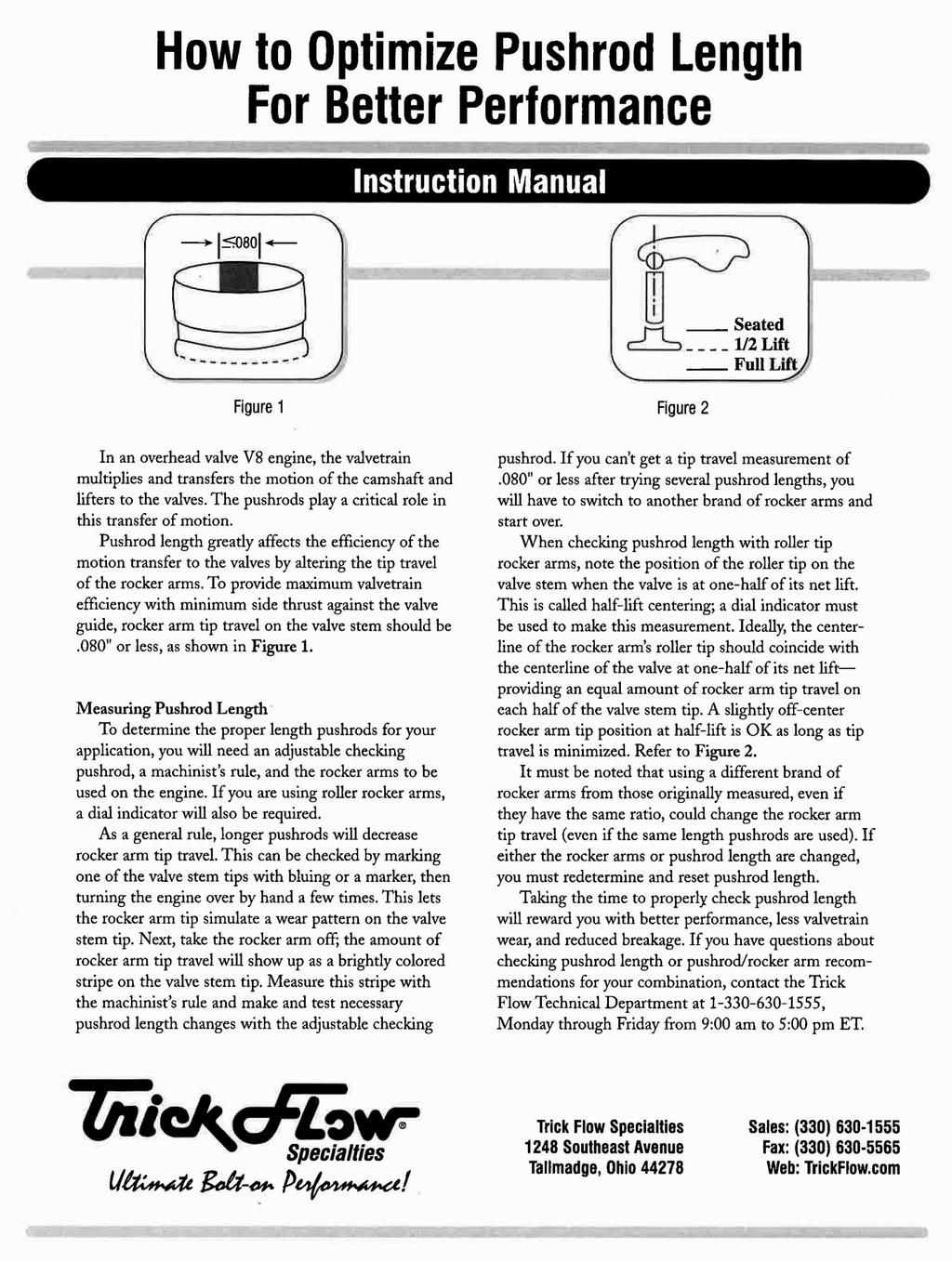
2 Installation Instructions 1) Cylinder Head Removal Consult your shop manual for the proper cylinder head removal procedure for your vehicle. Taking notes, pictures, and even making a video of the disassembly will help you greatly when reinstalling brackets and routing vacuum lines. NOTE: Be sure cylinder #1 is at TDC on the compression stroke. 2) Prepping the Block With the old cylinder heads removed, inspect the cylinder bores for scratches, ridges, and cracks. If everything appears to be OK, put some paper towels in the cylinders to catch loose debris as the old head gaskets are scraped off the engine block s deck surface. Remove all traces of the gaskets and any oil or grease that may be present by wiping the surface with brake cleaner. Check the deck surfaces for flatness by laying a straightedge across the deck lengthwise and sticking a.004" feeler gauge under it. If the feeler gauge fits anywhere under the straightedge, the block will need to be decked or head gasket failure will result. Once the block decks have been cleaned and checked, use a 7/16-14 tap to chase the threads in the head bolt holes. This will clean out old sealer and debris, which is extremely important for preventing leaks and torquing the heads down evenly on the block. After cleaning the head bolt hole threads, carefully remove the paper towels from the cylinders and discard. Using new paper towels, clean the cylinders and coat the cylinder walls with a thin film of engine oil to protect them from corrosion. 3) Checking Header Clearance Place one of the new cylinder heads on a suitable work stand and install the recommended spark plugs (refer to the Recommended Components chart in the Technical specifications sheet for specific part numbers). Bolt the headers to the cylinder head and check for any interference. Repeat this procedure with the other cylinder head. Trick Flow recommends using spark plug wires with 90 degree spark plug boots on header equipped small block Chevy engines. Now is the time to make sure the vehicle s temperature sending unit will work with the ½ -14 NPT threaded hole in the cylinder heads. If the vehicle s sender doesn t fit, locate a suitable replacement or use an adapter bushing to make the sending unit work (refer to the Recommended Components chart on the Technical Specifications sheet for specific part numbers). 4) Checking Piston-to-Valve Clearance and Valvetrain Geometry If you choose to use the stock camshaft in your engine, and it has not been moved from its factory position, you do not have to check piston-to-valve clearance. If you have an aftermarket camshaft or are reinstalling a camshaft (especially with a multi-keyway timing set), you must follow this procedure to assure safe operating clearances between your pistons and valves: A) Rotate the crankshaft until the engine is on the compression stroke of the #1 cylinder. Place a solid mock up lifter in the lifter bore of the valve that you will be measuring. Be sure that the mock up lifter is the same height as the lifters that will be installed in the engine later. B) Place a few 1/4 thick strips of modeling clay across the upper half of the piston. Put a light coat of oil on top of the modeling clay and the valves in the cylinder head to keep the clay and valve from sticking. Place the head gasket you will be using on the block and bolt the head on with five or six head bolts. C) Install the rocker arm studs, guideplate, and the rocker arm for the valve you are checking (intake or exhaust). Next, set your adjustable pushrod tool to the proper length for your combination and tighten the rocker to zero lash, rotate the crankshaft at least twice, remove the cylinder head. D) This is also a good time to verify proper pushrod length and valvetrain geometry. The procedure can be found in the bulletin titled How to Optimize Pushrod Length for Better Performance. E) Gently cut the clay into slices and look for the thinnest section of the valve impression. The impression is a 3D representation of the clearance between the piston and valve. Carefully measure the thickness of the clay with a machinist s scale or calipers. The intake valve side of the clay should have.080" or more of clearance, and the exhaust should have.100" or more of clearance. F) When you have completed these procedures, rotate the crankshaft until the #1 piston is at TDC on the compression stroke. NOTE: Reference the maximum recommended valve lift for the valve springs in the Technical Specifications sheet before purchasing an aftermarket camshaft. 5) Installing the New Cylinder Heads With the block deck surfaces and cylinders clean and all checks completed, position the head gaskets on the block per the manufacturer s markings. Don t be alarmed if some of the holes in the block are restricted by a smaller hole in the gasket. This is done intentionally to regulate coolant flow. Position each cylinder head evenly on the block s dowel pins so that each head lies flat against the gasket. Next, place hardened head bolt washers over each bolt hole. Head bolt washers are required to prevent galling of the aluminum and to get accurate torque readings. Once they are in place, place a small amount of ARP moly lube on the top of all washers. Place thread sealer on the head bolts, and torque the head studs in the three stages shown, following the sequence shown in Figure 1 on the following page.


3 7) Reassembling the Rest of the Engine Install as many items as you can without putting the valve covers on. This will allow you to prelube the valvetrain, which is explained in the Prelubing the Valvetrain section. Stage One: 22 ft.-lbs. Stage Two: Tighten the long and medium bolts as additional 80 degrees using a torque angle meter. Stage Three: Tighten the short length bolts an additional 67 degrees using a torque angle meter. Intake Manifold Tips Apply ¼ bead of Permatex Ultra Black RTV sealer to the intake manifold end rail surfaces. Do not use a gasket on the end rails, only the RTV sealer. Outline the water openings at the ends of the head with Ultra Black to help prevent water leaks. Apply a small amount of motor oil to the intake bolts and torque to factory specifications in the sequence shown below. A cold re-torque after the initial break in period is not required to maintain head gasket integrity and combustion seal, but can be done if desired. 6) Installing and Adjusting the Valvetrain Place the proper length, hardened pushrods into the pushrod holes. Use Permatex 3H Aviation Forma-Gasket to coat the base threads of the rocker studs, and then put the guideplates on. Do not tighten the guideplates down completely and leave the connecting bolt loose. If the rocker studs break into the intake ports, use Teflon tape on the threads. Figure 2 Exhaust Manifold/Header Tips Lay your straightedge across the mating flange of the exhaust manifolds/headers to make sure they are flat. Put a small amount of motor oil on the exhaust bolts and tighten them down from the center out to the ends. This will permit the flange to be tightened evenly. After you run the engine a few times, retighten the exhaust bolts. If the bolts loosen up, the leaking exhaust gas will ruin the gasket. NOTE: What may sound like a lifter tick is often an exhaust gas leak. Rule out exhaust leaks before tearing the intake off to replace the lifters. NOTE: Self-aligning rocker arms do not require guideplates. Instead, a rocker arm shim kit will be required for your GenX cylinder heads in place of guideplates to maintain proper rocker arm stud height. Place the rocker arms on the studs and verify that they are centered side to side. See Figure 2. Once the rocker arms are centered on the valves, gently remove the rocker arm and torque the rocker arm studs to 55 ft.-lbs. Place the rocker arm back on the stud to make sure that they didn t move during tightening. Now tighten the connecting bolt on the guide plate. Adjust the valvetrain according to the camshaft manufacturer s recommendations. If you are using a hydraulic camshaft and no specifications are available, turn the rocker arm adjusting nuts ½ to ¾ of a turn past zero lash. For mechanical camshafts, you must use the correct lash specification determined by the camshaft manufacturer. Use the following adjustment order for all types of camshafts. This is the easiest method to use since it requires only one turn of the crankshaft. A) With the #1 piston at TDC on the exhaust stroke, adjust the exhaust rockers of cylinders #2, #5, #6 and #7, then the intake rockers of cylinders #3, #4, #6 and #8. B) Turn the crankshaft 360 degrees (One full turn) until the #1 piston is at TDC on the compression stroke. Adjust the exhaust rockers of cylinders #1, #3, #4, and #8, then the intake rockers of cylinders #1, #2, #5 and #7. C) Leave the #1 piston at TDC on the compression stroke for the rest of the assembly. 8) Pre-lubing the Valvetrain The valvetrain is now ready to be pre-lubed. Slowly pour a half quart of motor oil (per head) over the rocker arms, valve springs, and valve stems. Use an oil squirt can to get inside the valve spring and lube the valve stem and seal area. Reinstall the valve covers as soon as possible to keep contaminants out of the engine. The valve cover rails on the GenX cylinder heads have been raised approximately.300 to provide clearance for roller rocker arm polylocks. Adjustments to accessories that mount on or cross over the valve covers may be necessary. If you are installing centerbolt-type valve covers with standard type roller rocker arms, you will have to reduce the width of the oil control baffles by squeezing them in the center until they clear. After the valve covers are installed, reinstall the rest of the top end and accessories. DO NOT START THE ENGINE IF THE TOP HALF OF THE ENGINE HAS NOT BEEN PRELUBED! 8) Break-In and Tuning To ensure long life and trouble-free use, allow 2-4 hours of normal driving time before running the engine hard; this will break-in the valvetrain properly. If you installed a new camshaft, change the oil after 30 minutes of run time. This will help remove particles that are shorn off during the break-in process.

4 Technical Specifications Head Material: A-356-T61 Aluminum Comb. Chamber volume: M54: 54cc CNC profiled 10: 62cc As-Cast Intake port volume: M54: 54cc Fast As Cast 10: 195cc Fast As Cast Intake port dimensions: M54: x : x Intake port location: Stock; Exhaust: Stock Intake valve diameter: (TFS ) Valve angles: M54: 21, 10: 23 Intake valve seat: M54: Ductile Iron (TFS ) 10: Tungsten alloy (TFS ) Intake valve stem diameter: 11/32 Exhaust port volume: M54: 67cc Fast As Cast 10: 75cc Fast As Cast Exhaust port dimensions: x D-Shape Exhaust valve diameter: (TFS ) Exhaust valve seat: M54: Ductile iron (TFS ) 10: Tungsten alloy (TFS ) Exhaust valve stem diameter: 11/32 Valve guide material: Bronze Alloy (TFS ) Valve seal: Viton fluoroelastomer (TFS ) Valve seat angles: 45 x multi-angle Valve spring pockets: M54: 1.615" 10: 1.615, (Center two) Valve spring cups: (TFS ) Valve spring retainers: M54: Chromoly 7x O.D. (TFS ) 10: Chromoly 7x O.D. (TFS ) Valve stem locks: 7 steel (TFS ) Valve springs: M54: (TFS ) 1.300" O.D. dual spring with damper " installed height " open 448 lbs. per inch rate.600" maximum lift 10: (TFS ) 1.460" O.D. dual spring with damper " installed height open 420 lbs. per inch rate.600" maximum lift Guide plates: M54: 5/16 (TFS ) 10: 5/16 (TFS ) Push rod length: Longer than stock required, Rocker studs: ARP 3/8 (TFS ) Minimum bore diameter: Weight each bare: 22 lbs. each CARB E.O. number: D Miscellaneous Info: Contains both LT1 and LT4 intake gasket alignment holes Recommended Components Head gasket: Intake gasket: Exhaust gasket: Fel Pro 1470 TFS , bore MLS Fel Pro 1074, bore GM Performance , bore Mr. Gasket 5716, bore LT1: Fel Pro 1284, Steel core laminate LT4: GM Performance Head bolts/studs: ARP , (6pt. bolts) ARP (12pt. studs) Rocker arms: Pistons: TFS (1.5 Ratio; 3/8 stud) Trick Flow brand available Engine gasket kit: TFS Head alignment dowels: TFS A.I.R. passage threaded inserts: TFS Spark plugs: Autolite 3924 Champion RC9YC NGK 7373 Trick Flow Specialties, Trick Flow, TFS and GenX are trademarks of Trick Flow Specialties. No license to use or reproduce any of these trademarks or other trademarks is given or implied. All other brands and product names are the trademarks of their respective owners. Trick Flow GenX heads for small block Chevrolet are not a product of Chevrolet Motor Division, General Motors, nor are they endorsed by Chevrolet. Trick Flow Specialties is not affiliated with Chevrolet in any manner whatsoever. Trick Flow Specialties 285 West Avenue Tallmadge, Ohio Sales: (330) , Fax: (330) Trickflow.com Viton is a registered trademark of DuPont Performance Elastomers. Replacement Cylinder Heads TFS-3041B010 TFS-3041B008-M54 Bare, 195cc, 23 degree, Forced induction engines. Bare, 185cc, 21 degree, Fast As Cast
5

6 Ultimate Bolt-On Performance Lifetime Warranty Trick Flow Specialties cylinder head castings are backed by a lifetime warranty. If a cylinder head casting fails to provide the original purchaser with complete satisfaction, Trick Flow Specialties will repair or replace it free of charge guaranteed! Moreover, the valves, valve guides, valve seats, valve job, valve springs, valve spring retainers, valve locks, rocker arm studs, guideplates, and valve stem seals included on assembled Trick Flow Specialties cylinder heads are warranted to the original purchaser to be free from defects in materials and workmanship for a period of two years from the date of purchase. All other Trick Flow Specialties products are warranted to be free from defects in materials and workmanship for a period of 90 days. There are no mileage limitations. Extent of Warranty Customers who believe they have a defective product should return it to the dealer from which they purchased or ship it freight prepaid to Trick Flow Specialties along with proof of purchase and a complete description of the problem. If a thorough inspection indicates defects in materials or workmanship, our sole obligation is to repair or replace the product. This warranty is only if the product is properly installed, subjected to normal use and service, did not fail due to owner negligence or misuse, and has not been altered or modified. Trick Flow Specialties warranties do not cover any installation or removal costs. Trick Flow Specialties is not liable for consequential damages for breach of contract of any warranty in excess of the purchase price of the product sold. PROPOSITION 65 WARNING This product may contain one or more substances or chemicals known to the state of California to cause cancer, birth defects or other reproductive harm. TRICK FLOW SPECIALTIES 285 WEST AVE. TALLMADGE, OHIO (330)
GenX Street/Strip Cylinder Heads for the GM LT1
 GenX Street/Strip Cylinder Heads for the GM LT1 Thank you for purchasing Trick Flow GenX Street/Strip aluminum cylinder heads for the GM LT1. Please follow the steps outlined in this instruction manual
Twisted Wedge 11R Aluminum Cylinder Heads
 Twisted Wedge 11R Aluminum Cylinder Heads for the Small Block Ford Thank you for purchasing Trick Flow Twisted Wedge 11R aluminum cylinder heads designed for the Small Block Ford. Please follow the steps
Summit 170cc Cylinder Heads
 Summit 170cc Cylinder Heads for the Small Block Chevrolet Thank you for purchasing a set of the Summit 170cc Small Block Chevrolet aluminum cylinder heads. Please follow the steps outlined in this instruction
Twisted Wedge 170 Aluminum Cylinder Heads for the Small Block Ford
 Twisted Wedge 170 Aluminum Cylinder Heads for the Small Block Ford Specialties Thank you for purchasing Trick Flow Twisted Wedge 170 aluminum cylinder heads designed for the Small Block Ford. Please follow
llnl!!i MADE IL.l ln THE USA Super and 195 Cylinder Heads for the Small Block Chevrolet Recommended Tools Project Overview
 llnl!!i MAE IL.l ln THE USA Super 23 175 and 195 Cylinder Heads for the Small Block Chevrolet Thank you for purchasing Trick Flow Super 23 175 and 195 Small Block Chevrolet aluminum cylinder heads. Please
R-Series Cylinder Heads for Big Block Chevy
 Overview Material TFS-41400004 A356-T6 Combustion Chamber Intake Port Exhaust Port Sizes 122cc 340cc 137cc 2.25 in. Intake, Springs 1.530 in. Dual Springs for Mechanical Flat Tappet and Hydraulic Locks
PERFORMER AND PERFORMER RPM CYLINDER HEADS For Small-Block Chevrolet V8 Engines INSTALLATION INSTRUCTIONS
 PERFORMER AND PERFORMER RPM CYLINDER HEADS For Small-Block Chevrolet V8 Engines INSTALLATION INSTRUCTIONS 60619 60639 60659 60697 60715 60719 60735 60739 60759 60849 Catalog #s 60859 60869 60879 60887
PERFORMER AND PERFORMER RPM CYLINDER HEADS For Small-Block Chevrolet V8 Engines INSTALLATION INSTRUCTIONS CATALOG #S
 PERFORMER AND PERFORMER RPM CYLINDER HEADS For Small-Block Chevrolet V8 Engines INSTALLATION INSTRUCTIONS CATALOG #S 60619 60639 60659 60697 60715 60719 60735 60739 60759 60849 60859 60869 60879 60889
Hi-Tech & Pro Magnum Roller Rocker Arms
 Hi-Tech & Pro Magnum Roller Rocker Arms Thank you for choosing COMP Cams products; we are proud to be your manufacturer of choice. Please read this complete instruction sheet carefully (including the application
WEIAND STREET WARRIOR INTAKE MANIFOLD P/N s 8125, 8125P, 8126, & 8126P SMALL BLOCK CHEVROLET
 APPLICATIONS: WEIAND STREET WARRIOR INTAKE MANIFOLD P/N s 8125, 8125P, 8126, & 8126P 262-400 SMALL BLOCK CHEVROLET INSTALLATION INSTRUCTIONS The P/N 8125 & 8126 WEIAND STREET WARRIOR series intake manifolds
INSTALLATION INSTRUCTIONS
 PERFORMER RPM CAMSHAFT / LIFTERS / LUBE KIT For 343-401 c.i.d. AMC V8 Engines CATALOG # 7132 INSTALLATION INSTRUCTIONS PLEASE study these instructions carefully before beginning this installation. Most
WEIAND INTAKE MANIFOLD P/N 7550 SMALL BLOCK CHEVROLET 3x2 BBL
 WEIAND INTAKE MANIFOLD P/N 7550 SMALL BLOCK CHEVROLET 3x2 BBL INTAKE MANIFOLD INSTALLATION INSTRUCTIONS 199R10703 APPLICATIONS: The P/N 7550 WEIAND intake manifold is designed for Holley 3x2 BBL, model
WEIAND X-CELerator Intake Manifold P/N 7516
 WEIAND X-CELerator Intake Manifold P/N 7516 351C FORD, 2V CYLINDER HEADS INSTALLATION INSTRUCTIONS APPLICATIONS: The P/N 7516 X-CELerator intake manifold is designed for square-bore carburetor applications
Precision Degree Wheel Kit
 555-81621 Precision Degree Wheel Kit Instruction Booklet Instructions for 81621 Camshaft Degree Kit Thank you for purchasing the Jegs Camshaft Degree Kit. Please follow these detailed instructions to properly
 Page 1 of 7 1965 Ford Mustang 4.7L Eng VIN A Base Service Manual: 221", 260", 289" V8 ENGINES Print Date: ENGINE NOTES 1962-65 COOLANT LOSS OR WATER PUMP & FRONT COVER CORROSION CORRECTION: May be caused
165cc SBF Outlaw Street Head The Small Port, High Velocity, Emission Legal Torque Monster
 165cc SBF Outlaw Street Head The Small Port, High Velocity, Emission Legal Torque Monster Head Torque---------------------------------------------65-70 Ft. Lbs. with 7/16 stud Pedestal Torque--------------------------------------------------25-30
Model 340 Tune-Up Kit Instructions
 Model 340 Tune-Up Kit Instructions Jacobs P/N 019654 tune-up kit instructions Tune-up Kit Contents Illus. No. Jacobs P/N Part Name Quantity Per Kit 4 020229 Upper Seal Ring 3 5 001082 Center Seal Ring
Installation Instructions
 CHEVROLET ENGINE SYSTEM, NON-EMISSION 1967-1987 SMALL BLOCK CHEVROLET Part Number 300-502 CHEVROLET ENGINE SYSTEM, NON-EMISSION 1962-1987 CHEVROLET 302, 327, 350 C.I.D. ENGINES Part Number 300-503-1 Installation
Roller Camshaft Installation
 Installation Instructions Roller Camshaft Installation For more information, see www.cranecams.com READ CAREFULLY AND COMPLETELY BEFORE INSTALLATION Prior to installation, immerse lifters in a premium
AEROMOTIVE Part # /2 4.6L SOHC Ford Fuel Rail Kit INSTALLATION INSTRUCTIONS
 AEROMOTIVE Part # 14125 96-98 1/2 4.6L SOHC Ford Fuel Rail Kit INSTALLATION INSTRUCTIONS CAUTION: Installation of this product requires detailed knowledge of automotive systems and repair procedures. We
AEROMOTIVE Part # / L SOHC Ford Fuel Rail Kit INSTALLATION INSTRUCTIONS
 AEROMOTIVE Part # 14119 98 1/2-04 4.6L SOHC Ford Fuel Rail Kit INSTALLATION INSTRUCTIONS CAUTION: Installation of this product requires detailed knowledge of automotive systems and repair procedures. We
Superior Design. Advanced Manufacturing. Proven Performance.
 Superior Design. Advanced Manufacturing. Proven Performance. Trick Flow Specialties reputation was earned by creating, engineering, and manufacturing budget-friendly cylinder heads that deliver phenomenal
Iron GEN III - Technical Notes
 DART Iron GEN III - Technical Notes Deck Height... 9.240" Bore... 4.000 & 4.125 Main Bearing Size... LS-1 (2.558" 2.559") Weight... 227lbs Largest Recommended Bore..... 4.185" Largest Recommended Crank
AEROMOTIVE Part # Ford 5.4L GT500 Shelby Mustang Fuel Rail Kit INSTALLATION INSTRUCTIONS
 AEROMOTIVE Part # 14145 07 Ford 5.4L GT500 Shelby Mustang Fuel Rail Kit INSTALLATION INSTRUCTIONS CAUTION: Installation of this product requires detailed knowledge of automotive systems and repair procedures.
Holley GM BBC Single-Plane EFI Intake Manifold Kits
 Holley GM BBC Single-Plane EFI Intake Manifold Kits 300-561 Oval Port, 4150 Flange 300-562 Oval Port, 4500 Flange 300-563 Rectangular Port, 4150 Flange 300-564 Rectangular Port, 4500 Flange INSTALLATION
NO PART OF THIS DOCUMENT MAY BE REPRODUCED WITHOUT PRIOR AGREEMENT AND WRITTEN PERMISSION OF FORD RACING PERFORMANCE PARTS. STOP! READ THIS!
 STOP! READ THIS! THIS ENGINE REQUIRES RACING OIL THAT CONTAINS 1200 PPM (parts per million) ZDDP (zinc-dialkyl-dithio-phosphate). THIS ENGINE IS SHIPPED WITHOUT OIL! Page 1 of 6 Please contact the Tech
Skirted GEN III - Technical Notes
 DART Skirted GEN III - Technical Notes Deck Height... 9.240-9.450 STD or Raised cam, 9.750 9.950 Raised cam only Bore... 4.000 & 4.125 Main Bearing Size... LS-1 (2.558" 2.559") Weight... 115lbs 4.125 and
AEROMOTIVE Part # Ford 5.0 Liter INSTALLATION INSTRUCTIONS
 AEROMOTIVE Part # 14101 86-98 Ford 5.0 Liter INSTALLATION INSTRUCTIONS CAUTION: Installation of this product requires detailed knowledge of automotive systems and repair procedures. We recommend that this
AEROMOTIVE Part # Subaru Fuel Rails for Top Feed Injectors WRX & STI INSTALLATION INSTRUCTIONS
 AEROMOTIVE Part # 14135 Subaru Fuel Rails for Top Feed Injectors 02-14 WRX & 07-14 STI INSTALLATION INSTRUCTIONS CAUTION: Installation of this product requires detailed knowledge of automotive systems
NO PART OF THIS DOCUMENT MAY BE REPRODUCED WITHOUT PRIOR AGREEMENT AND WRITTEN PERMISSION OF FORD RACING PERFORMANCE PARTS.
 Please visit www.fordracingparts.com for the most current instruction information!!! PLEASE READ ALL OF THE FOLLOWING INSTRUCTIONS CAREFULLY PRIOR TO INSTALLATION. AT ANY TIME YOU DO NOT UNDERSTAND THE
Block & Side Cover 4-5. Crank, Piston & Rod 6-7. Cylinder Head 8-9. Cam & Valve train Carburetor / Manifold Flywheel & Ignition 14-15
 Table of Contents 2-1-2005 Title Page Block & Side Cover 4-5 Crank, Piston & Rod 6-7 Cylinder Head 8-9 Cam & Valve train 10-11 Carburetor / Manifold 12-13 Flywheel & Ignition 14-15 Assembly & 6 Packs 16
THANK YOU FOR PURCHASING OUR ROCKERS
 THANK YOU FOR PURCHASING OUR ROCKERS We have designed and engineered these Real Chrysler rockers specifically for MOPAR wedge engines (not something modified to be close enough to work on a MOPAR). The
GENERAL INSTRUCTIONS. PERFORMER-PLUS CAMSHAFT / LIFTERS / LUBE KIT MODEL: c.i.d. Chevrolet V8 Engines CATALOG #2117
 Page 1 PERFORMER-PLUS CAMSHAFT / LIFTERS / LUBE KIT MODEL: 283-400 c.i.d. Chevrolet V8 Engines GENERAL INSTRUCTIONS PLEASE study these instructions carefully before beginning this installation. Most installations
Performer-Plus 5.0L Hydraulic Roller Lifter Camshaft only CATALOG #3722 MODEL: 5.0 Litre Ford V8, 1985 & later INSTRUCTIONS
 Performer-Plus 5.0L Hydraulic Roller Lifter Camshaft only CATALOG #3722 MODEL: 5.0 Litre Ford V8, 1985 & later INSTRUCTIONS PLEASE study these instructions carefully before installing your new camshaft.
For JBA Headers 641/2 to /302/5.0L EFI Ford Mustang & Mercury Cougar
 Corporate Office: PerTronix Inc. 440 E. Arrow Highway, San Dimas, California 91773 * Phone 909.599.5955 FAX 909.599.6424 Installation Instructions and Warranty Information For JBA Headers 641/2 to 73 289/302/5.0L
M-6007-Z351SR Sealed Crate Engine INSTRUCTION SHEET
 Please visit www.fordracingparts.com for the most current instruction information!!! PLEASE READ ALL OF THE FOLLOWING INSTRUCTIONS CAREFULLY PRIOR TO INSTALLATION. AT ANY TIME YOU DO NOT UNDERSTAND THE
Read all instructions before beginning machining or assembly.
 A4 blocks now come with steel billet main caps only (all 5 are cross bolted. Aluminum replacement caps can be special ordered directly from Pro Gram Engineering phone (330) 745-1004. Head Studs: Head stud
AEROMOTIVE Part # L Ford F L Ford Expedition L Ford F-250 Super Duty INSTALLATION INSTRUCTIONS
 AEROMOTIVE Part # 14118 97-03 5.4L Ford F-150 97-02 5.4L Ford Expedition 98-03 5.4L Ford F-250 Super Duty INSTALLATION INSTRUCTIONS CAUTION: Installation of this product requires detailed knowledge of
Thank You. for purchasing an Edelbrock Nitrous Oxide Injection System. Please take the time to read and understand the following.
 Thank You. for purchasing an Edelbrock Nitrous Oxide Injection System. Nitrous Oxide injection is one of the most exciting performance enhancements for the dollar invested on the market today. With the
1995 Aerostar/Ranger/Explorer
 Page 1 of 13 Section 03-01C: Engine, 4.0L V-6 DISASSEMBLY AND ASSEMBLY 1995 Aerostar/Ranger/Explorer Workshop Manual Engine Disassembly 1. NOTE: Before starting disassembly, remove all wiring harnesses,
PERFORMER-PLUS CAMSHAFT / LIFTERS / LUBE KIT MODEL: 351-M/400 c.i.d. Ford V8 CATALOG #2172 INSTALLATION INSTRUCTIONS
 PERFORMER-PLUS CAMSHAFT / LIFTERS / LUBE KIT MODEL: 351-M/400 c.i.d. Ford V8 INSTALLATION INSTRUCTIONS Please study these instructions carefully before installing your new camshaft. If you have any questions
AEROMOTIVE Part # Subaru STI Fuel Rail Kit INSTALLATION INSTRUCTIONS
 AEROMOTIVE Part # 14137 04-06 Subaru STI Fuel Rail Kit INSTALLATION INSTRUCTIONS CAUTION: Installation of this product requires detailed knowledge of automotive systems and repair procedures. We recommend
CYLINDER HEAD OVERHAUL
 ENGINE OVERHAUL PROCEDURES - GENERAL INFORMATION -2011 Mercedes-... Page 1 of 20 CYLINDER HEAD OVERHAUL * PLEASE READ THIS FIRST * Examples used in this article are general in nature and do not necessarily
SPECIFICATIONS TEST AND ADJUSTMENT SPECIFICATIONS SPECIFICATIONS ENGINE FD620D, K SERIES
 TEST AND ADJUSTMENT Engine Oil Pressure Sensor Activates............................... 98 kpa (14.2 psi) Oil Pressure While Cranking (Minimum).......................... 28 kpa (4 psi) Oil Pressure.....................................
Remove Air Cleaner Cover and. Filter
 Remove Air Cleaner Cover and Inspect paper filter for tears Foam pre-cleaner is washable if equipped Replace if necessary Filter Remove Trim Panel Pull throttle lever knob off Remove 3, 8mm screws Remove
PERFORMER-PLUS CAMSHAFT / LIFTERS / LUBE KIT CATALOG # 2103 MODEL: 400 c.i.d. Chevrolet V8 engines GENERAL INSTRUCTIONS
 PERFORMER-PLUS CAMSHAFT / LIFTERS / LUBE KIT CATALOG # 2103 MODEL: 400 c.i.d. Chevrolet V8 engines GENERAL INSTRUCTIONS Please study these instructions carefully before you remove your stock camshaft.
Installation Instructions And Warranty Information
 Corporate Office: PerTronix Inc. 440 E. Arrow Highway, San Dimas, California 91773 * Phone 909.599.5955 FAX 909.599.6424 Installation Instructions And Warranty Information 1964 1/2 to 73 Ford Mustang/Mercury
FREE $15 Gift Card for every $100 spent on Ship To Home orders. Find Out How
 1 of 29 10/12/2011 5:05 PM FREE $15 Gift Card for every $100 spent on Ship To Home orders. Find Out How Ford Ranger/Explorer/Mountaineer 1991-1999 Intake Manifold REMOVAL & INSTALLATION Print The engines
FORD V8 ENGINES 209. the treated area, the block is cracked and should be replaced.
 FORD V8 ENGINES 209 Cylinder block Core plug Strike here with hammer Drift 8 the treated area, the block is cracked and should be replaced. 3. Check flatness of the cylinder block deck. Place an accurate
AEROMOTIVE Part # L 4V Fuel Rails INSTALLATION INSTRUCTIONS
 AEROMOTIVE Part # 14130 5.0L 4V Fuel Rails INSTALLATION INSTRUCTIONS CAUTION: Installation of this product requires detailed knowledge of automotive systems and repair procedures. We recommend that this
AEROMOTIVE Volkswagen 1.8T Fuel Rail Part # INSTALLATION INSTRUCTIONS
 AEROMOTIVE Volkswagen 1.8T Fuel Rail Part # 14163 INSTALLATION INSTRUCTIONS CAUTION: Installation of this product requires detailed knowledge of automotive systems and repair procedures. We recommend that
SPECIFICATIONS TEST AND ADJUSTMENT SPECIFICATIONS SPECIFICATIONS ENGINE FD620D, K SERIES
 ENGINE FD620D, K SERIES SPECIFICATIONS SPECIFICATIONS TEST AND ADJUSTMENT SPECIFICATIONS Engine Oil Pressure Sensor Activates............................... 98 kpa (14.2 psi) Oil Pressure While Cranking
For JBA Headers /302 Mustang
 Corporate Office: PerTronix Inc. 440 E. Arrow Highway, San Dimas, California 91773 * Phone 909.599.5955 FAX 909.599.6424 Installation Instructions and Warranty Information For JBA Headers 1965-1973 289/302
Engine. Special Tool(s) Compressor, Piston Ring 303-D032 (D81L-6002-C) or equivalent. Compressor, Valve Spring (T93P-6565-AR)
 Compressor, Piston Ring 303-D032 (D81L-6002-C) or equivalent. Compressor, Valve Spring (T93P-6565-AR)") SECTION 303-01C: Engine 5.4L (4V) 2009 Mustang Workshop Manual ASSEMBLY Procedure revision date: 12/12/2008 Engine Special Tool(s) Compressor, Piston Ring 303-D032 (D81L-6002-C) or equivalent Compressor,
SECTION 303-01C: Engine 5.4L (4V) 2009 Mustang Workshop Manual ASSEMBLY Procedure revision date: 12/12/2008 Engine Special Tool(s) Compressor, Piston Ring 303-D032 (D81L-6002-C) or equivalent Compressor,
PERFORMER RPM Camshaft/Lifters/Lube Kit CATALOG #7122 MODEL: c.i.d. Ford V8 (not for Boss 302 or 1985 & later roller lifter engines)
") PERFORMER RPM Camshaft/Lifters/Lube Kit MODEL: 289-302 c.i.d. Ford V8 (not for Boss 302 or 1985 & later roller lifter engines) PLEASE study these instructions carefully before installing your new camshaft.
PERFORMER RPM Camshaft/Lifters/Lube Kit MODEL: 289-302 c.i.d. Ford V8 (not for Boss 302 or 1985 & later roller lifter engines) PLEASE study these instructions carefully before installing your new camshaft.
INSTALLATION INSTRUCTIONS
 INSTALLATION INSTRUCTIONS Thank you for purchasing a LOMAX TM Hard Tri-Fold or Professional Series Cover. Agri-Cover, Inc. proudly manufactured this cover using superior quality materials and workmanship.
Zoom and Print Options
 Vehicle» Engine, Cooling and Exhaust» Engine» Cylinder Head Assembly» Service and Repair» Procedures» Removal Cylinder Heads http://repair.alldata.com/alldata/article/display.action?componentid=65&itypeid=376&nonstandardid=682956&vehicleid=45317&windowname=maina
AEROMOTIVE Part # INSTALLATION INSTRUCTIONS
 AEROMOTIVE Part # 14102 INSTALLATION INSTRUCTIONS CAUTION: Installation of this product requires detailed knowledge of automotive systems and repair procedures. We recommend that this installation be carried
TORKER-PLUS Camshaft/Lifters/Lube Kit Part #5022 MODEL: c.i.d. Ford V8 (not for Boss 302 or 1985 & later roller lifter engines)
") TORKER-PLUS Camshaft/Lifters/Lube Kit MODEL: 289-302 c.i.d. Ford V8 (not for Boss 302 or 1985 & later roller lifter engines) PLEASE study these instructions carefully before installing your new camshaft.
TORKER-PLUS Camshaft/Lifters/Lube Kit MODEL: 289-302 c.i.d. Ford V8 (not for Boss 302 or 1985 & later roller lifter engines) PLEASE study these instructions carefully before installing your new camshaft.
BEFORE BEGINNING INSTALLATION
 EDELBROCK E-FORCE SUPERCHARGER KITS Catalog #1551, 15511, 1552, 15521, 1553, 15531, 1554, 15541, 15611, 15621, 15631, 15641 INSTALLATION INSTRUCTIONS PLEASE study these instructions carefully before beginning
Read all instructions carefully before attempting installation. 1633S-1JS Shown. Rev DSL
 Corporate Office: PerTronix Inc. 440 E. Arrow Highway, San Dimas, California 91773 * Phone 909.599.5955 FAX 909.599.6424 Installation Instructions and Warranty Information 1630S 86-87 Ranger/Bronco II
ONLINE PRODUCT REGISTRATION:
 Atomic AirForce Intake Manifold for LT-1 2014-on Corvette PN 2700, PN 27003 (Black), PN 27004 (Gray) ONLINE PRODUCT REGISTRATION: Register your MSD product online. Registering your product will help if
M-6007-Z363 Crate Engine Specifications and Owner's Manual
 M-6007-Z363 Crate Engine Specifications and Owner's Manual!!! PLEASE READ ALL OF THE FOLLOWING INSTRUCTIONS CAREFULLY PRIOR TO INSTALLATION. INSTALLATION INSTRUCTIONS: These instructions consist of (4)
FORD 351W Small Block Technical Notes
 DART FORD 351W Small Block Technical Notes Deck Height 9.200 & 9.500 Bore 4.00 or 4.125 unfinished Main Bearing Size 302 (2.249 ) & 351C (2.749 ) Weight. 9.200 190 lb / 9.500 195 lb Maximum bore 4.185
TH400 STREETFIGHTER SERIES VALVE BODY MANUAL/AUTO VALVE BODY INSTALLATION INSTRUCTIONS
 1 INSTRUCTIONS TH400 STREETFIGHTER SERIES VALVE BODY 1965-87 MANUAL/AUTO VALVE BODY INSTALLATION INSTRUCTIONS TCI 222400 TCI 222400 ALLOWS AUTOMATIC SHIFT FEATURES IN THE DRIVE POSITION Thank you for choosing
Pro Iron Small Block - Technical Notes
 DART Pro Iron Small Block - Technical Notes Deck Height... 9.025" Bore... 4.00" or 4.125" unfinished Main Bearing Size... 350 (2.45") & 400 (2.65") Weight... 175 lbs Largest Recommended Bore... 4.165"
LSX Intake Manifold. #54001 LSX (78mm Throttle Body) #54003 LSX (90mm Throttle Body)
 #54003 LSX (90mm Throttle Body)") LSX Intake Manifold #54001 LSX (78mm Throttle Body) #54003 LSX (90mm Throttle Body) Thank you for your purchase of the most innovative and powerful Gen III (LS1 and LS6) manifold ever developed. We are
LSX Intake Manifold #54001 LSX (78mm Throttle Body) #54003 LSX (90mm Throttle Body) Thank you for your purchase of the most innovative and powerful Gen III (LS1 and LS6) manifold ever developed. We are
Edelbrock E-Force RPM Carburetor Supercharger C.I.D. Small-Block Chevy
 Edelbrock E-Force RPM Carburetor Supercharger 302-400 C.I.D. Small-Block Chevy 1986 and Earlier Style Heads: 1513, 1514, 15131, 15133, 15141, 15143 E-Tec and Vortec Style Heads: 1515, 1516, 15151, 15153,
(C6) Chevrolet Corvette Crank Scraper and Oil Pan Baffle Kit
 Chevrolet Corvette Crank Scraper and Oil Pan Baffle Kit") 2005-2013 (C6) Chevrolet Corvette Crank Scraper and Oil Pan Baffle Kit Part No. EGM-21X Made in USA Important: Read these instructions in their entirety prior to installation. Rev 160614 Applications 2005-2013
2005-2013 (C6) Chevrolet Corvette Crank Scraper and Oil Pan Baffle Kit Part No. EGM-21X Made in USA Important: Read these instructions in their entirety prior to installation. Rev 160614 Applications 2005-2013
Instructions For Trick Flow Track Heat 4.6L 2V SOHC Ford Intake Manifold System TFS-518B0002, TFS , TFS
 MADE IN U.S.A. Instructions For Trick Flow Track Heat 4.6L 2V SOHC Ford Intake Manifold System TFS-518B0002, TFS-51800002, TFS-51811002 1999-2004 FORD MUSTANG GT INSTALLATION INSTRUCTIONS 1 LIMITED WARRANTY
INSTRUCTIONS AND SERVICE MANUAL WITH PARTS LIST
 CMP SERIES CPM15-15B (25905F300) CPM15-15B-H/D (25905F301) CPM18-15B (25905F303) CPM18-15B-H/D (25905F304) INDUSTRIAL PUMPS INSTRUCTIONS AND SERVICE MANUAL WITH PARTS LIST NOTE! To the installer: Please
460cc Do-It-Yourself Assembly Guide
 2995 Coleman St North Las Vegas, NV 89032 702-530-7753 702-643-7517 FAX VegasCarts.com 460cc Do-It-Yourself Assembly Guide *DIY Engines do not come with a warranty, these kits are intended for experienced
Prerequisites: Shop Manual (recommended) pages 3-9 through 3-13.
 pages 3-9 through 3-13.") Prerequisites: Order your gaskets average about $25.00 bucks X 2 so $50.00 4NK-11193-00-00 Obtain a shim kit (Should have several 265 and 270s) (Some dealers will exchange) Obtain a Valve Bucket Tool YM-33961
Prerequisites: Order your gaskets average about $25.00 bucks X 2 so $50.00 4NK-11193-00-00 Obtain a shim kit (Should have several 265 and 270s) (Some dealers will exchange) Obtain a Valve Bucket Tool YM-33961
Ford Racing Hot Rod Performance Camshafts (05-10 GT)
") Time Necessary: 8 hours Tools Required: Ford Racing Hot Rod Performance Camshafts (05-10 GT) 10mm deep socket 11mm socket 8 mm deep socket 15 mm deep socket 18 mm deep socket Universal Joint socket (articulated
Time Necessary: 8 hours Tools Required: Ford Racing Hot Rod Performance Camshafts (05-10 GT) 10mm deep socket 11mm socket 8 mm deep socket 15 mm deep socket 18 mm deep socket Universal Joint socket (articulated
PERFORMER RPM Camshaft/Lifters/Lube Kit CATALOG #7194 MODEL: c.i.d. Chrysler V8, 1968 & later
 PERFORMER RPM Camshaft/Lifters/Lube Kit MODEL: 413-426-440 c.i.d. Chrysler V8, 1968 & later PLEASE study these instructions carefully before installing your new camshaft. If you have any questions, do
World Formula TECH MANUAL
 World Formula TECH MANUAL Section 1 General Rules 1. Only stock Briggs & Stratton World Formula Model # 124435-8101 will be used in this class except as provided in this Tech manual. All parts will be
AEROMOTIVE Part # GM LS1 Fuel Rails INSTALLATION INSTRUCTIONS
 AEROMOTIVE Part # 14106 GM LS1 Fuel Rails INSTALLATION INSTRUCTIONS CAUTION: Installation of this product requires detailed knowledge of automotive systems and repair procedures. We recommend that this
For more information, see
 Crane Sportsman Shaft-Mount Rocker Arms are designed for serious Sportsman and Professional racers. This system was designed to take advantage of the latest developments in advanced composite materials
Installation Manual. Model T675A Engine Brakes. For Mack 6 Cylinder, 2 valve Head ENDT-673, 675, 676 & E6 Series Engines.
 Engine Brakes Installation Manual Model T675A Engine Brakes For Mack 6 Cylinder, 2 valve Head ENDT-673, 675, 676 & E6 Series Engines TecBrake P.O. Box 27822 Houston, Texas 77227 INSTALLATION MANUAL TECBRAKE
INSTALLATION INSTRUCTIONS
 Equipped with AEM Dryflow Filter No Oil Required! INSTALLATION INSTRUCTIONS PART NUMBER: 24-6105 2002-2006 ACURA RSX - Excludes Type S L4-2.0L C.A.R.B. E.O. # D-670 * NOTE: Legal in California only for
Intake Manifold Removal (Upper)
") Intake Manifold Removal (Upper) Disconnect the vacuum lines from the upper intake manifold. Disconnect the MAP sensor electrical connector. Remove the MAP sensor screws. Remove the MAP sensor. Remove the
Intake Manifold Removal (Upper) Disconnect the vacuum lines from the upper intake manifold. Disconnect the MAP sensor electrical connector. Remove the MAP sensor screws. Remove the MAP sensor. Remove the
HOW TO INSTALL FORD RACING HOT ROD PERFORMANCE CAMSHAFTS MUSTANG GT
 HOW TO INSTALL FORD RACING HOT ROD PERFORMANCE CAMSHAFTS 2005-2010 MUSTANG GT INSTALLATION TIME: 8 HOURS Introduction: This instruction set is intended to be a step by step guide for installing Ford Racing
MSD Pro-Billet Dual Pickup Chevrolet V8 Distributor
 MSD Pro-Billet Dual Pickup Chevrolet V8 Distributor PN 8356 Important: Read these instructions before attempting the installation. Parts Included: 1 - Pro-Billet Distributor 1 - Rotor, PN 8467 1 - Distributor
Kit Part Number:
 Equipped with AEM DRYFLOW Filter No oil required! Kit Part Number: 21-8203 2003-2005 Dodge Ram 5.7L V8 CARB EO # D-392-28 2005 Dodge Powerwagon Hemi CARB EO # D-392-28 Brute Force Intake Systems that are
MSD Pro-Billet Marine Distributor Chevrolet, PN 8560, with Slip Collar, PN 8562, Ford, PN 85806
 MSD Pro-Billet Marine Distributor Chevrolet, PN 8560, with Slip Collar, PN 8562, Ford, PN 85806 Important: Read these instructions before attempting the installation. Parts Included: 1 - Pro-Billet Distributor
DART Aluminum FORD 351 Small Block Technical Notes
 DART Aluminum FORD 351 Small Block Technical Notes Deck Height 9.200 & 9.500 Bore 4.00 or 4.125 unfinished Main Bearing Size 302 (2.249 ) or 351C (2.749 ) Weight. 9.200 91 lb / 9.500 93 lb Maximum bore
Kit Part Number:
 Equipped with AEM DRYFLOW Filter No Oil Required! Kit Part Number: 21-682 2008 Chevrolet Cobalt SS CARB EO - D-392-32 2009, Advanced Engine Management, Inc. AEM is a registered trademark of Advanced Engine
Engine. Special Tool(s) Compressor, Valve Spring (T97P-6565-AH) Compressor Spacer, Valve Spring (T91P-6565-AH)
 Compressor, Valve Spring (T97P-6565-AH) Compressor Spacer, Valve Spring (T91P-6565-AH)") Page 1 of 41 SECTION 303-01A: Engine 5.4L (2V) 2000 F-Super Duty 250-550/Excursion/F-53 Motorhome Chassis Workshop Manual ASSEMBLY Procedure revision date: 04/04/2003 Engine Special Tool(s) Compressor,
Page 1 of 41 SECTION 303-01A: Engine 5.4L (2V) 2000 F-Super Duty 250-550/Excursion/F-53 Motorhome Chassis Workshop Manual ASSEMBLY Procedure revision date: 04/04/2003 Engine Special Tool(s) Compressor,
1.2.5 Installation of Cylinder Head
 SERIES 50 SERVICE MANUAL 1.2.5 Installation of Cylinder Head Perform the following steps for cylinder head installation: 1. Be sure piston domes and the cylinder head and cylinder block firedeck surfaces
1-3/4" or 1-7/8" headers Aftermarket/re-curved distributors
 TORKER-PLUS Camshaft/Lifters/Lube Kit #5062 for 1967 & later 396-454 c.i.d. Chevrolet (not for use in 1965-66 396 & 427 engines requiring grooved rear journal) PLEASE study these instructions carefully
INSTALLATION INSTRUCTIONS
 INSTALLATION INSTRUCTIONS Thank you for purchasing ACCESS Original Roll-Up Cover. Agri-Cover, Inc. proudly manufactured this cover using superior quality materials and workmanship. With proper care, your
WATER PUMP INSTALLATION INSTRUCTIONS WEIAND WATER PUMPS ACTION PLUS & TEAM G APPLICATIONS FOR SMALL BLOCK & BIG BLOCK CHEVROLETS
 WATER PUMP INSTALLATION INSTRUCTIONS WEIAND WATER PUMPS ACTION PLUS & TEAM G APPLICATIONS FOR SMALL BLOCK & BIG BLOCK CHEVROLETS APPLICATIONS: Weiand Action Plus aluminum water pumps are designed for street/performance
TK08 TUNING KIT TECHNICAL MANUAL FOR 16/26/27/28 SERIES SHOCKS Revised 6/25/14 Tech Line: (952) Fax (952)
 Fax (952)") Tech Line: (952) 985-5675 Fax (952) 985-5679 21730 Hanover Ave. Lakeville, MN 55044 www.qa1.net www.facebook.com/qa1motorsports TK08 TUNING KIT TECHNICAL MANUAL CONTENTS UNDER PRESSURE! USE EXTREME CAUTION
Tech Line: (952) 985-5675 Fax (952) 985-5679 21730 Hanover Ave. Lakeville, MN 55044 www.qa1.net www.facebook.com/qa1motorsports TK08 TUNING KIT TECHNICAL MANUAL CONTENTS UNDER PRESSURE! USE EXTREME CAUTION
AEROMOTIVE Part # C5 Corvette Fuel Rail Kit INSTALLATION INSTRUCTIONS
 AEROMOTIVE Part # 14128 99-04 C5 Corvette Fuel Rail Kit INSTALLATION INSTRUCTIONS CAUTION: Installation of this product requires detailed knowledge of automotive systems and repair procedures. We recommend
For For more information, see
 Crane Sportsman Shaft-Mount Rocker Arms are designed for serious Sportsman and Professional racers. This system was designed to take advantage of the latest developments in advanced composite materials
INSTALLATION MANUAL. TORQ Locker TL GM 14 Bolt Installation Instructions. Made in USA By: Page 1 of 8
 INSTALLATION MANUAL TORQ Locker TL-19035 GM 14 Bolt Installation Instructions Made in USA By: Page 1 of 8 Page 2 of 8 INSTALLATION MANUAL TORQ Locker TL-19035 GM 14 Bolt Installation Instructions By: INTRODUCTION
INTEGRATED ENGINE BRAKE. P55003 P67 LoadLeash Kit: 2007½-2013 Dodge Pickup Trucks & Sterling Chassis Cab Trucks w/ Cummins 6.
 INTEGRATED ENGINE BRAKE P55003 P67 LoadLeash Kit: 2007½-2013 Dodge Pickup Trucks & Sterling Chassis Cab Trucks w/ Cummins 6.7L Diesel Engines P55004 P67 LoadLeash Kit: 2014-2015 Dodge Pickup Trucks & Chassis
Installation Manual For ISL98, ISL03, ISL07, ISC07
 Installation Manual For ISL98, ISL03, ISL07, ISC07 Table of Contents Section 1: Introduction... 3 Housing Identification... 3 Engine Identification... 3 Special Tools... 3 Automatic Transmissions... 3
AEROMOTIVE Part # Ford 5.4L Shelby GT500 Mustang INSTALLATION INSTRUCTIONS
 AEROMOTIVE Part # 14144 07 Ford 5.4L Shelby GT500 Mustang INSTALLATION INSTRUCTIONS CAUTION: Installation of this product requires detailed knowledge of automotive systems and repair procedures. We recommend
Disassembly and Assembly
 SENR9973-01 September 2007 Disassembly and Assembly 400C Industrial Engine HB (Engine) HD (Engine) HH (Engine) HL (Engine) HM (Engine) HN (Engine) HP (Engine) HR (Engine) Important Safety Information Most