Twisted Wedge 11R Aluminum Cylinder Heads
|
|
|
- Cornelia Patterson
- 6 years ago
- Views:
Transcription


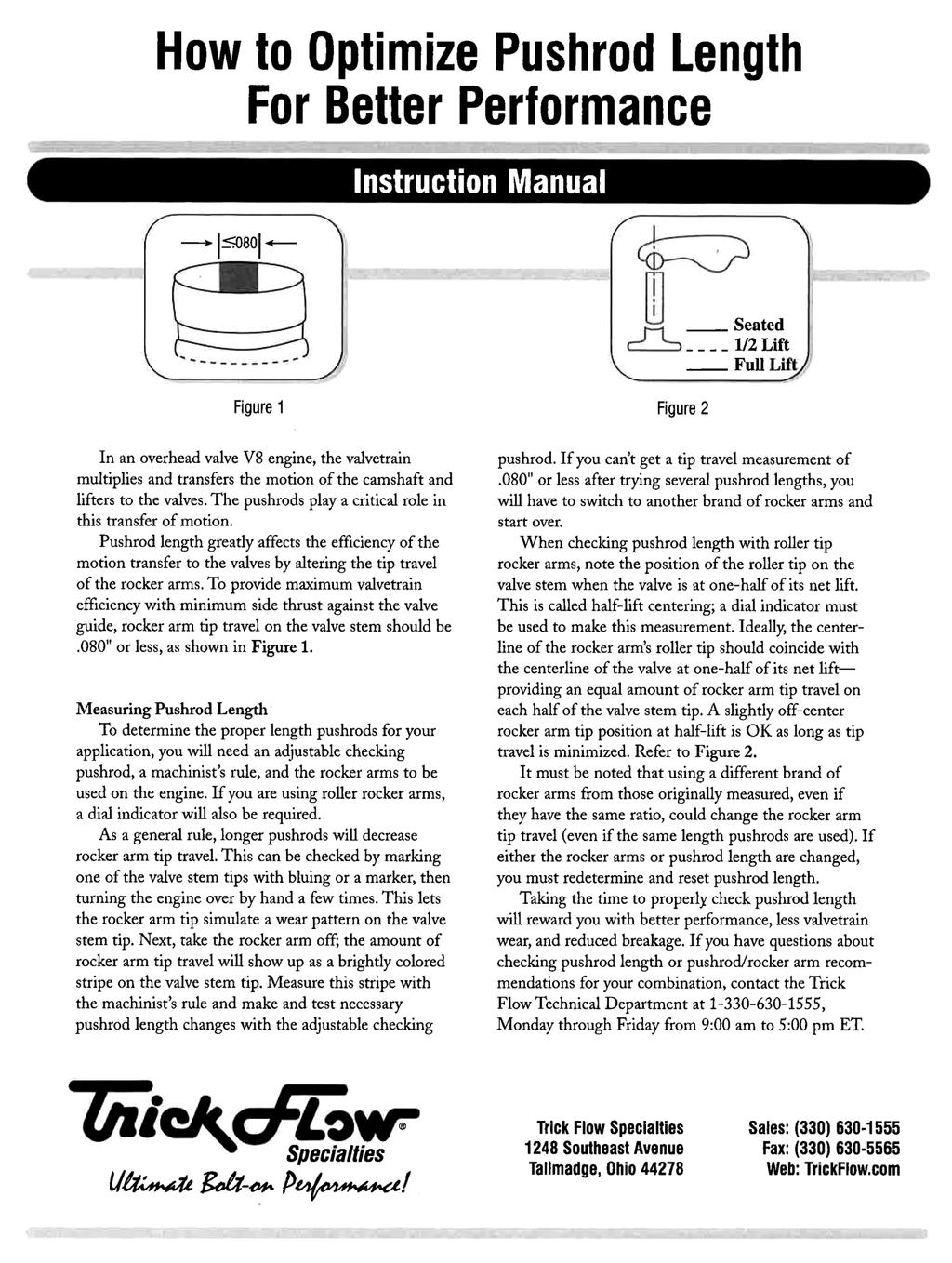
1 Twisted Wedge 11R Aluminum Cylinder Heads for the Small Block Ford Thank you for purchasing Trick Flow Twisted Wedge 11R aluminum cylinder heads designed for the Small Block Ford. Please follow the steps outlined in this instruction manual to ensure that the installation of your new cylinder heads is done correctly and that they perform according to design. Please read all of the enclosed information before beginning any work. If you have any questions regarding installation or the written materials supplied with your new heads, contact the Trick Flow technical department at for assistance, Monday through Friday from 9:00 am to 5:00 pm ET. Project Overview Review all paperwork included in the installation packet Inspect the condition of all components Verify the part numbers and quantities of each product received (see Parts Checklist below) Mail the warranty card to Trick Flow Locate recommended tools Purchase any additional parts needed (See the Additional Parts Required section. Do not purchase pushrods until the proper length has been determined) Remove existing cylinder heads Clean and inspect the engine block Check header fitment Install new cylinder head locating dowels Modify water transfer holes (351 SVO and all pre-1972 blocks) Verify the head bolt size for your application Check piston to valve clearance Check pushrod length Purchase the appropriate length pushrods Install the new cylinder heads Adjust the valvetrain Make tuning adjustments Perform a proper break-in Test drive and enjoy! Parts Checklist You should have received the parts listed here. Please verify the part numbers and quantities of each component received. (1) Assembled cylinder head (1) Instruction packet (4) Guideplates (8) Rocker studs (1) 5/8-11 threaded inserts (Twisted Wedge street heads) If you are missing an item or a part was received in error, please contact Trick Flow at , Monday through Friday from 9:00 am to 5:00 pm ET. Recommended Tools Shop Manual for your vehicle Basic mechanics tool set (SAE/Metric sockets and combination wrenches) ft.-lbs. torque wrench Quick disconnect tools for fuel connections (EFI applications) Timing light, vacuum gauge, and spark plug gap tool 7/16-14 or 1/2-13 tap and handle 3/16 drill bit (not required for all applications) Straightedge Feeler gauge Modeling clay Adjustable pushrod (TFS-9001) Solid mock up lifter Additional Parts Required These components are required to complete the installation of your new cylinder heads. Please refer to the Recommended Components chart on the Technical Specifications sheet for specific part numbers. Head gaskets Intake gaskets Exhaust gaskets Head bolts Head bolt bushings Intake bolts Exhaust bolts Moly lube Spark plugs RTV sealer Pushrods Rocker arms Cylinder head locating dowels Thread locker Thread sealer

2 Installation Instructions 1) Cylinder Head Removal Consult your shop manual for the proper cylinder head removal procedure for your vehicle. Taking notes, pictures, and even making a video of the disassembly will help you greatly when reinstalling brackets and routing vacuum lines. NOTE: Be sure cylinder #1 is at TDC on the compression stroke and mark the distributor s rotor position on the firewall before disassembly. 2) Prepping the Block With the old cylinder heads removed, inspect the cylinder bores for scratches, ridges, and cracks. If everything appears to be OK, put some paper towels in the cylinders to catch loose debris as the old head gaskets are scraped off the engine block s deck surface. Remove all traces of the gaskets and any oil or grease that may be present by wiping the surface with brake cleaner. Check the deck surfaces for flatness by laying a straightedge across the deck lengthwise and sticking a.004" feeler gauge under it. If the feeler gauge fits anywhere under the straightedge, the block will need to be decked or head gasket failure will result. Once the block decks have been cleaned and checked, use the correct size tap to chase the threads in the bolt holes. This will clean out old sealer and debris, which is extremely important for preventing leaks and torquing the heads down evenly on the block. After cleaning the head bolt hole threads, carefully remove the paper towels from the cylinders and discard. Using new paper towels clean the cylinders and coat the cylinder walls with a thin film of engine oil to protect them from corrosion. Next, install the new head alignment dowels, and then place the new head gaskets on the engine block. If the cylinder heads are being installed on a 351 SVO or pre-1972 engine block, the coolant passages in the deck surface of the block must be modified. This modification must be done to prevent overheating due to steam pockets forming in the high side of the block. Start this procedure by taping off or otherwise covering the deck surface. Using the head gasket as a template, drill into the water jacket at the locations shown with a 3/16 drill bit. 3) Checking Exhaust Manifold/Header Clearance Place one of the Twisted Wedge 11R cylinder heads on a suitable work stand and install the recommended spark plugs (refer to the Recommended Components chart on the Technical Specifications sheet for specific part numbers). Bolt the exhaust manifold/headers to the cylinder head and check for any interference. Repeat this procedure on the other cylinder head. 4) Checking Piston-to-Valve Clearance and Valvetrain Geometry If you choose to use the stock camshaft in your engine, and it has not been moved from its factory position, you do not have to check piston-to-valve clearance. If you have an aftermarket camshaft or are reinstalling a camshaft (especially with a multi-keyway timing set), you must follow this procedure to assure safe operating clearances between your pistons and valves: A) Rotate the crankshaft until the engine is on the compression stroke of the #1 cylinder. Place a solid mock up lifter in the lifter bore of the valve that you will be measuring. Be sure that the mock up lifter is the same height as the lifters that will be installed in the engine later. B) Coat the top of the piston with a very thin layer of oil, and then place a few 1/4 thick pieces of modeling clay across the upper half of the piston. Place the head gasket you will be using on the block and bolt the head on with five or six head bolts. C) Install the rocker arm stud guideplate and the rocker arm for the valve you are checking (intake or exhaust). Next, set the adjustable pushrod tool to the proper length for your combination (refer to the How to Optimize Pushrod Length for Better Performance supplement for specific instructions). Tighten the rocker to zero lash, rotate the crankshaft at least twice, remove the cylinder head. D) Gently cut the clay into slices and look for the thinnest section of the valve impression. The impression is a 3D representation of the clearance between the piston and valve. Carefully measure the thickness of the clay with a machinist s scale or calipers. The intake valve side of the clay should have.080" or more of clearance, and the exhaust should have.100" or more of clearance. E) When you are finished measuring the second valve, reinstall the cylinder head in the same manner as before so you can verify proper pushrod length and valvetrain geometry. The procedure can be found in the bulletin titled How to Optimize Pushrod Length for Better Performance. F) When you have completed these procedures, rotate the crankshaft until the #1 piston is at TDC on the compression stroke. NOTE: Reference the maximum recommended valve lift for the valve springs in the Technical Specifications sheet before purchasing an aftermarket camshaft. WARNING: OEM-style dome pistons will interfere with the Twisted Wedge 11R cylinder heads unique combustion chamber design. Conventional flat top pistons will work, and many aftermarket manufacturers make a Twisted Wedge-specific piston for high compression and high valve lift applications.

3 5) Installing the Twisted Wedge 11R Cylinder Heads With the block deck surfaces and cylinders clean and all checks completed, position the head gaskets on the block per the manufacturer s markings. Don t be alarmed if some of the holes in the block are restricted by a smaller hole in the gasket. This is done intentionally to regulate coolant flow. Position each cylinder head evenly on the block s dowel pins so that each head lies flat against the gasket. Place a small amount of ARP moly lube on the tops of your head bolt washers. Washers are required to prevent galling of the aluminum and to get accurate torque readings. Coat the threads of your head bolts with Permatex 3H Aviation Form-A-Gasket (bolts), or blue Loctite (studs), following the manufacturer s directions for set-up time, and then place the bolts in their proper locations. Torque the bolts in the four stages shown, following the sequence shown below Adjust the valvetrain according to the camshaft manufacturer s recommendations. If you are using a hydraulic camshaft and no specifications are available, turn the rocker arm adjusting nuts ½ to ¾ of a turn past zero lash. For mechanical camshafts, you must use the correct lash specification determined by the camshaft manufacturer. Use the following adjustment order for all types of camshafts: A. Following the proper firing order for your engine, turn the crankshaft until the first cylinder listed in the firing order is at TDC on the compression stroke. Both valves will be in the closed position. B. Adjust the valves as described, then rotate the crank exactly ¼ turn and repeat for the next cylinder in the firing order. C. After the valvetrain for all the cylinders has been adjusted, set the #1 piston at TDC on the compression stroke for the rest of the reassembly. Firing Order: 289 and Standard 302/5.0L: W and 5.0L HO: ) Reassembling the Rest of the Engine Install as many items as you can without putting the valve covers on. This will allow you to pre-lube the valvetrain, which is explained in the Pre-lubing the Valvetrain section. Be sure to seal your intake manifold bolts with a thread sealer to avoid any coolant seepage /16 Head Bolts: Stage One: Stage Two: Stage Three: Stage Four: 1/2 Head Bolts: Stage One: Stage Two: Stage Three: Stage Four: 30 ft.-lbs. 40 ft.-lbs. 50 ft.-lbs ft.-lbs. 30 ft.-lbs. 60 ft.-lbs. 90 ft.-lbs ft.-lbs. It is not necessary to re-torque the head bolts after initial break-in. For head stud installation, follow the head stud manufacturer s instructions. Exhaust Leak Note: What may sound like a lifter tick is often an exhaust gas leak. Rule out exhaust leaks before tearing the intake off to replace the lifters. 8) Pre-lubing the Valvetrain The valvetrain is now ready to be pre-lubed. Use an oil pump primer to prelube the valvetrain. Next, slowly pour a half quart of motor oil (per head) over the rocker arms, valve springs, and valve stems. Use an oil squirt can to get inside the valve spring and lube the valve stem and seal area. Reinstall the valve covers as soon as possible to keep contaminants out of the engine. DO NOT START THE ENGINE IF THE TOP HALF OF THE ENGINE HAS NOT BEEN PRELUBED! Finish reassembling all other components, brackets and vacuum lines. 9) Break-In and Tuning 6) Installing and Adjusting the Valvetrain Place the proper length, hardened pushrods into the pushrod holes. Use a thread sealer on the threads of the rocker studs, and then put the guideplates on. With everything installed, torque the rocker arm studs to 55 ft.-lbs. Place the rocker arms on the studs and verify that they are centered side to side. To ensure long life and trouble-free use, allow 2-4 hours of normal driving time before running the engine hard; this will break-in the valvetrain properly. Trick Flow Specialties, Trick Flow, TFS and Twisted Wedge are trademarks of Trick Flow Specialties, registered U.S. Pat. Off. Trick Flow Twisted Wedge heads for small block Ford are not a product of Ford Motor Company, nor are they endorsed by Ford. Trick Flow Specialties is not affiliated with Ford in any manner whatsoever.
4 Replacement Cylinder Heads TFS-5251B530-C00, 53cc CNC chambers, 170cc CNC Street TFS-5251B630-C00, 63cc CNC chambers, 170cc CNC Street TFS-5251B560-C01, 56cc CNC chambers, 190cc CNC Street TFS-5251B660-C01, 66cc CNC chambers, 190cc CNC Street TFS-5261B560-C02, 56cc CNC chamber, 190cc CNC Competition TFS-5261B660-C02, 66cc CNC chamber, 190cc CNC Competition TFS-5261B560-C03, 56cc CNC chamber, 205cc CNC Competition Ported, bare each TFS-5261B660-C03, 66cc CNC chamber, 205cc CNC Competition TFS C00, 53cc CNC chamber, 170cc CNC Street Ported, dual spring, intake valve, assembled, each TFS C00, 63cc CNC chamber, 170cc CNC Street Ported, dual spring, intake valve, assembled, each TFS C01, 56cc CNC chamber, 190cc CNC Street Ported, dual spring, intake valve, assembled, each TFS C01, 66cc CNC chamber, 190cc CNC Street Ported, dual spring, intake valve, assembled, each TFS C02, 56cc CNC chamber, 190cc CNC Competition TFS-5261T561-C02, 56cc CNC chamber, 190cc CNC Competition TFS C02, 66cc CNC chamber, 190cc CNC Competition TFS-5261T661-C02, 66cc CNC chamber, 190cc CNC Competition TFS C03, 56cc CNC chamber, 205cc CNC Competition TFS-5261T561-C03, 56cc CNC chamber, 205cc CNC Competition TFS C03, 66cc CNC chamber, 205cc CNC Competition TFS-5261T661-C03, 66cc CNC chamber, 205cc CNC Competition Recommended Components Head gasket: Intake gasket: Trick Flow # TFS Trick Flow # TFS Fel-Pro # 1250 (C00) Fel-Pro # 1262 (C01, C02) Fel-Pro # 1262R (C03) Exhaust gasket: Fel-Pro # 1415 Trick Flow # TFS (C03) Head bolts/studs: Trick Flow # TFS (7/16 ) ARP # ARP (1/2 ) Head Bolt Bushings: Trick Flow # TFS Head Alignment Dowels: Trick Flow # TFS Pistons: Rocker arms: OEM TFS (1.6 ratio) TFS (1.7 ratio) Spark plugs: Autolite # 3924 Specifications Head Material: A-356-T61 Aluminum Comb. Chamber volume: 53cc, 56cc, 63cc or 66cc CNC profiled Intake port volume: 170cc Street ported (C00) 190cc Street ported (C01) 190cc Competition ported (C02) 205cc Competition ported (C03) Intake port dimensions: x (C00) x (C01, C02) x (C03) Intake port location: Stock Intake valve diameter: 2.020" (C00) (TFS ) (C01, C02) (TFS ) (C03) (TFS ) Intake valve angle: 11 Intake valve stem diameter: 8mm Exhaust port volume: 66cc CNC Street or Competition ported Exhaust port dimensions: 1.25 x Intake port location: Stock Exhaust valve diameter: 1.60" (TFS ) Exhaust valve angle: 13 Exhaust valve stem diameter: 8mm Valve guide material: Bronze Alloy (TFS ) Valve seal: Viton Fluoroelastomer canister (TFS ) Valve seat intake: Ductile Iron (TFS ) Valve seat exhaust: Ductile Iron (TFS ) Valve seat angles: 45 Seats (5 Angle Intake, 3 Angle Exhaust) Valve spring pockets: 1.640" Valve spring I.D. locator: (TFS ) Valve spring retainers: Chromemoly steel 7 x 1.300" O.D.(TFS ) Titanium 7 x 1.300" O.D. (TFS-214T0415) Valve stem locks: 7 steel bead lock (TFS ) Valve springs: Standard 1.300" O.D. dual spring with damper (TFS-16306) " installed height " open 448 lbs. per inch rate.600" maximum lift Minimum bore diameter: Milling specifications: NA Guide plates: 5/16 (TFS ) 3/8 (TFS ) Push rod length: Longer than stock required, Refer to instructions for recommendations Rocker studs: 7/16 (TFS ) Rocker arm type: Stud Mount Weight: 24 lbs. each, bare Viton is a registered trademark of DuPont Performance Elastomers. NOTE: 1/2 head bolts are standard; TFS reducer bushings required to use 7/16 head bolts.
5

6 Ultimate Bolt-On Performance Lifetime Warranty Trick Flow Specialties guarantees original, unmodified cylinder head castings against manufacturing defects. Trick Flow s liability is limited to replacing the casting. The valves, valve guides, valve seats, valve job, valve springs, valve spring retainers, valve locks, rocker arm studs, guide plates, and valve stem seals included on assembled Trick Flow Specialties cylinder heads are warranted to the original purchaser to be free from defects in materials and workmanship for a period of two years from the date of purchase. All other Trick Flow Specialties products are warranted to be free from defects in materials and workmanship for a period of 90 days. There are no mileage limitations. PROPOSITION 65 WARNING This product may contain one or more substances or chemicals known to the state of California to cause cancer, birth defects or other reproductive harm. TRICK FLOW SPECIALTIES 285 WEST AVE. TALLMADGE, OHIO (330)
Twisted Wedge 170 Aluminum Cylinder Heads for the Small Block Ford
 Twisted Wedge 170 Aluminum Cylinder Heads for the Small Block Ford Specialties Thank you for purchasing Trick Flow Twisted Wedge 170 aluminum cylinder heads designed for the Small Block Ford. Please follow
GenX Street/Strip Cylinder Heads for the GM LT1
 GenX Street/Strip Cylinder Heads for the GM LT1 Thank you for purchasing Trick Flow GenX Street/Strip aluminum cylinder heads for the GM LT1. Please follow the steps outlined in this instruction manual
GenX Street/Strip Cylinder Heads for the GM LT1
 GenX Street/Strip Cylinder Heads for the GM LT1 Thank you for purchasing Trick Flow GenX Street/Strip aluminum cylinder heads for the GM LT1. Please follow the steps outlined in this instruction manual
Summit 170cc Cylinder Heads
 Summit 170cc Cylinder Heads for the Small Block Chevrolet Thank you for purchasing a set of the Summit 170cc Small Block Chevrolet aluminum cylinder heads. Please follow the steps outlined in this instruction
llnl!!i MADE IL.l ln THE USA Super and 195 Cylinder Heads for the Small Block Chevrolet Recommended Tools Project Overview
 llnl!!i MAE IL.l ln THE USA Super 23 175 and 195 Cylinder Heads for the Small Block Chevrolet Thank you for purchasing Trick Flow Super 23 175 and 195 Small Block Chevrolet aluminum cylinder heads. Please
R-Series Cylinder Heads for Big Block Chevy
 Overview Material TFS-41400004 A356-T6 Combustion Chamber Intake Port Exhaust Port Sizes 122cc 340cc 137cc 2.25 in. Intake, Springs 1.530 in. Dual Springs for Mechanical Flat Tappet and Hydraulic Locks
INSTALLATION INSTRUCTIONS
 PERFORMER RPM CAMSHAFT / LIFTERS / LUBE KIT For 343-401 c.i.d. AMC V8 Engines CATALOG # 7132 INSTALLATION INSTRUCTIONS PLEASE study these instructions carefully before beginning this installation. Most
Hi-Tech & Pro Magnum Roller Rocker Arms
 Hi-Tech & Pro Magnum Roller Rocker Arms Thank you for choosing COMP Cams products; we are proud to be your manufacturer of choice. Please read this complete instruction sheet carefully (including the application
WEIAND STREET WARRIOR INTAKE MANIFOLD P/N s 8125, 8125P, 8126, & 8126P SMALL BLOCK CHEVROLET
 APPLICATIONS: WEIAND STREET WARRIOR INTAKE MANIFOLD P/N s 8125, 8125P, 8126, & 8126P 262-400 SMALL BLOCK CHEVROLET INSTALLATION INSTRUCTIONS The P/N 8125 & 8126 WEIAND STREET WARRIOR series intake manifolds
WEIAND X-CELerator Intake Manifold P/N 7516
 WEIAND X-CELerator Intake Manifold P/N 7516 351C FORD, 2V CYLINDER HEADS INSTALLATION INSTRUCTIONS APPLICATIONS: The P/N 7516 X-CELerator intake manifold is designed for square-bore carburetor applications
PERFORMER-PLUS CAMSHAFT / LIFTERS / LUBE KIT MODEL: 351-M/400 c.i.d. Ford V8 CATALOG #2172 INSTALLATION INSTRUCTIONS
 PERFORMER-PLUS CAMSHAFT / LIFTERS / LUBE KIT MODEL: 351-M/400 c.i.d. Ford V8 INSTALLATION INSTRUCTIONS Please study these instructions carefully before installing your new camshaft. If you have any questions
PERFORMER AND PERFORMER RPM CYLINDER HEADS For Small-Block Chevrolet V8 Engines INSTALLATION INSTRUCTIONS
 PERFORMER AND PERFORMER RPM CYLINDER HEADS For Small-Block Chevrolet V8 Engines INSTALLATION INSTRUCTIONS 60619 60639 60659 60697 60715 60719 60735 60739 60759 60849 Catalog #s 60859 60869 60879 60887
PERFORMER AND PERFORMER RPM CYLINDER HEADS For Small-Block Chevrolet V8 Engines INSTALLATION INSTRUCTIONS CATALOG #S
 PERFORMER AND PERFORMER RPM CYLINDER HEADS For Small-Block Chevrolet V8 Engines INSTALLATION INSTRUCTIONS CATALOG #S 60619 60639 60659 60697 60715 60719 60735 60739 60759 60849 60859 60869 60879 60889
NO PART OF THIS DOCUMENT MAY BE REPRODUCED WITHOUT PRIOR AGREEMENT AND WRITTEN PERMISSION OF FORD RACING PERFORMANCE PARTS. STOP! READ THIS!
 STOP! READ THIS! THIS ENGINE REQUIRES RACING OIL THAT CONTAINS 1200 PPM (parts per million) ZDDP (zinc-dialkyl-dithio-phosphate). THIS ENGINE IS SHIPPED WITHOUT OIL! Page 1 of 6 Please contact the Tech
NO PART OF THIS DOCUMENT MAY BE REPRODUCED WITHOUT PRIOR AGREEMENT AND WRITTEN PERMISSION OF FORD RACING PERFORMANCE PARTS.
 Please visit www.fordracingparts.com for the most current instruction information!!! PLEASE READ ALL OF THE FOLLOWING INSTRUCTIONS CAREFULLY PRIOR TO INSTALLATION. AT ANY TIME YOU DO NOT UNDERSTAND THE
Performer-Plus 5.0L Hydraulic Roller Lifter Camshaft only CATALOG #3722 MODEL: 5.0 Litre Ford V8, 1985 & later INSTRUCTIONS
 Performer-Plus 5.0L Hydraulic Roller Lifter Camshaft only CATALOG #3722 MODEL: 5.0 Litre Ford V8, 1985 & later INSTRUCTIONS PLEASE study these instructions carefully before installing your new camshaft.
FORD V8 ENGINES 209. the treated area, the block is cracked and should be replaced.
 FORD V8 ENGINES 209 Cylinder block Core plug Strike here with hammer Drift 8 the treated area, the block is cracked and should be replaced. 3. Check flatness of the cylinder block deck. Place an accurate
M-6007-Z351SR Sealed Crate Engine INSTRUCTION SHEET
 Please visit www.fordracingparts.com for the most current instruction information!!! PLEASE READ ALL OF THE FOLLOWING INSTRUCTIONS CAREFULLY PRIOR TO INSTALLATION. AT ANY TIME YOU DO NOT UNDERSTAND THE
WEIAND INTAKE MANIFOLD P/N 7550 SMALL BLOCK CHEVROLET 3x2 BBL
 WEIAND INTAKE MANIFOLD P/N 7550 SMALL BLOCK CHEVROLET 3x2 BBL INTAKE MANIFOLD INSTALLATION INSTRUCTIONS 199R10703 APPLICATIONS: The P/N 7550 WEIAND intake manifold is designed for Holley 3x2 BBL, model
 Page 1 of 7 1965 Ford Mustang 4.7L Eng VIN A Base Service Manual: 221", 260", 289" V8 ENGINES Print Date: ENGINE NOTES 1962-65 COOLANT LOSS OR WATER PUMP & FRONT COVER CORROSION CORRECTION: May be caused
Installation Instructions
 CHEVROLET ENGINE SYSTEM, NON-EMISSION 1967-1987 SMALL BLOCK CHEVROLET Part Number 300-502 CHEVROLET ENGINE SYSTEM, NON-EMISSION 1962-1987 CHEVROLET 302, 327, 350 C.I.D. ENGINES Part Number 300-503-1 Installation
GENERAL INSTRUCTIONS. PERFORMER-PLUS CAMSHAFT / LIFTERS / LUBE KIT MODEL: c.i.d. Chevrolet V8 Engines CATALOG #2117
 Page 1 PERFORMER-PLUS CAMSHAFT / LIFTERS / LUBE KIT MODEL: 283-400 c.i.d. Chevrolet V8 Engines GENERAL INSTRUCTIONS PLEASE study these instructions carefully before beginning this installation. Most installations
165cc SBF Outlaw Street Head The Small Port, High Velocity, Emission Legal Torque Monster
 165cc SBF Outlaw Street Head The Small Port, High Velocity, Emission Legal Torque Monster Head Torque---------------------------------------------65-70 Ft. Lbs. with 7/16 stud Pedestal Torque--------------------------------------------------25-30
Superior Design. Advanced Manufacturing. Proven Performance.
 Superior Design. Advanced Manufacturing. Proven Performance. Trick Flow Specialties reputation was earned by creating, engineering, and manufacturing budget-friendly cylinder heads that deliver phenomenal
TORKER-PLUS Camshaft/Lifters/Lube Kit Part #5022 MODEL: c.i.d. Ford V8 (not for Boss 302 or 1985 & later roller lifter engines)
") TORKER-PLUS Camshaft/Lifters/Lube Kit MODEL: 289-302 c.i.d. Ford V8 (not for Boss 302 or 1985 & later roller lifter engines) PLEASE study these instructions carefully before installing your new camshaft.
TORKER-PLUS Camshaft/Lifters/Lube Kit MODEL: 289-302 c.i.d. Ford V8 (not for Boss 302 or 1985 & later roller lifter engines) PLEASE study these instructions carefully before installing your new camshaft.
PERFORMER RPM Camshaft/Lifters/Lube Kit CATALOG #7194 MODEL: c.i.d. Chrysler V8, 1968 & later
 PERFORMER RPM Camshaft/Lifters/Lube Kit MODEL: 413-426-440 c.i.d. Chrysler V8, 1968 & later PLEASE study these instructions carefully before installing your new camshaft. If you have any questions, do
PERFORMER RPM Camshaft/Lifters/Lube Kit CATALOG #7122 MODEL: c.i.d. Ford V8 (not for Boss 302 or 1985 & later roller lifter engines)
") PERFORMER RPM Camshaft/Lifters/Lube Kit MODEL: 289-302 c.i.d. Ford V8 (not for Boss 302 or 1985 & later roller lifter engines) PLEASE study these instructions carefully before installing your new camshaft.
PERFORMER RPM Camshaft/Lifters/Lube Kit MODEL: 289-302 c.i.d. Ford V8 (not for Boss 302 or 1985 & later roller lifter engines) PLEASE study these instructions carefully before installing your new camshaft.
Holley GM BBC Single-Plane EFI Intake Manifold Kits
 Holley GM BBC Single-Plane EFI Intake Manifold Kits 300-561 Oval Port, 4150 Flange 300-562 Oval Port, 4500 Flange 300-563 Rectangular Port, 4150 Flange 300-564 Rectangular Port, 4500 Flange INSTALLATION
Iron GEN III - Technical Notes
 DART Iron GEN III - Technical Notes Deck Height... 9.240" Bore... 4.000 & 4.125 Main Bearing Size... LS-1 (2.558" 2.559") Weight... 227lbs Largest Recommended Bore..... 4.185" Largest Recommended Crank
Skirted GEN III - Technical Notes
 DART Skirted GEN III - Technical Notes Deck Height... 9.240-9.450 STD or Raised cam, 9.750 9.950 Raised cam only Bore... 4.000 & 4.125 Main Bearing Size... LS-1 (2.558" 2.559") Weight... 115lbs 4.125 and
AEROMOTIVE Part # L Ford F L Ford Expedition L Ford F-250 Super Duty INSTALLATION INSTRUCTIONS
 AEROMOTIVE Part # 14118 97-03 5.4L Ford F-150 97-02 5.4L Ford Expedition 98-03 5.4L Ford F-250 Super Duty INSTALLATION INSTRUCTIONS CAUTION: Installation of this product requires detailed knowledge of
Precision Degree Wheel Kit
 555-81621 Precision Degree Wheel Kit Instruction Booklet Instructions for 81621 Camshaft Degree Kit Thank you for purchasing the Jegs Camshaft Degree Kit. Please follow these detailed instructions to properly
M-6007-B50/B51/XE3/XB3 Engine INSTALLATION INSTRUCTIONS
 Please visit www.fordracingparts.com for the most current instruction information!!! PLEASE READ ALL OF THE FOLLOWING INSTRUCTIONS CAREFULLY PRIOR TO INSTALLATION. AT ANY TIME YOU DO NOT UNDERSTAND THE
1995 Aerostar/Ranger/Explorer
 Page 1 of 13 Section 03-01C: Engine, 4.0L V-6 DISASSEMBLY AND ASSEMBLY 1995 Aerostar/Ranger/Explorer Workshop Manual Engine Disassembly 1. NOTE: Before starting disassembly, remove all wiring harnesses,
AEROMOTIVE Part # /2 4.6L SOHC Ford Fuel Rail Kit INSTALLATION INSTRUCTIONS
 AEROMOTIVE Part # 14125 96-98 1/2 4.6L SOHC Ford Fuel Rail Kit INSTALLATION INSTRUCTIONS CAUTION: Installation of this product requires detailed knowledge of automotive systems and repair procedures. We
THANK YOU FOR PURCHASING OUR ROCKERS
 THANK YOU FOR PURCHASING OUR ROCKERS We have designed and engineered these Real Chrysler rockers specifically for MOPAR wedge engines (not something modified to be close enough to work on a MOPAR). The
AEROMOTIVE Part # Subaru STI Fuel Rail Kit INSTALLATION INSTRUCTIONS
 AEROMOTIVE Part # 14137 04-06 Subaru STI Fuel Rail Kit INSTALLATION INSTRUCTIONS CAUTION: Installation of this product requires detailed knowledge of automotive systems and repair procedures. We recommend
CYLINDER HEAD OVERHAUL
 ENGINE OVERHAUL PROCEDURES - GENERAL INFORMATION -2011 Mercedes-... Page 1 of 20 CYLINDER HEAD OVERHAUL * PLEASE READ THIS FIRST * Examples used in this article are general in nature and do not necessarily
Performer-Plus Camshaft/Lifters/Lube Kit Part #2182 For 351-Windsor Ford V8 Engines Installation Instructions
 Performer-Plus Camshaft/Lifters/Lube Kit For 351-Windsor Ford V8 Engines Installation Instructions PLEASE study these instructions carefully before installing your new camshaft. If you have any questions
FREE $15 Gift Card for every $100 spent on Ship To Home orders. Find Out How
 1 of 29 10/12/2011 5:05 PM FREE $15 Gift Card for every $100 spent on Ship To Home orders. Find Out How Ford Ranger/Explorer/Mountaineer 1991-1999 Intake Manifold REMOVAL & INSTALLATION Print The engines
dial Bore gauge set deck Bridges 6'' stainless steel Calipers rocker stud remover 6'' digital Calipers top dead Center stop
 415 dial Bore gauge set Used for checking cylinder bores, but is also useful for checking connecting rod bores for size, straightness or taper. Accurate to.0005. 15052 Dial Bore Gauge Set deck Bridges
Ford Racing Hot Rod Performance Camshafts (05-10 GT)
") Time Necessary: 8 hours Tools Required: Ford Racing Hot Rod Performance Camshafts (05-10 GT) 10mm deep socket 11mm socket 8 mm deep socket 15 mm deep socket 18 mm deep socket Universal Joint socket (articulated
Time Necessary: 8 hours Tools Required: Ford Racing Hot Rod Performance Camshafts (05-10 GT) 10mm deep socket 11mm socket 8 mm deep socket 15 mm deep socket 18 mm deep socket Universal Joint socket (articulated
FORD 351W Small Block Technical Notes
 DART FORD 351W Small Block Technical Notes Deck Height 9.200 & 9.500 Bore 4.00 or 4.125 unfinished Main Bearing Size 302 (2.249 ) & 351C (2.749 ) Weight. 9.200 190 lb / 9.500 195 lb Maximum bore 4.185
M-6007-Z363 Crate Engine Specifications and Owner's Manual
 M-6007-Z363 Crate Engine Specifications and Owner's Manual!!! PLEASE READ ALL OF THE FOLLOWING INSTRUCTIONS CAREFULLY PRIOR TO INSTALLATION. INSTALLATION INSTRUCTIONS: These instructions consist of (4)
Roller Camshaft Installation
 Installation Instructions Roller Camshaft Installation For more information, see www.cranecams.com READ CAREFULLY AND COMPLETELY BEFORE INSTALLATION Prior to installation, immerse lifters in a premium
PERFORMER RPM Camshaft/Lifters/Lube Kit CATALOG #7112 MODEL: c.i.d. Oldsmobile V8, 1967 & later
 PERFORMER RPM Camshaft/Lifters/Lube Kit MODEL: 330-350-403 c.i.d. Oldsmobile V8, 1967 & later PLEASE study these instructions carefully before installing your new camshaft. If you have any questions or
HOW TO INSTALL FORD RACING HOT ROD PERFORMANCE CAMSHAFTS MUSTANG GT
 HOW TO INSTALL FORD RACING HOT ROD PERFORMANCE CAMSHAFTS 2005-2010 MUSTANG GT INSTALLATION TIME: 8 HOURS Introduction: This instruction set is intended to be a step by step guide for installing Ford Racing
Read all instructions before beginning machining or assembly.
 A4 blocks now come with steel billet main caps only (all 5 are cross bolted. Aluminum replacement caps can be special ordered directly from Pro Gram Engineering phone (330) 745-1004. Head Studs: Head stud
DART Aluminum FORD 351 Small Block Technical Notes
 DART Aluminum FORD 351 Small Block Technical Notes Deck Height 9.200 & 9.500 Bore 4.00 or 4.125 unfinished Main Bearing Size 302 (2.249 ) or 351C (2.749 ) Weight. 9.200 91 lb / 9.500 93 lb Maximum bore
AEROMOTIVE Part # INSTALLATION INSTRUCTIONS
 AEROMOTIVE Part # 14102 INSTALLATION INSTRUCTIONS CAUTION: Installation of this product requires detailed knowledge of automotive systems and repair procedures. We recommend that this installation be carried
PERFORMER-PLUS Camshaft/Lifters/Lube Kit CATALOG #2157 MODEL: c.i.d. Pontiac V8, 1965 & later
 PERFORMER-PLUS Camshaft/Lifters/Lube Kit CATALOG #2157 MODEL: 350-455 c.i.d. Pontiac V8, 1965 & later CAMSHAFT: Edelbrock Performer-Plus camshafts are ground specifically for use with the corresponding
460cc Do-It-Yourself Assembly Guide
 2995 Coleman St North Las Vegas, NV 89032 702-530-7753 702-643-7517 FAX VegasCarts.com 460cc Do-It-Yourself Assembly Guide *DIY Engines do not come with a warranty, these kits are intended for experienced
1-3/4" or 1-7/8" headers Aftermarket/re-curved distributors
 TORKER-PLUS Camshaft/Lifters/Lube Kit #5062 for 1967 & later 396-454 c.i.d. Chevrolet (not for use in 1965-66 396 & 427 engines requiring grooved rear journal) PLEASE study these instructions carefully
122 Fasola Road, Sequim Wa (360) Morgan +4 Engine Rebuild Brochure
 Morgan +4 Engine Rebuild Brochure") 122 Fasola Road, Sequim Wa 98382 (360) 582-9020 Morgan +4 Engine Rebuild Brochure This brochure is intended to show the extensiveness of the work performed on the TR engines that I rebuild. I treat each
122 Fasola Road, Sequim Wa 98382 (360) 582-9020 Morgan +4 Engine Rebuild Brochure This brochure is intended to show the extensiveness of the work performed on the TR engines that I rebuild. I treat each
Block & Side Cover 4-5. Crank, Piston & Rod 6-7. Cylinder Head 8-9. Cam & Valve train Carburetor / Manifold Flywheel & Ignition 14-15
 Table of Contents 2-1-2005 Title Page Block & Side Cover 4-5 Crank, Piston & Rod 6-7 Cylinder Head 8-9 Cam & Valve train 10-11 Carburetor / Manifold 12-13 Flywheel & Ignition 14-15 Assembly & 6 Packs 16
Installation Manual. Model T675A Engine Brakes. For Mack 6 Cylinder, 2 valve Head ENDT-673, 675, 676 & E6 Series Engines.
 Engine Brakes Installation Manual Model T675A Engine Brakes For Mack 6 Cylinder, 2 valve Head ENDT-673, 675, 676 & E6 Series Engines TecBrake P.O. Box 27822 Houston, Texas 77227 INSTALLATION MANUAL TECBRAKE
Model 340 Tune-Up Kit Instructions
 Model 340 Tune-Up Kit Instructions Jacobs P/N 019654 tune-up kit instructions Tune-up Kit Contents Illus. No. Jacobs P/N Part Name Quantity Per Kit 4 020229 Upper Seal Ring 3 5 001082 Center Seal Ring
1.8L & 2.2L 4-CYL Article Text 1998 Subaru Impreza
 1.8L & 2.2L 4-CYL Article Text 1998 Subaru Impreza ARTICLE BEGINNING 1995-98 ENGINES Subaru - 1.8L & 2.2L 4-Cylinder 1995-97: Impreza (1.8L) 1995-98: Impreza (2.2L), Legacy (2.2L) * PLEASE READ THIS FIRST
5TH CATEGORY - HISTORIC RACING. GROUP Nc APPROVED VEHICLE SPECIFICATION
 5TH CATEGORY - HISTORIC RACING GROUP Nc APPROVED VEHICLE SPECIFICATION This form details the approved specifications of individual vehicle models in the 5th Category Historic car group. To be issued with
TORKER-PLUS Camshaft/Lifters/Lube Kit CATALOG #5002 MODEL: c.i.d. Chevrolet V8
 PLEASE study these instructions carefully before installing your new camshaft. If you have any questions or problems, do not hesitate to call our Technical Hotline at: 1-800-416-8628. CAMSHAFT: Edelbrock
420cc Builder Modified Predator OHV engine Technical Specifications 5/27/13
 BM (Builder Modified) Predator 420cc OHV engine With Electric Start Approved Engine: OHV Predator 420cc engine modified only according to these BM OHV Engine Spec. ENGINE SPEC SHEET FOR BM 420cc OHV CLASS
PERFORMER-PLUS CAMSHAFT / LIFTERS / LUBE KIT CATALOG # 2103 MODEL: 400 c.i.d. Chevrolet V8 engines GENERAL INSTRUCTIONS
 PERFORMER-PLUS CAMSHAFT / LIFTERS / LUBE KIT CATALOG # 2103 MODEL: 400 c.i.d. Chevrolet V8 engines GENERAL INSTRUCTIONS Please study these instructions carefully before you remove your stock camshaft.
BEFORE BEGINNING INSTALLATION
 EDELBROCK E-FORCE SUPERCHARGER KITS Catalog #1551, 15511, 1552, 15521, 1553, 15531, 1554, 15541, 15611, 15621, 15631, 15641 INSTALLATION INSTRUCTIONS PLEASE study these instructions carefully before beginning
For JBA Headers 641/2 to /302/5.0L EFI Ford Mustang & Mercury Cougar
 Corporate Office: PerTronix Inc. 440 E. Arrow Highway, San Dimas, California 91773 * Phone 909.599.5955 FAX 909.599.6424 Installation Instructions and Warranty Information For JBA Headers 641/2 to 73 289/302/5.0L
AEROMOTIVE Part # Subaru Fuel Rails for Top Feed Injectors WRX & STI INSTALLATION INSTRUCTIONS
 AEROMOTIVE Part # 14135 Subaru Fuel Rails for Top Feed Injectors 02-14 WRX & 07-14 STI INSTALLATION INSTRUCTIONS CAUTION: Installation of this product requires detailed knowledge of automotive systems
DISASSEMBLY. Engine. Special Tool(s) Locking Tool, Camshaft Phaser Sprocket Special Tool(s)
 Locking Tool, Camshaft Phaser Sprocket Special Tool(s)") 303-01B-1 DISASSEMBLY Engine Special Tool(s) Remover, Crankshaft Rear Slinger 303-514 (T95P-6701-AH) Special Tool(s) 303-01B-1 Locking Tool, Camshaft Phaser Sprocket 303-1046 Remover, Crankshaft Rear Seal
303-01B-1 DISASSEMBLY Engine Special Tool(s) Remover, Crankshaft Rear Slinger 303-514 (T95P-6701-AH) Special Tool(s) 303-01B-1 Locking Tool, Camshaft Phaser Sprocket 303-1046 Remover, Crankshaft Rear Seal
Engine. Special Tool(s) Compressor, Piston Ring 303-D032 (D81L-6002-C) or equivalent. Compressor, Valve Spring (T93P-6565-AR)
 Compressor, Piston Ring 303-D032 (D81L-6002-C) or equivalent. Compressor, Valve Spring (T93P-6565-AR)") SECTION 303-01C: Engine 5.4L (4V) 2009 Mustang Workshop Manual ASSEMBLY Procedure revision date: 12/12/2008 Engine Special Tool(s) Compressor, Piston Ring 303-D032 (D81L-6002-C) or equivalent Compressor,
SECTION 303-01C: Engine 5.4L (4V) 2009 Mustang Workshop Manual ASSEMBLY Procedure revision date: 12/12/2008 Engine Special Tool(s) Compressor, Piston Ring 303-D032 (D81L-6002-C) or equivalent Compressor,
MULTIPLE CHOICE. Choose the one alternative that best completes the statement or answers the question.
 Exam Name MULTIPLE CHOICE. Choose the one alternative that best completes the statement or answers the question. 1) When preparing for a compression test, technician A disables the ignition system. Technician
PERFORMER-PLUS Camshaft/Lifters/Lube Kit #2177 MODEL: c.i.d. Chrysler V8, 1967 & later (Not for 1985 & later 318 V8 with roller lifters)
") PERFORMER-PLUS Camshaft/Lifters/Lube Kit #2177 MODEL: 318-360 c.i.d. Chrysler V8, 1967 & later (Not for 1985 & later 318 V8 with roller lifters) PLEASE study these instructions carefully before installing
PERFORMER-PLUS Camshaft/Lifters/Lube Kit #2177 MODEL: 318-360 c.i.d. Chrysler V8, 1967 & later (Not for 1985 & later 318 V8 with roller lifters) PLEASE study these instructions carefully before installing
Remove Air Cleaner Cover and. Filter
 Remove Air Cleaner Cover and Inspect paper filter for tears Foam pre-cleaner is washable if equipped Replace if necessary Filter Remove Trim Panel Pull throttle lever knob off Remove 3, 8mm screws Remove
Zoom and Print Options
 Vehicle» Engine, Cooling and Exhaust» Engine» Cylinder Head Assembly» Service and Repair» Procedures» Removal Cylinder Heads http://repair.alldata.com/alldata/article/display.action?componentid=65&itypeid=376&nonstandardid=682956&vehicleid=45317&windowname=maina
SPECIFICATIONS TEST AND ADJUSTMENT SPECIFICATIONS SPECIFICATIONS ENGINE FD620D, K SERIES
 TEST AND ADJUSTMENT Engine Oil Pressure Sensor Activates............................... 98 kpa (14.2 psi) Oil Pressure While Cranking (Minimum).......................... 28 kpa (4 psi) Oil Pressure.....................................
1.2.5 Installation of Cylinder Head
 SERIES 50 SERVICE MANUAL 1.2.5 Installation of Cylinder Head Perform the following steps for cylinder head installation: 1. Be sure piston domes and the cylinder head and cylinder block firedeck surfaces
Pro Iron Small Block - Technical Notes
 DART Pro Iron Small Block - Technical Notes Deck Height... 9.025" Bore... 4.00" or 4.125" unfinished Main Bearing Size... 350 (2.45") & 400 (2.65") Weight... 175 lbs Largest Recommended Bore... 4.165"
Edelbrock E-Force RPM Carburetor Supercharger C.I.D. Small-Block Chevy
 Edelbrock E-Force RPM Carburetor Supercharger 302-400 C.I.D. Small-Block Chevy 1986 and Earlier Style Heads: 1513, 1514, 15131, 15133, 15141, 15143 E-Tec and Vortec Style Heads: 1515, 1516, 15151, 15153,
2019 SK Modified Open Engine Rules Supplement
 2019 SK Modified Open Engine Rules Supplement 20E- 5 GENERAL ENGINE REQUIREMENTS Engine must be OEM cast iron V8 production block, or the Dart SHP Block. Cylinder heads must be OEM or Dart 10024266, and
BBK Intake Manifold Kit ( L) - Installation Instructions
 - Installation Instructions") BBK Intake Manifold Kit (86-93 5.0L) - Installation Instructions The below installation instructions work for the following products: BBK Intake Manifold Kit (86-93 5.0L) Please read through the instructions
BBK Intake Manifold Kit (86-93 5.0L) - Installation Instructions The below installation instructions work for the following products: BBK Intake Manifold Kit (86-93 5.0L) Please read through the instructions
AEROMOTIVE Part # / L SOHC Ford Fuel Rail Kit INSTALLATION INSTRUCTIONS
 AEROMOTIVE Part # 14119 98 1/2-04 4.6L SOHC Ford Fuel Rail Kit INSTALLATION INSTRUCTIONS CAUTION: Installation of this product requires detailed knowledge of automotive systems and repair procedures. We
2244 West McDowell Road Phoenix, AZ RACE (fax)
") 2244 West McDowell Road Phoenix, AZ 85009 602-257-9591 1-800-274-RACE 602-340-8429 (fax) www.hughesperformance.com HUGHES PERFORMANCE HP2211R VALVE BODY Installation Instructions rev. b 10-2016 For over
2244 West McDowell Road Phoenix, AZ 85009 602-257-9591 1-800-274-RACE 602-340-8429 (fax) www.hughesperformance.com HUGHES PERFORMANCE HP2211R VALVE BODY Installation Instructions rev. b 10-2016 For over
TECHNICAL INSTRUCTIONS FOR SAFETY RECALL ALE VALVE SPRING AND LASH ADJUSTER REPLACEMENT GS 350: IS 350:
 TECHNICAL INSTRUCTIONS FOR SAFETY RECALL ALE VALVE SPRING AND LASH ADJUSTER REPLACEMENT GS 350: 2007 2008 IS 350: 2006 2008 I. OPERATION FLOWCHART Verify Vehicle Eligibility 1. Check the VIN range. 2.
2244 West McDowell Road Phoenix, AZ RACE (fax)
") 2244 West McDowell Road Phoenix, AZ 85009 602-257-9591 1-800-274-RACE 602-340-8429 (fax) www.hughesperformance.com HUGHES PERFORMANCE HP2215 VALVE BODY Installation Instructions 9/24/16 For over 45 years
2244 West McDowell Road Phoenix, AZ 85009 602-257-9591 1-800-274-RACE 602-340-8429 (fax) www.hughesperformance.com HUGHES PERFORMANCE HP2215 VALVE BODY Installation Instructions 9/24/16 For over 45 years
Rocker Lever Assembly
 003-009 Rocker Lever Assembly Preparatory Steps Remove the air piping from the intake manifold. Remove the rocker lever cover. Refer to Procedure 003-011 in Section 3. Remove the engine brakes, if equipped.
Engine. Special Tool(s) Compressor, Valve Spring (T97P-6565-AH) Compressor Spacer, Valve Spring (T91P-6565-AH)
 Compressor, Valve Spring (T97P-6565-AH) Compressor Spacer, Valve Spring (T91P-6565-AH)") Page 1 of 41 SECTION 303-01A: Engine 5.4L (2V) 2000 F-Super Duty 250-550/Excursion/F-53 Motorhome Chassis Workshop Manual ASSEMBLY Procedure revision date: 04/04/2003 Engine Special Tool(s) Compressor,
Page 1 of 41 SECTION 303-01A: Engine 5.4L (2V) 2000 F-Super Duty 250-550/Excursion/F-53 Motorhome Chassis Workshop Manual ASSEMBLY Procedure revision date: 04/04/2003 Engine Special Tool(s) Compressor,
PERFORMER RPM Camshaft/Lifters/Lube Kit CATALOG #7102 MODEL: c.i.d. Chevrolet V8, 1957 & later
 PERFORMER RPM Camshaft/Lifters/Lube Kit CATALOG #7102 MODEL: 262-400 c.i.d. Chevrolet V8, 1957 & later PLEASE study these instructions carefully before installing your new camshaft. If you have any questions
5TH CATEGORY - HISTORIC RACING. GROUP Nc APPROVED VEHICLE SPECIFICATION
 5TH CATEGORY - HISTORIC RACING GROUP Nc APPROVED VEHICLE SPECIFICATION This form details the approved specifications of individual vehicle models in the 5th Category Historic car group. To be issued with
jegs.com
 Installation Instructions for 200000 to 200071 & 200100 to 200171 Camshafts READ CAREFULLY AND COMPLETELY BEFORE INSTALLATION WARNING: NEW LIFTERS MUST BE INSTALLED WITH YOUR NEW CAMSHAFT. Prior to installation:
DART Aluminum FORD 351 Small Block Technical Notes
 DART Aluminum FORD 351 Small Block Technical Notes Deck Height 9.200 Cleveland 9.500 Windsor Bore 4.00 or 4.125 unfinished Main Bearing Size Cleveland 2.749 Weight. 9.200 91 lb / 9.500 93 lb Maximum bore
Piston diameter should be measured at normal room temperature of 70 F (21 C).
.") Piston & Rod Assembly 1. Pistons are not interchangeable from bank to bank. Pistons are marked L and R (left and right) and must be installed with arrow on top of piston pointing toward front of engine.
Piston & Rod Assembly 1. Pistons are not interchangeable from bank to bank. Pistons are marked L and R (left and right) and must be installed with arrow on top of piston pointing toward front of engine.
Disassembly and Assembly
 SENR9973-01 September 2007 Disassembly and Assembly 400C Industrial Engine HB (Engine) HD (Engine) HH (Engine) HL (Engine) HM (Engine) HN (Engine) HP (Engine) HR (Engine) Important Safety Information Most
Installation Instructions And Warranty Information
 Corporate Office: PerTronix Inc. 440 E. Arrow Highway, San Dimas, California 91773 * Phone 909.599.5955 FAX 909.599.6424 Installation Instructions And Warranty Information 1964 1/2 to 73 Ford Mustang/Mercury
1.6L 4-CYL - VIN [E]
![1.6L 4-CYL - VIN [E]](/thumbs/81/84172348.jpg "1.6L 4-CYL - VIN [E]") 1.6L 4-CYL - VIN [E] 1993 Nissan Sentra 1993 NISSAN ENGINES 1.6L 4-Cylinder NX, Sentra * PLEASE READ THIS FIRST * NOTE: For engine repair procedures not covered in this article, see ENGINE OVERHAUL PROCEDURES
1.6L 4-CYL - VIN [E] 1993 Nissan Sentra 1993 NISSAN ENGINES 1.6L 4-Cylinder NX, Sentra * PLEASE READ THIS FIRST * NOTE: For engine repair procedures not covered in this article, see ENGINE OVERHAUL PROCEDURES
BEFORE BEGINNING INSTALLATION
 EDELBROCK E-FORCE SUPERCHARGER KITS Part #1551, 15511, 1552, 15521, 1553, 15531, 1554, 15541, 15611, 15621, 15631, 15641 INSTALLATION INSTRUCTIONS PLEASE study these instructions carefully before beginning
 Page 1 of 75 303-01D Engine - 5.2L 32V Ti-VCT 2016 Mustang Assembly Procedure revision date: 12/15/2016 Special Tool(s) / General Equipment Engine Base Part Number: 6L084 205-142 (T80T-4000-J) Installer,
AEROMOTIVE Part # L Ford F L Ford Expedition L Ford F-250 Super Duty INSTALLATION INSTRUCTIONS
 AEROMOTIVE Part # 14118 97-03 5.4L Ford F-150 97-02 5.4L Ford Expedition 98-03 5.4L Ford F-250 Super Duty INSTALLATION INSTRUCTIONS CAUTION: Installation of this product requires detailed knowledge of
N63 Valve Stem Seal Tool Kit Part #: AGA-N63-VSK-K
 N63 Valve Stem Seal Tool Kit Part #: AGA-N63-VSK-K Problem: Your BMW is smoking due to bad valve stem seals. Old valve stem seals harden over time and no longer provide a proper seal between the seal and
PERFORMER RPM Camshaft/Lifters/Lube Kit CATALOG #7102 MODEL: c.i.d. Chevrolet V8, 1957 & later
 PERFORMER RPM Camshaft/Lifters/Lube Kit CATALOG #7102 MODEL: 262-400 c.i.d. Chevrolet V8, 1957 & later CAMSHAFT: Edelbrock Performer RPM camshafts are ground specifically for use with the corresponding
Torque Specs - Main Caps w/thread lube 1-5 7/16" bolts 65 ft lbs 1 & 5 3/8" bolts 35 ft lbs
 DART Iron Small Block - Technical Notes Deck Height... 9.025" Bore... 4.00" or 4.125" unfinished Main Bearing Size... 350 (2.45") 400 (2.65") Weight... 205 lbs Largest Recommended Bore...... 4.185" Camshaft
file://c:\program Files\tsocache\OFFICE_5416\SY1~us~en~file=SY131B46.htm~gen~ref...
 Page 1 of 41 SECTION 303-01B: Engine 4.6L and 5.4L 2000 F-150 Workshop Manual ASSEMBLY Procedure revision date: 01/27/2004 Engine 4.6L Special Tool(s) Compressor, Valve Spring 303-567 (T97P-6565-AH) Compressor
2.4L 4-CYL - VINS [F,H,S]
![2.4L 4-CYL - VINS [F,H,S]](/thumbs/72/66412829.jpg "2.4L 4-CYL - VINS [F,H,S]") 2.4L 4-CYL - VINS [F,H,S] 1990 Nissan 240SX 1990 ENGINES Nissan 2.4L 4-Cylinder Axxess, Pickup, Stanza, 240SX * PLEASE READ THIS FIRST * NOTE: For engine repair procedures not covered in this article,
2.4L 4-CYL - VINS [F,H,S] 1990 Nissan 240SX 1990 ENGINES Nissan 2.4L 4-Cylinder Axxess, Pickup, Stanza, 240SX * PLEASE READ THIS FIRST * NOTE: For engine repair procedures not covered in this article,
INSTALLATION INSTRUCTIONS: ELITE-SERIES SMALL BLOCK CHEVY CAMSHAFT BELT DRIVE KITS XTS90000 through XTS90009
 BILL OF MATERIALS Part # Quantity Description Varies by kit 1 SBC billet back cover, STD cam, SBC snout, grooved rail XTC11000A 1 SBC cam pulley, STD cam, 56-tooth Varies by kit 1 Crankshaft pulley, SBC,