Electrical Schematics
|
|
|
- Dustin Doyle
- 5 years ago
- Views:
Transcription
1 file://c:\tso\tsocache\vdtom_5368\svk~us~en~file=svk69a11.htm~gen~ref.htm Page 1 of 11 Section 06-09A: Brake System, Rear, Anti-Lock DIAGNOSIS AND TESTING 1997 All Aerostar and 4x2 Ranger Workshop Manual Electrical Schematics CAUTION: Following the wrong sequence or bypassing steps will lead to unnecessary replacement of parts or incorrect resolution of the symptom. Rear Brake Anti-Lock Control, Aerostar
2 file://c:\tso\tsocache\vdtom_5368\svk~us~en~file=svk69a11.htm~gen~ref.htm Page 2 of 11
3 file://c:\tso\tsocache\vdtom_5368\svk~us~en~file=svk69a11.htm~gen~ref.htm Page 3 of 11 Pin Number Circuit Circuit Function (LB/PK) Anti-Lock Electronic Control Module Feed (T/LG) Fluid Level and Delta-P Switch (LG/BK) Rear Speed Sensor (Low) to Module (LG/Y) Dedicated Ground 5 t Used (LB/R) Reset Switch to Module (DG) RABS Warning Light (Y/LG) Module to Dump Solenoid (LB/PK) Anti-Lock Electronic Control Module Feed (R/PK) Rear Speed Sensor (High) to Module (LG) Stoplamp Switch to Module (BK/O) KAM (PK/LG) Module to ISO Solenoid (Y/LG) Module to Dump Solenoid
4 file://c:\tso\tsocache\vdtom_5368\svk~us~en~file=svk69a11.htm~gen~ref.htm Page 4 of 11 Aerostar Pin Number Circuit Circuit Function A1 297 (BK/LG) Fused Run/Accessory Feed A2 687 (GY/Y) Accessory Feed A3 687 (GY/Y) Accessory Feed A4 687 (GY/Y) Accessory Feed B1 37 (Y) Battery to Load B2 37 (Y) Battery to Load B3 37 (Y) Battery to Load B4 37 (Y) Battery to Load B5 37 (Y) Battery to Load I1 16 (R/LG) Ignition Switch to Ignition Coil I2 t Used P1 512 (T/LG) Brake Indicator Prove Out P2 41 (BK/LB) Bulb Prove Out
5 file://c:\tso\tsocache\vdtom_5368\svk~us~en~file=svk69a11.htm~gen~ref.htm Page 5 of 11 STA 33 (W/PK) Starter Control GND 57 (BK) Ground Circuit Pin Number Circuit Circuit Function 1 t Used (BK/O) Open Door Warning Lamp to Open Door Warning Switch (P/W) Dual Brake Warning Switch to Indicator Lamp (DG) Failure Warning Light (PK/LG) PCM to Check Engine Indicator Lamp 6 29 (Y/W) Fuel Gauge to Fuel Gauge Sender 7 3 (LG/W) Front Turn Signal Lamp (LH)
6 file://c:\tso\tsocache\vdtom_5368\svk~us~en~file=svk69a11.htm~gen~ref.htm Page 6 of (W/R) Oil Pressure Indicator to Oil Pressure Sending Unit (BK/W) Dedicated Ground Closed Loop (R/W) Temperature Gauge to Temperature Sending Unit (LG/R) Ignition Switch "COIL"/"ACCY" to Generator Regulator "IGN" Terminal (R/LG) Ignition Switch to Ignition Coil "Battery" Terminal (R/Y) Warning Lamps Feed 14 t Used Pin Number Circuit Circuit Function 1 NOT USED 2 NOT USED (GY/W) Power to High Beam Indicator (DG/LG) Power to Fasten Belts Indicator 5 57 (BK) Illumination High Beam and Fasten Belts to Ground 6 19 (LB/R) Power to Illumination
7 file://c:\tso\tsocache\vdtom_5368\svk~us~en~file=svk69a11.htm~gen~ref.htm Page 7 of (BK) Turn Indicators to Ground 8 2 (W/LB) Power to Right Turn Indicator 9 57 (BK) Ground (W) Power to Electronic 4WD Indicator (BK/Y) Air Bag to Air Bag Module (R/Y) Power to Gauges, Hot in Start or Run (BK) Fuel Gauge to Ground (BK/W) Voltmeter to Ground Rear Brake Anti-Lock Control, Ranger
8 file://c:\tso\tsocache\vdtom_5368\svk~us~en~file=svk69a11.htm~gen~ref.htm Page 8 of 11 RABS System Connectors
9 file://c:\tso\tsocache\vdtom_5368\svk~us~en~file=svk69a11.htm~gen~ref.htm Page 9 of 11 Pin Number Circuit Circuit Function A1 297 (BK/LG) Fused Run/Accessory Feed A2 687 (GY/Y) Accessory Feed A3 t Used A4 687 (GY/Y) Accessory Feed B1 37 (Y) Battery to Load B2 37 (Y) Battery to Load B3 t Used B4 37 (Y) Battery to Load B5 37 (Y) Battery to Load I (LG/P) Fused Ignition Switch Feed to Run/Run Start I2 t Used P1 512 (T/LG) Brake Fluid Reservoir Switch to Module P2 t Used STA 33 (R/LB) Starter Control GND 57 (BK) Ground Circuit
10 file://c:\tso\tsocache\vdtom_5368\svk~us~en~file=svk69a11.htm~gen~ref.htm Page 10 of 11 Pin Number Circuit Circuit Function (LB/PK) Anti-Lock Electronic Control Module Feed (T/LG) Brake Fluid Reservoir Switch to Module (LG/BK) Rear Speed Sensor (Low) to Module (LH) (LG/Y) ABS Controller to Chassis Ground 5 t Used (LB/R) Pressure Switch to Module (DG) Failure Warning Light (Y/LG) Module to Release Solenoid (LB/PK) Anti-Lock Electronic Control Module Feed (R/PK) Rear Speed Sensor (High) to Module (RH) (LG) Stoplamp (Brake On/Off) Switch to Stoplamps (BK/O) ABS Module Diagnostic Ground (PK/LG) Module to Solenoid (Y/LG) Module to Release Solenoid
11 file://c:\tso\tsocache\vdtom_5368\svk~us~en~file=svk69a11.htm~gen~ref.htm Page 11 of 11
12 file://c:\tso\tsocache\vdtom_5368\svk~us~en~file=svk69a12.htm~gen~ref.htm Page 1 of 5 Section 06-09A: Brake System, Rear, Anti-Lock DIAGNOSIS AND TESTING 1997 All Aerostar and 4x2 Ranger Workshop Manual Symptom Chart NOTE: Both the red BRAKE warning light diagnosis procedure and test drive are required prior to entering this section. Failure to perform these procedures will greatly diminish the effectiveness of this method of diagnosis. There are times when a customer concern will not cause the REAR ABS warning light to illuminate or a code to be stored. The symptom chart is intended to give the technician a starting point in resolving these types of concerns. Symptom Description Unwarranted RABS activity One or both rear wheels lock up Hard/soft brake pedal Refer to Symptom A Symp tom B Symptom C Lack of decel. (med./hard braking) Symptom D WARNING: PERFORM INDICATED PINPOINT TEST OR DRIVE TEST STEPS ONLY. DO NOT PERFORM OTHER STEPS, ALTHOUGH WITHIN THE TEST BOX YOU MAY APPEAR TO BE DIRECTED TO DO SO. ALWAYS RETURN TO THE SYMPTOM CONDITION CHART IF NO RESOLUTION IS REACHED BY PERFORMING A PARTICULAR TEST. SYMPTOM A: UNWARRANTED RABS ACTIVITY Condition Possible Source Action Premature Loss of Rear Axle Speed Sensor Signal During Decel Intermittent Speed Sensor Signal to Anti- Lock Electronic Control Module During Decel Metal chips on speed sensor pole piece. Gap between speed sensor and speed sensor ring is greater than 1.14mm (0.045 inches). Missing or damaged speed sensor ring teeth. Speed sensor/speed sensor ring interference (gap is less than 0.127mm (0.005 inches). Intermittent open or shorted speed sensor circuit. REFER to Pinpoint Test Step 6.6. REFER to Drive Test Code 6, Step DT6.3 -DT6.5. REFER to Drive Test Code 6, Step DT6.6. REFER to Drive Test Code 6, Step DT6.6 only. PERFORM intermittent diagnosis for Circuits 519 (LG/BK) and 523 (R/PK) between anti-lock electronic control module and speed sensor.
13 file://c:\tso\tsocache\vdtom_5368\svk~us~en~file=svk69a12.htm~gen~ref.htm Page 2 of 5 Misadjusted rear brake shoes and linings or "Grabby" Brake Shoe Linings Intermittent open speed sensor circuit at intermediate connections especially bulkhead. Chafed wire insulation or pinched wire due to improper routing causing intermittent short. Underhood speed sensor test connector shorted. Rear brake adjustment too tight. PERFORM intermittent diagnosis for Circuit 519 (LG/BK) and 523 (R/PK) at intermediate connectors. INSPECT wiring harness from rear axle housing to frame side rail for chafing or rub marks. INSPECT underhood speed sensor test connector for presence of cap, corrosion, and excessive dirt in the terminal cavities. REFER to Section Linings are "grabby." REFER to Section SYMPTOM B: ONE OR BOTH REAR WHEELS LOCK UP Condition Possible Source Action RABS Valve Failure RABS Speed Sensor Output Low or Lost at Lower Vehicle Speeds Damaged RABS valve reset switch. Leaky dump valve. Hydraulically inoperative RABS valve. Speed sensor air gap too large. Speed sensor/speed sensor ring assembly does not produce sufficient output. REFER to Drive Test Code 4, Steps DT4.2 and DT4.4. REFER to Drive Test Code 4, Step DT4.3. REFER to Drive Test Code 4, Step DT4.5. REFER to Drive Test Code 6, Step DT6.3. REFER to Drive Test Code 6, Step DT6.2. PERFORM intermittent diagnosis for Circuit 519 (LG/BK) and 523 (R/PK) between antilock electronic control module and speed sensor. PERFORM intermittent diagnosis for Circuit 519 (LG/BK) and 523 (R/PK) at intermediate connectors. Base Brake Mechanical Brake related concern: Damp or contaminated rear REFER to Section
14 file://c:\tso\tsocache\vdtom_5368\svk~us~en~file=svk69a12.htm~gen~ref.htm Page 3 of 5 Concern 4x4 System Mechanical Electrical Concern (Aerostar Only) Vehicle Electrical Concern brake shoe linings.stuck/leaking rear wheel cylinder.overadjusted rear brake shoes and linings. Hung-up parking brake. REFER to Section Leaking rear axle seal. Hubs engaged although shift lever is in 4x2 position. Faulty 4x4 indicator switch or short to 12V in 4x4 circuit 210 (LB). Stoplight input to anti-lock electronic control module not present. REFER to the appropriate section in Group 05. REFER to Section 07-07D. REFER to Pinpoint Test Steps 5.3 and 5.5. REFER to Pinpoint Test Steps Stoplights inoperative. REFER to Section SYMPTOM C: HARD/SOFT BRAKE PEDAL Condition Possible Source Action RABS Valve Inoperative (Hard/Soft) Vehicle Electrical Concern Base Brake Hydraulic Concern (Soft) Base Brake Mechanical Concern (Hard) Stuck shut isolation valve (hard). Leaky dump valve (soft). Leaky isolation valve during RABS stop (soft). Stoplight switch always on while driving. Hydraulic leak in brake line tubing or rear brake hose, fitting, brake master cylinder, rear wheel cylinder, or disc brake caliper. Air in brake system. Brake related concern:little or no vacuum boost.stuck or inoperative rear wheel cylinder or disc brake caliper.pinched or crimped brake tubing or rear brake hose. REFER to Drive Test Code 4, Step DT4.5 only. REFER to Drive Test Code 4, Step DT4.3 only. REFER to Drive Test Code 5, Step DT5.4 only. REFER to Pinpoint Test Steps REFER to Section REFER to Section REFER to Section
15 file://c:\tso\tsocache\vdtom_5368\svk~us~en~file=svk69a12.htm~gen~ref.htm Page 4 of 5 SYMPTOM D: LACK OF DECELERATION DURING MEDIUM/HARD BRAKE APPLICATIONS Condition Possible Source Action RABS Valve Inoperative RABS Speed Sensor Input to Anti-Lock Electronic Control Module Intermittent or Improper Base Brake Hydraulic Concern Base Brake Mechanical Concern Leaky dump valve. Stuck shut isolation valve. Short/open in frame or instrument panel harness (Circuits 519 and/or 523)At anti-lock electronic control module connector (Pins 3 and 10)At RABS speed sensor connectorat bulkhead or other interconnectionpinched wire or worn insulation due to improper routingtest connector (in engine compartment) Metal chips on speed sensor. Borderline speed sensor to speed sensor ring air gap, excessive speed sensor ring radial runout, damaged or missing speed sensor ring teeth. Hydraulic leak in rear brake hose or brake tubing, fitting, brake master cylinder, rear wheel cylinder, or disc brake caliper. Air in brake system. Brake related concern:little or no vacuum boost.stuck or inoperative brake tubing or rear brake hose.pinched or crimped brake tubing or rear brake hose.ineffective brake shoe or pad linings. REFER to Drive Test Code 4, Step DT4.3. REFER to Drive Test Code 4, Step DT4.5 ONLY. REFER to Pinpoint Test Steps REFER to Pinpoint Test Step 6.6. REFER to Drive Test Code 6, Steps DT6.3 - DT6.5 only. REFER to Section REFER to Section REFER to Section
16 file://c:\tso\tsocache\vdtom_5368\svk~us~en~file=svk69a12.htm~gen~ref.htm Page 5 of 5
17 file://c:\tso\tsocache\vdtom_5368\svk~us~en~file=svk69a13.htm~gen~ref.htm Page 1 of 3 Section 06-09A: Brake System, Rear, Anti-Lock DIAGNOSIS AND TESTING 1997 All Aerostar and 4x2 Ranger Workshop Manual Inspection and Verification System Pre-Check NOTE: It is important that this procedure be performed first. Failure to do so may result in incorrect diagnosis of problem, wasted time, and improper replacement of good components. The System Pre-Check is used to screen a vehicle for relatively simple diagnostic repairs, such as loose connectors, blown fuses, etc. However, the System Pre-Check is also used to prepare the vehicle for further diagnostics. In addition, warning light concerns are dealt with in this check. NOTE: This repair procedure is written for REAR ABS II (RABS II) systems (as opposed to REAR ABS I [RABS I] systems). RABS II systems are standard for 1992 and later Aerostar, as well as 1993 and later Rangers. In the event that you are not sure if you have a RABS I or a RABS II system in your vehicle, check the module part number. Anti-lock electronic control module part numbers for RABS II will begin with either: F29F-2C018- or F37F-2C018-. All other part numbers should be considered to be a RABS I. Refer to the repair manual for that model year vehicle. The anti-lock electronic control module (2C018) uses both the red BRAKE and yellow REAR ABS instrument panel warning lights to alert the driver to a system malfunction. Both lights must be working properly to assist in concern diagnosis. The steps listed below must be followed prior to beginning the RABS II diagnostic procedure. Warning Lamp Indicators The red BRAKE warning light is constantly monitored by the anti-lock electronic control module. If the red light illuminates, the anti-lock electronic control module will disable the RABS II system. For this reason, diagnosing and resolving any base brake concerns illuminating the red BRAKE warning light will, in most cases, resolve a perceived RABS II concern. Pinpoint Tests Assuming the red BRAKE warning light diagnosis has been performed and passed, and the REAR ABS warning light is illuminated, the code retrieved is used to designate the appropriate pinpoint test. The pinpoint tests are relatively simple and will be effective in most situations. If resolution is not reached by the end of the pinpoint test, additional, more in-depth procedures are provided in the drive tests. Drive Tests The drive tests will aid in diagnosing more complex concerns, and in general, are more time consuming to perform than the pinpoint tests. NOTE: Do not proceed to any pinpoint test unless directed to do so. At times, running completely through both pinpoint and drive tests will not lead to concern resolution. Often, the concern is due to an intermittent connection, termination, or a damaged circuit. An attempt has been made to point out obvious sources for potential intermittents within the pinpoint tests. However, it should be noted that several circuits pass through one or more connections between components. These are also areas of potential concern and should be considered. Refer to the Intermittent Diagnosis procedure.
18 file://c:\tso\tsocache\vdtom_5368\svk~us~en~file=svk69a13.htm~gen~ref.htm Page 2 of 3 Vehicle Setup For 4-wheel drive vehicles, shift into 2-wheel drive. Drive the vehicle to a level area, and place the shift lever in PARK for automatic transmissions and NEUTRAL for manual transmissions. Turn the ignition off, set the parking brake and turn on the running lamps. Place blocks behind the wheels. WARNING: PLACE BLOCKS BEHIND THE REAR WHEELS AND IN FRONT OF THE FRONT WHEELS TO PREVENT THE VEHICLE FROM MOVING WHILE THE SYSTEM PRE-CHECK IS BEING DONE. Release the parking brake and continue to Brake Light Self-Check. Brake Light Self-Check The red BRAKE warning light is used to indicate a low brake fluid level condition or parking brake applied condition. To check this light, insert the key in the ignition lock cylinder and turn it to the START position. The BRAKE warning light should glow in this position. If it fails to glow, service the electrical system as required. Go to System Pre-Check Test B, Red Brake Light OFF and Does t Self-Check. Allow the key to spring back from the START position to the RUN position. At this time the red BRAKE warning light should turn off. If it does not turn off, recheck the parking brake switch to make sure that it is fully disengaged. If the red BRAKE warning light is still on, service the base brake system. In the event that the red brake warning light remains on, go to System Pre-Check Test E, Red Brake Light ON. Rear Anti-Lock Bulb Diagnostics The yellow REAR ABS warning light is used to indicate a malfunction and a deactivation of the RABS II system. To check this light, first follow the procedure above for Brake Light Self-Check, and allow the key to spring back from START position to the RUN position. The REAR ABS light should perform a self-check by glowing for approximately two seconds and then turn off. If it fails to glow, service the RABS lamp electrical system. Go to System Pre-Check Test A, Yellow REAR ABS Light OFF and Does t Self-Check. If it turns back on and does not flash, then a system concern has been detected. Refer to procedures for obtaining diagnostic trouble code. On-Board Diagnostics If the yellow REAR ABS warning light begins to flash, this indicates that the keep-alive memory (KAM) power to the anti-lock electronic control module has been disrupted. If this condition occurs, service the RABS II KAM power system as required. Go to System Pre-Check Test C, Yellow REAR ABS Light Self-Check OK, but Light Automatically Begins Flashing. Diagnostic Trouble Codes (DTC), Retrieving NOTE: Verify the ignition switch (11572) is in the RUN position (engine does not need to be running). Next, locate the black RABS II diagnostic connector. The diagnostic connector has two mating halves (one of which has a black/orange wire connected to it). Disconnect the two halves. 1. Attach one end of a jumper wire to the black with orange stripe wire side of the diagnostic connector. 2. Momentarily ground the opposite end of the jumper wire by connecting it to a good chassis ground for 1-2 seconds.
19 file://c:\tso\tsocache\vdtom_5368\svk~us~en~file=svk69a13.htm~gen~ref.htm Page 3 of 3 Grounding this wire should start the REAR ABS lamp flashing. If grounding this wire does not start the REAR ABS lamp flashing, go to System Pre-Check Test D, Yellow REAR ABS Light Self-Check OK, but Diagnostic Trouble Code When Diagnostics started. CAUTION: Care must be taken to connect only the black/orange stripe wire to ground. Connecting the mating connector wire to ground will result in a blown fuse. The code consists of a number of short flashes and ends with a long flash. Count the short flashes and include the following long flash in the count to obtain the code number. For example, three short flashes followed by one long flash indicates diagnostic trouble Code 4. The code will continue to repeat itself until the key is turned off. It is recommended that the code be verified by reading it several times. This code will be used later for system repair instructions, it should be written down for future use. A diagnostic trouble code of 16 will be obtained when the module detects normal system operation. Diagnostic Trouble Codes (DTC), Erasing The last step of the System Pre-Check always includes clearing the keep-alive memory (KAM). To do this, simply turn off the ignition while the diagnostic connector halves are separated as described in the procedures for obtaining the diagnostic trouble code above, after which the diagnostic connector should be reassembled to provide KAM power to the anti-lock electronic control module. If at this time a valid code has been obtained, go to the appropriate pinpoint test for that code.
20 file://c:\tso\tsocache\vdtom_5368\svk~us~en~file=svk69a14.htm~gen~ref.htm Page 1 of 13 Section 06-09A: Brake System, Rear, Anti-Lock DIAGNOSIS AND TESTING 1997 All Aerostar and 4x2 Ranger Workshop Manual Pinpoint Tests, System Pre-Check CONDITIONS AND ACTIONS CONDITION Yellow REAR ABS light OFF and does not self-check. Red brake light OFF and does not self-check. Yellow REAR ABS light self-check OK, but light automatically begins flashing. Yellow REAR ABS light self-check OK, but no diagnostic trouble code when diagnostics started. Red brake light ON when key in RUN position. ACTION TO TAKE See System Pre-Check Test A. See System Pre-Check Test B. See System Pre-Check Test C. See System Pre-Check Test D. See System Pre-Check Test E. SYSTEM PRE-CHECK TEST A: YELLOW REAR ABS LIGHT OFF AND DOES NOT SELF-CHECK Affected Circuits(s)/Electrical Component(s) Description The anti-lock electronic control module (2C018) will turn on the REAR ABS light for 1-2 seconds after the key has been turned from the OFF to the RUN position. If REAR ABS light prove out fails to occur, it may be caused by a burned-out bulb or an open fuse to Circuit 640 (R/Y). An open in Circuit 603 (DG) will also keep the light prove out from occurring.
21 file://c:\tso\tsocache\vdtom_5368\svk~us~en~file=svk69a14.htm~gen~ref.htm Page 2 of 13 Possible Contributing Base Brake Component/Vehicle Wiring Concerns Open fuse Circuit 640 (R/Y) Missing power to warning lamp (open Circuit 640 [R/Y]) Open Circuit 603 (DG) Burned out REAR ABS warning lamp bulb Terminal backout in the module harness connector at Pin 7 Module connector not fully mated with anti-lock electronic control module Defective anti-lock electronic control module Open REAR ABS ground (Circuit 530 [LG/Y]) NOTE: Use Rotunda 73 digital Multimeter 105-R0051 or equivalent for electrical tests. A1 REAR ABS LIGHT FUSE Remove and inspect REAR ABS light fuse. Is the fuse blown? CHECK for short to ground between fuse panel and warning lights. REPAIR short and REPLACE fuse. REPEAT System Pre-Check. REINSTALL fuse and GO to A2. A2 MODULE HARNESS CONNECTOR Check to make sure module harness is fully plugged into anti-lock electronic control module. Are connections secure? GO to A3. CONNECT harness to anti-lock electronic control module. REPEAT System Pre-Check. A3 ANTI-LOCK ELECTRONIC CONTROL MODULE GROUND NOTE: When checking resistance in the anti-lock system, always disconnect the battery to starter relay cable. Improper resistance may occur with the vehicle battery connected. Check for good anti-lock electronic control module ground: Disconnect battery to starter relay cable. Remove harness connector from anti-lock electronic control module. Set multimeter on the 200-ohm scale. Check for resistance between harness connector Pin 4 and chassis ground.
22 file://c:\tso\tsocache\vdtom_5368\svk~us~en~file=svk69a14.htm~gen~ref.htm Page 3 of 13 Is resistance less than 1.0 ohm? RECONNECT battery ground cable. GO to A4. CHECK for open in anti-lock electronic control module ground wire. CHECK for loose, dirty or broken connector pins. REPAIR as necessary. REPEAT System Pre-Check. A4 REAR ABS LIGHT POWER Check for voltage to REAR ABS light: Remove harness connector from anti-lock electronic control module. Set multimeter on 20 VDC scale position. Turn ignition to the ON position. Check voltage between harness connector Pin 7 and a known good chassis ground. Are 9 volts present? REPLACE anti-lock electronic control module. REPEAT System Pre-Check. GO to A5. A5 POWER TO REAR ABS LIGHT FUSE Check for voltage to fuse. Set multimeter to 20 VDC scale. Turn ignition to the ON position. Check voltage between panel fuse connector and known good chassis ground. Are 9 volts present? GO to A6. REPAIR fuse panel or vehicle electrical system. REPEAT System Pre-Check. A6 RABS LIGHT BULB Check REAR ABS light bulb. Is the bulb OK? REPAIR open between RABS light fuse and Pin 7 of the anti-lock electronic control module wiring harness connector. REPEAT System Pre-Check. REPLACE bulb. REPEAT System Pre-Check.
23 file://c:\tso\tsocache\vdtom_5368\svk~us~en~file=svk69a14.htm~gen~ref.htm Page 4 of 13 SYSTEM PRE-CHECK TEST B: RED BRAKE LIGHT OFF AND DOES NOT SELF- CHECK Affected Circuit(s)/Electrical Component(s) Description If the red BRAKE light does not turn on when the key is in the START position, service the warning bulb system as required. The most likely cause of non-functioning red BRAKE light(s) is a burned-out bulb or an open fuse. Possible Contributing Base Brake Component/Vehicle Wiring Concerns Open brake warning light bulb (RED) Open power fuse Open Circuits 640 (R/Y), 977 (P/W), 512 (T/LG), 531 (DG/Y), 162 (LG/R) (Aerostar), 128 (P/Y) (Ranger) Open resistor/diode circuit Unseated master cylinder fluid level switch connector Defective ignition bulb prove out switch. NOTE: Use Rotunda 73 Digital Multimeter 105-R0051 or equivalent for electrical tests. B1 RED BRAKE WARNING LIGHT/FUSE Turn ignition to RUN position. Apply parking brake.
24 file://c:\tso\tsocache\vdtom_5368\svk~us~en~file=svk69a14.htm~gen~ref.htm Page 5 of 13 Observe red BRAKE warning light. Does the BRAKE warning light function? RELEASE parking brake GO to B2. REPAIR brake warning circuit. CHECK for open fuse. CHECK for burned-out bulb or open Circuits 640 (R/Y), 162 (LG/R). REPEAT System Pre-Check. B2 CHECK FOR CORRODED FLUID LEVEL CONNECTOR PINS Remove fluid level switch connector located on brake master cylinder. Inspect both halves of fluid level switch connector for corrosion or connector pin back-out. Are the connections clean and secure? GO to B3. REPAIR/REPLACE connector as needed. REPEAT System Pre-Check. B3 CHECK FOR UNSEATED CONNECTOR Key OFF. Firmly reconnect fluid level switch connector located on brake master cylinder. Turn key to START position. Observe red BRAKE light. Does the BRAKE light function? Condition is resolved. REPEAT System Pre- Check. GO to B4. B4 DIODE RESISTOR ELEMENT/CIRCUIT 531 Disconnect fluid level switch. Connect jumper wire from Circuit 531 (DG/Y) to known chassis ground. Observe red BRAKE light. Does the BRAKE light function? LEAVE fluid level switch disconnected. GO to B5. REPAIR open Circuits 977 (P/W), 531 (DG/Y) or open diode/resistor element. REPEAT System Pre-Check.
25 file://c:\tso\tsocache\vdtom_5368\svk~us~en~file=svk69a14.htm~gen~ref.htm Page 6 of 13 B5 MASTER CYLINDER FLUID LEVEL SWITCH Connect jumper wire from Circuit 531 (DG/Y) to Circuit 512 (T/LG). Turn key to START position. Observe red BRAKE light. Does the BRAKE light function? Master cylinder fluid level switch is defective. REFER to Section for fluid level switch removal and installation procedures. REPEAT System Pre-Check. Open in Circuit 512 (T/LG) or defective ignition switch. REPAIR/REPLACE and REPEAT System Pre-Check. SYSTEM PRE-CHECK TEST C: YELLOW REAR ABS LIGHT SELF-CHECK OK, BUT LIGHT AUTOMATICALLY BEGINS FLASHING Affected Circuit(s)/Electrical Component(s) Description The RABS warning light will automatically begin a flash-out sequence if the diagnostic line Circuit 571 or 483 is shorted to ground. This will result in a blown fuse for the keep-alive memory power for the anti-lock electronic control module. An open keep-alive memory (KAM) fuse is most likely caused by a grounded diagnostic connector. Possible Contributing Base Brake Component/Vehicle Wiring Concerns
26 file://c:\tso\tsocache\vdtom_5368\svk~us~en~file=svk69a14.htm~gen~ref.htm Page 7 of 13 Intermittent anti-lock electronic control module power circuit Intermittent anti-lock electronic control module ground circuit Intermittent anti-lock electronic control module light circuit Blown fuse NOTE: Use Rotunda 73 Digital Multimeter 105-R0051 or equivalent for electrical tests. C1 OBSERVE REAR ABS LIGHT FOR FLASH SEQUENCE Observe REAR ABS light and determine if the flashing is a diagnostic trouble code (one or more short pulses followed by one long pulse). Is the flash sequence a diagnostic trouble code? INSPECT Circuits 571 (BK/O) and 483 (R) for short to ground. REPAIR circuit and REPLACE RABS KAM fuse. (See Owner's Manual.) REPEAT System Pre-Check. GO to C2. C2 INTERMITTENT POWER TO ANTI-LOCK ELECTRONIC CONTROL MODULE Remove the anti-lock electronic control module harness connector from the anti-lock electronic control module. Set multimeter to 20VDC scale. Turn the ignition to the ON position. Shake the instrument panel harness while measuring battery voltage between Pin 1, Pin 9 and chassis ground. Is voltage steady and greater than 9 volts? GO to C3. REPAIR Circuit 601 (LB/PK). REPEAT System Pre-Check. C3 DAMAGED ANTI-LOCK ELECTRONIC CONTROL MODULE GROUND Disconnect the battery ground cable. Set the multimeter on the 200-ohm scale. Shake the anti-lock electronic control module harness while reading the resistance between Pin 4 and chassis ground. Is resistance steady and less than 1 ohm?
. RECONNECT the battery ground cable. REPEAT System Pre-Check.")
27 file://c:\tso\tsocache\vdtom_5368\svk~us~en~file=svk69a14.htm~gen~ref.htm Page 8 of 13 REPLACE anti-lock electronic control module. RECONNECT the battery ground cable. REPEAT System Pre-Check. REPAIR poor ground in Circuit 530 (BK/W). RECONNECT the battery ground cable. REPEAT System Pre-Check. SYSTEM PRE-CHECK TEST D: YELLOW REAR ABS LIGHT SELF-CHECK OK, BUT NO FLASHOUT CODE WHEN DIAGNOSTICS IS STARTED Affected Circuit(s)/Electrical Component(s) Description The RABS warning light should automatically begin a flash-out sequence if the diagnostic connector is shorted to ground for at least one second. This flashout sequence can be observed by watching the REAR ABS light. There are a few conditions which will prevent the flashout from occurring. These must be resolved before continuing the RABS repair process. Possible Contributing Base Brake Component/Vehicle Wiring Concerns Burned-out brake taillights Missing RABS power (Circuit 601 [LB/PK]) and associated fuse Shorted RABS light circuit (Circuit 603 [DG]) Incorrect anti-lock electronic control module type (RABS I vs. RABS II) TABLE I. ORIGINAL EQUIPMENT RABS I VS. RABS II Vehicle Type Model Year RABS System Aerostar 91 RABS I (See te)
28 file://c:\tso\tsocache\vdtom_5368\svk~us~en~file=svk69a14.htm~gen~ref.htm Page 9 of 13 Aerostar RABS II Ranger RABS I (See te) Ranger 93 RABS II NOTE: A RABS I system which has previously been serviced may have its anti-lock electronic control module upgraded to a RABS II. In the event that you are uncertain whether you have a RABS I or RABS II anti-lock electronic control module, check the anti-lock electronic control module part number to be certain of the type of system you have. Part number F29F-2C018 RABS II anti-lock electronic control module; part number F37F-2C018 RABS II anti-lock electronic control module; all others RABS I anti-lock electronic control module. WARNING: DO NOT INSTALL A RABS I ANTI-LOCK ELECTRONIC CONTROL MODULE IN A RABS II SYSTEM. CAUTION: RABS I vehicles which have been upgraded with RABS II anti-lock electronic control module will NOT have keep-alive memory and therefore will not be able to store codes when the vehicle is turned off. NOTE: Use Rotunda 73 Digital Multimeter 105-R0051 or equivalent for electrical tests. D1 DETERMINE IF SYSTEM IS RABS I OR RABS II Determine if the ABS system is a RABS I or a RABS II system. (See TABLE 1 after this test for assistance.) Is module RABS I? This shop manual does not cover RABS I antilock electronic control module. SEE appropriate shop manual for vehicle which you are servicing. GO to D2. D2 CHECK FOR SHORTED BRAKE SWITCH Observe rear brake lights. Are the brake lights on continuously? REPAIR shorted stoplight switch. REPEAT System Pre-Check. GO to D3. D3 CHECK FOR BURNED-OUT REAR BRAKE LIGHTS
29 file://c:\tso\tsocache\vdtom_5368\svk~us~en~file=svk69a14.htm~gen~ref.htm Page 10 of 13 Press on brake pedal while observing rear brake lights. Do the brake lights function? GO to D4. REPAIR brake light system: Burned-out bulbs or open Circuit 511 (LG). REPEAT System Pre- Check. D4 CHECK FOR LOSS OF BRAKE INPUT TO ANTI-LOCK ELECTRONIC CONTROL MODULE Remove the anti-lock electronic control module harness connector from the anti-lock electronic control module. Check for terminal back-out. Set multimeter to 20 VDC range. Press on brake pedal hard enough to turn on rear brake lights. Measure voltage from RABS harness connector Pin 11 to chassis ground while brake pedal is pressed. Are 9 volts or more present? LEAVE anti-lock electronic control module disconnected. GO to D5. REPAIR open in Circuit 511 (LG). RECONNECT anti-lock electronic control module. REPEAT System Pre-Check. D5 CHECK POWER TO THE ANTI-LOCK ELECTRONIC CONTROL MODULE Turn the ignition to the ON position. Measure the voltage between RABS harness connector Pin 1 (or Pin 9) and chassis ground. Are 9 volts or more present? LEAVE anti-lock electronic control module disconnected. GO to D6. REPAIR Circuit 601 (LB/PK) or associated fuse. RECONNECT anti-lock electronic control module. REPEAT System Pre-Check. D6 CHECK FOR SHORTS IN ANTI-LOCK ELECTRONIC CONTROL MODULE HARNESS CONNECTOR With same set up as in Step D5, observe yellow REAR ABS light. Is the REAR ABS light on?
30 file://c:\tso\tsocache\vdtom_5368\svk~us~en~file=svk69a14.htm~gen~ref.htm Page 11 of 13 CHECK for short to ground in Circuit 603 (DG). RECONNECT the anti-lock electronic control module. REPEAT System Pre-Check. LEAVE anti-lock electronic control module disconnected. GO to D7. D7 CHECK CIRCUIT 571 (BK/O) CONTINUITY Set the multimeter to the 200-ohm scale. Disconnect the RABS diagnostic connector from its mating half (Circuits 571 [BK/O] and 483 [R]). Measure resistance of Circuit 571 (BK/O) from diagnostic connector to module harness connector Pin 12. Is the resistance less than 20 ohms? REPLACE anti-lock electronic control module. REPAIR Circuit 571 (BK/O). RECONNECT RABS II anti-lock electronic control module. REPEAT System Pre-Check. SYSTEM PRE-CHECK TEST E: RED BRAKE WARNING LIGHT STAYS ON WHEN KEY IS IN RUN POSITION Affected Circuit(s)/Electrical Component(s) Description Red BRAKE light ON with ignition switch ON and parking brake released. Possible Contributing Component/Vehicle Wiring Faults
31 file://c:\tso\tsocache\vdtom_5368\svk~us~en~file=svk69a14.htm~gen~ref.htm Page 12 of 13 Ground short on Circuit 977 (P/W) Ground short on Circuit 162 (LG/R) Damaged parking brake switch Damaged Delta-P switch (Aerostar Only) NOTE: Use Rotunda 73 Digital Multimeter 105-R0051 or equivalent for electrical tests. E1 CHECK IF BOTH WARNING LIGHTS ARE ON Disengage parking brake. Key ON. Do both the red BRAKE warning light and yellow RABS light come on? PULL code. DTC 4: GO to Pinpoint Test 4. DTC 12: GO to Pinpoint Test 12. GO to E2. E2 CHECK PARKING BRAKE SWITCH Key OFF. Disconnect parking brake switch from harness connector. Key ON. Does the red BRAKE warning light remain on? Aerostar: GO to E3. Ranger: REPAIR ground short in Circuits 977 or 162. REPEAT System Pre-Check. E3 CHECK DELTA-P SWITCH (AEROSTAR ONLY) Key OFF. Disconnect low vacuum switch from harness connector. Key ON. Does the red BRAKE warning light remain on? REPAIR ground short in Circuits 977 or 162. REPEAT System Pre-Check. REPLACE Delta-P switch. REPEAT System Pre-Check.
32 file://c:\tso\tsocache\vdtom_5368\svk~us~en~file=svk69a14.htm~gen~ref.htm Page 13 of 13
33 file://c:\tso\tsocache\vdtom_5368\svk~us~en~file=svk69a15.htm~gen~ref.htm Page 1 of 3 Section 06-09A: Brake System, Rear, Anti-Lock DIAGNOSIS AND TESTING 1997 All Aerostar and 4x2 Ranger Workshop Manual Intermittent Diagnosis Guidelines An understanding of code storage and automatic code erasure is important. First, codes can only be stored if the anti-lock electronic control module (2C018) has power. The anti-lock electronic control module gets primary power from the ignition feed into Pins 1 and 9. If this voltage is missing or less than 11V, the anti-lock electronic control module will not initialize and therefore, a code cannot be stored. However, any code already in memory will be retained as long as the keep-alive memory power is available. Code 16 (system OK) is present whenever the anti-lock electronic control module sees the required voltage (assuming no other diagnostic trouble codes are present). Some codes read out in the System Pre-Check may not result in any trouble found in the pinpoint test performed. Most likely, this is an indication of an intermittent electrical concern. To minimize misdiagnosis, refer to the Intermittent Diagnosis procedure if no resolution has been reached by the end of a particular pinpoint test. NOTE: Use Rotunda 73 Digital Multimeter 105-R0051 or equivalent for electrical tests. PINPOINT TEST ID: INTERMITTENT DIAGNOSIS PROCEDURE ID1 CLEAR CODES, RECONNECT COMPONENTS Remove the pinout box. Reinstall any components removed and reconnect all connections. Clear all codes. Key ON. Does the REAR ABS warning light prove out? GO to ID3. GO to ID2. ID2 SERVICE CONNECTOR/TERMINAL FAULT Most likely problem is at one of the affected component connectors such that terminals unseat or back out upon installation. At each affected connection, look for: Bent terminals. Damaged connector terminal locks. Damaged connector wedge. NOTE: If one of the above conditions is found, check the length of the affected circuit
34 file://c:\tso\tsocache\vdtom_5368\svk~us~en~file=svk69a15.htm~gen~ref.htm Page 2 of 3 once the connection is remade. If the wire is too tight (short), damage is likely to recur once vehicle is given back to the customer. Repair the wire as necessary to correct tight wire conditions. Are any of the above conditions noted? REPAIR connector and terminal as necessary. GO to ID7. GO to ID6. ID3 WIGGLE TEST Leave key on. NOTE: Start at one component and wiggle connector by connector until the whole circuit has been tested. Wiggle an affected circuit in one location only. Observe REAR ABS warning light. Is the REAR ABS warning light on? REPAIR the wire terminal or connector as identified in the wiggle test. GO to ID5. GO to ID4. ID4 VERIFY ALL CIRCUITS HAVE BEEN TESTED Have all affected circuits for the code being serviced been tested? Key OFF. GO to ID6. GO to ID3 and CHECK next circuit. ID5 RETRIEVE CODE Retrieve code. Is this code different than the code being serviced? GO to the appropriate pinpoint test. REPAIR the wire, terminal, or connector as necessary. GO to ID7. ID6 VERIFY ALL APPROPRIATE DIAGNOSTIC PROCEDURES HAVE BEEN RUN
35 file://c:\tso\tsocache\vdtom_5368\svk~us~en~file=svk69a15.htm~gen~ref.htm Page 3 of 3 NOTE: All steps of the pinpoint test for the code being serviced must be completed. (If some tests were performed, then go to the pinpoint step last completed and continue.) Has the System Pre-Check been run and a code been retrieved? RETURN to the pinpoint test and PROCEED. RETURN to procedure(s) not yet performed and PROCEED. ID7 VERIFY CONDITION RESOLVED Clear all codes. Key OFF. Retrieve code. Is Code 16 set? STOP. Concern has been corrected. If code being repaired still exists, GO to ID4. If different code is set, GO to appropriate pinpoint test for the code obtained.
36 file://c:\tso\tsocache\vdtom_5368\svk~us~en~file=svk69a16.htm~gen~ref.htm Page 1 of 40 Section 06-09A: Brake System, Rear, Anti-Lock DIAGNOSIS AND TESTING 1997 All Aerostar and 4x2 Ranger Workshop Manual Pinpoint Tests, After System Pre-Check CONDITION CHART CONDITION Yellow REAR ABS light flashes 2 times. Open RABS 11 isolation solenoid circuit. Yellow REAR ABS light flashes 3 times. Open RABS 11 dump solenoid circuit. Yellow REAR ABS light flashes 4 times. Red BRAKE warning light illuminated. Open/grounded RABS valve reset circuit. Yellow REAR ABS light flashes 5 times. Excessive dump solenoid activity. Yellow REAR ABS light flashes 6 times. Erratic rear brake anti-lock sensor circuit. Yellow REAR ABS light flashes 7 times. isolation solenoid during self-check. Yellow REAR ABS light flashes 8 times. dump solenoid during self-check. Yellow REAR ABS light flashes 9 times. High speed sensor resistance. Yellow REAR ABS light flashes 10 times. Low speed sensor resistance. Yellow REAR ABS light flashes 11 times. Stoplamp switch always closed. Yellow REAR ABS light flashes 12 times. Loss of hydraulic brake fluid during antilock stop. Yellow REAR ABS light flashes 13 times. RABS 11 module failure. Yellow REAR ABS light flashes 16 times or more. Drive test. ACTION TO TAKE See Pinpoint Test Code 2. See Pinpoint Test Code 3. See Pinpoint Test Code 4. See Pinpoint Test Code 5. See Pinpoint Test Code 6. See Pinpoint Test Code 7. See Pinpoint Test Code 8. See Pinpoint Test Code 9. See Pinpoint Test Code 10. See Pinpoint Test Code 11. See Pinpoint Test Code 12. See Pinpoint Test Code 13. See Pinpoint Test Code 16. PINPOINT TEST CODE 2: OPEN RABS II ISOLATION SOLENOID CIRCUIT Affected Circuit(s)/Electrical Component(s)
37 file://c:\tso\tsocache\vdtom_5368\svk~us~en~file=svk69a16.htm~gen~ref.htm Page 2 of 40 Description NOTE: Refer to Obtaining the Diagnostic Trouble Code in this section for procedure to obtain flashout code. NOTE: For easier access to the Aerostar RABS valve connector, construct a jumper harness with a 4-pin connector F07Z-14A464-B and four sections of 18-inch long wire. The wire sections should be of different colors or labeled for quick reference. CAUTION: When checking resistance in the RABS II system, always disconnect the battery ground cable (14301). Improper resistance readings may occur with the vehicle battery connected. Code 2 is generated by the anti-lock electronic control module's detection of an open circuit in Circuit 599 (PK/LG). The code may also be generated by a failed isolation solenoid (open coil) internal to the RABS valve or a failed internal anti-lock electronic control module circuit. Possible Contributing Base Brake Component/Vehicle Wiring Concerns Terminal backout in the anti-lock electronic control module harness connector at Pin 13 Terminal backout in the RABS valve harness connector at Pin 1 Bulkhead connector (between engine compartment and instrument panel (04320)) terminal backout or loose connection Anti-lock electronic control module (2C018) or RABS valve connectors not fully mated with component Intermittent open circuit in Circuit 599 (PK/LG) NOTE: Use Rotunda 73 Digital Multimeter 105-R0051 or equivalent for electrical tests. 2.1 VERIFY INTEGRITY OF ANTI-LOCK ELECTRONIC CONTROL MODULE CONNECTION Turn the ignition OFF. Disconnect battery ground cable. Remove the module connector. Pull gently on Pin 13 (PK/LG) just behind the harness connector. Is connector clean and secure?
38 file://c:\tso\tsocache\vdtom_5368\svk~us~en~file=svk69a16.htm~gen~ref.htm Page 3 of 40 LEAVE anti-lock electronic control module connector disconnected. GO to 2.2. REPAIR terminal or connector as needed. If terminals are not serviceable, REPLACE antilock electronic control module. GO to VERIFY INTEGRITY OF RABS VALVE CONNECTION Remove RABS valve connector. Inspect RABS valve component connector for contamination or loose terminals. Pull gently on Pin 1 (PK/LG) just behind the harness connector. Is terminal clean and secure? LEAVE RABS valve connector disconnected. GO to 2.3. REPAIR terminal or connector as needed. If not repairable, REPLACE RABS valve. GO to CHECK FOR CONTINUITY ALONG HARNESS CIRCUIT 599 (PK/LG) Verify multimeter is on 200-ohm scale. Measure resistance between anti-lock electronic control module harness connector Pin 13 and RABS valve harness connector Pin 1. Is resistance less than 10 ohms? Circuit is not open. GO to 2.4. FIND and REPAIR open circuit along Circuit 599 (PK/LG). GO to CHECK FOR OPEN RABS VALVE ISOLATION SOLENOID Verify multimeter is on 200-ohm scale. Measure resistance between RABS valve Pins 1 and 3. Is resistance less than 6 ohms? Circuit is not open. GO to 2.5. OPEN circuit in RABS valve. REPLACE RABS valve. GO to MAKE SURE ALL STEPS ARE COMPLETED CAUTION: Be sure to complete all steps. Failure to do so could lead to replacement of
39 file://c:\tso\tsocache\vdtom_5368\svk~us~en~file=svk69a16.htm~gen~ref.htm Page 4 of 40 good components. This step requires that a valid diagnostic trouble code has been obtained, ALL prior diagnostic steps have been completed, and the affected wiring integrity has been verified. Have all prior diagnostic steps been completed as described above? REPLACE anti-lock electronic control module. GO to Step 2.6. If anti-lock electronic control module has been replaced and no resolution has been reached, REPLACE RABS valve. GO to Step 2.6. GO to diagnostic step last completed and continue. 2.6 CLEAR CODE/PULL CODE Turn ignition OFF. Reconnect battery ground cable. NOTE: When the battery ground cable has been disconnected and reconnected, some abnormal drive symptoms may occur while the powertrain control module relearns its adaptive strategy. The vehicle may need to be driven 16 km (10 miles) or more to relearn the strategy. Verify all connectors are installed. Locate and disconnect the diagnostic connector from its mating half (Circuits 571 [BK/O] and 483 [R]). Turn ignition ON. Begin diagnostic trouble code flashout by connecting Circuit 571 (BK/O) to a chassis ground for at least 1 second. Observe and count code. Is Code 16 set? GO to Drive Test Code 16. If Code 2, GO to 2.7. If different code, GO to pinpoint test for corresponding code. 2.7 PINPOINT TEST STATUS Has pinpoint test been completed? GO to 2.8. RETURN to last pinpoint test completed. 2.8 VERIFY INTEGRITY OF VEHICLE WIRING
40 file://c:\tso\tsocache\vdtom_5368\svk~us~en~file=svk69a16.htm~gen~ref.htm Page 5 of 40 If the above steps have been completed, the MOST LIKELY cause of the concern is wiring related. Refer to Pinpoint Test ID, Intermittent Diagnosis Procedure and perform for ALL affected circuits as shown on this pinpoint test system schematic. Is resolution achieved? STOP. Repair is complete. GO to Drive Test Code 16. GO to 2.5. PINPOINT TEST CODE 3: OPEN RABS II DUMP SOLENOID CIRCUIT Affected Circuit(s)/Electrical Component(s) Description Code 3 is generated by the anti-lock electronic control module's detection of an open circuit in line 664 (Y/LG) or 274 (BK/W). The code may also be generated by a failed dump solenoid (open coil) internal to the RABS valve or a failed internal anti-lock electronic control module circuit. Possible Contributing Base Brake Component/Vehicle Wiring Concerns Terminal backout in the anti-lock electronic control module harness connector at Pins 8 or 14 Terminal backout in the RABS valve harness connector at Pin 4 Bulkhead connector (between engine compartment and instrument panel) terminal backout or loose connection Anti-lock electronic control module or RABS valve connectors not fully mated with component Intermittent open circuit in line 664 (Y/LG) NOTE: Use Rotunda 73 Digital Multimeter 105-R0051 or equivalent for electrical tests.
41 file://c:\tso\tsocache\vdtom_5368\svk~us~en~file=svk69a16.htm~gen~ref.htm Page 6 of VERIFY INTEGRITY OF ANTI-LOCK ELECTRONIC CONTROL MODULE CONNECTION Turn ignition to the OFF position. Disconnect battery ground cable. Remove the anti-lock electronic control module connector. Inspect anti-lock electronic control module Pins 8 and 14. Pull gently on each wire just behind Pins 8 and 14 on harness connector. Are connections clean and secure? LEAVE anti-lock electronic control module connector disconnected. GO to 3.2. Terminal(s) in anti-lock electronic control module connector are loose, bent, deformed, corroded, or missing. REPAIR terminal or connector as needed. If not repairable, REPLACE anti-lock electronic control module. GO to 3.6. Terminals 8 or 14 in harness connector move back or come free of connector. REPAIR terminal or connector as needed. GO to VERIFY INTEGRITY OF RABS VALVE CONNECTION Remove RABS valve connector. Inspect RABS valve connector Pin 4. Gently pull on Pin 4 wire just behind harness connector. Are connections clean and secure? LEAVE RABS valve connector disconnected. GO to 3.3. Terminal(s) in RABS valve connector are loose, bent, deformed, corroded, or missing. REPAIR terminal or connector as needed. If not repairable, REPLACE RABS valve. GO to 3.6 Terminal(s) in harness connector move back or come free of connector. REPAIR terminal or connector as needed. GO to CHECK FOR CONTINUITY ALONG HARNESS CIRCUIT 664 (Y/LG) FROM ANTI- LOCK ELECTRONIC CONTROL MODULE CONNECTOR PINS 8 AND 14 Set multimeter on 200-ohm scale. Measure resistance between anti-lock electronic control module harness connector Pin 8 and RABS valve harness connector Pin 4. Measure resistance between anti-lock electronic module harness connector Pin 14 and RABS valve
42 file://c:\tso\tsocache\vdtom_5368\svk~us~en~file=svk69a16.htm~gen~ref.htm Page 7 of 40 harness connector Pin 4. Is resistance less than 1 ohm? Circuit is not open. GO to 3.4. FIND and REPAIR open circuit along 664 (Y/LG). GO to CHECK FOR OPEN RABS DUMP VALVE SOLENOID Verify multimeter is on 200-ohm scale. Measure resistance between RABS valve Pins 4 and 3. Is resistance less than 3 ohms? Circuit is not open. GO to 3.5. Open circuit in RABS is indicated. REPLACE RABS valve. GO to MAKE SURE ALL STEPS ARE COMPLETED CAUTION: Be sure to complete all steps. Failure to do so may lead to replacement of good parts. This step requires that a valid diagnostic trouble code has been obtained, ALL prior diagnostic steps have been completed, and the affected wiring integrity has been verified. Have all prior diagnostic steps been completed as described above? REPLACE anti-lock electronic control module. GO to Step 3.6. If anti-lock electronic control module has been replaced and no resolution has been reached, REPLACE RABS valve. GO to Step 3.6. GO to diagnostic step last completed and CONTINUE. 3.6 CLEAR CODE/PULL CODE Turn ignition OFF. NOTE: When the battery ground cable has been disconnected and reconnected, some abnormal drive symptoms may occur while the powertrain control module relearns its adaptive strategy. The vehicle may need to be driven 16 km (10 miles) or more to relearn the strategy.
43 file://c:\tso\tsocache\vdtom_5368\svk~us~en~file=svk69a16.htm~gen~ref.htm Page 8 of 40 Reconnect battery ground cable. Verify all connectors are installed. Locate and disconnect the diagnostic connector from its mating half (Circuits 571 [BK/O] and 483 [R]). Turn ignition ON. Begin diagnostic trouble code flashout by connecting Circuit 571 (BK/O) to a chassis ground for at least 1 second. Observe and count code. Is Code 16 set? GO to Drive Test Code 16. If Code 2, GO to 3.7. If different code, GO to pinpoint test for corresponding code. 3.7 PINPOINT TEST STATUS Have all prior pinpoint tests been completed? GO to 3.8. RETURN to last pinpoint test completed. 3.8 VERIFY INTEGRITY OF VEHICLE WIRING If the above steps have been completed, the MOST LIKELY cause of the concern is wiring related. Refer to Pinpoint Test ID, Intermittent Diagnosis Procedure and perform for ALL affected circuits as shown on this pinpoint test system schematic. Is resolution achieved? STOP. Repair is complete. GO to Drive Test Code 16. GO to 3.5. PINPOINT TEST CODE 4: OPEN/GROUNDED RABS VALVE RESET CIRCUIT Affected Circuit(s)/Electrical Component(s)
 or above 26 k Ohms (open) in Circuit 535 (LB/R).")
44 file://c:\tso\tsocache\vdtom_5368\svk~us~en~file=svk69a16.htm~gen~ref.htm Page 9 of 40 Description Code 4 is generated by the anti-lock electronic control module's detection of a resistance falling below 18 k Ohms (short) or above 26 k Ohms (open) in Circuit 535 (LB/R). This can indicate an open or short in the reset switch circuit, or a hydraulic leak into dump section of the valve. Possible Contributing Base Brake Component/Vehicle Wiring Concerns Terminal backout in the module harness connector at Pin 6 Terminal backout in the RABS valve harness connector at Pins 2 or 3 Bulkhead connector (between engine compartment and instrument panel) terminal backout or loose connection Anti-lock electronic control module or RABS valve connectors not fully mated with component Intermittent open or open circuit in Circuits 535 (LB/R), or 274 (BK/W) Intermittent short or short circuit in Circuit 535 (LB/R) Defective RABS valve NOTE: Use Rotunda 73 Digital Multimeter 105-R0051 or equivalent for electrical tests. 4.1 VERIFY INTEGRITY OF RABS VALVE CONNECTION Remove RABS valve connector. Inspect RABS valve component connector Pins 2 and 3. Inspect RABS valve harness connector Pins 2 and 3. Pull gently on Pin 2 wire just behind the harness connector. Pull gently on Pin 3 just behind the harness connector. Are connections clean and secure? LEAVE RABS valve connector disconnected. GO to 4.2. Terminals in RABS valve connector are loose, bent, deformed, corroded, or missing. REPAIR terminal or connector as needed. If not repairable, REPLACE RABS valve. GO to 4.10.
45 file://c:\tso\tsocache\vdtom_5368\svk~us~en~file=svk69a16.htm~gen~ref.htm Page 10 of 40 Terminal(s) in harness connector move back or come free of connector. REPAIR terminal or connector as needed. GO to VERIFY INTEGRITY OF ANTI-LOCK ELECTRONIC CONTROL MODULE CONNECTION Turn the ignition OFF. Disconnect battery ground cable. Inspect anti-lock electronic control module component connector Pin 6. Inspect anti-lock electronic control module harness connector Pin 6. Pull gently on Pin 6 wire just behind the harness connector. Are connections clean and secure? LEAVE anti-lock electronic control module connector disconnected. GO to 4.3. Terminal(s) in anti-lock electronic control module connector are loose, bent, deformed, corroded, or missing. REPAIR terminal or connector as needed. If not repairable, REPLACE anti-lock electronic control module. GO to Terminal 6 in harness connector moves back or comes free of connector. REPAIR terminal or connector as needed. GO to CHECK FOR CLOSED RABS VALVE RESET SWITCH Verify multimeter is on 200k Ohm scale. Measure resistance between RABS valve connector Pin 2 and RABS valve body. Is resistance greater than 10 k Ohms? Reset switch is not closed. GO to 4.4. Shorted circuit in RABS valve is indicated. REPLACE RABS valve. GO to CHECK RESISTANCE BETWEEN RABS VALVE RESET SWITCH AND RABS VALVE COMMON Verify multimeter is on 30k Ohm scale. Measure resistance between RABS valve Pins 2 and 3. Is resistance between k Ohms for aluminum RABS valve?
46 file://c:\tso\tsocache\vdtom_5368\svk~us~en~file=svk69a16.htm~gen~ref.htm Page 11 of 40 GO to 4.5. Shorted or open circuit in RABS valve is indicated. REPLACE RABS valve. GO to CHECK FOR CONTINUITY ALONG GROUND CIRCUIT 274 (BK/W) Set multimeter on 200-ohm scale. Measure resistance between RABS valve harness connector Pin 3 and negative battery post. Is resistance 3 ohms or less? Circuit is not open. GO to 4.6. FIND and REPAIR open circuit along Circuit 274 (BK/W). GO to CHECK FOR SHORT ALONG HARNESS CIRCUIT 535 (LB/R) Set multimeter on 200-ohm scale. Measure resistance between module harness connector Pin 6 and chassis ground. Is resistance greater than 12 ohms? Circuit is not shorted. GO to 4.7. FIND and REPAIR short circuit along Circuit 535 (LB/R). GO to CHECK FOR CONTINUITY ALONG HARNESS CIRCUIT 535 (LB/R) Set multimeter on 200-ohm scale. Measure resistance between anti-lock electronic control module harness connector Pin 6 and RABS valve harness connector Pin 2. Is resistance less than 10 ohms? Circuit is not open. GO to 4.8. FIND and REPAIR open circuit along Circuit 535 (LB/R). GO to MAKE SURE ALL STEPS ARE COMPLETED This step requires that a valid diagnostic trouble code has been obtained, ALL prior diagnostic steps have been completed, and the affected wiring integrity has been verified. CAUTION: Make sure to complete all steps. Failure to do so could lead to replacement of
47 file://c:\tso\tsocache\vdtom_5368\svk~us~en~file=svk69a16.htm~gen~ref.htm Page 12 of 40 good parts. Have all prior diagnostic steps been completed as described above? GO to Step 4.9. GO to diagnostic step last completed and CONTINUE. 4.9 ISOLATE RABS MODULE Verify all wiring is connected. Reconnect battery ground cable. NOTE: When the battery ground cable has been disconnected and reconnected, some abnormal drive symptoms may occur while the powertrain control module relearns its adaptive strategy. The vehicle may need to be driven 16 km (10 miles) or more to relearn the strategy. Clear codes. Turn ignition key to ON position. Is ABS indicator light on? REPLACE anti-lock electronic control module. GO to GO to Drive Test Code 16. If code 4 is reset, REPLACE RABS valve. GO to CLEAR CODE/PULL CODE Locate and disconnect the diagnostic connector from its mating half (Circuits 571 (BK/O) and 483 (R). Turn ignition ON. Begin diagnostic trouble code flashout by connecting Circuit 571 (BK/O) to a chassis ground for at least 1 second. Observe and count code. Is Code 16 set? GO to Drive Test Code 16. If no code is set, GO to If different code is set, GO to pinpoint test for corresponding code VERIFY PINPOINT TEST IS COMPLETE Have all prior pinpoint tests been completed?
48 file://c:\tso\tsocache\vdtom_5368\svk~us~en~file=svk69a16.htm~gen~ref.htm Page 13 of 40 GO to GO to VERIFY INTEGRITY OF VEHICLE WIRING If the above steps have been completed, the most likely cause of the concern is wiring related. Refer to Pinpoint Test ID, Intermittent Diagnosis Procedure and perform for all affected circuits as shown on the Pinpoint Test system schematic. Is resolution achieved? GO to Drive Test Code 16. GO to Drive Test Code 4. PINPOINT TEST CODE 5: EXCESSIVE DUMP SOLENOID ACTIVITY, AEROSTAR ONLY Description Code 5 is generated when the maximum number of allowable dump pulses has be en exceeded. The system will only recognize this condition during an anti-lock stop in 2WD mode. The code may be caused by a blocked RABS dump valve orifice, a stuck dump valve, an open circuit in Circuit 210 (LB), a worn or damaged 4x4 transfer case that causes the vehicle to remain in 4x4 after 4x2 has been selected, or mechanical problems in the rear brake system. (Brake drums (1126) may lock.) Possible Contributing Base Brake Component/Vehicle Wiring Concerns Parking brake drag Rear brake assembly grabbing or hanging up Connector corrosion or contamination Intermittent open circuit in Circuit 210 (LB) Pierced wire insulation to battery power (4x4 only) NOTE: Use Rotunda 73 Digital Multimeter 105-R0051 or equivalent for electrical tests. 5.1 DRIVE STATUS Determine if vehicle is in 2- or 4-wheel drive when code occurs. Is vehicle in 4-wheel drive? GO to 5.2. GO to 5.3.
49 file://c:\tso\tsocache\vdtom_5368\svk~us~en~file=svk69a16.htm~gen~ref.htm Page 14 of CHECK FOR INCORRECT 4WD SWITCH SIGNAL, OR SHORT TO POWER TO ANTI-LOCK ELECTRONIC CONTROL MODULE Disconnect anti-lock electronic control module harness connector from anti-lock electronic control module to deactivate RABS. Key ON. Shift into 4x4 mode. Set multimeter to 20VDC scale. Measure voltage between Pin 5 of the anti-lock electronic control module harness and chassis ground. Is the measured voltage less than 1V? GO to 5.3. REPAIR 4x4 indicator switch or REPAIR short in Circuit 210 (LB). REFER to the appropriate section in Group 07 for procedures. GO to CHECK FOR LOW OR ERRATIC SPEED SENSOR SIGNAL Disconnect anti-lock electronic control module harness connector. Position vehicle on hoist and raise both front and rear wheels just enough to clear the floor. Start the engine and turn the wheels at 8 km/h (5 mph). Place multimeter on 2000mV AC scale. Measure the voltage across anti-lock electronic control module harness connector Pins 3 and 10. Is the voltage less than 650mV RMS or is speed sensor signal erratic? COMPLETE pinpoint test for Code 6, Steps 6.2 through 6.8, then RETURN. GO to 5.4 to verify. REINSTALL anti-lock electronic control module connector. GO to Drive Test Code MAKE SURE ALL STEPS ARE COMPLETED This step requires that a valid diagnostic trouble code has been obtained, ALL prior diagnostic steps have been completed, and the affected wiring integrity has been verified. CAUTION: Make sure to complete all pinpoint test steps. Failure to do so could cause replacement of good parts. Have all prior diagnostic steps been completed as described above? REPLACE anti-lock electronic control module. GO to Step 5.5. If anti-lock electronic control module has been GO to diagnostic step last completed and CONTINUE.
50 file://c:\tso\tsocache\vdtom_5368\svk~us~en~file=svk69a16.htm~gen~ref.htm Page 15 of 40 replaced and no resolution has been reached, REPLACE RABS valve. GO to Step CLEAR CODE/PULL CODE Turn ignition OFF. NOTE: When the battery ground cable has been disconnected and reconnected, some abnormal drive symptoms may occur while the powertrain control module relearns its adaptive strategy. The vehicle may need to be driven 16 km (10 miles) or more to relearn the strategy. Reconnect battery ground cable. Verify all connectors are installed. Locate and disconnect the diagnostic connector from its mating half (Circuits 571 [BK/O] and 483 [R]). Turn ignition ON. Begin diagnostic trouble code flashout by connecting Circuit 571 (BK/O) to a chassis ground for at least 1 second. Observe and count code. Is Code 16 set? GO to Drive Test Code 16. If Code 5, GO to 5.6. If different GO to pinpoint test for corresponding code. 5.6 PINPOINT TEST STATUS Have all prior pinpoint tests been completed? GO to 5.7. RETURN to last pinpoint test completed. 5.7 VERIFY INTEGRITY OF VEHICLE WIRING If the above steps have been completed, the MOST LIKELY cause of the concern is wiring related. Refer to Pinpoint Test ID, Intermittent Diagnosis Procedure and perform for ALL affected circuits as shown on the main schematic. Is resolution achieved? STOP. Repair is complete. GO to Drive Test Code 16. GO to Drive Test Code 5.
51 file://c:\tso\tsocache\vdtom_5368\svk~us~en~file=svk69a16.htm~gen~ref.htm Page 16 of 40 PINPOINT TEST CODE 6: ERRATIC REAR BRAKE ANTI-LOCK SENSOR CIRCUIT Affected Circuit(s)/Electrical Component(s) Description Code 6 is generated by the anti-lock electronic control module's detection of an interruption in the continuous signal from the speed sensor while rolling, caused by an intermittent open internal to the speed sensor, Circuit 519 (LG/BK) or Circuit 523 (R/PK), or a damaged speed sensor ring. This condition can be detected anytime the brake pedal (2455) is not applied and 20 seconds has elapsed since the ignition selftest. Possible Contributing Base Brake Component/Vehicle Wiring Concerns Terminal backout in the anti-lock electronic control module harness connector at Pins 3 and 10 Terminal backout in the RABS speed sensor harness connector at Pins A and B Bulkhead connector (between engine compartment and instrument panel) terminal backout or loose connection Anti-lock electronic control module or RABS speed sensor connectors are not fully mated with component Intermittent open/short circuit in Circuits 519 (LG/BK) or 523 (R/PK) Damaged speed sensor (possibly metal shavings on pole piece) Damaged speed sensor ring (possibly teeth missing) NOTE: Use Rotunda 73 Digital Multimeter 105-R0051 or equivalent for electrical tests. 6.1 VERIFY INTEGRITY OF ANTI-LOCK ELECTRONIC CONTROL MODULE CONNECTION Turn ignition OFF. Disconnect battery ground cable. Remove the anti-lock electronic control module connector.
52 file://c:\tso\tsocache\vdtom_5368\svk~us~en~file=svk69a16.htm~gen~ref.htm Page 17 of 40 Inspect anti-lock electronic control module component connector for contamination and loose or bent terminals. Pull gently on Circuit 519 (LG/BK) just behind Pin 3 on the harness connector. Pull gently on Circuit 523 (R/PK) just behind Pin 10 on the harness connector. Are all connections clean and secure? LEAVE anti-lock electronic control module connector disconnected. GO to 6.2. Terminal(s) in component connector are corroded, bent, or loose. REPAIR terminals or connector as needed. If not repairable, REPLACE anti-lock electronic control module. GO to 6.7. Terminal(s) in harness connector are corroded, bent, or move back or come free of connector. REPAIR terminals or connector as needed. GO to VERIFY INTEGRITY OF SPEED SENSOR CONNECTION Verify ignition is OFF. Remove speed sensor connector. Inspect speed sensor component connector for contamination and bent or loose terminals. Gently pull on Circuit 519 (LG/BK) behind Pin B of harness connector. Gently pull on Circuit 523 (R/PK) behind Pin A of harness connector. Are all connections clean and secure? REINSTALL RABS speed sensor connector. GO to 6.3. Terminal(s) in component connector are corroded, bent, or loose. REPAIR terminal or connector as needed. If not repairable, REPLACE RABS speed sensor. GO to 6.7. Terminal(s) in harness connector are corroded, bent, or move back or come free of connector. REPAIR terminal or connector as needed. GO to VERIFY PROPER SPEED SENSOR WIRE ROUTING Inspect wire routing. Are wires clean and secure? GO to 6.4. REPAIR as necessary. GO to 6.7.
53 file://c:\tso\tsocache\vdtom_5368\svk~us~en~file=svk69a16.htm~gen~ref.htm Page 18 of VERIFY SPEED SENSOR INTEGRITY Set multimeter on the 20k Ohm scale. Check resistance between Pins A and B of the sensor connector. Is resistance between 800 and 3500 ohms? GO to 6.5. REPLACE RABS speed sensor. GO to CHECK FOR ERRATIC SPEED SENSOR SIGNAL AND LOOSE WIRE CONNECTORS Set multimeter on the 20k Ohm scale. Check resistance between Pin 10 and Pin 3 of the harness connector while shaking the harness from sensor to anti-lock electronic control module. Is reading steady and between 800 and 3500 ohms? Signal is not erratic. GO to 6.6. FIND and REPAIR open/short circuit along Circuits 519 (LG/BK) and 523 (R/PK). GO to CHECK FOR METAL CHIPS ON SPEED SENSOR MAGNET POLE PIECE Verify ignition is OFF. Remove the speed sensor from the rear axle housing and inspect for a buildup of metal chips on speed sensor magnetic pole. Are metal chips present? DRAIN and CLEAN rear axle housing. GO to 6.7. LEAVE speed sensor out. GO to MAKE SURE ALL STEPS ARE COMPLETED This step requires that a valid diagnostic trouble code has been obtained, ALL prior diagnostic steps have been completed, and the affected wiring integrity has been verified. CAUTION: Make sure to complete all test steps. Failure to do so could cause replacement of good parts. Have all prior diagnostic steps been completed as described above?
54 file://c:\tso\tsocache\vdtom_5368\svk~us~en~file=svk69a16.htm~gen~ref.htm Page 19 of 40 REPLACE anti-lock electronic control module. GO to Step 6.8. If anti-lock electronic control module has been replaced and no resolution has been reached, REPLACE rear axle speed sensor. GO to Step 6.8. GO to diagnostic step last completed and CONTINUE. 6.8 CLEAR CODE/PULL CODE Turn ignition OFF. NOTE: When the battery ground cable has been disconnected and reconnected, some abnormal drive symptoms may occur while the powertrain control module relearns its adaptive strategy. The vehicle may need to be driven 16 km (10 miles) or more to relearn the strategy. Reconnect battery ground cable. Verify all connectors are installed. Locate and disconnect the diagnostic connector from its mating half (Circuits 571 [BK/O] and 483 [R]). Turn ignition ON. Begin diagnostic trouble code flashout by connecting Circuit 571 (BK/O) to a chassis ground for at least 1 second. Observe and count code. Is Code 16 set? GO to Drive Test Code 16. If Code 6, GO to 6.9. If different code, GO to pinpoint test for corresponding code. 6.9 PINPOINT TEST STATUS Have all prior pinpoint tests been completed? GO to RETURN to last pinpoint test completed VERIFY INTEGRITY OF VEHICLE WIRING If the above steps have been completed, the MOST LIKELY cause of the concern is wiring related. Refer to Pinpoint Test ID, Intermittent Diagnosis Procedure and perform for ALL affected circuits as shown on this pinpoint test system schematic. Is resolution achieved?
55 file://c:\tso\tsocache\vdtom_5368\svk~us~en~file=svk69a16.htm~gen~ref.htm Page 20 of 40 STOP. Repair is complete GO to Drive Test Code 16. GO to Drive Code Test 6. PINPOINT TEST CODE 7: NO ISOLATION SOLENOID DURING SELF-CHECK Affected Circuit(s)/Electrical Component(s) Description Code 7 is generated when the anti-lock electronic control module detects a missing isolation solenoid output. This can only be detected during an ignition self-check or during a RABS stop. Possible Contributing Base Brake Component/Vehicle Wiring Concerns Module internal fuse blown or internal open circuit Shorted isolation solenoid internal to the RABS valve Intermittent short or shorted circuit in Circuit 599 (PK/LG) Contamination or bent Pins 1 and 3 of RABS valve connector shorting together NOTE: Use Rotunda 73 Digital Multimeter 105-R0051 or equivalent for electrical tests. 7.1 CHECK FOR RABS VALVE ISOLATION SOLENOID OR WIRING SHORTED TO GROUND Turn the ignition OFF. Disconnect battery ground cable. Remove the anti-lock electronic control module connector. Set the multimeter on the 200-ohm scale. Measure the resistance between anti-lock electronic control module harness connector Pin 13 and
56 file://c:\tso\tsocache\vdtom_5368\svk~us~en~file=svk69a16.htm~gen~ref.htm Page 21 of 40 chassis ground. Is resistance less than 3 ohms? Circuit is shorted. LEAVE module connector disconnected. GO to 7.2. Circuit is not shorted. Leave module connector disconnected. GO to CHECK INTEGRITY OF RABS VALVE CONNECTION Remove RABS valve connector. Inspect RABS valve component connector and Pins 1 and 3. Are connections clean and secure? LEAVE RABS valve connector disconnected. GO to 7.3. REPAIR terminals or connector as needed. If not repairable, REPLACE RABS valve. GO to CHECK FOR SHORTED RABS ISOLATION SOLENOID Verify RABS valve connector removed. Set the multimeter on the 200-ohm scale. Measure the resistance between Pins 1 and 3 of RABS valve connector. Is resistance 3-6 ohms? LEAVE RABS valve connector disconnected. GO to 7.4. REPLACE RABS valve. GO to CHECK FOR SHORT TO GROUND ALONG HARNESS CIRCUIT 599 (PK/LG) Set multimeter on 20k Ohm scale. Measure resistance between anti-lock electronic control module harness connector Pin 13 (PK/LG) and chassis ground. Is resistance less than 20 k Ohms? REPAIR short in Circuit 599 (PK/LG) between anti-lock electronic control module and RABS valve. GO to 7.6. Conflict of information. REPEAT 7.2.
57 file://c:\tso\tsocache\vdtom_5368\svk~us~en~file=svk69a16.htm~gen~ref.htm Page 22 of MAKE SURE ALL STEPS ARE COMPLETED This step requires that a valid diagnostic trouble code has been obtained, ALL prior diagnostic steps have been completed, and the affected wiring integrity has been verified. CAUTION: Make sure to complete all steps. Failure to do so could lead to replacement of good parts. Have all prior diagnostic steps been completed as described above? REPLACE anti-lock electronic control module. GO to Step 7.6. If anti-lock electronic control module has been replaced and no resolution has been reached, REPLACE RABS valve. GO to Step 7.6. GO to diagnostic step last completed and CONTINUE. 7.6 CLEAR CODE/PULL CODE Turn ignition OFF. NOTE: When the battery ground cable has been disconnected and reconnected, some abnormal drive symptoms may occur while the powertrain control module relearns its adaptive strategy. The vehicle may need to be driven 16 km (10 miles) or more to relearn the strategy. Reconnect battery ground cable. Verify all connectors are installed. Locate and disconnect the diagnostic connector from its mating half (Circuits 571 [BK/O] and 481 [R]). Turn ignition ON. Begin diagnostic trouble code flashout by connecting Circuit 571 (BK/O) to a chassis ground for at least 1 second. Observe and count code. Is DTC 16 present? GO to Drive Test Code 16. If Code 7, GO to 7.7. If different code, GO to pinpoint test for corresponding code. 7.7 PINPOINT TEST STATUS Have all prior pinpoint tests been completed?
58 file://c:\tso\tsocache\vdtom_5368\svk~us~en~file=svk69a16.htm~gen~ref.htm Page 23 of 40 GO to 7.8. RETURN to last pinpoint test completed. 7.8 VERIFY INTEGRITY OF VEHICLE WIRING If the above steps have been completed, the MOST LIKELY cause of the concern is wiring related. Refer to Pinpoint Test ID, Intermittent Diagnosis Procedure and perform for ALL affected circuits as shown on this pinpoint test system schematic. Is resolution achieved? STOP. Repair is complete, GO to Drive Test Code 16. GO to 7.5. PINPOINT TEST CODE 8: NO DUMP SOLENOID DURING SELF-CHECK Affected Circuit(s)/Electrical Component(s) Description Code 8 is generated when the anti-lock electronic control module detects a missing dump solenoid output. This concern can only be detected during an ignition self-test or during a RABS stop. Possible Contributing Base Brake Component/Vehicle Wiring Concerns Anti-lock electronic control module internal fuse blown or internal open circuit Shorted dump solenoid internal to RABS valve Intermittent short or shorted circuit in Circuit 664 (Y/LG) Bulkhead connector between engine compartment and instrument panel terminals shorted NOTE: Use Rotunda 73 Digital Multimeter 105-R0051 or equivalent for electrical tests.
59 file://c:\tso\tsocache\vdtom_5368\svk~us~en~file=svk69a16.htm~gen~ref.htm Page 24 of CHECK FOR RABS VALVE DUMP SOLENOID OR WIRING SHORTED TO GROUND Turn the ignition OFF. Disconnect battery ground cable. Remove the anti-lock electronic control module connector. Set the multimeter on the 200-ohm scale. Measure the resistance between anti-lock electronic control module harness connector Pin 8 and chassis ground. Measure the resistance between anti-lock electronic control module harness connector Pin 14 and chassis ground. Is resistance between 1 and 3 ohms? LEAVE anti-lock electronic control module connector disconnected. GO to 8.4. LEAVE anti-lock electronic control module connector disconnected. GO to CHECK FOR SHORTED RABS DUMP SOLENOID Remove RABS valve connector. Set the multimeter on the 200-ohm scale. Measure the resistance between Pins 3 and 4 of RABS valve connector. Is resistance greater than 1 ohm? LEAVE RABS valve connector disconnected. GO to 8.3. REPLACE RABS valve. GO to CHECK FOR SHORT TO GROUND ALONG HARNESS CIRCUIT 664 (Y/LG) Set multimeter on 20-ohm scale. Measure resistance to ground between anti-lock electronic control module harness connector Pin 8 and valve harness connector Pin 4. Measure resistance to ground between module harness connector Pin 14 and valve harness connector Pin 4. Is resistance less than 10 ohms? REPAIR short in Circuit 664 (Y/LG) between anti-lock electronic control module and RABS valve. GO to 8.5. Conflict of information. REPEAT 8.1.
60 file://c:\tso\tsocache\vdtom_5368\svk~us~en~file=svk69a16.htm~gen~ref.htm Page 25 of MAKE SURE ALL STEPS ARE COMPLETED This step requires that a valid diagnostic trouble code has been obtained, ALL prior diagnostic steps have been completed, and the affected wiring integrity has been verified. CAUTION: Make sure to complete all steps. Failure to do so could lead to replacement of good parts. Have all prior diagnostic steps been completed as described above? REPLACE anti-lock electronic control module. GO to Step 8.5. If anti-lock electronic control module has been replaced and no resolution has been reached, REPLACE RABS valve. GO to Step 8.5. GO to diagnostic step last completed and CONTINUE. 8.5 CLEAR CODE/PULL CODE Turn ignition OFF. NOTE: When the battery ground cable has been disconnected and reconnected, some abnormal drive symptoms may occur while the powertrain control module relearns its adaptive strategy. The vehicle may need to be driven 16 km (10 miles) or more to relearn the strategy. Reconnect battery ground cable. Verify all connectors are installed. Locate and disconnect the diagnostic connector from its mating half (Circuits 571 [BK/O] and 483 [R]). Turn ignition ON. Begin diagnostic trouble code flashout by connecting Circuit 571 (BK/O) to a chassis ground for at least 1 second. Observe and count code. Is DTC 16 present? GO to Drive Test Code 16. If Code 8, GO to 8.6. If different code, GO to pinpoint test for corresponding code. 8.6 PINPOINT TEST STATUS Have all prior pinpoint tests been completed?
61 file://c:\tso\tsocache\vdtom_5368\svk~us~en~file=svk69a16.htm~gen~ref.htm Page 26 of 40 GO to 8.7. RETURN to last pinpoint test completed. 8.7 VERIFY INTEGRITY OF VEHICLE WIRING If the above steps have been completed, the MOST LIKELY cause of the concern is wiring related. Refer to Pinpoint Test ID, Intermittent Diagnosis Procedure and perform for ALL affected circuits as shown on this pinpoint test system schematic. Is resolution achieved? STOP. Repair is complete, GO to Drive Test Code 16. GO to 8.4. PINPOINT TEST CODE 9: HIGH SPEED SENSOR RESISTANCE Affected Circuit(s)/Electrical Component(s) Description Code 9 is generated by the anti-lock electronic control module's detection of high speed sensor resistance. The anti-lock electronic control module will consider the speed sensor circuit to have a high resistance when it exceeds approximately 3 k Ohms. The code may also be generated by a failed internal anti-lock electronic control module circuit. Possible Contributing Base Brake Component/Vehicle Wiring Concerns Terminal backout in the anti-lock electronic control module harness connector at Pin 3 or Pin 10 Terminal backout in the RABS speed sensor harness connector at Pins A or B Module or RABS speed sensor connector not fully mated with component Open or intermittent open circuit in Circuits 519 (LG/BK) or 523 (R/PK)
62 file://c:\tso\tsocache\vdtom_5368\svk~us~en~file=svk69a16.htm~gen~ref.htm Page 27 of 40 NOTE: Use Rotunda 73 Digital Multimeter 105-R0051 or equivalent for electrical tests. 9.1 VERIFY INTEGRITY OF ANTI-LOCK ELECTRONIC CONTROL MODULE CONNECTION Turn ignition OFF. Disconnect battery ground cable. Remove the anti-lock electronic control module connector. Pull gently on Circuit 519 (LG/BK) just behind Pin 10 on the harness connector. Pull gently on Circuit 523 (R/PK) just behind Pin 3 on the harness connector. Is terminal fully engaged? LEAVE anti-lock electronic control module connector disconnected. GO to 9.2. REPAIR terminal or connector as needed. GO to VERIFY INTEGRITY OF SPEED SENSOR CONNECTION Remove speed sensor connector. Inspect speed sensor component connector for contamination or loose terminals. Gently pull on Circuit 519 (LG/BK) behind Pin B of harness connector. Gently pull on Circuit 523 (R/PK) behind Pin A of harness connector. Are terminals clean and secure? LEAVE speed sensor connector disconnected. GO to 9.3. REPAIR terminal or connectors as needed, if not repairable, REPLACE RABS speed sensor. GO to CHECK FOR CONTINUITY ALONG HARNESS CIRCUITS 519 (LG/BK) and 523 (R/PK) Set multimeter on 200-ohm scale. Measure resistance between anti-lock electronic control module harness connector Pin 3 and speed sensor harness connector Pin B. Measure resistance between anti-lock electronic control module harness connector Pin 10 and speed sensor harness connector Pin A. Is resistance less than 10 ohms? Circuit is not open. GO to 9.4. FIND and REPAIR open circuit along Circuit 519 (LG/BK) and 523 (R/PK). GO to 9.6.
63 file://c:\tso\tsocache\vdtom_5368\svk~us~en~file=svk69a16.htm~gen~ref.htm Page 28 of CHECK FOR OPEN SPEED SENSOR Verify multimeter is on 20k Ohm scale. Measure resistance between RABS speed sensor Pins A and B. Is resistance less than 3500 ohms? GO to 9.5. REPLACE RABS speed sensor. GO to MAKE SURE ALL STEPS ARE COMPLETED This step requires that a valid diagnostic trouble code has been obtained, ALL prior diagnostic steps have been completed, and the affected wiring integrity has been verified. CAUTION: Make sure to complete all steps. Failure to do so could cause replacement of good parts. Have all prior diagnostic steps been completed as described above? REPLACE anti-lock electronic control module. GO to Step 9.6. If anti-lock electronic control module has been replaced and no resolution has been reached, REPLACE rear axle speed sensor. GO to Step 9.6. GO to diagnostic step last completed and CONTINUE. 9.6 CLEAR CODE/PULL CODE Turn ignition OFF. NOTE: When the battery ground cable has been disconnected and reconnected, some abnormal drive symptoms may occur while the powertrain control module relearns its adaptive strategy. The vehicle may need to be driven 16 km (10 miles) or more to relearn the strategy. Reconnect battery ground cable. Verify all connectors are installed. Locate and disconnect the diagnostic connector from its mating half (Circuits 571 [BK/O] and 483 [R]). Turn ignition ON. Begin diagnostic trouble code flashout by connecting Circuit 571 (BK/O) to a chassis ground for at least 1 second.
64 file://c:\tso\tsocache\vdtom_5368\svk~us~en~file=svk69a16.htm~gen~ref.htm Page 29 of 40 Observe and count code. Is DTC 16 present? GO to Drive Test Code 16. If Code 9, GO to 9.7. If different code, GO to pinpoint test for corresponding code. 9.7 PINPOINT TEST STATUS Have all prior pinpoint tests been completed? GO to 9.8. RETURN to last pinpoint test completed. 9.8 VERIFY INTEGRITY OF VEHICLE WIRING If the above steps have been completed, the MOST LIKELY cause of the concern is wiring related. Refer to Pinpoint Test ID, Intermittent Diagnosis Procedure and perform for ALL affected circuits as shown on this pinpoint test system schematic. Is resolution achieved? STOP. Repair is complete, GO to Drive Test Code 16. GO to 9.5. PINPOINT TEST CODE 10: LOW SPEED SENSOR RESISTANCE Affected Circuit(s)/Electrical Component(s)
65 file://c:\tso\tsocache\vdtom_5368\svk~us~en~file=svk69a16.htm~gen~ref.htm Page 30 of 40 Description Code 10 is generated by the anti-lock electronic control module's detection of low speed sensor resistance. The code may also be generated by a short circuit in the Circuits 519 (LG/BK) or 523 (R/PK), or a failed internal anti-lock electronic control module circuit. Possible Contributing Base Brake Component/Vehicle Wiring Concerns Short between anti-lock electronic control module harness connector Pin 3 and Pin 10 Short between RABS speed sensor connector Pins A and B Bulkhead connector (between engine compartment and instrument panel) speed sensor terminals shorted together Intermittent short circuit in Circuits 519 (LG/BK) or 523 (R/PK) Short in instrument cluster (Aerostar) NOTE: Use Rotunda 73 Digital Multimeter 105-R0051 or equivalent for electrical tests VERIFY INTEGRITY OF ANTI-LOCK ELECTRONIC CONTROL MODULE CONNECTION Turn ignition OFF. Disconnect battery ground cable. Remove the anti-lock electronic control module connector. Pull gently on wire just behind Pin 3 on the harness connector. Pull gently on wire just behind Pin 10 on the harness connector. Is terminal fully engaged? LEAVE anti-lock electronic control module connector disconnected. GO to REPAIR terminal or connector as needed. GO to VERIFY INTEGRITY OF SPEED SENSOR CONNECTION Remove speed sensor connector. Inspect speed sensor component connector. Gently pull on wire behind Pin B of harness connector. Gently pull on wire behind Pin A of harness connector. Are all connections clean and secure? LEAVE speed sensor connector disconnected. Terminal(s) in component connector are loose, bent, deformed, or corroded. REPAIR terminal or connectors as needed, if not repairable, REPLACE speed sensor. GO to 10.7.
66 file://c:\tso\tsocache\vdtom_5368\svk~us~en~file=svk69a16.htm~gen~ref.htm Page 31 of 40 GO to Terminal(s) in harness connector move back or come free of connector. REPAIR terminal or connector as needed. GO to CHECK FOR SHORT ALONG HARNESS CIRCUIT 519 (LG/BK) WITH CIRCUIT 523 (R/PK) Set multimeter on 20k Ohm scale. Verify instrument cluster connection is disconnected (Aerostar). Verify speed sensor connector is disconnected. Measure resistance between anti-lock electronic control module harness connector Pin 3 and Pin 10. Is resistance greater than 20k Ohms? Circuits are not shorted. GO to FIND and REPAIR short along Circuits 519 (LG/BK) and 523 (R/PK). GO to CHECK FOR SHORT TO CHASSIS GROUND ALONG CIRCUIT 523 (R/PK) Verify multimeter is on 20k Ohm scale. Measure resistance between anti-lock electronic control module harness connector Pin 10 and chassis ground. Is resistance greater than 20k Ohms? Circuit is not shorted. GO to FIND and REPAIR short circuit along Circuit 523 (R/PK). GO to CHECK FOR SHORTED SPEED SENSOR Verify multimeter is on 20k Ohm scale. Measure resistance between RABS speed sensor Pins A and B. Is resistance steady and ohms? GO to REPLACE speed sensor. GO to MAKE SURE ALL STEPS ARE COMPLETED This step requires that a valid diagnostic trouble code has been obtained, ALL prior diagnostic steps have been completed, and the affected wiring integrity has been verified.
67 file://c:\tso\tsocache\vdtom_5368\svk~us~en~file=svk69a16.htm~gen~ref.htm Page 32 of 40 CAUTION: Make sure to complete all steps. Failure to do so could cause replacement of good parts. Have all prior diagnostic steps been completed as described above? If Aerostar, GO to Step If Ranger, REPLACE anti-lock electronic control module. GO to Step If anti-lock electronic control module has been replaced and no resolution has been reached, REPLACE rear axle speed sensor. GO to Step GO to diagnostic step last completed and CONTINUE CLEAR CODE/PULL CODE Turn ignition OFF. NOTE: When the battery ground cable has been disconnected and reconnected, some abnormal drive symptoms may occur while the powertrain control module relearns its adaptive strategy. The vehicle may need to be driven 16 km (10 miles) or more to relearn the strategy. Reconnect battery ground cable. Verify all connectors are installed (leave instrument cluster disconnected Aerostar only). Locate and disconnect the diagnostic connector from its mating half (Circuits 571 [BK/O] and 483 [R]). Turn ignition ON. Begin diagnostic trouble code flashout by connecting Circuit 571 (BK/O) to a chassis ground for at least 1 second. Observe and count code. Is Code 16 set? If Aerostar, REPLACE instrument cluster. GO to Drive Test Code 16. If Ranger, GO to Drive Test Code 16. If Ranger, Code 10, GO to If Aerostar, Code 10, REPLACE anti-lock electronic control module. GO to If different code, GO to pinpoint test for corresponding code PINPOINT TEST STATUS Have all prior pinpoint tests been completed? GO to RETURN to last pinpoint test completed VERIFY INTEGRITY OF VEHICLE WIRING
68 file://c:\tso\tsocache\vdtom_5368\svk~us~en~file=svk69a16.htm~gen~ref.htm Page 33 of 40 If the above steps have been completed, the MOST LIKELY cause of the concern is wiring related. Refer to Pinpoint Test ID, Intermittent Diagnosis Procedure and perform for ALL affected circuits as shown on this pinpoint test system schematic. Is resolution achieved? STOP. Repair is complete GO to Drive Test Code 16. GO to PINPOINT TEST CODE 11: STOPLAMP SWITCH ALWAYS CLOSED Affected Circuit(s)/Electrical Component(s) Description Code 11 is caused by the stoplight switch (13480) being closed prior to the vehicle moving. If the stoplight switch remains closed when the vehicle begins to move, the REAR ABS warning light will turn on at approximately 26 km/h (16 mph). Code 11 will not be latched in the anti-lock electronic control modules memory until the speed of the vehicle exceeds 60 km/h (37 mph) for at least 10 seconds. If the vehicle does not exceed 60 km/h (37 mph) for at least 10 seconds, then the REAR ABS warning light will turn on but the anti-lock electronic control module will not latch a code. Code 11 can be caused by a driver who is resting his or her foot on the brake pedal with just enough pressure to close the stoplight switch, while driving at least 60 km/h (37 mph) for a minimum of 10 seconds. When this occurs, a Code 11 will be latched by the anti-lock electronic control module. Possible Contributing Base Brake Component/Vehicle Wiring Concerns Terminal backout in the anti-lock electronic control module harness connector at Pin 11 Missing (burned-out) stoplight bulbs. All stoplight bulbs must be missing or burned-out to cause a Code 11 An intermittent/continuous open in Circuit 810 (R/LG) for Aerostar or 511 (LG) for Ranger. This open
69 file://c:\tso\tsocache\vdtom_5368\svk~us~en~file=svk69a16.htm~gen~ref.htm Page 34 of 40 would be between module connector Pin 11 and the stoplight switch Worn or damaged stoplight switch NOTE: Use Rotunda 73 Digital Multimeter 105-R0051 or equivalent for electrical tests CHECK VEHICLE STOPLIGHT OPERATION Turn ignition to the OFF position. Apply pressure to the brake pedal and then release pressure while observing the stoplights. Do lights work properly? GO to Lights do not illuminate. GO to Lights always illuminated. REPAIR or REPLACE stoplight switch. GO to CHECK VEHICLE STOPLIGHTS Check vehicle stoplight bulbs. NOTE: Both stoplight bulbs need to be burned out to cause a Code 11. Are the stoplight bulbs burned out? REPLACE stoplight bulbs and GO to GO to CHECK FOR BLOWN STOPLIGHT FUSE Remove and visually inspect stoplight fuse located in the fuse panel. Is the fuse blown? REPLACE fuse and investigate reason for blown fuse. GO to CHECK Circuit 511 (LG) for open condition. If none found, then REPAIR or REPLACE stoplight switch. GO to CHECK FOR CONTINUITY BETWEEN ANTI-LOCK ELECTRONIC CONTROL MODULE CONNECTOR PIN 11 AND THE STOPLIGHT SWITCH
70 file://c:\tso\tsocache\vdtom_5368\svk~us~en~file=svk69a16.htm~gen~ref.htm Page 35 of 40 Set multimeter on 20-volt scale. Step on brake pedal. Measure voltage between module connector Pin 11 and chassis ground. Is the voltage greater than 9 volts? REINSTALL all connectors. CALL the Hotline. Voltage is less than 2 volts. FIND and REPAIR open circuit between anti-lock electronic control module connector (Pin 11), and stoplight switch. REINSTALL all connectors. GO to MAKE SURE ALL STEPS ARE COMPLETED This step requires that a valid diagnostic trouble code has been obtained, ALL prior diagnostic steps have been completed, and the affected wiring integrity has been verified. CAUTION: Make sure to complete all steps. Failure to do so could cause replacement of good components. Have all prior diagnostic steps been completed as described above? REPLACE anti-lock electronic control module. GO to If anti-lock electronic control module has been replaced and no resolution has been reached, REPLACE stoplight switch. GO to GO to diagnostic step last completed and continue CLEAR CODE/PULL CODE Turn ignition OFF. NOTE: When the battery ground cable has been disconnected and reconnected, some abnormal drive symptoms may occur while the powertrain control module relearns its adaptive strategy. The vehicle may need to be driven 16 km (10 miles) or more to relearn the strategy. Reconnect battery ground cable. Verify all connectors are installed. Locate and disconnect the diagnostic connector from its mating half (Circuits 571 [BK/O] and 483 [R]). Turn ignition switch ON. Begin diagnostic trouble code flashout by connecting Circuit 571 (BK/O) to a chassis ground for at least 1 second. Observe and count code. Is Code 16 set?
71 file://c:\tso\tsocache\vdtom_5368\svk~us~en~file=svk69a16.htm~gen~ref.htm Page 36 of 40 GO to Drive Test Code 16. If Code 11, GO to If different code, GO to pinpoint test for corresponding code PINPOINT TEST STATUS Have all pinpoint tests been completed? GO to Drive Test Code 16. RETURN to last pinpoint test completed. PINPOINT TEST CODE 12: LOSS OF HYDRAULIC BRAKE FLUID DURING AN ANTI- LOCK STOP Pinpoint Test 12: Yellow Rear ABS Warning Light Flashes 12 Times When Retrieving Diagnostic Trouble Codes (Code 12) Affected Circuit(s)/Electrical Component(s) Description Code 12 is generated when the anti-lock electronic control module detects that the brake fluid level in the brake master cylinder reservoir (2K478) is low for one or more seconds. It can also be generated by a short in the stoplight circuit. Possible Contributing Base Brake Component/Vehicle Wiring Concerns Low brake master cylinder fill level Brake fluid leaks in vehicle brake system
72 file://c:\tso\tsocache\vdtom_5368\svk~us~en~file=svk69a16.htm~gen~ref.htm Page 37 of 40 Worn or damaged master cylinder brake fluid level switch, or brake fluid level circuit shorted to ground Brake master cylinder reservoir float that sticks in the bottom of brake master cylinder reservoir or does not float Failed diode-resistor element in stoplight circuit Damaged ignition switch Ground short in Circuits 512 (T/LG) or 531 (DG/Y) Damaged anti-lock electronic control module NOTE: Use Rotunda 73 Digital Multimeter 105-R0051 or equivalent for electrical tests CHECK WARNING LIGHTS Key OFF. Locate and disconnect the diagnostic connector from its mating half (Circuits 571 [BK/O] and 483 [R]). Reconnect diagnostic connector. Key ON. Do BOTH the red BRAKE and yellow RABS lamps come on? HARD fault. GO to If the brakes have been repaired recently, or if brake fluid has been added to the system recently, MOST likely, the Code 12 was falsely set at that time and the RABS is OK. If this is NOT the case, GO to Pinpoint Test ID for intermittent diagnosis procedures for the affected circuits. REFER to the system schematic for this pinpoint test. If yellow RABS lamp is ON and Code 12 is present, REPAIR open circuit on Pin 2, Circuit 512 (T/LG) CHECK BRAKE FLUID LEVEL IN MASTER CYLINDER Key OFF. Check the brake fluid level in the brake master cylinder reservoir. Is the fluid level within specification? GO to CHECK for leaks in the brake system. REPAIR as required. FILL brake master cylinder reservoir to the required level. GO to VERIFY FLOAT BUOYANCY
73 file://c:\tso\tsocache\vdtom_5368\svk~us~en~file=svk69a16.htm~gen~ref.htm Page 38 of 40 Remove the brake master cylinder filler cap. Attempt to push down the float with a clean, blunt steel implement, then let it float back up. Does the float go down then float back up? GO to The float stays on the bottom of the brake master cylinder reservoir. REPLACE the brake master cylinder reservoir. BLEED the brake system. GO to CHECK CIRCUIT 531 (DG/Y) FOR GROUND SHORT Key OFF. Disconnect brake fluid level switch harness connector. Disengage parking brake. Check for ground short on Circuit 531 (DG/Y) at brake fluid level switch harness connector. Is there a ground short? REPAIR ground short in Circuit 531 (DG/Y). RECONNECT all components. GO to GO to CHECK DIODE/RESISTOR ELEMENT Engage parking brake. Check for ground short on Circuit 531 (DG/Y) at brake fluid level switch harness connector. Is there a ground short? REPLACE resistor/diode element. RECONNECT all components. GO to GO to CHECK CIRCUIT 512 (T/LG) FOR GROUND SHORT Key OFF. Disconnect battery ground cable. Disconnect fluid level switch. Disconnect ignition switch. Disconnect anti-lock electronic control module. Check for short to ground on Pin 2 of anti-lock electronic control module harness connector (Circuit 512 [T/LG]). Is there a ground short?
74 file://c:\tso\tsocache\vdtom_5368\svk~us~en~file=svk69a16.htm~gen~ref.htm Page 39 of 40 REPAIR ground short in Circuit 512 (T/LG). RECONNECT all components. GO to GO to CHECK IGNITION SWITCH Reconnect ignition switch. Check for short to ground on Pin 2 of anti-lock electronic control module harness connector (Circuit 512 [T/LG]). Is there a ground short? REPLACE ignition switch. RECONNECT all components. GO to GO to CHECK BRAKE FLUID LEVEL SWITCH Reconnect brake fluid level switch. Check for short to ground on Pin 2 of anti-lock electronic control module harness connector (Circuit 512 [T/LG]). Is there a ground short? REPLACE brake fluid level switch. RECONNECT all components. GO to REPLACE anti-lock electronic control module. GO to CLEAR CODE/PULL CODE Key OFF. NOTE: When the battery ground cable has been disconnected and reconnected, some abnormal drive symptoms may occur while the powertrain control module relearns its adaptive strategy. The vehicle may need to be driven 16 km (10 miles) or more to relearn the strategy. Verify all connectors are installed. Locate and disconnect the diagnostic connector from its mating half (Circuits 571 [BK/O] and 483 [R]). Key ON. Begin diagnostic trouble code flashout by grounding Circuit 571 (BK/O) for 1 second. Was DTC 16 or 12 retrieved?
75 file://c:\tso\tsocache\vdtom_5368\svk~us~en~file=svk69a16.htm~gen~ref.htm Page 40 of 40 DTC 16. GO to Pinpoint Test DT4.DTC 12. If all steps are complete, GO to Pinpoint Test ID. If all steps are not complete, return to the last step completed and continue. A different code. GO to pinpoint test for corresponding DTC. Code 13, RABS II Module Failure Description Code 13 is generated when a fault is found with the anti-lock electronic control module. The anti-lock electronic control module must be replaced and Drive Test Code 16 must be performed.
76 file://c:\tso\tsocache\vdtom_5368\svk~us~en~file=svk69a17.htm~gen~ref.htm Page 1 of 12 Section 06-09A: Brake System, Rear, Anti-Lock DIAGNOSIS AND TESTING 1997 All Aerostar and 4x2 Ranger Workshop Manual Code 16 Description Code 16 is always present, unless a system concern has been detected and a diagnostic trouble code has been stored. This code should be used by the technician to verify that the RABS system is OK. Code 16 will be output by the anti-lock electronic control module (2C018) when one of two conditions exist: 1. The technician grounds Circuit 571 (BK/O). 2. The RABS keep-alive memory (KAM) fuse has blown. If the KAM fuse has blown, the REAR ABS warning light will begin flashing Code 16 (or a diagnostic trouble code if a concern has been detected) if the stoplight switch (13480) is depressed (Ranger), or the running lamps are turned on (Aerostar). Therefore, check the KAM fuse when diagnosing complaints of REAR ABS light flashing. PINPOINT TEST DT4: DRIVE TEST CODE 4 Purpose CAUTION: Perform this test only when directed to do so. This drive test is only designed to resolve a Code 4 condition. Performing this test for any other reason will often lead to incorrect diagnosis of system problem and incorrect replacement of components. This drive test assumes that pinpoint test Code 4 has been completed. If this is not the case, complete the test before proceeding. If Pinpoint Test Code 4 is not successful in resolving the system concern, this drive test can be used to conduct additional, more in depth, diagnostics. Drive Description This drive test is designed to induce a Code 4 if there is a system concern that can create a Code 4 on a repeatable basis. Carefully record the data when performing the drive test. Know what part of the drive test you are in when a diagnostic trouble Code 4 is detected. DT4.1 VERIFY PROPER WARNING LIGHT PROVE OUT Start the vehicle and observe the REAR ABS warning light for proper warning light prove out. Does the REAR ABS warning light prove out properly?
77 file://c:\tso\tsocache\vdtom_5368\svk~us~en~file=svk69a17.htm~gen~ref.htm Page 2 of 12 GO to DT4.2. GO to System Pre-Check Pinpoint Test A. RETURN to this step after completion. DT4.2 RABS VALVE RESET SWITCH CHECK CAUTION: Do not exceed 16 km/h (10 mph) to prevent flat-spotting of tires. Drive the vehicle at approximately 16 km/h (10 mph) on dry pavement. Press on brake pedal hard enough to lock all four wheels. After the vehicle has stopped, place the vehicle in PARK and take foot off the brake pedal. Wait 30 seconds. Does the RABS warning light come on? Key OFF. GO to DT4.4. Key OFF. GO to DT4.3. DT4.3 RABS HYDRAULIC VALVE LEAK TEST Press hard on the brake pedal and keep pressure on the brake pedal for 30 seconds. While keeping pressure on the brake pedal, monitor the height of the brake pedal. NOTE: The condition is similar to the master cylinder bypass condition. It is important that the brake pedal be quickly and forcefully applied to rule out master cylinder bypass as the cause if a hydraulic leak is detected. Typically, master cylinder bypass only occurs at low line pressures. Does the brake pedal drop slowly toward the floor? REPLACE RABS valve. GO to Drive Test Code 16 to verify concern is resolved. RETURN to DT4.1. DT4.4 OBTAIN DIAGNOSTIC TROUBLE CODE Obtain Diagnostic Trouble Code. Is Code 4 obtained?
78 file://c:\tso\tsocache\vdtom_5368\svk~us~en~file=svk69a17.htm~gen~ref.htm Page 3 of 12 Key OFF. GO to DT4.5. If Code 16 is obtained: inconsistent result If RABS warning light did come on in DT4.2 then a Diagnostic Trouble Code other than Code 16 should be stored. REPEAT DT4.4 and VERIFY Code 16 is obtained. If any other code is obtained, GO to the pinpoint test for the code obtained. If no code is obtained, GO to System Pre-Check Pinpoint Test D. DT4.5 BLOCKED ISOLATION ORIFICE Disconnect anti-lock electronic control unit. Raise the vehicle on a hoist far enough to allow all wheels to spin freely. Verify that the vehicle is in 4x2 mode and the hubs are unlocked (4x4 only). Start the vehicle, place in DRIVE and allow rear wheels to spin at idle for at least 30 seconds. Apply the brake pedal with the force of a normal traffic stop. Do the rear wheels react uncharacteristically slowly or continue to spin? RECONNECT anti-lock electronic control unit. REPLACE anti-lock brake control module. GO to Drive Test Code 16 to verify concern is resolved. Anti-lock brake control module valve is OK. RECONNECT anti-lock electronic control unit. RETURN to Pinpoint Test Code 4 (Step 4.11 ). PINPOINT TEST DT5: DRIVE TEST CODE 5 Purpose CAUTION: Only perform this test when directed to do so. This drive test is only designed to resolve a Code 5 condition. Performing this test for any other reason will often lead to incorrect diagnosis of system problem and incorrect replacement of components. This drive test assumes that pinpoint test Code 5 has been completed. If this is not the case, complete the test before proceeding. If the pinpoint test Code 5 is not successful in resolving the system concern, this drive test can be used to conduct additional, more in depth, diagnostics. Drive Description NOTE: 4-wheel drive issue Aerostar only. This drive test is designed to induce a Code 5 if there is a condition that can create a Code 5 on a repeatable basis. Carefully record the data when performing the drive test. It is important to know what part of the drive test you are in when diagnostic trouble Code 5 is detected.
79 file://c:\tso\tsocache\vdtom_5368\svk~us~en~file=svk69a17.htm~gen~ref.htm Page 4 of 12 Discuss with the customer to determine if the vehicle was in four-wheel drive when the light came on (Aerostar only). During normal 4x2 anti-lock operation, the anti-lock electronic control module energizes the dump solenoid a maximum of 16 times without interruption. Conditions experienced in 4x2 operation will not require more than 16 dump pulses. If the anti-lock electronic control module notices that conditions call for a 17th dump pulse, it assumes there is a problem with RABS II system, deactivates the system (turning the REAR ABS warning light on), and sets a Code 5. During normal 4x4 operation, (Aerostar only) the anti-lock electronic control module only allows 16 dump pulses but does not deactivate the anti-lock electronic control module or light the yellow REAR ABS warning light if more than 16 dump pulses are requested. If, for reasons described below, the antilock electronic control module receives incorrect information from the 4x4 switch, and therefore improperly assumes the vehicle is in 4x2, a Code 5 will often be improperly set. The most common reasons for incorrect information being sent to the anti-lock electronic control module are: 4x4 indicator switch worn or damaged. Vehicle wiring concern in Circuit 210 (LB) between the 4x4 indicator switch and the anti-lock electronic control module. Customer has switched from 4x4 to 4x2 but the transfer case has not yet disengaged. NOTE: The customer must also enter an anti-lock stop, at the same time, for this event to occur. AWD system does not properly disengage upon brake application (Aerostar AWD ONLY). DT5.1 VERIFY PROPER WARNING LIGHT PROVE OUT Start the vehicle and observe the REAR ABS warning light for proper warning light prove out. Does the REAR ABS warning light prove out properly? GO to DT5.2. GO to System Pre-Check Pinpoint Test A. RETURN. DT5.2 BASE BRAKE STOPPING TEST Remove the harness connector from the anti-lock electronic control module. Drive the vehicle at approximately 32 km/h (20 mph). Perform a light to medium (normal traffic) stop. Do the rear wheels lock up? RECONNECT anti-lock electronic control module. REFER to Base Brake Diagnosis in Section for Rear-Wheel Lock. RECONNECT anti-lock electronic control module. GO to DT5.3. DT5.3 DRY ROAD STOP TEST
80 file://c:\tso\tsocache\vdtom_5368\svk~us~en~file=svk69a17.htm~gen~ref.htm Page 5 of 12 CAUTION: Do not exceed 16 km/h (10 mph) to prevent flat-spotting of tires. Drive the vehicle at approximately 16 km/h (10 mph) on dry pavement. Press on brake pedal hard enough to lock all four wheels and observe the left rear wheel in the driver's mirror. Do the rear wheels lock up? (Momentary lockup followed by spinup is permissible.) REPLACE anti-lock electronic control module. GO to Drive Test Code 16 to verify concern is resolved. GO to DT5.4. DT5.4 VERIFY PROPER RABS OPERATION IN 4X2 WARNING: PERFORM THIS TEST ON AN AXLE HOIST ONLY. NOTE: Because vehicle is not on the ground, wheels will spin for a significant time. This is not indicative of vehicle braking performance. Place vehicle on the hoist and raise high enough to clear all wheels off the ground. Verify vehicle is in 4x2 mode. (Aerostar only) Place vehicle transmission in Drive Low (automatic) or First gear (manual). Accelerate vehicle drive wheels to 16 km/h (10 mph). Press hard on the brake pedal until wheels stop. Do the rear wheels first lock up and then spin? LEAVE key ON. GO to DT5.5. REPLACE anti-lock electronic control module. GO to Drive Test Code 16 to verify concern is resolved. DT5.5 OBTAIN DIAGNOSTIC TROUBLE CODE Obtain diagnostic trouble code. Is Code 5 obtained? Inconsistent result DT5.4 indicates RABS valve is functioning correctly. CLEAR code REPEAT DT5.4. If result repeats, RETURN to pinpoint Code obtained is Code 16. RETURN to pinpoint test Code 5, Step 5.6. Code obtained is NOT Code 5. GO to the pinpoint test for the code obtained.
81 file://c:\tso\tsocache\vdtom_5368\svk~us~en~file=svk69a17.htm~gen~ref.htm Page 6 of 12 test Code 5, Step 5.6. code is obtained. GO to System Pre-Check, Pinpoint Test D. PINPOINT TEST DT6: DRIVE TEST CODE 6 Purpose CAUTION: Only perform this test when directed to do so. This drive test is only designed to resolve a Code 6 condition. Performing this test for any other reason will often lead to incorrect diagnosis of system problem and incorrect replacement of components. This drive test assumes that pinpoint test Code 6 has been completed. If this is not the case, complete the test before proceeding. If pinpoint test Code 6 is not successful in resolving the system concern, this drive test can be used to conduct additional, more in depth, diagnostics. Drive Description This drive test is designed to induce a Code 6 if there is a system concern that can create a Code 6 on a repeatable basis. Carefully record the data when performing the drive test. It is important to know what part of the drive test you are in when a Code 6 diagnostic trouble code is detected. DT6.1 VERIFY INTEGRITY OF ANTI-LOCK ELECTRONIC CONTROL MODULE CONNECTION Turn ignition OFF. Disconnect battery ground cable. Remove the anti-lock electronic control module connector. Inspect anti-lock electronic control module component connector for contamination and loose or bent terminals. Pull gently on Circuit 519 (LG/BK) just behind Pin 10 on the harness connector. Pull gently on Circuit 523 (R/PK) just behind Pin 3 on the harness connector. Are all connections clean and secure? LEAVE anti-lock electronic control module connector disconnected. GO to DT6.2. Terminal(s) in component connector are corroded, bent, or loose. REPAIR terminals or connector as needed. If not repairable, REPLACE anti-lock electronic control module. GO to DT6.7. Terminal(s) in harness connector are corroded, bent, or move back or come free of connector. REPAIR terminals or connector as needed. GO to DT6.7.
82 file://c:\tso\tsocache\vdtom_5368\svk~us~en~file=svk69a17.htm~gen~ref.htm Page 7 of 12 DT6.2 VERIFY INTEGRITY OF SPEED SENSOR CONNECTION Verify ignition is OFF. Remove speed sensor connector. Inspect speed sensor component connector for contamination and bent or loose terminals. Gently pull on Circuit 519 (LG/BK) behind Pin A of harness connector. Gently pull on Circuit 523 (R/PK) behind Pin B of harness connector. Are all connections clean and secure? REINSTALL speed sensor connector. GO to DT6.3. Terminal(s) in component connector are corroded, bent, or loose. REPAIR terminal or connector as needed. If not repairable, REPLACE speed sensor. GO to DT6.7. Terminal(s) in harness connector are corroded, bent, or move back or come free of connector. REPAIR terminal or connector as needed. GO to DT6.7. DT6.3 VERIFY PROPER SPEED SENSOR WIRE ROUTING Inspect wire routing. Are wires secure and properly routed? GO to DT6.4. FIND and REPAIR as necessary. GO to DT6.7. DT6.4 VERIFY SPEED SENSOR INTEGRITY Set multimeter on the 20k Ohm scale. Check resistance between Pins A and B of the sensor connector. Is resistance between 900 and 2500 ohms? GO to DT6.5. REPLACE RABS speed sensor. GO to 6.6. DT6.5 CHECK FOR ERRATIC SPEED SENSOR SIGNAL AND LOOSE WIRE CONNECTORS Set multimeter on the 20k Ohm scale.
83 file://c:\tso\tsocache\vdtom_5368\svk~us~en~file=svk69a17.htm~gen~ref.htm Page 8 of 12 Check resistance between Pin 10 and Pin 3 of the harness connector while shaking the harness from speed sensor to anti-lock electronic control module. Is reading steady and between 900 and 2500 ohms? Signal is not erratic. GO to DT6.6. FIND and REPAIR open/short circuit along Circuits 519 (LG/BK) and 523 (R/PK). GO to DT6.7. DT6.6 CHECK FOR METAL CHIPS ON SPEED SENSOR MAGNET POLE PIECE Verify ignition is OFF. Remove the speed sensor from the rear axle housing and inspect for a buildup of metal chips on speed sensor magnetic pole. Are metal chips present? LEAVE speed sensor out. GO to DT6.7. DRAIN and CLEAN rear axle housing. GO to DT6.7. DT6.7 MAKE SURE ALL STEPS ARE COMPLETED CAUTION: Be sure to complete all steps. Failure to do so could lead to replacing good components. This step requires that a valid diagnostic trouble code has been obtained, ALL prior diagnostic steps have been completed, and the affected wiring integrity has been verified. Have all prior diagnostic steps been completed as described above? REPLACE anti-lock electronic control module. GO to DT6.8. If anti-lock electronic control module has been replaced and no resolution has been reached, REPLACE rear axle speed sensor. GO to DT6.8. GO to diagnostic step last completed and CONTINUE. DT6.8 CLEAR CODE/PULL CODE Turn ignition OFF. NOTE: When the battery ground cable has been disconnected and reconnected, some abnormal drive symptoms may occur while the powertrain control module relearns its adaptive strategy. The vehicle may need to be driven 16 km (10 miles) or more to relearn the
84 file://c:\tso\tsocache\vdtom_5368\svk~us~en~file=svk69a17.htm~gen~ref.htm Page 9 of 12 strategy. Reconnect battery ground cable. Verify all connectors are installed. Locate and disconnect the diagnostic connector from its mating half (Circuits 571 [BK/O] and 483 [R]). Turn ignition ON. Begin diagnostic trouble code flashout by connecting Circuit 571 (BK/O) to a chassis ground for at least 1 second. Can DTC 16 or 6 be determined? Diagnostic trouble code = 16. GO to Pinpoint Test DT1.Diagnostic trouble code = 6. GO to DT6.9. Diagnostic trouble code is different than before. GO to Pinpoint Test for corresponding code. DT6.9 PINPOINT TEST STATUS Has pinpoint test been completed? GO to DT6.10. RETURN to last pinpoint test completed. DT6.10 VERIFY INTEGRITY OF VEHICLE WIRING If the above steps have been completed, the MOST LIKELY cause of the concern is wiring related. REFER to Pinpoint Test ID, Intermittent Diagnosis Procedure and perform for ALL affected circuits as shown on system schematic. Is resolution achieved? STOP. Repair is complete. GO to Pinpoint Test DT1. Problem is intermittent. GO to Drive Test Code 6. PINPOINT TEST DT1: DRIVE TEST CODE 16 Purpose This drive test will be used when either of the two conditions listed below exists. Required Repair Verification This drive procedure will be used after all vehicle repairs. Once a vehicle has been repaired, it is necessary to verify the repair by driving the vehicle. This is because the anti-lock electronic control module is unable to
85 file://c:\tso\tsocache\vdtom_5368\svk~us~en~file=svk69a17.htm~gen~ref.htm Page 10 of 12 detect some system concerns until the vehicle is being driven a certain way. Therefore the drive verification test is a very important step. Symptom Evaluation Drive When a vehicle is brought to the dealer, the customer may only have a general concern about the way their vehicle is braking. In these situations there may not be a clear system concern to troubleshoot. In this type of situation, this drive test is designed to produce common system concern symptoms. Use this drive test to determine a symptom. Once a symptom is found, a symptom troubleshooting procedure can be followed to repair the vehicle. Drive Description This drive test is designed to be a generic drive test that is used for three purposes listed below. To verify a repair of the RABS system on a vehicle. To attempt to recreate an intermittent concern. To attempt to detect a symptom when a diagnostic trouble code or a concern symptom is not known. DT1.1 KEEP-ALIVE MEMORY (KAM) FUSE CHECK Key ON. Observe REAR ABS light prove out. Turn on headlamps and press on the brake pedal. With the headlamps ON and while pushing on the brake pedal, monitor the yellow REAR ABS light in the dash for 10 seconds. Does the REAR ABS light prove out normally? GO to DT1.2. REPLACE KAM fuse (SEE Owner's Manual for fuse location). REPEAT DT1.1. DT1.2 LOW SPEED REAR ABS STOP NOTE: Wetting down the area where stop is to be performed will aid this test. An assistant to observe rear wheels would be helpful. Drive vehicle at approximately 16 km/h (10 mph). Press on brake pedal hard enough to lock all four wheels, and observe the left rear wheel in the driver's mirror. Repeat the second step, except observe right rear wheel in passenger mirror. Do either or both rear wheels lock consistently and is REAR ABS light on? (Momentary lockup is permissible.) GO to Symptom Chart B. One or both rear GO to DT1.3. If other symptoms are detected, GO to DT1.6. If REAR ABS light comes on and
86 file://c:\tso\tsocache\vdtom_5368\svk~us~en~file=svk69a17.htm~gen~ref.htm Page 11 of 12 wheels lock up. stays on, GO to DT1.7. DT1.3 CHECK FOR UNWARRANTED RABS ACTIVITY NOTE: Stop should be performed on dry pavement. Drive vehicle at approximately 32 km/h (20 mph). Perform a light to medium (normal traffic) stop. Turn off the windshield wipers if they are on. (Wipers can cause a pulsation in the brake pedal that can be mistaken for RABS activity.) Feel for pulsation in the brake pedal within 10 seconds after the vehicle has come to a stop. Is there any pulsation in the brake pedal any time during the stop or within 10 seconds after the vehicle has stopped and is REAR ABS light on? GO to Symptom Chart A, Unwarranted RABS Activity. GO to DT1.4. If other symptoms are detected, GO to DT1.6. If REAR ABS light comes on and stays on, GO to DT1.7. DT1.4 BRAKE STOP LAMP/SWITCH CHECK Turn ignition switch ON. Press on the brake pedal. Release brake pedal. Do the stoplamps come on and then turn off properly? GO to DT1.5. GO to Pinpoint Test Code 11. DT1.5 DETERMINE DRIVE TEST IS COMPLETE Has customer concern been addressed and corrected by previous actions? STOP. Vehicle RABS function has been verified. REFER to Symptom Chart A, Unwarranted RABS Activity. DT1.6 DETERMINE NEXT DIAGNOSTIC STEP BASED ON BRAKE SYMPTOM Hard or soft brake pedal Lack of sufficient vehicle deceleration upon brake application
87 file://c:\tso\tsocache\vdtom_5368\svk~us~en~file=svk69a17.htm~gen~ref.htm Page 12 of 12 Are any of the above symptoms present? GO to Symptom Chart C, Hard or Soft Brake Pedal. Concern is not in the RABS system. REFER to Section for diagnosis. DT1.7 OBTAIN DIAGNOSTIC TROUBLE CODE Obtain diagnostic trouble code. Is the diagnostic trouble code the same as before and has the entire pinpoint test for the code been completed? REDO steps once more. RETURN to the last step completed in the pinpoint test. If different code is obtained, GO to the pinpoint test for the code obtained. If no code is obtained, GO to System Pre-Check Test Pinpoint D.
88 file://c:\tso\tsocache\vdtom_5368\svk~us~en~file=svk69a18.htm~gen~ref.htm Page 1 of 2 Section 06-09A: Brake System, Rear, Anti-Lock REMOVAL AND INSTALLATION 1997 All Aerostar and 4x2 Ranger Workshop Manual Anti-Lock Electronic Control Module Removal 1. Remove the instrument panel finish panel (044D70). Refer to Section Remove the anti-lock electronic control module-to-instrument panel screw. 3. Slide the anti-lock electronic control module (2C018) to release the upper tab from the instrument panel brace.
89 file://c:\tso\tsocache\vdtom_5368\svk~us~en~file=svk69a18.htm~gen~ref.htm Page 2 of 2 4. Disconnect the electrical connectors and remove the anti-lock electronic control module. Installation To install, reverse the removal procedure.
90 file://c:\tso\tsocache\vdtom_5368\svk~us~en~file=svk69a19.htm~gen~ref.htm Page 1 of 2 Section 06-09A: Brake System, Rear, Anti-Lock REMOVAL AND INSTALLATION 1997 All Aerostar and 4x2 Ranger Workshop Manual Anti-Lock Electronic Control Module, Aerostar Removal 1. Disconnect the wiring harness from the RABS II connector by depressing the plastic tab on the connector and pulling the connector off. 2. Remove the two nuts that retain the anti-lock electronic control module (2C018) to the instrument panel anti-shake brace. 3. Remove the anti-lock electronic control module from the anti-shake brace. Installation 1. Position the anti-lock electronic control module on the anti-shake brace. 2. Install the two nuts that hold the anti-lock electronic control module to the anti-shake brace. 3. Connect the wiring harness to the anti-lock electronic control module. 4. Check the system for proper operation.
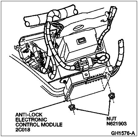
91 file://c:\tso\tsocache\vdtom_5368\svk~us~en~file=svk69a19.htm~gen~ref.htm Page 2 of 2
1998 E-Series Workshop Manual
 SECTION 206-09A: Anti-Lock Control Rear DIAGNOSIS AND TESTING Procedure revision date: 02/08/2000 Anti-Lock Control Refer to Wiring Diagrams Cell 42, Speed Control for schematic and connector information.
Electrical Schematics
 file://c:\tso\tsocache\vdtom_5368\svk~us~en~file=svk69b14.htm~gen~ref.htm Page 1 of 9 Section 06-09B: Brake, 4-Wheel Anti-Lock DIAGNOSIS AND TESTING 1997 Ranger Workshop Manual Electrical Schematics Brake,
1994 Bronco/Econoline/F-Series
 Page 1 of 8 Section 10-03: Speed Control System, Electronic DIAGNOSIS AND TESTING 1994 Bronco/Econoline/F-Series Workshop Manual Electrical Schematics Speed Control System Econoline 1 10 (LG/R) Stoplamp
 Page 1 of 29 Section 04-05: Suspension, Computer Controlled 1997 Town Car Workshop Manual DIAGNOSIS AND TESTING Procedure revision date: 05/16/2000 Suspension, Computer Controlled Inspection and Verification
2000 F-150 Workshop Manual
 Page 1 of 14 SECTION 303-06: Starting System 2000 F-150 Workshop Manual DIAGNOSIS AND TESTING Procedure revision date: 06/17/1999 Starting System Refer to Wiring Diagrams Cell 20, Starting System for schematic
2005 Mustang Workshop Manual
 Page 1 of 6 SECTION 417-01: Exterior Lighting 2005 Mustang Workshop Manual DIAGNOSIS AND TESTING Procedure revision date: 07/23/2009 Stoplamps Printable View (190 KB) Refer to Wiring Diagrams Cell 90 for
 Page 1 of 58 SECTION 413-01: Instrument Cluster DIAGNOSIS AND TESTING Procedure revision date: 03/03/2000 Instrument Cluster Refer to Wiring Diagrams Cell 60, Instrument Cluster (Analog) for schematic
ANTI-LOCK BRAKE SYSTEM
 ANTI-LOCK BRAKE SYSTEM 1993 Mitsubishi Diamante 1993 BRAKES Mitsubishi - Anti-Lock Brake System Diamante DESCRIPTION The Anti-Lock BRAKE SYSTEM (ABS) is designed to prevent wheel lock-up during heavy braking.
BASIC BRAKE SYSTEM GROUP 35A 35A-1 CONTENTS GENERAL DESCRIPTION... 35A-3 BASIC BRAKE SYSTEM DIAGNOSIS 35A-6
 35A-1 GROUP 35A BASIC BRAKE SYSTEM CONTENTS GENERAL DESCRIPTION......... 35A-3 DIAGNOSIS 35A-6 INTRODUCTION..................... 35A-6 DIAGNOSTIC TROUBLESHOOTING STRATEGY......................... 35A-6
DIAGNOSIS AND TESTING
 206-09-1 Vehicle Dynamic Systems 206-09-1 DIAGNOSIS AND TESTING Anti-Lock Control Traction Control and Stability Assist Special Tool(s) Principles of Operation 73III Automotive Meter 105-R0057 or equivalent
ANTI-LOCK BRAKE SYSTEM - REAR WHEEL
 ANTI-LOCK BRAKE SYSTEM - REAR WHEEL 1994 Nissan Pickup 1994 BRAKES Nissan - Rear Anti-Lock Pathfinder, Pickup DESCRIPTION In 2WD mode, Rear Anti-Lock Brake System (RABS) helps the driver to maintain steering
 Page 1 of 50 Section 412-00: Climate Control System General Information DIAGSIS AND TESTING 1997 Mark VIII Workshop Manual Climate Control System Special Service Tool(s) 73 Digital Multimeter 105-R0051
2002 F-150 Workshop Manual
 Page 1 of 23 SECTION 310-03: Speed Control 2002 F-150 Workshop Manual DIAGNOSIS AND TESTING Procedure revision date: 08/07/2006 Speed Control Refer to Wiring Diagrams Cell 31, Speed Control for schematic
2003 F-Super Duty /Excursion Workshop Manual
 3//2011 SECTION 310-03: Speed Control 2003 F-Super Duty 250-550/Excursion Workshop Manual DIAGNOSIS AND TESTING Procedure revision date: 08/01/2006 Speed Control Printable View (331 KB) Refer to Wiring
NOTE: The Smart Junction Box (SJB) is also known as the Generic Electronic Module (GEM).
 is also known as the Generic Electronic Module (GEM).") SECTION 417-01: Exterior Lighting 2009 Mustang Workshop Manual DIAGNOSIS AND TESTING Procedure revision date: 05/23/2008 Reversing Lamps Special Tool(s) 73III Automotive Meter 105-R0057 or equivalent Vehicle
SECTION 417-01: Exterior Lighting 2009 Mustang Workshop Manual DIAGNOSIS AND TESTING Procedure revision date: 05/23/2008 Reversing Lamps Special Tool(s) 73III Automotive Meter 105-R0057 or equivalent Vehicle
1999 Toyota RAV ACCESSORIES & EQUIPMENT Cruise Control Systems - RAV4
 1999 ACCESSORIES & EQUIPMENT Cruise Control Systems - RAV4 DESCRIPTION WARNING: Deactivate air bag system before performing any service operation. See AIR BAG RESTRAINT SYSTEMS article. DO NOT apply electrical
ANTI-LOCK BRAKING SYSTEM (ABS)
") 35B-1 GROUP 35B ANTI-LOCK BRAKING SYSTEM (ABS) CONTENTS GENERAL DESCRIPTION 35B-2 35B-5 INTRODUCTION TO 35B-5 ABS DIAGNOSTIC TROUBLESHOOTING STRATEGY 35B-5 DIAGNOSTIC FUNCTION 35B-6 DIAGNOSTIC TROUBLE
35B-1 GROUP 35B ANTI-LOCK BRAKING SYSTEM (ABS) CONTENTS GENERAL DESCRIPTION 35B-2 35B-5 INTRODUCTION TO 35B-5 ABS DIAGNOSTIC TROUBLESHOOTING STRATEGY 35B-5 DIAGNOSTIC FUNCTION 35B-6 DIAGNOSTIC TROUBLE
STARTING SYSTEMS 8B - 1 STARTING SYSTEMS CONTENTS
 TJ STARTING SYSTEMS 8B - 1 STARTING SYSTEMS CONTENTS page DESCRIPTION AND OPERATION STARTER MOTOR... 2 STARTER RELAY... 3 STARTING SYSTEM... 1 DIAGNOSIS AND TESTING STARTER MOTOR... 8 STARTER MOTOR NOISE
1995 Aerostar/Ranger/Explorer
 95 Aerostar/Ranger/Explorer Section 13-01: Instrument Cluster, Conventional DIAGNOSIS AND TESTING 95 Aerostar/Ranger/Explorer Workshop Manual Pinpoint Tests PINPOINT TEST A: FUEL LEVEL READS INACCURATELY
ANTI-LOCK BRAKING SYSTEM (ABS)
") 35B-1 GROUP 35B ANTI-LOCK BRAKING SYSTEM (ABS) CONTENTS GENERAL DESCRIPTION......... 35B-2................ 35B-4 INTRODUCTION TO ANTI-LOCK BRAKING SYSTEM DIAGNOSIS................ 35B-4 ABS DIAGNOSTIC
35B-1 GROUP 35B ANTI-LOCK BRAKING SYSTEM (ABS) CONTENTS GENERAL DESCRIPTION......... 35B-2................ 35B-4 INTRODUCTION TO ANTI-LOCK BRAKING SYSTEM DIAGNOSIS................ 35B-4 ABS DIAGNOSTIC
2001 Chevrolet Corvette ACCESSORIES & EQUIPMENT Cruise Control Systems - Corvette
 2001 ACCESSORIES & EQUIPMENT Cruise Control Systems - Corvette DESCRIPTION Cruise control is a speed control system that maintains a desired vehicle speed under normal driving conditions. Steep grades
GROUP 35A 35A-1 CONTENTS GENERAL DESCRIPTION... 35A-3 BASIC BRAKE SYSTEM DIAGNOSIS 35A-6 HYDRAULIC BRAKE BOOSTER (HBB) DIAGNOSIS...
 DIAGNOSIS...") 35A-1 GROUP 35A CONTENTS GENERAL DESCRIPTION......... 35A-3 DIAGNOSIS 35A-6 INTRODUCTION..................... 35A-6 DIAGNOSTIC TROUBLESHOOTING STRATEGY......................... 35A-6 SYMPTOM CHART...................
35A-1 GROUP 35A CONTENTS GENERAL DESCRIPTION......... 35A-3 DIAGNOSIS 35A-6 INTRODUCTION..................... 35A-6 DIAGNOSTIC TROUBLESHOOTING STRATEGY......................... 35A-6 SYMPTOM CHART...................
1999 F-Super Duty Workshop Manual
 Page 1 of 69 SECTION 413-01: Instrument Cluster 1999 F-Super Duty 250-550 Workshop Manual DIAGNOSIS AND TESTING Procedure revision date: 09/27/2002 Instrument Cluster Refer to Wiring Diagrams Cell 60 (F-53
TRACTION CONTROL SYSTEM (TCL)
") 35C-1 GROUP 35C TRACTION CONTROL SYSTEM (TCL) CONTENTS GENERAL DESCRIPTION 35C-2 DIAGNOSIS 35C-4 INTRODUCTION TO TRACTION CONTROL SYSTEM DIAGNOSIS 35C-4 TCL DIAGNOSTIC TROUBLESHOOTING STRATEGY 35C-4 DIAGNOSTIC
35C-1 GROUP 35C TRACTION CONTROL SYSTEM (TCL) CONTENTS GENERAL DESCRIPTION 35C-2 DIAGNOSIS 35C-4 INTRODUCTION TO TRACTION CONTROL SYSTEM DIAGNOSIS 35C-4 TCL DIAGNOSTIC TROUBLESHOOTING STRATEGY 35C-4 DIAGNOSTIC
DESCRIPTION & OPERATION
 DESCRIPTION & OPERATION 1998-99 SUSPENSION Electronic - Real Time Damping - Corvette The Real Time Damping (RTD) system automatically controls vehicle ride by independently controlling a damper solenoid
1998 F-150/250 Workshop Manual
 Page 1 of 74 SECTION 308-07A: Transfer Case General Information DIAGNOSIS AND TESTING Procedure revision date: 12/04/2002 Transfer Case ESOF Refer to Wiring Diagrams Cell 34, Electric Shift Control for
ALTERNATOR REQUESTED INFORMATION. Vehicles With Dual Generator [ Engine Mount - LH ] 2007 Ford Pickup 6.0L Eng F350 Super Duty
![ALTERNATOR REQUESTED INFORMATION. Vehicles With Dual Generator [ Engine Mount - LH ] 2007 Ford Pickup 6.0L Eng F350 Super Duty](/thumbs/72/66590437.jpg "ALTERNATOR REQUESTED INFORMATION. Vehicles With Dual Generator [ Engine Mount - LH ] 2007 Ford Pickup 6.0L Eng F350 Super Duty") ALTERNATOR 2007 Ford Pickup 6.0L Eng F350 Super Duty REQUESTED INFORMATION Vehicles With Dual Generator [ Engine Mount - LH ] Fig 1: Rotating Drive Belt Tensioner Clockwise 1. Remove the accessory drive
ALTERNATOR 2007 Ford Pickup 6.0L Eng F350 Super Duty REQUESTED INFORMATION Vehicles With Dual Generator [ Engine Mount - LH ] Fig 1: Rotating Drive Belt Tensioner Clockwise 1. Remove the accessory drive
ANTI-LOCK BRAKING SYSTEM (ABS)
") 35B-1 GROUP 35B ANTI-LOCK BRAKING SYSTEM (ABS) CONTENTS GENERAL DESCRIPTION 35B-2 DIAGNOSIS 35B-4 INTRODUCTION TO ANTI-LOCK BRAKING SYSTEM DIAGNOSIS 35B-4 ABS DIAGNOSTIC TROUBLESHOOTING STRATEGY 35B-4
35B-1 GROUP 35B ANTI-LOCK BRAKING SYSTEM (ABS) CONTENTS GENERAL DESCRIPTION 35B-2 DIAGNOSIS 35B-4 INTRODUCTION TO ANTI-LOCK BRAKING SYSTEM DIAGNOSIS 35B-4 ABS DIAGNOSTIC TROUBLESHOOTING STRATEGY 35B-4
SCHEMATIC AND ROUTING DIAGRAMS
 2004 ACCESSORIES & EQUIPMENT Theft Deterrent - Corvette SCHEMATIC AND ROUTING DIAGRAMS THEFT DETERRENT SYSTEM SCHEMATICS Fig. 1: Theft Deterrent Relay, Security Indicator, Lighting and Horn References
Gateway 505/605 Symptom Flow Chart Lift Interlock
 An ISO 9001:2008 Registered Company Gateway 505/605 Symptom Flow Chart Lift Interlock Begin diagnosis by performing the system post installation instructions notating system operation while doing checks.
ANTI-LOCK BRAKING SYSTEM (ABS)
") 35B-1 GROUP 35B ANTI-LOCK BRAKING SYSTEM (ABS) CONTENTS GENERAL DESCRIPTION......... 35B-2 ANTI-SKID BRAKING SYSTEM (ABS) DIAGNOSIS.................... 35B-3 INTRODUCTION TO ANTI-LOCK BRAKE SYSTEM DIAGNOSIS................
35B-1 GROUP 35B ANTI-LOCK BRAKING SYSTEM (ABS) CONTENTS GENERAL DESCRIPTION......... 35B-2 ANTI-SKID BRAKING SYSTEM (ABS) DIAGNOSIS.................... 35B-3 INTRODUCTION TO ANTI-LOCK BRAKE SYSTEM DIAGNOSIS................
DIAGNOSIS AND TESTING
 308-07A-1 DIAGNOSIS AND TESTING Electronic Shift Visual Inspection Chart Mechanical Electrical 308-07A-1 Refer to Wiring Diagrams Cell 34 for schematic and Halfshafts Junction box (JB) mini connector information.
SUPPLEMENTAL RESTRAINTS SYSTEM
 SECTION 8B SUPPLEMENTAL RESTRAINTS SYSTEM CAUTION: Disconnect the negative battery cable before removing or installing any electrical unit or when a tool or equipment could easily come in contact with
SECTION Handles, Locks, Latches and Entry Systems
 501-14-i Handles, Locks, Latches and Entry Systems 501-14-i SECTION 501-14 Handles, Locks, Latches and Entry Systems CONTENTS PAGE DIAGNOSIS AND TESTING Handles, Locks, Latches and Entry Systems... 501-14-2
DIAGNOSIS AND TESTING
 501-14-1 Handles, Locks, Latches and Entry Systems 501-14-1 DIAGNOSIS AND TESTING Locks, Latches and Entry Systems Refer to Wiring Diagrams Cell 117 for schematic and connector information. Special Tool(s)
2003 Explorer/Mountaineer Workshop Manual
 Page 1 of 11 SECTION 414-00: Battery and Charging System 2003 Explorer/Mountaineer Workshop Manual DIAGNOSIS AND TESTING Procedure revision date: 06/18/2002 Charging System Printable View (257 KB) Refer
SECTION Exterior Lighting
 417-01-i Exterior Lighting 417-01-i SECTION 417-01 Exterior Lighting CONTENTS PAGE DIAGNOSIS AND TESTING Headlamps... 417-01-2 Principles of Operation... 417-01-2 Inspection and Verification... 417-01-3
SECTION Instrument Cluster and Panel Illumination
 413-00-i Instrument Cluster and Panel Illumination 413-00-i SECTION 413-00 Instrument Cluster and Panel Illumination CONTENTS PAGE DIAGNOSIS AND TESTING Instrument Cluster and Panel Illumination... 413-00-2
GRD502-B Flow Chart 02/05/09
 PINPOINT TEST A: NO PROVE OUT OF ANY LEDs prove out (all LED's light up) of the LED's when module power is applied or module "wakes up", indicates that: - the Guardian module does not have power. - the
2001 Focus Workshop Manual
 Page 1 of 24 SECTION 413-01: Instrument Cluster 2001 Focus Workshop Manual DIAGNOSIS AND TESTING Procedure revision date: 04/23/2002 Instrument Cluster Refer to Wiring Diagrams Section 413-01 for schematic
 2//2011 Section 206-05: Parking Brake and Actuation DIAGSIS AND TESTING Workshop Manual Parking Brake and Actuation Electrical Schematic Reference(s) Refer to Electrical and Vacuum Troubleshooting Manual,
2002 Dodge Intrepid ES ACCESSORIES & EQUIPMENT Anti-Theft Systems - Concorde, Intrepid & 300M
 DESCRIPTION SENTRY KEY IMMOBILIZER SYSTEM 2002-03 ACCESSORIES & EQUIPMENT Anti-Theft Systems - Concorde, Intrepid & 300M CAUTION: Large metallic objects, or items such as magnetic pass-keys, may cause
2007 Chevrolet Corvette STEERING Steering Wheel and Column - Corvette. Steering Wheel and Column - Corvette
 2007 STEERING Steering Wheel and Column - Corvette SPECIFICATIONS FASTENER TIGHTENING SPECIFICATIONS Fastener Tightening Specifications Specification Application Metric English Actuator Retaining Screws
CRUISE CONTROL SYSTEM
 CRUISE CONTROL SYSTEM 1994 Toyota Celica 1994 ACCESSORIES & EQUIPMENT Toyota Motor Sales, U.S.A., Inc. - Cruise Control Systems Celica DESCRIPTION Cruise control system consists of Cruise Control Electronic
VEHICLE SPEED CONTROL SYSTEM
 J VEHICLE SPEED CONTROL SYSTEM 8H - 1 VEHICLE SPEED CONTROL SYSTEM CONTENTS page DIAGNOSIS... 2 GENERAL INFORMATION... 1 page SERVICE PROCEDURES... 9 GENERAL INFORMATION The vehicle speed control system
1999 Expedition/Navigator Workshop Manual
 Page 1 of 16 SECTION 419-01: Anti-Theft PATS 1999 Expedition/Navigator Workshop Manual DIAGNOSIS AND TESTING Procedure revision date: 07/01/1998 Anti-Theft Passive Anti-Theft System (PATS) Refer to Wiring
1994 Aerostar/Ranger/Explorer
 http://www.fordtechservice.dealerconnection.com/pubs/content/~wsrk/~mus~len//... Section 13-01B: Instrument Cluster, Conventional DIAGNOSIS AND TESTING 1994 Aerostar/Ranger/Explorer Workshop Manual Pinpoint
TRANSMISSION - NGC. Symptom: P0706-CHECK SHIFTER SIGNAL. When Monitored and Set Condition:
 Symptom: P0706-CHECK SHIFTER SIGNAL When Monitored and Set Condition: P0706-CHECK SHIFTER SIGNAL When Monitored: Continuously with the ignition on. Set Condition: After 3 occurrences in one ignition cycle
2001 Cougar Workshop Manual
 Page 1 of 7 SECTION 303-06: Starting System 2001 Cougar Workshop Manual DIAGNOSIS AND TESTING Procedure revision date: 09/14/2001 Starting System Refer to Wiring Diagrams Section 303-06 for schematic and
1993 Ford Escort. G - TESTS W/CODES - EEC-IV (1.9L)' '1993 ENGINE PERFORMANCE Ford Motor Co. - Self-Diagnostics - EEC-IV
' '1993 ENGINE PERFORMANCE Ford Motor Co. - Self-Diagnostics - EEC-IV") CIRCUIT TEST J - FUEL PUMP CIRCUIT (RELAY & INERTIA SWITCH) Diagnostic Aids When ignition switch is in the ON or START position, the PCM connects FUEL PUMP circuit (PCM terminal No. 22) to ground. The
CIRCUIT TEST J - FUEL PUMP CIRCUIT (RELAY & INERTIA SWITCH) Diagnostic Aids When ignition switch is in the ON or START position, the PCM connects FUEL PUMP circuit (PCM terminal No. 22) to ground. The
DIAGNOSIS AND TESTING Procedure revision date: 06/21/2000
 2001 F-350 Applies to: Gasoline Report a problem with this article Subarticles Inspection and Verification Symptom Chart Pinpoint Tests Component Tests SECTION 303-06A: Starting System Gasoline Engines
DTC P0341 Camshaft Position (CMP) Sensor Performance
 Sensor Performance") Page 1 of 7 1997 Buick Riviera Aurora, Riviera (VIN G) Service Manual Document ID: 53298 DTC P0341 Camshaft Position (CMP) Sensor Performance Circuit Description The camshaft position PCM input is produced
Page 1 of 7 1997 Buick Riviera Aurora, Riviera (VIN G) Service Manual Document ID: 53298 DTC P0341 Camshaft Position (CMP) Sensor Performance Circuit Description The camshaft position PCM input is produced
 Page 1 of 8 HW7 DTC P1443: CHECK THE VOLTAGE ON THE PURGE FLOW (PF) SENSOR CIRCUIT VOLTAGE WITH ENGINE RUNNING Continuous Memory Diagnostic Trouble Code (DTC) P1443 indicates an incorrect evaporative system
DS: Air Conditioning Pressure (ACP) Transducer Sensor
 Transducer Sensor") 2009 PCED Gasoline Engines SECTION 5: Pinpoint Tests Procedure revision date: 08/12/2009 DS: Air Conditioning Pressure () Transducer Sensor DS: Introduction DS1 CHECK FOR DIAGNOSTIC TROUBLE CODES (DTCS)
2009 PCED Gasoline Engines SECTION 5: Pinpoint Tests Procedure revision date: 08/12/2009 DS: Air Conditioning Pressure () Transducer Sensor DS: Introduction DS1 CHECK FOR DIAGNOSTIC TROUBLE CODES (DTCS)
DESCRIPTION & OPERATION
 DESCRIPTION & OPERATION ANTI-LOCK BRAKING 1998-99 BRAKES Anti-Lock/TCS - Corvette The Anti-Lock Brake System (ABS) and Traction Control System (TCS) increases vehicle control during severe deceleration
POWER LOCK SYSTEMS 8P - 1 POWER LOCK SYSTEMS TABLE OF CONTENTS
 AN POWER LOCK SYSTEMS 8P - 1 POWER LOCK SYSTEMS TABLE OF CONTENTS page GENERAL INFORMATION INTRODUCTION...1 POWER LOCK SYSTEM...1 REMOTE KEYLESS ENTRY SYSTEM...1 DESCRIPTION AND OPERATION CENTRAL TIMER
2002 Cougar Workshop Manual
 SECTION 413-01: Instrument Cluster 2002 Cougar Workshop Manual DIAGNOSIS AND TESTING Procedure revision date: 12/10/2001 Instrument Cluster Refer to Wiring Diagrams Cell 60 for schematic and connector
Instrument Cluster (IC)
") PINPOINT TEST F : THE TACHOME... PINPOINT TEST F : THE TACHOMETER IS INOPERATIVE (INSTRUMENT CLUSTER) 413 01 Instrument Cluster 2004 Ranger DIAGNOSIS AND TESTING Procedure revision date: 09/23/2008 Instrument
PINPOINT TEST F : THE TACHOME... PINPOINT TEST F : THE TACHOMETER IS INOPERATIVE (INSTRUMENT CLUSTER) 413 01 Instrument Cluster 2004 Ranger DIAGNOSIS AND TESTING Procedure revision date: 09/23/2008 Instrument
ANTI-LOCK BRAKE SYSTEM
 ANTI-LOCK BRAKE SYSTEM 1995 Chevrolet Tahoe 1995 BRAKES General Motors Corp. - Anti-Lock - 4WAL Chevrolet: Pickup, Tahoe GMC: Sierra, Suburban, Yukon MODEL IDENTIFICATION Vehicle model can be identified
17. ANTI-LOCK BRAKE SYSTEM (ABS; CBF1000A)
") 17. ANTI-LOCK BRAKE SYSTEM (ABS; CBF1000A) ABS SYSTEM LOCATION 17-2 ABS SYSTEM DIAGRAM 17-3 SERVICE INFORMATION 17-4 ABS CONNECTOR LOCATIONS 17-5 ABS TROUBLESHOOTING INFORMATION 17-7 ABS PROBLEM CODE INDEX
17. ANTI-LOCK BRAKE SYSTEM (ABS; CBF1000A) ABS SYSTEM LOCATION 17-2 ABS SYSTEM DIAGRAM 17-3 SERVICE INFORMATION 17-4 ABS CONNECTOR LOCATIONS 17-5 ABS TROUBLESHOOTING INFORMATION 17-7 ABS PROBLEM CODE INDEX
SECTION Anti-Lock Brake System (ABS) and Stability Control
 and Stability Control") 206-09-i Anti-Lock Brake System (ABS) and Stability Control 206-09-i SECTION 206-09 Anti-Lock Brake System (ABS) and Stability Control CONTENTS PAGE DIAGNOSIS AND TESTING Anti-Lock Control... 206-09-2
206-09-i Anti-Lock Brake System (ABS) and Stability Control 206-09-i SECTION 206-09 Anti-Lock Brake System (ABS) and Stability Control CONTENTS PAGE DIAGNOSIS AND TESTING Anti-Lock Control... 206-09-2
On Board Diagnostics II A PCED
 1998 PCED On Board Diagnostics II A SECTION 5A: Pinpoint Tests HA: Natural Gas Fuel Control HA: Introduction HA30 DTCS P05, P0141, P0155 AND P0161: HO2S HEATER SIGNAL CIRCUIT IS OPEN, SHORTED TO GROUND,
On Board Diagnostics II PCED
 Page 1 of 5 1999 PCED On Board Diagnostics II SECTION 5: Pinpoint Tests HD: Misfire Detection Monitor HD: Introduction HD1 DTC P0301-P0310: CHECK FOR NO LOW FUEL te: Running out of fuel can turn on the
DESCRIPTION & OPERATION
 ANTI-THEFT SYSTEM 1998 ACCESSORIES & EQUIPMENT General Motors Corp. - Anti-Theft System DESCRIPTION & OPERATION WARNING: Deactivate air bag system before performing any service operation. See AIR BAG RESTRAINT
BASIC DIAGNOSTIC PROCEDURES
 BASIC DIAGNOSTIC PROCEDURES 2001 Chevrolet Camaro 2001 ENGINE PERFORMANCE Basic Diagnostic Procedures - Cars Except Metro & Prizm MODEL IDENTIFICATION MODEL IDENTIFICATION Body Code (1) Model C... Park
DTC P0300-P0308. Diagnostic Instructions. DTC Descriptors. Circuit/System Description. Conditions for Running the DTC
 Page 1 of 5 2009 GMC Truck Sierra - 2WD Sierra, Silverado (VIN C/K) Service Manual Engine Engine Mechanical - 4.8L, 5.3L, 6.0L, 6.2L, or 7.0L Description and Operation DTC P0300-P0308 Diagnostic Instructions
DTC P0341 Camshaft Position (CMP) Sensor Performance
 Sensor Performance") Page 1 of 5 1999 Buick Century Century, Regal VIN W Service Manual Document ID: 345654 DTC P0341 Camshaft Position (CMP) Sensor Performance Circuit Description During cranking, the Ignition Control Module
Page 1 of 5 1999 Buick Century Century, Regal VIN W Service Manual Document ID: 345654 DTC P0341 Camshaft Position (CMP) Sensor Performance Circuit Description During cranking, the Ignition Control Module
2004 Ranger Workshop Manual
 Page 1 of 6 SECTION 413-00: Instrument Cluster and Panel Illumination 2004 Ranger Workshop Manual DIAGNOSIS AND TESTING Procedure revision date: 10/30/2003 Instrument Cluster and Panel Illumination Printable
HOW TO PROCEED WITH TROUBLESHOOTING
 2005 BRAKES Anti-Lock Brake System With Electronic Brake Force Distribution (EBD) - Diagnostics - RAV4 HOW TO PROCEED WITH TROUBLESHOOTING Troubleshoot in accordance with the following procedures. Fig.
1998 Expedition/Navigator Workshop Manual
 Page 1 of 64 SECTION 308-07A: Transfer Case General Information DIAGNOSIS AND TESTING Procedure revision date: 05/06/2002 Transfer Case Refer to Wiring Diagrams Cell 34 (Expedition, Navigator), All-Wheel
SECTION Interior Lighting
 417-02-i Interior Lighting 417-02-i SECTION 417-02 Interior Lighting CONTENTS PAGE DIAGNOSIS AND TESTING Interior Lighting... 417-02-2 Principles of Operation... 417-02-2 Inspection and Verification...
DR: Camshaft Position (CMP) Sensor
 Sensor") 2007 PCED On Board Diagnostics SECTION 5: Pinpoint Tests Procedure revision date: 03/29/2006 DR: Camshaft Position () Sensor DR: Introduction DR1 CHECK FOR DIAGNOSTIC TROUBLE CODES (DTCS) Are DTCs P0340,
2007 PCED On Board Diagnostics SECTION 5: Pinpoint Tests Procedure revision date: 03/29/2006 DR: Camshaft Position () Sensor DR: Introduction DR1 CHECK FOR DIAGNOSTIC TROUBLE CODES (DTCS) Are DTCs P0340,
ON BOARD DIAGNOSTIC SYSTEM DESCRIPTION Self-diagnosis. Self-diagnosis BR-44 FUNCTION SELF-DIAGNOSIS PROCEDURE ABS
 Self-diagnosis ON BOARD DIAGNOSTIC SYSTEM DESCRIPTION Self-diagnosis FUNCTION NABR0095 NABR0095S01 When a problem occurs in the, the warning lamp on the instrument panel comes on. To start the self-diagnostic
Intake Air Temperature (IAT) Sensor
 Sensor") Page 1 of 5 Year = 2011 Model = Mustang Engine = 5.0L VIN = IDS Version = t Available Intake Air Temperature (IAT) Sensor This pinpoint test is intended to diagnose the following: IAT sensor (12A697) integrated
Page 1 of 5 Year = 2011 Model = Mustang Engine = 5.0L VIN = IDS Version = t Available Intake Air Temperature (IAT) Sensor This pinpoint test is intended to diagnose the following: IAT sensor (12A697) integrated
SECTION 12M - SUPPLEMENTAL RESTRAINT SYSTEM (VERSIONS 8.0 AND 8.1)
") SECTION 12M - SUPPLEMENTAL RESTRAINT SYSTEM (VERSIONS 8.0 AND 8.1) IMPORTANT Before performing any Service Operation or other procedure described in this Section, refer to Section 00 CAUTIONS AND NOTES
SECTION 12M - SUPPLEMENTAL RESTRAINT SYSTEM (VERSIONS 8.0 AND 8.1) IMPORTANT Before performing any Service Operation or other procedure described in this Section, refer to Section 00 CAUTIONS AND NOTES
DIAGNOSIS AND TESTING
 417-01-1 Exterior Lighting 417-01-1 DIAGNOSIS AND TESTING Visual Inspection Chart Turn Signal and Hazard Lamps Refer to Wiring Diagrams Cell 90 for schematic and Mechanical Electrical connector information.
DTC P1655 Evaporative Emission (EVAP) Purge Solenoid Control Circuit
 Purge Solenoid Control Circuit") Page 1 of 5 1997 Pontiac Grand Am Achieva, Grand Am, Skylark (VIN N) Service Manual Document ID: 58460 DTC P55 Evaporative Emission (EVAP) Purge Solenoid Control Circuit Circuit Description Output Driver
Page 1 of 5 1997 Pontiac Grand Am Achieva, Grand Am, Skylark (VIN N) Service Manual Document ID: 58460 DTC P55 Evaporative Emission (EVAP) Purge Solenoid Control Circuit Circuit Description Output Driver
Printable View Page 1 of 18 11/26/2013 Year = 2011 Model = E
 Page 1 of 18 Year = 2011 Model = Escape Engine = VIN = IDS Version = t Available Misfire Detection Monitor WARNING: Crown Victoria Police Interceptor vehicles equipped with fire suppression system, refer
GROUP 17 CONTENTS WARNINGS REGARDING SERVICING OF SUPPLEMENTAL RESTRAINT SYSTEM (SRS) EQUIPPED VEHICLES
 EQUIPPED VEHICLES") 17-1 GROUP 17 CONTENTS ENGINE CONTROL 17-4 GENERAL DESCRIPTION 17-4 ENGINE CONTROL SYSTEM DIAGNOSIS 17-4 INTRODUCTION TO ENGINE CONTROL SYSTEM DIAGNOSIS 17-4 ENGINE CONTROL SYSTEM DIAGNOSTIC TROUBLESHOOTING
17-1 GROUP 17 CONTENTS ENGINE CONTROL 17-4 GENERAL DESCRIPTION 17-4 ENGINE CONTROL SYSTEM DIAGNOSIS 17-4 INTRODUCTION TO ENGINE CONTROL SYSTEM DIAGNOSIS 17-4 ENGINE CONTROL SYSTEM DIAGNOSTIC TROUBLESHOOTING
DIAGNOSIS AND TESTING
 307-05-1 Automatic Transaxle/Transmission External Controls 307-05-1 DIAGNOSIS AND TESTING Visual Inspection Chart External Controls Mechanical Electrical Refer to Wiring Diagrams Cell 37 for schematic
1998 Crown Victoria/Grand Marquis Workshop Manual
 Section 17-01: Lighting, Exterior Workshop Manual DIAGNOSIS AND TESTING Procedure revision date: 03/16/1998 Headlamps (With Autolamps) Inspection and Verification 1. Verify the customer's concern by operating
2003 Crown Victoria/Grand Marquis/Marauder Workshop Manual
 Page 1 of 9 SECTION 413-00: Instrument Cluster and Panel Illumination 2003 Crown Victoria/Grand Marquis/Marauder Workshop Manual DIAGNOSIS AND TESTING Procedure revision date: 02/25/2004 Instrument Cluster
1999 Mercury Cougar ACCESSORIES & EQUIPMENT' 'Passive Anti-Theft Systems - Cougar 1999 ACCESSORIES & EQUIPMENT
 DESCRIPTION 1999 ACCESSORIES & EQUIPMENT Passive Anti-Theft Systems - Cougar Passive Anti-Theft System (PATS) is available on some vehicles. The system is passive in that it does not require any activity
HD: Misfire Detection Monitor
 2009 PCED Gasoline Engines SECTION 5: Pinpoint Tests Procedure revision date: 12/10/2008 HD: Misfire Detection Monitor HD: Introduction HD1 CHECK FOR DIAGNOSTIC TROUBLE CODES (DTCS) Are DTCs P0300, P0301,
1998 ENGINE PERFORMANCE. General Motors Corp. - Basic Diagnostic Procedures - 5.7L
 INTRODUCTION 1998 ENGINE PERFORMANCE General Motors Corp. - Basic Diagnostic Procedures - 5.7L The following diagnostic steps will help prevent overlooking a simple problem. This is also where to begin
Cooling Fan (CF) Module Connector
 Module Connector") Page 1 of 14 Year = 2006 Model = Town Car Engine = VIN = IDS Version = 92.01 (IDS-92.01) Variable Speed Electric Cooling Fan WARNING: Crown Victoria Police Interceptor vehicles equipped with fire suppression
Page 1 of 14 Year = 2006 Model = Town Car Engine = VIN = IDS Version = 92.01 (IDS-92.01) Variable Speed Electric Cooling Fan WARNING: Crown Victoria Police Interceptor vehicles equipped with fire suppression
Fuel Pump Electrical Circuit Diagnosis
 Page 1 of 6 Document ID# 599891 2000 Chevrolet Camaro Feedback Print Fuel Pump Electrical Circuit Diagnosis Circuit Description When the ignition switch is ON, the powertrain control
 Page 1 of 54 412-00 Climate Control System General Information and Diagnostics 2006 Crown Victoria/Grand Marquis DIAGNOSIS AND TESTING Procedure revision date: 12/23/2008 Climate Control System Printable
CHARGING SYSTEM 8C - 1 CHARGING SYSTEM CONTENTS
 TJ CHARGING SYSTEM 8C - 1 CHARGING SYSTEM CONTENTS page DESCRIPTION AND OPERATION BATTERY TEMPERATURE SENSOR... 2 CHARGING SYSTEM OPERATION... 1 ELECTRONIC VOLTAGE REGULATOR... 2 GENERATOR... 1 DIAGNOSIS
Pinpoint Tests OSC Equipped Vehicle
 SECTION 307-01: Automatic Transaxle/Transmission 5R55S 2009 Mustang Workshop Manual DIAGNOSIS AND TESTING Procedure revision date: 11/19/2008 Pinpoint Tests OSC Equipped Vehicle Special Tool(s) 73 III
ANTI-SKID BRAKING SYSTEM (ABS)
") GROUP 35B ANTI-SKID BRAKING SYSTEM (ABS) CONTENTS GENERAL INFORMATION........ 35B-2 SERVICE SPECIFICATIONS....... 35B-4 SPECIAL TOOLS................ 35B-5............ 35B-6 STANDARD FLOW OF DIAGNOSTIC................
GROUP 35B ANTI-SKID BRAKING SYSTEM (ABS) CONTENTS GENERAL INFORMATION........ 35B-2 SERVICE SPECIFICATIONS....... 35B-4 SPECIAL TOOLS................ 35B-5............ 35B-6 STANDARD FLOW OF DIAGNOSTIC................
AUTO TRANS DIAGNOSIS - 4T65-E
 AUTO TRANS DIAGNOSIS - 4T65-E 1998 Pontiac Bonneville 1997-98 AUTOMATIC TRANSMISSIONS General Motors - 4T65-E Electronic Controls Buick; LeSabre, Park Avenue, Regal, Riviera Chevrolet; Lumina, Monte Carlo
2001 Explorer Sport/Sport Trac Workshop Manual
 Page 1 of 11 SECTION 303-06: Starting System 2001 Explorer Sport/Sport Trac Workshop Manual DIAGNOSIS AND TESTING Procedure revision date: 03/18/2004 Starting System Refer to Wiring Diagrams Cell 20 for
05/01/06 1er mai 2006 Cruise Control - Diagnostic Updates General Service Procedure Service Procedure Speed Control Diagnostic Tips Additional
 05/01/06 1er mai 2006 General Service Procedure Service Procedure Speed Control Diagnostic Tips Additional Reference Information SPEED CONTROL DIAGNOSTICS - W/O SCP FORD: 2000-2003 Escort 2000-2004 Crown
2003 Ford Explorer - Diagnostics > Diagnostic Routines > Powertrain > On Board Diagnostics > P... Page 1 of 18
 2003 Ford Explorer - Diagnostics > Diagnostic Routines > Powertrain > On Board Diagnostics > P... Page 1 of 18 2003 Ford Explorer : Diagnostics > Diagnostic Routines > Powertrain > On Board Diagnostics
Powertrain DTC Summaries EOBD
 Powertrain DTC Summaries Quick Reference Diagnostic Guide Jaguar X-TYPE 2.0 L 2002.25 Model Year Refer to page 2 for important information regarding the use of Powertrain DTC Summaries. Jaguar X-TYPE 2.0
CHARGING SYSTEM 8C - 1 CHARGING SYSTEM CONTENTS
 ZG CHARGING SYSTEM 8C - 1 CHARGING SYSTEM CONTENTS page GENERAL INFORMATION OVERVIEW... 1 DESCRIPTION AND OPERATION BATTERY TEMPERATURE SENSOR... 2 CHARGING SYSTEM OPERATION... 1 ELECTRONIC VOLTAGE REGULATOR...
On Board Diagnostics II A PCED
 Page 1 of 5 1998 PCED On Board Diagnostics II A SECTION 5A: Pinpoint Tests KE: Idle Air Control (IAC) Valve KE: Introduction KE1 IDLE CONCERNS OR STALLS: RUN KOER SELF-TEST AND OUTPUT CONTINUOUS MEMORY
DTC P Shift Solenoid Circuit Electrical
 1998 Pontiac Grand Prix DTC P0753 1-2 Shift Solenoid Circuit Electrical Circuit Description The 1-2 Shift Solenoid Valve Assembly (1-2 SS Valve Assy.) controls the transmission fluid pressure on the 1-2
DX: Engine Coolant Temperature (ECT) Sensor
 Sensor") 2009 PCED Gasoline Engines SECTION 5: Pinpoint Tests Procedure revision date: 12/10/2008 DX: Engine Coolant Temperature (ECT) Sensor DX: Introduction DX1 CHECK FOR DIAGNOSTIC TROUBLE CODES (DTCS) Are DTCs
2009 PCED Gasoline Engines SECTION 5: Pinpoint Tests Procedure revision date: 12/10/2008 DX: Engine Coolant Temperature (ECT) Sensor DX: Introduction DX1 CHECK FOR DIAGNOSTIC TROUBLE CODES (DTCS) Are DTCs