Belimo Resilient Seat Butterfl y Valves HD & L Series Technical Documentation
|
|
|
- Loreen Baldwin
- 5 years ago
- Views:
Transcription


1 Version 11_2_18 NEAR FIELD COMMUNICATION (NFC) ENABLED NFC Available for PR and PKR Actuators Belimo Resilient Seat Butterfl y Valves HD & L Series Technical Documentation
2 Table of Contents Butterfly Valve Nomenclature... 3 Resilient Seat Butterfly Valve Product Range... 4 Features / Benefits... 5 Butterfly Valve Selection... 6 Butterfly Valve Actuators... 8 SY Series Actuators Standard and Industrial Actuation Customize Products Installation Commissioning with Near Field Communication (NFC) Protocol Implementation Conformance Statement (PICS) BACnet Object Description Retrofit PR Replacement of SY Actuator Valve Accessories Frequently Asked Questions (FAQ) Terms and Conditions Tech.Doc - 10/18 - Subject to change. Belimo Aircontrols (USA), Inc. 2
3 Butterfly Valve Nomenclature F6 200 L +PRB UP -3 -T -200 Valve F6 = 2-way F7 = 3-way Valve Size 50 = 2 65 = 2½ 80 = = = = = = = = = = = = 24 Trim Material HDU/LU = 0% Leakage, 50 psi (3 to 10 ) HD = Stainless Disc, Ductile Iron Body, EPDM Liner, 0% Leakage to 200 psi (2 to 6 & 12 ), 150 psi (14 +) L = Stainless Disc, Ductile Iron Body, EPDM Liner, 0% Leakage to 200 psi (8 to 12 ) VIC = Ductile Iron Grooved End Body, Nickel Coated Ductile Iron Disc, 0% Leakage up to 200 psi -150SHP = ANSI Class 150, Stainless Disc, Steel Body, RPTFE Seat, 0% Leakage up to 285 psi -300SHP = ANSI Class 300, Stainless Disc, Steel Body, RPTFE Seat, 0% Leakage up to 600 psi Actuator Type Non-Spring Return ARB, ARX AMB, AMX GMB, GMX GRB, GRX GR/GM... N4(H) DRB, DRX DR... N4(H) PRB, PRX SY Electronic Fail- Safe GKB, GKX DKRB, DKRX DKR...N4(H) PKRX Spring Return AFB, AFX AFRB, AFRX Power Supply -24 = 24 VAC/DC -110 = 110/120 VAC -120 = 120 VAC -230 = 230 VAC UP = VAC or VDC Control -3-X1 = On/Off, Floating Point MFT or MFT-X1 = Multi-Function Technology -S = Built-in Auxiliary Switch N4 = NEMA 4/4X N4H = NEMA 4 with Heater -T = Terminal Block -200 = = 10 L Series Only X models are customizable. Refer to page 13 for programming options. Ordering Example Non-Spring Return Spring Return/Electronic Fail-Safe 2 Pos. Modulating 2 Pos. Modulating 1 Choose the valve actuator combination. NC NO NO/FO NC/FC NO/FC NC/FO F6200L+PRBUP-3-T way Configuration Set Up Required Field Logic Determines Normal Position (Normally Closed) 0.5 VDC/2VDC/4mA = Closed (Normally Open) 0.5 VDC/2VDC/4mA = Open Specify preference or confi guration. (Normally Open/Fail Open) Field Logic Determines Normal Position Valve Fails OPEN (Normally Closed/Fail Closed) Field Logic Determines Normal Position Valve Fails CLOSED (Normally Open/Fail Closed) 0.5 VDC/2VDC/4mA = Open Valve Fails CLOSED (Normally Closed/Fail Open) 0.5 VDC/2VDC/4mA = Closed Valve Fails OPEN Non-Spring Return Spring Return/Electronic Fail-Safe Set-Up 2 Pos. Modulating 2 Pos. Modulating 3 For MFT orders only - select programming code (consult factory) Programming codes, refer to page 12. NO NC NO NO/FO NC/FC NO/FO NO/FC NC/FO NC/FC Tagging (if needed) 3-way Configuration Specify Flow Pattern Specify Flow Pattern No Set Up Required Field Logic Determines Normal Position Master (Actuated) Valve (Normally Closed) 0.5 VDC/2 VDC/4mA = Closed Master (Actuated) Valve (Normally Open) 0.5 VDC/2VDC/4mA = Open (Normally Open/Fail Open) Field Logic Determines Normal Position Master (Actuated) Valve Fails OPEN (Normally Closed/Fail Closed) Field Logic Determines Normal Position Master (Actuated) Valve Fails CLOSED (Normally Open/Fail Open) 0.5 VDC/2 VDC/4mA = Master Valve Open Master (Actuated) Valve Fails OPEN (Normally Open/Fail Closed) 0.5 VDC/2VDC/4mA = Maser Valve Open Master (Actuated) Valve Fails CLOSED (Normally Closed/Fail Open) 0.5 VDC/2 VDC/4mA = Master Valve Closed Master (Actuated) Valve Fails OPEN (Normally Closed/Fail Closed) 0.5 VDC/2 VDC/4mA = Master Valve Closed Master (Actuated) Valve Fails CLOSED 5 4 Does order require tagging? Tagging: Valves may be tagged per customer specifi cation. ($10.00 per tag) Example: Chiller 1 3rd Floor East Part number for tagging: Complete Ordering Example: F6200L+PRBUP-3-T-200 Confi guration: NO Programming: X10 3
![Resilient Seat Butterfly Valve Product Range C v 90 C v 60 2-way Valve Nominal Size IN DN [mm] Type 2-way 44 2 50 F650 196 75 2½ 65 F665 302 116 3 80 F680 600 230 4 100 F6100 1022 392 5 125 F6125](/docs-images/88/115314798/images/4-0.jpg "1579 605 6 150 F6150 3136 1202 8 200 F6200L 5340 2047 10 250 F6250L 8250 3162 12 300 F6300L 11917 4568 14 350 F6350 16388 6282 16 400 F6400 21705 8320 18 450 F6450 27908 10698 20 500 F6500 43116")
4 Resilient Seat Butterfly Valve Product Range C v 90 C v 60 2-way Valve Nominal Size IN DN [mm] Type 2-way F ½ 65 F F F F F F6200L F6250L F6300L F F F F F6600 HDU LU AR GR GR DR PR Non-Spring Return Suitable Actuators Spring Return Electronic Fail-Safe L HD HD L HD PR AR DR GR Series PR Series SY Series (2 Year Warranty) AF Series PKR GKR DKR PKR Series Mode of Operation Butterfl y valves are capable of handling higher flow rates with relatively low pressure loss. These valves may be used for isolation (shut-off) service or throttling service within a range of 0-60 degrees for two-way valves. Butterfl y valves are controlled with a maintenance-free electronic actuator or manually with an ergonomic handle or gear operator. Product Features The unique disc and seat design ensures positive valve seating while maintaining low seating torque. Actuator Specifications Control type Manual override Electrical connection on/off, fl oating point, modulating, 2-10 VDC, multi-function technology (MFT) all models 3 ft. [1 m] cable terminal block C v 90 C v 60 3-way Valve Nominal Size IN DN [mm] Type 3-way F ½ 65 F F F F F F7200L F7250L F7300L F F F7450 Non-Spring Return HDU L HD GM 2*GM Series PR AM Suitable Actuators GM Series PR Series SY Series (2 Year Warranty) Spring Return Electronic Fail-Safe HD L HD AF PKR GK PKR Series Valve Specifications Service Flow characteristic chilled, hot water, 60% glycol F6 modifi ed equal percentage F7 modifi ed linear Sizes 2 to 24 End fi tting for ASME/ANSI Class 125/150 fl anges Materials Body ductile iron ASTM A536 Body fi nish HD Series: epoxy powder coat L Series: polyester powder coat Disc 304 stainless steel Shaft HD Series: 416 stainless steel L Series: 420 stainless steel Seat EPDM O-rings EPDM Bushings HD Series: RPTFE L Series: bronze, steel, PTFE Media (water) temp. range -22 F to +250 F [-30 C to +120 C] Body pressure rating consistent with ASME/ANSI Class 125 Close-off pressure HDU, LU: 50 psi, 3 to 10 HD: 200 psi, 2 to 6, & psi, 14 to 24 L Series: 200 psi Rangeability 10:1 Maximum velocity 12 FPS Leakage 0% 4
5 Features / Benefits Resilient Seat Butterfly Valves Belimo resilient seat HD and L Series Butterfly Valves are designed for use in ANSI Class 150 piping systems and are supplied in standard lug style body designs. VALVE DESIGN FEATURES Unique seat and disc design ensures positive valve sealing while maintaining low seating torque Butterfly valve discs are precision machined to half ball profile, providing a precise disc-to-seat relationship The five bushing design completely isolates the valve shaft from the body, resulting in increased control of the valve disc, lower valve seating torque, and longer valve life Ductile Iron Full Lug Bodies EPDM liner Stainless Steel Disc Three Models to suit the application: HDU/LU Series provides undercut disc to 50 psi HD Series provides full-rated close-off to 200 psi (2 to 6 ) or 150 psi (12 to 24 ) L Series provides full-rated close-off to 200 psi (8 to 12 ) 2-way and 3-way applications ISO5211 DESIGN DUCTILE IRON BODY TOP BUSHING ID TAG EPDM O-RING RPTFE BUSHINGS ANSI BOLT PATTERN PIN 304SS DISC SS SHAFT RPTFE LOWER BUSHING 5


6 Butterfly Valve Selection HD, L Series Valves, 3-way Configuration D163_12 CONFIG CODE X10 ON/OFF OR MOD@2 VDC MASTER VALVE IS OPEN MASTER FAIL FAIL IN PLACE CONFIG CODE X20 ON/OFF OR MOD@2 VDC MASTER VALVE IS OPEN MASTER FAIL FAIL IN PLACE CONFIG CODE X30 ON/OFF OR MOD@2 VDC MASTER VALVE IS OPEN MASTER FAIL FAIL IN PLACE X11 OPEN OPEN X21 OPEN OPEN X31 OPEN OPEN X12 OPEN CLOSED X22 OPEN CLOSED X32 OPEN CLOSED X13 X14 CLOSED CLOSED OPEN X23 X24 CLOSED CLOSED FAIL IN PLACE OPEN X33 X34 CLOSED CLOSED FAIL IN PLACE OPEN X15 CLOSED CLOSED X25 CLOSED CLOSED X35 CLOSED CLOSED X Specifies Bi-Directional Flow Capability Notes: 1. Slave Valve operates inversely of the Master Valve. 2. The Master Valve is always located on the run. 3. The Slave Valve may also have an actuator if required (Direct Coupled). 4. On/Off actuator normal position is a function of field logic. 5. Modulating actuator normal position (i.e., fully CW or fully CCW) is set by the direction control switch or field programming via NFC app. 6. All 3-way assemblies are designed for 90 degree actuator rotation. 7. Actuators installed default over Master Valve. 6
7 Butterfly Valve Selection Velocity Chart Flow in Schedule 40 Pipe (Fluid Velocity in GPM). Use with HD/L Series Butterfly Valves. VALVE SIZE 2 FPS 4 FPS 6 FPS 8 FPS 10 FPS 12 FPS HD HD 2½ HD HD HD HD L L L HD HD HD HD HD It is not recommended to exceed 12 feet per second through resilient seat butterfly valves. Velocities greater than 12 fps may damage the valve liner and disc. Torque may increase, potentially exceeding the actuator s capacity. 7
8 Butterfly Valve Actuators CONTROL TYPE Run Time(s) 90 SERIES MODEL Power Supply Duty Cycle Modulating 3 Point On/Off PRBUP-3-T* 35 seconds VAC/ VDC, 50/60 Hz 100% none PR PRXUP-3-T* 35, seconds VAC/ VDC, 50/60 Hz 100% none PRXUP-MFT-T* 35, seconds VAC/ VDC, 50/60 Hz 100% 2-10 VDC PKR PKRXUP-MFT-T* 35, seconds VAC/ VDC, 50/60 Hz 100% 2-10 VDC SY seconds 120 VAC ±10%, 50/60 Hz 30% none, opt 1k SY seconds 24 VAC ±10%, 50/60 Hz 30% none, opt 1k SY seconds 230 VAC ±10%, 50/60 Hz 30% none, opt 1k SY4 SY4-24MFT 23 seconds 24 VAC ±10%, 50/60 Hz 75% 2-10 VDC SY4-120MFT 17 seconds 120 VAC ±10%, 50/60 Hz 75% 2-10 VDC SY4-230MFT 17 seconds 230 VAC ±10%, 50/60 Hz 75% 2-10 VDC SY seconds 120 VAC ±10%, 50/60 Hz 30% none, opt 1k SY seconds 24 VAC ±10%, 50/60 Hz 30% none, opt 1k SY seconds 230 VAC ±10%, 50/60 Hz 30% none, opt 1k SY5 SY5-24MFT 29 seconds 24 VAC ±10%, 50/60 Hz 75% 2-10 VDC SY5-120MFT 21 seconds 120 VAC ±10%, 50/60 Hz 75% 2-10 VDC SY5-230MFT 22 seconds 230 VAC ±10%, 50/60 Hz 75% 2-10 VDC SY seconds 120 VAC ±10%, 50/60 Hz 30% none, opt 1k SY seconds 230 VAC ±10%, 50/60 Hz 30% none, opt 1k SY6 SY6-120MFT 29 seconds 120 VAC ±10%, 50/60 Hz 75% 2-10 VDC SY6-230MFT 32 seconds 230 VAC ±10%, 50/60 Hz 75% 2-10 VDC SY seconds 120 VAC ±10%, 50/60 Hz 30% none, opt 1k SY seconds 230 VAC ±10%, 50/60 Hz 30% none, opt 1k SY7 SY7-120MFT 44 seconds 120 VAC ±10%, 50/60 Hz 75% 2-10 VDC SY7-230MFT 44 seconds 230 VAC ±10%, 50/60 Hz 75% 2-10 VDC SY seconds 120 VAC ±10%, 50/60 Hz 30% none, opt 1k SY seconds 230 VAC ±10%, 50/60 Hz 30% none, opt 1k SY8 SY8-120MFT 48 seconds 120 VAC ±10%, 50/60 Hz 75% 2-10 VDC SY8-230MFT 57 seconds 230 VAC ±10%, 50/60 Hz 75% 2-10 VDC SY seconds 120 VAC ±10%, 50/60 Hz 30% none, opt 1k SY seconds 230 VAC ±10%, 50/60 Hz 30% none, opt 1k SY9 SY9-120MFT 47 seconds 120 VAC ±10%, 50/60 Hz 50% 2-10 VDC SY9-230MFT 61 seconds 230 VAC ±10%, 50/60 Hz 50% 2-10 VDC SY seconds 120 VAC ±10%, 50/60 Hz 30% none, opt 1k SY seconds 230 VAC ±10%, 50/60 Hz 30% none, opt 1k SY10 SY10-120MFT 51 seconds 120 VAC ±10%, 50/60 Hz 50% 2-10 VDC SY10-230MFT 70 seconds 230 VAC ±10%, 50/60 Hz 50% 2-10 VDC SY seconds 120 VAC ±10%, 50/60 Hz 30% none, opt 1k SY seconds 230 VAC ±10%, 50/60 Hz 30% none, opt 1k SY11 SY11-120MFT 56 seconds 120 VAC ±10%, 50/60 Hz 50% 2-10 VDC SY11-230MFT 48 seconds 230 VAC ±10%, 50/60 Hz 50% 2-10 VDC SY seconds 120 VAC ±10%, 50/60 Hz 30% none, opt 1k SY seconds 230 VAC ±10%, 50/60 Hz 30% none, opt 1k SY12 SY12-120MFT 62 seconds 120 VAC ±10%, 50/60 Hz 50% 2-10 VDC SY12-230MFT 51 seconds 230 VAC ±10%, 50/60 Hz 50% 2-10 VDC Modulating actuators will accept 0-10 VDC or 2-10 VDC control signals as standard. All SY actuators are non-spring return, but can be used with back up systems for fail-safe applications. SY products carry a two year warranty when sold as part of an assembly or with a UFLK retrofit kit. *-200 and -250 versions have the same ratings. 8
9 Butterfly Valve Actuators Power Supply Model Torque Speed 50 Hz/60 Hz Current Draw (50 Hz) Current Draw (60 Hz) 24 VAC/VDC Single Phase W (50 Hz) PRBUP-3-T* 1400 in-lbs/ 160 Nm 35 seconds 0.8 A 0.8 A Manual override crank 5.8 kg/12.8 lbs. PRXUP-3-T* 1400 in-lbs/ 160 Nm 35, seconds W (60 Hz) VA (50 Hz) VA (60 Hz) Override Weight 0.8 A 0.8 A Manual override crank 5.8 kg/12.8 lbs. SY in-lbs/ 400 Nm 30 seconds 9.5 A 9.5 A Hand Wheel 22 kg/48.5 lbs. SY in-lbs/ 500 Nm 35 seconds 9.3 A 9.4 A Hand Wheel 22 kg/48.5 lbs. Power Supply Model Torque Speed 50 Hz Speed 60 Hz Current Draw (50 Hz) 120 VAC Single Phase Current Draw (60 Hz) PRBUP-3-T* 1400 in-lbs/ 160 Nm 35 seconds 35 seconds 0.2 A 0.2 A Manual override crank 5.8 kg/12.8 lbs. PRXUP-3-T* 1400 in-lbs/ 160 Nm 35, seconds 35, seconds W (50 Hz) W (60 Hz) VA (50 Hz) VA (60 Hz) Override Weight 0.2 A 0.2 A Manual override crank 5.8 kg/12.8 lbs. SY in-lbs/ 400 Nm 21 seconds 18 seconds 2.2 A 1.8 A Hand Wheel 22 kg/48.5 lbs. SY in-lbs/ 500 Nm 29 seconds 25 seconds 2.2 A 1.8 A Hand Wheel 22 kg/48.5 lbs. SY in-lbs/ 650 Nm 37 seconds 32 seconds 2.2 A 1.8 A Hand Wheel 22 kg/48.5 lbs. SY in-lbs/ 1000 Nm 59 seconds 49 seconds 6.4 A 3.5 A Hand Wheel 36 kg/79.5 lbs. SY in-lbs/ 1500 Nm 60 seconds 50 seconds 8.2 A 4.8 A Hand Wheel 36 kg/79.5 lbs. SY in-lbs/ 2000 Nm 68 seconds 57 seconds 2.7 A 2.8 A Hand Wheel 72 kg/176.4 lbs. SY in-lbs/ 2500 Nm 75 seconds 62 seconds 2.8 A 2.9 A Hand Wheel 72 kg/176.4 lbs. SY in-lbs/ 3000 Nm 78 seconds 69 seconds 3.3 A 3.6 A Hand Wheel 72 kg/176.4 lbs. SY in-lbs/ 3500 Nm 72 seconds 60 seconds 3.7 A 3.8 A Hand Wheel 72 kg/176.4 lbs. Power Supply Model Torque Speed 50 Hz Speed 60 Hz Current Draw (50 Hz) 230 VAC Single Phase Current Draw (60 Hz) PRBUP-3-T* 1400 in-lbs/ 160 Nm 35 sec. 35 sec. 0.2 A 0.2 A Manual override crank 5.8 kg/12.8 lbs. PRXUP-3-T* 1400 in-lbs/ 160 Nm 35, sec.35, sec. 0.2 A 0.2 A Manual override crank 5.8 kg/12.8 lbs. SY in-lbs/ 400 Nm 21 seconds 18 seconds 1.1 A 0.9 A Hand Wheel 22 kg/48.5 lbs. SY in-lbs/ 500 Nm 29 seconds 25 seconds 1.1 A 0.9 A Hand Wheel 22 kg/48.5 lbs. SY in-lbs/ 650 Nm 38 seconds 31 seconds 1.0 A 0.9 A Hand Wheel 22 kg/48.5 lbs. SY in-lbs/ 1000 Nm 58 seconds 48 seconds 1.8 A 1.4 A Hand Wheel 36 kg/79.5 lbs. SY in-lbs/ 1500 Nm 59 seconds 49 seconds 1.9 A 1.4 A Hand Wheel 36 kg/79.5 lbs. SY in-lbs/ 2000 Nm 68 seconds 57 seconds 1.6 A 2.4 A Hand Wheel 72 kg/176.4 lbs. SY in-lbs/ 2500 Nm 73 seconds 62 seconds 1.7 A 2.5 A Hand Wheel 72 kg/176.4 lbs. SY in-lbs/ 3000 Nm 46 seconds 64 seconds 1.8 A 2.5 A Hand Wheel 72 kg/176.4 lbs. SY in-lbs/ 3500 Nm 74 seconds 61 seconds 1.8 A 2.4 A Hand Wheel 72 kg/176.4 lbs. W (50 Hz) W (60 Hz) VA (50 Hz) VA (60 Hz) Override Weight *-200 and -250 versions have the same ratings. 9
10 Butterfly Valve Actuators Power Supply Model Torque Speed 50 Hz/60 Hz Current Draw (50 Hz) Current Draw (60 Hz) 24 VAC/VDC Single Phase PRXUP-MFT-T* 1400 in-lbs/160 Nm sec. 0.9 A 0.9 A Manual override crank 5.8 kg/12.8 lbs. PKRXUP-MFT-T* 1400 in-lbs/160 Nm sec. 2.2 A 2.2 A Manual override crank 6.4 kg/14.1 lbs. SY4-24MFT 3540 in-lbs/ 400 Nm 23 seconds 11.0 A 11.0 A Hand Wheel 22 kg/48.5 lbs. SY5-24MFT 4430 in-lbs/ 500 Nm 30 seconds 10.2 A 10.2 A Hand Wheel 22 kg/48.5 lbs. W (50 Hz) W (60 Hz) VA (50 Hz) VA (60 Hz) Override Weight Power Supply Model Torque Speed 50 Hz Speed 60 Hz Current Draw (50 Hz) 120 VAC Single Phase Current Draw (60 Hz) PRXUP-MFT-T* 1400 in-lbs/160 Nm sec sec. 0.2 A 0.2 A Manual override crank 5.8 kg/12.8 lbs. PKRXUP-MFT-T* 1400 in-lbs/160 Nm sec sec. 0.3 A 0.3 A Manual override crank 6.4 kg/14.1 lbs. SY4-120MFT 3540 in-lbs/ 400 Nm 16 seconds 17 seconds 2.3 A 2.4 A Hand Wheel 22 kg/48.5 lbs. SY5-120MFT 4430 in-lbs/ 500 Nm 21 seconds 21 seconds 2.3 A 2.3 A Hand Wheel 22 kg/48.5 lbs. SY6-120MFT 5750 in-lbs/ 650 Nm 28 seconds 29 seconds 2.2 A 2.2 A Hand Wheel 22 kg/48.5 lbs. SY7-120MFT 8850 in-lbs/ 1000 Nm 41 seconds 44 seconds 1.8 A 1.7 A Hand Wheel 36 kg/79.5 lbs. SY8-120MFT in-lbs/ 1500 Nm 48 seconds 48 seconds 2.6 A 2.6 A Hand Wheel 36 kg/79.5 lbs. SY9-120MFT in-lbs/ 2000 Nm 47 seconds 47 seconds 3.6 A 3.4 A Hand Wheel 72 kg/176.4 lbs. SY10-120MFT in-lbs/ 2500 Nm 52 seconds 51 seconds 4.0 A 4.0 A Hand Wheel 72 kg/176.4 lbs. SY11-120MFT in-lbs/ 3000 Nm 55 seconds 56 seconds 3.1 A 3.0 A Hand Wheel 72 kg/176.4 lbs. SY12-120MFT in-lbs/ 3500 Nm 61 seconds 62 seconds 3.6 A 3.4 A Hand Wheel 72 kg/176.4 lbs. W (50 Hz) W (60 Hz) VA (50 Hz) VA (60 Hz) Override Weight Power Supply Model Torque Speed 50 Hz Speed 60 Hz Current Draw (50 Hz) 230 VAC Single Phase Current Draw (60 Hz) PRXUP-MFT-T* 1400 in-lbs/160 Nm sec sec. 0.1 A 0.1 A Manual override crank 5.8 kg/12.8 lbs. PKRXUP-MFT-T* 1400 in-lbs/160 Nm sec sec. 0.2 A 0.2 A Manual override crank 6.4 kg/14.1 lbs. SY4-230MFT 3540 in-lbs/ 400 Nm 16 seconds 17 seconds 1.1 A 1.1 A Hand Wheel 22 kg/48.5 lbs. SY5-230MFT 4430 in-lbs/ 500 Nm 22 seconds 22 seconds 1.1 A 1.0 A Hand Wheel 22 kg/48.5 lbs. SY6-230MFT 5750 in-lbs/ 650 Nm 32 seconds 32 seconds 1.1 A 1.1 A Hand Wheel 22 kg/48.5 lbs. SY7-230MFT 8850 in-lbs/ 1000 Nm 44 seconds 44 seconds 0.9 A 0.8 A Hand Wheel 36 kg/79.5 lbs. SY8-230MFT in-lbs/ 1500 Nm 55 seconds 57 seconds 1.3 A 1.4 A Hand Wheel 36 kg/79.5 lbs. SY9-230MFT in-lbs/ 2000 Nm 61 seconds 61 seconds 1.1 A 1.1 A Hand Wheel 72 kg/176.4 lbs. SY10-230MFT in-lbs/ 2500 Nm 72 seconds 70 seconds 1.4 A 1.4 A Hand Wheel 72 kg/176.4 lbs. SY11-230MFT in-lbs/ 3000 Nm 44 seconds 48 seconds 2.0 A 1.9 A Hand Wheel 72 kg/176.4 lbs. SY12-230MFT in-lbs/ 3500 Nm 47 seconds 51 seconds 2.2 A 2.0 A Hand Wheel 72 kg/176.4 lbs. W (50 Hz) W (60 Hz) VA (50 Hz) VA (60 Hz) Override Weight *-200 and -250 versions have the same ratings. 10
11 Wiring for Damper Actuators and Control Valves General Wiring Instructions WARNING: The wiring technician must be trained and experienced with electronic circuits. Disconnect power supply before attempting any wiring connections or changes. Make all connections in accordance with wiring diagrams and follow all applicable local and national codes. Provide disconnect and overload protection as required. Use copper, twisted pair, conductors only. If using electrical conduit, the attachment to the actuator must be made with fl exible conduit. Always read the controller manufacturer s installation literature carefully before making any connections. Follow all instructions in this literature. If you have any questions, contact the controller manufacturer and/or Belimo. Transformer(s) Belimo actuators require a 24 VAC Class 2 transformer. The actuator enclosure cannot be opened in the fi eld, there are no parts or components to be replaced or repaired. EMC Directive: 2004/108/EC Software Class A: Mode of Operation Type 1 Low Voltage Directive: 2006/95/EC Example: 3 AF Actuators Supplied, 16 Ga. wire (refer to table on page 3) 350 ft. (allowable wire length) 3 actuators = 117 ft. maximum wire run Typical Transformer Sizing Actuator Series Voltage Required VA Per Actuator EFB, EFX AFB, AFX AF NFB, NFX 24 9 LF 24 7 TF 24 5 GMB 24 7 AMB / ARB 24 6 NMB 24 6 LMB / LRB 24 3 CMB AHB LHB 24 3 LUB 24 3 AMQB NMQB LMQB AHQB LHQB GK / GKR NK AHK CAUTION: It is good practice to power electronic or digital controllers from a separate power transformer than that used for actuators or other end devices. The power supply design in our actuators and other end devices use half wave rectification. Some controllers use full wave rectifi cation. When these two different types of power supplies are connected to the same power transformer and the DC commons are connected together, a short circuit is created across one of the diodes in the full wave power supply, damaging the controller. Only use a single power transformer to power the controller and actuator if you know the controller power supply uses half wave rectification. Multiple actuators, one transformer Multiple actuators may be powered from one transformer provided the following rules are followed: 1. The TOTAL current draw of the actuators (VA rating) is less than or equal to the rating of the transformer. 2. Polarity on the secondary of the transformer is strictly followed. This means that all No. 1 wires from all actuators are connected to the common leg on the transformer and all No. 2 wires from all actuators are connected to the hotleg. Mixing wire No. 1 & 2 on one leg of the transformer will result in erratic operation or failure of the actuator and/or controls. Multiple actuators, multiple transformers Multiple actuators positioned by the same control signal may be powered from multiple transformers provided the following rules are followed: 1. The transformers are properly sized. 2. All No. 1 wires from all actuators are tied together and tied to the negative leg of the control signal. See wiring diagram. Wire type and wire installation tips For most installations, 18 or 16 Ga. cable works well with Belimo actuators. Review job requirements and determine whether a plenum or appliance rated cable is appropriate. Use code-approved wire nuts, terminal strips or solderless connectors where wires are joined. It is good practice to run control wires unspliced from the actuator to the controller. If splices are unavoidable, make sure the splice can be reached for possible maintenance. Tape and/or wire-tie the splice to reduce the possibility of the splice being inadvertently pulled apart. Wire length for actuator installation Keep power wire runs below the lengths listed in the following tables. If more than one actuator is powered from the same wire run, divide the allowable wire length by the number of actuators to determine the maximum run to any single actuator. 11
12 Wire Size vs. Length of Run for SY Series Actuators SY4 SY5 Amps Amps wire gauge MAX Distance between Actuator and Supply (feet) VAC SY4 SY5 SY6 SY7 SY8 SY9 SY10 SY11 SY12 Amps Amps Amps Amps Amps Amps Amps Amps Amps wire gauge MAX Distance between Actuator and Supply (feet) VAC SY4 SY5 SY6 SY7 SY8 SY9 SY10 SY11 SY12 Amps Amps Amps Amps Amps Amps Amps Amps Amps wire gauge MAX Distance between Actuator and Supply (feet) VAC The NEC mandates that 24 VAC over 100 VA power requires CLASS 1 wiring conduit. Local codes may vary. Do NOT mix CLASS 1 & CLASS 2 circuits in the same conduit. Generally, 24 VAC actuators over 100 VA should be changed to 120 VAC models. 12
13 SY... Series Non-Spring Return Actuator Dimensions D SY4 to 6... SY-1... B B C A A C C D D B SY9 to MODEL A B DIM A (MAX) SY7 to 8... C Add to Dim A for cover removal DIM B DIM C (MAX) DIM D Inches [mm] Inches [mm] Inches [mm] Inches [mm] Inches [mm] SY [315] 8.86 [225] 9.21 [234] [380] [300] SY [420] 8.86 [225] 9.21 [234] [450] [340] SY [590] 8.86 [225] [260] [470] [350] A 13
14 Standard and Industrial Actuation HD, L Series Butterfly Valves Standard Actuation (Average Assembly Weights) FULL RATED MODELS 2-WAY 3-WAY ACTUATOR NON-SPRING RETURN SPRING RETURN ELECTRONIC FAIL-SAFE Size Valve Max GPM COP AMB(X) GMB(X) 2*GMB(X) PR AF... 2*AF... GK... 2*GK... PKR... 2 F650HD lbs. 14 lbs. 2.5 F665HD lbs. 24 lbs. 161 lbs. 32 lbs. 3 F680HD lbs. 25 lbs. 4 F6100HD lbs. 35 lbs. 37 lbs. 5 F6125HD lbs. 41 lbs. 6 F6150HD 1, lbs. 45 lbs. 8 F6200L 1, lbs. 57 lbs. 10 F6250L 2, lbs. 77 lbs. 12 F6300L 4, lbs. 111 lbs. 2 F750HD lbs. 46 lbs. 2.5 F765HD lbs. 65 lbs. 56 lbs. 3 F780HD lbs. 74 lbs. 4 F7100HD lbs. 126 lbs. 124 lbs. 128 lbs. 5 F7125HD lbs. 159 lbs. 6 F7150HD 1, lbs. 193 lbs. 8 F7200L 1, lbs. 268 lbs. 10 F7250L 2, lbs. 423 lbs. 12 F7300L 4, lbs. 588 lbs. Max GPM = Maximum US gallons of water (gpm) per minute, at room temperature, that will flow through the fully open valve without exceeding design velocity limits. COP = Close-Off Pressure stated in psi. This is the maximum differential pressure the valve will close-off against while maintaining a bubble tight seal. All SY series actuators are NEMA 4X rated and include 2 auxiliary switches and a heater. HD Series Industrial Actuation (Average Assembly Weights) FULL RATED MODELS 2-WAY 3-WAY ACTUATOR NON-SPRING RETURN Size Valve Max GPM COP PR SY4 SY6 SY7 SY8 SY10 SY12 2 F650HD lbs. 2.5 F665HD lbs. 3 F680HD lbs. 4 F6100HD lbs. 5 F6125HD lbs. 6 F6150HD lbs. 12 F6300HD lbs. 14 F6350HD lbs. 16 F6400HD lbs. 18 F6450HD lbs. 20 F6500HD lbs. 24 F6600HD lbs. 2 F750HD lbs. 2.5 F765HD lbs. 3 F780HD lbs. 4 F7100HD lbs. 5 F7125HD lbs. 6 F7150HD lbs. 12 F7300HD lbs. 14 F7350HD lbs. 16 F7400HD lbs. 18 F7450HD lbs. 20 F7500HD lbs. 24 F7600HD lbs. Max GPM = Maximum US gallons of water (gpm) per minute, at room temperature, that will flow through the fully open valve without exceeding design velocity limits. COP = Close-Off Pressure stated in psi. This is the maximum differential pressure the valve will close-off against while maintaining a bubble tight seal. All SY series actuators are NEMA 4X rated and include 2 auxiliary switches and a heater. 14
15 Customize Products Default and MFT Programming Codes ACTUATOR TYPE Standard Actuator Series: AR, AM, GR, GM,GKR, AFR, AF, DKR PR Series PKR Series SY Series CONFIGURATION DESCRIPTION CONTROL CODE CONTROL INPUT FEEDBACK POSITION RUNNING TIME** -MFT P-10001* A01* 2-10 VDC 2-10 VDC 150 seconds P A VDC 0-10 VDC 150 seconds P A VDC VDC 150 seconds P A VDC 2-10 VDC 100 seconds P A VDC VDC 100 seconds P A VDC VDC 150 seconds P A VDC VDC 150 seconds P W to 5.00 seconds PWM 2-10 VDC 150 seconds P W to seconds PWM 2-10 VDC 150 seconds P F01 Floating Point 2-10 VDC 150 seconds P J02 On/Off 2-10 VDC 150 seconds -3, -T N/A L01* On/Off N/A 35 seconds N/A L02 On/Off N/A 60 seconds -MFT NC L05* 2-10 VDC 2-10 VDC 35 seconds NC L VDC 2-10 VDC 60 seconds NC L VDC VDC 35 seconds NC L0A VDC VDC 60 seconds NC L0D 4-20 ma 2-10 VDC 35 seconds NC L0E 4-20 ma 2-10 VDC 60 seconds NO L0H 2-10 VDC 2-10 VDC 35 seconds NO L0J 2-10 VDC 2-10 VDC 60 seconds NO L0M VDC VDC 35 seconds NO L0R 4-20 ma 2-10 VDC 35 seconds NC-FC L21 On/Off 2-10 VDC 35 seconds NC-FO L25 On/Off 2-10 VDC 35 seconds NO-FC L29 On/Off 2-10 VDC 35 seconds NO-FO L2D On/Off 2-10 VDC 35 seconds NC-FC L31* 2-10 VDC 2-10 VDC 35 seconds NC-FO L VDC 2-10 VDC 35 seconds NO-FC L VDC 2-10 VDC 35 seconds NO-FO L3D 2-10 VDC 2-10 VDC 35 seconds NC-FC L VDC VDC 35 seconds NC-FO L VDC VDC 35 seconds NO-FC L VDC VDC 35 seconds NO-FO L4D VDC VDC 35 seconds NC-FC L ma 2-10 VDC 35 seconds NC-FO L ma 2-10 VDC 35 seconds NO-FC L ma 2-10 VDC 35 seconds NO-FO L5D 4-20 ma 2-10 VDC 35 seconds NO-FO L5E 4-20 ma 2-10 VDC 60 seconds -MFT Loss of Signal Stop ACE* 2-10 VDC 2-10 VDC Varies (15-20 nom) *Default configuration **More running times available upon request Loss of Signal Stop ACF VDC VDC Varies (15-20 nom) Loss of Signal Stop ACG 4-20 ma 4-20 ma Varies (15-20 nom) Loss of Signal Open ACJ 2-10 VDC 2-10 VDC Varies (15-20 nom) Loss of Signal Open ACK VDC VDC Varies (15-20 nom) Loss of Signal Open ACL 4-20 ma 4-20 ma Varies (15-20 nom) Loss of Signal Close ACN 2-10 VDC 2-10 VDC Varies (15-20 nom) Loss of Signal Close ACP VDC VDC Varies (15-20 nom) Loss of Signal Close ACR 4-20 ma 4-20 ma Varies (15-20 nom) 15
16 Installation HD Series Butterfly Valves Storage of Butterfly Valve Assemblies Installation using Welded Flanges Assemblies must be stored indoors, protected from the elements. Materials received on job sites that have long installation lead times should receive extra protection from construction damage. Resilient seats must be protected from abrasion, cutting and nicking, as this will damage the liner and may cause flange area leaks. Electric actuators cannot be stored in wet, damp or caustic areas. Do not store construction material on top of valve assemblies. Installation Practices HD series butterfly valves are designed to be installed between ANSI 125/150 flat-faced, raised face, slip-on or weld neck flanges. Valve should be installed a minimum of 6 pipe diameters from upstream or downstream elbows, strainers, pumps, etc. For chilled water, condenser water or hot water applications, the valve should be installed with the stem in a vertical orientation, with the actuator mounted above the valve. For applications in which there is a possibility of sediment in the flow, the valve should be installed with the stem in a horizontal position and the bottom of the disc should close FROM the downstream side, rather than from the upstream side. Make sure the flange faces are clean and free of rust, scale and debris to prevent damage to the liner face. Do NOT use flange gaskets on HD series BFV valves. (Fig. 1a) Follow the recommended flange bolting sequence. (Fig. 8, pg. 16) Mount flanges on both sides of valve body and install bolts to properly align valve body and both flanges. Install the valve with the disc in the Almost Closed position (Fig. 1) Do not use any flange gaskets (Fig. 1a) Make sure the valve liner and flange internal diameters are in alignment. (Fig. 2) Take valve body / flange pair assembly and align with piping ends. TACK weld the flanges to the piping in several places. (Fig. 3a) Do NOT seam weld at this time! Remove the lug bolts and carefully remove the valve body from the flanges. Seam weld the entire flange / piping connection for both flanges. (Fig 3b) Let the piping components cool completely before re-inserting the valve body. (Fig. 4) WARNING! Seam welding with the valve body installed between the flanges can damage the liner due to heat migration through the flange to the valve body. Max Torque for Bolts Valve Size Bolt Size Max Torque [ft-lbs] 2-4 ⁵ ₈ ¾ ⁷ ₈ ¹ ₈ ¼ ½ ¾
17 Installation HD Series Butterfly Valves HD Series Butterfly Valves 1Fig. 1 1Fig. 3a Fig. 1 3b Fig. 1a 1Fig. 4 1Fig. 2 >0 0 17

18 Installation HD Series Butterfly Valves FLANGE BOLTING RECOMMENDATIONS Flange Detail for ANSI B16.5 Pipe Flanges FLANGES DRILLING BOLTING Nominal Diameter of Diameter of Number Bolt Circle Bolt Holes of Bolts Pipe Size A Flange Diameter B Flange Thickness C 2 6 ¾ 4¾ ¾ 4 ⁵ ₈ 2½ 7 ⁷ ₈ 5½ ¾ 4 ⁵ ₈ 3 7½ ¹⁵ ₁₆ 6 ¾ 4 ⁵ ₈ 4 9 ¹⁵ ₁₆ 7½ ¾ 8 ⁵ ₈ 5 10 ¹⁵ ₁₆ 8½ ⁷ ₈ 8 ¾ ½ ⁷ ₈ 8 ¾ 8 13½ 1¹ ₈ 11¾ ⁷ ₈ 8 ¾ ³ ₁₆ 14¾ 1 12 ⁷ ₈ ¼ ⁷ ₈ ³ ₈ 18¾ 1¹ ₈ ½ 1⁷ ₁₆ 21¼ 1¹ ₈ ⁵ ₈ 22¾ 1¼ 16 1¹ ₈ 20 27½ 1¹¹ ₁₆ 25 1¼ 20 1¹ ₈ ⁷ ₈ 29½ 1³ ₈ 20 1¼ D Diameter of Bolts PRE-INSTALLATION PROCEDURE 1. Remove any protective fl ange covers from the valve. 2. Inspect the valve to be certain the waterway is free from dirt and foreign matter. Be certain the adjoining pipeline is free from any foreign material such as rust and pipe scale or welding slag that could damage the seat and disc sealing surfaces. 3. Any actuator should be mounted on the valve prior to installation to facilitate proper alignment of the disc in the valve seat. 4. Check the valve identifi cation tag for materials, and operating pressure to be sure they are correct for the application. WARNING! Personal injury or property damage may result if the valve is installed where service conditions could exceed the valve ratings. 5. Check the flange bolts or studs for proper size, threading, and length. 6. These valves are designed to be installed between ASME/ANSI Class 125/150 fl anges. 7. Carefully follow installation using welded flanges on page 82 of this document. 8. Follow ASME fl ange alignment standards: SECTION ALIGNMENT a. PIPING DISTORTIONS: Any distortion of piping to bring into alignment for joint assembly which introduces a detrimental strain in equipment or piping components is prohibited. b. FLANGE JOINTS: Before bolting up, flange faces shall be aligned to the design plane within 1/16 /ft measured across any diameter; flange bolt holes shall be aligned within 1/8 maximum offset. 9. When observed during assembly, the fl ange faces shall be parallel within 1 degree, and the force required to align pipe axes shall not exceed 10 lb/ft per inch of NF bolts and nuts shall be fully engaged. FLANGE BOLTING RECOMMENDATIONS Lug Valves, 2-30, ANSI 125/150 Bolt Pattern Valve Size Thread Size Number Required Bolt Length Semi-Lug Butterfly (inches) 2 ⁵ ₈ ¼ 2½ ⁵ ₈ ½ 3 ⁵ ₈ ½ 4 ⁵ ₈ ¾ 5 ¾ ¾ 6 ¾ ¾ ¼ 10 ⁷ ₈ ¼ 12 ⁷ ₈ ½ ¾ ¾ 18 1¹ ₈ ½ 20 1¹ ₈ ¼ 24 1¼ ¾ 30 1¼ ½ 18
19 Installation HD Series Butterfly Valves Valve Installation Procedure Position the connecting pipe fl anges in the line to insure proper alignment prior to valve installation. Spread the pipe fl anges apart enough to allow the valve body to be located between the flanges without actually contacting the fl an ge surfaces. Exercise particular care in handling the valve so as to prevent possible damage to the disc or seat faces. Note: Actuator must be mounted at or above pipe center line for all actuator types. (Fig. 6) 1. When installing in Victaulic piping systems, use Victaulic 41 series flange nipples. 741 fl anges not recommended without the use of adapter rings. 2. HD-Series Butterfl y valves are designed to be installed between ANSI 125/150 fl at-faced, raised face, slip-on or weld neck flanges. 3. Do NOT use fl ange gaskets on HD-Series Butterfl y valves. 4. For Lug style valves: a. Place the valve between the flanges. b. Install all bolts between the valve and the mating fl anges. Hand tighten bolts as necessary. (Fig. 7) 5. Before completing the tightening of any bolts, the valve should be centered between the flanges and then carefully opened and closed to insure free, unobstructed disc movement. 6. Using the sequence, (Fig. 8) tighten the fl ange bolts evenly to assure uniform compression. In assembling fl ange joints, the resilient seating surface shall be uniformly compressed. (Fig. 5) 7. If an actuator is to be operated, electricity should be connected to the unit in accordance with the local electrical codes. 8. Cycle the valve to the fully open position, then back to the fully closed position, checking the actuator travel stop settings for proper disc alignment. The valve should be operated to assure that no binding is taking place. If no power is available, use the manual handwheel. 9. The valve is now ready for operation. 1Fig. 7 1Fig Fig Fig >0 >0 1Fig Follow previously described pre-installation and installation procedures. 2. To achieve the full closeoff pressure of the HD series, a flange is required on the open or down stream side of the valve (Fig. 9) 19
20 Installation HD Series Butterfly Valves Maintenance Instructions Safety Precautions Before removing the valve from the line or loosening any bolts, it is important to verify the following conditions: 1. Be sure the line is depressurized and drained. 2. Be sure of the pipeline media. Proper care should be taken for protection against toxic and/or flammable fluids. 3. Never remove the valve without an Operator (Manual or Automatic) already attached to the valve shaft. 4. Never remove the Operator from the valve while the valve is in the pipeline under pressure. 5. Always be sure that the disc is cracked approximately 5 off of the closed position before removing the valve. General Maintenance The following periodic preventative maintenance practices are recommended for all Butterfly Valves. 1. Operate the valve from full open to full closed to assure operability. 2. Check flange bolting, actuator mounts and hangers for evidence of loosening and correct as needed. 3. Inspect the valve and surrounding area for previous or existing leakage at flange faces or shaft connections. 4. Check piping and/or wiring to actuators and related equipment for looseness and correct as needed. 5. If not in use, exercise the butterfly valve (full open and close) at least once a month. 20
21 Installation L Series Butterfly Valves L Series Ductile Butterfly Valves Technical Data Service chilled, hot water, 60% glycol Flow characteristic F6 modifi ed equal percentage F7 linear Controllable fl ow range 90 Sizes 8 to 12 Type of end fi tting for use with ANSI Class 125/150 fl anges Materials Body ductile iron ASTM A536 Body fi nish epoxy powder coated Disc 304 stainless steel Seat EPDM Shaft 416 stainless steel O-ring EPDM Bushings Steel, PTFE, Bronze Media temperature range -4 F to 250 F [-20 C to 120 C] Body pressure rating 232 psi Close-off pressure 200 psi Rangeability 10:1 (for 30 to 70 range) Maximum velocity 12 FPS Leakage 0% Warranty 5 Years Smart Heating When the actuator is idle; the onboard temperature and humidity sensors and logic within the actuator activate heating elements when needed to prevent condensation within the housing. The heater switches on when the ambient temperature drops below 50 F (10ºC) or the relative humidity is higher than 65% and the temperature is below 86 F (30ºC). Self-adjusting End Stops The intelligent self-adjusting end stops close the valve based on torque or travel over the entire lifespan of the valve. Installation Recommendations > Outdoor Indoor Only
22 Installation L Series Butterfly Valves Max Torque for Bolts Valve Size Bolt Size Max To rque [ft-lbs] 8 3/ / Valve Installation Procedure Position the connecting pipe fl anges in the line to insure proper alignment prior to valve installation. Spread the pipe fl anges apart enough to allow the valve body to be located between the fl anges without actually contacting the fl ange surfaces. Exercise particular care in handling the valve so as to prevent possible damage to the disc or seat faces. Note: Actuator must be mounted at or above pipe center line for all actuator types. 1. When installing in Victaulic piping systems, use Victaulic 41 series fl ange nipples. 741 fl anges not recommended without the use of adapter rings. 2. L-Series Butterfl y valves are designed to be installed between ANSI 125/150 fl at-faced, raised face, slip-on or weld neck fl anges. 3. Do NOT use fl ange gaskets on L-Series Butterfl y valves. 4. For Lug style valves: a. Place the valve between the fl anges. b. Install all bolts between the valve and the mating fl anges. Hand tighten bolts as necessary. 5. Before completing the tightening of any bolts, the valve should be centered between the fl anges and then carefully opened and closed to insure free, unobstructed disc movement. 6. Using the sequence, tighten the fl ange bolts evenly to assure uniform compression. In assembling fl ange joints, the resilient seating surface shall be uniformly compressed. 7. If an actuator is to be operated, electricity should be connected to the unit in accordance with the local electrical codes. 8. Cycle the valve to the fully open position, then back to the fully closed position, checking the actuator travel stop settings for proper disc alignment. The valve should be operated to assure that no binding is taking place. If no power is available, use the manual handwheel. 9. The valve is now ready for operation. General Maintenance The following periodic preventative maintenance practices are recommended for all Butterfly Valves. 1. Operate the valve from full open to full closed to assure operability. 2. Check flange bolting, actuator mounts and hangers for evidence of loosening and correct as needed. 3. Inspect the valve and surrounding area for previous or existing leakage at flange faces or shaft connections. 4. Check piping and/or wiring to actuators and related equipment for looseness and correct as needed. 5. If not in use, exercise the butterfly valve (full open and close) at least once a month. Safety Precautions Before removing the valve from the line or loosening any bolts, it is important to verify the following conditions: 1. Be sure the line is depressurized and drained. 2. Be sure of the pipeline media. Proper care should be taken for protection against toxic and/or flammable fluids. 3. Never remove the valve without an Operator (Manual or Automatic) already attached to the valve shaft. 4. Never remove the Operator from the valve while the valve is in the pipeline under pressure. 5. Always be sure that the disc is cracked approximately 5 off of the closed position before removing the valve. Storage of Butterfly Valve Assemblies Assemblies must be stored indoors, protected from the elements. Materials received on job sites that have long installation lead times should receive extra protection from construction damage. Valve faces must be protected from abrasion, cutting and nicking, as this will damage the face and may cause flange area leaks. Electric actuators cannot be stored in wet, damp or caustic areas. Do not store construction material on top of valve assemblies. 22

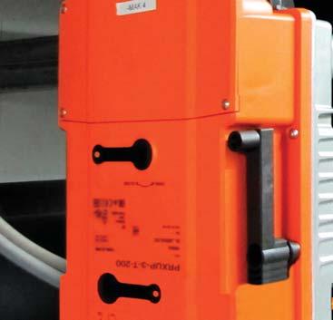
23 Installation L Series Butterfly Valves Auxiliary Switch Setup for PR and PKR Actuators The setting of the auxiliary switches work like the S2A module. The first auxiliary switch is fixed at 10, the second auxiliary switch can be set between 0 and 90. A YouTube video is available to further help explain the auxiliary switch settings. o p e n A 10 S1 S2 S3 S5 S6 S5 S6 S4 S4 3 S5 S6 S4 S2 S3 S5 S6 S4 1 Remove power 2 Gear disengagement Opening the manual override cover and adjust the hand crank. 2 o p e n 3 Manual override control Turn the hand crank until the desired switched position A is indicated and then remove the crank. 1 4 Auxiliary switch Opening the auxiliary switch adjustment cover and adjust the hand crank. Turn the crank until the arrow points to the vertical line. S1 S2 S3 S4 S5 S6 4 5 Terminals Connect continuity tester to S4 + S5 or S4 + S6. If the auxiliary switch should switch in the opposite direction, rotate the hand crank 180º. Manual Override Function for PR and PKR Actuator The PR actuator offers a hand crank connection. When the hand crank is placed correctly then the actuator is disengaged. 23
 (linear 5.")
24 Installation L Series Butterfly Valves Sensor Monitoring with MFT Models of PR and PKR Actuators The PR actuator with BACnet interface and the PKR electronic fail-safe actuator offer 2 passive sensor inputs. PT1000 NI1000 NTC10k Typ2 B3970 (linear 3.89Ohm/ C) (linear 5.7Ohm/ C) Without sensor failure Without sensor failure Without sensor failure Ohm [ ] failure = 3% Ohm [ ] failure = 3% Ohm [ ] failure = 7% ±10 accuracy ±10 accuracy ±3 accuracy Sequence of the LED lights: Green LED status indicator light sequence: On: operation ok, no faults Blinking: fail-safe mechanism is active Off: fault is detected or not in operation/capacitors charging Charge and bridge time of the PKR: The initial charge time is 20 seconds with a settable delay or bridge time of 0-10 seconds for brown out interruptions. WARNING: The wiring technician must be trained and experienced with electronic circuits. Disconnect power supply before attempting any wiring connections or changes. Make all connections in accordance with wiring diagrams and follow all applicable local and national codes. Provide disconnect and overload protection as required. Use copper, twisted pair, conductors only. If using electrical conduit, the attachment to the actuator must be made with fl exible conduit. 24
25 Commissioning with Near Field Communication (NFC) The PR actuator with Near Field Communication (NFC) allows for easy commissioning, programming and troubleshooting directly from your smartphone, even when the actuator is not powered. Settings can also be changed with the ZTH-US handheld tool. The following table shows the factory settings and settings that can be changed with NFC and ZTH-US. Values & Settings Factory Setting Manual Power On Power Off Power On Running time setting [ s] 35 s - RW RW RW Max angle of rotation 100% - RW RW RW Actuator Position [0-100%] - Position Indicator R - R Setting for auxiliary switch s2 [0-90 ] 85% Hand crank Display of input signal voltage (Power supply) - - R - - Valve Setting [Regular, 8, 10, 12 ] Type specifi c - RW RW - Override Control (Force Position) - Hand crank RW - RW Location String - - RW RW - Control [Floating Point, On/Off, V, 2-10V, 4-20 ma] 2..10V - RW RW RW Feedback Mode [2-10V, V, inverted] 2..10V - RW RW RW Feedback Mode [DC variable] RW Control Signal [DC variable] RW Control Signal Fail Position [None, On/Off] None - RW RW - Hybrid Mode - Setpoint [MP-Bus, Analog] Bus - RW RW - Bus Setting [MP-Bus, BACnet] MP, PP - RW RW - Power Off Position [0-100%] 0% RW RW RW Power Fail Delay [0-10 s] 2 s RW RW RW [R=reading; W=writing] 25
26 Protocol Implementation Conformance Statement (PICS) General information Date: 3. April 2017 Vendor Name: BELIMO Automation AG Vendor ID: 423 Product Name: Product Model Number: Applications Software Version: Firmware Revision: BACnet Protocol Revision: 1.12 Product Description: Actuator for butterfly valves providing two sensor inputs BACnet Standard Device Profile: Rotary actuator for butterfly valves BACMFT for xy, e.g. PRBUP-MFT-T, PKRBUP-MFT-T BACnet Application Specific Controller (B-ASC) BACnet Interoperability Building Blocks supported: Data Sharing - ReadProperty-B (DS-RP-B) Data Sharing - ReadPropertyMultiple-B (DS-RPM-B) Data Sharing - WriteProperty-B (DS-WP-B) Data Sharing - Write Property Multiple-B (DS-WPM-B) Data Sharing - COV-B (DS-COV-B) Device Management - DynamicDeviceBinding-B (DM-DDB-B) Device Management - DynamicObjectBinding-B (DM-DOB-B) Device Management - DeviceCommunicationControl-B (DM-DCC-B) Segmentation Capability: Data Link Layer Options: Device Address Binding: Networking Options: Character Sets Supported: Gateway Options: Network Security Options: No MS/TP master, baud rates: 9'600, 19'200, 38'400, 76'800, 115'200 No static device binding supported None ISO (UTF-8) None Non-secure Device 26
27 Protocol Implementation Conformance Statement (PICS) PICS (continued) Standard objects The device provides datapoints for common operation as well as datapoints for parameterization. Datapoint BACnet Object Relative Setpoint in % AO [1] Override Control MO [1] Relative Position in % AI [1] Absolute Position in AI [2] Analog Setpoint in % AI [6] Sensor 1 Type MV [220] Sensor 1 as analog value AI [20] Sensor 2 Type MV [221] Sensor 2 as analog value AI [21] Summary Status BI [101] Command: Initiate Function MV [120] Max Setpoint in % AV [98] Bus Watchdog in s AV [130] Object processing Object type Optional properties Writeable properties Service processing Analog Input Analog Output Description COV_Increment Description COV_Increment COV_Increment COV_Increment Present_Value Relinquish_Default Analog Value Description Present_Value Binary Input Description Active_Text Inactive_Text Device Description Object_Identifier Location Object_Name (max. 32 char) Active_COV_Subscription Location (max. 64 char) Description (max. 64 char) APDU_Timeout Number_Of_APDU_Retries Max_Master Max_Info_Frames Multi-state Output Description Present_Value State_Text Relinquish_Default Multi-state Value Description Present_Value State_Text The device does not support the CreateObject and DeleteObject service. The specified maximum length of writable strings is based on single-byte characters. No support of COV subscription on Analog Value objects. The device supports DeviceCommunicationControl service. No password is required. Max. 6 active COV subscriptions with lifetime up to 8 h supported 27
28 BACnet Object Description Object Name Object Type / Instance Description Values Default Device_Name Device [x] SpRel Analog Output [1] Relative Setpoint in % If analog control is enabled, the Present_Value is not evaluated and Out_of_Service is TRUE and. Override Multi-state Output[1] Override Control Override control is possible in analog or digital control. Min/Mid are not supported by the device and interpreted as 0% RelPos Analog Input [1] Relative Position in % None Open Close Min Mid Max None - If the gear is disengaged, it is signaled in the Status_Flags:OVERRIDDEN=TRUE. AbsPos Analog Input [2] Absolute Position in If the gear is disengaged, it is signaled in the Status_Flags:OVERRIDDEN=TRUE. SpAnalog Analog Input [6] Analog Setpoint in % , 0-100, 110% - The Present_Value represents the relative value calculated from the analog signal (3- point, 0-10 V, 4-20 ma). If analog control is disabled, the Present_Value is not updated and Out_of_Service is TRUE and. Sens1Type Multi-state Value [220] Sensor 1 Type The sensor input T1 supports passive temperature sensors only. The measured signal is provided by Sens1Analog either as resistance value (Passive 1K, Passive 20K) or as converted temperature (PT1000, NI1000, NTC10K) in C or F. None - Passive_1K Passive_20K - PT1000_C NI1000_C NTC10K_C PT1000_F NI1000_F NTC10K_F Ω C Sens1Analog Analog Input [20] Sensor 1 as analog value in Ω or C/ F k F Sens2Type Multi-state Value [221] Sensor 2 Type, according Sens1Type None Sens2Analog Analog Input [21] Sens1Analog, according Sens1Analog - SummaryStatus Binary Input [101] Summary Status None Fault - Command Multi-state Value [120] Initiate Function None - Test Reset - MaxSp Analog Value [98] Max setpoint in % BusWatchdog Analog Value [130] Timeout for Bus Watchdog in s None - 0s = watchdog deactivated If neither the Present_Value for AO[1] nor MV[1] is updated within the period, the Priority_Array of both objects is cleared and the Relinquish_Default becomes valid. 28

29 Retrofit PR actuators can be used for retrofi tting competitor butterfl y valves that require under 1400 in-lbs. Until released, contact Technical Support for a custom linkage. 1, 2, and 3 are required to retrofi t. Refer below for required parts for custom retrofi t. PR Actuators 1 IND-PR04 2 Linkage Kit UFSP0020 or UFSP Valve Size Valve Series 2-way Valve Linkage with Position Indicator 2-way Valve Linkage without Position Indicator 3-way Valve Linkage without Position Indicator 4-6 HD IND-PR01 IND-PR02 UFLK HD Not Available - Use SY Series* Not Available - Use SY Series* Not Available - Use SY Series* 8, 10, 12 L IND-PR03 IND-PR04 UFLK , 12 HD Not Available - Use SY Series* Not Available - Use SY Series* Not Available - Use SY Series* * Contact Technical Support for details. 29
30 PR, PKR Replacement of SY On/Off Actuator In case an SY3 on/off is replaced with a PR actuator, the following changes are needed. The SY is a 3-wire device and the PR actuator is a 4-wire device and additional wiring changes to the auxiliary switches are required. See below. Ground power and control signal wiring revisions. Replace an SY series on/off control actuator with a PR, PKR series actuator with noted R1, R2 revisions. See table 1 for terminal cross reference WARNING: The wiring technician must be trained and experienced with electronic circuits. Disconnect power supply before attempting any wiring connections or changes. Make all connections in accordance with wiring diagrams and follow all applicable local and national codes. Provide disconnect and overload protection as required. Use copper, twisted pair, conductors only. If using electrical conduit, the attachment to the actuator must be made with fl exible conduit. 30
31 Auxiliary Switch Wiring Modifications for PR Replacement of SY Actuators Refer to table 2 for terminal cross reference. When travel setpoint is achieved the SPDT normally open (NO) contact becomes closed. For example; when the original SY actuator travel is 85 the A-C contact is closed. When PR, PKR actuator travel is 85 (default) the S4-S6 contact is closed. A B C D E F NC NO NC NO LS3 85 LS4 5 Auxiliary Switch Wiring Cross Reference Series SY PR/PKR SPDT (Normal) Terminal Com A S4 NC B S5 NO C S6 Com D S1 NC E S3 NO F S2 SY Series (original) See submittal document for details PR, PKR Series (replacement) See submittal document for details Table 2 WARNING: The wiring technician must be trained and experienced with electronic circuits. Disconnect power supply before attempting any wiring connections or changes. Make all connections in accordance with wiring diagrams and follow all applicable local and national codes. Provide disconnect and overload protection as required. Use copper, twisted pair, conductors only. If using electrical conduit, the attachment to the actuator must be made with fl exible conduit. 31
![Valve Accessories PROGRAMMING TOOLS INTERFACES, CABLES MFT-P Belimo MFT configuration software (V3.X), includes PC-Tool software (interface cables [ZTH US] not included). Physical copy of software.](/docs-images/88/115314798/images/32-0.jpg "Free download also available at www.belimo.us/americas/mft.html Near Field Communication (NFC) App Allows fast programming, commissioning, and troubleshooting even when the actuator is not powered.")
32 Valve Accessories PROGRAMMING TOOLS INTERFACES, CABLES MFT-P Belimo MFT configuration software (V3.X), includes PC-Tool software (interface cables [ZTH US] not included). Physical copy of software. Free download also available at Near Field Communication (NFC) App Allows fast programming, commissioning, and troubleshooting even when the actuator is not powered. Available through Google Play ZTH US Handheld interface module that allows fi eld programming. Includes ZK1-GEN, ZK2-GEN, and ZK6-GEN cables ZK1-GEN Cable for use with ZTH US to connect to new generation non-spring return actuator via diagnostic/programming socket ZK2-GEN Cable for use with ZTH US to connect with spring return and non-spring return actuators not equipped with diagnostic/ programming socket ZK6-GEN Cable for use with ZTH US to connect to SY actuator via RJII port ZTH-BT-NFC Bluetooth to NFC converter for temporary wireless operation of Belimo devices with an NFC interface. AM/ AR NON-SPRING RETURN GM/ GR ELECTRONIC FAIL-SAFE SPRING RETURN DR PR SY DK PKR GK AF Available on NFC Labeled Actuators Only NON-SPRING RETURN BATTERY BACKUP AM/AR GM/GR/DR SY NOTE: Each NSV24 US requires 2 NSV-BAT. *All EXT part numbers are not returnable. NSV24 US Battery backup module NSV-BAT 12VDC 1.2 AH battery (2 required) EXT-NSV-B03-120* Battery backup system, SY4 - SY6 120 VAC, on/off actuators EXT-NSV-B04-120* Battery backup system, SY4 - SY6 120 VAC, MFT actuators EXT-NSV-B05-120* Battery backup system, SY7 - SY VAC, on/off actuators EXT-NSV-B06-120* Battery backup system, SY7 - SY VAC, MFT actuators EXT-NSV-B13-24* Battery backup system, SY4 - SY5 24 VAC, on/off actuators EXT-NSV-B14-24* Battery backup system, SY4 - SY5 24 VAC, MFT actuators EXT-NSV-B23-230* Battery backup system, SY4 - SY6 230 VAC, on/off actuators EXT-NSV-B24-230* Battery backup system, SY4 - SY6 230 VAC, MFT actuators EXT-NSV-B25-230* Battery backup system, SY7 - SY VAC, on/off actuators EXT-NSV-B26-230* Battery backup system, SY7 - SY VAC, MFT actuators 32

33 Valve Accessories NON-SPRING RETURN ACTUATORS ELECTRONIC FAIL-SAFE SPRING RETURN ACTUATORS WEATHER SHIELDS AM GM/GR DR SY DK/DKR AF *Cannot be used with direct mount actuators. ELECTRIC DISCONNECT ZS-BFV-20* For GM, GK actuators on F6, F7, HD ZS-BFV-30* For AF actuators on F6, F7, HD ZS-BFV-60* For dual GM, GK actuators on F6 HD ZS-BFV-70* For dual AF series on F6 HD ZS-BFV-80* For dual AF series on F6 HD ZS-BFV-90* Dual AF, GM, GK series for F7 HD Local electric disconnect for SY2-SY12 110/230V - 2 position HOA-120VMFT Local electric disconnect for SY2-SY12 110/230V - modulating HOA-24V Local electric disconnect for SY2-SY12 24V - 2 position HOA-24VMFT Local electric disconnect for SY2-SY12 24V - modulating AUXILIARY SWITCHES & POTENTIOMETERS SY-1000-FB01 Feedback potentiometer 1000, 2 position, factory installed option only SY-1000-FB02 Feedback potentiometer 1000, modulating (models Syx -P, -SR or MFT), factory installed option only S1A Auxiliary switch 1x SPDT, 3A (0.5A 250 VAC S2A Auxiliary switch 2x SPDT, 3A (0.5A 250 VAC P140A GR Feedback potentiometer 140 P500A GR Feedback potentiometer 500 P1000A GR Feedback potentiometer 1000 P2800A GR Feedback potentiometer 2800 P5000A GR Feedback potentiometer 5000 P10000A GR Feedback potentiometer HOUSING ZS-T Terminal cover for NEMA 2 (-T models) HAND CRANK PR PKR ZG-HND PR Replacement hand crank for PR and PKR actuators 33
34 Valve Accessories VALVE MANUAL HANDLES HD L GEAR OPERATORS F650HD+HND01 2 HD series valve with manual handle ductile iron, 200 psi close-off, C v 115 F665HD+HND01 2½ HD series valve with manual handle ductile iron, 200 psi close-off, C v 196 F680HD+HND01 3 HD series valve with manual handle ductile iron, 200 psi close-off, C v 302 F6100HD+HND02 4 HD series valve with manual handle ductile iron, 200 psi close-off, C v 600 F6125HD+HND02 5 HD series valve with manual handle ductile iron, 200 psi close-off, C v 1022 F6150HD+HND02 6 HD series valve with manual handle ductile iron, 200 psi close-off, C v 1579 F650HD+GW01 2 HD series valve with manual gear operator ductile iron, 200 psi close-off, C v 115 F665HD+GW01 2½ HD series valve with manual gear operator ductile iron, 200 psi close-off, C v 196 F680HD+GW01 3 HD series valve with manual gear operator ductile iron, 200 psi close-off, C v 302 F6100HD+GW02 4 HD series valve with manual gear operator ductile iron, 200 psi close-off, C v 600 F6125HD+GW02 5 HD series valve with manual gear operator ductile iron, 200 psi close-off, C v 1022 F6150HD+GW02 6 HD series valve with manual gear operator ductile iron, 200 psi close-off, C v 1579 F6200L+ZD6N-S150 8 L series valve with manual gear operator ductile iron, 200 psi close-off, C v 3136 F6250L+ZD6N-S L series valve with manual gear operator ductile iron, 200 psi close-off, C v 5340 F6300L+ZD6N-S L series valve with manual gear operator ductile iron, 200 psi close-off, C v 5340 F6350HD+GW04 14 HD series valve with manual gear operator ductile iron, 150 psi close-off, C v F6400HD+GW05 16 HD series valve with manual gear operator ductile iron, 150 psi close-off, C v F6450HD+GW06 18 HD series valve with manual gear operator ductile iron, 150 psi close-off, C v F6500HD+GW07 20 HD series valve with manual gear operator ductile iron, 150 psi close-off, C v


35 Frequently Asked Questions (FAQ) Does the PR actuator make an adaptation during the first commissioning? The PR actuator comes with an integrated potentiometer, therefore an adaptation is not necessary. The actuator always knows its position. Is it allowed to mount the PR actuator upside down? Yes, for indoor applications only. Can the new 8 and 12 butterfly valves also be used for dead-end service? The new butterfl y valves can only be used with a closed counter-fl ange for dead-end service. Can the new butterfly valves also be used for district heating and cooling applications or for ANSI 250/300 applications? The new butterfl y valves are not suitable for these applications, due to longer pipes and the high pressure drops associated with them. These valves are ANSI 125/150 type fl anges. Can we motorize an existing F6200HD butterfly valve with a PR actuator? The PR actuator is NOT available for the F6200HD butterfl y valve. The reason is that the SY3 actuator has a nominal torque of 150 Nm but can shortly develop a higher torque. The PR actuator has a constant 160 Nm torque. If a replacement for a SY3 is needed, the SY3 is still available until end of 2018 and afterwards a SY4 can be delivered as a replacement. Is it possible for a butterfly valve to be installed in the line without an actuator? Yes, but not for long periods of time. The butterfl y valve may not be operated without an actuator or gear operator if there is fl ow in the line. In the absence of an actuator or gear operator, the butterfl y valve might close and cause damage (water hammer). Why is there no possibility to use the PC-Tool for parameterization? The future tool for parameterization is the Belimo Assistant App. In a long term perspective the PC-Tool will not be supported. 35
Butterfly Valves (BFV)
") Butterfly Valves (BFV) O904-02/12 - Subject to change. Belimo Aircontrols (USA), Inc. Application A comprehensive line of Butterfl y Valves is available in sizes ranging from 2 to 30 in both standard and
Butterfly Valves (BFV) O904-02/12 - Subject to change. Belimo Aircontrols (USA), Inc. Application A comprehensive line of Butterfl y Valves is available in sizes ranging from 2 to 30 in both standard and
PRESSURE INDEPENDENT CONTROL VALVES (epiv & PICCV )
") 7 PRESSURE INDEPENDENT CONTROL VALVES (epiv & PICCV ) Pressure independent valves compensate for pressure variations, performing a continual balancing function to maintain system performance at varying
7 PRESSURE INDEPENDENT CONTROL VALVES (epiv & PICCV ) Pressure independent valves compensate for pressure variations, performing a continual balancing function to maintain system performance at varying
PRESSURE INDEPENDENT CONTROL VALVES (PICCV& epiv)
") 7 PRESSURE INDEPENDENT CONTROL VALVES (& epiv) Pressure independent valves compensate for pressure variations, performing a continual balancing function to maintain system performance at varying loads.
7 PRESSURE INDEPENDENT CONTROL VALVES (& epiv) Pressure independent valves compensate for pressure variations, performing a continual balancing function to maintain system performance at varying loads.
Butterfly Valve Retrofits
 Butterfly Valve Retrofits Contents How to Select the Butterfly Retrofit Solution... pg 127 Butterfly Valve Retrofit Actuators... pg 128 Solutions for Specific Manufacturer and Part Number Apollo... pg
Butterfly Valve Retrofits
 Butterfly Valve Retrofits Contents How to Select the Butterfly Retrofit Solution... pg 127 Butterfly Valve Retrofit Actuators... pg 128 Solutions for Specific Manufacturer and Part Number Apollo... pg
F6200L, 8, 2-Way Butterfly Valve Resilient Seat, 304 Stainless Steel Disc
 F6200, 8, 2-Way Butterfly Valve Resilient Seat, 304 Stainless Steel Disc Application Valve is designed f use in ASI flanged piping systems to meet the needs of bi-directional high flow HVAC hydronic applications
Installation Instructions
 Quick-Mount Visual Instructions for Mechanical Installation Quick-Mount Visual Instructions 1. Rotate the damper to its failsafe position. If the shaft rotates counterclockwise, mount the CCW side of the
Butterfly Valve Retrofits
 Butterfly Valve Retrofits Contents How to Select the Butterfly Retrofit Solution... pg 127 Butterfly Valve Retrofit Actuators... pg 128 Solutions for Specific Manufacturer and Part Number Apollo... pg
F6250L, 10, 2-Way Butterfly Valve Resilient Seat, 304 Stainless Steel Disc
 F6250, 10, 2-Way Butterfly Valve Resilient Seat, 304 Stainless Steel Disc Application Valve is designed f use in ASI flanged piping systems to meet the needs of bi-directional high flow HVAC hydronic applications
Installation Instructions
 Quick-Mount Visual Instructions for Quick-Mount Visual Instructions 1. Rotate the damper to its failsafe position. If the shaft rotates counterclockwise, mount the CCW side of the actuator out. If it rotates
F6150HD, 6, 2-Way Butterfly Valve Resilient Seat, 304 Stainless Steel Disc
 F6150HD, 6, 2-Way Butterfly Valve Resilient Seat, 304 Stainless Steel Disc Application Valve is designed f use in ASI flanged piping systems to meet the needs of bi-directional high flow HVAC hydronic
F6300L, 12, 2-Way Butterfly Valve Resilient Seat, 304 Stainless Steel Disc
 F6300, 12, 2-Way Butterfly Valve Resilient Seat, 304 Stainless Steel Disc Application Valve is designed f use in ASI flanged piping systems to meet the needs of bi-directional high flow HVAC hydronic applications
F6150HD, 6, 2-Way Butterfly Valve Resilient Seat, 304 Stainless Steel Disc
 F6150HD, 6, 2-Way Butterfly Valve Resilient Seat, 304 Stainless Steel Disc Application Valve is designed f use in ASI flanged piping systems to meet the needs of bi-directional high flow HVAC hydronic
pressure independent characterized control tm
 5 pressure independent characterized control tm valves (PICCV ) PICCV reacts to pressure variations, performing a continual balancing function to maintain system performance at varying loads. Wide range
BELIMO CONTROLS
 INDEX ACCESSORIES MECHANICAL CRANK ARM ADAPTOR KITS... 7-17 JACKSHAFT LINKAGE FOR SPRING RETURN DAMPER ACTUATORS... 7-17 MISCELLANEOUS... 7-17 MOUNTING BRACKETS... 7-17 DAMPER ACTUATORS FIRE AND SMOKE
Technical Documentation Pressure Independent Characterized Control Valves (PICCV) Patented Effective December 2007
 Patented Effective December 2007") Technical Documentation Pressure Independent Characterized Control Valves (PICCV) Patented Effective December 2007 Belimo Project: 1100 Peachtree, Atlanta, Georgia Control Valve Product Range Electronic
Technical Documentation Pressure Independent Characterized Control Valves (PICCV) Patented Effective December 2007 Belimo Project: 1100 Peachtree, Atlanta, Georgia Control Valve Product Range Electronic
Installation Instructions
 Quick-Mount Visual Instructions for Mechanical Installation Quick-Mount Visual Instructions. Rotate the damper to its failsafe position. If the shaft rotates counterclockwise, mount the CCW side of the
B2/B3 Series Characterized Control Valve, Non-Spring Return Actuator
 /3 Series Characterized Control Valve, Non-Spring ctuator Two-way and Three-way Valves with Chrome Plated rass all and rass Stem, NPT Female Ends Service: Flow characteristic: Media Temp Range: mbient
B2 Series Characterized Control Valve, Non-Spring Return Actuator
 2 Series Characterized Control Valve, Non-Spring ctuator Two-way Valve with Stainless Steel all and Stem, NPT Female Ends Service: Flow Characteristic: Media Temp Range: Maximum Differential: Pressure
Electronic Pressure Independent Valves (epiv)
") Electronic Pressure Independent Valves (epiv) Features / Benefits Electronic Pressure Independent Valves (epiv) Valve Innovations Pressure independent valves compensate for pressure variations, performing
Electronic Pressure Independent Valves (epiv) Features / Benefits Electronic Pressure Independent Valves (epiv) Valve Innovations Pressure independent valves compensate for pressure variations, performing
LF24-SR US TF24-SR US TFX24 US LF24 US. B3 B Three-way Characterized Control Valve, Chrome Plated Brass Ball and Brass Stem
 / Series Characterized Control Valve, Spring ctuator Two-way and Three-way Valves with Chrome Plated rass all and rass Stem, NPT Female Ends Service: Flow Characteristic: Media Temp Range: mbient Temp
The Belimo Butterfly Valves
 The Belimo Butterfly Valves Belimo D(U)6..series Butterfly Valves are designed to meet the stringent needs of HVAC applications requiring positive shutoff for liquids. Valve design features 2 1 7 To satisfy
Pressure Independent Characterized Control Valves (PICCV)
") 700-0000H INSTALLATION INSTRUCTIONS Pressure Independent Characterized Control Valves (PICCV) Features Actuator can be mounted in four different positions Perpendicular mounting fl ange and square drive
700-0000H INSTALLATION INSTRUCTIONS Pressure Independent Characterized Control Valves (PICCV) Features Actuator can be mounted in four different positions Perpendicular mounting fl ange and square drive
Mount directly to 1.05 jackshafts. (new ZG-120 bracket shown) EFB24-S N4, EFX24-S N4(H) EFB24-S, EFX24-S (p. 21)
 EFB24-S N4, EFX24-S N4(H) EFB24-S, EFX24-S (p. 21)") EFB and EFX Series Spring Return Direct Coupled Actuator Minimum 70 in-lb Torque For damper areas up to 66 sq-ft* (For lower torque, see AFB, AF, NFB, LF, or TF series) Applications New standard clamp
EFB and EFX Series Spring Return Direct Coupled Actuator Minimum 70 in-lb Torque For damper areas up to 66 sq-ft* (For lower torque, see AFB, AF, NFB, LF, or TF series) Applications New standard clamp
Globe Valve Retrofits
 Globe Retrofits Contents How to Select the Globe Retrofit Solution... pg 33 Globe Retrofit Actuators... pg 34 Solutions for Specific Manufacturer and Part Number Honeywell... pg 37 Johnson Controls...
Z2 050 Q -J +CQB 24 -SR -L
 ZoneTight Zone Valve () (½ to ¾ ) Nomenclature Z2 050 Q -J +CQB 24 -SR -L Valve Type Z2 = 2-way Z3 = 3-way ZoneTight Chrome Plated Brass Ball and Brass Stem Valve Size 050 = ½ 075 = ¾ Quick Connect E =
Globe Valve Retrofits
 Globe Valve Retrofits Contents How to Select the Globe Valve Retrofit Solution... pg 33 Globe Valve Retrofit Actuators... pg 34 Solutions for Specific Manufacturer and Part Number Honeywell... pg 37 Johnson
FlowCon SM mm. Dynamic Self Balancing Control Valve SPECIFICATIONS
 FlowCon SM 50-150mm Dynamic Self Balancing Control Valve SPECIFICATIONS Pressure rating: 4000 kpa / 580 psi Temperature rating, media: -20 C to +120 C / -4 F to +248 F Temperature rating, ambient: -10
High temperature characterized control valves
 9 High temperature characterized control valves (HTCCV) Extremely low lead content enabling valve to be used as a potable water valve. Fluid dynamically designed characterizing elongated disc reduces turbulent
Pressure Independent Characterized Control Valves (PICCV)
") Features / Benefits Pressure Independent Characterized Control Valves (PICCV) Pressure Independent Characterized Control Valves (PICCV) Thermal isolating adapter between fl ange and actuator Vent holes
Features / Benefits Pressure Independent Characterized Control Valves (PICCV) Pressure Independent Characterized Control Valves (PICCV) Thermal isolating adapter between fl ange and actuator Vent holes
P2050S-030, 1/2, Electronic Pressure Independent Valve Stainless Steel Ball and Stem, Female NPT Ends
 P2050S-030, 1/2, Electronic Pressure Independent Valve Stainless Steel Ball and Stem, Female NPT Ends Application Water-side control of heating and cooling systems for AHUs and water coils. Equal Percentage/
Globe Valve Retrofits
 Globe Valve Retrofits Contents How to Select the Globe Valve Retrofit Solution... pg 33 Globe Valve Retrofit Actuators... pg 34 Solutions for Specific Manufacturer and Part Number Honeywell... pg 37 Johnson
Electronic Pressure Independent Valves (epiv)
") Version 08.21.17 Electronic Pressure Independent Valves (epiv) Features / Benefits Electronic Pressure Independent Valves (epiv) Valve Innovations Pressure independent valves compensate for pressure variations,
Version 08.21.17 Electronic Pressure Independent Valves (epiv) Features / Benefits Electronic Pressure Independent Valves (epiv) Valve Innovations Pressure independent valves compensate for pressure variations,
2006 Product Range Overview. Belimo Project: One Bellevue Center, Seattle, Washington
 2006 Product Range Overview Belimo Project: One Bellevue Center, Seattle, Washington Actuator Product Range Spring Return TF 18 in-lb [2 Nm] Approx. 4.5 sq. ft. LF 35 in-lb [4 Nm] Approx. 8 sq. ft. NF
NMB (X) 24-MFT. Proportional Control, Non-Spring Return, Direct Coupled, 24V, Multi-Function Technology
 24-MFT. Proportional Control, Non-Spring Return, Direct Coupled, 24V, Multi-Function Technology") NMB (X) -MFT Proportional Control, Non-Spring Return, Direct Coupled, V, Multi-Function Technology Torque min. 90 in-lb for control of damper surfaces up to sq ft. Technical Data NMB(X)-MFT Power Supply
NMB (X) -MFT Proportional Control, Non-Spring Return, Direct Coupled, V, Multi-Function Technology Torque min. 90 in-lb for control of damper surfaces up to sq ft. Technical Data NMB(X)-MFT Power Supply
G3 (D) 3-way Globe Valve, Bronze Trim
 3-way Globe Valve, Bronze Trim") G3 (D) 3-way Globe Valve, Bronze Trim pplication This valve is typically used in ir Handling Units on heating or cooling coils and Fan Coil Unit heating or cooling coils. Some other common applications
G3 (D) 3-way Globe Valve, Bronze Trim pplication This valve is typically used in ir Handling Units on heating or cooling coils and Fan Coil Unit heating or cooling coils. Some other common applications
NV Direct Coupled Globe Valve Actuator
 70396 Rev. C Non-spring return, on/off, floating point, proportional control NV Direct Coupled Globe Valve Actuator NV24-3 US NVD24-3 US NV24-MFT US NVD24-MFT US Application For on/off, floating point
Valve Accessories Butterfly Valves
 PROGRAMMING TOOLS INTERFACES, CABLES MFT-P Belimo MFT configuration software (V3.X) Includes: PC-Tool software (interface cables [ZTH US] not included) NFC App Near Field Communication (NFC) App allows
Advanced butterfly valves provide energy savings and optimal performance in Kuhn Champignon s mushroom plant facility Product Range Overview
 Advanced butterfly valves provide energy savings and optimal performance in Kuhn Champignon s mushroom plant facility. 2017 Product Range Overview Effective April 1, 2017 Innovations in Comfort, Energy
Installation, Operation and Maintenance Manual
 Document Number 478799 AMD-xx-TD Series Installation, Operation and Maintenance Manual Please read and save these instructions for future reference. Read carefully before attempting to assemble, install,
LMB24-3 (-S)(-T) On/Off-Floating Point Control, Non-Spring Return, Direct Coupled, 24 V
(-T) On/Off-Floating Point Control, Non-Spring Return, Direct Coupled, 24 V") LMB- (-S)(-T) On/Off-Floating Point Control, Non-Spring Return, Direct Coupled, V Torque min. 5 in-lb for control of damper surfaces up to sq ft. Technical Data LMB- on/off-floating Power Supply VAC ±
LMB- (-S)(-T) On/Off-Floating Point Control, Non-Spring Return, Direct Coupled, V Torque min. 5 in-lb for control of damper surfaces up to sq ft. Technical Data LMB- on/off-floating Power Supply VAC ±
NFB24, NFB24-S, NFX24, NFX24-S On/Off, Spring Return, 24 V
 NFB4, NFB4-S, NFX4, NFX4-S On/Off, Spring Return, 4 V Torque min. 90 in-lb, for control of air dampers Technical Data Power supply Power consumption Transformer sizing Electrical connection NFB4... NFX4...
Minimum 27 in-lb Torque
 LU Series Actuator Minimum 27 in-lb Torque For damper areas up to 6.8 sq-ft* Actuators in bold have BDCM LU Series - At A Glance LUB(X)24-3 (p. 351) LUX120-3 (p. 353) LUB(X)24-SR (p. 355) LUX120-SR (p.
AMB24-3(-S) On/Off-Floating Point Control, Non-Spring Return, Direct Coupled, 24 V
 On/Off-Floating Point Control, Non-Spring Return, Direct Coupled, 24 V") AMB4-3(-S) On/Off-Floating Point Control, Non-Spring Return, Direct Coupled, 4 V Torque min. 80 in-lb for control of damper surfaces up to 45 sq ft. Application For on/off and floating point control of
AMB4-3(-S) On/Off-Floating Point Control, Non-Spring Return, Direct Coupled, 4 V Torque min. 80 in-lb for control of damper surfaces up to 45 sq ft. Application For on/off and floating point control of
Torque min. 35 in-lb, for control of air dampers
 LF-SR (-S) US Proportional Damper Actuator, Spring Return Fail-Safe, V for to VDC, or to ma Control Signal. Output Signal of to VDC for Position Indication. Torque min. 35 in-lb, for control of air dampers
LMX120-SR. Proportional Control, Non-Spring Return, Direct Coupled,100 to 240 VAC, for 2 to 10 VDC and 4 to 20 ma
 LMX0-SR Proportional Control, Non-Spring Return, Direct Coupled,00 to 0 VAC, for to 0 VDC and to 0 ma Torque min. 5 in-lb for control of damper surfaces up to sq ft. Application For proportional modulation
Minimum 90 in-lb Torque. Applications. NFB, NFX Series At A Glance. NFB and NFX Series Spring Return Direct Coupled Actuator
 NFB and NFX Series Spring Return Direct Coupled Actuator Minimum 90 in-lb Torque For damper areas up to sq-ft* Applications 1 3/4 1/ New standard clamp fits standard 1/ shafts to 1.05 jackshafts. Mount
Installation, Operation and Maintenance Guide II NIBCO High Performance Butterfly Valves Series 6822 and 7822
 Installation, Operation and Maintenance Guide II NIBCO High Performance Butterfly Valves Series 6822 and 7822 Statements: NIBCO High Performance Butterfly Valves, Series 6822 and 7822, have been designed
Electronic Pressure Independent Valve (epiv)
") 71167-00001.B INSTALLATION INSTRUCTIONS Electronic Pressure Independent Valve (epiv) epiv with Non-Spring Rt Return and Electronic Fail-Safe Actuators AR, GR, AKR, GKR Series Installation Instructions
71167-00001.B INSTALLATION INSTRUCTIONS Electronic Pressure Independent Valve (epiv) epiv with Non-Spring Rt Return and Electronic Fail-Safe Actuators AR, GR, AKR, GKR Series Installation Instructions
Versatile and Powerful
 AM Series Direct Coupled Actuator Versatile and Powerful Minimum 180 in-lb torque in a compact package. For damper areas up to 45 sq-ft* All Actuators have BDCM AM Series - At A Glance AMB(X)24-3 (p. 148)
AMB24-3(-S) On/Off-Floating Point Control, Non-Spring Return, Direct Coupled, 24 V
 On/Off-Floating Point Control, Non-Spring Return, Direct Coupled, 24 V") AMB-(-S) On/Off-Floating Point Control, Non-Spring Return, Direct Coupled, V Torque min. 80 in-lb for control of damper surfaces up to 5 sq ft. Application For on/off and floating point control of dampers
AMB-(-S) On/Off-Floating Point Control, Non-Spring Return, Direct Coupled, V Torque min. 80 in-lb for control of damper surfaces up to 5 sq ft. Application For on/off and floating point control of dampers
CENTER LINE. INSTALLATION and MAINTENANCE INSTRUCTIONS RESILIENT SEAT BUTTERFLY VALVES MANUAL AND AUTOMATED
 INSTALLATION and MAINTENANCE INSTRUCTIONS MANUAL AND AUTOMATED RESILIENT SEAT BUTTERFLY VALVES CONTENTS Introduction Valve Description... Valve Design Features... Flange and Pipe Schedule Compatibility...
LMCB24-SR LMCB24-SR-T. applications. Dimensions (All numbers in brackets are in millimeters.) 1/4 to 3/4 [6 to 20] 5/16 to 3/4 [8 to 26] 1.
![LMCB24-SR LMCB24-SR-T. applications. Dimensions (All numbers in brackets are in millimeters.) 1/4 to 3/4 [6 to 20] 5/16 to 3/4 [8 to 26] 1.](/thumbs/95/124319282.jpg "LMCB24-SR LMCB24-SR-T. applications. Dimensions (All numbers in brackets are in millimeters.) 1/4 to 3/4 [6 to 20] 5/16 to 3/4 [8 to 26] 1.") LMCB4-SR (-T) Proportional Control, Non-Spring Return, Direct Coupled, 4V, for to 0 VDC and 4 to 0 ma Torque min. 45 in-lb for control of damper surfaces up to sq ft. LMCB4-SR LMCB4-SR-T HALOMO Brushless
LMCB4-SR (-T) Proportional Control, Non-Spring Return, Direct Coupled, 4V, for to 0 VDC and 4 to 0 ma Torque min. 45 in-lb for control of damper surfaces up to sq ft. LMCB4-SR LMCB4-SR-T HALOMO Brushless
Minimum 27 in-lb torque
 LU Series Actuator Minimum 27 in-lb torque For damper areas up to 6.8 sq-ft* All Actuators have BDCM LU Series - At A Glance LUB(X)24-3 (p. 258) LUB(X)24-SR (p. 260) LUX24-MFT (p. 262) Basic Product Flexible
Mounting Installation Instructions LM, NM, AM, GM
 709-0000 Rev G Mounting Installation Instructions LM, NM, AM, GM General Information Preliminary steps. Belimo actuators with NEMA or NEMA ratings should be mounted indoors in a dry, relatively clean environment
NMQB24-MFT, NMQX24-MFT Quick Proportional Control, Non-Spring Return, Direct Coupled, 24V, Multi-Function Technology
 NMQB-MFT, NMQX-MFT Quick Proportional Control, Non-Spring Return, Direct Coupled, V, Multi-Function Technology Application For proportional modulation of dampers in HVAC systems. Actuator sizing should
Versatile and Powerful
 LM Series Direct Coupled Actuator Versatile and Powerful Minimum 45 in-lb torque in a compact package. For damper areas up to 11 sq-ft* Actuators in bold have BDCM LM Series - At A Glance LMB(X)24-3(-S)(-T)
IOM Manual. IOM Manual. Series 76/77.
 IOM Manual IOM Manual Series 76/77 www.flowlinevalves.com Flow Line Valve and Controls, L.L.C. 110 Main Project Road Schriever, LA 70395 P.O. Box 677 Schriever, LA 70395 Phone 985-414-6004 * Toll Free
Features Globe Valve 2-Way & 3-Way Assembly Features:
 Rev: 10/22/13 Features Globe Valve 2-Way & 3-Way Assembly Features: DG Series Automated Applications for Building Automation, Temperature Controls, HVAC Two-Way and Three-Way Assemblies Chilled Water Hot
Pressure Independent Characterized Control Valves (PICCV)
") Pressure Independent haracterized ontrol s (PIV) Easy direct coupling of actuator with a single screw. Perpendicular mounting ISO flange and square drive head eliminate lateral forces on the stem. Vent
Pressure Independent haracterized ontrol s (PIV) Easy direct coupling of actuator with a single screw. Perpendicular mounting ISO flange and square drive head eliminate lateral forces on the stem. Vent
G7 (S) 3-way Mixing Flanged Globe Valve, Bronze or Stainless Steel Trim
 3-way Mixing Flanged Globe Valve, Bronze or Stainless Steel Trim") G (S) 3-way Mixing Flanged Globe Valve, Bronze or Stainless Steel Trim pplication This valve is typically used in Large ir Handling Units on heating or cooling coils. This valve is suitable for use in
G (S) 3-way Mixing Flanged Globe Valve, Bronze or Stainless Steel Trim pplication This valve is typically used in Large ir Handling Units on heating or cooling coils. This valve is suitable for use in
GMX24-SR. Proportional Control, Non-Spring Return, Direct Coupled, 24V, for 2 to 10 VDC and 4 to 20 ma
 Proportional Control, Non-Spring Return, Direct Coupled, 4V, for to 0 VDC and 4 to 0 ma Torque min. 360 in-lb for control of damper surfaces up to 90 sq ft. Application For proportional modulation of dampers
Table of Contents PAGE General Mounting Standard Reversible Clamp Linear Rotary Retrofit Brackets...275
 Installation and Operation Non-Spring Return General Information Table of Contents PAGE General Mounting Standard...7 Reversible Clamp...7 Linear...7 Rotary...73 Retrofit Brackets...75 Operation Electrical...76
ZG-JSL, ZG-JSLA Jackshaft Retrofit Linkage For AF, NF, LF, NMX and AMX Series Actuators
 ZG-JSL, ZG-JSLA Jackshaft Retrofit Linkage For AF, NF, LF, NMX and AMX Series Actuators The ZG-JSL jackshaft linkage is designed to easily attach to any part of a jackshaft and allow easy installation
GMX On/Off-Floating Point Control, Non-Spring Return, Direct Coupled, 100 to 240 VAC
 On/Off-Floating Point Control, Non-Spring Return, Direct Coupled, 00 to 40 VAC Torque min. 60 in-lb for control of damper surfaces up to 90 sq ft. Application For on/off and floating point control of dampers
Electronic Globe Valves
 Electronic Globe Valves NV Non-Spring Return On/Off, floating: NV24-3 US Proportional (2-0 VDC Default): NV24-MFT US NVF Spring Return Proportional (2-0 VDC Default) On/Off, floating: NVF24-MFT US Spring
GM Series Direct Coupled Actuator
 GM Series Direct Coupled Actuator Minimum 3 in-lb torque** For damper areas up to 8 sq-ft* Applications Linkage is part of inlet vane assembly supplied by manufacturer. Actuator is mounted to vortex frame.
Product Cross Reference
 AF120 US, AF120-S US AF230 US, AF230-S US AFBUP, AFBUP-S, AFXUP, AFXUP-S Torque 133 in-lb [15 Nm] minimum 180 in-lb. [20 Nm] minimum OPERATION Running Time Noise Level < 75 seconds
Dimensions [All numbers in brackets are in millimeters.] K4-2 US (supplied) 1/2" Centered (Default) 3/4" Centered (Field Selectable)
![Dimensions [All numbers in brackets are in millimeters.] K4-2 US (supplied) 1/2 Centered (Default) 3/4 Centered (Field Selectable)](/thumbs/75/72188842.jpg "Dimensions [All numbers in brackets are in millimeters.] K4-2 US (supplied) 1/2 Centered (Default) 3/4 Centered (Field Selectable)") NF24-SR (-S) US Proportional Damper Actuator, Spring Return Fail-Safe, 24 V for 2 to 1 VDC, or 4 to ma Control Signal. Output Signal of 2 to 1 VDC for Position Indication Torque min. 6 in-lb, for control
NF24-SR (-S) US Proportional Damper Actuator, Spring Return Fail-Safe, 24 V for 2 to 1 VDC, or 4 to ma Control Signal. Output Signal of 2 to 1 VDC for Position Indication Torque min. 6 in-lb, for control
Minimum 18 in-lb Torque
 CM Series Direct Coupled Actuator Minimum 18 in-lb Torque For damper areas up to 6.8 sq-ft* Actuators in bold have BDCM CMB Series - At A Glance CMB24-3 (p. 311) CMB24-3-T (p. 311) CMB120-3 (p. 313) CMB24-SR-R
Installation Operation Maintenance
 Installation Operation Maintenance www.challengervalves.com.au 1 QAD#IM1015 REVC 3.10.15 Index 1. INTRODUCTION 3 1.1 Design Features 1.2 Flange and Pipe Compatibility 3 1.3 Operating Pressures and Temperatures
Butterfly Valve. Assemblies. Make the most of your energy
 Butterfly Valve Assemblies Make the most of your energy 2 AT A GLANCE 2 to 18 two-way assemblies and 2 to 16 threeway assemblies Chilled/hot water/glycol applications EPDM resilient seats with tongue and
CONTROL VALVES CONTROL VALVES BUTTERFLY VALVES KB SERIES DESCRIPTION FEATURES SPECIFICATIONS
 DESCRIPTION The Valve Solutions KB Series butterfly valves are available in sizes from " to " and come with a variety of options to meet your needs. The Fusion Bonded Epoxy coated body along with the EPDM
Quarter Master Series 94 Actuator
 Quarter Master Series 94 Actuator Installation, Operation and Maintenance Manual Assembly Series 94 Manual Rev V 9/5/13 Page 1 of 12 Table of Contents Series 94 Electric Actuator Introduction... 3 Description...
Minimum 18 in-lb Torque. Applications. TF Series At A Glance. TF Series Spring Return Direct Coupled Actuator. For damper areas up to 4.
 TF Series Spring Return Direct Coupled Actuator Minimum 18 in-lb Torque For damper areas up to 4.5 sq-ft* Applications Cost effective quality and performance for a range of applications including: Classroom
SAV Electronic Valve Actuator
 Document No. 155-548 Non-spring Return, 24 Vac/dc, 3-Position Control Description The SAV Non-spring Return (NSR), Electronic Valve Actuator requires a 24 Vac/dc supply to provide three-position (floating)
LF Series Spring Return Direct Coupled Actuator
 LF Series Spring Return Direct Coupled Actuator Minimum in-lb torque LF actuator For damper areas up to 8 sq-ft* Applications Cost effective quality and performance for a range of applications including:
Pressure Independent Control Valve Applications for Building Automation, Temperature Controls, and HVAC Two-Way Chilled Water Hot Water
 Rev: 08/19/2013 (ATiMX) Features Pressure Independent Control Valve Applications for Building Automation, Temperature Controls, and HVAC Two-Way Chilled Water Hot Water The Auto Touch Independent Max (ATiMX)
Installation Operation Maintenance. LSSN Butterfly Valve AGA Approved 50MM - 150MM. QAD#IM6055.REVA
 LSSN Butterfly Valve Installation Operation Maintenance Licence Number: 5326 www.challengervalves.com.au 1 Index 1. INTRODUCTION 1.1 Design Features 3 1.2 Flange and Pipe Compatibility 4 1.3 Operating
SAX Electronic Valve Actuator
 SAX Electronic Valve Actuator Non-spring Return, 24 Vac, Proportional Control Technical Instructions Document No. 155-506 Description The SAX Non-spring Return (NSR), Electronic Valve Actuator requires
Accessories. Technical Data Extension Height 2" Material. Stainless Steel. Bearing TR LRB (X) ARB (X) TF LF AF. Extension Bracket CCV-EXT-Kit
 ARB (X) TF LF AF. Extension Bracket CCV-EXT-Kit") The CCV-EXT-KIT can be used with most CCV s* and PICCV in order to achieve a large clearance over the pipe. The Extension Kit will provide an additional 2 of space between the top of the valve and the
The CCV-EXT-KIT can be used with most CCV s* and PICCV in order to achieve a large clearance over the pipe. The Extension Kit will provide an additional 2 of space between the top of the valve and the
F6100HD, 4, 2-Way Butterfly Valve Resilient Seat, 304 Stainless Steel Disc
 6100H, 4, 2-Way utterfly Valve Resilient Seat, 304 Stainless Steel isc pplication Valve is designed f use in SI flanged piping systems to meet the needs of bi-directional high flow HV hydronic applications
ATi Max Series. Pressure Independent Control Valves 2 Way 2-1/2-6
 The Auto Touch Independent Max (ATiMX) valve brings pressure independent control technology to valves up to 6 and flow rates up to 468 GPM. It is a state-of-the-art control valve combining a high quality/
LF24-ECON-R03(-R10) US Operation, Installation and Wiring
 US Operation, Installation and Wiring") LF24-ECON-R03(-R0) US Operation, Installation and Wiring Operation LF24-ECON-R03(-R0) US The LF24-ECON-R03(-R0) US provides a direct coupling solution for RoofTop Unit(RTU) economizer dampers. Control
LF24-ECON-R03(-R0) US Operation, Installation and Wiring Operation LF24-ECON-R03(-R0) US The LF24-ECON-R03(-R0) US provides a direct coupling solution for RoofTop Unit(RTU) economizer dampers. Control
TAC TM Butterfly Valve Assemblies
 TAC TM Butterfly Valve Assemblies Technical Data TAC s new butterfly valve line offers a wide range of two- and three-way sizes, along with low pressure pneumatic spring return, electric non-spring return,
Valve Accessories Butterfly Valves
 NON-SPRING RETURN ELECTRONIC FAIL-SAFE PROGRAMMING TOOLS AM/AR GM/GR DR SY DK GK AF MFT-P Belimo MFT configuration software (V3.X) Includes: PC-Tool software (interface cables [ZTH US] not included) INTERFACES,
LF Series At A Glance
 LF Series Spring Return Direct Coupled Actuator Minimum 35 in-lb Torque For damper areas up to 8 sq-ft* Applications Cost effective quality and performance for a range of applications including: Classroom
Material Specification PVC valves shall meet ASTM D1784 cell classification 124 standards. CPVC valves shall meet ASTM D1784 cell classification 23447
 Electrically Actuated Lug Butterfly Valve Type 147 General Size: 2 12 Outer Body: Glass-filled PP Material: PVC, CPVC, PROGEF Standard PP, ABS, SYGEF Standard PVDF Seals: EPDM, FPM, PTFE/FPM Stem: 316
MS Application. Features. Proportional Valve Actuator General Instructions
 Proportional Valve Actuator Application The Proportional Valve Actuator is a non-spring return actuator used with proportional to 10 Vdc or 4 to 0 ma controllers and standard 1/" to 1-1/4" two-way and
F6100HD, 4, 2-Way Butterfly Valve Resilient Seat, 304 Stainless Steel Disc
 6100H, 4, 2-Way utterfly Valve Resilient Seat, 304 Stainless Steel isc pplication Valve is designed for use in NSI flanged piping systems to meet the needs of bi-directional high flow HV hydronic applications
SAX Electronic Valve Actuator
 Document No. 129-561 SAX Electronic Valve Actuator Product Description The SAX Electronic Valve Actuator requires a 24 Vdc or 24 Vac, Class 2, supply signal to control a Flowrite 599 Series valve or a
LF Series Spring Return Direct Coupled Actuator
 LF Series Spring Return Direct Coupled Actuator Minimum in-lb torque For damper areas up to 8 sq-ft* LF actuator Applications Cost effective quality and performance for a range of applications including:
ONYX VALVE CO MODEL DAO-PFC Installation & Maintenance
 ONYX VALVE CO MODEL DAO-PFC Installation & Maintenance OPERATION: (4-2010) The Onyx DAO-PFC pinch valve is an open frame valve without housing enclosure and fails closed on loss of air. The actuator drives
Butterfly Valves. Technical Databook Version 7.2. Belimo Asia Pacific
 Butterfly Valves Technical Databook Version 7.2 Belimo Asia Pacific BFV and Actuators Product Range Overview and Applications BU6..Series Motorised Butterfly Valves page 4 BU6..Series Butterfly Valves
Electric Actuated Butterfly Valves Ductile Iron Wafer Body ASME 150# 2 to 6 Pipe
 2 to 6 Pipe Features Direct mount wafer butterfly valve with ISO5211 mount 3-layer epoxy coated ductile iron body with 316 SS disc Unique wave line seat reduces torque and extends seal life Visual valve
Butterfly Valves (BFV)
") utterfly Valves (FV) pplication comprehensive line of utterfly Valves is available in sizes ranging from 2 to 30 in both standard and high performance. Victaulic valves are available to 12. ll utterfly
utterfly Valves (FV) pplication comprehensive line of utterfly Valves is available in sizes ranging from 2 to 30 in both standard and high performance. Victaulic valves are available to 12. ll utterfly
MA-5200 Series MA-5300 Series
 MA-5200 Series MA-5300 Series Two-Position Actuators General Instructions Application The MA-5200 series and MA-5300 series actuators are used for two-position control of valves and dampers which require
Mount directly to 1.05 jackshafts. AF230 US (p. 02) AF230-S US (p. 20) AF24-S US (p. 18)
 AF230-S US (p. 20) AF24-S US (p. 18)") AF Series Spring Return Direct Coupled Actuator Minimum 133 in-lb torque For damper areas up to 35 sq-ft* (For lower torque, see NF, LF, or TF series) Applications Remove for 3/4 to 1.05 shafts ZG106 or
AF Series Spring Return Direct Coupled Actuator Minimum 133 in-lb torque For damper areas up to 35 sq-ft* (For lower torque, see NF, LF, or TF series) Applications Remove for 3/4 to 1.05 shafts ZG106 or