ATS. Page. ver.3.5. Allison LCT Transmission Management Computer
|
|
|
- Diane Knight
- 5 years ago
- Views:
Transcription

1
2 2
3 ATS Allison LCT-1000 o-pilot Transmission Management Computer Installation Manual: Co-Pilot for the Allison LCT-1000/2000/2400 transmission in GMC/Chevy 2500/3500/other This kit makes it possible to transfer increased power levels over stock developed by a modified engine to the rear wheels with out causing the dreaded transmission slip and fail safe condition that plagues the Allison transmission. The Co-Pilot Kit alone, without any internal transmission modifications, allows the transmission to handle approximately 85 more horse power and 120 foot pounds of torque over the power level that the stock Allison will typically enter into the fail safe mode, roughly 425HP/650Tq. The Co-Pilot kit allows the transmissions clutch packs to receive full line pressure (clamping force needed to apply clutches) during high power situations. The stock Allison LCT-1000/2000 and 2400 transmissions torque capacity has been reduced by limiting the pressure that is available in the clutch packs. The stock Allison transmission only receives approximately 86-PSI oil pressure to the clutch packs when in 5th gear. After the addition of the Co- Pilot transmission system the transmission clutch packs receive approximately 230-PSI. This is an approximate hydraulic increase of 78% over stock. By allowing the available line pressure to the clutch packs, we have designed a system that increases the torque capacity of the stock Allison transmission by over 280 foot pounds of torque with the simple addition of our Co-pilot transmission kit. This increased pressure is only in effect during high engine torque output, unlike other mechanical kits that do not use electronic controls. This removes the concern of excessive pressure on vital transmission parts such as delivery rings, drums, shafts etc. during normal operation. Other valve body kits being sold today perform this hydraulically, only after the trim valve has completed the shift. The problems with these hydraulic kits lie in two areas. The first is the lack of ability to sense engine torque and to anticipate a shift. This causes the clutches to endure an excessive amount of slip, causing heat during the shift and eventually glazes the shifting clutch packs. The other problem with these mechanical kits is the valves ver.3.5 supply full line pressure to the delivery rings in the transmission at all times. This constant high pressure causes excessive wear in the transmission. There is a great deal of engineering during development of this kit to ensure long transmission life, along with great performance. If the Co-Pilot kit is installed into a transmission that has been pushed into the fail-safe protection mode (neutral) the effect the Co-Pilot will have on the transmission is not as apparent as when installed on a stock transmission that has not been previously damaged. After the C-3 (3rd-5th) clutch pack has been glazed a few times the clutch pack looses about 20% of its holding force, in this case the complete Triple-Pack Kit may be necessary to correct the previously damaged components inside the transmission. There is an inexpensive upgrade that can be performed with the Co-Pilot Kit if removing the transmission is an option for you. When the ATS pump kit (part of the Triple-Pack upgrade kit) is installed in addition to the Co-Pilot the clutch-pack pressures are boosted to around 310 PSI during high power conditions. A spring and valve supplied by us can be installed into the pump allowing more over all line pressure and less line pressure reduction. The ATS LCT pump kit can be purchased separately if desired and will require removing the transmission to install. The converter does not need to be removed during this process, making for an easy install and much less time. This is a 164% hydraulic increase in torque capacity. This would be best considered a middle of the road fix between the Co-Pilot kit and the complete Triple-Pack upgrade kit. This combination will require approximately 5 additional hours to install over the Co-Pilot kit with out the expense of the Triple-Pack kit. Note: The Triple-Pack kit can be purchased later less the cost of the pump kit. 3
4 Please read all instructions before the installation of the ATS Allison Co-Pilot Thank you for purchasing the ATS Co-Pilot Allison transmission Kit. This manual is to assist you with the installation and operation of the unit. If you are installing the unit for a customer, please pass this manual on to your customer for future reference. Graphics to go with this text (supplied) can also be viewed on the sitemap/demomap.asp Features of the ATS Co-Pilot Allison Kit Increases transmission torque capacity over stock Allison LCT-1000 Allows full transmission shift quality control at the touch of a button Keeps the engine off of the rev-limiter at wide open throttle, during high torque demand Reduces transmission fail-safe condition that exist from increased power out-put of engine Automatic command of the torque converter clutch apply under high power conditions Reduces delayed reverse engagement Increases transmission life and durability, especially when used with modified engine Raises factory speed limiter equal to rev-limiter of engine in high gear (Optional off road only) Works with all add on power modules including propane assist Allows towing in all gears including over drive with modified engine Works in conjunction with the factory computer The only system available that will let the driver select his or her shift comfort Will work with all other transmission shift calibration kits Allows shift softness/firmness from wild to mild Faceplate on the Co-Pilot module indicates the enhancement level the transmission receives Understanding the ATS Allison Co-Pilot Transmission Kit The ATS Co-Pilot module controls and increases the load capacity of the Allison LCT-1000 automatic transmission based on the amount of increased engine torque. This allows for up to 100% of the power developed by the engine to be transferred through the transmission. The ATS Co-Pilot module provides normal factory operation of the transmission when the engine is operated in the lower power ranges. As the torque of the engine is operated at increased loads the ATS Co-Pilot module will prevent the transmission from slipping; delivering all of the normally unusable power to the ground. In certain high power situations, when the tow haul mode is engaged, the converter clutch is turned on eliminating the slippage through the fluid coupling in the torque converter. This feature is best used with the ATS TripleLok torque converter. The transmission performance is exceptional and oil temperature will remain low because of little to no slippage occurring when the ATS Co-Pilot module is turned on. When the ATS Co-Pilot module is turned on and the tow haul mode has been selected, you can expect exceptional performance and very responsive shifts. Engine braking is also very good in the low-speed position of around 22 mph. Currently, exhaust brake usage can cause high temperatures in the automatic transmission due to torque converter slippage and only a small portion of the retarding force is transferred through the fluid coupling. The ATS Co-Pilot Kit has been developed to provide lock-up capability in all gears only when the Tow Haul mode is selected. The factory computer is programmed to disengage lock-up under many conditions that inhibit the performance of the transmission. A few of these conditions are: Lock-up disengagement at wide open throttle Lock-up disengagement at closed throttle Delayed lock-up engagement when accelerating from a stop Lock-up disengagement under high power output The factory has programmed the stock computer with these features to minimize the stress on the factory torque converter. The ATS Co-Pilot module allows the driver to have control over the engagement of the torque converter clutch while eliminating the 4
5 slip in the transmission clutch packs. The Co-Pilot module also allows the driver to select the shift quality (firmness) desired during heavy acceleration. With the simple push of a button you can select stock type soft shifts to tire burning performance shifts. This feature is the most popular feature of the ATS Allison Co- Pilot Kit. Select a soft shift for every day driving or a night on the town then a few clicks on the up arrow pad and lay rubber at the racetrack. The glory about this feature is its simplicity. Operating Instructions The variable control panel on the face of the ATS Co- Pilot Module allows the driver to select the quality of the transmission shift. The quality of the shift is the firmness or softness, this is the duration of time the transmission takes to complete a shift from the time the computer commands a shift tell the transmission completes a shift. Shift quality is very important, when a shift takes longer than desired the clutches glaze and eventually burn up causing premature transmission failure. A glazed clutch also has far less holding ability than a good clutch. This is the condition that is caused by installing power modules on a vehicle with out taking care of the transmissions first. The control panel face also serves as a boost pressure readout, as engine output torque (boost) rises the lights in the panel will light starting at the left going to the right. The blue boost indicator lights indicate when the transmission is being torque enhanced by the ATS Co-Pilot Module. When the round button on the left side of the Co- Pilot face is depressed and the blue light is turned off, the ATS Co-Pilot Module is disabled. This will allow the factory PCM (Power Train Control Module) to operate the vehicle as it is in near stock form. The OFF position is indicated by none of the lights being lit on the face of the box when boost pressure is reached. To activate the unit, depress the round button on the left side of the Co-Pilot face, one of the blue lights on the face will light up, the light also indicates the level the Co-Pilot was set on before it was last shut OFF. This will tell the ATS Co-Pilot Module to watch for engine load. The minimum speed the ATS Co-Pilot Module will engage the torque converter is around 22 mph. The torque converter clutch engagement is controlled by two different inputs; vehicle speed and engine load. This feature is not adjustable on the control pad; the ATS Co-Pilot Module controls lock-up engagement automatically only when the feature is needed. The up and down arrow keys select the amount of additional load capacity the transmission receives from the Co-Pilot module based on engine load. This will cause the Co-Pilot to send a variety of signals to the transmission to enhance the torque capacity of the transmission. This option is only available when the unit is powered on. When the Co-Pilot is powered off the transmission is in stock form, therefore the transmission will receive no inputs from the Co-Pilot module. There are three (3) levels of adjustment available with the Co-Pilot interface. (1) Base level, (2) Sub level, (3) Tow Haul. The three levels allow fine-tuning of the shift quality based on the preferences of the driver and the engine modifications performed to the vehicle. Below is a description of what each level does and how to set them. Base Level The base level is accessible after the Co-Pilot is powered up or sits untouched for 10 seconds. This is the level that controls the shift quality (Firmness/ softness). The base level is adjustable at any time by simply arrowing up or down. The up arrow will firm up the overall shift quality (race mode), while the down arrow will soften the shift quality (tow mode). Use a higher setting (up) for situations where the truck is not loaded and chips/power enhancers are turned up. Use a lower setting (down) for situations where the truck is pulling and power modules are set to tow mode. The Co-Pilot has been designed this way so you can customize the quality of your shift during your drive. Note: The buttons must be held down to change the settings. If the up arrow button is held down for 5 seconds all LEDs will illuminate indicating drag-race mode (most aggressive torque converter lockup strategy). This setting resets back to the standard default program when the ignition is cycled or the truck is restarted. Sub Level 5


6 The sub level is accessible by holding the up and down arrow buttons down at the same time for 5 seconds. The blue LED lights will blink after you have entered the sub level. The sub level adjusts the torque or boost level the Co-Pilot begins to enhance the transmission. The sub-level is usually best used to tailor the over all drivability of the transmission. As power levels are changed this is typically the area the fine-tuning is modified. This setting controls at what engine torque level the Co-Pilot begins to increase transmission torque capacity. Note: If this setting is adjusted on the lower settings with a stock to mild engine the shifts are usually on the firm side. If you have a fairly strong engine with lots on modifications you will probably prefer the settings to be on the low side (down arrow). This feature may take some tinkering with to get used to. Use this mode to control your shift quality at lighter power levels. A higher setting (up arrow) will give a softer shift, and at low throttle will allow the factory computer to shift the transmission more smoothly. Tow/Haul By engaging or turning on tow/haul mode with the factory button you are able to control how soon the torque converter clutch is locked up. Under factory conditions the trucks onboard computer may not command converter clutch lockup until a higher speed, or may unlock the converter clutch under hard throttle. Once tow/haul is engaged this function can now be affected through use of the Co-Pilot Controller. A lower setting (any LED other than far right) will allow for factory control over lockup, while the high setting (up/far right LED) will afford more aggressive lockup of the converter under hard throttle. Note: The blue LEDs on the Co-Pilot will remain steady, as they do when you set the base level. The indicator that you are changing lockup apply is the tow/haul light illuminated on the dash of the truck and the far right blue LED illuminated. To better understand how the ATS Co-Pilot is operated, please look at the illustrations provided. --BASE LEVEL (displays while idle & driving) --SUB LEVEL (set when arrows buttons held down) --TOW/HAUL (allows for aggressive lockup control) Installation Instructions There are five (5) basic installation steps to this kit 1) Valve Body Section 2) Wiring harness installation from transmission to Co-Pilot 3) Connect wiring harness to sensors 4) Access tow haul mode in instrument cluster (optional) 5) Mount the Co-Pilot module and road test (1) Valve Body Section 6


 Fig.")
7 Performing the Valve Body Work 1) Drain the transmission pan; use a 15mm socket to remove the drain plug from the bottom of the transmission pan. You will need a pan with a fluid capacity of approximately 6 quarts of fluid. After draining the transmission pan, place the drain plug back into the pan and torque it to 16-foot pounds of torque. 2) Next remove the bolts from the outside of the pan that attach it to the transmission case and remove it from the case, use a 13mm socket. Remove the black plastic filter from the transmission; pull the filter straight down while rotating from side to side to remove it from the case. 3) After the pan and filter has been removed from the transmission allow the valve body to drip for a while to minimize the mess. Remove the stainless steel tube that is held on by 2 bolts. (Fig.01) Fig.02 5) Remove the (2) two-solenoid retainer clips that attach the internal wiring harness to the valve body, use a flat blade screwdriver to pry the retaining clips out of the valve body, hold your hand over the clips when removing them so that they do not pop out or grab them with a pair of pliers and pull them out. Place the two retaining clips aside for later. (Fig.03) Fig.03 Fig.01 4) Unplug the 20-pin connector from the back of the transmission. (Fig.02) The connector can be difficult to disconnect from the transmission, squeeze the connector and wiggle it from left to right while exerting pressure to the rear of the vehicle. The connector will disconnect from the transmission with a little effort. 6) Remove the three bolts (Fig.04-1) from the trim solenoid bracket, when removing the retaining plate; hold the outer A-trim solenoid in place, also watch for the two accumulator springs and valves. The accumulators will drop when you remove the retaining plate, just be sure you catch them so you don t have to find them on the floor later. The outer trim solenoid will pop out of the valve body if you are not careful, this solenoid is very sneaky (it will jump out when you are not looking) (Fig.04-2) NOTE: The solenoids are different sizes and will only go in one-way if you remove both of them. Don t be concerned with the inner B-trim solenoid, it is not spring loaded and will not pop out if unattended. 7


 Next you will need to remove the internal wiring harness connector from the transmission case. The internal connector protrudes through the back of the transmission case.")

8 Fig.04 with the Co-Pilot kit. The second method available to remove the internal wiring harness from the transmission case is to knock the connector through the case using a dead blow hammer. This method will usually damage the internal connector, it will need to be thrown away, if it is reused later the connector will likely leak transmission fluid through the connector. Now that the connector is released from the case the wiring harness is ready to be removed from the valve body. Fig.06 Fig.05 7) Remove the outer A-trim solenoid from the valve body. The solenoid can be removed from the valve body by pulling it outwards after the retaining plate has been removed. Place the A-trim solenoid next to the bracket and accumulator springs you just removed; you will be reinstalling it shortly. 8) Next you will need to remove the internal wiring harness connector from the transmission case. The internal connector protrudes through the back of the transmission case. The connector will need to be pushed from the out side of the case to the inside. There are two methods to remove the connector from the case. The preferred method is to use the appropriate tool to compress the locking pins while pushing the connector to the inside of the transmission. (Fig.06) The other method of removing the case connector involves possibly damaging the original internal wiring harness. The original wiring harness will be discarded with the installation of this kit, there is a new internal wiring harness supplied 9) Remove the wiring harness from the valve body; there are 6 solenoid connectors that need to be disconnected (Fig.07). The wiring harness can be discarded; it will be replaced with the new harness provided. Fig.07 10) Install the new A trim valve in place of the original valve which was removed. Be sure to install the spring first if it was removed with the valve (Fig.05-1). Leave the new ATS A trim valve in the valve body for now. The A trim solenoid will be installed later. 11) Install the wiring harness supplied with the kit. It 8
 Insert the solenoid retainer clips to secure the wiring harness to the valve body. When installing the clips, it helps to move the solenoids slightly to seat the clips. (Fig.09) Fig.")
 While holding the A-trim solenoid flush with the valve body install the retaining plate.")
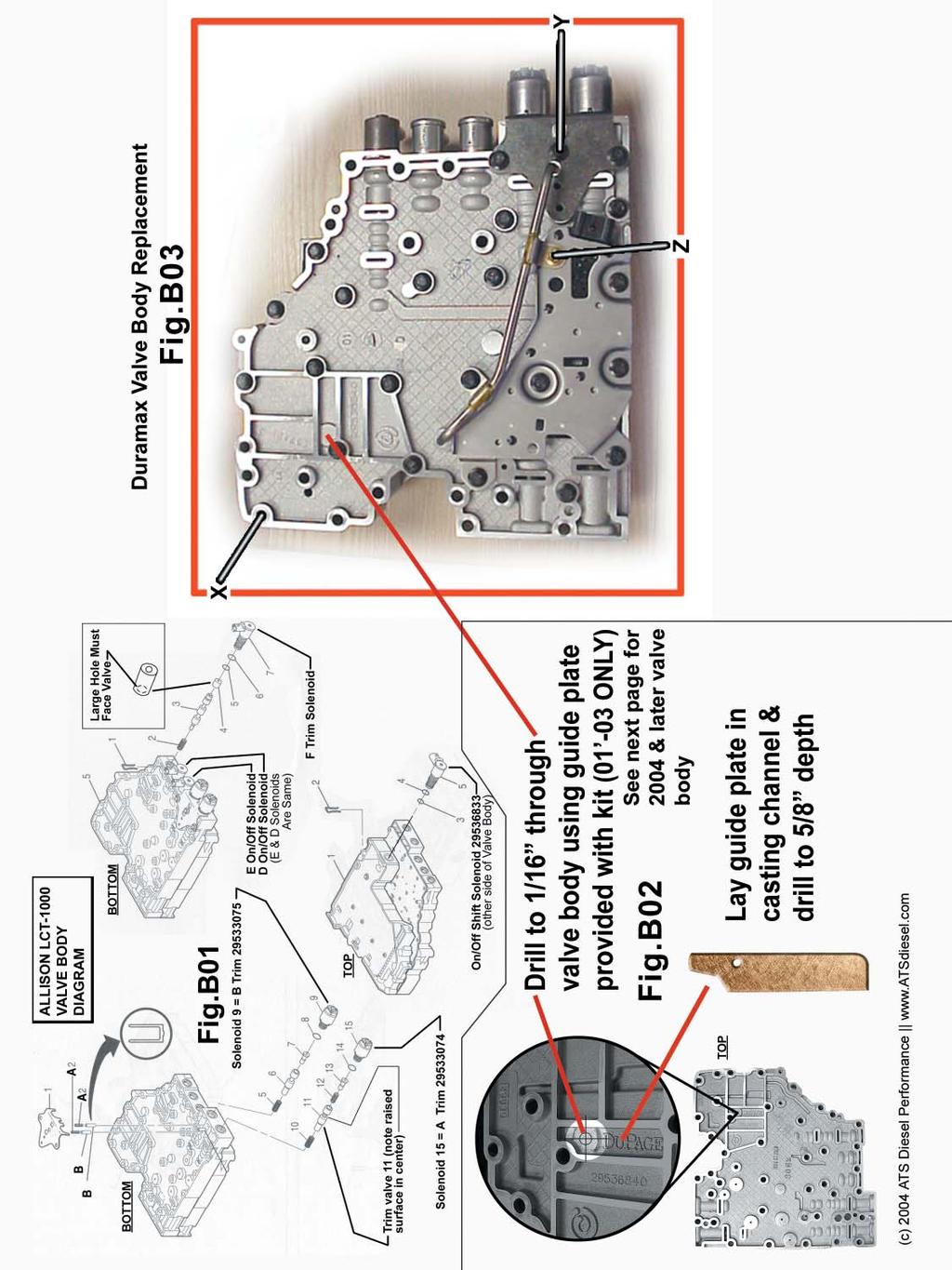
 15) For 2001 to early 2003 units you will need to drill a hole in the valve body with a 1/16 inch drill bit (approx.")

9 will fit 01 & later transmissions. The pigtail wrapped with wire conduit is used only on 04 & later units. For earlier units the wire (marked in picture) can be placed under the filter. (Fig.08) Fig.10 Fig.08 12) Insert the solenoid retainer clips to secure the wiring harness to the valve body. When installing the clips, it helps to move the solenoids slightly to seat the clips. (Fig.09) Fig.09 13) Install the two accumulator valves and springs (Use a light assembly grease to hold the accumulator pistons and springs in the valve body) and install the A-trim solenoid into the valve body. Note: Accumulator valves install first followed by the springs. (Fig.B01 <A2 & B> on separate sheet - page 17) While holding the A-trim solenoid flush with the valve body install the retaining plate. 14) After installing the retaining plate install the three bolts. Place pressure on the solenoids and push the retaining plate flush with the valve body, then tighten the bolts to 100 inch pounds. (Fig.10) 15) For 2001 to early 2003 units you will need to drill a hole in the valve body with a 1/16 inch drill bit (approx. 5/8 of an inch deep) using the guide plate as indicated by illustration (Fig.B02 & Fig.B03 on separate Sheet - page 17). After drilling the hole in the valve body clean out any debris that may be left over after drilling. This is a vent hole and is not critical, just be sure you go through the aluminum casting ONLY. (Use grease on the end of the drill bit to keep the shavings out of the interior port of the valve body). The guide plate should fit only one way when laid in the casting. (Fig.B02) For late 2003 or newer units DO NOT drill into the main valve body. The auxiliary valve body (Fig.C01 on separate sheet - page 18) will need to be drilled through the housing where indicated. Once this is complete the auxiliary valve body will be bolted back onto the main valve body. 16) You will need to modify the original stainless steel tube that was earlier removed from the valve body. Measure the stainless steel tube 1/2-inch from the bracket and cut using a tubing cutter. (Fig.11) Fig.11 9
 There should be a 1-3/8 gap between the two tubes after the cuts have been made.")

 20) Install the auxiliary valve body assembly and the two tubes into the lower valve body section.")
; the tubes will drop right in. Fig.")
 Place the two modified tubes into the new solenoid block provided; use the valve body for assistance")
10 17) After cutting the tube remove 1-3/8 inch from the other section of the tube. (Fig.12) Fig.14 Fig.12 18) There should be a 1-3/8 gap between the two tubes after the cuts have been made. Place the two modified tubes into the valve body and measure the gap between the sections. You must have exactly 1-3/8 inch between the two tube halves, and some modification to the length may be necessary to fit the valve body. (Fig.13) 20) Install the auxiliary valve body assembly and the two tubes into the lower valve body section. Be careful when installing the metal tubes into the lower valve body, gently tap the two tubes in equally where marked (Fig.15-1); the tubes will drop right in. Fig.15 21) Install the gold bolt (Note: Long bolt) (Fig.16-A) Fig.13 19) Place the two modified tubes into the new solenoid block provided; use the valve body for assistance when aligning the tubes to the block. (Fig.14) Fig.16 22) Install the other bolt that holds the tube and pressure manifold block to the lower valve body. (Fig.16-B) 23) Plug the 5 pin wiring harness into the pressure 10
 Install the internal filter and make one final check to ensure you have not over looked something or forgotten anything.")
11 manifold block (Fig.17-2) Fig.17 24) Take the time to do one last check over the valve body assembly, be sure all of the electrical connectors are plugged in and all of the bolts are tight. 25) Install the internal filter and make one final check to ensure you have not over looked something or forgotten anything. 26) Install the pan and gasket; this is also the time to install an aluminum deep pan if you have one. 27) Torque the pan bolts to 18-foot pounds of torque. 28) Add 6 quarts of transmission fluid to the transmission after securing the transmission pan to the case. 29) The transmission internal section is done; after the remaining portion of the ATS Co-Pilot kit is completed the transmission fluid needs to be checked immediately after start up. Note: It is common to have a check engine light immediately after start up due to low fluid level, after the transmission is full of fluid and a few ignition cycles the check engine light will reset. (2) Routing the external wiring harness 1) Plug the supplied wiring harness into the transmissions 20-pin connector located on the backside of the transmission. The supplied connector will plug in between the factory wiring harness and the transmission. Connect the factory 20-pin connector into the other end of the harness supplied. Be sure the two 20 pin connectors are securely locked into place, the two tabs on ether side of the connector make a snap sound when fully engaged. 2) After connecting the male and female ends of the wiring harness route the 10-foot section of the harness over the top of the transmission. The white connector will need to be routed to the inside of the cab. 3) Route the small white connector side of the wiring harness into the driver s side compartment through the firewall of the vehicle. There is an access hole in the firewall that can be enlarged to accommodate the harness. 4) Pull the wiring harness through the firewall just enough to connect it to the Co-Pilot module, ideally to the right side of the driver just below instrument cluster. 5) Plug the wiring harness into the Co-Pilot module; place it in a good location that can be easily accessed by the driver. Use the Velcro supplied to secure it to the dash. Use brake cleaner or solvent to clean the dash at area where the sticky Velcro will be used to attach the Co-Pilot controller. 30) IMPORTANT! Make sure to recheck the fluid level in the transmission after the vehicle is driven for a short distance, as it is common for the level to drop. 11
 1) Set the parking brake.")
 Place your foot on the brake pedal and press down to allow the interlock to disengage the shifter mechanism. 5) While your foot is on the brake, pull the gearshift selector to low gear.")

12 (3) Installing Wire for Tow/ Haul Mode NOTE: This section is optional; this feature is designed for performance acceleration only. If you are not concerned with performance acceleration this step can be skipped. (This option provides forced TCC operation during extreme acceleration, drag race mode) 1) Set the parking brake. 2) Tilt the wheel to full down position. 3) Place the key in the ignition and rotate clockwise one click to the accessories position. 4) Place your foot on the brake pedal and press down to allow the interlock to disengage the shifter mechanism. 5) While your foot is on the brake, pull the gearshift selector to low gear. This is the full down position. Fig.19 8) After removing the four screws, rotate the instrument cluster (pull the bottom of the cluster towards you). As you rotate the cluster, pull it towards you. You will be able to expose the connector. Use the illustration provided as a guide. The connector has one latch that needs to be depressed to release it from the dash. The connector is usually secured tightly. It s ok to exert some force removing it. Wiggling the connector from side to side helps. (Fig.20) 6) You are now ready to remove the dash panel. Use your fingers to pull the dash cover from the dash support. You may need to use some force to unlatch the keepers that hold the dash to the panel. Use the illustration provided as a guide. (Fig.18) Fig.20 Fig.18 7) You will need a 7mm socket or nut driver to loosen the four screws that secure the instrument cluster to the main support. Use the illustration provided to determine what screws to remove. (Fig.19) 9) Once the instrument cluster has been removed from the vehicle, place it on a bench for the final wire installation. Place the dash upside down on a bench or table. First, lay out a towel or something soft to prevent scratching the face of the cluster. After you have the instrument cluster lying on its face, remove the back plate. You can remove the backing plate by prying up on the locking tabs. Use a flat screwdriver or pointed object to get under the eight tabs, but make sure not to pry the tabs out too far, as they will break off with too much force. (Fig.21) 12
. You will need to solder the wire to the indicated pin located in figures 22 & 23.")


 Fig.22 Fig.")
13 Fig.21 10) A wire should be found in the kit depending on the year of the kit you receive. The kits will contain just a single wire. The 03 and later kit will contain a two-piece wire (heavier gauge with a small gauge connected to it.). You will need to solder the wire to the indicated pin located in figures 22 & 23. iron to heat up and easily melt the solder. The wire that you will receive should have a small amount of solder already melted (tinned) to it. This will ease in the attachment. Tin the iron with a small amount of solder, contact the point on the instrument cluster with the soldering iron, if there is any contaminates on the joint this will help dissolve them away. Now place the wire up on the point where you are going to solder to. Place a small amount of solder on the end of the iron again. While holding the wire in place, place the iron down on the wire and use a small amount of pressure to make the pieces contact. If needed a small amount of solder can be used to aid, but shouldn t be needed. Don t leave the iron on the wire too long, just about 2 to 3 seconds is all that is needed. On the cluster, make sure you don t allow the solder to contact across the other points, because the solder can make contact across the points and make an unwanted bridge. (Fig.24) Fig.22 Fig.24 If you have any problems with the installation of the wire, we also offer a replacement dash with the wire soldered in place in stock version or Escalade style, see our web site for details or give us a call. Fig.23 If you are not experienced with soldering, this is not a difficult procedure. A little patience is all that s needed. You will need a soldering iron of average size, (roughly 100w is adequate). Allow the soldering 11) You should now find a wire tie supplied in the kit for the 03 and later dashes. With the top of the cluster facing you and the face down you will see two holes in the cluster to the right. Curl up the wire tie around a pen, and then insert it through the holes so that it goes down in and back out of the cluster. Wrap the wire around the wire tie and zip up the tie to secure the wire in place. This will give the wire some support. Be VERY careful not to yank on the wire, as it will come off very easy and will destroy the trace on the board. 13

14 Run the remaining wire through a hole in the back cover and reattach the cover back into place. (Fig.25) Fig.25 Crimp the spade connectors on to the end of the wire, and the other spade connector on to the Blue wire coming out of the Co-Pilot harness. Run the Blue wire from the Co-Pilot harness up through the bottom of the dash into the area where the cluster sits. These need to be connected together now. You are now ready to install the cluster back into the dash. 12) When installing the instrument cluster into the dash, drop the blue wire down through the bottom so you can access it later. There are a variety of spots to place the wire through. Send it in the general direction of the mounting location for the box. 13) Reverse the previous steps, starting with step 8 to reinstall the instrument cluster and dash cover. 14) Connect the blue wire from the instrument cluster to the Co-Pilot wiring harness. (4) Co-Pilot Module Mounting Location Find a convenient location to mount the Co-Pilot module with in reach and view of the driver. The Co-Pilot interface must be within visual range of the driver as well as in easy reach. We have found the ideal place to locate the module is just to the right of the driver on the lower dash panel just above the right knee. Use the Velcro supplied to secure it to the dash. Run the wires from the Co-Pilot module through the firewall to be wired up to the PCM (Power train control module) and the transmission. (5) Connecting wiring harness to sensors -Black Wire- GND Ground Connect to any bolt/screw under the dash that is a good ground. The ground is the most commonly over looked part of a good installation. -Orange Wire- and -Brown Wire- Vehicle Speed Sensor Input/Output NOTE: This section is optional; this feature removes the 98mph speed limiter. If you are not concerned with this option or already have a speed limiter device installed or a programmer that already removes the speed limiter skip this section. This option is for off road use only and should never be used on public roads. ATS is not responsible for any accidents that may be a result from this modification or any accident that results from excessive speed. In some rare cases this feature may set an anti-brake light accompanied by a check engine light if the vehicle is operated above 98mph for extended periods of time. There are no negative side affects from this other than the check engine light. Locate the green and the orange wire from the Co- Pilot module, route it to the front left (Drivers side) side of the vehicle (Fig.26). 14
 from the radiator support shroud by")


15 Fig.26 Cut off any excess, leaving some slack. Remove the transmission control module (TCM) from the radiator support shroud by removing the two 10mm bolts from the cover indicated in (Fig.27). Fig.29 You will need to separate the connector at this point; the housing will part exposing the wires in the connector (Fig.30). Fig.27 After removing the bolts lift the computer and cover up exposing the bottom connector (Fig.28). Fig.30 Locate the yellow wire in pin location 27 on the bottom connector. Cut the wire about 2 inches from the connector where indicated. Splice the brown wire from the ATS wiring harness into the yellow wire coming from the connector from the TCM wire that was cut (Fig.31-1). Fig.28 Unplug the lower electrical connector from the computer by squeezing the lower connector and pulling outward on the connector. The connector will separate from the TCM (Fig.29). Fig.31 Splice the orange wire from the ATS wiring harness into the yellow wire that goes into the factory wiring 15

16 harness of the vehicle (Fig.31-2). It is advised to solder the joints at these two splices to ensure a good connection from the under hood environment. This is a low current high frequency circuit. This modification modifies the vehicle speed sensor circuit, if you have problems with the speedometer or brake lights this is the most likely area to look at first. -Green Wire- MAP Sensor Connect the green wire from the ATS wiring harness to the center wire on the map sensor (Fig.32). Fig.32 Use the T-tap connector supplied to splice into the center connector of the map sensor located on top of the engine Duramax is located on the right intake manifold; 2002-up Duramax is located in the intake tube in the center of the engine. This connection is critical; it is also subject to contamination due to its environment. We advise a good solder joint at this connection. Some power modules plug into this sensor, if there is an additional connector plugged into this sensor be sure your tap is closest to the sensor. On and later LLY Duramax Engines the wire is located in the main wiring harness on top of the engine. Locate the green wire which is found on the center pin in the map sensor connector (top of engine). Splice the green wire into it. 16
17 17

18 Fig.C01 18
19 Notes about first startup procedure after installation To avoid a fail safe condition and/or check engine light the recommended procedure is to fill the transmission with a minimum of 6 quarts (with stock pan) of fluid before startup. With the high capacity pan you will want to add 11 to 12 quarts before startup. Once the engine is started, allow it to run for 4-5 seconds and then shut off the ignition. Allow the vehicle to sit for 5-10 seconds and then restart the engine. This will purge the air from the system before the OEM computer detects the low pressure (therefore setting the check engine light and trouble code). Scan Tools Different scan tools can often be misleading. The only scan tool that ATS has found to be completely affective at thoroughly clearing trouble codes in the computer is the GM Tech II scanner and the Viewtronics hand-held scanner. Many other scan tools on the market display to the user that they are clearing the codes, when in-fact they are not. This condition of not completely clearing the codes has been exhibited repeatedly with the SnapOn scanners. Disconnecting the battery cables from the battery terminals WILL NOT clear the codes or the adaptive strategy that governs shift behavior. Feel free to contact our technical department for questions or details. Diagnostics The factory 20 pin connector on the back of the transmission can be plugged directly into the transmission after the Co-Pilot internals have been installed. This is one method that can be used to isolate possible electrical issues with the ATS external harness or Co-Pilot controller. If this procedure is used to diagnose any issues the speed limiter elimination feature (where brown and orange wires were spliced) as well as the vehicle s speedometer will not function and a anti-lock brake warning light will display. Theses conditions will automatically reset after the Co-Pilot external harness is reconnected and the vehicle is driven for a short period. Thank you for choosing the ATS Diesel Performance System! ATS Diesel Performance Limited Warranty Statement ATS Diesel Performance warrants the original purchaser that any parts purchased shall be free from defects in material and workmanship. A defect is defi ned as a condition that would render the product inoperable or seriously hindered in performance. This warranty does not cover deteriorating of plating, paint or any other coating. ATS liability is limited to the repair or replacement, at ATS option, of any warrantable product returned prepaid with a complete service history and proof of purchase to the factory. A valid proof of purchase is a dated bill of sale. Repaired or replaced, product will be returned to the customer, freight collect on a like for like part number basis. Accepted warranty units, which have been replaced, become the sole property of ATS. A Return Product Authorization number obtained in advanced from an ATS customer service representative must accompany products returned for warranty determination. ATS will be the fi nal authority on all warranty decisions. This warranty shall not apply to any unit which has been improperly stored or installed, subjected to misapplication, improper operating conditions, accidents, or neglect; or which has been improperly repaired, altered or otherwise mistreated by the owner or his agent. This warranty shall terminate at the end of 12 months in service with the original user. Labor cost incurred by the removal and replacement of an ATS product, while performing warranty work, will be the responsibility of the vehicle owner; in no case does the obligation of ATS Diesel Performance exceed the original purchase price of the product as indicated on the original bill of sale. Except as set forth in this warranty, ATS disclaims any implied warranty, including implied warranties of merchantability and fi tness for a particular purpose. ATS also disclaims any liability for incidental or consequential damages including, but not limited to, repair labor, rental vehicles, hotel costs or any other inconvenience costs. This warranty is in lieu of all warranties or guarantees, either expressed or implied, and shall not extend to any customer or to any person other than the original purchaser residing within the boundaries of the continental US or Canada. All materials in this packet are 2004 ATS Diesel Performance 19
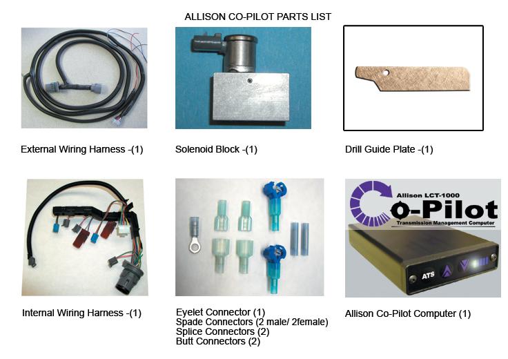
GM ALLISON 6 SPEED LCT-1000/2000/2400 CO-PILOT Parts list
 2006-10 GM ALLISON 6 SPEED LCT-1000/2000/2400 CO-PILOT Parts list Co-Pilot Computer (1) 601-800-4308 Solenoid Block (1) 601-109-4308 External Wiring Harness (1) 601-011-4308 Internal Wiring Harness (1)
GM ALLISON 5 SPEED LCT-1000/2000/2400 CO-PILOT PARTS LIST
 2001-2005 GM ALLISON 5 SPEED LCT-1000/2000/2400 CO-PILOT PARTS LIST Co-Pilot Computer (1) 601-800-4248 Solenoid Block (1) 601-109-4248C External Wiring Harness (1) 601-011-4248 Internal Wiring Harness
2006-UP GM ALLISON 6 SPEED LCT-1000/2000/2400 CO-PILOT Parts list
 02/21/08 COPLT-GM-06-UP 2006-UP GM ALLISON 6 SPEED LCT-1000/2000/2400 CO-PILOT Parts list Co-Pilot TM Computer (1) Solenoid Block (1) External Wiring Harness (1) Secondary Wiring Harness (1) Installation
Installation Manual v1.0: Dodge 68RFE Automatic Transmission. Please read all instructions before the installation of the ATS Co-Pilot
 09/30/11 601-900-2356-INST Installation Manual v1.0: 2010-11 Dodge 68RFE Automatic Transmission Please read all instructions before the installation of the ATS Co-Pilot Thank you for purchasing the ATS
12/05/2012 Lockup Co-Pilot Instructions INST. Installation Manual v1.6: Dodge 68RFE Automatic Transmission
 Installation Manual v1.6: 2007.5-09 Dodge 68RFE Automatic Transmission Please read all instructions before the installation of the ATS Co-Pilot Thank you for purchasing the ATS Co-Pilot transmission management
BD BrakeLoc EBP Valve Controlol Ford Powerstroke (Manual Transmissions)
") 3 January 2006 BD BrakeLoc (Ford Powerstroke Manual Transmission) P/N # 1030755 1 BD BrakeLoc EBP Valve Controlol Ford Powerstroke (Manual Transmissions) Part# 1030755 * Please read this instruction manual
3 January 2006 BD BrakeLoc (Ford Powerstroke Manual Transmission) P/N # 1030755 1 BD BrakeLoc EBP Valve Controlol Ford Powerstroke (Manual Transmissions) Part# 1030755 * Please read this instruction manual
Installation Manual for Ford Power Stroke Version 1.4. Please read all instructions before the installation of the ATS Co-Pilot Module
 6/12/08 COPLT-F-99-02-INST Installation Manual for 1999-2003 Ford Power Stroke Version 1.4 Please read all instructions before the installation of the ATS Co-Pilot Module Thank you for purchasing the ATS
Installation Manual v2.5: Dodge 1994 to 2005 Ford 1994 to 2002-½ For Full Lock-Up And/Or Exhaust Brake Control
 Installation Manual v2.5: Dodge 1994 to 2005 Ford 1994 to 2002-½ For Full Lock-Up And/Or Exhaust Brake Control Please read all instructions before the installation of the ATS Commander Module Thank you
For electronically controlled E4OD and 4R100 automatic transmissions ** READ ALL INSTRUCTIONS BEFORE INSTALLATION **
 26 August 2005 Ford PressureLoc #1060380 1 BD Ford PressureLoc Installation Manual For electronically controlled E4OD and 4R100 automatic transmissions Part#: 1060380 ** READ ALL INSTRUCTIONS BEFORE INSTALLATION
Part# Accessory Power Distribution Module
 7 February 2006 Power Pod (1038800) Page 1 BD Powe r Pod Installation Instructions Part# 1038800 Accessory Power Distribution Module Power Pod Specifications: Eliminate multiple T-taps and splices on OEM
BD PRESSURELOC INSTALLATION MANUAL
 May 03 BD PressureLoc #1030377 1 BD PRESSURELOC INSTALLATION MANUAL READ ALL INSTRUCTIONS BEFORE INSTALLATION May 03 BD PressureLoc #1030377 2 KIT COMPONENTS Switched 12V wiring harness Control Valve Attachments
2004½-2007 Dodge 5.9L Cummins 24v ISBe (600 motors only)
") 31 October 2006 Part # 1045235-1 - BD Supe r B Single 2004½-2007 Dodge 5.9L Cummins 24v ISBe (600 motors only) Part # 1045235 PLEASE READ ALL INSTRUCTIONS BEFORE INSTALLATION. Note: This turbo system is
31 October 2006 Part # 1045235-1 - BD Supe r B Single 2004½-2007 Dodge 5.9L Cummins 24v ISBe (600 motors only) Part # 1045235 PLEASE READ ALL INSTRUCTIONS BEFORE INSTALLATION. Note: This turbo system is
van Aaken SmartBox Installation Instructions
 van Aaken SmartBox Installation Instructions Vehicle: VW Golf PD Engine: 1.9 TDi 100 Bhp Year: 2004-2006 Our Website, www.vanaaken.com, has further information on all of our new products. Every effort
BD SUPER B SPECIAL Dodge 5.9L Cummins 24v ISB
 1 This turbo is intended for high performance applications and is not to be used for towing applications BD SUPER B SPECIAL 1994-2002 Dodge 5.9L Cummins 24v ISB Part# 1045120 PLEASE READ ALL INSTRUCTIONS
LB LB LLY LLY 1000
 6 November 2006 GMC/Chevy Allison Performance Transmission 1 BD PERFORMANCE TRANSMISSION Allison Installation Instructions 2WD Transmissions 4WD Transmissions 1064702 2000-2003 LB7 1000 1064704 2000-2003
BD POWER SHORT SHIFTER Dodge Speed Dodge Speed Dodge Speed.
 June 05 Cummins Short Shift Kit (1031050/1031055/103156) 1 BD POWER SHORT SHIFTER for Dodge Cummins 1998-2005 Manual Transmissions Application Chart 1031056 Dodge 1998-2002 5 Speed 1031050 Dodge 2000-2002
Installation Manual v1.6: Dodge 68RFE Automatic Transmission. Please read all instructions before the installation of the ATS Co-Pilot
 Installation Manual v1.6: 2007.5-09 Dodge 68RFE Automatic Transmission Please read all instructions before the installation of the ATS Co-Pilot Thank you for purchasing the ATS Co-Pilot transmission management
Allison Lockup Controller
 19 February 2018 1031311/1031312/1031313 Allison Transmission Lockup and Pressure Module (I-00413) 1 Allison Lockup Controller Transmission Lockup and Pressure Controller 1031311 1031312 1031313 2001-2010
Dodge 24v ISBe
 BD SUPER B 2003-2004 Dodge 24v ISBe (Non 600 motors) Part # 1045230 PLEASE READ ALL INSTRUCTIONS BEFORE INSTALLATION This turbo system is not compatible with an AFE intake system WITHOUT MODIFICATIONS.
GMC/Chevy LB7 Duramax BD Remote Mount Exhaust Brake
 16 October 2006 GMC/Chevy Duramax #1024118 / 1024119 / 1024118DA / 1024119DA 1 2001-20042004 GMC/Chevy LB7 Duramax BD Remote Mount Exhaust Brake Part Number Application 1024118 Duramax with 3.5 Stock Exhaust,
Installation Manual for Dodge Cummins Version 1.2. Please read all instructions before the installation of the ATS Co-Pilot Module
 COPLT-D-98.5-02-INST Installation Manual for 1998.5-2002 Dodge Cummins Version 1.2 Please read all instructions before the installation of the ATS Co-Pilot Module Thank you for purchasing the ATS Co-Pilot
Retro it Steering Column
 Retro it Steering Column INSTALLATION INSTRUCTIONS for 1976-86 CJ5 & CJ7 FOR PART NUMBER S: 1520800010, 1520800020, 1520800051, 1526800010, 1526800020, 1526800051 S I NCE 1986 Instruction # 8000000010
Installation Manual for Dodge 24V Cummins Version 3.1. Please read all instructions before the installation of the ATS Co-Pilot
 10/1/12 601-900-2218-INST Installation Manual for 1998.5-2002 Dodge 24V Cummins Version 3.1 Please read all instructions before the installation of the ATS Co-Pilot Thank you for purchasing the ATS Co-Pilot
Banks SmartLock. THIS MANUAL IS FOR USE WITH system 55270
 owner s manual with installation instructions Banks SmartLock 2003-Early 2004 Dodge 5.9L CUMMINS TURBO DIESEL TRUCKS THIS MANUAL IS FOR USE WITH system 55270 Gale Banks Engineering 546 Duggan Avenue Azusa,
Ford Mustang V6 OEM-Style Fog Light Kit Parts List: Quantity: Tool List:
 2015-2017 Ford Mustang V6 OEM-Style Fog Light Kit Parts List: Quantity: Tool List: LED Foglights/ Bezels 2 Flat head & Phillips screwdriver (if you ordered part#3600) Ratchet & Socket set OR Wiring harness
Equipped with AEM Dryflow Filter No Oil Required! INSTALLATION INSTRUCTIONS PART NUMBER C (GUN METAL GRAY FINISH) NISSAN SENTRA 1.
 NISSAN SENTRA 1.") Equipped with AEM Dryflow Filter No Oil Required! INSTALLATION INSTRUCTIONS PART NUMBER 21-799C (GUN METAL GRAY FINISH) 2014-16 NISSAN SENTRA 1.8L 1 ITEM NO. PART NUMBER DESCRIPTION QTY. 1 21-2157D AIR
Equipped with AEM Dryflow Filter No Oil Required! INSTALLATION INSTRUCTIONS PART NUMBER 21-799C (GUN METAL GRAY FINISH) 2014-16 NISSAN SENTRA 1.8L 1 ITEM NO. PART NUMBER DESCRIPTION QTY. 1 21-2157D AIR
I N S TA L L AT I O N
 I N S TA L L AT I O N 5008 fits: H-D: '80-Up Electra glide, tour glide, road king, road glide or street glide PartS Included 1 Right Fork Mount Assembly 1 Left Fork Mount Assembly 2 H3 Driving Light Assemblies
Torqueflite Manual/Automatic Valve Body
 TCI 122400 Torqueflite Manual/Automatic Valve Body This valve body can be installed in a few hours by carefully following directions. Read all instructions first to familiarize yourself with the parts
LB7/ LLY Allison 5 speed transmissions
 PPEdiesel.com STAGE 4 TRANSMISSION KIT INSTALLATION GUIDE 2001-2005 LB7/ LLY Allison 5 speed transmissions Technical Support (714) 985-4825 Rev: 01/31/18 v7 DISCLAIMER OF LIABILITY This is a performance
Installation Instructions. Application List Dodge 24V PLEASE READ ALL INSTRUCTIONS BEFORE INSTALLATION
 1 BD DODGE CUMMINS 03-055 C O O L - I T I N T E R C O O L E R Installation Instructions Application List 2003-2006 Dodge 24V 1042510 PLEASE READ ALL INSTRUCTIONS BEFORE INSTALLATION KIT CONTENTS: Please
Installation Instructions For #64060 Striker I Power Module GMC/Chevrolet Duramax LB7 Diesel
 2501 Ludelle Street Fort Worth, Texas 76105 817-244-6212 Phone 817-244-4024 Fax 888-350-6588 Sales 800-423-9696 Tech E-mail: painless@painlessperformance.com Web: www.painlessperformance.com Installation
INSTALLATION INSTRUCTIONS CATCH CAN KIT
 INSTALLATION INSTRUCTIONS CATCH CAN KIT FORD FOCUS Document: 19-0150 Support: info@radiumauto.com STEPS 1-19 COVER THE PCV SIDE CATCH CAN KIT (P/N: 20-0315) STEPS 20-32 COVER THE CRANKCASE CATCH CAN KIT
Installation Instructions Z-Gate Shifter
 Installation Instructions Z-Gate Shifter Part Number 80681 1998, 2001 by B&M Racing and Performance Products The B&M Z-Gate shifter can be used in vehicles equipped with most popular three speed automatic
All cores due 30 days after invoice date - no credit after 60 days.
 NO WARRANTY STATEMENT High performance parts & products no warranty policy: The purchaser understands and recognizes that high performance diesel products and services sold by INDUSTRIAL INJECTION SERVICE.
17 August Cool Down Timer Page 1. Part# Application Chart --
 17 August 2005 1081150 Cool Down Timer Page 1 BD Cool Down Timer Part# 1081150 Application Chart -- Dodge Cummins 1996-2005 Ford F Series (7.3L) 1994-2003 Ford F Series (6.0L) 2003-2005 GMC/Chevy Duramax
Stage4 Installation Guide STAGE 4 TRANSMISSION KIT INSTALLATION GUIDE Allison LB7/ LLY only for 5 speed trasmissions
 STAGE 4 TRANSMISSION KIT INSTALLATION GUIDE 2001-2005 Allison LB7/ LLY only for 5 speed trasmissions DISCLAIMER OF LIABILITY This is a performance product which can be used with increased horsepower above
Z-Gate Universal Shifter
 Installation Instructions Z-Gate Universal Shifter Fits: GM, Ford, Lincoln and Chrysler Transmissions See Application Guide for Specific Applications Part #80681 Rev 06/01/2018 WORK SAFELY! For maximum
Installation Manual for Dodge 12V Cummins Version 3.7. Please read all instructions before the installation of the ATS Co-Pilot
 Installation Manual for 1994-1998 Dodge 12V Cummins Version 3.7 Please read all instructions before the installation of the ATS Co-Pilot Thank you for purchasing the ATS Co-Pilot. This manual is to assist
Depress each tab as you pull the bezel off. The bezels are tight. L.H. shown.
 2013-2014 Ford Mustang V6 & Boss 302 Lower Valance Fog Light Kit Parts List: Quantity: Tool List: Fog light & bulb with bracket 2 Flat head & Phillips screwdriver Black bezels 2 Ratchet & Socket set OR
Return to Instruction Sheet index TCI Installation Instructions for Turbo Hydramatic 350C & 250C
 Page 1 of 6 Return to Instruction Sheet index TCI 326300 Installation Instructions for Turbo Hydramatic 350C & 250C NOTE: This kit was not intended for installation in transmissions that are in poor general
Installation Instructions - ECS Tuning Vent Pod Vacuum/Boost Gauge Kit
 Installation Instructions - ECS Tuning Vent Pod Vacuum/Boost Gauge Kit This tutorial is provided as a courtesy by ECS Tuning. Part Number for (2005-2008) Proper service and repair procedures are vital
Torqueflite Trans-Scat Kit
 TCI 220000 Torqueflite Trans-Scat Kit This kit can be installed in a few hours by carefully following directions. Read all instructions first to familiarize yourself with the parts and procedures. Work
6 November Ford Powerstroke 6.0/7.3L X-Monitor 1 BD X-MONITOR Ford 6.0/7.3L Powerstroke
 6 November 2006 1087200-7210 Ford Powerstroke 6.0/7.3L X-Monitor 1 BD X-MONITOR 1999-2007 Ford 6.0/7.3L Powerstroke I n s t a l l a t i o n M a n u a l Date Purchased Purchased from Installed by READ THIS
Installation Instructions for Chevrolet Colorado, GMC Canyon, LT, Z71, With Factory Fog Lights
 Installation Instructions for 2015-2018 Chevrolet Colorado, GMC Canyon, LT, Z71, With Factory Fog Lights This kit is designed to allow use of your factory fog light operation along with an addition auxiliary
TCI Trans-Scat
 Page 1 of 5 Return to Instruction Sheet index TCI 350000 Trans-Scat Installation Instructions For TURBO HYDRAMATIC 350 This kit will allow you to reprogram your transmission to meet your driving needs
BD Turbo Mount Air Exhaust Brake
 29 June 2005 Ford Powerstroke (1999-2003 7.3L) Air Exhaust Brake P/N# 2023144 1 1999-2002 Ford d 7.3L Powerstrokes oke BD Turbo Mount Air Exhaust Brake Part# 2023144 Serial # Date Purchased Purchased from
DEMON CARBURETOR MANUAL CHOKE KIT #421441
 DEMON CARBURETOR MANUAL CHOKE KIT #421441 CHOKE INSTALLATION INSTRUCTIONS LIT703 This manual choke kit is designed to be used on any Demon Carburetor with a choke tower. This covers the Road Demon Jr.
Installation Instructions
 Installation Instructions Jeep JK Unlimited (2007 Present) Mounting Bracket and Air Line System Kit for ARB On-Board Twin Air Compressor (CKMTA12) Made in the USA Kit Contents: 1 Bracket for ARB Compressor
UNIVERSAL GAUGE WIRE HARNESS
 2650-1797-00 UNIVERSAL GAUGE WIRE HARNESS For Installing Auto Meter Electric Speedometer, Tachometer, And Short Sweep Electric Oil Pressure, Water Temperature, Fuel Level, and Volt Meter Gauges. This harness
Installation Manual TWM Performance Short Shifter Cobalt SS/SC, SS/TC, HHR SS, Ion Redline and Saab 9-3
 Page 1 Installation Manual TWM Performance Short Shifter Cobalt SS/SC, SS/TC, HHR SS, Ion Redline and Saab 9-3 Please Note: It is preferable to park on a flat surface, as you will have to engage and disengage
VW/AUDI MK7 VEHICLES
 Installation Manual P/N 1-301-1708-01 (STAGE 2+ FUEL KIT) P/N 1-301-1708-02 (STAGE 3+ FUEL KIT) VW/AUDI MK7 VEHICLES Warning: This installation is not recommended for a novice or the new guy in the shop.
Installation Instructions For #64066 Striker I Power Module Ford Powerstroke 6.0L Diesel Copyright
 Installation Instructions For #64066 Striker I Power Module 2003-2006 Ford Powerstroke 6.0L Diesel 2 nd Edition August 2007 Copyright 2006 by Perfect Performance Products, LLC 2501 Ludelle Street Fort
Installation Instructions
 1 BD DODGE CUMMINS PERFORMANCE E X H A U S T M A N I F O L D Installation Instructions Application List 1994-1998 12V 1045980 1998½-2002 24V 1045985 PLEASE READ ALL INSTRUCTIONS BEFORE INSTALLATION KIT
Equipped with AEM Dryflow Filter No Oil Required! INSTALLATION INSTRUCTIONS PART NUMBER C (Gun Metal Grey Finish) 2015 Ford Mustang 5.
 2015 Ford Mustang 5.") Equipped with AEM Dryflow Filter No Oil Required! INSTALLATION INSTRUCTIONS PART NUMBER 21-745C (Gun Metal Grey Finish) 2015 Ford Mustang 5.0L 1 2 Read and understand these instructions BEFORE attempting
Equipped with AEM Dryflow Filter No Oil Required! INSTALLATION INSTRUCTIONS PART NUMBER 21-745C (Gun Metal Grey Finish) 2015 Ford Mustang 5.0L 1 2 Read and understand these instructions BEFORE attempting
Equipped with AEM Dryflow Filter No Oil Required!
 Equipped with AEM Dryflow Filter No Oil Required! INSTALLATION INSTRUCTIONS PART NUMBER: 21-9210 1994-2002 DODGE Ram 2500 Pickup L6-5.9L DSL C.A.R.B. E.O. # D-670 1994-2002 DODGE Ram 3500 Pickup L6-5.9L
Remove the 3-11mm nuts holding mirror on. Don t drop the nuts!
 2005-2012 Ford Mustang Puddle Lamp Kit Parts List: Quantity: Tool List: LED Lamps 2 Flat head screwdriver Seals 2 Ratchet & Socket set OR Nuts 2 Adjustable Wrench Wiring harness 1 Drill & 11/16 th bit
BD Remote Mount Air Exhaust Brake
 17 April 2006 1023310/ 1023311 GMC C4500/5500 Exhaust Brake 1 2003-05 GMC Duramax C4500/5500 BD Remote Mount Air Exhaust Brake Part Number Application 1023310 GMC C4500/5500 Brake (without Air Compressor)
INSTALLATION INSTRUCTIONS PART NUMBER C (Gun Metal Gray Finish)
") Equipped with AEM Dryflow Filter No Oil Required! INSTALLATION INSTRUCTIONS PART NUMBER 21-765C (Gun Metal Gray Finish) 2014-16 MAZDA 3 2.0L *Manual Transmission Only 1 ITEM NO. PART NUMBER DESCRIPTION
Equipped with AEM Dryflow Filter No Oil Required! INSTALLATION INSTRUCTIONS PART NUMBER 21-765C (Gun Metal Gray Finish) 2014-16 MAZDA 3 2.0L *Manual Transmission Only 1 ITEM NO. PART NUMBER DESCRIPTION
Installation Instructions. QuickSilver Shifter. Fits: GM, Ford, Chrysler Transmissions See Application Guide for Specific Applications Part # 80683
 Installation Instructions QuickSilver Shifter Fits: GM, Ford, Chrysler Transmissions See Application Guide for Specific Applications Part # 80683 WORK SAFELY! For maximum safety, perform this installation
Installation Instructions Jeep CJ-7
 Retrofit Steering Column Installation Instructions 1976-86 Jeep CJ-7 For Part # s 1520800010, 152800020, 1520800051 www.ididitinc.com 610 S. Maumee St., Tecumseh, MI 49286 (517) 424-0577 (517) 424-7293
INSTALLATION INSTRUCTIONS
 Equipped with AEM Dryflow Filter No Oil Required! INSTALLATION INSTRUCTIONS PART NUMBER AEM-21-805C (GUN METAL GRAY FINISH) 2016.5-19 CHEVROLET CRUZE 1.4T 1 ITEM NO. PART NUMBER DESCRIPTION QTY. 1 21-2038DK
INSTALLATION INSTRUCTIONS CATCH CAN KIT
 INSTALLATION INSTRUCTIONS CATCH CAN KIT FORD FIESTA ST Document: 19-0175 Support: info@radiumauto.com STEPS 1-14 COVER THE PCV SIDE CATCH CAN KIT (P/N: 20-0377) STEPS 15-35 COVER THE CRANKCASE CATCH CAN
Installation Manual v3.0: Dodge Cummins. Please read all instructions before the installation of the ATS Co-Pilot
 Installation Manual v3.0: 2004-2005 Dodge Cummins Please read all instructions before the installation of the ATS Co-Pilot Thank you for purchasing the ATS Co-Pilot Torque converter/exhaust brake controller.
TH400 STREETFIGHTER SERIES VALVE BODY MANUAL/AUTO VALVE BODY INSTALLATION INSTRUCTIONS
 1 INSTRUCTIONS TH400 STREETFIGHTER SERIES VALVE BODY 1965-87 MANUAL/AUTO VALVE BODY INSTALLATION INSTRUCTIONS TCI 222400 TCI 222400 ALLOWS AUTOMATIC SHIFT FEATURES IN THE DRIVE POSITION Thank you for choosing
Installation Tips Crimestopper/ProStart Remote Start system + PLJX + DLRM + SPDT (for GM vehicles) T0760 v1.1 updated 2/5/14
 T0760 v1.1 updated 2/5/14") Installation Tips Crimestopper/ProStart Remote Start system + PLJX + DLRM + SPDT (for GM vehicles) T0760 v1.1 updated 2/5/14 Thank you for purchasing your remote start from MyPushcart.com - an industry
Installation Tips Crimestopper/ProStart Remote Start system + PLJX + DLRM + SPDT (for GM vehicles) T0760 v1.1 updated 2/5/14 Thank you for purchasing your remote start from MyPushcart.com - an industry
Dfuser T/C Lock-Un Lock
 Dfuser T/C Lock-Un Lock Performance Diesel and more! For more information visit our website at: http://www.dfuser.com Page 1 of 6 User Guide This harness overrides and monitors Torque Converter (T/C) lockup
Disconnect the APP sensor harness connector. See Fig. 4. Remove the accelerator pedal mounting nuts. Remove the APP assembly.
 ENGINE CONTROLS - REMOVAL, OVERHAUL & INSTALLATION - 6.6L DIESEL... Page 1 of 41 FUEL SYSTEMS ACCELERATOR PEDAL POSITION SENSOR Removal & Installation Disconnect the APP sensor harness connector. See Fig.
#TL T EA888 GEN 3 FUELING SYSTEM/ INSTALLATION INSTRUCTIONS
 #TL100069 2.0T EA888 GEN 3 FUELING SYSTEM/ INSTALLATION INSTRUCTIONS Notes: These instructions were written for a North American specification MkVII GTI. Other models, like the Golf R, are similar. When
Owner s Manual Ford Powerstroke 7.3 liter CAUTION: THIS IS A HIGH PERFORMANCE PRODUCT. USE AT YOUR OWN RISK.
 Owner s Manual 1994 2003 Ford Powerstroke 7.3 liter CAUTION: THIS IS A HIGH PERFORMANCE PRODUCT. USE AT YOUR OWN RISK. Edge Products Inc distributed by BD Power Evolution FORD Powerstroke 7.3 liter - 1
Special Note About The JDM High Performance Water Pump:
 Page 1 of 30 JDM Engineering, Inc. home Call Us! 732-780- 0770 back to Installation Instructions Electric Fan Upgrade Kit Electric Fan Wiring Diagram Thank you for your purchase of the JDM Engineering
Installation Instructions PowerBoard Automatic Retracting Running Board
 Installation Instructions PowerBoard Automatic Retracting Running Board Vehicle Application Chevy Silverado/GMC Sierra Extended Cab Diesel 2011 and newer Part Number: 75147-15 Chevy Silverado/GMC Sierra
Installation Tips for your Remote Start system (for RS4LX>GMBP for GM vehicles)
") Installation Tips for your Remote Start system (for RS4LX>GMBP for GM vehicles) Thank you for purchasing your remote start from MyPushcart.com - an industry leader in providing remote starts to doit-yourself
Installation Tips for your Remote Start system (for RS4LX>GMBP for GM vehicles) Thank you for purchasing your remote start from MyPushcart.com - an industry leader in providing remote starts to doit-yourself
PRO RATCHET UNIVERSAL SHIFTER
 Installation Instructions PRO RATCHET UNIVERSAL SHIFTER Fits: GM, Ford and Chryslers w/automatic Transmission See Application Guide for Specific Vehicles Catalog # 80842 WORK SAFELY! For maximum safety,
FORD E4OD/4R100 AUTOMATIC TRANSMISSION EQUIPPED VEHICLES
 owners manual with installation instructions TransCommand FORD E4OD/4R100 AUTOMATIC TRANSMISSION EQUIPPED VEHICLES THIS MANUAL IS FOR USE WITH SySTEM 62560 & 62570 also available from banks Power for 94-03
Installation Instructions PowerBoard Automatic Retracting Running Board
 Installation Instructions PowerBoard Automatic Retracting Running Board Vehicle Application Chevy Silverado/GMC Sierra Extended Cab 2007 and newer (excluding 2011 Diesels) Part Number: 75123-15 Chevy Silverado/GMC
INSTALLATION INSTRUCTIONS
 HIGH FLOW AIRFLOW METER INSTALLATION INSTRUCTIONS PART NUMBER D763-1600A APPLICATION: 2001-06 E46 M3 Parts List: Hose clamp 64Z (7) Plastic Rivets Air Filter Temp Sensor & Harness (2) Button Head Screws
PRXB EXHAUST BRAKE MAXIMUM EXHAUST FLOW DESIGN
 MAXIMUM EXHAUST FLOW DESIGN PRXB EXHAUST BRAKE C44072/C44073/C44074/C44075/C44076 APPLICATION: 994-2002 DODGE RAM TRUCKS W/5.9L CUMMINS DIESEL ENGINES WITH MANUAL & AUTOMATIC TRANSMISSIONS STOCK DODGE
12 September 2012 Valve Body # , , ,
 12 September 2012 Valve Body # 1030416, 1030417, 1030418, 1030419 1 BD VALVE BODY For 1996-2004 Dodge 5.9L 12V/24V Cummins Trucks -- I n s t a l l a t i o n I n s t r u c t i o n s -- 1030416 1996-1998
Installation Instructions
 Installation Instructions Jeep JK 2-Door (2011 Present) Mounting Bracket and Air Line System Kit for ARB On-Board Twin Air Compressor (CKMTA12) Made in the USA Kit Contents: 1 Flat Bracket 1 Formed Bracket
TCI TRANS-SCAT
 Page 1 of 9 Return to Instruction Sheet index TCI 360000 TRANS-SCAT Installation Instructions for FORD C-6 Transmissions TCI s TRANS-SCAT kit will allow you to calibrate the performance of your transmission.
DODGE SRT-4 PART NUMBER P (with Turbo Toys) P (without Turbo Toys) P (Stage 2 to Stage 3R Upgrade Kit)
 P (without Turbo Toys) P (Stage 2 to Stage 3R Upgrade Kit)") INFORMATION SHEET Stage 3R Turbo Upgrade Kit Components (1) Stage 3R PCM (4) 682 cc/min Fuel Injectors* (1) 3.0 bar MAP Sensor* (1) 3.0 bar TIP Sensor* (1) Block-off Connector for PCM (1) Mopar TD05HR
INFORMATION SHEET Stage 3R Turbo Upgrade Kit Components (1) Stage 3R PCM (4) 682 cc/min Fuel Injectors* (1) 3.0 bar MAP Sensor* (1) 3.0 bar TIP Sensor* (1) Block-off Connector for PCM (1) Mopar TD05HR
PLEASE READ BEFORE CALLING OR RETURNING PRODUCT. EXTREMELY IMPORTANT!!!
 Thank you for your purchase of WeaponX Smart Direct Fire Ignition Coil System for your vehicle. The following are the instruction manuals for your ignition system kit. Please read carefully and enjoy your
INSTALLATION. Note: Not all parts will be used in the installation of this product. -cont.-
 5005 Fits: 06-up FLHX, 04-up Screamin Eagle Ultra Classic Electra Glide & Screamin Eagle Electra Glide Classic, '97-up FLHT, FLHTC, FLHTCU, FLHR PartS Included 1 Right Driving Light Assembly 1 Left Driving
Installation Instructions PowerBoard Automatic Retracting Running Board
 Installation Instructions PowerBoard Automatic Retracting Running Board Vehicle Application Dodge Ram 1500 Crew Cab 2009 - Current : 75138-15 Dodge Ram 2500/3500 & HD Crew Cab 2010 - Current : 75138-15
9/8/ ½-2004 Dodge 5.9L Cummins Flow-MAX Lift Pump Retro Kit # ½ L DODGE CUMMINS. Installation Instructions
 9/8/2008 1998½-2004 Dodge 5.9L Cummins Flow-MAX Lift Pump Retro Kit # 1050302-1 - 1998½-2004 5.9L DODGE CUMMINS RETRO FIT INTAKE PUMP Kit Installation Instructions P/N# 1050302 PLEASE READ ALL INSTRUCTIONS
INSTALL MANUAL D o d g e 1 2 v 6 B T A PLEASE READ ALL INSTRUCTIONS BEFORE INSTALLATION.
 PN#1045310 12V Dodge Twin Turbo Kit (I-00273) 1 INSTALL MANUAL BD Twin Turbo Kit 1994-1 9 9 8 D o d g e 1 2 v 6 B T A Part# 1045310 PLEASE READ ALL INSTRUCTIONS BEFORE INSTALLATION. * Picture as shown
INSTALLATION INSTRUCTIONS CATCH CAN KIT
 INSTALLATION INSTRUCTIONS CATCH CAN KIT FORD FOCUS Document: 19-0150 Support: info@radiumauto.com STEPS 1 TO 19 COVER THE PCV SIDE CATCH CAN KIT (P/N: 20-0315) STEPS 20-32 COVER THE CRANKCASE CATCH CAN
2010+ Camaro Triple-Threat Wet Nitrous System
 2010+ Camaro Triple-Threat Wet Nitrous System This Installation Guide is to be used with the Ny-Trex Owner s Manual. (Refer to the Owner s Manual for installation tips, safety tips, and precautions) 1.
Installation Instructions for Lingenfelter GM 2500 Suburban & Yukon XL Auxiliary Fan System (with AC clutch controlled fan output)
") Installation Instructions for Lingenfelter 2007-2013 GM 2500 Suburban & Yukon XL Auxiliary Fan System (with AC clutch controlled fan output) PN L300080607 Revision - 1.1 Lingenfelter Performance Engineering
Installation Instructions for Lingenfelter 2007-2013 GM 2500 Suburban & Yukon XL Auxiliary Fan System (with AC clutch controlled fan output) PN L300080607 Revision - 1.1 Lingenfelter Performance Engineering
3 WRX/STI TURBO INLET HOSE
 3 WRX/STI TURBO INLET HOSE Thank you for purchasing this PERRIN product for your car! Installation of this product should only be performed by persons experienced with installation of aftermarket performance
Installation Tips for your Crimestopper/ProStart Remote Start system (add-on for GM vehicles) v1.02 updated 1/16/2013
 v1.02 updated 1/16/2013") Installation Tips for your Crimestopper/ProStart Remote Start system (add-on for GM vehicles) v1.02 updated 1/16/2013 Thank you for purchasing your remote start from MyPushcart.com - an industry leader
Installation Tips for your Crimestopper/ProStart Remote Start system (add-on for GM vehicles) v1.02 updated 1/16/2013 Thank you for purchasing your remote start from MyPushcart.com - an industry leader
Table of Contents. 4 Getting Started 4 About the Juice 5 Safety Terms 5 Product Registration 6 Important Notes 7 Truck Orientation
 Table of Contents 4 Getting Started 4 About the Juice 5 Safety Terms 5 Product Registration 6 Important Notes 7 Truck Orientation 8 Juice Installation 1999-2003 (7.3L) 8 Supplied Items & Required Tools
The steering column is of a modular construction and features easy to service electrical switches.
 file://c:\tso\tsocache\vdtom_5368\svk~us~en~file=svkb4a01.htm~gen~ref.htm Page 1 of 3 Section 11-04A: Steering Column, Ranger DESCRIPTION AND OPERATION 1997 Ranger Workshop Manual Steering Column NOTE:
Turn Signal Kit Installation Instructions for Model A Fords & Other Antique Vehicles
 Turn Signal Kit Installation Instructions for Model A Fords & Other Antique Vehicles Lifetime Technical Support support@logolites.com 770-476-7322 www.logolites.com Manual 100-0005N Thank you for purchasing
Light Truck MegaShifter
 Installation Instructions Light Truck MegaShifter The B&M Light Truck Megashifter shifter is designed to be used in most light trucks equipped with most popular three speed or four speed automatic transmissions.
GTWY605 Fast Idle, Shift Interlock, I/O Chevy 610 Van - 6.0L and 6.6L Engines Contact InterMotive for additional vehicle applications.
 An ISO 9001:2008 Registered Company GTWY605 Fast Idle, Shift Interlock, I/O 2009-2017 Chevy 610 Van - 6.0L and 6.6L Engines Contact InterMotive for additional vehicle applications. Introduction The Gateway
INSTALLATION INSTRUCTIONS
 Equipped with AEM Dryflow Filter No Oil Required! INSTALLATION INSTRUCTIONS PART NUMBER 21-818C (GUN METAL GRAY FINISH) 2017 Nissan Sentra SR Turbo 1.6T 1 ITEM NO. PART NUMBER DESCRIPTION QTY. 1 21-2157DK
Equipped with AEM Dryflow Filter No Oil Required! INSTALLATION INSTRUCTIONS
 Equipped with AEM Dryflow Filter No Oil Required! INSTALLATION INSTRUCTIONS PART NUMBER: 21-9211 2003-2006 DODGE Ram 2500 Pickup L6-5.9L DSL C.A.R.B. E.O. # D-670 2003-2006 DODGE Ram 3500 Pickup L6-5.9L
INSTALLATION. DRIVING LIGHTS for FLHT/FLHX/FLHR 5005
 DRIVING LIGHTS for FLHT/FLHX/FLHR 5005 PARTS INCLUDED 1 Right Driving Light Assembly 1 Left Driving Light Assembly 1 Right Driving Light Bracket 1 Left Driving Light Bracket 4 Driving Light Bracket Plugs
* * APPLICABLE MODELS: 2017 > CX-5
 PART NUMBER: 0000 8C R06(DIO) / 0000 89 R28(PIO) GENUINE ACCESSORIES INSTALLATION INSTRUCTIONS Rev. AAA *550-0681-000* APPLICABLE MODELS: 2017 > CX-5 REQUIRED COMPONENTS: ITEM QTY DESCRIPTION Usage Chart