Installation Manual v1.6: Dodge 68RFE Automatic Transmission. Please read all instructions before the installation of the ATS Co-Pilot
|
|
|
- Nathan Kelly
- 5 years ago
- Views:
Transcription

 terminals on all vehicle batteries before starting installation.")
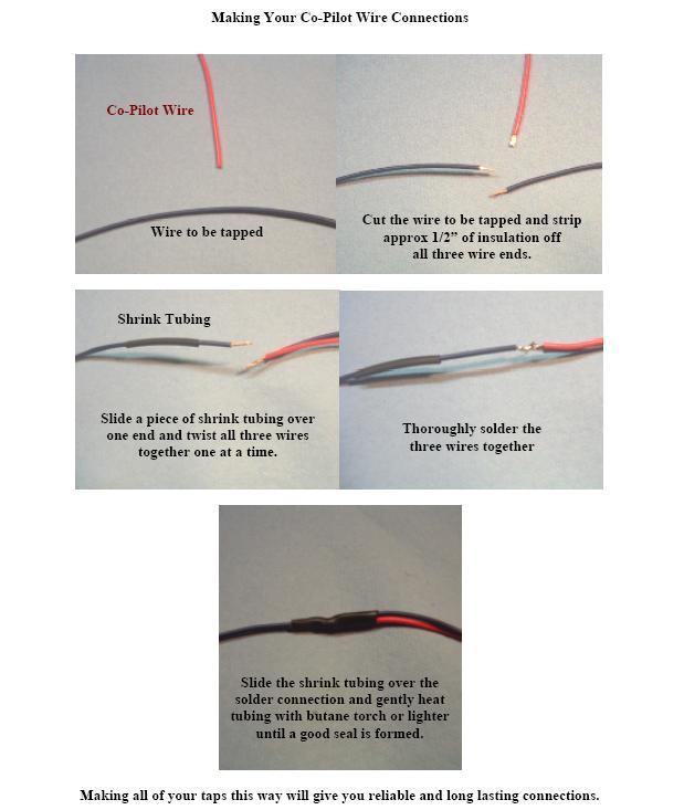
1 Installation Manual v1.6: Dodge 68RFE Automatic Transmission Please read all instructions before the installation of the ATS Co-Pilot Thank you for purchasing the ATS Co-Pilot transmission management computer. This manual is to assist you with your installation and operation of the unit. If you are installing the unit for a customer, please pass this manual on to your customer for future reference. Wiring Figure 1 - Kit Contents Disconnect the negative ground (black) terminals on all vehicle batteries before starting installation. The ATS 68RFE Co-Pilot is designed to be nearly completely plug-in; however, some tapped connections will be necessary. The following instructions will be divided up for wiring up each individual connector and wire color labeled on the ATS Co-Pilot. Solder all connections for
 to avoid damage to the wiring and harness.")
2 reliable results. These wire connections must be shielded from the elements (we recommend heat shrink tubing). NOTE: When routing the Co-Pilot harness, be sure to route the harness away from hot areas in the engine compartment (i.e. exhaust, turbo and EGR) to avoid damage to the wiring and harness. Reconnect all ground terminals on batteries after completing installation. Co-Pilot Mounting Location Find a convenient location to mount the Co-Pilot within reach and view of the driver. We recommend locating the unit just to the right of the driver on the lower dash panel (above the driver s right knee). Use the supplied Velcro to secure it to the dash. Before sticking the Velcro to the dash thoroughly clean the area with a cleaner such as acetone or brake clean (apply the cleaner to a clean rag or towel and wipe the area clean). Mount Co-Pilot in either of these positions Figure 2 - Suggested Co-Pilot Mounting Locations


3 Routing Co-Pilot Wiring Harness The Co-Pilot harness is designed to be simple and easy to route. Included in the kit, a large rubber grommet is designed to replace clutch master cylinder block-off plate located on the firewall. It is located on the driver s side of the firewall near the brake master cylinder. Inside the cab, the locations of the nuts are shown in Figure 3. Clutch Master Cylinder Bracket Figure 3 - Clutch Master Cylinder Bracket Location If not already done, push the 18-pin connector through the grommet supplied in the kit. Slide the 18-pin connector through the hole in the firewall from the engine side and mount the grommet in the hole. Make sure the pink wire is accessible inside the cab. TPS Wire Co-Pilot Harness Grommet in Firewall Figure 4 - Under Dash Components

4 Connect the 18-pin connector from the harness to the connector on the Co-Pilot control box and secure the box to the dash. In the opposite side of the harness, make sure the black and orange wires are accessible under the hood. The connections for these wires are covered later in this manual. Route the harness through the engine bay as shown below. Be sure to secure the harness away from major heat sources like the turbo(s) and exhaust manifold using the zip ties provided. Figure 5 - Co-Pilot Harness Routing The remainder of the harness is comprised of the connectors that will plug IN-LINE with the C4 (green) connector on the Powertrain Control Module (PCM). This portion is designed to plug into the factory harness to make installation of the Co-Pilot as simple as possible given the complexity of the wiring. The PCM is located on the passenger side of the firewall as shown in figures 6 and 7. The C4 connector is the connector location marked by green on the PCM. Remove this connector and plug the Co-Pilot harness into the PCM until the locking tab snaps over the ramp on the PCM. Connect the opposing connector in the Co-Pilot harness into the factory C4 connector (it will snap and lock into place).


5 Figure 6 - Powertrain Control Module and C4 Connector Locations (Passenger Side Firewall) Co-Pilot Harness into PCM PCM Behind Passenger Side Battery Co-Pilot Harness Factory Harness into Co-Pilot Harness Figure 7 - PCM Location and Connections

6 Secondary Control Box Mounting Location Mount the secondary control box (the black box with the 3-pin connector) in the driver side front wheel well just above the sway bar. The box is designed to use factory mounting locations. Located on the outside of the frame, a ground strap is bolted to the frame. Remove this bolt and install it through the hole as shown with the ground strap in place. Plug the 3-pin connector from the harness into the secondary control box. Chassis Ground Bolt 3-Pin Connector Figure 8 - Mounted Secondary Control Box -Black Wire- Chassis Ground - PIN #9 Connect the black wire to the negative (-) terminal of the battery.


7 -Pink Wire - Throttle Position Sensor (TPS) PIN #12 The pink wire is located in the Co-Pilot harness inside the cab. Locate the TPS connector at the top of the accelerator pedal arm under the dash. This is a six-pin connector. It is easiest if you unplug the connector and peel back some of the wire loom to access the wire. In PIN 2 of the terminal there is a brown with white stripe wire (the wire is mostly brown with a thin white stripe; do not confuse it with the white wire with brown stripe in pin 5). TAP this wire with the Co-Pilot s pink wire using the technique shown in the second to last page in this manual. Tap this wire TPS Connector Figure 9 - TPS/APPS Connector Location and WARNING: If tapped into any wire other than the Brown with White Stripe, the incorrect TPS signal will be sent to the Co-Pilot. This can cause serious transmission failure. DO NOT TAP the White with Brown Stripe wire located in pin 5. Please double check this connection before driving the vehicle. Figure 10 illustrates how to identify striped wires. Figure 10 - Striped Wire Clarification

8 -Orange Wire- Manifold Absolute Pressure (MAP) Sensor - PIN #4 Connect at the MAP sensor connector located on the driver s side of the engine, mounted on the backside of the intake manifold. The connector has four wires; TAP into the brown wire, which is in the number 1 terminal indicated on the connector. Use the technique shown in the second from last page of this manual for the tapped connection. MAP Sensor Connector Location Brown Wire Figure 11 - MAP Sensor Location and Pin-out IMPORTANT: If the vehicle has any aftermarket power modules installed, be sure to tap the MAP sensor wire BEFORE any taps from these power modules, i.e. place the Co- Pilot s tap closest to the sensor. The Co-Pilot may not work properly if it receives signals that have been modified by other aftermarket devices. The Co-Pilot does not modify the signal and will not interfere with any other devices that are connected down-stream or after the tapped Co-Pilot wire. Understanding this is extremely important because some aftermarket electronic modules change or cap the MAP signal sent to the computer. If the Co-Pilot wire is tapped between one of these modules and the truck s computer, it will not operate correctly and cause driveability problems. PCM Quick Learn Once installation is complete and BEFORE the truck is driven, you must do a quick learn on the transmission PCM. This can be done at any Chrysler dealer or most transmission service centers.

9 Understanding the operation of the ATS Co-Pilot The ATS Co-Pilot improves shift quality, determining and commanding optimum line pressure and internal clutch timing within the transmission to improve the reliability of the 68RFE 6-speed transmission. Mode Selection The front panel of the ATS Co-Pilot has 3 buttons and a series of LED indicators as shown below. The ATS Co-Pilot has 4 driving settings; Towing mod and 3 performance modes. To change these settings, press any button on the front panel of the display. The mode is indicated by the position of the purple lights on the front panel. To change the driving mode, simply use the UP and DOWN arrow keys on the front panel to change modes. This can be done while driving. The main difference between Towing mode and the Performance modes is torque converter clutch engagement. Towing mode engages the torque converter on deceleration to assist in braking. The performance modes employ more aggressive and firmer shifts. When the Co-Pilot is driven in the performance modes, shift quality is based on engine torque output, boost and throttle position.

10 Towing Mode 1 (Down arrow button, purple light to far right) The stock mode of the Co-Pilot uses optimized line pressures and factory lockup timing to improve drivability, reduce transmission temperatures and drastically improve the reliability of the transmission. This mode is best used with the factory exhaust brake and stock power levels. Performance Modes 2-4 (Purple light in right-center of display to far left of display) Performance modes 2-4 gradually change shift strategy and increase shift firmness. Mode 2 works well with light engine modifications while modes 3 and 4 work better for more heavily modified engines. Try each mode and see which best fits your driving style. Brightness Setting To change the brightness of the front panel, press the ATS button 2 times (all 4 purple lights will illuminate). Then use the UP and DOWN arrows to adjust brightness. Once selected, wait 4-5 seconds and the Co-Pilot will save the brightness setting. Boost Level Indication Once a drive setting is selected, the front display will revert to indicating boost pressure. The graduated scale is shown below. As long as the orange Co-Pilot wire is tapped into the MAP wire before any other aftermarket electronics as mentioned on page 8, the indicated boost level will be accurate.

11 Troubleshooting The ATS 68RFE Co-Pilot incorporates troubleshooting features for the transmission. If the Co-Pilot detects a problem within the transmission, it will flash certain purple lights on the front panel to indicate a problem. If the Co-Pilot flashes the purple lights while driving, refer to the diagram below to diagnose the issue. If the Co-Pilot detects any of these conditions, the Co-Pilot will force the pressure signal sent to the PCM to also set a corresponding diagnostic trouble code. This scheme allows isolation of pressure problems/connectivity issues between the Co-Pilot, transmission and PCM. IMPORTANT: Flashing lights on the Co-Pilot should be dealt with promptly. If line pressures are too low, serious transmission damage can occur.
12 If you experience problems after installation, simply unplug the wiring harness from the PCM and harness and reconnect the factory PCM connector.
13
14 Bill of Materials 1. Electronics Box Lockup Version code, 68RFE Co-Pilot Wiring Harness Lockup Version, 68RFE Co-Pilot Secondary Electronics Box Lockup Version, 68RFE Co-Pilot Hardware Pack Lockup Version, 68RFE Co-Pilot
12/05/2012 Lockup Co-Pilot Instructions INST. Installation Manual v1.6: Dodge 68RFE Automatic Transmission
 Installation Manual v1.6: 2007.5-09 Dodge 68RFE Automatic Transmission Please read all instructions before the installation of the ATS Co-Pilot Thank you for purchasing the ATS Co-Pilot transmission management
Installation Manual v1.0: Dodge 68RFE Automatic Transmission. Please read all instructions before the installation of the ATS Co-Pilot
 09/30/11 601-900-2356-INST Installation Manual v1.0: 2010-11 Dodge 68RFE Automatic Transmission Please read all instructions before the installation of the ATS Co-Pilot Thank you for purchasing the ATS
Installation Manual for Dodge 24V Cummins Version 3.1. Please read all instructions before the installation of the ATS Co-Pilot
 10/1/12 601-900-2218-INST Installation Manual for 1998.5-2002 Dodge 24V Cummins Version 3.1 Please read all instructions before the installation of the ATS Co-Pilot Thank you for purchasing the ATS Co-Pilot
Installation Manual v3.0: Dodge Cummins. Please read all instructions before the installation of the ATS Co-Pilot
 Installation Manual v3.0: 2004-2005 Dodge Cummins Please read all instructions before the installation of the ATS Co-Pilot Thank you for purchasing the ATS Co-Pilot Torque converter/exhaust brake controller.
Installation Manual for Dodge 12V Cummins Version 3.7. Please read all instructions before the installation of the ATS Co-Pilot
 Installation Manual for 1994-1998 Dodge 12V Cummins Version 3.7 Please read all instructions before the installation of the ATS Co-Pilot Thank you for purchasing the ATS Co-Pilot. This manual is to assist
GM ALLISON 6 SPEED LCT-1000/2000/2400 CO-PILOT Parts list
 2006-10 GM ALLISON 6 SPEED LCT-1000/2000/2400 CO-PILOT Parts list Co-Pilot Computer (1) 601-800-4308 Solenoid Block (1) 601-109-4308 External Wiring Harness (1) 601-011-4308 Internal Wiring Harness (1)
ATS Diesel Performance INST. Installation Manual for 2003 Dodge Cummins Version 3.1
 Installation Manual for 2003 Dodge Cummins Version 3.1 Please read all instructions before the installation of the ATS Co-Pilot Module Thank you for purchasing the ATS Co-Pilot Module Torque converter/exhaust
WARNING!!! DO NOT OPERATE WHILE DRVING!! INSTALLATION & USER GUIDE
 V-FORCE Plus Engineered For Power! WARNING!!! DO NOT OPERATE WHILE DRVING!! INSTALLATION & USER GUIDE Installation Instructions JET V-Force 1. Mounting the V-Force Using the supplied Velcro, Suction Cups
Allison Lockup Controller
 19 February 2018 1031311/1031312/1031313 Allison Transmission Lockup and Pressure Module (I-00413) 1 Allison Lockup Controller Transmission Lockup and Pressure Controller 1031311 1031312 1031313 2001-2010
Installation Manual for Ford Power Stroke Version 1.4. Please read all instructions before the installation of the ATS Co-Pilot Module
 6/12/08 COPLT-F-99-02-INST Installation Manual for 1999-2003 Ford Power Stroke Version 1.4 Please read all instructions before the installation of the ATS Co-Pilot Module Thank you for purchasing the ATS
High Idle Kit Dodge Cummins (24 valve) Dodge Cummins (with APPS on motor) PLEASE READ ALL INSTRUCTIONS BEFORE INSTALLATION
 Dodge Cummins (with APPS on motor) PLEASE READ ALL INSTRUCTIONS BEFORE INSTALLATION") U 6 May 2014 (1036620-27) 1998.5-2014 Dodge / GMC High Idle Kit (I-00321) 1 High Idle Kit 1036620 1998.5 2002 Dodge Cummins (24 valve) 2003-2004 Dodge Cummins (with APPS on motor) 1036621 2005-2006 Dodge
U 6 May 2014 (1036620-27) 1998.5-2014 Dodge / GMC High Idle Kit (I-00321) 1 High Idle Kit 1036620 1998.5 2002 Dodge Cummins (24 valve) 2003-2004 Dodge Cummins (with APPS on motor) 1036621 2005-2006 Dodge
Banks SmartLock. with installation instructions Ford 7.3L Power Stroke Turbo-Diesel Pickups
 owners manual with installation instructions Banks SmartLock trans brake 1994-2003 Ford 7.3L Power Stroke Turbo-Diesel Pickups THIS MANUAL IS FOR USE WITH SYSTEM 55255 & 55266 Gale Banks Engineering 546
V-FORCE Plus. Engineered For Power! WARNING!!! DO NOT OPERATE WHILE DRVING!! INSTALLATION & USER GUIDE First: Follow the Installation Guide
 V-FORCE Plus Engineered For Power! WARNING!!! DO NOT OPERATE WHILE DRVING!! INSTALLATION & USER GUIDE First: Follow the Installation Guide Card provided or Visit our Site for Wiring Charts 2015 JET Performance
WOT Box Installation Instructions VW / Audi
 Connector Pinout Pin Color AWG Name WOT Box Installation Instructions VW / Audi Description 1 Yellow 18 RPM Connect to Fuel Injector Drive Signal or Ignition Control Signal (varies by car model) 2 Black
DirectMount EXHAUST BRAKES
 DirectMount EXHAUST BRAKES APPLICATION: Fixed Orifice and PRXB Exhaust Brakes 2003 2005 Dodge Trucks with 3.5" & 4" Exhaust and 47RE & 48RE Automatic Transmissions Only Vehicles with an existing air compressor
V-Force USER GUIDE #67001/# JET Performance Products Apex Circle Huntington Beach, CA (714) Fax: (714) VF001 1/06
 Fax: (714) VF001 1/06") V-Force ACURA/HONDA USER GUIDE #67001/#67002 www.jetchip.com JET Performance Products 17491 Apex Circle Huntington Beach, CA 92647 (714) 848-5515 Fax: (714) 847-6290 VF001 1/06 2006 JET Performance Products
V-Force ACURA/HONDA USER GUIDE #67001/#67002 www.jetchip.com JET Performance Products 17491 Apex Circle Huntington Beach, CA 92647 (714) 848-5515 Fax: (714) 847-6290 VF001 1/06 2006 JET Performance Products
Installation Manual for Dodge Cummins Version 1.2. Please read all instructions before the installation of the ATS Co-Pilot Module
 COPLT-D-98.5-02-INST Installation Manual for 1998.5-2002 Dodge Cummins Version 1.2 Please read all instructions before the installation of the ATS Co-Pilot Module Thank you for purchasing the ATS Co-Pilot
Table of Contents. 4 Getting Started 4 About the Juice 5 Safety Terms 5 Product Registration 6 Important Notes 7 Truck Orientation
 Table of Contents 4 Getting Started 4 About the Juice 5 Safety Terms 5 Product Registration 6 Important Notes 7 Truck Orientation 8 Juice Installation 1999-2003 (7.3L) 8 Supplied Items & Required Tools
GM ALLISON 5 SPEED LCT-1000/2000/2400 CO-PILOT PARTS LIST
 2001-2005 GM ALLISON 5 SPEED LCT-1000/2000/2400 CO-PILOT PARTS LIST Co-Pilot Computer (1) 601-800-4248 Solenoid Block (1) 601-109-4248C External Wiring Harness (1) 601-011-4248 Internal Wiring Harness
Depress each tab as you pull the bezel off. The bezels are tight. L.H. shown.
 2013-2014 Ford Mustang V6 & Boss 302 Lower Valance Fog Light Kit Parts List: Quantity: Tool List: Fog light & bulb with bracket 2 Flat head & Phillips screwdriver Black bezels 2 Ratchet & Socket set OR
Banks SmartLock. THIS MANUAL IS FOR USE WITH system 55270
 owner s manual with installation instructions Banks SmartLock 2003-Early 2004 Dodge 5.9L CUMMINS TURBO DIESEL TRUCKS THIS MANUAL IS FOR USE WITH system 55270 Gale Banks Engineering 546 Duggan Avenue Azusa,
PRXB EXHAUST BRAKE MAXIMUM EXHAUST FLOW DESIGN
 MAXIMUM EXHAUST FLOW DESIGN PRXB EXHAUST BRAKE C44072/C44073/C44074/C44075/C44076 APPLICATION: 994-2002 DODGE RAM TRUCKS W/5.9L CUMMINS DIESEL ENGINES WITH MANUAL & AUTOMATIC TRANSMISSIONS STOCK DODGE
C FORD F250 / F L POWERSTROKE DIESEL WITH AUTOMATIC TRANSMISSIONS ONLY
 EXHAUST BRAKES C40019 1999-2003 FORD F250 / F350 7.3L POWERSTROKE DIESEL WITH AUTOMATIC TRANSMISSIONS ONLY Getting Started Thank you and congratulations on your purchase of a Pacbrake exhaust retarder.
Torque Convertor Control System
 22 September 2015 PN#1030395 TorqLoc (I-00208) 1 BD TorqLoc Torque Convertor Control System Part# 1030395 Installation Manual for the following applications: BD Brakes for Dodge, Ford and Chevrolet Pac
Installation Manual for VMAC Throttle Commander Throttle Control T500111
 Installation Manual for VMAC Throttle Commander Throttle Control T500111 2006-2007 Classic GMC CK2500-3500 6.0L Gasoline Engines 1.0 Preparation for Installation...4 1.1 Automatic Transmission Trucks...4
Installation Manual v1.0: Twin CP3 Fuel Injection Kit Dodge 6.7L
 04/05/2012 Dodge 2010-2011 6.7L Twin CP3 701-900-2356-INST Installation Manual v1.0: Twin CP3 Fuel Injection Kit 2010-2011 Dodge 6.7L Figure 1 - Full Kit Photo 29 Figure 2 - Hardware Kit (800) 949-60002
Table Of Contents TABLE OF CONTENTS INTRODUCTION INSTALLATION OPERATING INSTRUCTIONS APPENDIX ABOUT THE JUICE... 3 SAFETY TERMS...3 INTRODUCTION...
 Ford Juice installation Instructions **read important safety information in this manual** TABLE OF CONTENTS F o r d J u i c e Table Of Contents ABOUT THE JUICE... 3 SAFETY TERMS...3 INTRODUCTION... 3 PRODUCT
PRXB EXHAUST BRAKE HIGH PERFORMANCE
 HIGH PERFORMANCE PRXB EXHAUST BRAKE C44059, C4406, C44063, C44065 APPLICATION 994-2002 DODGE RAM AUTOMATIC TRUCKS EQUIPPED WITH 47RE TRANSMISSIONS WITH 5.9L, 24 VALVE CUMMINS DIESEL ENGINES GETTING STARTED
Guardian Personal Mobility Lift Interlock GRD701-AR ( Dodge Sprinter) Installation Instructions
 Installation Instructions") An ISO 9001:2000 Registered Company Guardian Personal Mobility Lift Interlock GRD701-AR (2007-2008 Dodge Sprinter) Installation Instructions GUARDIAN MODULE Remove drivers seat and step-well trim for access.
An ISO 9001:2000 Registered Company Guardian Personal Mobility Lift Interlock GRD701-AR (2007-2008 Dodge Sprinter) Installation Instructions GUARDIAN MODULE Remove drivers seat and step-well trim for access.
Installation Manual for VMAC Throttle Commander Throttle Control T500100
 Installation Manual for VMAC Throttle Commander Throttle Control T500100 2003-2005 Chevrolet Tahoe, GMC Yukon, CK2500HD-3500 4.8L, 5.3L, 6.0L and 8.1L Gasoline Engines 1.0 Preparation for Installation...
Ford Racing 4.6L 3V Crate Engine Control Pack
 Ford Racing 4.6L 3V Crate Engine Control Pack Installation Time: 3-6 hours on a Foxbody Mustang Tools Required: Basic English and Metric Socket and Wrench Set Flat and Phillips Screwdrivers Torx bits Hammer
The ignition coil for the vehicles covered by this guide is in the following locations:
 Dakota Trucks 1989-1996 Ignition Tests COIL The ignition coil for the vehicles covered by this guide is in the following locations: 1989-92 engines: mounted to the firewall 1993-96 2.5L engines: mounted
ELECTRONIC POSITIVE AIR SHUTOFF
 12 January 2015 103675X Electronic positive air shutdown (I-00336) 1 ELECTRONIC POSITIVE AIR SHUTOFF 1036750 2007-2009 Dodge 6.7L 1036751 2010-2015 Dodge 6.7L 1036754 2008-2010 Ford 6.4L 1036755 2011-2014
U L T I M A T E R A D A R / L A S E R D E F E N S E S Y S T E M
 S m a r t e r Q u i e t e r M o r e A c c u r a t e U L T I M A T E R A D A R / L A S E R D E F E N S E S Y S T E M Installation Manual PASSPORT 9500ci Comes Complete Front Radar Receiver Miniature weatherproof
Throttle Sensitivity Booster
 U 1 New version allows for optional control switch. See page 4 for details. Throttle Sensitivity Booster Apps Booster 1057730 (Manual trans only) Vehicle / Year 1998.5-2003 Dodge Cummins DO NOT INSTALL
advanced FLOW engineering Instruction Manual P/N:
 advanced FLOW engineering Instruction Manual P/N: 77-84010 Make: Chevrolet Model: Silverado HD Year: 2017-2018 Engine: V8-6.6L (td) Duramax (L5P) Make: GMC Model: Sierra HD Year: 2017-2018 Engine: V8-6.6L
Torque Convertor Control System
 1 BD AutoLoc Torque Convertor Control System Part# 1030390 Installation Manual for the following applications: BD Brakes for Dodge, Ford and Chevrolet Pac Brake for Dodge & Ford Jacobs E-Brake for 1994-98
Ford 6.7 EGR Delete Kit
 Fits: 2011 12 Powerstroke 6.7L Read instructions thoroughly before proceeding! ***This kit may void factory warranty please check with manufacturer.*** ***This kit is intended for off road use only.***
owners manual Banks Brake with installation instructions Exhaust BrakE system Dodge IsB 5.9L Cummins (24-valve) turbo-diesel Pickups
 turbo-diesel Pickups") owners manual with installation instructions Banks Brake Exhaust BrakE system 1998-2002 Dodge IsB 5.9L Cummins (24-valve) turbo-diesel Pickups THIS MANUAL IS FOR USE WITH SYSTEM 55219 & 55221 2010 gale
owners manual with installation instructions Banks Brake Exhaust BrakE system 1998-2002 Dodge IsB 5.9L Cummins (24-valve) turbo-diesel Pickups THIS MANUAL IS FOR USE WITH SYSTEM 55219 & 55221 2010 gale
TELORVEK EFI 5.0 Coyote Sequential Fuel Injection System Part # CY-11
 Page #1 TELORVEK EFI 5.0 Coyote Sequential Fuel Injection System Part # CY-11 WIRING INSTRUCTIONS Thank you for purchasing the absolute finest of wiring kits for the Ford Motor Co. Coyote modular engine.
Dodge Ram 09-Current CS-DTR SERIES BACKUP CAMERA INSTALLATION
 Dodge Ram 09-Current CS-DTR SERIES BACKUP CAMERA INSTALLATION Thank you for your purchase! These instructions cannot possibly cover every option group for every model year of RAM trucks so you may find
Congratulations on purchasing the Edge Juice/Attitude system for the Dodge Cummins Diesel.
 Getting Started About the Juice Congratulations on purchasing the Edge Juice/Attitude system for the Dodge Cummins Diesel. The Juice/Attitude system features an intelligent module (Juice) that acts as
DODGE SRT-4 PART NUMBER P (with Turbo Toys) P (without Turbo Toys) P (Stage 2 to Stage 3R Upgrade Kit)
 P (without Turbo Toys) P (Stage 2 to Stage 3R Upgrade Kit)") INFORMATION SHEET Stage 3R Turbo Upgrade Kit Components (1) Stage 3R PCM (4) 682 cc/min Fuel Injectors* (1) 3.0 bar MAP Sensor* (1) 3.0 bar TIP Sensor* (1) Block-off Connector for PCM (1) Mopar TD05HR
INFORMATION SHEET Stage 3R Turbo Upgrade Kit Components (1) Stage 3R PCM (4) 682 cc/min Fuel Injectors* (1) 3.0 bar MAP Sensor* (1) 3.0 bar TIP Sensor* (1) Block-off Connector for PCM (1) Mopar TD05HR
Dodge Cummins Positive Air Shutoff
 1998-2002 24V 5.9 Dodge Cummins Positive Air Shutoff (I-00181) 1 INSTALL MANUAL 1998.5-2002 5.9 Dodge Cummins Positive Air Shutoff P/N# 1036719 P/N# 1036719-M UPLEASE READ ALL INSTRUCTIONS BEFORE INSTALLATION
Installation Manual v2.2: Twin CP3 Fuel Injection Kit Dodge 5.9L
 12/13/11 ATS Twin CP3 Kit 701-900-2272-INST Installation Manual v2.2: Twin CP3 Fuel Injection Kit 2003-2004 Dodge 5.9L Figure 1 - Full Kit Photo 26 Figure 2 - Hardware Kit 1 Please read all instructions
Installation Manual v2.5: Dodge 1994 to 2005 Ford 1994 to 2002-½ For Full Lock-Up And/Or Exhaust Brake Control
 Installation Manual v2.5: Dodge 1994 to 2005 Ford 1994 to 2002-½ For Full Lock-Up And/Or Exhaust Brake Control Please read all instructions before the installation of the ATS Commander Module Thank you
2004½-07 Dodge Cummins BD Turbo Mount Exhaust Brake Installation Instructions
 1 2004½-07 Dodge Cummins BD Turbo Mount Exhaust Brake Installation Instructions BD P/N# Application 2023331 2004½-2005 Dodge Cummins 2023330 2006-2007 Dodge Cummins Serial # Date Purchased Installed by
Installation Instructions General Motors 8.1 Sequential Vapor Injection (S.V.I.) System 7500/6500 Series Trucks model year.
 System 7500/6500 Series Trucks model year.") Installation Instructions General Motors 8.1 Sequential Vapor Injection (S.V.I.) System 7500/6500 Series Trucks 2003-2005 model year. Technocarb Equipment (2004) Ltd. 4-30435 Progressive Way Abbotsford,
Installation Instructions General Motors 8.1 Sequential Vapor Injection (S.V.I.) System 7500/6500 Series Trucks 2003-2005 model year. Technocarb Equipment (2004) Ltd. 4-30435 Progressive Way Abbotsford,
Contents. TCS/ Driver Mod Installation Manual
 Contents Introduction... 1 TCS Packing List... 3 Tools Needed for Installation... 4 How to Properly Solder... 5 Soldering Standard Butt Connection... 5 Soldering T Connection... 6 How to Properly Crimp...
Installation Manual v1.0: Twin CP3 Fuel Injection Kit Dodge 5.9L
 Installation Manual v1.0: Twin CP3 Fuel Injection Kit 2004.5-2007 Dodge 5.9L Figure 1 - Full Kit Photo 25 Figure 2 - Hardware Kit Please read all instructions before installation. This kit is not emissions
with installation boost GAUGE this manual is for use with systems
 owners manual with installation instructions dynafact boost GAUGE this manual is for use with systems 64050-64054 gale banks engineering 546 duggan avenue azusa, ca 91702 (626) 969-9600 www.bankspower.com
Installing the Throttle Commander Ford F250 F550 Super Duty T L Diesel T L Diesel
 Installing the Commander Ford F250 F550 Super Duty T500106 2005-2007 6.0L Diesel T500116 2008-2010 6.4L Diesel 1.0 Preparing for Installation...5 2.0 Installing the Control...5 2.1 2005-2007 T500106 Connecting
advanced FLOW engineering Instruction Manual P/N: SCORCHER BLUE Bluetooth Power Module
 advanced FLOW engineering Instruction Manual P/N: 77-84009 SCORCHER BLUE Bluetooth Power Module Make: Chevrolet Model: Colorado Year: 2016-2019 Engine: I4-2.8L (td) Duramax (LWN) Make: GMC Model: Canyon
advanced FLOW engineering Instruction Manual P/N: Make: Ford Model: F-150 Raptor Year: Engine: V6-3.
 advanced FLOW engineering Instruction Manual P/N: 77-83023 Make: Ford Model: F-150 Raptor Year: 2017-2018 Engine: V6-3.5L (tt) EcoBoost Please read the entire instruction manual before proceeding. Ensure
2001 Honda Civic EX ACCESSORIES & EQUIPMENT' 'Cruise Control Systems - Civic & CR-V 2001 ACCESSORIES & EQUIPMENT
 DESCRIPTION 2001 ACCESSORIES & EQUIPMENT Cruise Control Systems - Civic & CR-V Cruise control system uses mechanical and electrically operated devices to maintain vehicle speed settings greater than 25
GENESIS Electronic Brake Controller Hayes Brake Controller Company - P/N 81790
 GENESIS Electronic Brake Controller Hayes Brake Controller Company - P/N 81790 INSTALLATION MANUAL For trailers with 2-8 electric brakes and vehicles with 12 volt negative ground systems only. READ AND
INSTALLATION MANUAL AP60B INSTALLATION MANUAL
 INSTALLATION MANUAL 2. TOOLS REQUIRED The following is a list of tools required to properly install the cruise control. While this unit may be installed without some of the tools listed, it is recommended
INSTALLATION INSTRUCTIONS
 OEM Recessed Lip Camera with Harness and OnStar Mirror for GM Vehicles with 10-pin Mirror Connector (Kit part number 9002-8722) Please read thoroughly before starting installation and check that kit contents
C40008 & C40009 EXHAUST BRAKES
 EXHAUST BRAKES C40008 & C40009 1995 2003 Ford F250 / F350 7.3 L Powerstroke Diesel with manual transmissions 1995 1998 Ford F250 / F350 7.3 L Powerstroke Diesel with automatic transmission* *Requires the
Installation Manual v1.0: Code Blocker Electronics Kit GM LBZ Duramax. Please read all instructions before installation.
 Installation Manual v1.0: Code Blocker Electronics Kit 2006-07 GM LBZ Duramax Please read all instructions before installation. 1. Mount the electronics package on the grill support as shown. Use the self-tapping
ACD-PRO Install in 2008 EvoX
 Turning in a counter clockwise direction, unscrew ift knob ACD-PRO Install in 2008 EvoX Slide back and remove the floor console panel assembly Pull up to remove the center console tray Disconnect the plug
INSTALLATION MANUAL
 315000 INSTALLATION MANUAL EGR & Cooler Race Kit for 2015+ 6.7L Ford Powerstroke WARNING ONLY install this kit if you are using a tuner that disables the EGR sensors & circuit system. Any product that
Installation Instructions For #63021 Striker Diesel MD Power Modules Dodge 600/610 Cummins 5.9L Diesel Copyright
 2501 Ludelle Street Fort Worth, Texas 76105 817-244-6212 Phone 817-244-4024 Fax 888-350-6588 Sales 800-423-9696 Tech E-mail: painless@painlessperformance.com Web: www.painlessperformance.com Installation
Copyright TST Products, Inc
 Installation and Operating Instructions TST POWERMAXCR for 03-06 Ram/Cummins Engine For the PMCR R37AP skip the steps regarding the thermocouple and rail pressure sensor. Make sure the red and yellow wires
INSTALLATION MANUAL. Middle. Def tank. Standard. Middle. Standard. Def tank WARNING. Level of Difficulty CAUTION. Parts List.
 INSTALLATION MANUAL 3025101 Level of Difficulty Moderate This is the second first of two of two manuals required to complete this installation. The first second manual manual is is included with with your
Generation III Stand Alone Engine Harness
 78 Rattler Curry Road, Columbia, KY 42728 Phone 1-888-467-4491 sales@bp-automotive.com www.bp-automotive.com Generation III Stand Alone Engine Harness Installation Guide At BP Automotive we take pride
Optimized Idle Aftermarket Installation Kits On-Highway Truck Applications (P/N: )
") 18SP655 Optimized Idle Aftermarket Installation Kits On-Highway Truck Applications (P/N: 23538534) KIT DESCRIPTION The Optimized Idle Aftermarket Installation Kit provides the components necessary for
18SP655 Optimized Idle Aftermarket Installation Kits On-Highway Truck Applications (P/N: 23538534) KIT DESCRIPTION The Optimized Idle Aftermarket Installation Kit provides the components necessary for
CRUISE CONTROL SYSTEM
 CRUISE CONTROL SYSTEM 1998 Pontiac Bonneville 1998 ACCESSORIES & EQUIPMENT General Motors Corp. - Cruise Control System Buick; LeSabre Oldsmobile; Eighty Eight, LSS & Regency Pontiac; Bonneville * PLEASE
Installation Instructions
 This product has been designed and manufactured to work correctly with installation as described in these instructions. Failure to follow these instructions could result in damage to property, damage to
Installation Items: Cruise Module
 Installation Items: Rostra 250-1223, Electronic Cruise Control System (ECCS) includes the cruise module, harness, cruise cable, cruise module mounting bracket, cruise cable mounting bracket and hardware
BD PRESSURELOC INSTALLATION MANUAL
 May 03 BD PressureLoc #1030377 1 BD PRESSURELOC INSTALLATION MANUAL READ ALL INSTRUCTIONS BEFORE INSTALLATION May 03 BD PressureLoc #1030377 2 KIT COMPONENTS Switched 12V wiring harness Control Valve Attachments
Installation Instructions #63000 Striker Diesel MD Power Module Chevrolet Duramax 6.6L Diesel
 2501 Ludelle Street Fort Worth, Texas 76105 817-244-6212 Phone 817-244-4024 Fax 888-350-6588 Sales 800-423-9696 Tech E-mail: painless@painlessperformance.com Web: www.painlessperformance.com Installation
Getting Started. About the Juice. Congratulations on purchasing the Edge Juice/Attitude system for the Dodge Cummins Diesel.
 Getting Started About the Juice Congratulations on purchasing the Edge Juice/Attitude system for the Dodge Cummins Diesel. The Juice/Attitude system features an intelligent module (Juice) that acts as
PLEASE READ ALL DIRECTIONS BEFORE STARTING INSTALLATION
 PARTS LIST 2006-2014 Suzuki M109R / C109R Installation Instructions 1 Power Commander 1 USB Cable 1 Installation Guide 2 Power Commander Decals 2 Dynojet Decals 2 Velcro strips 1 Alcohol swab 1 Zip tie
FORD E4OD/4R100 AUTOMATIC TRANSMISSION EQUIPPED VEHICLES
 owners manual with installation instructions TransCommand FORD E4OD/4R100 AUTOMATIC TRANSMISSION EQUIPPED VEHICLES THIS MANUAL IS FOR USE WITH SySTEM 62560 & 62570 also available from banks Power for 94-03
INSTALLATION INSTRUCTIONS
 OEM Lip Mount Camera with Harness and OnStar Mirror for GM Vehicles with 10-pin Mirror Connector (Kit part number 9002-8723) Items Included in the Kit: Bubble bag containing: Camera with Mount Mirror Mirror
Throttle Sensitivity Booster
 U 21 March 2018 1057730-1057737 Throttle Sensitivity Booster (I-00358) 1 DOWNLOAD COLOR INSTALL MANUALS AT dieselperformance.com New version allows for optional control switch. See page 4 for details.
8436, 8437, 8438, 8439, 8442, 27480, 27780, 28028, & ISOLATION MODULE ELECTRICAL SYSTEM
 September 11, 2003 Lit. No. 27808 8436, 8437, 8438, 8439, 8442, 27480, 27780, 28028, & 28400 ISOLATION MODULE ELECTRICAL SYSTEM Installation Instructions Read this document before installing the snowplow.
OEM Lip Mount Camera with Harness and OnStar Mirror for GM Vehicles with 16-pin Mirror Connector (Kit part number )
") OEM Lip Mount Camera with Harness and OnStar Mirror for GM Vehicles with 16-pin Mirror Connector (Kit part number 9002-8722) Please read thoroughly before starting installation and check that kit contents
OEM Lip Mount Camera with Harness and OnStar Mirror for GM Vehicles with 16-pin Mirror Connector (Kit part number 9002-8722) Please read thoroughly before starting installation and check that kit contents
Remove black panel shown. Save 6 retaining pins for re-install later. Pry up on center part of pin first. Then pry out entire retaining pin.
 2005-2009 Ford Mustang V6 Fog Light Wiring Kit Parts List: Quantity: Tools Required: Wiring harness 1 Flat head screwdriver Supplemental wire leads 2 Ratchet & Socket set OR Wire tap red 2 Adjustable Wrench
2004½-07 Dodge Cummins Turbo Mount BD Exhaust Brake Installation Instructions
 1 2004½-07 Dodge Cummins Turbo Mount BD Exhaust Brake Installation Instructions BD P/N Application 2023331 2004½-2005 Dodge Cummins 2023330 2006-2007 Dodge Cummins Serial # Date Purchased Installed by
Allison Lockup Controller
 Allison Lockup Controller Installation instructions (2012-2014 LML) NOTE: THIS IS FOR 2012-2014 ONLY!!!!! By: BT DieselWorks, LLC. First of all, thank-you for purchasing the BT DieselWorks 2 nd generation
Dodge Cummins Positive Air Shutoff
 21 October 2011 2003-2007 5.9 Dodge Cummins Positive Air Shutoff 1 2003-2007 5.9 Dodge Cummins Positive Air Shutoff P/N# 1036720 P/N# 1036720-M UPLEASE READ ALL INSTRUCTIONS BEFORE INSTALLATION 21 October
INSTALLATION INSTRUCTIONS UNLEASH. THE SMARTEST PERFORMANCE TUNING TECHNOLOGY
 INSTALLATION INSTRUCTIONS R UNLEASH. THE SMARTEST PERFORMANCE TUNING TECHNOLOGY FUEL + QUICKSHIFT + TRACTION CONTROL MV AGUSTA F3 2013 BRUTALE 675 2013 T1641S, T1641R 1>READ WARNINGS > INSTALLING We strongly
2002 Chevrolet Silverado 1500
 For the specific DTCs required for each system, see table. Systems such as fuel delivery, misfire, and comprehensive components may not be listed in a system status list. These tests run continuously on
Dodge Cummins Positive Air Shutoff
 8 April 2013 2003-2007 5.9 Dodge Cummins Positive Air Shutoff 1 2003-2007 5.9 Dodge Cummins Positive Air Shutoff P/N# 1036720 P/N# 1036720-M UPLEASE READ ALL INSTRUCTIONS BEFORE INSTALLATION 8 April 2013
Direct Mount EXHAUST BRAKES
 Direct Mount EXHAUST BRAKES APPLICATIONS: Fixed Orifice & PRXB Exhaust Brakes 2003-2005 Dodge trucks with 3.5 & 4 exhaust and 47RE &48RE Automatic Transmissions only THIS KIT IS NOT FOR USE ON 2006 & 2007
PERFORMANCE SYSTEMS INTEGRATION
 2006 Current GEN IV LSX/Vortec 4.8, 5.3, 6.0, 6.2, 7.0 Drive by Wire (58X) Electronic Fuel Injection Wiring Harness w/ Manual or Non- Electronic Automatic Transmission HAR-10 (See Below) (P/N HAR- 1035,
Banks Six-Gun Diesel Tuner WITH OPTIONAL SPEED-LOADER MODULE (LB7) Chevy/GMC 6.6L Duramax Turbo-Diesel Pickups
 Chevy/GMC 6.6L Duramax Turbo-Diesel Pickups") with Installation Instructions Owner smanual Banks Six-Gun Diesel Tuner WITH OPTIONAL SPEED-LOADER MODULE 2001-2004 (LB7) Chevy/GMC 6.6L Duramax Turbo-Diesel Pickups THIS MANUAL IS FOR USE WITH SYSTEMS
with Installation Instructions Owner smanual Banks Six-Gun Diesel Tuner WITH OPTIONAL SPEED-LOADER MODULE 2001-2004 (LB7) Chevy/GMC 6.6L Duramax Turbo-Diesel Pickups THIS MANUAL IS FOR USE WITH SYSTEMS
GM TRUCK BACKUP CAMERA INSTALLATION
 GM TRUCK 07-13 BACKUP CAMERA INSTALLATION Thank you for your purchase! These instructions are intended for the do-it-yourselfer who decides to install the camera without professional assistance. Keep in
BMS S63TU Stage1 and JB4 Install Guide
 BMS S63TU Stage1 and JB4 Install Guide Last updated 3/23/2018 Use subject to terms and conditions posted at http://www.burgertuning.com/terms.htm THIS PART IS LEGAL FOR USE ONLY IN COMPETITION RACING VEHICLES
Pittsburgh Power Detroit DDEC-V Installation Instructions By: Pittsburgh Power
 Pittsburgh Power Detroit DDEC-V Installation Instructions By: Pittsburgh Power Congratulations on the purchase of your Pittsburgh Power performance computer system. The only product of it s kind! These
Dodge Cummins Positive Air Shutoff
 21 October 2011 1998-2002 24V 5.9 Dodge Cummins Positive Air Shutoff 1 1998.5-2002 5.9 Dodge Cummins Positive Air Shutoff P/N# 1036719 P/N# 1036719-M UPLEASE READ ALL INSTRUCTIONS BEFORE INSTALLATION 21
Installation Instructions JMS PedalMAX Kit P/N PX GM GM Drive-By-Wire Electronic Throttle Enhancement Device
 Installation Instructions JMS PedalMAX Kit P/N PX-5000-1415GM 2013-2015 GM Drive-By-Wire Electronic Throttle Enhancement Device Included in the PedalMAX kit: (1) PedalMAX assembly (1) 4-pin RED de-sensitizing
Dodge Cummins Positive Air Shutoff
 1 INSTALL MANUAL 2010-2012 6.7 Dodge Cummins Positive Air Shutoff P/N# 1036722 P/N# 1036722-M UPLEASE READ ALL INSTRUCTIONS BEFORE INSTALLATION An Information decal has been provided in this kit. This
Banks Brake. with installation instructions EXHAUST BRAKE SYSTEM Dodge 5.9L Cummins (12-valve) Turbo-Diesel Pickups with Manual Transmissions
 Turbo-Diesel Pickups with Manual Transmissions") OWNERS MANUAL with installation instructions Banks Brake EXHAUST BRAKE SYSTEM 1994-98 Dodge 5.9L Cummins (12-valve) Turbo-Diesel Pickups with Manual Transmissions THIS MANUAL IS FOR USE WITH SYSTEMS 55217
OWNERS MANUAL with installation instructions Banks Brake EXHAUST BRAKE SYSTEM 1994-98 Dodge 5.9L Cummins (12-valve) Turbo-Diesel Pickups with Manual Transmissions THIS MANUAL IS FOR USE WITH SYSTEMS 55217
Ford Mustang GT-Style Fog Light Kit Parts List: Quantity: Tool List:
 2013-2014 Ford Mustang GT-Style Fog Light Kit Parts List: Quantity: Tool List: Fog light (Left& Right) 2 Flat head & Phillips screwdriver Upper grille with surround 1 Ratchet & Socket set OR Lower grille
Dodge Cummins Positive Air Shutoff
 10 June 2013 1998-2002 24V 5.9 Dodge Cummins Positive Air Shutoff 1 1998.5-2002 5.9 Dodge Cummins Positive Air Shutoff P/N# 1036719 P/N# 1036719-M UPLEASE READ ALL INSTRUCTIONS BEFORE INSTALLATION 10 June
V8 Gen. V Ford Mustang 2010 Update
 V8 Gen. V Ford Mustang 2010 Update There were several updates to the Ford Mustang in the 2010 model year. This document outlines the differences between the installation steps necessary for the 2010 Mustang
90558 Installation Manual For # Cummins 5.9L Common Rail Diesel
 2501 Ludelle Street Fort Worth, Texas 76105 817-244-6212 Phone 817-244-4024 Fax 888-350-6588 Sales 800-423-9696 Tech E-mail: painless@painlessperformance.com Web: www.painlessperformance.com 90558 Installation