2010+ Camaro Triple-Threat Wet Nitrous System
|
|
|
- Leon Owens
- 6 years ago
- Views:
Transcription
 1. Remove power Disconnect negative battery cable from battery terminal; then do the same with the positive cable.")
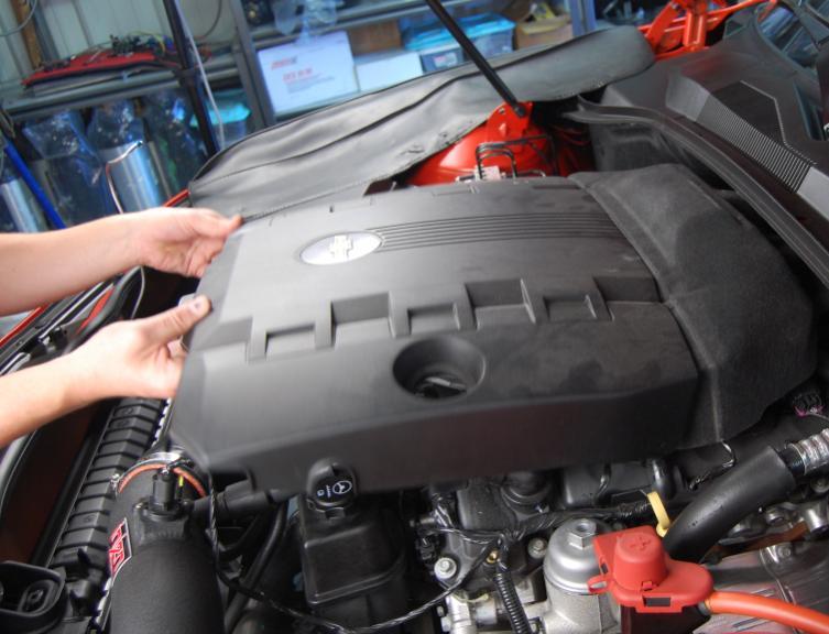
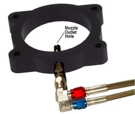
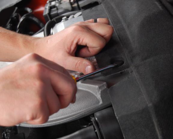
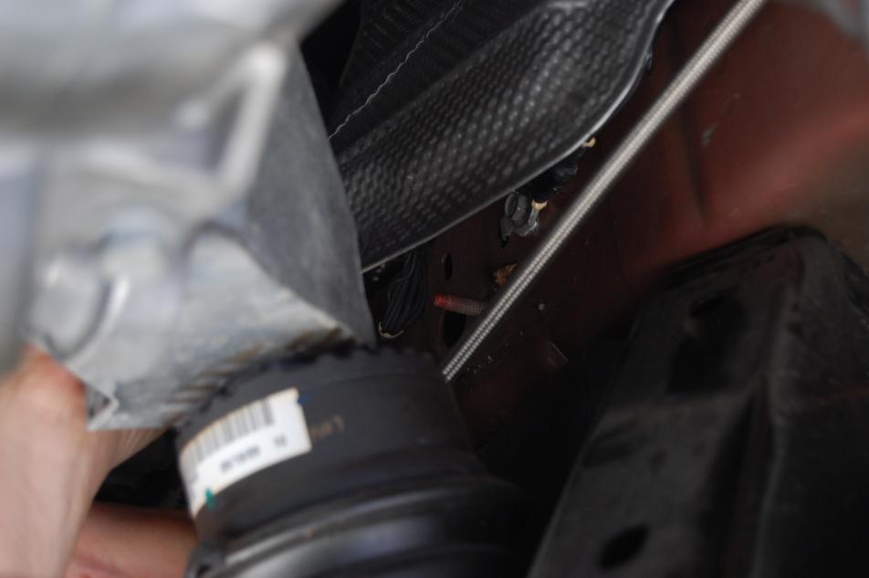
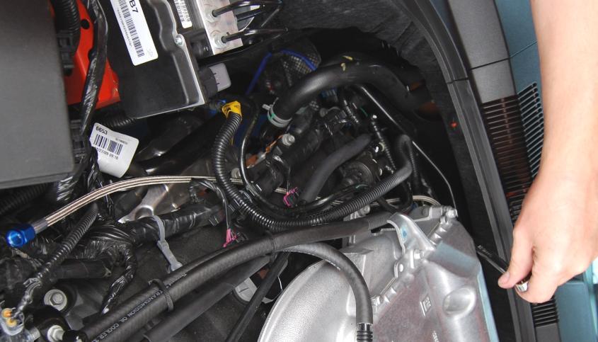
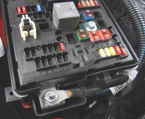
1 2010+ Camaro Triple-Threat Wet Nitrous System This Installation Guide is to be used with the Ny-Trex Owner s Manual. (Refer to the Owner s Manual for installation tips, safety tips, and precautions) 1. Remove power Disconnect negative battery cable from battery terminal; then do the same with the positive cable. Note: the battery is located in the trunk- where a spare tire would apparently reside. Next, disconnect the Engine Control Module (ECM) connectors located in the engine bay, on the passenger side, next to the fuse box (figure 1). 2. Remove Engine Cover Remove oil fill cap and lift front of plastic cover to remove. Unlock the clips to remove the soft cover (figures 2 & 3). 3. Assemble Throttle Body (TB) Plate, Nozzle assembly, and lines Assemble the throttle body plate (10), nozzle (11), jets (8), 90 nozzle adapters (16), and 12 nozzle lines (8). Insure nozzle outlet hole and lines are configured as shown in figure 4. Note: Only use thread sealer (19) on NPT fittings- never use on flare fittings! 4. Install TB Plate Assembly Remove air intake tube from throttle body (TB) and air box. Disconnect TB wire harness and loosen/remove TB bolts. Remove and discard OEM TB gasket. Using longer TB bolts/washers (18) and gaskets (17), attach Ny-Trex TB plate assembly to intake manifold- braided lines should go toward passenger s side. Note: two new gaskets should be placed on either side of TB plate on vehicles; only require one gasket on TB side of plate. Re-connect wire harness and re-assemble air intake tube. 5. Mount Camaro Triple-Threat Assembly Loosen and remove bolt which retains water pipe on passenger s side cylinder head (figure 5). Install the Triple-Threat assembly on top of this pipe bracket with OEM bolt (figure 6). Connect the nozzle lines to the appropriate fittings on the Triple- Threat valve. Note: the red fuel line connects to the rear fitting, and the blue nitrous line to the middle fitting (figures 7 & 8). 6. Connect Fuel Supply Line Remove the service cap from the fuel pressure Schrader valve at back of engine near the firewall (figure 9). Place a shop rag around the valve fitting to catch and contain escaping fuel. SLOWLY start to remove the Schrader valve, letting the fuel that is still under pressure seep out and soak into the rag. This will depressurize the fuel system. When the system is depressurized, completely remove the valve. Retain and store the valve for future reinstallation. Install the 90 fuel supply adapter (15) with the outlet clocked toward the passenger side front wheel (figure 10). Connect the fuel supply line (6) to the adapter and route the line over the valve cover to the Triple-Threat valve (figure 11). Connect the loose end of the line to the blue rear-facing fitting on the Triple-Threat valve. Tighten both ends of line.
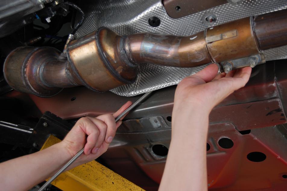
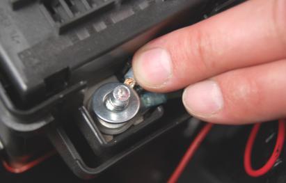
2 7. Install Engine Bay Electrical System Remove fuse box cover, located in engine bay just behind passenger side headlight. Remove the nut on the positive terminal, located immediately in front of the fuse box (figure 12). Install the eyelet connectors from the Triple-Threat valve harness to the terminal and reinstall the nut (figure 13). Connect and install the engine to passenger bay extension cable (5). It should be routed from the fuse box vicinity to the firewall, following the wire harness that passes over the passenger side strut tower. Unlock the plastic cowl cover clips and lift the cover (figure 14). Route the wire to the driver side of the car in the cowl channel. Exit cowl and pull wire through the firewall utilizing one of the available grommets under the brake booster, providing access to the driver s foot area. Fasten all loose wire with zip ties (9). 8. Install Passenger Compartment Electrical System Locate and remove the bottom-right bolt on the accelerator pedal assembly and place the WOT bracket/switch over the revealed hole. Insert the bolt into the wire eyelet on the supplied passenger bay harness (4). Then insert the bolt into the bracket and pedal assembly (figure 15). Adjust bracket/switch assembly down and to the right (figure 16); tighten bolt assuring its proper orientation. Test for proper operation and adjust if necessary. Route the remaining wiring and components toward the location at which the activation and purge button will be installed. Note: improper installation may result in faulty activation. 9. Install the Purge Button and Activation Switch Location of these controls is determined by owner/installer preference. Any location within easy reach of the driver is acceptable. Note: many Ny-Trex customers fabricate a small switch panel which can be placed in the cup-holder/ash tray compartment. After switches have been installed, connect the remaining two connectors from the passenger bay electrical components to the extension cable. Hide and tie all access/loose wire under the dash utilizing zip ties (9). 10. Install Purge Components Locate a preferred point at which the v-spray purge block should be mounted. Note: the aluminum tubing (7) is 3 feet long, so choose a location accordingly. Connect the aluminum line to the v-spray purge block utilizing the brass compression fitting. Thread sealer (19) may be used on the brass fitting to purge block connection. Mount the purge block. Route the aluminum tubing to the fitting labeled PURGE OUT, on the Triple-Threat valve. Connect to fitting and tighten. See figures for examples of a suitable and stylish location. 11. Initialize Nitrous Supply Line Routing Refer to page 10 of the Owner s Manual for details, tips, and precautions. Lift the trunk compartment carpeting on the right side and fold to the left, exposing trunk pan (figure 21). Remove black plastic plug and feed line through the hole (figure 22). The line will exit just above muffler. Pull majority of line through the pan. 12. Mount the Nitrous Bottle Note: carefully consider the carpeting and what the owner/installer prefers while progressing through the steps to install the bottle. Mounting the bottle on top of the carpeting will require drilling and or cutting, while leaving the carpeting folded back requires none. Mount the bottle brackets (2) to bottle (1) as described on page 10 of the Owner s Manual. Place the bottle on the trunk pan, as illustrated (figure 23). Mark holes with permanent marker (figures 24, 25, 26) Note: bracket might need to be outlined first; then removed from bottle to locate and mark holes. Drill holes with a pilot bit initially and then follow with a ½ bit. Install well nuts (14) into the four holes. Place bottle (with brackets) over the holes. Install bolts (14) and tighten. 13. Completing the Nitrous Supply Line Routing Determine the best suited path. Avoid routing line near all hot components- mufflers and exhaust in particular. Following the fuel lines and tucking the line behind the aluminum heat shield (removing and replacing fasteners where necessary) is advised. Utilizing plastic zip ties (9), fasten line to fuel lines, wire harness, or other suitable locations intermittently along route. Just after the line passes the ECM, start the upward turn toward the Triple-Threat valve (figures 27-34). 2

3 14. Attach Supply Line to Triple-Threat Valve Route supply line to the N 2 O IN fitting on the front-most side of the Triple-Threat valve (figure 35). Connect to fitting and tighten. Carefully track the route of the supply line, insuring that the line is secure and appropriately fastened. Clip excess off each zip tie. 15. Test the Solenoids Be sure the nitrous bottle is FULLY CLOSED and no pressure is in the N 2 O supply line. Because this complete system utilizes a fuel safety switch, a jumper must be placed across the NO and C terminals while testing the solenoids. Reconnect the ECM and then the battery. To test the system, turn the arming toggle switch ON, and quickly depress and release the accelerator pedal, toggling the WOT switch. A clicking sound should be heard as the solenoids activate. Test the purge solenoid by quickly pressing and releasing the red purge switch. Again, a clicking sound should be heard as the purge solenoid activates. 16. Check All Components With feed lines and electrical connections completed and nitrous supply line connected to the bottle, FULLY open the bottle valve and carefully check connections on the nitrous side of the system for leaks. Re-tighten fittings if necessary. With no leaks detected, start engine and thoroughly check fuel connections for leaks. Again, re-tighten fittings if necessary. 17.Re-install All Loose Parts If everything is in proper working order, re-install both engine covers. Re-install all cowl clips. Re-install fuse box cover. Scan vehicle to see that nothing was missed or forgotten. 18. INSURE THAT TRACTION CONTROL IS DEACTIVATED BEFORE USE! Camaros utilize a Drive-By-Wire throttle system; the throttle body is not mechanically connected to the throttle plate. To control wheel-spin, the Camaro s ECM will close the throttle and cut fuel proportionally. The activation of this Ny-Trex nitrous system is directly associated with pedal position; there is no connection to the ECM or the vehicle s Traction Control System (TCS). Nitrous oxide cannot be used while the TCS is activated. To disabled the TCS, depress the StabiliTrak button located just in front of the transmission shifter lever, and hold it for seven seconds (figure 36). Amber warning symbols, similar to those below, will be displayed on the right side of the instrument cluster (just inside the tachometer) when the TCS has been fully disabled. WARNING: when vehicle is shut off and restarted again, the TCS is automatically activated. It must again be disabled for use of the nitrous system. So...ALWAYS CONFIRM THAT THE TCS IS DEACTIVATED BEFORE UTILIZING THE NITROUS OXIDE SYSTEM! 3
 V6 EFI Wet Nitrous System 2 1 2 3 6 10 12 7 8 11 18 4 5 13 14")


4 Component Overview Fig. 35 Triple-Threat Camaro 5 (2010+) V6 EFI Wet Nitrous System Fig ITEM DESCRIPTION QTY ITEM DESCRIPTION QTY 1 Assembled Nitrous Bottle 1 11 N-T Nozzle 1 2 Bottle Brackets ' Nitrous Feed Line 1 3 Camaro Triple-Threat Assembly 1 13 Jet Assortment 8 4 Passenger Bay Electrical Components Set 14 Installation Hardware Set 5 Engine to Passenger Bay Extension Cable Fuel Supply Adapter 1 6 Fuel Supply Line Nozzle Adapters 2 7 Purge Components Set 17 Throttle Body Gaskets " Nozzle Lines 2 18 Throttle Body Bolts & Washers Set 9 Zip Ties Thread Sealer 1 10 Throttle Body Plate 1 Ny-Trex, DEI Contact: Sales@DesignEngineering.com, Ph: Fax:


5 Fig. 33 Fig. 1 Fig. 2 Fig. 3 Fig. 4 Fig. 34 Fig


6 Fig. 6 Fig. 7 Fig. 31 Fig. 8 Fig. 9 Fig. 32 Fig


7 Fig. 29 Fig. 10 Fig. 11 Fig. 30 Fig. 12 Fig


8 Fig. 14 Fig. 27 Fig. 15 Fig. 16 Fig. 28 Push WOT switch down and to the right 8 13


9 Fig. 25 Fig. 17 Fig. 26 Fig


10 Fig. 19 Fig. 21 Fig. 22 Fig. 23 Fig. 20 Fig
Single Nozzle Systems UNIVERSAL NOZZLE SYSTEM INSTRUCTIONS Part #'S 00-1XXXXX
 INTRODUCTION Thank you for purchasing the highest quality nitrous system on the market. Nitrous Outlet strives to offer the best product with the best price and customer service available. Nitrous Outlet
350/370Z System Instructions Part #
 INTRODUCTION Thank you for purchasing the highest quality nitrous system on the market. Nitrous Outlet strives to offer the best product with the best price and customer service available. Nitrous Outlet
1200 Southeast Ave Tallmadge, Ohio to 2015 Camaro (V6 & V8) Summit Racing Roll Stop Install Instructions.
 Summit Racing Roll Stop Install Instructions.") 1200 Southeast Ave Tallmadge, Ohio 44278 2010 to 2015 Camaro (V6 & V8) Summit Racing Roll Stop Install Instructions Part # SUM-760006 Parts Included in System: Qty Description Qty Description 2 Stainless
1200 Southeast Ave Tallmadge, Ohio 44278 2010 to 2015 Camaro (V6 & V8) Summit Racing Roll Stop Install Instructions Part # SUM-760006 Parts Included in System: Qty Description Qty Description 2 Stainless
Installation Instructions Diesel Nitrous System (#82028)
") Installation Instructions Diesel Nitrous System (#82028) Thank you for choosing ZEX. If at any time you have questions regarding this or any of our products, please call our Nitrous Help support line at
Installation Instructions Diesel Nitrous System (#82028) Thank you for choosing ZEX. If at any time you have questions regarding this or any of our products, please call our Nitrous Help support line at
2015+ dodge charger dedicated fuel system
 This Nitrous Outlet Dedicated Fuel System is designed specifically for the 2015+ Dodge Charger. If you need any assistance during installation or if you have questions about this item, call our Tech Help
On all settings above 100 horsepower the following precautions should be observed:
 ELECTRONIC FUEL INJECTED 5.0 COYOTE PLATE SYSTEM INSTALLATION INSTRUCTIONS Congratulations on the purchase of your Nitrous Express Coyote Plate system. Nitrous Express utilizes only the highest quality
INSTRUCTIONS. #82028 Diesel Nitrous System. Thank you for choosing ZEX products; we are proud to be your manufacturer of choice.
 1 INSTRUCTIONS #82028 Diesel Nitrous System Thank you for choosing ZEX products; we are proud to be your manufacturer of choice. Why our nitrous system is better: 2 Performance enthusiasts know the potential
M-9424-M50CJ INTAKE MANIFOLD INSTALLATION INSTRUCTIONS
 Please visit www.fordracingparts.com for the most current instruction information!!! PLEASE READ ALL OF THE FOLLOWING INSTRUCTIONS CAREFULLY PRIOR TO INSTALLATION. AT ANY TIME YOU DO NOT UNDERSTAND THE
2015+ HELLCAT 6.2L HEMI System vehicle specific plate system xx
 These installation instructions will guide you through installing the Nitrous Outlet 2015+ Hellcat 6.2L Hemi Vehicle Specific Plate System on your vehicle. Before you get started, remember to never use
INSTALLATION INSTRUCTIONS
 INSTALLATION INSTRUCTIONS Part# 22-2719 Complete Mounting System for Dual Viair Compressors For the most up-to-date instructions please visit www.updownair.com www.updownair.com 833-226-4863 I M P O R
INSTRUCTIONS. #82044 Race Diesel Nitrous System
 INSTRUCTIONS #82044 Race Diesel Nitrous System Thank you for choosing ZEX products; we are proud to be your manufacturer of choice. Kit Parts List Description Qty. Description Qty. Nitrous Solenoid 2.088
Table Of Contents TABLE OF CONTENTS INTRODUCTION INSTALLATION OPERATING INSTRUCTIONS APPENDIX ABOUT THE JUICE... 3 SAFETY TERMS...3 INTRODUCTION...
 Ford Juice installation Instructions **read important safety information in this manual** TABLE OF CONTENTS F o r d J u i c e Table Of Contents ABOUT THE JUICE... 3 SAFETY TERMS...3 INTRODUCTION... 3 PRODUCT
Table of Contents. 4 Getting Started 4 About the Juice 5 Safety Terms 5 Product Registration 6 Important Notes 7 Truck Orientation
 Table of Contents 4 Getting Started 4 About the Juice 5 Safety Terms 5 Product Registration 6 Important Notes 7 Truck Orientation 8 Juice Installation 1999-2003 (7.3L) 8 Supplied Items & Required Tools
DODGE RAM 24V 5.9L CUMMINS
 DODGE RAM 24V 5.9L CUMMINS DODGE RAM 24V 5.9L CUMMINS TABLE OF CONTENTS SECTION 1 Preparing the Installation 1 SECTION 2 Boost Gauge Installation 2 SECTION Pyrometer/EGT Gauge Installation 4 SECTION 4
Ford 6.7 EGR Delete Kit
 Fits: 2011 12 Powerstroke 6.7L Read instructions thoroughly before proceeding! ***This kit may void factory warranty please check with manufacturer.*** ***This kit is intended for off road use only.***
OWNER S MANUAL CONGRATULATIONS
 1 OWNER S MANUAL CONGRATULATIONS ON THE PURCHASE OF YOUR NY-TREX NITROUS OXIDE PERFORMANCE SYSTEM NOTICE: Installation of Ny-Trex performance products signifies that you have read this entire document
NXd Diesel Stacker System Instructions
 NXd Diesel Stacker System Instructions INSTALLATION INSTRUCTIONS Congratulations on the purchase of your Nitrous Express NXd Diesel Stacker system. You have chosen the finest nitrous system ever. Nitrous
LED PURGE VALVE KITS P/N 16028NOS (5 lb. bottle) & 16029NOS (10 lb. bottle) Instruction Sheet P/N 199R10412
 & 16029NOS (10 lb. bottle) Instruction Sheet P/N 199R10412") 1.0 INTRODUCTION: LED PURGE VALVE KITS P/N 16028NOS (5 lb. bottle) & 16029NOS (10 lb. bottle) Instruction Sheet P/N 199R10412 Purge Valve Kits, P/N 16028NOS & 16029NOS are intended for use on competition
1.0 INTRODUCTION: LED PURGE VALVE KITS P/N 16028NOS (5 lb. bottle) & 16029NOS (10 lb. bottle) Instruction Sheet P/N 199R10412 Purge Valve Kits, P/N 16028NOS & 16029NOS are intended for use on competition
INSTALLATION INSTRUCTIONS
 INSTALLATION INSTRUCTIONS Part# 22-7810 Add On Kit for Your ADS System Contents: Complete Install Kit for Your ARB CKMTA12V Compressor For the most up-to-date instructions please visit www.updownair.com
#82044 Race Diesel Nitrous System
 INSTRUCTIONS #82044 Race Diesel Nitrous System Thank you for choosing products; we are proud to be your manufacturer of choice. Please read this instruction sheet carefully before beginning installation,
INSTALLATION INSTRUCTIONS FUEL SURGE TANK KIT
 INSTALLATION INSTRUCTIONS FUEL SURGE TANK KIT BMW E46 3-Series, Excl Convertible Document: 19-0056 Support: info@radiumauto.com Relieve fuel pressure in vehicle before beginingthe installation. Disconnect
BEFORE BEGINNING INSTALLATION
 COMPLETE CHASSIS FUEL LINE KITS For 1996-2000 Honda Civic Equipped with B-Series Engine INSTALLATION INSTRUCTIONS PLEASE study these instructions carefully before beginning this installation. Most installations
ACD-PRO Install in 2008 EvoX
 Turning in a counter clockwise direction, unscrew ift knob ACD-PRO Install in 2008 EvoX Slide back and remove the floor console panel assembly Pull up to remove the center console tray Disconnect the plug
Intake Manifold Removal
 PLEASE READ ALL OF THE FOLLOWING INSTRUCTIONS CAREFULLY PRIOR TO INSTALLATION. AT ANY TIME YOU DO NOT UNDERSTAND THE INSTRUCTIONS Parts included: -GT350 Intake manifold M-944-M5 -GT350 Air bucket w/filter.
LGT-311L Bumper LED Light Kit EZ-Go RXV Installation Instructions
 LGT-311L Bumper LED Light Kit EZ-Go RXV Installation Instructions Caution: Please read through the instructions carefully. Before starting this project, remove the system s positive and negative connections
1200 Southeast Ave Tallmadge, Ohio to 2014 Mustang (V6 & V8) Summit Racing Roll Stop Install Instructions.
 Summit Racing Roll Stop Install Instructions.") 1200 Southeast Ave Tallmadge, Ohio 44278 2010 to 2014 Mustang (V6 & V8) Summit Racing Roll Stop Install Instructions Part # SUM-760005 Thank you for considering the Summit Racing Roll Stop. Summit Racing
1200 Southeast Ave Tallmadge, Ohio 44278 2010 to 2014 Mustang (V6 & V8) Summit Racing Roll Stop Install Instructions Part # SUM-760005 Thank you for considering the Summit Racing Roll Stop. Summit Racing
Installation Instructions HURST ROLL CONTROL Fits: Mustang V8
 Installation Instructions HURST ROLL CONTROL Fits: 2005-2009 Mustang V8 Catalog# 5671521 WORK SAFELY! For maximum safety, perform this installation on a clean, level surface and with the engine turned
Line Lock Package, Mustang GT/GT500, 2007 PACKING LIST
 PART #M25002 Line Lock Package, Mustang GT/GT500, 2007 PACKING LIST Before installation, use this check list to make sure all necessary parts have been included. ITEM QTY CHECK PART NUMBER DESCRIPTION
FULL LENGTH HEADERS/ CATTED HEAD PIPES
 INSTALLATION INSTRUCTIONS INS232 2016-2018 CAMARO 6.2L V8 FULL LENGTH HEADERS/ CATTED HEAD PIPES Part #4044 and 40440 Special Tools required: 10mm, 12mm, 13mm, 15mm Socket and Wrenches, Pliers, Saw, Welder
Part# JL AIR IT UP 4 Tire On Board Air Delivery System. (Requires External Air Source)
") Part# 18-1819 JL AIR IT UP 4 Tire On Board Air Delivery System (Requires External Air Source) The most up-to-date instructions always visit www.updownair.com www.updownair.com 833-226-4863 I M P O R T
Part# 18-1819 JL AIR IT UP 4 Tire On Board Air Delivery System (Requires External Air Source) The most up-to-date instructions always visit www.updownair.com www.updownair.com 833-226-4863 I M P O R T
Progressive Suspension Airtail I.A.S.
 5572 Fresca Drive, La Palma, CA 90623 714.523.8700, FAX 714.523.3220 Progressive Suspension Airtail I.A.S. Installation Instructions for Harley Davidson E.C.C. with Compressor Kit FLH/FLT Models with and
SCION FRS FOG LIGHTS. Part Number: SFR-313
 Part Number: SFR-313 Kit Contents Item # Quantity Reqd. Description 1 2 Light Housings 2 2 Fog Light bezels 3 1 Harness bag 4 1 User s card 5 1 Switch 6 1 Fuse jumper Hardware Bag Contents Item # Quantity
Installation Instructions
 Installation Instructions Transverse K04 Tools Required Jack and jack stands Drain pan for coolant and oil 3" and 6" extensions Channel locks 7mm, 8mm, 10mm, 11mm, 12mm, 13mm, and 16mm sockets Oxygen sensor
M-9424-M50B 2012 Boss 302 Intake Manifold INSTALLATION INSTRUCTIONS
 !!! PLEASE READ ALL OF THE FOLLOWING INSTRUCTIONS CAREFULLY PRIOR TO INSTALLATION. WARNING: CUSTOM CALIBRATION REQUIRED! CALIBRATION NOT INCLUDED! KIT CONTENTS: 1) Intake Manifold Assembly 2) Assembly
Revised 10/23/2015 Page 2 of 10
 1.Remove the gauge, side panels, hood and headlight. Remove the air box from the throttle bodies then remove the seat and gas tank. 2.Carefully remove temp sensor from air box using a small pick or screw
INSTALLATION INSTRUCTIONS
 INSTALLATION INSTRUCTIONS Part# 22-7810 Jeep JK/JKU ARB Mounting Kit 2007-2018.5 For the most up to date instructions please visit www.updownair.com www.updownair.com 833 226 4863 IMPORTANT INFORMATION
KIT CONTENTS. Multimeter or test light Wire crimpers or soldering equipment. Wire terminals & connectors 10A inline fuse
 RUSSELL FORD 5.0L COMPLETE EFI PLUMBING KIT INSTALLATION INSTRUCTIONS Please study these instructions carefully before installing your new complete fuel system kit. If you have any questions, please call
Installation Instructions HURST ROLL CONTROL Chevrolet Camaro
 Installation Instructions HURST ROLL CONTROL 2010-2015 Chevrolet Camaro Catalog# 5671518 WORK SAFELY: Perform this installation on a good clean level surface for maximum safety and with the engine turned
Installation Instructions
 2011-2013 LML DURAMAX COMPOUND-ADD 2011-2015 LML A Duramax TURBO KIT Add INSTALL A Turbo INSTRUCTIONS Compound Kit Installation Instructions 1-800-955-0476 - www.industrialinjection.com - info@industrialinjection.com
INSTALLATION INSTRUCTIONS
 INSTALLATION INSTRUCTIONS Part# 69-0717 AIR IT UP 4 Tire On Board Installed Air Delivery System with Rear Mounted Controller (Requires External Air Source) For the most up-to-date instructions please visit
EXTERNAL OIL FILTER SYSTEM WITH COOLANT FILTER KIT
 EXTERNAL OIL FILTER SYSTEM WITH COOLANT FILTER KIT External Oil Filter with Coolant Filter Kit PACKING LIST: QTY. 4 4 Description Oil Filter Coolant Filter Small Brass 90 Fitting Large Brass 90 Fitting
Installation Items: Cruise Module
 Installation Items: Rostra 250-1223, Electronic Cruise Control System (ECCS) includes the cruise module, harness, cruise cable, cruise module mounting bracket, cruise cable mounting bracket and hardware
INSTALLATION INSTRUCTIONS
 Equipped with AEM Dryflow Filter No Oil Required! INSTALLATION INSTRUCTIONS PART NUMBER: 21-448B (Blue Finish) 21-448C (Gun Metal Grey Finish) 21-448P (Vauum Metalized Chrome-VMC) 21-448R (Red Finish)
TurfDefender Electronic Leak Detector Kit Reelmaster 5000, 6000 and 5010 Series Traction Units
 Form No. 56 586 Rev A TurfDefender Electronic Leak Detector Kit Reelmaster 5000, 6000 and 500 Series Traction Units Model No. 05 Installation Instructions The Installation Instructions for Reelmaster 5000/6000
JEEP JK4 STEP SLIDER INSTALLATION BD-SS-100-JK4
 JEEP JK4 STEP SLIDER INSTALLATION BD-SS-100-JK4 PARTS LIST QTY DESCRIPTION 1 Drivers Side Slider Assembly 1 Passenger Side Slider Assembly 1 Wiring Harness and Fuse 1 Double Sided Sticky Squares and Alcohol
PRODUCT INSTRUCTIONS
 PRODUCT INSTRUCTIONS Thank you for purchasing genuine Design Engineering, Inc. products. Be sure to always wear the proper safety equipment when installing any DEI product. Design Engineering Inc. WILL
PF150SC15. Designed for 2015 and newer Ford F150 Super-Cab and Super-Crew vehicles without Sony System Stillwater Designs PF150SC15-A
 PF150SC15 Designed for 2015 and newer Ford F150 Super-Cab and Super-Crew vehicles without Sony System Subwoofer Assembly Amplifier Assembly Amplifier Harness 2015 Stillwater Designs PF150SC15-A2-20160502
ROUSH Active IO Exhaust. Installation Instructions P/N: (R LITE) Fastback GT Convertible GT V8
 Fastback GT Convertible GT V8") Installation Instructions P/N: 422128 (R1318-5231LITE) Fastback GT Convertible GT V8 39555 Schoolcraft Rd, Plymouth MI, 48170 800.59.ROUSH ROUSH Active IO Exhaust Installation Instructions P/N: 422128
Installation Instructions P/N: 422128 (R1318-5231LITE) Fastback GT Convertible GT V8 39555 Schoolcraft Rd, Plymouth MI, 48170 800.59.ROUSH ROUSH Active IO Exhaust Installation Instructions P/N: 422128
Installation Instructions EFI V8 BB Direct Port Nitrous System (82063)
") Installation Instructions EFI V8 BB Direct Port Nitrous System (82063) Thank you for choosing ZEX. If at any time you have questions regarding this or any of our products, please call our ZEXTEK support
Installation Instructions EFI V8 BB Direct Port Nitrous System (82063) Thank you for choosing ZEX. If at any time you have questions regarding this or any of our products, please call our ZEXTEK support
Powerstroke EGR Delete A B C
 20-203 6.7 Powerstroke EGR Delete A B C D E F G H I J K Part # A B C D E F G H I J K PACKING LIST: QTY. 3 5 2 Description Sensor Bracket Exhaust Blockoff Plate Straights Barbed Brass Fitting 39 5/8 Coolant
#82087 Gen III High Output Nitrous System
 INSTRUCTIONS #82087 Gen III High Output Nitrous System Thank you for choosing products; we are proud to be your manufacturer of choice. Please read this instruction sheet carefully before beginning installation,
INSTALLATION INSTRUCTIONS
 INSTALLATION INSTRUCTIONS FUEL SURGE TANK INSTALLATION KIT 1999-2006 BMW E46 COUPE Document# 19-0056 Support: info@radiumauto.com Note: This kit wasn t designed for a FST-R, but can be accomplished. 1.
All cores due 30 days after invoice date - no credit after 60 days.
 NO WARRANTY STATEMENT High performance parts & products no warranty policy: The purchaser understands and recognizes that high performance diesel products and services sold by INDUSTRIAL INJECTION SERVICE.
Depress each tab as you pull the bezel off. The bezels are tight. L.H. shown.
 2013-2014 Ford Mustang V6 & Boss 302 Lower Valance Fog Light Kit Parts List: Quantity: Tool List: Fog light & bulb with bracket 2 Flat head & Phillips screwdriver Black bezels 2 Ratchet & Socket set OR
PARTS Stainless Steel Stainless Steel Brakeline- to Master Bracket. 1/8 NPT plug (2) 1/4-20 Soc Screw (2) Solenoid Valve.
 1/4-20 Soc Screw (2) Solenoid Valve.") HURST ROLL CONTROL INSTALLATION INSTRUCTIONS # 5671518 2010 and up CAMARO 2011 by Hurst Performance Thank you for purchasing the Hurst Roll Control system which features an advanced design high quality
HURST ROLL CONTROL INSTALLATION INSTRUCTIONS # 5671518 2010 and up CAMARO 2011 by Hurst Performance Thank you for purchasing the Hurst Roll Control system which features an advanced design high quality
Installation Instructions
 Ford F-450 / F-550 Chassis Cab Liquid Propane Autogas Fuel System Aft-Cab Tank Revision History -AA Initial Release 7/2013 -AA2 Revised VECI Label and Text (pg 26) 8/22/2013 -AB Document Version Update
Part Number: SFR-713. Hardware Bag Contents. General Applicability All models. Conflicts - Fog Lights. Date: SCION FRS LED DRL
 Date: 01.30.2014 SCION FRS 2013-2015 LED DRL Part Number: SFR-713 Kit Contents Item # Quantity Reqd. Description 1 2 DRL s bezels w/led DRL 2 1 Driver Box 3 1 Harness bag 4 1 User s card 5 1 Switch Hardware
Installation Instructions Dual Perimeter Plate Nitrous System (#82185)
") Installation Instructions Dual Perimeter Plate Nitrous System (#82185) Thank you for choosing ZEX. If at any time you have questions regarding this or any of our products, please call our ZEXTEK support
Installation Instructions Dual Perimeter Plate Nitrous System (#82185) Thank you for choosing ZEX. If at any time you have questions regarding this or any of our products, please call our ZEXTEK support
INSTALLATION INSTRUCTIONS
 INSTALLATION INSTRUCTIONS Accessory Application Publications No. BII 25830 2004 MDX Issue Date SEP 2003 PARTS LIST 2 Clips Trailer Hitch Kit: P/N 08L92-S3V-200A Receiver cover Trailer hitch Harness Kit:
MKVI Jetta Fog Light Kit
 MKVI Jetta Fog Light Kit Part Number VW Jetta Fog Light Installation This tutorial is provided as a courtesy by ECS Tuning. Proper service and repair procedures are vital to the safe, reliable operation
Edelbrock Victor II Intake Manifold. For Chrysler 5.7L (Eagle), 6.1L and 6.4L Gen III HEMI Engines Part #7179
, 6.1L and 6.4L Gen III HEMI Engines Part #7179") For Chrysler 5.7L (Eagle), 6.1L and 6.4L Gen III HEMI Engines PLEASE study these instructions carefully before beginning this installation. You should be familiar with and comfortable working on your
For Chrysler 5.7L (Eagle), 6.1L and 6.4L Gen III HEMI Engines PLEASE study these instructions carefully before beginning this installation. You should be familiar with and comfortable working on your
Ford 6.0L Regulated Return Kit
 2003-2007 Ford 6.0L Regulated Return Kit A. Passenger Rear Return B. Line (Longer w/ 1-90 fitting) C. Driver Rear Return Line (Shorter w/ 1-90 fitting) D. Fuel Return Line (2 female fittings) E. Passenger
AEROMOTIVE Part # Subaru Fuel Rails for Top Feed Injectors WRX & STI INSTALLATION INSTRUCTIONS
 AEROMOTIVE Part # 14135 Subaru Fuel Rails for Top Feed Injectors 02-14 WRX & 07-14 STI INSTALLATION INSTRUCTIONS CAUTION: Installation of this product requires detailed knowledge of automotive systems
18SP680Rev3 EPA04 MBE 4000 Car Hauler Low Pressure Fuel Lines
 8SP680Rev3 EPA04 MBE 4000 Car Hauler Low Pressure Fuel Lines KIT DESCRIPTION These service kits include all necessary parts to replace the low pressure fuel lines between the fuel filter housing and fuel
Installation Instructions HURST ROLL CONTROL Ford Mustang. Catalog#
 Installation Instructions HURST ROLL CONTROL 2010-2014 Ford Mustang 1591520 REV01 09/22/15 Catalog# 5671519 WORK SAFELY: Perform this installation on a good clean level surface for maximum safety and with
ELECTRONIC POSITIVE AIR SHUTOFF
 12 January 2015 103675X Electronic positive air shutdown (I-00336) 1 ELECTRONIC POSITIVE AIR SHUTOFF 1036750 2007-2009 Dodge 6.7L 1036751 2010-2015 Dodge 6.7L 1036754 2008-2010 Ford 6.4L 1036755 2011-2014
Part Number: TAV-713 TOYOTA AVALON LED DRL
 Part Number: TAV-713 Kit Contents Item # Quantity Reqd. Description 1 2 DRL s bezels w/led DRL 2 1 Driver Box 3 1 Harness bag 4 1 User s card 5 1 Cushion pad 6 1 Switch 7 2 Drill Jigs Hardware Bag Contents
Edelbrock Victor II Intake Manifold. For Chrysler 5.7L (Eagle) and 6.1L Gen III HEMI Engines Part #7179
 and 6.1L Gen III HEMI Engines Part #7179") For Chrysler 5.7L (Eagle) and 6.1L Gen III HEMI Engines PLEASE study these instructions carefully before beginning this installation. You should be familiar with and comfortable working on your vehicle.
For Chrysler 5.7L (Eagle) and 6.1L Gen III HEMI Engines PLEASE study these instructions carefully before beginning this installation. You should be familiar with and comfortable working on your vehicle.
Read all Instructions before beginning!!!!
 Read all Instructions before beginning!!!! Caution EXTREME DANGER Caution Do not use or mix any other manufacturer s products with any Nitrous Express products. Do not use or mix any Nitrous Express products
SKID MARK GARAGE. Axillary Fuel Supply
 1 SKID MARK GARAGE Axillary Fuel Supply *Disclaimer: Our Axillary Fuel kits are designed to fit most late model GM vehicles with minimum modifications. While not quite a universal kit for all, it has been
ROUSH FUEL SYSTEM UPGRADE CURRENT FORD MUSTANG 5.0L
 ROUSH FUEL SYSTEM UPGRADE 2011- CURRENT FORD MUSTANG 5.0L P/N: 421602 (1313-FPVRKIT) Installation Instructions Before installing your ROUSH Performance Product(s), read through the entire installation
Toggle Button Kit. Installation Instructions MK5 / MK6 Golf, MK5 Jetta
 Toggle Button Kit Installation Instructions MK5 / MK6 Golf, MK5 Jetta Thank you for choosing the Double Apex Toggle Button kit. If you have any questions about the installation please do not hesitate to
SLP Camaro ZL1 STAGE 3 (650 HP)
") SLP - 2012 Camaro ZL1 STAGE 3 (650 HP) PART #26002 PACKING LIST Before installation, use this check list to make sure all necessary parts have been included. ITEM QTY CHECK PART NUMBER DESCRIPTION 1. 1
SLP - 2012 Camaro ZL1 STAGE 3 (650 HP) PART #26002 PACKING LIST Before installation, use this check list to make sure all necessary parts have been included. ITEM QTY CHECK PART NUMBER DESCRIPTION 1. 1
#82037 Race EFI Nitrous System
 1 INSTRUCTIONS #82037 Race EFI Nitrous System Thank you for choosing products; we are proud to be your manufacturer of choice. Please read this instruction sheet carefully before beginning installation,
INSTALLATION INSTRUCTIONS Part# , , ,
 INSTALLATION INSTRUCTIONS Part# 20-0218, 22-0318, 20-0118, 22-0219 20-0218 - 4 Tire On Board Air Delivery System and Dual Compressed Air System Includes ARB CKMTA12 Compressor 20-0118 - 2017 FORD RAPTOR
PRXB EXHAUST BRAKE MAXIMUM EXHAUST FLOW DESIGN
 MAXIMUM EXHAUST FLOW DESIGN PRXB EXHAUST BRAKE C44072/C44073/C44074/C44075/C44076 APPLICATION: 994-2002 DODGE RAM TRUCKS W/5.9L CUMMINS DIESEL ENGINES WITH MANUAL & AUTOMATIC TRANSMISSIONS STOCK DODGE
IAG Street Series Air / Oil Separator (AOS) For WRX
 For WRX") P IAG Street Series Air / Oil Separator (AOS) For 2015-16 WRX Part# IAG-ENG-7152 Tools Required: Ratchet, torque wrench, extensions, needle nose pliers, hose cutter, snips/scissors, flat head screw driver,
P IAG Street Series Air / Oil Separator (AOS) For 2015-16 WRX Part# IAG-ENG-7152 Tools Required: Ratchet, torque wrench, extensions, needle nose pliers, hose cutter, snips/scissors, flat head screw driver,
SLP Camaro ZL1 STAGE 2 (625 HP)
") SLP - 2012 Camaro ZL1 STAGE 2 (625 HP) PART #26001 PACKING LIST Before installation, use this check list to make sure all necessary parts have been included. ITEM QTY CHECK PART NUMBER DESCRIPTION 1. 1
SLP - 2012 Camaro ZL1 STAGE 2 (625 HP) PART #26001 PACKING LIST Before installation, use this check list to make sure all necessary parts have been included. ITEM QTY CHECK PART NUMBER DESCRIPTION 1. 1
INSTALLATION INSTRUCTIONS
 Equipped with AEM Dryflow Filter No Oil Required! INSTALLATION INSTRUCTIONS PART NUMBER: 21-507B (Blue Finish) 21-507C (Gun Metal Grey Finish) 21-507R (Red Finish) 2002-2006 ACURA RSX L4-2.0L Auto Trans.
AEROMOTIVE Part # Subaru STI Fuel Rail Kit INSTALLATION INSTRUCTIONS
 AEROMOTIVE Part # 14137 04-06 Subaru STI Fuel Rail Kit INSTALLATION INSTRUCTIONS CAUTION: Installation of this product requires detailed knowledge of automotive systems and repair procedures. We recommend
APR, LLC
 + 1. 3 3 4. 5 0 2. 5 1 8 1 4 8 0 0 U S H W Y 2 8 0 W e s t, O p e l i k a, A l a b a m a 3 6 8 0 1 4 8 0 0 U S H W Y 2 8 0 W e s t, O p e l i k a, A l a b a m a 3 6 8 0 1 + 1. 3 3 4. 5 0 2. 5 1 8 1 NOTES:
INSTALLATION INSTRUCTIONS
 INSTALLATION INSTRUCTIONS FUEL SURGE TANK INSTALL KIT Honda S2000 Document# 19-0063 Support: info@radiumauto.com WARNING: DO NOT SMOKE WHILE WORKING ON FUEL SYSTEMS. KEEP SPARKS AND OPEN FLAMES AWAY FROM
LGT-312L E-Z-Go TXT Light Bar Bumper Kit Installation Instructions
 LGT-312L E-Z-Go TXT 2014+ Light Bar Bumper Kit Installation Instructions Caution: Please read through the instructions carefully. Before starting this project, remove the system s positive and negative
Do not have any open flame or heat sources close to the installation
 March 6, 2017 IS# 791 Page 1 of 16 Thank you for purchasing a Transfer Flow, Inc. 50-gallon replacement fuel system for your 2011-16 Ford diesel short bed pickup. This system will fit any 2x4 or 4x4 crew
IAG Street Series Air / Oil Separator (AOS) For 2017 WRX
 For 2017 WRX") P IAG Street Series Air / Oil Separator (AOS) For 2017 WRX Part# IAG-ENG-7152 Tools Required: Ratchet, torque wrench, extensions, needle nose pliers, hose cutter, snips/scissors, flathead screwdriver,
P IAG Street Series Air / Oil Separator (AOS) For 2017 WRX Part# IAG-ENG-7152 Tools Required: Ratchet, torque wrench, extensions, needle nose pliers, hose cutter, snips/scissors, flathead screwdriver,
Parts List Continues on Next Page
 Assembly Instructions and Owner s Manual Description: Quantum Hardcoated Polycarbonate UTV Windshield, Wash n Wipe Full Size Model: Part Number: N30202 Installation Time: 60 min Polaris RZR 800, Round
DURAMAX LML EGR DELETE
 2011-2012 DURAMAX LML EGR DELETE Sinister Diesel EGR Delete Kit A B C D E F G H PACKING LIST: QTY. A B C D E F G H QTY. 1 4 1 1 1 3 1 4 Description Blue Coolant Hose M8 x 25 Hex Head Bolts Exhaust Block
Four Wheel Drive Kit Groundsmaster 580D
 Four Wheel Drive Kit Groundsmaster 580D FORM NO. 957 Rev B Model No. 0599 00 thru 99999 INSTALLATION INSTRUCTIONS POTENTIAL HAZARD Traction Unit rolls over. WHAT CAN HAPPEN Bodily injury could occur. 4
INSTALLATION INSTRUCTIONS
 INSTALLATION INSTRUCTIONS FUEL SURGE TANK INSTALLATION KIT 1999-2006 BMW E46 COUPE Document# 19-0056 Support: info@radiumauto.com Note: This kit was designed for a standard single pump Radium Engineering
BX88175 Installation Instructions ToadStop II Vacuum Brake System
 BX88175 Installation Instructions ToadStop II Vacuum Brake System Serial No. Customer supplied tools & supplies Utility knife, 12VDC tester, drill & bits: (1/8", 1/4", 5/8 ), ¼ socket drive bit, punch,
INSTALLATION INSTRUCTIONS
 INSTALLATION INSTRUCTIONS Accessory Application Publications No. AII 40454 XM SATELLITE RADIO 2009 S2000 Issue Date AUG 2008 PARTS LIST Template XM Radio Unit Kit (sold separately): P/N 08A53-S2A-101 XM
TCI FastGate Shifter Installation Instructions
 151 INDUSTRIAL DRIVE ASHLAND, MISSISSIPPI 38603 http://www.tciauto.com TELEPHONE: 662-224-8972 FAX LINE: 662-224-8255 E-MAIL: tech@tciauto.com TCI 616541 FastGate Shifter Installation Instructions The
Adjustable Light Kits E-Z-Go TXT All Models Installation Instructions
 Adjustable Light Kits E-Z-Go TXT All Models 1996-2013 Installation Instructions Caution: Please read through the instructions carefully. Before starting this project, remove the system s positive and negative
#TL T EA888 GEN 3 FUELING SYSTEM/ INSTALLATION INSTRUCTIONS
 #TL100069 2.0T EA888 GEN 3 FUELING SYSTEM/ INSTALLATION INSTRUCTIONS Notes: These instructions were written for a North American specification MkVII GTI. Other models, like the Golf R, are similar. When
IAG Competition Series Air / Oil Separator (AOS) For 2017 STI
 For 2017 STI") P IAG Competition Series Air / Oil Separator (AOS) For 2017 STI Part# IAG-ENG-7251 Tools Required: Ratchet, torque wrench, extensions, needle nose pliers, hose cutter, snips/scissors, flat head screw driver,
P IAG Competition Series Air / Oil Separator (AOS) For 2017 STI Part# IAG-ENG-7251 Tools Required: Ratchet, torque wrench, extensions, needle nose pliers, hose cutter, snips/scissors, flat head screw driver,
Conflicts Note: Toyota Tacoma 2015 LED Bed Lights Preparation. Part Number: Accessory Code: BU1000
 Toyota Tacoma 2015 LED Bed Lights Preparation Part Number: 00016-34089 Accessory Code: BU1000 Conflicts Note: Kit Contents Item # Quantity Reqd. Description 1 1 Hardware Kit 2 1 Driver s Side LED assembly
Nissan GTR Alpha Fuel System
 Nissan GTR Alpha Fuel System Instructions V5 The goal of AMS is to provide the highest quality, best performing products available. By utilizing research and development, and rigorous testing programs
SNIPER NITROUS SYSTEMS
 SNIPER NITROUS SYSTEMS P/N 07001NOS & 07004NOS GENERAL INFORMATION INSTALLATION INSTRUCTIONS P/N A7001-SNOS The Sniper System is intended for use on domestic V-6 and V-8 engines using a single 4V Holley
OEM Cruise Control Installation in GMC/Chevy NBS trucks
 OEM Cruise Control Installation in 99-02 GMC/Chevy NBS trucks May 2008 ~ Rampage_Rick Having just installed factory cruise control in my 00 Sierra, I thought I d share the fun. I followed the steps outlined
GMC Duramax (LBZ) High Idle Kit Note: Only for automatic transmissions with cruise control
 High Idle Kit Note: Only for automatic transmissions with cruise control") U 17 December 2014 (1036606) 2006-07 GMC Duramax (LBZ) High Idle Kit (I-00318) 1 GMC Duramax (LBZ) High Idle Kit Note: Only for automatic transmissions with cruise control 1036606 2006-2007 GMC Duramax
U 17 December 2014 (1036606) 2006-07 GMC Duramax (LBZ) High Idle Kit (I-00318) 1 GMC Duramax (LBZ) High Idle Kit Note: Only for automatic transmissions with cruise control 1036606 2006-2007 GMC Duramax