Hi-Z Antennas 4-8 PRO UP Level2 8 Element Circle Array Manual Converts the Hi-Z 4 to the Hi-Z 4-8PRO
|
|
|
- Isaac Higgins
- 5 years ago
- Views:
Transcription

1 1 HIGH PERFORMANCE HF RECEIVING SYSTEMS & COMPONENTS Hi-Z Antennas 4-8 PRO UP Level2 8 Element Circle Array Manual Converts the Hi-Z 4 to the Hi-Z 4-8PRO Hi-Z 4-8PRO Shack Switch Hi-Z 4-8PRO PnP Interface Top/ 4 El. Controller Bottom Congratulations and Thank You for the purchase of our system. We recommend that you read this manual and fully understand the requirements for the proper installation of your system. Specifications Maximum RDF 12.1db 8 Directions Power Requirements ma
2 2 Features: Benefits: 8 Directions, every 45 degrees Hi-Z 4-8PRO as a new install Field upgrade of existing Hi-Z 4 systems to Hi-Z 4-8PRO UP Pushing the envelope of best performance in the smallest possible footprint (113 foot diameter) Substantially reduced signal attenuation at direction overlap points 160, 80, 40 meters coverage Hi-Z PLUS6 Amp design, no need for radials (we do not use passive elements) Uses the same area of the Hi-Z 4 (80ft. sq.) footprint, just add 4 more elements At the end of the manual there is a vertical payout diagram with dimensions. Component List for the Hi-Z 4-8PRO System 1 Hi-Z 4-8PRO PnP Controller 1 Hi-Z 8 direction shack switch 4 Hi-Z PLUS6 Amps 4 2 foot long RG6 cables 2 2 foot long wire with terminals (power to PnP controller) Background Information & Design Philosophy Trying to use a 4 element system for 8 directions creates too many compromises and limited performance typically in the 4 directions at 45 degrees to the diagonals. This was not an option. The standard 4 element RX array system has an inherent weakness at the 4 overlap points. For example, when clicking between NE and SE directions, trying to listen to a signal from the East, this signal would typically be down by >4db as it is in the overlap region. The goal was to have the directional RDF of the standard Hi-Z 4 (12.2RDF) in 8 directions with minimal attenuation at the overlap. Another design goal was to make it upgradeable with existing Hi-Z 4 installs as simple as possible. Since the Hi-Z 4 is typically installed in an 80 foot square pattern, this is a 113 foot diameter circle, was to add the 4 additional elements in-between the existing 4 elements. Thusly, maintaining the same radius for all elements. Note: overlap point down by >4db The directional lobe of the Hi-Z 4-8PRO is the same as the Hi-Z 4.
3 3 Hi-Z 4-8PRO Plot Next are the North and Northeast patterns of the Hi-Z 4-8 overlapped. Next is the plot three directions of the Hi-Z 4-8PRO overlapped (N, NE & E). Compare the attenuation at the overlap of the 4 element to 8 element design. At the 8 overlap points the attenuation is ~1db. Therefore, gaining >3db at the overlap points, not to mention the 8 direction control.
4 4 4 Element overlap pattern Hi-Z 4-8PRO overlap pattern Material That the Customer Supplies - 1. Additional control wire for CTRL3 connection (if using a 4 conductor cable, the GND connection can be used going through the RG6 feed coax shield, freeing up one control wire for CTRL3 connection) more verticals exactly like (same height as) or use our verticals, look at more short ground rods. Depending on soil type, in the range of 2 3 feet long. 4. RG6 coax and connectors (connecting the 4 extra verticals to the phase controller and these for new runs MUST be the same length as the currently installed runs). 5. Make 8 more 9-10 long wires. Wire size can be made from gauge wire. Terminate each end with #6 ring terminals. Recommend that after the terminals are crimped, that these terminals are soldered for reliability. For Hi-Z Amp terminations. These are to connect the 4 new Hi-Z PLUS6 Amps to the new verticals. 6. Weatherproofing the electronics. You will need an adequate cover or enclosure that will keep rain and snow off the phase controller, in-line pre-amp and filters if installed, and the Hi-Z PLUS6 Amps at the base of each vertical. Water getting inside of these enclosures WILL cause DAMAGE. OPTIONS Filters for site specific issues, for example local and or high power AM broadcast stations. Hi-Z Antennas makes a BPF look at and a HPF look at SITE PREPARATION Place the verticals as far away from metallic structures or other towers and antennas as possible, especially resonant antennas. The farther the better. Keep away from field fencing at least 10 feet. Keep the verticals more than 5 feet from trees and heavy vegetation. Control Cable and Coax Considerations 1. Recommended RG6 F connector tightening process. See appendix A. 2. Conductor wire gauge selection is a function of the length of the control cable. 18 gauge wires are adequate out to 500 feet. Any longer will need to increase wire gauge size to accommodate the voltage drop over the run of cable length. An inexpensive source of cable is from Lowes, Home Depot, etc in their electrical department. They have 5, 7, 9 conductor, 18 gauge direct burial sprinkler control cable. Usually they will have it on large spools and can be cut to the length you require. Always get extra.
5 5 3. Make sure that the RG6 connectors are tight and of good quality. 4. If you crimp on terminals on the control cable, go the extra step and solder each terminal for reliability. Vertical Placement and Installation of the Hi-Z PLUS6 Amplifiers 1. Determine where the array (verticals) will be mounted. 2. The verticals need to be as far away as possible from other antennas, tower and other metallic structures. Especially if the other antennas are resonant, this will lower performance. 3. Locate the ground rods close to the base of each vertical. 4. Determine the direction orientation. You have 8 directions. So orientation of the verticals is critical to achieving the directional performance you require and can be different in locations around the world. In the case of the Hi-Z 8PRO the new verticals will go in-between the existing verticals. Now there will be one vertical every 45 degrees. Typically Vertical 1 is oriented to North, Vertical 2 to NE through Vertical 8 at NW and so on in a CW fashion. 5. See the diagram on the last page. This will assist you in laying out the accurate placement of your four added verticals. 6. Add the extra control line for CTRL3 (or use the RG6 shield in the feed coax) long enough to get from the shack switch to the phase controller. 7. You will need a length of RG6 coax about the same length to connect the output of the in-line pre-amp (at the phase controller) to your receiver port through the Hi-Z 75 to 50Ω transformer. 8. Typically the Hi-Z 4-8 phase controller and Hi-Z 4-8PRO PnP controller are located in the center of the array. That is not necessary. However, where these two controllers are located the 8 RG6 coaxes from the Hi-Z 4-8PRO PnP controller to the base of each vertical MUST be cut and terminated to the same length. 9. Mount the additional 4 verticals (either homebrew or Hi-Z verticals). 10. Mount the Hi-Z PLUS6 Amplifiers at the base of each vertical. Connect one wire from the Antenna terminal to the base of the vertical. Connect another wire from the Ground terminal to the ground rod. See Hi-Z Amplifier. 11. Connect each RG6 coax from output of Hi-Z amp to the correct Ant 1, 2, 3, 4, 5, 6, 7 and 8 at the PnP controller. 12. Weatherproofing the Hi-Z Amp. Place a cover over (or other such enclosure) the Hi-Z Amp to insure that rain or snow does not fall on or get trapped with the enclosure. See our website under vertical for ideas on weatherproofing - Hi-Z PLUS6 Amplifier Hi-Z 4-8PRO PnP Interface Top/ 4 El. Controller Bottom

6 6 The following Block Diagram is a visual aid for the wiring and cabling required to install the Hi-Z 4-8PRO System. Connecting the Hi-Z 4-8PRO controller to the Hi-Z 4-8PRO PnP Controller 1. Connect the four factory supplied 2 foot long RG6 cables as follows Hi-Z 4-8PRO phase controller connect TO Ant1 Ant2 Ant3 Ant4 See Fig. 2 below Hi-Z 4-8PRO PnP controller A1 out A2 out A3 out A4 out See Fig. 1 below


7 7 Fig.1 Fig.2 Connect the Control Cable Ctrl 3 as shown in Fig.1. Connect one of each 2 foot jumper wires with terminals to the Ground and 13.8VDC terminals, see Fig. 3. The other end on these wires will terminate to the same labeled terminals on the Hi-Z 4-8PRO phase controller, see Fig.4. Fig. 3 Fig. 4 Both controllers will be supplied with a RED jumper connected between the 13.8 VDC and Coax Power In terminals. This supplies the voltage to the Hi-Z PLUS6 amps over the coax. Do not remove this jumper. Connecting the Verticals and Delay Cable to the Phase Controller


8 8 Fig. 5 Fig.6 1. Run equal lengths of RG6 from the Hi-Z 4-8PRO PnP controller to each vertical. This connects to the Hi-Z 4-8PRO PnP controller Ant 1-8 to verticals 1-8. Be certain to observe these connections based on the orientation or placement of verticals for correct aiming. Fig. 5 & Fig.6 These cables MUST be the same length as currently installed with the Hi-Z Connect the Hi-Z supplied short and long Delay cables at Short Delay and Long Delay connectors on the Hi-Z 4-8PRO phase controller. Fig.7 Fig. 7 Connect the factory supplied 2 foot wire jumper with fork terminals from either of the 13.8VDC terminals on the controllers and connect the other end to the 13.8VDC terminal on the75ω In-line pre-amp. Connect the factory supplied 2 foot RG6 cable from the OUTPUT of the Hi-Z 4-8 phase controller (Fig.4) to the input connector on the in-line pre-amp. See Fig. 8 Connect the 13.8VDC and GND from the phase controller to the PnP controller (2ft long wires, supplied with system).


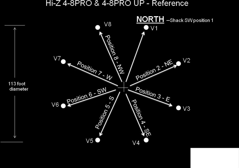
9 9 Fig. 8 Connecting the Phase Controller to the Shack Switch and Receiver Fig. 3, 4 & 5 1. Connect CNTL3 (these are located on the Hi-Z PnP controller) to shack CTRL3 on the switch. 2. Wire the power 13.8 VDC and Ground from shack switch to either of the controllers.fig.9 3. OPTIONS. If a HPF or BPF filter was purchased or customer supplied, the filter MUST be inserted between the controller output and before the inline preamp (best IMD). 4. Connect feed RG6 to the output of the in-line pre-amp to the Hi-Z 75 to 50Ω transformer in the shack and the other end of the transformer connects to the RX input. 5. Use your existing power cable at the existing Hi-Z 4 shack switch for your new 8 direction shack switch. Fig. 9 Shack Preparation and Basic Operation 1. Locate the placement of the shack switch. 2. Verify the voltage level is in the 13.8 VDC area. Depending on the length of the control cable this voltage may need to be adjusted upwards to compensate for any voltage drop. 3. Direction control. Typically; Position 1 = N, 2= NE, 3 = E, 4 = SE, 5 = S, 6 = SW, 7 = W and 8 = NW. Power Up and System Checks
10 10 1. Turn power on at the shack switch. One yellow direction LED should be ON. Rotate the direction rotary switch and verify that all 8 LEDs sequence correctly. 2. Measure the voltage at the phase controller. 13.8VDC is ideal. Voltage must be >=12.0 VDC. 3. Check the RED LEDs at the Hi-Z PLUS6 Amps at the base of each vertical, they should ALL be ON. 4. Tune to 160 or 80 meters. Switch On and Off the power at the Hi-Z shack switch and you should hear the noise floor increase when switched ON. If able, compare to existing antennas, the noise floor on the Hi-Z system will likely be much lower. 5. Test the directivity by tuning the AM broadcast band above 1 MHz (with no HPF or BPF filter installed). When pointed at a station and the signal is peaked, turn the control to other directions and observe the F/B and F/S. 6. On the air, especially low angle DX, you will observe best performance in terms of pattern. When a signal is peaked in one direction, try switching in the direction either side you will see the signal decrease considerably. As you continue to turn the direction control and observing the signal level, the F/S and F/B performance will become apparent. 7. The advantage is the S/N that our system produces. Good DX ing. TROUBESHOOTING also see Symptom: Spurs every 10 KHz across 160 meters. Check the Hi-Z PLUS6 Amp connections one of the Hi-Z PLUS6 Amp has the two wires (Antenna, Ground) reversed, verify these connections are wired correctly. Some switching power supplies can cause this symptom. Measure the DC voltage on the vertical. From ground to the vertical with a DVM you should measure ~4 volts VDC. Improper voltage readings indicate wiring problem. Low IMD. Verify that the voltage at the +13.8VDC and Ground terminals at the phase controller measures >=12.0 VDC. Sometimes due to control cable lengths one may need to consider a separate adjustable voltage power supply to insure correct operation voltage for the Hi-Z system. Hi-Z PLUS6 Amps No RED LED ON Verify that there is a jumper on the phase controller between the 13.8 VDC and Coax Power In terminals. Birdies, Heterodyning Causes include close proximity to broadcast stations. Solutions: One the source of this problem is located, the insertion of either a Hi-Z BPF or Hi-Z HPF, depending on the source of interference, should be inserted between the output of the phase controller and the input to the 75Ω in-line pre-amp. Directions Seem Wrong Verify that you connected vertical 1 to controller Ant1, vertical 2 to controller Ant 2 and so on. For other topics see technical & application notes at
11 11 HIGH PERFORMANCE HF RECEIVING SYSTEMS & COMPONENTS Hi-Z Antennas Hi-Z PLUS6 Amplifier Hi-Z PLUS6 Amplifier The Hi-Z PLUS6 Amplifier was designed to provide amplification and matching between the short verticals and the phase controller in the Hi-Z phased array control systems. This amplifier is used on ALL Hi-Z phased array products. The amp is located at the base of each short vertical. The connecting wires must be short, in the range or 8-10 inches long. When dressing or routing the wires between the vertical and ground rod to the Hi-Z PLUS6 Amps, maintain as much separation between the ground and antenna wires as possible. If these wires are to close it will degrade the system performance. The Hi-Z PLUS6 Amp MUST be Weatherproofed!! Please review our application and technical notes to gain ideas for mounting the Hi-Z PLUS6 amplifiers near the base of the verticals. See: Features: Relay input (lightning and static protection, when power is off)


12 12 Easy connections to the base of the vertical and ground Terminals to Ground and Vertical Hi-Z PLUS6 Amp RG6 Output THANK YOU for selecting Hi-Z Antennas. Hi-Z Antennas 8125 SW Larch Drive Culver, OR USA Vertical Orientation

13 13


14 14 8 Circle Array Layout of Verticals V1 V8 = Verticals 1-8. Each vertical is 45 degrees spacing. MODEL Diameter Radius A B C Hi-Z 4-8PRO 113 * ¾ / /16 Hi-Z 4-8PRO 84.5 ** / / /8 NOTE: All measurements are rounded to the nearest 1/16. * Based on Hi-Z 4 80 foot square footprint. ** Based on Hi-Z 4 60 foot square footprint. All coaxes from controller to the vertical are equal length (Radius + 4 feet).


15 15 APPENDIX A F connector tightening procedure. Placing a 7/16 wrench on the chassis connector while holding it tight, place another 7/16 wrench over the Male connector housing and tighten until snug. Do not over tighten this F connector. View pictures below.
Hi-Z Antennas Hi-Z 2 / Hi-Z 2-3 Element Array Manual
 1 HIGH PERFORMANCE HF RECEIVING SYSTEMS & COMPONENTS Hi-Z Antennas Hi-Z 2 / Hi-Z 2-3 Element Array Manual Hi-Z 2, Hi-Z 2-3 Phase controller left and Shack Switch - right Hi-Z 2-3 Shack Switch Hi-Z Verticals
Hi-Z Antennas Hi-Z 4 Element Array Manual Level 2 Hi-Z Amp PLUS6 (Hi-Z PLUS6 information is located at the end of this manual) 1/14/2014
 1/14/2014") 1 HIGH PERFORMANCE HF RECEIVING SYSTEMS & COMPONENTS Hi-Z Antennas Hi-Z 4 Element Array Manual Level 2 Hi-Z Amp PLUS6 (Hi-Z PLUS6 information is located at the end of this manual) 1/14/2014 Hi-Z 4 Element
1 HIGH PERFORMANCE HF RECEIVING SYSTEMS & COMPONENTS Hi-Z Antennas Hi-Z 4 Element Array Manual Level 2 Hi-Z Amp PLUS6 (Hi-Z PLUS6 information is located at the end of this manual) 1/14/2014 Hi-Z 4 Element
Hi-Z Antennas Hi-Z 3 Triangular 3 Element Array Manual Level 2 Hi-Z Amp PLUS6 PLUS6 Information is located at the end of this manual
 1 HIGH PERFORMANCE HF RECEIVING SYSTEMS & COMPONENTS Hi-Z Antennas Hi-Z 3 Triangular 3 Element Array Manual Level 2 Hi-Z Amp PLUS6 PLUS6 Information is located at the end of this manual Triangular 3 Element
Hi-Z USB Wireless. Introduction/Welcome
 Hi-Z USB Wireless Introduction/Welcome Thank you for selecting the Hi-Z Antennas USB Wireless system. The Hi-Z USB Wireless system provides control functions from a personal computer to operate a Hi-Z
IDC-136II-KIT 136kHz DC RX Assembly Guide
 IDC-136II-KIT 136kHz DC RX Assembly Guide ICAS Enterprises May 2 nd,2016 The IDC-136II-KIT is a 136kHz direct conversion receiver. Most of the SDR software can be used with this receiver. It is quite easy
ASSEMBLY AND INSTALLATION INSTRUCTIONS 738XB 70 CM OSCAR BOOMER MHz COMMUNICATIONS ANTENNAS (7/94)
") ASSEMBLY AND INSTALLATION INSTRUCTIONS 7XB 70 CM OSCAR BOOMER 432-4 MHz COMMUNICATIONS ANTENNAS 951451 (7/94) WARNING THIS ANTENNA IS AN ELECTRICAL CONDUCTOR. CONTACT WITH POWER LINES CAN RESULT IN DEATH,
ASSEMBLY AND INSTALLATION INSTRUCTIONS 7XB 70 CM OSCAR BOOMER 432-4 MHz COMMUNICATIONS ANTENNAS 951451 (7/94) WARNING THIS ANTENNA IS AN ELECTRICAL CONDUCTOR. CONTACT WITH POWER LINES CAN RESULT IN DEATH,
1100 Series Piston Type Differential Pressure Gauges
 1100 Series Piston Type Differential Pressure Gauges 1. Safety Before installing, check the Series Number and verify compatibility to the process media and temperature in contact with the wetted parts.
Norcal Power/SWR Meter Assembly & Operating Manual. Revision 1D 10/15/2008
 Norcal Power/SWR Meter Assembly & Operating Manual Revision 1D 10/15/2008 Copyright 2008 NorCal QRP Club Page 1 of 21 Contents CONTENTS...2 INTRODUCTION...3 SPECIFICATIONS...3 ASSEMBLY...4 OPERATING GUIDE...15
INSTRUCTION MANUAL_. Specifications. Electrical.
 308 Industrial Park Road Starkville, MS 39759 USA Ph: (662) 323-9538 FAX: (662) 323-6551 DX-77A 7-Band HF Vertical 10, 12, 15, 17, 20, 30, 40-Meter INSTRUCTION MANUAL_ General Description The "DX-77-A"
Nanometrics Solar Power System
 Nanometrics Solar Power System Installation Guide Nanometrics Inc. Kanata, Ontario Canada 2003 Nanometrics Inc. All Rights Reserved. Installation Guide The information in this document has been carefully
Weatherproof Tubular Slip Ring Assembly
 Weatherproof Tubular Slip Ring Assembly Model B8-4.3W 8 circuit weatherproof slip ring Compact design Mounts on shafts up to 4.3 [109.2 mm] in diameter Permanently lubricated bearings Rugged stainless
Designed for 2014 and newer 1500 Series and 2015 and newer Heavy Duty GM Silverado/Sierra Double Cab vehicles
 19303116 Designed for 2014 and newer 1500 Series and 2015 and newer Heavy Duty GM Silverado/Sierra Double Cab vehicles Subwoofer Assembly Subwoofer Body Harness 25A Fuse Wire Ties x 6 Wire Taps x 2 Adapter
SOLAR LIGHTING CONTROLLER SUNLIGHT MODELS INCLUDED IN THIS MANUAL SL-10 SL-10-24V SL-20 SL-20-24V
 SOLAR LIGHTING CONTROLLER OPERATOR S MANUAL SUNLIGHT MODELS INCLUDED IN THIS MANUAL SL-10 SL-10-24V SL-20 SL-20-24V 10A / 12V 10A / 24V 20A / 12V 20A / 24V 1098 Washington Crossing Road Washington Crossing,
Multi-band Bi-SectorTM Array
 DATA SHEET Patented twin asymmetric beam 33 Bi-Sector array phase array over a frequency range of (698-896 MHz) and (1710-2360 MHz), optimized to match existing cloverleaf (65 ) deployments. 4 low band
INSTALLATION INSTRUCTIONS:
 INSTALLATION INSTRUCTIONS: The CA-5030 is an ultrasonic parking assist system designed for use on the rear bumper of most cars and trucks. This system detects any people or objects behind the vehicle using
APOLLO Gate Operators, Inc.
 APOLLO Gate Operators, Inc. Model 3500ETL/3600ETL Commercial Swing Gate Operator INSTALLATION MANUAL 01/08 CONTENTS IMPORTANT SAFETY INSTRUCTIONS. 3 Applications... 4 Pre-Installation Checklist... 5 Parts
CAT-1 Series 3. Installation Guide. The Valley Group, Inc. 871 Ethan Allen Hwy. Suite 104 Ridgefield, CT 06877
 CAT-1 Series 3 Installation Guide The Valley Group, Inc. 871 Ethan Allen Hwy. Suite 104 Ridgefield, CT 06877 (203) 431-0262 (203) 431-0296 FAX tvg@cat-1.com Installation of Load Cells for CAT-1 Systems
Downloaded From SatelliteGuys.US - America's Satellite Information Source!
 Attention and Warning Symbols You must be aware of safety when you install and use this system. This guide provides various procedures. If you do some of these procedures carelessly, you could injure or
HexPort Multi-Band Antenna
 DATA SHEET Four foot (1.2 m), six port antenna with a 65 azimuth beamwidth covering 698-894 MHz and 1710-2360 MHz Four high band and two low band ports including the WCS band in a single antenna Sharp
MODEL 8002SW (1996 MSRP $ )
") F O R T H E L O V E O F M U S I C MODEL 8002SW (1996 MSRP $1549.00) INSTALLATION AND OPERATION MANUAL INTRODUCTION Congratulations, with all the auto sound equipment available on the market today, decisions
F O R T H E L O V E O F M U S I C MODEL 8002SW (1996 MSRP $1549.00) INSTALLATION AND OPERATION MANUAL INTRODUCTION Congratulations, with all the auto sound equipment available on the market today, decisions
SL Series Application Notes. SL Series - Application Notes. General Application Notes. Wire Gage & Distance to Load
 Transportation Products SL Series - Application Notes General Application Notes vin 2 ft. 14 AWG The SL family of power converters, designed as military grade standalone power converters, can also be used
Assembly Instructions for the KA Electronics Flat MM Phono Preamplifier
 Assembly Instructions for the KA Electronics Flat MM Phono Preamplifier Install IC sockets Flat MM Phono Preamp PC Board Stuffing Guide Place the PC Board on the bench silkscreen side face up. Drop six
Installation Instructions Table of Contents
 Installation Instructions Table of Contents Pre- Installation of Garage Storage Lift 2 Layout the Garage Storage Lift 3 Installing the strut Channels 3 Install the Drive Assembly 5 Install the Drive Shaft
Rx antennas at IV3PRK: detuning the TX Antenna
 Rx antennas at IV3PRK: detuning the TX Antenna Using the sectionalizing tower method by W8JI by Pierluigi Luis Mansutti IV3PRK In the 1 st part of my modeling study on the Flags upgrade, from the original
Installation Instructions for VTU
 Installation Instructions for VTU 1 Introduction This installation manual covers the installation of the Vehicle Tracking Unit (VTU). This manual is for the professional and novice installer and should
Model RP310 Owner's Manual & Installation Instructions
 INSTALLATION AND INSTRUCTION MANUAL REMOTE STROBE PACK Model RP310 Owner's Manual & Installation Instructions PLITSTR223 REV. B 3/3/11 Table of Contents SAFETY WARNINGS 1 MOUNTING 2 WIRING INSTRUCTIONS
CLASSIC PEDAL KIT. Assembly Instructions WHEN YOU CAN T BUY IT BUILD IT. StewMac Monarch RARE / VINTAGE / HARD TO GET
 Sheet #i-2205 Updated 2/8 StewMac Monarch CLASSIC PEDAL KIT Kit case is unpainted IN COLLABORATION WITH EarthQuakerDevices Assembly Instructions The Monarch Overdrive is an all discrete, FET-based dirt
Chapter 2. Battery Charger and Base Assembly
 Chapter 2 Battery Charger and Base Assembly 11 CHAPTER 2. BATTERY CHARGER AND BASE ASSEMBLY 2.1 Section Overview This Lab teaches students how to assemble a Tekbot, in the following steps: Describe the
How to Install and Operate the LXA300 Amplifier. Contents. Technical Assistance
 How to Install and Operate the LXA300 Amplifier POWER L R HI INPUT LOW INPUT BASS -BOOST ON OFF LEVEL MIN MAX LPF HPF LPF L R PASS 50 250 HPF 50 250 PROTECT Welcome! What you're holding in your hands is
INSTALLATION MANUAL & OPERATING INSTRUCTIONS
 INSTALLATION MANUAL & OPERATING INSTRUCTIONS SIGALARM MODEL 210 PMB 405; West SR 46 Sanford, FL 32771 (800) 589-3769 (407) 328-9479 Fax: (407) 328-5889 Email:info@sigalarminc.com Internet: http://www.sigalarminc.com
LI-2B Installation Manual
 ARCO Pty. Ltd. LI-2B Intelligent Gate Controller Installation/Owners Manual Please do not commence installation until you have read this instruction book. Contents: Introduction Installation Options: Standard
INSTALLATION GUIDE Car Show Dual DVD Headrest Replacement System
 INSTALLATION GUIDE Car Show Dual DVD Headrest Replacement System NOTICE OF INTENDED INSTALLATION AND USE CAR SHOW VIDEO PRODUCTS ARE NOT INTENDED FOR VIEWING BY THE DRIVER, AND ARE TO BE INSTALLED ONLY
OctoPort Multi-Band Antenna
 DATA SHEET Six foot (1.8 m), eight port antenna with an 45 azimuth beamwidth covering 698-787 MHz, 824-896 MHz and 1695-2180 MHz Four high band and four low band ports in a single antenna Sharp elevation
REFERENCE MANUAL FORM: MX-TRM-E REL REV MTE
 Matrix APAX 380V-415V 50Hz TECHNICAL REFERENCE MANUAL FORM: MX-TRM-E REL. September 2014 REV. 002 2014 MTE Corporation WARNING High Voltage! Only a qualified electrician can carry out the electrical installation
8 Channel Intelligent Digital Line Output Converter with Auxiliary Input and Remote Level Control OWNERS MANUAL
 8 Channel Intelligent Digital Line Output Converter with Auxiliary and Remote Level Control OWNERS MANUAL 1 Introduction Thank you for purchasing Pacific Audio Corporations (PAC) 8ch intelligent line output
TI23 Pre-Instructional Survey
 TI23 Pre-Instructional Survey Name: Date: 1. Identify the balloon contents that represent the relationship between the three electrical measurements as they relate to Ohm s Law. 2. Which of the statements
TRAC-3 TENSION READOUT AND CONTROL
 Magnetic Power Systems, Inc. 1626 Manufacturers Drive. Fenton, MO 63026 Tel: 636.343.5550 Fax: 636.326.0608 magpowr@magpowr.com INSTRUCTION MANUAL TRAC-3 READOUT AND CONTROL For Control of Magnetic Particle
1000 Series Piston Type Differential Pressure Gauges
 1000 Series Piston Type Differential Pressure Gauges 1. Safety Before installing, check the Series Number and verify compatibility to the process media and temperature in contact with the wetted parts.
FLEX-6000 GPSDO Installation Guide
 FLEX-6000 GPSDO Installation Guide October 15, 2013 Thank you for purchasing the FLEX-6000 GPSDO Kit. The following guide will provide the necessary stepby-step procedure for installing the FLEX-6000 GPSDO
Low Profile 8 150watt Amplified Subwoofer Installation Instructions
 Low Profile 8 150watt Amplified Subwoofer Installation Instructions Radio Engineering Industries, Inc. www.radioeng.com Rev A 5/12/14 Thank you for purchasing the 150Watt Amplified Subwoofer from REI.
OWNER S MANUAL. Please read installation and operation instruction before using this Power inverter.
 OWNER S MANUAL DP AUDIO Model No. DN350 12 Volt DC to 115 Volt AC 150 WATT 300WATT HIGH SURGE POWER INVERTER Please read installation and operation instruction before using this Power inverter. Contents
INSTALLATION GUIDE. AV8900H Dual Multimedia Headrest Replacement System
 INSTALLATION GUIDE AV8900H Dual Multimedia Headrest Replacement System NOTICE OF INTENDED INSTALLATION AND USE AV8900H VIDEO PRODUCTS ARE NOT INTENDED FOR VIEWING BY THE DRIVER, AND ARE TO BE INSTALLED
Electrical Wiring Practices
 Chapter 2 Electrical Wiring Practices and Diagrams MElec-Ch2-1 Overview Safety Standards Wiring Considerations Wire Terminations Coaxial Cable Wiring Installations Wiring Diagrams MElec-Ch2-2 Safety Lethal
GT-R Alpha 10/12 Turbo Kit
 GT-R Alpha 10/12 Turbo Kit Instructions V6 The goal of AMS is to provide the highest quality, best performing products available. By utilizing research and development, and rigorous testing programs AMS
EMC- Components. Feed-Through Capacitors Feed-Through Filters in Solderless MKP Technology. Data Book Supplement
 EMC- Components Feed-Through Capacitors Feed-Through Filters in Solderless MKP Technology Data Book Supplement Vakatseite (( 2 )) Feed- Through Capacitors Feed- Through Filters B85121 B85321 1 General
NATIONAL RADIO ASTRONOMY OBSERVATORY RADIO FREQUENCY INTERFERENCE SUPPRESSION ON THE 1972 CHEVROLET VEGA. James L. Dolan.
 NATIONAL RADIO ASTRONOMY OBSERVATORY RADIO FREQUENCY INTERFERENCE SUPPRESSION ON THE 1972 CHEVROLET VEGA James L. Dolan August 1972 At the direction of S. Weinreb, a 1972 Chevrolet Vega, squareback model,
CABINET REEL OPERATING INSTRUCTIONS
 CABINET REEL OPERATING INSTRUCTIONS MODELS 15, 25, 40 & 60 SERIES RAPID-AIR CORPORATION 4601 KISHWAUKEE ST. ROCKFORD, IL 61109-2925 Phone: (815) 397-2578 Fax: (815) 398-3887 Web Site: www.rapidair.com
INSTALLATION GUIDE AV7900 Dual Multimedia Headrest Replacement System
 INSTALLATION GUIDE AV7900 Dual Multimedia Headrest Replacement System NOTICE OF INTENDED INSTALLATION AND USE AV7900 VIDEO PRODUCTS ARE NOT INTENDED FOR VIEWING BY THE DRIVER, AND ARE TO BE INSTALLED ONLY
Installation Instructions
 Quick-Mount Visual Instructions for Quick-Mount Visual Instructions 1. Rotate the damper to its failsafe position. If the shaft rotates counterclockwise, mount the CCW side of the actuator out. If it rotates
Expansion Signal (XSIG) Card Installation Instructions
 Card Installation Instructions") Expansion Signal (XSIG) Card Installation Instructions Introduction This publication describes the installation procedure for the Expansion Signal (XSIG) Card (4100-5116). This product is compatible with
Expansion Signal (XSIG) Card Installation Instructions Introduction This publication describes the installation procedure for the Expansion Signal (XSIG) Card (4100-5116). This product is compatible with
12 Meter Add-On Kit for the Hustler 4/5/6-BTV Vertical Antennas
 12 Meter Add-On Kit for the Hustler 4/5/6-BTV Vertical Antennas DXE-AOK-12M Patent Pending DXE-AOK-12M-INS Revision 1d DXE-AOK-12M Installed on a BTV with optional Tilt Base and Direct Coax Feedpoint DX
White Light CLASSIC PEDAL KIT. Assembly Instructions WHEN YOU CAN T BUY IT BUILD IT. StewMac RARE / VINTAGE / HARD TO GET
 Sheet #i-2206 Updated 5/18 StewMac White Light CLASSIC PEDAL KIT Kit case is unpainted IN COLLABORATION WITH EarthQuakerDevices Assembly Instructions The White Light Overdrive is based on vintage overdrives
SIGNETMARINE. Livewell Bait Pump Alarm. No Dead Bait.
 B A I T WAT C H SIGNETMARINE Livewell Bait Pump Alarm No Dead Bait. The SIGNETMARINE BaitWatch System alerts you to a livewell pump problem before your fishing trip turns into one. The loud alarm and dual-color
Rogator Passive Roll (2012+) 5 Height Sensors Installation Manual RG11
 5 Height Sensors Installation Manual RG11") RG11 Rogator Passive Roll (2012+) 5 Height Sensors Installation Manual Printed in Canada Copyright 2009 by NORAC Systems International Inc. Reorder P/N: UC5-BC-RG11-INST Rev E (Rogator Passive Roll (2012+)
RG11 Rogator Passive Roll (2012+) 5 Height Sensors Installation Manual Printed in Canada Copyright 2009 by NORAC Systems International Inc. Reorder P/N: UC5-BC-RG11-INST Rev E (Rogator Passive Roll (2012+)
Aquavar SPD Plus SIMPLEX VARIABLE SPEED SUBMERSIBLE AND ABOVE GROUND PUMP CONTROLLER BRSPDP R2
 SIMPLEX VARIABLE SPEED SUBMERSIBLE AND ABOVE GROUND PUMP CONTROLLER BRSPDP R2 SPD Plus Do you want to simplify your commercial pumping system and save energy? CentriPro SPD Plus variable speed, constant
WPS-2800 SERIES HIGH POWER VOICE & SIREN SYSTEM
 ENGINEERING COMPANY INC. Route 45, Winthrop Road, Chester, Connecticut 0642 Phone: (800) 63SIREN Phone: (860) 526-9504 Fax: (860) 526-4078 Internet: www.whelen.com Sales e-mail: iowsales@whelen.com Customer
MALLORY FIRESTORM CD MULTI COIL HARDWARE INSTALLATION - PN 69050S / 69050R
 FORM 69050S/R MALLORY FIRESTORM CD MULTI COIL HARDWARE INSTALLATION - PN 69050S / 69050R To ensure you are using the most current instruction sheet, please visit www.malloryfirestorm.com. CAUTION! The
IVTM Installation Manual
 Integrated Vehicle Tire Pressure Monitoring IVTM Installation Manual 2nd edition Copyright WABCO 2006 Vehicle Control Systems An American Standard Company The right of amendment is reserved Version 002/06.06(us)
Units with pedestal and busbars on the short side (+H360, flat mounting)
") 91 Units with pedestal and busbars on the short side (+H360, flat mounting) Delivery check Check that there are no signs of damage. Before attempting installation and operation, check the information on
91 Units with pedestal and busbars on the short side (+H360, flat mounting) Delivery check Check that there are no signs of damage. Before attempting installation and operation, check the information on
Quarter Master Chief Series 92 Actuator
 Quarter Master Chief Series 92 Actuator Installation, Operation and Maintenance Manual File: Series 92 O & M manual Rev. V 4/22/2013 Page 1 of 13 Table of Contents Series 92 Electric Actuator Introduction...
Proper installation of this product requires the installer to have a good understanding of automotive electronics, systems and procedures.
 ENGINEERING COMPANY INC. 51 Winthrop Road Chester, Connecticut 06412-0684 Phone: (860) 526-9504 Fax: (860) 526-4078 Internet: www.whelen.com Sales e-mail: autosale@whelen.com Canadian Sales e-mail: autocan@whelen.com
Wired Real Time GPS Installation Instructions
 Wired Real Time GPS Installation Instructions This page intentionally left blank. TABLE OF CONTENTS 1. Introduction 2 2. Selecting the Mounting Location for the Device. 3 3. Mounting the Device 5 4. Optional
METROLOGIC INSTRUMENTS, INC. MX001 Industrial Control Interface Installation and User s Guide
 METROLOGIC INSTRUMENTS, INC. MX001 Industrial Control Interface Installation and User s Guide Copyright 2007 by Metrologic Instruments, Inc. All rights reserved. No part of this work may be reproduced,
SS & SS SOFT-START v3.0 ASSEMBLY & INSTALLATION INSTRUCTIONS
 SS-221-120 & SS-221-240 SOFT-START v3.0 ASSEMBLY & INSTALLATION INSTRUCTIONS WARNING: Voltages inside the amplifier CAN & WILL KILL YOU! You MUST know how to work around HIGH VOLTAGE safely. If you do
Art. No. EC-315. Art. No. EC-330. Art. No. EC-340 SWITCH-MODE BATTTERY CHARGER CONTENTS IMPORTANT SAFETY PRECAUTIONS... 2
 SWITCH-MODE BATTTERY CHARGER CONTENTS IMPORTANT SAFETY PRECAUTIONS... 2 DESCRIPTION AND FEATURES... 3 CHARGING STAGES... 4 Art. No. EC-315 Art. No. EC-330 Art. No. EC-340 PROTECTIONS... 5 INSTALLATION...
MODEL 8682 SUREFLOW ADAPTIVE OFFSET CONTROLLER
 MODEL 8682 SUREFLOW ADAPTIVE OFFSET CONTROLLER INSTALLATION INSTRUCTIONS WARNING: The Model 8682 Adaptive Offset Controller must be wired to 24 VAC only. Wiring the unit to 110 VAC will cause serious unit
INSTALLATION INSTRUCTIONS:
 INSTALLATION INSTRUCTIONS: The CA-5010.II is an ultrasonic parking assist system designed for use on the rear bumper of most cars and trucks. This system detects any people or objects behind the vehicle
PRAMCQ13. Designed for Dodge Ram vehicles with base audio Not Compatible with 2018 and newer Dodge Ram vehicles
 PRAMCQ13 Designed for 2013 2017 Dodge Ram vehicles with base audio Not Compatible with 2018 and newer Dodge Ram vehicles Subwoofer Alternate Amplifier Bracket Amplifier Subwoofer Harness Subwoofer Amplifier
OIL FIELD ELECTRIC ACTUATOR INSTRUCTION MANUAL SPECIAL APPLICATIONS ACTUATORS Q 6.0.1
 OIL FIELD ELECTRIC ACTUATOR INSTRUCTION MANUAL SPECIAL APPLICATIONS ACTUATORS Q 6.0.1 This instruction manual contains important information regarding the installation, operation, and troubleshooting of
Manual Installation & Operation
 Manual Installation & Operation Model: NCxxLxx 12A or 30A Solid State Solar Charging Regulator and 12A Load Controller. 231 Patent #: 5,642,030 Applies Page 1 Warnings When Installing, connect grounds,
G213V STEP MOTOR DRIVE REV 7: March 25, 2011
 Thank you for purchasing the G213V drive. The G213V is part of Geckodrive s new generation of CPLD-based microstep drives. It has short-circuit protection for the motor outputs, over-voltage and under-voltage
Mid to High Power FM Antennas
 Mid to High Power FM Antennas FMM Series FMP Series Micronetixx builds two mid to high power FM antenna families, the FMM, and the FMP. Both series of antennas are constructed from rugged stainless steel
Wireless Temperature/Humidity Station
 Wireless Temperature/Humidity Station Installation Manual For Vantage Pro2 and Vantage Pro2 Plus The Wireless Temperature/Humidity Station, referred to as the Temp/Hum Station in this manual, is for use
ELECTRO-MECH SCOREBOARD CO.
 ELECTRO-MECH SCOREBOARD CO. MM-338 FOOTBALL SCOREBOARD OWNER S HANDBOOK Thank you for choosing an Electro-Mech Scoreboard for your athletic complex. We are confident that your new scoreboard will give
VCN-2000 VENOM Nitrous System
 VCN-2000 VENOM Nitrous System Installation/Operation Manual Software Installation Harness Installation Hose Installation COMPLETELY READ THIS MANUAL BEFORE STARTING INSTALLATION Copyright 2000 Python Injection,
BRSDRIVE ITT. Goulds Pumps. S-Drive. Simplex Variable Speed Submersible Pump Controller. Engineered for life
 ITT BRSDRIVE Goulds Pumps Simplex Variable Speed Submersible Pump Controller C U L US Engineered for life Do you want to Simplify your Commercial Pumping System? Goulds Pumps S-Drive variable speed, constant
SHIFNOID WIRING DIAGRAM FOR a B&M PRO RATCHET with SN5070 SOLENOID KIT
 SHIFNOID WIRING DIAGRAM FOR a B&M PRO RATCHET with SN5070 SOLENOID KIT IF YOUR RPM SWITCH OR TIMER SUPPLIES "NORMALLY OPEN GROUND" (SHIFNOID OR MSD) USE THIS DIAGRAM IF YOUR RPM SWITCH OR TIMER SUPPLIES
Step 1: Parts List and Bike Preparation
 Step 1: Parts List and Bike Preparation Please be sure to read our instructions thoroughly before attempting installation. Check Parts list supplied with your kit to be sure all parts are handy. If something
Sensor SNS06 Shown. Monitor. Toughened Nut Sensor Installation Instructions With thread detection calibration procedures. 1.
 1. System Components Cable (Sold Seperately) Blue Black To Customer's Control Sensing Area Monitor Adjustment Potentiometer Sensor SNS06 Shown Load On LED Power On LED Monitor 2. Technical Data Monitor
C H A P T E R ➂. Installation. Installation Precautions. Environmental Considerations. Wiring Considerations
 C H A P T E R ➂ Installation Installation Precautions The information in this chapter will enable you to: Ensure that the complete system is installed correctly Mount all system components properly Before
FM200 FLOW/NO-FLOW MONITOR INSTALLATION AND TECHNICAL MANUAL 120 VAC MODEL 6/1/2017
 FM200 FLOW/NO-FLOW MONITOR INSTALLATION AND TECHNICAL MANUAL 120 VAC MODEL 6/1/2017 Maxi-Tronic, Inc. 417 Wards Corner Road Loveland, OH 45140 513.398.2500 800.659.8250 FAX: 513.398.2536 info@maxitronic.com
 Page 1 of 6 Page 2 of 6 Page 3 of 6 RADIO WORKS' WEB STORE Available at the RADIO WORKS' Web Store CAROLINA WINDOM 160 Compact $189 Do you need coax or antenna support line? Return to Web Store Index SPECIFICATIONS
Homebrew Travel Antenna
 Homebrew Travel Antenna This is a low cost homebrew two band travel antenna for 20 and 40 meters. It is based on the B&W Travel Antenna concept with a telescoping whip and a loading coil. A piece of 1/8
USER MANUAL QUICK INSTALLATION GUIDE MRGB65B
 USER MANUAL QUICK INSTALLATION GUIDE MRGB65B MARINE GRADE RGB 6.5 COAX SPEAKERS USER MANUAL QUICK INSTALLATION GUIDE MRGB65B MARINE GRADE 6.5 COAX SPEAKERS BOSS Audio Systems 3451 Lunar Court Oxnard, CA
Flexible Loop coil (for AT-5000 and AT-7500 battery powered telemetry):
:") Stationary Pickup Coil Selection Guide for Accumetrics Telemetry This guide is intended to provide users with information about the range of pickup coil variations employed for Accumetrics rotor telemetry
Stationary Pickup Coil Selection Guide for Accumetrics Telemetry This guide is intended to provide users with information about the range of pickup coil variations employed for Accumetrics rotor telemetry
PMC-MC-X2-Chassis PMC-MC-X4-Chassis
 DYNAMIC ENGINEERING 150 DuBois St Suite 3, Santa Cruz Ca 95060 831-457-8891 Fax 831-457-4793 http://www.dyneng.com sales@dyneng.com Est. 1988 User Manual Four Slot Carrier Two Slot Carrier PMC-MC-X2-Chassis
E D C K R A E T S I D TURNOUT CONTROLLER 8S USER MANUAL
 S I D E T R A C K E D TURNOUT CONTROLLER 8S USER MANUAL INDEX 1. WHAT YOU SHOULD HAVE 3 2. FEATURES OF THE 3 3. WARRANTY 3 4. ABOUT THIS MANUAL 3 5. CONNECTORS AND DESCRIPTIONS 3 6. WIRING 7 6.1. CONTROL
OWNERS MANUAL. Model No LB. PUSH BROADCAST SPREADER. Assembly Operation Maintenance Repair Parts
 OWNERS MANUAL Model No. 45-02102-101 SHIELD UP - 8 TO 18 FT. SPREAD WIDTH SHIELD DOWN - 3 TO 4 FT. SPREAD WIDTH 125 LB. PUSH BROADCAST SPREADER CAUTION: Read Rules for Safe Operation and Instructions Carefully
SMT-BM 20 A BMM 05 F BMM 05 AF
 gb SMT-BM 20 A BMM 05 F BMM 05 AF SINGLE-AXIS RACKS 1 2 SINGLE-AXIS RACKS This is a general manual describing a series of racks receiving servo amplifiers having output capability suitable for driving
3M Occupational Health & Environmental Safety Division 3M SoundPro Outdoor Kit Instructions
 3M Occupational Health & Environmental Safety Division 3M SoundPro Outdoor Kit Instructions 3M SoundProTM Outdoor Measuring System (SP-OMS) The SoundPro Outdoor Measuring System helps protect the instrument
Series BFM Bulk Flow Monitor 1A FUSE RED LED RELAY. Part Number BFM-1 BFM-2 BFM-3 BFS-1
 Series Bulk Flow Monitor Specifications - Installation and Operating Instructions Bulletin FL-1-4x 3/4 CONDUIT KNOCKOUTS BFS 1A FUSE RED LED RELAY 5-9/64 [130.45] TRANSFORMER 3[76.20] GREEN LED 7 [177.80]
ME868PIB SMART INTERLOCK TECHNOLOGY TURBO FLO LE PROXIMITY INTERLOCK BRACKET INSTALLATION AND OPERATING INSTRUCTIONS
 ME868PIB SMART INTERLOCK TECHNOLOGY TURBO FLO LE PROXIMITY INTERLOCK BRACKET INSTALLATION AND OPERATING INSTRUCTIONS ME868-16 Turbo-Flo LE Adapter (Not Included) ME441F8 Cap (Not Included) ME868PIB Application:
Quarter Master Series 94 Actuator
 Quarter Master Series 94 Actuator Installation, Operation and Maintenance Manual Assembly Series 94 Manual Rev V 9/5/13 Page 1 of 12 Table of Contents Series 94 Electric Actuator Introduction... 3 Description...
Onboard. Onboard RTU270 Installation Manual
 Onboard Onboard RTU270 Installation Manual Contents Parts Checklist 3 Pre-installation considerations 4 Installation 5 Status LEDs 7 Completing Installation 8 2 Onboard RTU270 Installation Parts Check
100A Series Low Power FM Antenna
 Installation Instructions 100A Series Low Power FM Antenna Types 100A-1M, 100A-2F, 100A-2F-HW 20100326001_AEN Revision 03 Notice The installation, maintenance, or removal of antenna systems requires qualified,
RE Generation II Troubleshooting Guide Section I Preliminary Information and Evaluation
 DODGE ENGINEERING & CONTROLS, INC. 196 Riverneck Road Chelmsford, MA 01824 PHONE (978) 244-1200 FAX (978) 244-1422 TOLL FREE (877) 334-2875 RE Generation II Troubleshooting Guide Section I Preliminary
Model 1550 Single Swing Gate Model 1650 Dual Swing Gate
 Gate Operators, Inc. Model 1550 Single Swing Gate Model 1650 Dual Swing Gate Swing Gate Operator CONTENTS Safety Precautions... 2 Applications... 3 Pre-Installation Checklist... 4 Parts Identification...
T his chapter contains instructions for installing the RICON S-Series (ADA) Transit Use Wheelchair and Standee Lift
 Transit Use Wheelchair and Standee Lift") II. INSTALLATION T his chapter contains instructions for installing the RICON S-Series (ADA) Transit Use Wheelchair and Standee Lift with Manual Rollstop into most vans and buses, although custom installations
II. INSTALLATION T his chapter contains instructions for installing the RICON S-Series (ADA) Transit Use Wheelchair and Standee Lift with Manual Rollstop into most vans and buses, although custom installations
Table of Contents SMA CONNECTORS
 Table of Contents 45 SMA Connectors 3 MMCX Connectors 50 Ohm Connectors Specifications...46 Quick Connect...49 Semi-Rigid & Flexible Cable...50 PC Mount...56 Bulkhead & Panel Mount...62 Self-Fixture End
user s manual 10-Channel Active Electronic Crossover Network with Subwoofer Level Control OptiX-10
 user s manual www.lanzar.com OptiX-10 10-Channel Active Electronic Crossover Network with Subwoofer Level Control INTRODUCTION... Congratulations on your purchase of a new Lanzar Opti signal processor.