Hi-Z Antennas Hi-Z 4 Element Array Manual Level 2 Hi-Z Amp PLUS6 (Hi-Z PLUS6 information is located at the end of this manual) 1/14/2014
|
|
|
- Calvin McLaughlin
- 5 years ago
- Views:
Transcription
 1/14/2014 Hi-Z 4 Element Array")

1 1 HIGH PERFORMANCE HF RECEIVING SYSTEMS & COMPONENTS Hi-Z Antennas Hi-Z 4 Element Array Manual Level 2 Hi-Z Amp PLUS6 (Hi-Z PLUS6 information is located at the end of this manual) 1/14/2014 Hi-Z 4 Element Array System Hi-Z Verticals Congratulations and Thank You for the purchase of our system. We recommend that you read this manual and fully understand the requirements for the proper installation of your system. Specifications

2 2 Maximum RDF 12.1db Directions 4 Power Requirements 13.8 VDC Pattern Material That the Customer Supplies - 1. Control cable (4 conductor-- 2 wires for control and 2 for power) 2. Short two conductor cable for DC power. Hi-Z supplies the connector for the shack switch. 3. Mounts for the verticals. 4. Four short ground rods. Depending on soil type, in the range of 3 4 feet long. 5. RG6 coax and connectors (connecting the verticals to the phase controller and from phase controller / in-line preamp to shack receiver location. RG6 coax is more than adequate to lengths out to 1000 feet long. 6. Make eight 9-10 long wires. Wire size can be made from gauge wire. Terminate each end with #6 ring terminals. Recommend that after the terminals are crimped, that these terminals are soldered for reliability. For Hi- Z Amp terminations. 7. Weatherproofing the electronics. You will need an adequate cover or enclosure that will keep rain and snow off the phase controller, in-line pre-amp and filters if installed, and the Hi-Z PLUS6 Amps at the base of each vertical. Water getting inside of these enclosures WILL cause DAMAGE. OPTIONS Filters for site specific issues, for example local and or high power AM broadcast stations. Hi-Z Antennas makes a BPF look at and a HPF look at SITE PREPARATION Place the verticals as far away from metallic structures or other towers and antennas as possible, especially resonant antennas. The farther the better. Keep away from field fencing at least feet. Keep the verticals more then 10 feet from trees and heavy vegetation. Control Cable and Coax Considerations 1. Conductor wire gauge size is a function of the length of the control cable. 18 gauge wires is adequate out to 500 feet. Any longer will need to increase wire gauge size to accommodate the voltage drop over the run of cable length. An inexpensive source of cable is from Lowes, Home Depot, etc in their electrical department. They have 5, 7, 9 conductor, 18 gauge direct burial sprinkler control cable. Usually they will have it on large spools and can be cut to the length you require. Always get extra. 2. Make sure that the RG6 connectors are tight. 3. If you crimp on terminals on the control cable, go the extra step and solder each terminal for reliability.
 will be mounted. 2.")
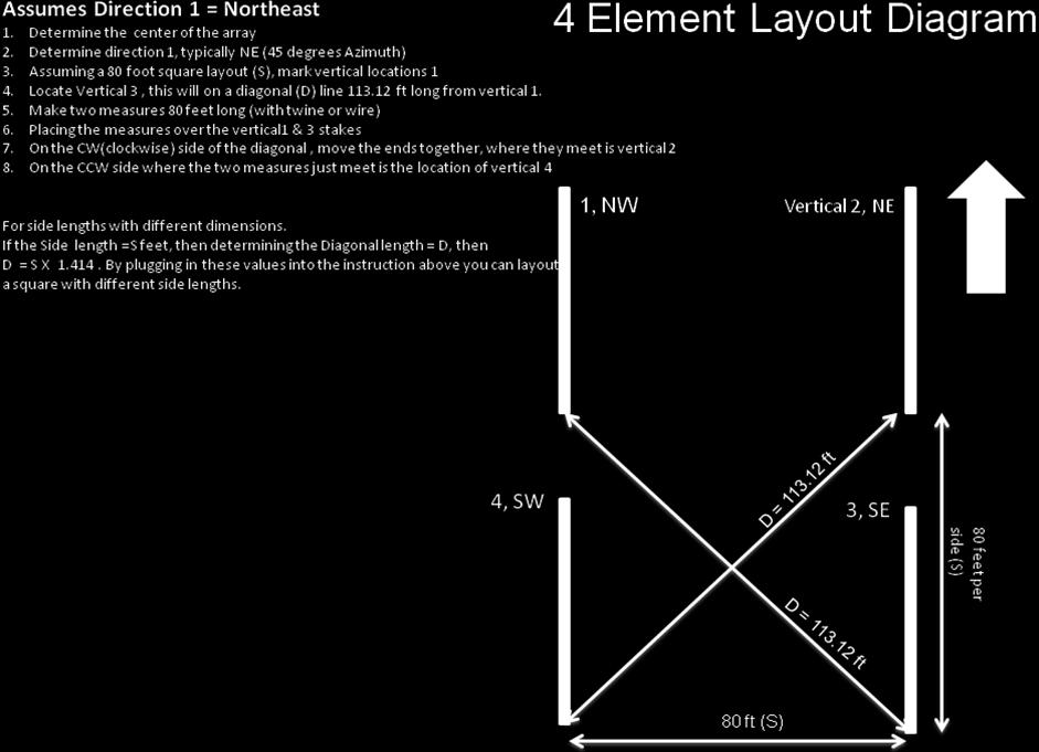
3 3 Vertical Placement and Installation of the Hi-Z PLUS6 Amplifiers Typically the phase controller is mounted in the center of the array, but that is not necessary as long as ALL four RG6 coaxes are cut to the same length and can reach from the controller to all three verticals. 1. Determine where the array (verticals) will be mounted. 2. The verticals need to be as far away as possible from other antennas, tower and other metallic structures. Especially if the other antennas are resonant, this will lower performance. 3. Locate the ground rods close to the base of each vertical. 4. Determine the direction orientation. You have 4 directions. So orientation of the verticals is critical to achieving the directional performance you require and can be different in locations around the world. There is a procedure to assist you in laying out the verticals at your site at the end of this manual. 5. See the diagram on the last page. This will assist you in laying out the accurate placement of your three verticals. 6. Acquire control cable (4 conductor) long enough to get from the shack switch to the phase controller. 7. You will need a length of RG6 coax about the same length to connect the output of the in-line pre-amp (at the phase controller) to your receiver port. 8. Typically the phase controller is located in the center of the array. That is not necessary. However where ever the phase controller is located the four RG6 coaxes from the controller to the base of each vertical MUST be cut and terminated to the same length 9. Mount the 4 the verticals (either homebrew or Hi-Z verticals). 10. Mount the Hi-Z Amplifiers PLUS6 at the base of each vertical. Connect one wire from the Antenna terminal to the base of the vertical. Connect another wire from the Ground terminal to the ground rod. See Hi-Z Amplifier. 11. Connect a RG6 coax from output of Hi-Z amp PLUS6 to the correct Ant 1, 2, 3 and 4 at the controller. 12. Weatherproofing of the Hi-Z Amp PLUS6 is not necessary, except to seal the RG6 coax connection. Hi-Z Amp PLUS6 Connecting the Verticals and Delay Cable to the Phase Controller


4 4 Fig. 1 Fig Run equal lengths of RG6 from the controller to each vertical. This connects to the controller Ant 1-4 to verticals 1-4. Be certain to observe these connections based on the orientation or placement of verticals for correct aiming. Fig.1 Ant1, direction 1 is Northeast, Ant2 is direction 2 and is Northeast, Ant3 is position3 and is Southeast, Ant4 is direction 4 and is Southwest. 2. Connect the Hi-Z supplied short and long Delay cables at Short Delay and Long Delay connectors on the phase controller. Fig.2 Connecting the Phase Controller to the Shack Switch and Receiver Fig. 3, 4 & 5 1. Wire point to point control 1 and 2 between controller and shack switch. Fig. 3, 4 & 5 2. Wire the power (13.8 VDC and Ground from shack switch to the controller. 3. Connect a short length of RG6 from the phase controller output to the input of the inline pre-amp. Fig OPTIONS. If a HPF or BPF filter was purchased or customer supplied, the filter MUST be inserted between the controller output and before the inline preamp (best IMD). 5. Connect a short wire from the 13.8 VDC controller terminal to the 13.8 VDC terminal at the inline pre-amp. Fig Connect RG6 from the output of the inline pre-amp to your receiver. Fig OPTION. If you purchased our Hi-Z 75 to 50Ω transformer, then insert the transformer in the feed coax in the shack. We highly recommend this transformer for best overall performance.


5 5 Fig. 3 Fig. 4 The phase controller will be supplied with a RED jumper connected between the 13.8 VDC and Coax Power In terminals. This supplies the voltage to the Hi-Z amps over the coax. Fig. 5 Fig. 6 Shack Preparation and Basic Operation 1. Locate the placement of the shack switch. 2. Hi-Z Antennas provides a power connector, on the back of the switch. Build a power cable to suit your needs and connect to your DC power supply. Center connector is +13.8VDC and the shield is Ground. Fig.5 3. Verify the voltage level is in the 13.8 VDC area. Depending on the length of the control cable this voltage may need to be adjusted upwards to compensate for any voltage drop.
6 6 4. Direction control. Typically the yellow LED (Upper Right) position is direction 1 (Northwest). Turning the selection switch clockwise in order will select directions 1 4. Typically direction number 1 is oriented to NW. Then in order position 2 is Northeast, 3 is Southeast and 4 is Southwest. Power Up and System Checks 1. Turn power on at the shack switch. One yellow direction LED should be ON. 2. Measure the voltage at the phase controller. 13.8VDC is ideal. Voltage must be >=12.0 VDC. 3. Check the RED LEDs at the Hi-Z Amp PLUS6 at the base of each vertical, they should ALL be ON. 4. Connect to receiver (through optional Hi-Z 75 to 50 Ω transformer, recommended). 5. Tune to 160 or 80 meters. Switch On and Off the power at the Hi-Z shack switch and you should hear the noise floor increase when switched ON. If able, compare to existing antennas, the noise floor on the Hi-Z system will likely be lower. 6. Test the directivity by tuning the top end of the AM broadcast band (with no HPF or BPF filter installed). When pointed at a station and the signal is peaked, turn the control to other directions and observe the F/B and F/S. 7. On the air, especially low angle DX, you will observe best performance in terms of pattern. When a signal is peaked in one direction, try switching in the direction either side you will see the signal decrease considerably. As you continue to turn the direction control and observing the signal level, the F/S and F/B performance will become apparent. 8. The advantage is the S/N that our system produces. Good DX ing. TROUBESHOOTING also see Symptom: Spurs every 10 KHz across 160 meters. Check the Hi-Z PLUS6 connections. One of the Hi-Z Amp PLUS6 has the two wires (Antenna, Ground) backwards, verify these connections are wired correctly. Measure the DC voltage on the vertical. From ground to the vertical with a DVM you should measure ~4 volts VDC. Some switching power supplies can cause this symptom. Low IMD. Verify that the voltage at the +13.8VDC and Ground terminals at the phase controller measures >=12.0 VDC. Sometimes due to control cable lengths one may need to consider a separate adjustable voltage power supply to insure correct operation voltage for the Hi-Z system. Hi-Z Amps No RED LED ON Verify that there is a jumper on the phase controller between the 13.8 VDC and Coax Power In terminals. Birdies, Heterodyning Causes include close proximity to broadcast stations. Solutions: One the source of this problem is located, the insertion of either a Hi-Z BPF or Hi-Z HPF, depending on the source of interference, should be inserted between the output of the phase controller and the input to the 75Ω in-line pre-amp. Directions Seem Wrong Verify that you connected vertical 1 to controller Ant1, vertical 2 to controller Ant 2 and so on. For other topics see technical & application notes at

7 7
8 8 HIGH PERFORMANCE HF RECEIVING SYSTEMS & COMPONENTS Hi-Z Antennas Hi-Z Amplifier Hi-Z Amplifier PLUS6 The Hi-Z PLUS6 Amplifier was designed to provide amplification and matching between the short verticals and the phase controller in the Hi-Z phased array control systems. This amplifier is used on ALL Hi-Z phased array products. The amp is located at the base of each short vertical. The connecting wires must be short, in the range or 8-10 inches long. When dressing or routing the wires between the vertical and ground rod to the Hi-Z Amps, maintain as much separation between the ground and antenna wires as possible. If these wires are to close it will degrade the system performance. Please review our application and technical notes to gain ideas for mounting the Hi-Z amplifiers near the base of the verticals. See: Features: Relay input (lightning and static protection, when power is off) Easy connections to the base of the vertical and ground
9 9 Terminals to Ground and Vertical Hi-Z Amp RG6 Output
10 10 HIGH PERFORMANCE HF RECEIVING SYSTEMS & COMPONENTS Hi-Z Antennas Hi-Z Amplifier PLUS6 Hi-Z Amplifier PLUS6 The Hi-Z Amplifier PLUS6 was designed to provide amplification and matching between the short verticals and the phase controller in the Hi-Z phased array control systems. This amplifier is used on ALL Hi-Z phased array products. The amp is located at the base of each short vertical. The connecting wires must be short, in the range or 8-10 inches long. When dressing or routing the wires between the vertical and ground rod to the Hi-Z Amps, maintain as much separation between the ground and antenna wires as possible. If these wires are too close it will degrade the system performance. Please review our application and technical notes to gain ideas for mounting the Hi-Z amplifiers near the base of the verticals. See: Specifications: Increased gain model PLUS6 0dB (both models maintain 75 ohm output impedance) L=4.6 W=2.6 H=1.6 (not including the terminals or connectors) Features & Benefits:
 and")

11 11 Rugged weatherized enclosure No need to cover the amp, simplified mounting Reduces cost (enclosures) and time to mount and connect the Amp to the vertical elements Terminals to Ground and Vertical Hi-Z Amp RG6 Output

12 12 Mounting Detail: THANK YOU for selecting Hi-Z Antennas. Hi-Z Antennas 8125 SW Larch Drive Culver, OR USA
Hi-Z Antennas Hi-Z 3 Triangular 3 Element Array Manual Level 2 Hi-Z Amp PLUS6 PLUS6 Information is located at the end of this manual
 1 HIGH PERFORMANCE HF RECEIVING SYSTEMS & COMPONENTS Hi-Z Antennas Hi-Z 3 Triangular 3 Element Array Manual Level 2 Hi-Z Amp PLUS6 PLUS6 Information is located at the end of this manual Triangular 3 Element
Hi-Z Antennas Hi-Z 2 / Hi-Z 2-3 Element Array Manual
 1 HIGH PERFORMANCE HF RECEIVING SYSTEMS & COMPONENTS Hi-Z Antennas Hi-Z 2 / Hi-Z 2-3 Element Array Manual Hi-Z 2, Hi-Z 2-3 Phase controller left and Shack Switch - right Hi-Z 2-3 Shack Switch Hi-Z Verticals
Hi-Z Antennas 4-8 PRO UP Level2 8 Element Circle Array Manual Converts the Hi-Z 4 to the Hi-Z 4-8PRO
 1 HIGH PERFORMANCE HF RECEIVING SYSTEMS & COMPONENTS Hi-Z Antennas 4-8 PRO UP Level2 8 Element Circle Array Manual Converts the Hi-Z 4 to the Hi-Z 4-8PRO Hi-Z 4-8PRO Shack Switch Hi-Z 4-8PRO PnP Interface
IDC-136II-KIT 136kHz DC RX Assembly Guide
 IDC-136II-KIT 136kHz DC RX Assembly Guide ICAS Enterprises May 2 nd,2016 The IDC-136II-KIT is a 136kHz direct conversion receiver. Most of the SDR software can be used with this receiver. It is quite easy
ASSEMBLY AND INSTALLATION INSTRUCTIONS 738XB 70 CM OSCAR BOOMER MHz COMMUNICATIONS ANTENNAS (7/94)
") ASSEMBLY AND INSTALLATION INSTRUCTIONS 7XB 70 CM OSCAR BOOMER 432-4 MHz COMMUNICATIONS ANTENNAS 951451 (7/94) WARNING THIS ANTENNA IS AN ELECTRICAL CONDUCTOR. CONTACT WITH POWER LINES CAN RESULT IN DEATH,
ASSEMBLY AND INSTALLATION INSTRUCTIONS 7XB 70 CM OSCAR BOOMER 432-4 MHz COMMUNICATIONS ANTENNAS 951451 (7/94) WARNING THIS ANTENNA IS AN ELECTRICAL CONDUCTOR. CONTACT WITH POWER LINES CAN RESULT IN DEATH,
Onboard. Onboard RTU270 Installation Manual
 Onboard Onboard RTU270 Installation Manual Contents Parts Checklist 3 Pre-installation considerations 4 Installation 5 Status LEDs 7 Completing Installation 8 2 Onboard RTU270 Installation Parts Check
MODEL 8002SW (1996 MSRP $ )
") F O R T H E L O V E O F M U S I C MODEL 8002SW (1996 MSRP $1549.00) INSTALLATION AND OPERATION MANUAL INTRODUCTION Congratulations, with all the auto sound equipment available on the market today, decisions
F O R T H E L O V E O F M U S I C MODEL 8002SW (1996 MSRP $1549.00) INSTALLATION AND OPERATION MANUAL INTRODUCTION Congratulations, with all the auto sound equipment available on the market today, decisions
Hi-Z USB Wireless. Introduction/Welcome
 Hi-Z USB Wireless Introduction/Welcome Thank you for selecting the Hi-Z Antennas USB Wireless system. The Hi-Z USB Wireless system provides control functions from a personal computer to operate a Hi-Z
How to Install and Operate the LXA300 Amplifier. Contents. Technical Assistance
 How to Install and Operate the LXA300 Amplifier POWER L R HI INPUT LOW INPUT BASS -BOOST ON OFF LEVEL MIN MAX LPF HPF LPF L R PASS 50 250 HPF 50 250 PROTECT Welcome! What you're holding in your hands is
Flexible Loop coil (for AT-5000 and AT-7500 battery powered telemetry):
:") Stationary Pickup Coil Selection Guide for Accumetrics Telemetry This guide is intended to provide users with information about the range of pickup coil variations employed for Accumetrics rotor telemetry
Stationary Pickup Coil Selection Guide for Accumetrics Telemetry This guide is intended to provide users with information about the range of pickup coil variations employed for Accumetrics rotor telemetry
Weatherproof Tubular Slip Ring Assembly
 Weatherproof Tubular Slip Ring Assembly Model B8-4.3W 8 circuit weatherproof slip ring Compact design Mounts on shafts up to 4.3 [109.2 mm] in diameter Permanently lubricated bearings Rugged stainless
INSTRUCTION MANUAL_. Specifications. Electrical.
 308 Industrial Park Road Starkville, MS 39759 USA Ph: (662) 323-9538 FAX: (662) 323-6551 DX-77A 7-Band HF Vertical 10, 12, 15, 17, 20, 30, 40-Meter INSTRUCTION MANUAL_ General Description The "DX-77-A"
Assembly Instructions for the KA Electronics Flat MM Phono Preamplifier
 Assembly Instructions for the KA Electronics Flat MM Phono Preamplifier Install IC sockets Flat MM Phono Preamp PC Board Stuffing Guide Place the PC Board on the bench silkscreen side face up. Drop six
TI23 Pre-Instructional Survey
 TI23 Pre-Instructional Survey Name: Date: 1. Identify the balloon contents that represent the relationship between the three electrical measurements as they relate to Ohm s Law. 2. Which of the statements
OIL FIELD ELECTRIC ACTUATOR INSTRUCTION MANUAL SPECIAL APPLICATIONS ACTUATORS Q 6.0.1
 OIL FIELD ELECTRIC ACTUATOR INSTRUCTION MANUAL SPECIAL APPLICATIONS ACTUATORS Q 6.0.1 This instruction manual contains important information regarding the installation, operation, and troubleshooting of
Mid to High Power FM Antennas
 Mid to High Power FM Antennas FMM Series FMP Series Micronetixx builds two mid to high power FM antenna families, the FMM, and the FMP. Both series of antennas are constructed from rugged stainless steel
ME868PIB SMART INTERLOCK TECHNOLOGY TURBO FLO LE PROXIMITY INTERLOCK BRACKET INSTALLATION AND OPERATING INSTRUCTIONS
 ME868PIB SMART INTERLOCK TECHNOLOGY TURBO FLO LE PROXIMITY INTERLOCK BRACKET INSTALLATION AND OPERATING INSTRUCTIONS ME868-16 Turbo-Flo LE Adapter (Not Included) ME441F8 Cap (Not Included) ME868PIB Application:
APOLLO Gate Operators, Inc.
 APOLLO Gate Operators, Inc. Model 3500ETL/3600ETL Commercial Swing Gate Operator INSTALLATION MANUAL 01/08 CONTENTS IMPORTANT SAFETY INSTRUCTIONS. 3 Applications... 4 Pre-Installation Checklist... 5 Parts
Installation Instructions for VTU
 Installation Instructions for VTU 1 Introduction This installation manual covers the installation of the Vehicle Tracking Unit (VTU). This manual is for the professional and novice installer and should
SIGNETMARINE. Livewell Bait Pump Alarm. No Dead Bait.
 B A I T WAT C H SIGNETMARINE Livewell Bait Pump Alarm No Dead Bait. The SIGNETMARINE BaitWatch System alerts you to a livewell pump problem before your fishing trip turns into one. The loud alarm and dual-color
INSTALLATION INSTRUCTIONS:
 INSTALLATION INSTRUCTIONS: The CA-5030 is an ultrasonic parking assist system designed for use on the rear bumper of most cars and trucks. This system detects any people or objects behind the vehicle using
CROSS FIELD ARRAY-2 (CFA-2) Long Throw/High Intelligibility All-Weather Loudspeaker System V100/2015
 Long Throw/High Intelligibility All-Weather Loudspeaker System V100/2015") CROSS FIELD ARRAY-2 (CFA-2) Long Throw/High Intelligibility All-Weather Loudspeaker System V100/2015 The One Systems Cross Field Array-2 (CFA-2) was designed to provide very high intelligibility and acoustic
CROSS FIELD ARRAY-2 (CFA-2) Long Throw/High Intelligibility All-Weather Loudspeaker System V100/2015 The One Systems Cross Field Array-2 (CFA-2) was designed to provide very high intelligibility and acoustic
Designed for 2014 and newer 1500 Series and 2015 and newer Heavy Duty GM Silverado/Sierra Double Cab vehicles
 19303116 Designed for 2014 and newer 1500 Series and 2015 and newer Heavy Duty GM Silverado/Sierra Double Cab vehicles Subwoofer Assembly Subwoofer Body Harness 25A Fuse Wire Ties x 6 Wire Taps x 2 Adapter
USER MANUAL QUICK INSTALLATION GUIDE MRGB65B
 USER MANUAL QUICK INSTALLATION GUIDE MRGB65B MARINE GRADE RGB 6.5 COAX SPEAKERS USER MANUAL QUICK INSTALLATION GUIDE MRGB65B MARINE GRADE 6.5 COAX SPEAKERS BOSS Audio Systems 3451 Lunar Court Oxnard, CA
Model RP310 Owner's Manual & Installation Instructions
 INSTALLATION AND INSTRUCTION MANUAL REMOTE STROBE PACK Model RP310 Owner's Manual & Installation Instructions PLITSTR223 REV. B 3/3/11 Table of Contents SAFETY WARNINGS 1 MOUNTING 2 WIRING INSTRUCTIONS
Series BFM Bulk Flow Monitor 1A FUSE RED LED RELAY. Part Number BFM-1 BFM-2 BFM-3 BFS-1
 Series Bulk Flow Monitor Specifications - Installation and Operating Instructions Bulletin FL-1-4x 3/4 CONDUIT KNOCKOUTS BFS 1A FUSE RED LED RELAY 5-9/64 [130.45] TRANSFORMER 3[76.20] GREEN LED 7 [177.80]
1100 Series Piston Type Differential Pressure Gauges
 1100 Series Piston Type Differential Pressure Gauges 1. Safety Before installing, check the Series Number and verify compatibility to the process media and temperature in contact with the wetted parts.
Seal Beach Police Department
 Seal Beach Police Department Emergency Services Trailer Operating Manual Prepared by the Seal Beach/Los Alamitos RACES Group Rick Shab, KB6VCM and Mike Maronta KC6YNQ Emergency Services Trailer Page 1
Homebrew Travel Antenna
 Homebrew Travel Antenna This is a low cost homebrew two band travel antenna for 20 and 40 meters. It is based on the B&W Travel Antenna concept with a telescoping whip and a loading coil. A piece of 1/8
GTFM IV. Operation / Installation Manual. Gas Turbine Flow Monitor. Computer Weld Technology, Inc. Manual Part Number: A8M5010 Revised: June 26, 2008
 Computer Weld Technology, Inc. 10702 Old Bammel N Houston Rd. Houston, TX 77086 Phone: (713) 462-2118 Fax: (713) 462-2503 Email: cwt@cweldtech.com GTFM IV Gas Turbine Flow Monitor Operation / Installation
Electrical Wiring Practices
 Chapter 2 Electrical Wiring Practices and Diagrams MElec-Ch2-1 Overview Safety Standards Wiring Considerations Wire Terminations Coaxial Cable Wiring Installations Wiring Diagrams MElec-Ch2-2 Safety Lethal
Wireless Temperature/Humidity Station
 Wireless Temperature/Humidity Station Installation Manual For Vantage Pro2 and Vantage Pro2 Plus The Wireless Temperature/Humidity Station, referred to as the Temp/Hum Station in this manual, is for use
Index. Index...pag.1. General features...pag.2 Mechanical features Available size. Electrical features pag.3 Protections Signalling Led
 MANUAL Micro Driver Via Ilaria Alpi N 6 - zona industriale - Lonato (BS) Tel. 030/9913491r.a. Fax. 030/9913504 http://www.re-elettronica.it E-mail : info@re-elettronica.it Pag. 1 Index Index........pag.1
Troubleshooting Bosch Proportional Valves
 Troubleshooting Bosch Proportional Valves An Informative Webinar Developed by GPM Hydraulic Consulting, Inc. Instructed By Copyright, 2009 GPM Hydraulic Consulting, Inc. TABLE OF CONTENTS Bosch Valves
3M Occupational Health & Environmental Safety Division 3M SoundPro Outdoor Kit Instructions
 3M Occupational Health & Environmental Safety Division 3M SoundPro Outdoor Kit Instructions 3M SoundProTM Outdoor Measuring System (SP-OMS) The SoundPro Outdoor Measuring System helps protect the instrument
Cleveland-Kidder Ultra
 LOW PROFILE Low Profile Load Cell Providing up to a 40:1 Tension Range Performance Benefits Cleveland Motion Controls new Ultra Line Slim Cell is part of the new Line Tension family. a unique low-profile
Bill Conkling July 2012
 Bill Conkling July 2012 Introduction: For any ham, there are moments that are priceless, like snagging that elusive rare DX station on a deserted island that hasn t been activated in 52 years. And certainly,
100 Watt Power Amp 50 Watts x 50 Watts Single Rack Space
 User's Manual 100 Watt Power Amp 50 Watts x 50 Watts Single Rack Space 1 Introduction Congratulations on your purchase of the Rocktron Velocity 100LTD power amplifier! The Velocity 100LTD was designed
ARC4000e 4 wheel compressor system w / 4 way Ride Pro controller
 350 S. St. Charles St. Jasper, In. 47546 Ph. 812.482.2932 Fax 812.634.6632 on the internet: www.ridetech.com ARC4000e 4 wheel compressor system w / 4 way Ride Pro controller 1 ARC5001 Compressor 1 CON6000
CAT-1 Series 3. Installation Guide. The Valley Group, Inc. 871 Ethan Allen Hwy. Suite 104 Ridgefield, CT 06877
 CAT-1 Series 3 Installation Guide The Valley Group, Inc. 871 Ethan Allen Hwy. Suite 104 Ridgefield, CT 06877 (203) 431-0262 (203) 431-0296 FAX tvg@cat-1.com Installation of Load Cells for CAT-1 Systems
SOLAR LIGHTING CONTROLLER SUNLIGHT MODELS INCLUDED IN THIS MANUAL SL-10 SL-10-24V SL-20 SL-20-24V
 SOLAR LIGHTING CONTROLLER OPERATOR S MANUAL SUNLIGHT MODELS INCLUDED IN THIS MANUAL SL-10 SL-10-24V SL-20 SL-20-24V 10A / 12V 10A / 24V 20A / 12V 20A / 24V 1098 Washington Crossing Road Washington Crossing,
Electric Actuator Instructions
 BAC IOM Electric Actuator Instructions E024, E025, E026, E029 & E030 TABLE OF CONTENTS Electric Actuator Specifications...2 Overview...3 Actuator Wiring Diagrams...4 VMS-35 Specifications and Wiring Diagram...5
Model No. SB1B-14 Linear Standby Regulator. B & C Specialty Products P.O. Box B Newton, KS (316)
") Installation Instructions for Model No. SB1B-14 Linear Standby Regulator With Over-Voltage Protection B & C Specialty Products P.O. Box B Newton, KS 67114 (316) 283-8000 SB1B-14_Install, Rev. A (12/12/14)
Installation Instructions for Model No. SB1B-14 Linear Standby Regulator With Over-Voltage Protection B & C Specialty Products P.O. Box B Newton, KS 67114 (316) 283-8000 SB1B-14_Install, Rev. A (12/12/14)
ENGINE GOVERNING SYSTEMS
 ENGINE GOVERNING SYSTEMS ESD5400 Series Speed Control Unit INSTALLATION The speed control unit is rugged enough to be placed in a control cabinet or engine mounted enclosure with other dedicated control
 Page 1 of 6 Page 2 of 6 Page 3 of 6 RADIO WORKS' WEB STORE Available at the RADIO WORKS' Web Store CAROLINA WINDOM 160 Compact $189 Do you need coax or antenna support line? Return to Web Store Index SPECIFICATIONS
INSTRUCTION MANUAL MODEL PS VDC POWER SUPPLY
 222 W. Memorial Road, Oklahoma City, OK 73114-2317 Phone: 1-800-624-7697 Fax: 405-755-8425 www.magpowr.com E-mail: magpowr@magpowr.com INSTRUCTION MANUAL MODEL PS-24 24 VDC POWER SUPPLY All of the information
Model FS-30N FS-52N FS-60N FS-100N Type Mount Speaker
 WALL SPEAKER FS-30N/52N/60N/100N FS Series is designed for high quality, professional sound reproduction which is ideal for BGM playback and paging. With the high quality transformer can minimize losses
6. BI-AMPLIFIER AND SINGLE-AMPLIFIER OPERATIONS 6.1. Bi-Amplifier Operation Single-Amplifier Operation... 9
 LINE ARRAY SPEAKERS OPERATING INSTRUCTIONS SR-C8L SR-C8S SR-C15B RIGGING FRAME RIGGING SUPPORT BRACKET TILT JOINT BRACKET CLUSTER BRACKET SR-RF8 SR-SB8 SR-TP8 SR-CL8 Note that casters must be prepared
FM200 FLOW/NO-FLOW MONITOR INSTALLATION AND TECHNICAL MANUAL 120 VAC MODEL 6/1/2017
 FM200 FLOW/NO-FLOW MONITOR INSTALLATION AND TECHNICAL MANUAL 120 VAC MODEL 6/1/2017 Maxi-Tronic, Inc. 417 Wards Corner Road Loveland, OH 45140 513.398.2500 800.659.8250 FAX: 513.398.2536 info@maxitronic.com
Revision THERMO TECHNOLOGIES. USDT 2001 Differential Controller. Installation and User s Guide
 Revision 8 THERMO TECHNOLOGIES USDT 2001 Differential Controller Installation and User s Guide USDT 2001 DIFFERENTIAL CONTROLLER Installation and User s Guide Table of Contents Introduction General Information
MODEL 2202 ( MSRP $549.00)
") F O R T H E L O V E O F M U S I C MODEL 2202 (1989 - MSRP $549.00) OWNER S OPERATION MANUAL AND INSTALLATION GUIDE INTRODUCTION Power Supply: Self oscillating for reliability and efficiency. The transformer
F O R T H E L O V E O F M U S I C MODEL 2202 (1989 - MSRP $549.00) OWNER S OPERATION MANUAL AND INSTALLATION GUIDE INTRODUCTION Power Supply: Self oscillating for reliability and efficiency. The transformer
California Friendly Landscape Training
 California Friendly Landscape Training Irrigation Course Irrigation System Troubleshooting Course originally developed by California Polytechnic State University, San Luis Obispo Irrigation Training &
Art. No. EC-315. Art. No. EC-330. Art. No. EC-340 SWITCH-MODE BATTTERY CHARGER CONTENTS IMPORTANT SAFETY PRECAUTIONS... 2
 SWITCH-MODE BATTTERY CHARGER CONTENTS IMPORTANT SAFETY PRECAUTIONS... 2 DESCRIPTION AND FEATURES... 3 CHARGING STAGES... 4 Art. No. EC-315 Art. No. EC-330 Art. No. EC-340 PROTECTIONS... 5 INSTALLATION...
TRAC-3 TENSION READOUT AND CONTROL
 Magnetic Power Systems, Inc. 1626 Manufacturers Drive. Fenton, MO 63026 Tel: 636.343.5550 Fax: 636.326.0608 magpowr@magpowr.com INSTRUCTION MANUAL TRAC-3 READOUT AND CONTROL For Control of Magnetic Particle
MAPNET II Transceiver Installation Instructions
 MAPNET II Transceiver Installation Instructions Introduction This publication describes the installation procedure for the following versions of the MAPNET II Transceiver card. 4120/4100-0110 MAPNET II
Manual Installation & Operation
 Manual Installation & Operation Model: NCxxLxx 12A or 30A Solid State Solar Charging Regulator and 12A Load Controller. 231 Patent #: 5,642,030 Applies Page 1 Warnings When Installing, connect grounds,
EZ-MOUNT WEATHER STATION
 EZ-MOUNT WEATHER STATION INSTALLATION MANUAL This manual describes how to install the EZ-Mount weather station. Separate manuals included with the station cover the operation of the console and sensors.
3143 Production Drive Fairfeild, Ohio Model HA-45. Installation and Service Manual
 3143 Production DriveFairfeild, Ohio 45014513-874-3733 Model HA-45 Installation and Service Manual 3143 Production DriveFairfeild, Ohio 45014513-874-3733 Model HA-45 Installation and Service Manual Table
ELECTRIC ACTUATOR HVAC/BAC ELECTRIC IOM. E024, EO25, E026, EO29 & E030 Installation Operation and Maintenance Instructions TABLE OF CONTENTS
 HVAC/BAC ELECTRIC IOM ELECTRIC ACTUATOR E024, EO25, E026, EO29 & E030 Installation Operation and Maintenance Instructions TABLE OF CONTENTS Electric Actuator Specifications... 2 Overview... 3 Actuator
NATIONAL RADIO ASTRONOMY OBSERVATORY RADIO FREQUENCY INTERFERENCE SUPPRESSION ON THE 1972 CHEVROLET VEGA. James L. Dolan.
 NATIONAL RADIO ASTRONOMY OBSERVATORY RADIO FREQUENCY INTERFERENCE SUPPRESSION ON THE 1972 CHEVROLET VEGA James L. Dolan August 1972 At the direction of S. Weinreb, a 1972 Chevrolet Vega, squareback model,
Proper installation of this product requires the installer to have a good understanding of automotive electronics, systems and procedures.
 ENGINEERING COMPANY INC. 51 Winthrop Road Chester, Connecticut 06412-0684 Phone: (860) 526-9504 Fax: (860) 526-4078 Internet: www.whelen.com Sales e-mail: autosale@whelen.com Canadian Sales e-mail: autocan@whelen.com
Norcal Power/SWR Meter Assembly & Operating Manual. Revision 1D 10/15/2008
 Norcal Power/SWR Meter Assembly & Operating Manual Revision 1D 10/15/2008 Copyright 2008 NorCal QRP Club Page 1 of 21 Contents CONTENTS...2 INTRODUCTION...3 SPECIFICATIONS...3 ASSEMBLY...4 OPERATING GUIDE...15
ECU. Speed Switch Manual. Contents. ECU is a registered trademark of Engineering Concepts Unlimited Inc.
 ECU Speed Switch Manual Contents ECU is a registered trademark of Engineering Concepts Unlimited Inc. Contents Unit review Magnetic pickup example AC input example Design Guide Troubleshooting guide 24
datasheet TCS-122 TCS-122DP
 DP The is a two-way loudspeaker enclosure available in either switchable active/passive or optional digitally self-powered formats, and designed for use in a wide range of fixed installations. It consists
PRAMCQ13. Designed for Dodge Ram vehicles with base audio Not Compatible with 2018 and newer Dodge Ram vehicles
 PRAMCQ13 Designed for 2013 2017 Dodge Ram vehicles with base audio Not Compatible with 2018 and newer Dodge Ram vehicles Subwoofer Alternate Amplifier Bracket Amplifier Subwoofer Harness Subwoofer Amplifier
INSTALLATION MANUAL & OPERATING INSTRUCTIONS
 INSTALLATION MANUAL & OPERATING INSTRUCTIONS SIGALARM MODEL 210 PMB 405; West SR 46 Sanford, FL 32771 (800) 589-3769 (407) 328-9479 Fax: (407) 328-5889 Email:info@sigalarminc.com Internet: http://www.sigalarminc.com
A1P OPERATING MANUAL
 A1P OPERATING MANUAL TABLE OF CONTENTS Introduction... p. 2 Features... p. 2 Description... p. 3 Theory of Operation... p. 3 Installation... p. 4 Electrical Connections... p. 5 Options... p. 6 Warranty...
onlinecomponents.com
 Description Amphenol connectors are used in applications where maximum RF shielding and minimum noise radiation are required. Features/Benefits Available in 7/8-20 and 11/16-24 threading, C, BNC and TNC
Triax Amphenol. Description Amphenol Triax connectors are used in applications where maximum RF shielding and minimum noise radiation are required.
 Description Amphenol connectors are used in applications where maximum RF shielding and minimum noise radiation are required. Features/Benefits Available in 7/8-20 and 11/16-24 threading, C, BNC and TNC
Fincor DC Drives. Flexible & Powerful TYPICAL APPLICATIONS. Conveyor Rugged. Extruder Reliable. Conveyor Simple. Mixer Flexible
 DC Drives Flexible & Powerful single-phase DC drives provide a complete family solution from the compact Series 2120 chassis drive to the powerful Series 2230 and it s feature rich application specific
BMW F10 Premium / Professional Audio system - adding a sub woofer part two
 BMW F10 Premium / Professional Audio system - adding a sub woofer part two I accept no liability for any work carried out as a result of this guide. Any damage caused to equipment or your car (or you)
SlimRack Bed Lift System OEM INSTALLATION MANUAL
 SlimRack Bed Lift System OEM INSTALLATION MANUAL Rev: 07.11.2018 TABLE OF CONTENTS System Information 2 Safety Information 3 Resources Required 3 General Requirements 3 Installation 4 SlimRack Bed Lift
INSTALLATION INSTRUCTIONS:
 INSTALLATION INSTRUCTIONS: The CA-5010.II is an ultrasonic parking assist system designed for use on the rear bumper of most cars and trucks. This system detects any people or objects behind the vehicle
12 Meter Add-On Kit for the Hustler 4/5/6-BTV Vertical Antennas
 12 Meter Add-On Kit for the Hustler 4/5/6-BTV Vertical Antennas DXE-AOK-12M Patent Pending DXE-AOK-12M-INS Revision 1d DXE-AOK-12M Installed on a BTV with optional Tilt Base and Direct Coax Feedpoint DX
Ford AOD-4R70W-AODE Cable Operated Shifter Installation Instructions
 Ford AOD-4R70W-AODE Cable Operated Shifter Installation Instructions Building American Quality With A Lifetime Warranty! TOLL FREE 1-877-469-7440 tech@lokar.com www.lokar.com Ford AOD-4R70W-AODE Cable
Long-Range Barrier Sensors
 Long-Range Barrier Sensors Manual Model # of Beams Length E-9626-2B190Q 2 pairs 26 (66cm) E-9643-4B190Q 4 pairs 43 (109cm) E-9661-6B190Q 6 pairs 61 (155cm) E-9679-8B190Q 8 pairs 79 (201cm) 4 Different
Wide-Vue Analog Panel Meters
 UL Recognized - File # E91015 Except for the Wattmeters & Frequency Meters Clear acrylic window for wide viewing area Rugged black plastic case Black spade pointer for easy distant reading Optional: Behind-panel
Fig. 1. Sample calculation for determining the proper conductor size needed to serve a motor controller and avoid voltage drop problems.
 Power to the Pump By Mike Holt, NEC Consultant Why some fire pump requirements are "backward" One of the principal NEC requirements for circuit protection is that you shut down the equipment rather than
A6Z OPERATING MANUAL
 A6Z OPERATING MANUAL TABLE OF CONTENTS Introduction... p. 2 Features... p. 2 Description... p. 3 Theory of Operation... p. 3 Installation... p. 4 Electrical Connections... p. 5 Options... p. 6 Warranty.p.
REFERENCE MANUAL FORM: MX-TRM-E REL REV MTE
 Matrix APAX 380V-415V 50Hz TECHNICAL REFERENCE MANUAL FORM: MX-TRM-E REL. September 2014 REV. 002 2014 MTE Corporation WARNING High Voltage! Only a qualified electrician can carry out the electrical installation
Extreme Environment For high pressure, low temperature, and high temperature applications
 SENSOR DATA SHEET Extreme Environment For high pressure, low temperature, and high temperature applications 800-552-6267 kamansensors.com measuring@kaman.com Features v For applications requiring high
CP-1TT Remote System
 CP-1TT Remote System (9 volt & 12 volt systems) INSTALLATION/OPERATION MANUAL Manufactured by: Preferred Technologies Group www.cartell.com TABLE OF CONTENTS This Table of Contents is clickable. Point
GM A-Body Instructions 3 & 2½ Header Applications w/ Balance Tube Crossover
 GM A-Body Instructions 3 & 2½ Header Applications w/ Balance Tube Crossover Included with this kit are the following: 2 Collector Reducers 1 Balance Tube Kit A 2 Headpipes 2 Tailpipes 2 Tailpipe Extensions
ALTRONIC, INC. 712 TRUMBULLAVE. GIRARD, OHIO DIS. IGNITION SYSTEM 500 SERIES IMPORTANT SAFETY NOTICE
 ALTRONIC D.I.S. MEDIUM ENGINES, 4-16 CYLINDERS SERVICE INSTRUCTIONS FORM DIS SI 6-91 ALTRONIC, INC. 712 TRUMBULLAVE. GIRARD, OHIO 44420 DIS. IGNITION SYSTEM 500 SERIES IMPORTANT SAFETY NOTICE PROPER INSTALLATION,
Model 1550 Single Swing Gate Model 1650 Dual Swing Gate
 Gate Operators, Inc. Model 1550 Single Swing Gate Model 1650 Dual Swing Gate Swing Gate Operator CONTENTS Safety Precautions... 2 Applications... 3 Pre-Installation Checklist... 4 Parts Identification...
Installation Instructions for LED Timing Light
 Daytona Sensors LLC Engine Controls and Instrumentation Systems Installation Instructions for CAUTION: CAREFULLY READ INSTRUCTIONS BEFORE PROCEEDING OVERVIEW The P/N 120001 includes a versatile controller
Ford AOD-4R70W-AODE Cable Operated Shifter Installation Instructions
 Ford AOD-4R70W-AODE Cable Operated Shifter Installation Instructions Building American Quality With A Lifetime Warranty! TOLL FREE 1-877-469-7440 tech@lokar.com www.lokar.com Ford AOD-4R70W-AODE Cable
Rx antennas at IV3PRK: detuning the TX Antenna
 Rx antennas at IV3PRK: detuning the TX Antenna Using the sectionalizing tower method by W8JI by Pierluigi Luis Mansutti IV3PRK In the 1 st part of my modeling study on the Flags upgrade, from the original
How to Install and Remove a standard Teletrac Transceiver.
 How to Install and Remove a standard Teletrac Transceiver. April 27 2010 Draft: 001.fc.4_10.doc Introduction. This document is comprised of two independent sections. The first section addressed all the
FM Approved Remote Kit Assembly (Part No ) Standard Remote Kit Assembly (Part No ) G2 SERIES G2 Industrial METER MODULES
 Standard Remote Kit Assembly (Part No ) G2 SERIES G2 Industrial METER MODULES") G2 SERIES G2 Industrial METER MODULES FM Approved Remote Kit Assembly (Part No. 113275-1) Maintains FM Approval. Accommodates fluid temperatures from -40 F to +250 F (-40 C to +121 C) depending on meter.
G2 SERIES G2 Industrial METER MODULES FM Approved Remote Kit Assembly (Part No. 113275-1) Maintains FM Approval. Accommodates fluid temperatures from -40 F to +250 F (-40 C to +121 C) depending on meter.
ME217PIB / ME503PIB SMART INTERLOCK TECHNOLOGY ACME ADAPTER INTERLOCK BRACKET INSTALLATION AND OPERATING INSTRUCTIONS
 ME217PIB / ME503PIB SMART INTERLOCK TECHNOLOGY ACME ADAPTER INTERLOCK BRACKET INSTALLATION AND OPERATING INSTRUCTIONS ME825-16 / ME825-10 (Not Included) ME217PIB / ME503PIB ME229F5-1 / ME449F8-1 (Not Included)
Crimson 275 Stereo Vacuum Tube Amplifier. Owner s Manual
 Crimson 275 Stereo Vacuum Tube Amplifier Owner s Manual CIRCUIT DESCRIPTION The input stage consists of a 12AX7 current sourced long-tailed class A amplifier, which is direct coupled to a long-tailed balanced
ELECTRIC ACTUATOR 94OE IOM. E024, EO25, E026, EO29 & E030 Installation Operation and Maintenance Instructions TABLE OF CONTENTS
 ELECTRIC ACTUATOR E024, EO25, E026, EO29 & E030 Installation Operation and Maintenance Instructions TABLE OF CONTENTS 94OE IOM Electric Actuator Specifications...2 Overview...3 Actuator Wiring Diagrams...4
ESD5100 Series Speed Control Unit PART NUMBER ESD5120 ESD (127)
") ESD5100 Series Speed Control Unit 1 INTRODUCTI The ESD5100 Series speed control unit is an all electronic device designed to control engine speed with fast and precise response to transient load changes.
ESD5100 Series Speed Control Unit 1 INTRODUCTI The ESD5100 Series speed control unit is an all electronic device designed to control engine speed with fast and precise response to transient load changes.
G213V STEP MOTOR DRIVE REV 7: March 25, 2011
 Thank you for purchasing the G213V drive. The G213V is part of Geckodrive s new generation of CPLD-based microstep drives. It has short-circuit protection for the motor outputs, over-voltage and under-voltage
Connectors Type M DIN / IEC Catalog E /01 Edition 1
 Connectors Type M DIN 41612 / IEC 60603-2 www.erni.com www.erni.com Contents General Information 3 Electrical & Mechanical Specifications for Connectors 4 Standard Male Connectors for Daughtercards 6 Standard
FC/FCA 12, 24, 32 & 48 VOLT, 6 & 10 AMP BATTERY CHARGER OPERATION & MAINTENANCE GUIDE
 FC/FCA 12, 24, 32 & 48 VOLT, 6 & 10 AMP BATTERY CHARGER OPERATION & MAINTENANCE GUIDE SENS part number: 101037 Document revision: A Engineering change number: 105073 Date: 1/13/2006 1840 Industrial Circle
MODEL 4302 DISCRETE FOUR CHANNEL AMPLIFIER (1985-MSRP $425)
") F O R T H E L O V E O F M U S I C MODEL 4302 DISCRETE FOUR CHANNEL AMPLIFIER (1985-MSRP $425) OWNER'S MANUAL AND INSTALLATION GUIDE INTRODUCTION The LINEAR POWER Model 4302 four channel amplifier will
F O R T H E L O V E O F M U S I C MODEL 4302 DISCRETE FOUR CHANNEL AMPLIFIER (1985-MSRP $425) OWNER'S MANUAL AND INSTALLATION GUIDE INTRODUCTION The LINEAR POWER Model 4302 four channel amplifier will
3143 Production Drive Fairfeild, Ohio Model HA Installation and Service Manual
 3143 Production Drive Fairfeild, Ohio 45014 513-874-3733 Model HA-1000 Installation and Service Manual 3143 Production Drive Fairfeild, Ohio 45014 513-874-3733 Model HA-1000 Installation and Service Manual
MEP801PIK / MEP801PIKL / MEP801PIH / MEP801PIHL SMART INTERLOCK TECHNOLOGY HOSE END VALVE HOLSTER INSTALLATION AND OPERATING INSTRUCTIONS
 MEP801PIK / MEP801PIKL / MEP801PIH / MEP801PIHL SMART INTERLOCK TECHNOLOGY HOSE END VALVE HOLSTER INSTALLATION AND OPERATING INSTRUCTIONS Application: Designed to provide a durable and convenient receptacle