abc Bulletin
|
|
|
- Archibald Horton
- 5 years ago
- Views:
Transcription
1 abc Bulletin Title: Service Campaign SC 03/01 Exhaust Gas Temperature Sensors (EGTS) Applicability: Bentley Arnage T From VIN SCBLF34F02CX08734 to SCBLF34F13CX09263 Bentley Arnage R From VIN SCBLC37F82CH08780 to SCBLC37F43CX09262 Bentley Arnage RL From VIN SCBLE37GX3CH19154 to SCBLE37G03CX19175 Market Region: All Introduction: It as been found that a specific batch of exhaust gas temperature sensors fitted to both A and B bank may malfunction and illuminate the Engine Check Light. Description: Investigations have revealed that the problem is caused by the failure of a soldered joint in the electronic control box, which is part of the Exhaust Gas Temperature Sensor Assembly. On the Control box there is a 4-digit number, which is the manufacturers date code. Only EGTS with the date codes of either 2102 or 2502 are affected. The details given below give the procedures for checking and replacing (if necessary) both A & B bank Sensor Assemblies. Procedure: Checking Date Code A Bank Sensor The sensor date code A, is visible on the outside of the control box. See figure 1. If the date code is not 2102 or 2502 no further action is required and a white spot of paint should be applied to the upper fixing bolt head of the Control Box. See figure 1 item T. Should the date code be one of those affected carry out the replacement procedure.
2 B Bank Sensor To gain access to the date code B, you will need to remove the 2 bolts, which retain the control box and then carefully rotate the unit. See figure 2. If the date code is not 2102 or 2502 no further action is required and a white spot of paint should be applied to the upper fixing bolt head of the Control Box. See figure 2 item T. Should the date code be one of those affected carry out the replacement procedure. Note To carry out the torque tightening of the sensor probe nuts you will require a 17mm 12-point crows foot adaptor ( e.g Stahwille part no ) and a 3/8 inch square drive pivot-head torque wrench (e.g. Snap-on part no. QD2FR75). Removal A Bank Sensor Assemble 1. Disconnect the battery negative leads Refer to ASSIST PIN Remove the engine cover. Refer ASSIST PIN Mark, then disconnect the high tension (HT) leads from A2 and A3 ignition coils C, and remove the two retaining screws D, from the coil mounting bracket. Move the assembly clear of the control box E. See figure Disconnect the electrical connector from the control box and remove the two retaining bolts 5. Remove the screw from the 'P' clip F, which secures the sensor cable to the chargecooler inlet pipe. See figure Loosen the retaining nut, and then carefully pull the sensor probe G, from the turbocharger flange. See figure 4. Refit: Apply a small amount of anti-seize grease onto the threads of the probe retaining nut. Take care not to bend the probe when fitting into the turbocharger flange and set the probe tube to the vertical position. Make sure that the sensor cable is not twisted and is free from kinks then torque tighten the retaining nut. The remainder of the refit process is the reversal of the removal. On completion of the work a white spot of paint should be applied to the upper fixing bolt head of the Control Box. See Figure 1 item T.
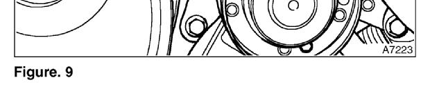
3 Removal B Bank Sensor Assemble 1. Disconnect the battery negative leads. Refer to ASSIST PIN Remove the engine cover. Refer to ASSIST PIN Remove the radiator shell. Refer to ASSIST PIN Remove the dump valve and hoses from B bank. Refer to ASSIST PIN Remove the air box. Refer to ASSIST PIN Remove the front LH undersheet. 7. Drain and retain the engine coolant and remove the engine cooling fan. Refer to ASSIST PIN Drain and retain the coolant from the chargecooler system. Refer to ASSIST PIN Remove the 'B' bank torsion strut and move the secondary expansion tank forwards. Refer to ASSIST PIN Remove the assembly bonnet cross member. Refer to ASSIST PIN Remove the tandem hydraulic pump. Refer to ASSIST PIN Remove the drive belt tensioner. Refer to ASSIST PIN Remove the chargecooler cast air feed pipe from B bank turbo. 14. Remove Primary Expansion Tank mounting screws H. Then manoeuvre to one side. See figure Remove fridge pipe clip retaining bolt J, from inner wing. See figure Disconnect bottom hose connection. 17. Remove HT lead retaining clip K, on chargecooler. See figure Disconnect the coolant inlet pipe L, from the front of the 'B' bank chargecooler. See figure Release the hose clip M, at the bottom of the short hose, on the other end of the coolant inlet pipe. Remove the coolant inlet pipe and hose as an assembly. See figure Remove the bolt N, from the upper bracket on the pump to chargecooler pipe (the bolt also retains the dipstick tube bracket). See figure Remove the screw P, from the 'P' clip, which secures the sensor cable. See figure Remove the bolt Q, from the lower bracket on the pump to chargecooler pipe. This will allow side movement of the pipe, increasing access to the sensor probe. See figure Remove the left-hand chargecooler mounting bolts R, two on
4 the outer side, and one on the inner. See figure Disconnect the hose S, throttle to chargecooler, carefully lever the chargecooler upwards at the centre to allow the sensor removal. See figure Disconnect the electrical connector from the Control Box. 26. Remove the screws from the two 'P' clips, which secures the sensor cable to the rocker cover. 27. Loosen the retaining nut, then carefully pull the sensor probe from the turbocharger flange. Refit: Apply a small amount of anti-seize grease onto the threads of the probe retaining nut. Take care not to bend the probe when fitting into the turbocharger flange and set the probe tube to the vertical position. Make sure that the sensor cable is not twisted and is free from kinks then torque tighten the retaining nut. The remainder of the refit process is the reversal of the removal. On completion of the work a white spot of paint should be applied to the upper fixing bolt head of the Control Box. See Figure 2 item T. Warranty: Procedure Defect Code Repair Code Time Check B Bank S 0.2 Replace A Bank S 0.8 Replace B Bank S 7.8 A Class A or P claim is to be generated upon completion of the work. Individual codes must be entered as separate items and not
5 Parts Information: New Part Number Description PJ109884PB Sensor Assemble A Bank PJ101161PC Sensor Assemble B Bank Displaced Part Number PJ101161PA PJ101161PA Qty One One Torque Specification: Nut-Sensor Probe Nm lbf ft Policy: Service Campaign
6
7


8


9
10


11


12
13


14


15

16 Bentley Bulletins are intended for use by experienced and trained Technicians. If you lack the skills, tools, equipment and a suitable workshop for any procedure described in this document, we suggest you leave such repairs to an Authorised Bentley Dealer or other qualified workshop. See your Bentley Dealer for advise on whether your vehicle may benefit from the information contained within this document. The information contained in the Bentley Bulletin is accurate at the date of publication. However, Bentley Motors regularly updates technical information. Please check with your Bentley Dealer that the Bulletin you intend to use contains the latest available information. Bentley Motors Limited All Rights Reserved
26 - COOLING SYSTEM CONTENTS ENGINE COOLING - DESCRIPTION... 3 ENGINE COOLING - OPERATION... 9 COOLING SYSTEM FAULTS... 1
 26 - COOLING SYSTEM CONTENTS Page LAND ROVER V8 DESCRIPTION AND OPERATION ENGINE COOLING - DESCRIPTION... 3 ENGINE COOLING - OPERATION... 9 FAULT DIAGNOSIS COOLING SYSTEM FAULTS... 1 REPAIR COOLANT - DRAIN
ENGINE - V8. Seal - crankshaft - rear. Refit 1. Ensure both seal location and running surface on crankshaft are clean.
 REPAIRS Seal - crankshaft - rear 1. Ensure both seal location and running surface on crankshaft are clean. 1. Automatic gearbox models: converter drive plate. ENGINE - V8, REPAIRS, Plate - drive - automatic.
Saab 9-5 B205, B Installation instructions MONTERINGSANVISNING INSTALLATION INSTRUCTIONS MONTAGEANLEITUNG INSTRUCTIONS DE MONTAGE.
 SCdefault 9-5 Installation instructions SITdefault Parking heater MONTERINGSANVISNING INSTALLATION INSTRUCTIONS MONTAGEANLEITUNG INSTRUCTIONS DE MONTAGE Accessories Part No. Group Date Instruction Part
SUPERCHARGER. ON-VEHICLE INSPECTION 1. INSPECT SUPERCHARGER OIL LEVEL HINT: With the engine cold, check the oil level on the dipstick.
 EG45 ONVEHICLE INSPECTION 1. INSPECT OIL LEVEL HINT: With the engine cold, check the oil level on the dipstick. (a) Park the vehicle on a level spot and turn the engine off. (b) 4WD: Remove the LH front
Exhaust Gas Recirculation Valve, Replace J S file://c:\program Files\cosids\DATA\TMP\ rtf.html. Remove
 1 Page 1 of 20 Exhaust Gas Recirculation Valve, Replace J982500 Remove 1. Disconnect battery negative lead 2. Disconnect hose (1) from oil filler on air cleaner assembly, then move to one side Release
Publication Number / Title Platform Section Title Change. Removal of DD15 and DD16 Delphi Exhaust Gas Recirculation Valve Actuator
 7 02-15 1 7 02-15 SUBJECT DD15 and DD16 Delphi Exhaust Gas Recirculation Valve Actuator and DD15 and DD16 Sonceboz Exhaust Gas Recirculation Valve Actuator DATE July 2015 Additions, Revisions, or Updates
Cylinder Head, Remove and Install (Z 22 SE)
") Page 1 of 29 Cylinder Head, Remove and Install (Z 22 SE) Remove 1. Open the bonnet. 2. Disconnect the battery. 3. Open the engine cover (1). 4. Detach the engine cover. 6 bolts (2) and (3) 5. Release the
Page 1 of 29 Cylinder Head, Remove and Install (Z 22 SE) Remove 1. Open the bonnet. 2. Disconnect the battery. 3. Open the engine cover (1). 4. Detach the engine cover. 6 bolts (2) and (3) 5. Release the
Service Bulletin 1988 PRELUDE. RECALL: 1988 Prelude Power Steering Supply Hose
 Service Bulletin Model Applicable To File Under Bulletin No. 1988 PRELUDE See VEHICLES AFFECTED ENGINE 88-014 Issue Date APRIL 20, 1988 RECALL: 1988 Prelude Power Steering Supply Hose PROBLEM When subjected
Ford 6.0L. Part #: Part #: BD GASKET PART# will be needed for this installation.
 1 BD EGR COOLER 2003-2007 Ford 6.0L Part #: 1090201 Part #: 1090202 PLEASE READ ALL INSTRUCTIONS BEFORE INSTALLATION BD GASKET PART# 1090002 will be needed for this installation. 2 K I T C O N T E N T
Tech Talk. Timing Belt 6VD1/6VE1
 Holden DOHC V6 Frontera 6VD1 3.2L 1999 2004 Jackaroo 6VE1 3.5L 1998 2004 Rodeo TF 6VD1 3.2L 1998 2003 Rodeo RA 6VE1 3.5L 2003 2005 Important: Read through all the instructions before proceeding with the
EGR Actuator May Description and Operation of the DD13 Exhaust Gas Recirculation Valve Actuator
 5 17-13 1 5 17-13 SUBJECT DATE EGR Actuator May 2013 Additions, Revisions, or Updates Publication Number / Title Platform Section Title Change Description and Operation of the DD13 Exhaust Gas Recirculation
Engine Remove and Install ( ) Remove. Section Title. Special Tools. Workshop Equipment Trolley jack A Engine lifting tackle
 Remove. Section Title. Special Tools. Workshop Equipment Trolley jack A Engine lifting tackle") Engine Remove and Install ( 4 0) Special Tools 068A 068A0-068A Engine lifting tackle -068A-0 Lifting eyebolts Workshop Equipment Trolley jack Materials High-temperature grease ESDM-C0-A Proprietary Tools
Engine Remove and Install ( 4 0) Special Tools 068A 068A0-068A Engine lifting tackle -068A-0 Lifting eyebolts Workshop Equipment Trolley jack Materials High-temperature grease ESDM-C0-A Proprietary Tools
EG-34 ENGINE MECHANICAL TIMING BELT COMPONENTS FOR REMOVAL AND INSTALLATION
 EG34 TIMING BELT COMPONENTS FOR REMOVAL AND INSTALLATION EG35 TIMING BELT REMOVAL (See Components for Removal and Installation) 1. DISCONNECT NEGATIVE TERMINAL CABLE FROM BATTERY CAUTION: Work must be
Fitting Instructions: Rocket III / Classic / Roadster A and A Heated Grips Kit
 A96804 and A96805 - Heated Grips Kit Always have Triumph approved parts, accessories and conversions fitted by a trained technician of an authorised Triumph Dealer. The fitment of parts, accessories and
REMOVAL AND INSTALLATION
 303-08-1 Engine Emission Control 303-08-1 REMOVAL AND INSTALLATION Exhaust Gas Recirculation (EGR) Cooler 6.4L Diesel, Vertical Cooler Item Part Number Description 1 Fuel cooler tube 2 W701317 Power steering
English. 1 of 5. Parts Supplied:
 English Fitting Instructions: Daytona 675, Street Triple, Street Triple R, Tiger 800 and Tiger 800XC A96809 - Daytona 675 up to VIN 874, Street Triple and Street Triple R (79 kw models only) A96807 - Daytona
TECHNICAL BULLETIN 303-S498. V8 XJ Series/XK. Engine Fail Safe Displayed Replace Throttle Body Normally Aspirated Vehicles Only Service Action S498
 SERVICE V8 XJ Series/XK DATE 2/02 Amended 07/03 TECHNICAL BULLETIN Engine Fail Safe Displayed Replace Throttle Body Normally Aspirated Vehicles Only Service Action S498 Remove and destroy Bulletin 303-S498,
Camshaft - Remove and Install ( )
") «Escort 1991/1996 Table of Contents» «Group 21: Basic Engine» «Section 21-09: 2.0l DOHC 16V Engine» «REMOVAL AND INSTALLATION» Camshaft - Remove and Install (21 283 0) Special Tools 15-030 AUniversal flange
«Escort 1991/1996 Table of Contents» «Group 21: Basic Engine» «Section 21-09: 2.0l DOHC 16V Engine» «REMOVAL AND INSTALLATION» Camshaft - Remove and Install (21 283 0) Special Tools 15-030 AUniversal flange
COOLING SYSTEM - V8. Cooling system component layout DESCRIPTION AND OPERATION
 Cooling system component layout 26-2-2 DESCRIPTION AND OPERATION 1 Heater matrix 2 Heater return hose 3 Heater inlet hose 4 Heater inlet pipe 5 Throttle housing 6 Connecting hose 7 Throttle housing inlet
PowerMax Diesel Upgrade For Cummins Engines
 PowerMax Diesel Upgrade For Cummins Engines 00.5-007.5 Dodge Ram With Cummins 5.9L Item 3 4 5 6 7 8 9 0 3 4 5 6 7 8 Parts List Description Turbocharger Ancillary kit 773069- (includes) Installation Instructions
ENGINE ASSEMBLY. COMPONENTS (Part 1)
") 1 of 32 ENGINE ASSEMBLY COMPONENTS (Part 1) 2 of 32 COMPONENTS (Part 2) 3 of 32 COMPONENTS (Part 3) 4 of 32 COMPONENTS (Part 4) 5 of 32 COMPONENTS (Part 5) 6 of 32 COMPONENTS (Part 6) 7 of 32 COMPONENTS
1 of 32 ENGINE ASSEMBLY COMPONENTS (Part 1) 2 of 32 COMPONENTS (Part 2) 3 of 32 COMPONENTS (Part 3) 4 of 32 COMPONENTS (Part 4) 5 of 32 COMPONENTS (Part 5) 6 of 32 COMPONENTS (Part 6) 7 of 32 COMPONENTS
TECHNICAL BULLETIN Engine Vibration/Noise Above 1000 RPM Oil Pump Resonance Install Revised Oil Pump SERVICE DATE MODEL 2002 MY.
 SERVICE V8 XJ Series DATE 12/02 TECHNICAL BULLETIN Engine Vibration/Noise Above 1000 RPM Oil Pump Resonance Install Revised Oil Pump 100-21 MODEL 2002 MY V8 XJ Series VIN F44114 - F55936 Issue: Some 2002
This information covers the proper replacement procedure for the EGR valve on the Volvo D16F engine.
 Volvo Trucks North America Greensboro, NC USA EGR Valve, Replacement DService Bulletin Trucks Date Group No. Page 11.2006 254 24 1(17) EGR Valve Replacement D16F W2005772 This information covers the proper
Emissions - Refuel Vapor Control Valve Damaged/MIL ON Section Title: Engine TSB No. TS R
 1999 Suzuki Esteem GL Sedan L4-1.8L Page 1 Technical Service Bulletin # TS02R Date: 020308 Emissions - Refuel Vapor Control Valve Damaged/MIL ON Section Title: Engine TSB No. TS 02 03082R Division: Automotive
Fuel and exhaust systems 4A 21
 Fuel and exhaust systems 4A 21 15.40 Unscrew the union nuts and disconnect the fuel feed and return hoses from the manifold 41 Disconnect the injector wiring harness connector and the vacuum hose from
XRT300 AND XRT350 BA XR6 TURBO UPGRADE KIT FITTING INSTRUCTIONS
 XRT300 AND XRT350 BA XR6 TURBO UPGRADE KIT FITTING INSTRUCTIONS The use of NFU (No Further use) and REUSE (Re Use) relates to the individual parts storage when performing the upgrade. Also note that all
SCdefault. 900 Installation instructions
 SCdefault 900 Installation instructions SITdefault Engine block heater MONTERINGSANVISNING INSTALLATION INSTRUCTIONS MONTAGEANLEITUNG INSTRUCTIONS DE MONTAGE Accessories Part No. Group Date Instruction
This kit may void factory warranty please check with manufacturer.
 Thank you for purchasing a Sinister Manufacturing Company EGR delete kit. Precision manufactured using aircraft quality 304 stainless steel and billet aluminum; this EGR kit is designed to endure years
HYDRAULICS. TX420 & & lower. Hydraulic Tandem Pump Removal. 4. Remove the LH side panel (Fig. 0388).
.") TX420 & 425 240000299 & lower 4. Remove the LH side panel (Fig. 0388). Hydraulic Tandem Pump Removal Note: Cleanliness is a key factor in a successful repair of any hydraulic system. Thoroughly clean all
TX420 & 425 240000299 & lower 4. Remove the LH side panel (Fig. 0388). Hydraulic Tandem Pump Removal Note: Cleanliness is a key factor in a successful repair of any hydraulic system. Thoroughly clean all
1991 Volkswagen Vanagon Syncro
 corner of radiator. See Fig. 1. Fig. 1: Bleeding Cooling System 2. Open bleeder valve in engine compartment (turn counterclockwise). See Fig. 1. Fill expansion tank until full. Start and run engine at
PARTIAL ENGINE ASSY (2TR FE)
") COMPONENTS 147 1421Z01 Clip Hood Subassy x9 Radiator Support to Frame Seal LH 30 (306, 22) 30 (306, 22) Fan and Generator V Belt 5.0 (51, 44 in. lbf) Fan Shroud Fan Pulley Fan w/ Fluid Coupling PRE RUNNER
COMPONENTS 147 1421Z01 Clip Hood Subassy x9 Radiator Support to Frame Seal LH 30 (306, 22) 30 (306, 22) Fan and Generator V Belt 5.0 (51, 44 in. lbf) Fan Shroud Fan Pulley Fan w/ Fluid Coupling PRE RUNNER
Mazda North American Operations Irvine, CA
 Service Bulletin Mazda North American Operations Irvine, CA 92618-2922 Subject: MIL ON - P2070 SET Bulletin No: 01-019/08 2004-2007 RX-8 - MIL ON - P2070 SET BULLETIN NOTE This bulletin supersedes the
WARNING: ALWAYS relieve fuel pressure before disconnecting any fuel related component. DO NOT allow fuel to contact engine or electrical components.
 4.0L V8 - VINS [K,U] Selected Block 1990 Lexus LS 400 For Lextreme Powertrain 2020 S. Hacienda Blvd. # D Hacienda Heights California 91745 Copyright 1998 Mitchell Repair Information Company, LLC Friday,
Vehicle Level Engine, Cooling and Exhaust Engine Cylinder Head Assembly Service and Repair. Service and Repair
 Page 1 of 7 Home Account Contact ALLDATA Log Out Help BILL SEIDLES MITSUBISHI Select Vehicle New TSBs Technician's Reference Component Search: OK 2001 Pontiac Sunfire L4-2.2L VIN 4 Conversion Calculator
SECTION 6A1-2 - ENGINE MECHANICAL - V6 SUPERCHARGED
 SECTION 6A1-2 - ENGINE MECHANICAL - V6 SUPERCHARGED CAUTION: This vehicle will be equipped with a Supplemental Restraint System (SRS). A SRS will consist of either seat belt pre-tensioners and a driver
Installation Manual v1.0: Twin CP3 Fuel Injection Kit Dodge 5.9L
 Installation Manual v1.0: Twin CP3 Fuel Injection Kit 2004.5-2007 Dodge 5.9L Figure 1 - Full Kit Photo 25 Figure 2 - Hardware Kit Please read all instructions before installation. This kit is not emissions
1 of 8 1/17/2017 8:18 AM
 Timing Belt Service and Repair, Removal and Replacement: Replacing... http://repair.alldata.com/alldata/article/display.action?componentid=64&... 1 of 8 1/17/2017 8:18 AM Replacing the timing belt Special
ENGINE REMOVAL & INSTALLATION
 TORQUE VALUES ENGINE MOUNTING = Apply Victory All Purpose Grease 2872187 1. Install all bolts in order A-H Do not tighten. E 41 Nm (30 lb-ft) M8 x 25mm D 111 Nm (82 lb-ft) 12 x 100mm ENGINE INSTALLATION
Accessory Fitting Instructions
 Accessory Fitting Instructions Kit Number Models Affected A9689 Thruxton 00 A96808 Thruxton 00 R Low Handlebar Kit Front Fairing Kit Kit Number Models Affected A97080 Thruxton 00 A97084 Thruxton 00 R Note:
Pistons and Connecting Rods, Remove and Install
 Page 1 of 46 Pistons and Connecting Rods, Remove and Install Remove 1. Open the bonnet. 2. Disconnect the battery. 3. Open the engine cover (1). 4. Detach the engine cover. 6 bolts (2) and (3) 5. Release
REMOVAL. Fig Sized for Print
 ALLDATA Online - 2000 Dodge Truck Grand Caravan FWD V6-3.3L VIN R - Intake M... Page 1 of 10 REMOVAL 1. Remove windshield wiper module. 2. Perform fuel system pressure release procedure (before attempting
Bulb Renewal TOP ACCESS COVER
 TOP ACCESS COVER To gain access to the headlight units, the top cover must be removed. Unscrew and remove the six fasteners (A). Remove the top cover. After changing the defective bulb, refit the cover,
INSTALLATION INSTRUCTIONS
 INSTALLATION INSTRUCTIONS Accessory Application Publications No. ENGINE BLOCK P/N 08T44-SJA-200 2008 FIT AII 37494 Issue Date JUL 2007 PARTS LIST Engine block heater Aluminum washer Heater harness Protective
OIL PUMP (for 4WD and Pre-Runner)
") 1GR-FE BRICATION OIL PUMP (for 4WD and Pre-Runner) OIL PUMP (for 4WD and Pre-Runner) ENGINE 1GR-FE BRICATION COMPONENTS 23 88 (897, 65) 88 (897, 65) NO. 1 ENGINE UNDER COVER SUB-ASSEMBLY FRONT PROPELLER
1GR-FE BRICATION OIL PUMP (for 4WD and Pre-Runner) OIL PUMP (for 4WD and Pre-Runner) ENGINE 1GR-FE BRICATION COMPONENTS 23 88 (897, 65) 88 (897, 65) NO. 1 ENGINE UNDER COVER SUB-ASSEMBLY FRONT PROPELLER
MAZDA 3 MPS FRONT MOUNTING INTERCOOLER INSTALLATION
 MAZDA 3 MPS FRONT MOUNTING INTERCOOLER INSTALLATION Tools needed: 7mm Hose clamp driver 10mm,12mm sockets and suitable ratchet with extensions Flat bladed screwdriver Pliers Phillips screwdriver KIT CONTENTS
EG-37 ENGINE MECHANICAL TIMING BELT COMPONENTS FOR REMOVAL AND INSTALLATION 2JZ-GE
 ENGINE EG37 TIMING BELT COMPONENTS FOR REMOVAL AND INSTALLATION 2JZGE EG38 ENGINE 2JZ GTE ENGINE EG39 TIMING BELT REMOVAL (See Components for Removal and Installation) 1. REMOVE BATTERY AND BATTERY TRAY
1998 Saab 900 SE ENGINES Saab 2.0L & 2.3L 4-Cylinder
 Removal & Installation See VALVE SPRINGS under CYLINDER HEAD under OVERHAUL. CAMSHAFT Removal 1. Rotate crankshaft until "0" mark on flywheel aligns with timing mark on flywheel cover. Remove inspection
XDP Complete EGR Race Track Kit w/up-pipe. Item Number: XD144
 XDP Complete EGR Race Track Kit w/up-pipe Item Number: XD144 PACKING LIST: 2 - Lined 3/4" SS Hose Clamp 1-3/4 Silicone Hose 1 - XDP Engraved EGR Valve Block-Off Plate with O-ring 1 - EGR Cooler Block-Off
EGR Actuator Slow Learn April Installation of the DD13 Exhaust Gas Recirculation Valve Actuator Pull Rod
 1 4 07-13 SUBJECT DATE EGR Actuator Slow Learn April 2013 Additions, Revisions, or Updates Publication Number / Title Platform Section Title Change DDC-SVC-MAN-0083 Installation of the DD13 Exhaust Gas
CUSTOM-DIESEL.COM ATTENTION VERY IMPORTANT - PLEASE READ
 ATTENTION VERY IMPORTANT - PLEASE READ IF YOU PURCHASED THIS ITEM FROM EBAY, WE WANT YOU TO KNOW THAT EBAY HAS ALWAYS GIVEN YOU, THE BUYER, THE STRENGTH TO VOICE YOUR OPINION OF EBAY SELLERS BY LEAVING
Engine and A4LDE Automatic Transmission Remove and Install ( ) Remove
 Remove") Engine and A4LDE Automatic Transmission Remove and Install ( 3 0) Special Tools 068A -068A Engine lifting bracket -540 Bolt tightening angle gauge Workshop Equipment Transmission jack Workshop crane Assembly
Engine and A4LDE Automatic Transmission Remove and Install ( 3 0) Special Tools 068A -068A Engine lifting bracket -540 Bolt tightening angle gauge Workshop Equipment Transmission jack Workshop crane Assembly
Lower Intake Manifold Replacement
 Lower Intake Manifold Replacement Removal Procedure 1. Turn OFF all the lamps and the accessories. 2. Ensure the ignition switch is in the OFF position. 3. Disconnect the negative battery cable from the
Please call us at Mon-Fri 8am-5pm if you need any additional assistance.
 TM Upgraded 6.0L EGR Cooler R Thank you for purchasing a Sinister Diesel Upgraded EGR Cooler. This EGR cooler is designed to endure years of heavy use.these installation instructions have been written
EG 18 ENGINE MECHANICAL TIMING BELT EG5EK 01 COMPONENTS FOR REMOVAL AND INSTALLATION
 EG18 ENGINE TIMING BELT COMPONENTS FOR REMOVAL AND INSTALLATION EG5EK01 ENGINE EG19 EG20 ENGINE ENGINE EG21 EG22 ENGINE TIMING BELT REMOVAL EG5G101 1. REMOVE OIL PAN PROTECTOR 2. REMOVE ENGINE UNDER COVER
Cylinder Heads Remove and Install (all) ( ) Remove. 2,5l TCI Diesel Engine. Special Tools Bolt tightening angle gauge
 ( ) Remove. 2,5l TCI Diesel Engine. Special Tools Bolt tightening angle gauge") Cylinder Heads Remove and Install (all) ( 64 0) Special Tools 00 00 00 Splined head socket, cylinder head bolts 00 Cylinder head locating studs 540 04 540 Bolt tightening angle gauge 04 Wrench for injectors
Cylinder Heads Remove and Install (all) ( 64 0) Special Tools 00 00 00 Splined head socket, cylinder head bolts 00 Cylinder head locating studs 540 04 540 Bolt tightening angle gauge 04 Wrench for injectors
Installation Instructions
 BD DODGE CUMMINS PERFORMANCE E X H A U S T M A N I F O L D Installation Instructions Application List 2007-2015 6.7L / HE351 OE Turbo 1045965 2007-2015 6.7L / T4 S400 Turbo s 1045965-T4 PLEASE READ ALL
TECHNICAL INSTRUCTIONS FOR LIMITED SERVICE CAMPAIGN (LSC) A0N HV WATER PUMP REPLACEMENT MODEL YEAR PRIUS
 A0N HV WATER PUMP REPLACEMENT MODEL YEAR PRIUS") TECHNICAL INSTRUCTIONS FOR LIMITED SERVICE CAMPAIGN (LSC) A0N HV WATER PUMP REPLACEMENT 2004 2007 MODEL YEAR PRIUS I. OPERATION FLOWCHART II. IDENTIFICATION OF AFFECTED VEHICLES A. AFFECTED VIN RANGE Model
TECHNICAL INSTRUCTIONS FOR LIMITED SERVICE CAMPAIGN (LSC) A0N HV WATER PUMP REPLACEMENT 2004 2007 MODEL YEAR PRIUS I. OPERATION FLOWCHART II. IDENTIFICATION OF AFFECTED VEHICLES A. AFFECTED VIN RANGE Model
TOYOTA HILUX Suspension Installation Instructions. NOTE: Occupational Health & Safety procedures must be observed at all times.
 INSTALLATION GUIDE TOYOTA HILUX 2015+ Suspension Installation Instructions NOTE: Occupational Health & Safety procedures must be observed at all times. IMPORTANT: Installations should only be done by a
Installation Manual v2.2: Twin CP3 Fuel Injection Kit Dodge 5.9L
 12/13/11 ATS Twin CP3 Kit 701-900-2272-INST Installation Manual v2.2: Twin CP3 Fuel Injection Kit 2003-2004 Dodge 5.9L Figure 1 - Full Kit Photo 26 Figure 2 - Hardware Kit 1 Please read all instructions
* PLEASE READ INSTRUCTIONS PRIOR TO INSTALLATION
 XDP 6.0L Complete EGR Delete Kit w/up-pipe Item Number: XD169 PACKING LIST: 2 - Lined 3/4" Hose Clamps, 1-180 Coolant Tube, 1-3/4 Silicone Hose, 1 - Stainless Steel Up-pipe 1 - EGR Valve Block-Off Plate,
Accessory Fitting Instructions
 Accessory Fitting Instructions Engine Bars Kit Number A978800 A978807 Models Affected Tiger Explorer, Tiger Explorer XC, Explorer XR, Explorer XRX, Explorer XC, Tiger Explorer, Tiger Explorer XC, Explorer
Bulb Renewal OVERVIEW
 Bulb Renewal OVERVIEW It is important that only Jaguar bulbs of the type specified are used when renewing bulbs. Before renewing bulbs, switch off the ignition and light switches. Top cover To gain access
Timing Chain - Renew ( )
") «Escort 1991/1996 Table of Contents» «Group 21: Basic Engine» «Section 21-09: 2.0l DOHC 16V Engine» «REMOVAL AND INSTALLATION» Timing Chain - Renew (21 314 0) Special Tools 15-030 AUniversal flange holding
«Escort 1991/1996 Table of Contents» «Group 21: Basic Engine» «Section 21-09: 2.0l DOHC 16V Engine» «REMOVAL AND INSTALLATION» Timing Chain - Renew (21 314 0) Special Tools 15-030 AUniversal flange holding
Preventive maintenance 4
 00 Series Preventive maintenance Preventive maintenance periods Use the procedures in this chapter to maintain your engine in accordance with the preventive maintenance schedule. Check the periods given
Powerstroke 6.4L EGR Block Kit
 Read instructions thoroughly before proceeding! ***This kit may void factory warranty please check with manufacturer.*** You will need the following tools for this installation: 10mm wrench 13mm wrench
1997 Volvo 850 GLT. Fig. 2: Removing Drive Shaft, Engine Mount Bolt & Torque Arm (5-Cylinder) Courtesy of VOLVO CARS OF NORTH AMERICA.
 Courtesy of VOLVO CARS OF NORTH AMERICA.") Fig. 2: Removing Drive Shaft, Engine Mount Bolt & Torque Arm (5-Cylinder) 4. Remove front exhaust pipe nuts and springs. Remove front exhaust pipe bolts. Disconnect speedometer. Remove engine mounting
Fig. 2: Removing Drive Shaft, Engine Mount Bolt & Torque Arm (5-Cylinder) 4. Remove front exhaust pipe nuts and springs. Remove front exhaust pipe bolts. Disconnect speedometer. Remove engine mounting
Part number SP Honda Element 2.4L, 4 cyl.
 Part number SP1727 07-08 Honda Element 2.4L, 4 cyl. 1-2 piece cold air intake 1-3 Injen filter (#1017) 1-2.75 straight hose (#3043) 1-3 straight hose (#3044) 1-12 8mm vacuum hose (#3091) 2- Power Bands.312.040
Mazda North American Operations Irvine, CA
 Service Bulletin Mazda North American Operations Irvine, CA 92618-2922 Subject: MILKY SUBSTANCE ON OIL LEVEL GAUGE (DIPSTICK) Bulletin No: 01-050/06 2004-2005 RX-8 - MILKY SUBSTANCE ON OIL LEVEL GAUGE
Removing and installing toothed belt
 Page 1 of 10 Special tools and workshop equipment required Diesel injection pump locking pin -3359- (2x) Pin wrench -T10020- Crankshaft stop -T10050- for engines with circular crankshaft sprocket Locking
Cylinder head/gasket, replacing
 1(16) Cylinder head/gasket, replacing Special tools: 951 2666, 951 2767, 999 5450, 999 5452, 999 5454, 999 5670, 999 5718, 999 5719, 999 5750, 999 5972 Removing the cylinder head gasket Note! As the illustrations
CAUTION: Do not compress the ratchet assembly. This will damage the ratchet assembly.
 Installation Engines with ratcheting timing chain tensioners 1. CAUTION: Timing chain procedure must be followed exactly or damage to valves and pistons will result. CAUTION: Do not compress the ratchet
Recall - Fuel Cross-Flow Extended Coverage 01M05 OWNER NOTIFICATION PROGRAM
 Technical Service Bulletin # 01M05 Recall - Fuel Cross-Flow Extended Coverage 01M05 OWNER NOTIFICATION PROGRAM All 1990, 1991, 1992 and 1993 Model Year F-Series Vehicles equipped with Dual Fuel Tanks and
FULL BORE PERFORMANCE EXHAUST MANIFOLDS F-150 ECOBOOST 3.5L
 2018-01-15 FORD F150 ECOBOOST 3.5L FULL BORE PERFORMANCE MANIFOLD SET (PART #500101X) 1 FULL BORE PERFORMANCE EXHAUST MANIFOLDS F-150 ECOBOOST 3.5L INSTALLATION INSTRUCTIONS 2011-2012 FORD F150 3.5L ECOBOOST
Fitting Instructions: Tiger 800 and Tiger 800XC A and A to VIN and from VIN to VIN A
 English Fitting Instructions: Tiger 800 and Tiger 800XC A98800 and A9880 to VIN 64 and from VIN 69457 to VIN 607 A98807 Thank you for choosing this Triumph genuine accessory kit. This accessory kit is
English. Fitting Instructions: Street Triple Rx, Street Triple from VIN and Street Triple R from VIN A , A and A
 English Fitting Instructions: Street Triple Rx, Street Triple from VIN 560477 and Street Triple R from VIN 560477 A968090, A968 and A9687 Thank you for choosing this Triumph genuine accessory kit. This
IN-VEHICLE REPAIR. Upper Intake Manifold
 303-01-1 Engine 3.9L and 4.2L 303-01-1 IN-VEHICLE REPAIR Upper Intake Manifold Special Tool(s) Remover, Spark Plug Wire 303-106 (T74P-6666-A) Material Item Silicone Brake Caliper Grease and Dielectric
(WK) Jeep Grand Cherokee (WD) Dodge Durango
 Jeep Grand Cherokee (WD) Dodge Durango") Dealer Service Instructions for: Safety Recall S16 Left Front Brake Caliper Revised May 2016 Models NOTE: The wheel lug nut torque specification has been updated. 2015-2016 (WK) Jeep Grand Cherokee (WD)
Dealer Service Instructions for: Safety Recall S16 Left Front Brake Caliper Revised May 2016 Models NOTE: The wheel lug nut torque specification has been updated. 2015-2016 (WK) Jeep Grand Cherokee (WD)
Gearbox sectional drawing
 Gearbox sectional drawing BMW Grafik Design MT- KL39000 3.5 3.6 3 4 77 3 4 77 3473 3 4 7 3 4 7 3 4 73 KL300 Replacing the shaft sealing rings in the gearbox housing and gearbox cover All shaft sealing
14A6816H190 GT-2150 (2003) Page 1 of 28 Carburetor
 Page 1 of 28 Carburetor") 14A6816H190 GT-2150 (2003) Page 1 of 28 Carburetor 14A6816H190 GT-2150 (2003) Page 2 of 28 Carburetor TC-640221 1 /P Carburetor (Incl 184 of Engine Parts Lists) 1 TC-640216 1 Throttle Shaft & Lever Assembly
14A6816H190 GT-2150 (2003) Page 1 of 28 Carburetor 14A6816H190 GT-2150 (2003) Page 2 of 28 Carburetor TC-640221 1 /P Carburetor (Incl 184 of Engine Parts Lists) 1 TC-640216 1 Throttle Shaft & Lever Assembly
REMOVAL. 5. REMOVE OIL DIPSTICK GUIDE (a) Remove the bolt, dipstick guide and engine wire bracket. (b) Remove the O ring from the dipstick guide.
 Remove the bolt, dipstick guide and engine wire bracket. (b) Remove the O ring from the dipstick guide.") EM34 ENGINE MECHANICAL (2RZFE, 3RZFE) P23426 EM1MY01 REMOVAL 1. DRAIN ENGINE COOLANT 2. DISCONNECT THESE CABLES: (a) Disconnect the accelerator cable from the throttle body. A/T: Disconnect the throttle
EM34 ENGINE MECHANICAL (2RZFE, 3RZFE) P23426 EM1MY01 REMOVAL 1. DRAIN ENGINE COOLANT 2. DISCONNECT THESE CABLES: (a) Disconnect the accelerator cable from the throttle body. A/T: Disconnect the throttle
Drawing A Crankcase, Cylinder
 Drawing A Crankcase, Cylinder 1 Drawing A Crankcase, Cylinder Reference Item number Qty Description 1 4241 021 0300 1 Crankcase 2 9639 003 1230 2 Oil seal 12x22x7 3 9523 003 0000 2 Grooved ball bearing
Turbo Upgrade Kit Installation for Ford F-150 PN s , ,
 Turbo Upgrade Kit Installation for Ford F-150 PN s 251004, 251005, 251006 BORLA PERFORMANCE INDUSTRIES ***** Please compare the parts in the box with the bill of materials provided ***** to assure that
Service Bulletin
 Service Bulletin 17-090 November 10, 2017 07659 Version 1 Product Update: 2018 Odyssey Rear Power Window Switches AFFECTED VEHICLES Year Model Trim VIN Range 2018 Odyssey ALL except LX Check the in VIN
Coolant Pump, Remove and Install (Z 22 SE)
") Page 1 of 10 Coolant Pump, Remove and Install (Z 22 SE) Remove 1. Open the bonnet. 2. Disconnect the battery. 3. Open the rear engine cover (1). 4. Detach the rear engine cover. 6 bolts (2) and (3) 5.
Page 1 of 10 Coolant Pump, Remove and Install (Z 22 SE) Remove 1. Open the bonnet. 2. Disconnect the battery. 3. Open the rear engine cover (1). 4. Detach the rear engine cover. 6 bolts (2) and (3) 5.
1995 Mitsubishi Montero LS. Ensure timing marks are aligned. Mark timing belt direction of rotation.
 TIMING BELT NOTE: Ensure timing marks are aligned. Mark timing belt direction of rotation. Removal 1. Disconnect negative battery cable. Drain engine coolant. Remove engine coolant reservoir tank, fan
SUSPENSION - FRONT Toyota Celica DESCRIPTION ADJUSTMENTS & INSPECTION WHEEL ALIGNMENT SPECIFICATIONS & PROCEDURES WHEEL BEARING
 SUSPENSION - FRONT 1988 Toyota Celica FRONT SUSPENSION Toyota DESCRIPTION Vehicles are equipped with front wheel drive and independent MacPherson strut front suspension. Suspension consists of vertically
mk3 SEAT Ibiza Cupra Front Mount Intercooler.
 mk3 SEAT Ibiza Cupra Front Mount Intercooler. Warning be sure not to let any foreign body enter the inlet track of the vehicle whilst the following work is being carried out. Serious engine damage may
Under CORRECTIVE ACTION and PARTS INFORMATION, ZDX was added.
 2008 Acura TL 3.2L Eng Base DRIVE BELT SQUEAKS TECHNICAL SERVICE BULLETIN Reference Number(s): 10-035, Date of Issue: July 24, 2012 ACURA: 2007-12 MDX; 2007-08 TL; 2010-12 ZDX CATEGORY: Engine APPLIES
Accessory Fitting Instructions
 Accessory Fitting Instructions Heated Grip Kit Kit Number Models Affected A9680 Street Twin, Street Cup from VIN 8750 A9680 Street Cup to VIN 879 A9685 Street Scrambler A9685 Thruxton 00 R A9689 Thruxton
SECTION D REAR SUSPENSION. Section Description Page D.1. REMOVING AND REFITTING A REAR SUSPENSION UNIT 5
 SECTION D REAR SUSPENSION Section Description Page D.1. REMOVING AND REFITTING A REAR SUSPENSION UNIT 5 D.2. REMOVING AND REFITTING THE COMPONENTS OF THE REAR SUSPENSION 8 D.3. CHECKING AND OVERHAULING
This information covers procedures for replacing the sealant for the crankshaft cover on the Volvo D16F engine.
 Volvo Trucks North America Greensboro, NC USA DService Bulletin Trucks Date Group No. Page 1.2008 216 50 1(17) Sealant Crankshaft Cover, Replacement D16F Sealant Crankshaft Cover, Replacement W2005773
TIMING BELT COMPONENTS EM 15
 ENGINE MECHANICAL COMPONENTS EM15 EM16 ENGINE MECHANICAL COMPONENTS (Cont d) ENGINE MECHANICAL EM17 REMOVAL OF (See pages EM15 and 16) 1. DISCONNECT CABLE FROM NEGATIVE TERMINAL OF BATTERY CAUTION: Work
Body, front. Lock carrier with attachments, removing and installing
 Page 1 of 19 50-1 Body, front Lock carrier with attachments, removing and installing 1 - Hex bolt (6x) 45 Nm (33 ft lb) 2 - Hex bolt 45 Nm (33 ft lb) 3 - Hex bolt (4x) 10 Nm (7 ft lb) 4 - Hex bolts (2x)
Includes: 1. J-hook Block Off / Coolant Reroute 1. Coolant Hose 1. Turbocharger Up Pipe Block Off Disc 2. Hose clamps
 Includes: 1. J-hook Block Off / Coolant Reroute 1. Coolant Hose 1. Turbocharger Up Pipe Block Off Disc 2. Hose clamps WARNING: This product is not legal for sale or use on pollution controlled vehicles
TECHNICAL BULLETIN No:
 CIRCULATE: TO TECHNICAL BULLETIN No: Date: 14 Mar 2006 Service Mgr Warranty Workshop Body Shop Parts X X X X X SECTION: 501-01 Passenger Compartment Water Ingress AFFECTED VEHICLE RANGE: Land Rover LR3
1992 Toyota Cressida
 Monday, May 16, 2016 5:32:47 PM Page 13 2005 Mitchell Repair Information Company, LLC. Fig. 7: Exploded View Of Typical Cylinder Head & Components Fig. 8: Cylinder Head Bolt Removal Sequence Monday, May
2/18/2017 Cylinder Head Assembly Service and Repair, Removal and Replacement: Cylinder Head
 Cylinder Head http://repair.alldata.com/alldata/article/display.action?componentid=65&itypeid=401&nonstandardid=2762152&vehicleid=47645&miles=&printfriendl 1/17 RH Splash Shield Accessory Drive Belt, Thermostat
AJV8 Engine Assembly. AJV8 Engine Assembly
 AJV8 Engine Assembly Contents Cylinder Block Dowels, Plugs and Pipes 2 4 Crankshaft Bearing and Cylinder Bore Dimensions 5 9 Bearing Measuring 6 Engine Dimensions and Codes 6 7 Main Bearing Selection Chart
Cooling system components, removing and installing
 Page 1 of 40 19-1 Cooling system components, removing and installing WARNING! The cooling system is pressurized when the engine is warm. When opening the expansion tank, wear gloves and other appropriate
16A. STARTING - CHARGING Starter: Removal - Refitting REFITTING 16A-11 K4M II - REMOVAL OPERATION III - FINAL OPERATION
 STARTING - CHARGING Starter: Removal - Refitting 16A K4M II - REMOVAL OPERATION III - FINAL OPERATION JR5 a Clip: -the gearbox control cable sleeve stops on the gearbox, - the control cables onto the gearbox.