CRUSH HAZARD: CHILD SAFETY HAZARD:
|
|
|
- Joseph Cole
- 5 years ago
- Views:
Transcription


1 1
2 This Operations Manual contains important instructions, warnings, and safety procedures that must be understood BEFORE assembling or using the M.I.N.E. Trapping System. Failure to review and understand the ENTIRE MANUAL prior to assembly or use could result in serious injury or death to you or someone else. CRUSH HAZARD: This device uses a wireless transmitter to remotely trigger a HEAVY DROP GATE, which can cause serious injury or death. ALWAYS secure the drop gate with the Gate Safety Clip before conducting any work on or around the gate. ALWAYS ensure that gate area is clear BEFORE pushing the transmitter button, connecting wires inside the control box, or replacing the transmitter battery. CHILD SAFETY HAZARD: This product can cause serious injury or death. Keep children away from equipment at all times. At least TWO PEOPLE are required to assemble and install the M.I.N.E. Trapping System. Assembly and installation without the assistance of another person may result in injury. ALWAYS wear appropriate protective equipment when applicable, including eye and ear protection. ALWAYS disconnect battery from control box when trapping system is not in use. Reciever is constantly in use and will drain the battery. NEVER transport M.I.N.E. Gate with the battery inside the control box. Transporting the gate with battery installed will cause severe and permanent damage to both the battery and the control box electronics. Keep control box clean and protected from moisture in order to prevent damage and to ensure proper operation of the trapping system. 2


3 Important Safety Information...2 Equipment Inventory and Identification...4 Installation Tools and Supplies...5 Material List of Equipment Not Included...6 Adjusting Trigger Assembly...7 Installing Connecting Rod and Clevis...8 Installing Control Box...9 Attaching Connecting Rod to Latch...10 Mounting Antenna to Control Box...11 Building the Enclosure...12 Installing M.I.N.E. Post Clips...12 Installing M.I.N.E. Gate...13 Installing Panels and Posts...14 Installing Rigid Panels...16 Installing T-Post Camera Mount...17 Mounting Booster Antenna...18 Testing Gate Operation...19 Feeder Modifications...20 Replacing Long Range Transmitter Battery...21 Warranty


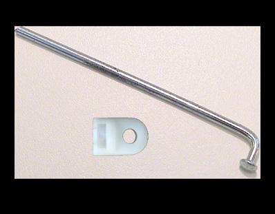


4 Gate with Frame Trigger Assembly Control Box Receiver Self Tapping Screws Connecting Rod & Clevis Rod Adapter Long Range Transmitter 12 volt Battery Safety Pin Antenna Tube 4


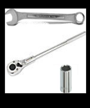


5 Drill Mini Bolt Cutter Pliers 11 Gauge Steel Galvanized Wire 20 Tape Measure 3/8 Nut Driver Hand Pick T-Post Driver 1/2 Socket with Wrench 9/16 Wrench Screwdriver 3/32 Allen Wrench Multi-meter 8 Zip Ties Shovel T-Post Puller 5


6 Items available for purchase from JAGER PRO authorized distributors 16 ft Flex Panels (6 ea) 8 ft Rigid Panels (12 ea) Feeder with Dinnerbell and Digital Timer M.I.N.E. Post Clips M.I.N.E. Clip Socket 7ft. T-Posts (24 ea) M.I.N.E. Camera I.C.E. Camera Booster Antenna Booster Antenna Pole T-Post Camera Mount 6v Battery Box 6


7 The trigger is set at the factory and should not require adjustment. However, follow these steps if the trigger needs adjustment. Loosen the trigger assembly nuts with a 9/16 wrench. Adjust the trigger assembly left or right until the trigger square stock is sitting on the outside edge of the trip arm. Then tighten the trigger assembly nuts with a 9/16 wrench. Lightly tighten the bolt and nut on the trip arm using a 1/2 wrench and socket so the trip arm stays in the up position without falling, but can still easily move. Work the trip arm up and down onto the latch to ensure there is no binding. It is important the trip arm stays in the up position without falling. This step allows the use of both hands to raise the gate. 7


8 Push the 1/8 connecting rod through the plastic clevis. Slide the connecting rod through the actuator hole inside the control box. Align the slots and gently snap the clevis onto the actuator arm. Rotate the connecting rod and clevis to this position. Work the rod back & forth to ensure there is no binding. Never transport the M.I.N.E. Gate with battery inside the control box or severe damage to electronics and battery will occur. Remove battery during transport and always disconnect when not in use. 8


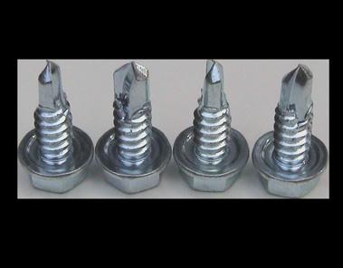
9 Place the control box onto the frame in this position. Secure the rod adapter with pliers. Turn the set screw with a 3/32 Allen wrench to break the Loctite seal at threads. Place the rod adapter through the latch arm. Guide the connecting rod through the rod adapter while sliding the control box into place. See Attaching Connecting Rod to Latch on next page before tightening rod adapter. Ensure the control box is tight against the trigger assembly. Using a 3/8 nut driver and drill, secure the control box to the frame with four #14 self tapping, 3/4 long screws. 9


10 Notice the actuator arm has more than one inch of travel. The actuator arm and connecting rod is shown below fully IN and fully OUT. Do not secure the rod to the latch with the connecting arm all the way out or it will hit the bracket on the latch assembly when triggered. The illustrations below show the proper setting on the right side of the bracket. Using a 3/32 Allen wrench, turn the set screw inside the rod adapter to secure the connecting rod to the latch. Erect feeder and secure each leg with a T-post and 11 gauge galvanized steel wire. Following the steps of our Capture Success Matrix, build an enclosure only after the hogs trust the area as a food source for multiple days in succession. 10


11 Carefully feed the antenna through the rubber grommet without damaging the receiver inside the control box. Feed the antenna wire through the 1/8 diameter antenna tube until it clears the opposite end. Slide the antenna tube into the rubber grommet until it becomes visible inside the control box. This waterproof seal with help keep electrical components clean and dry during field use. The antenna wire in this position rests between two horizontal gate frames and will receive a wireless signal from 250 meters (or 275 yards) when using the long range transmitter. 11


. 3.")
.")
12 Building and installing the enclosure requires at least two people. Assembly and installation without the assistance of another person may result in injury. 1. The opening for the eight foot wide MINE gate should face the natural direction hogs travel to the bait site. Drive a 7 foot long T-post measuring 16 feet from the feeder. This will become the left support post for the 8 foot wide MINE gate (A). 2. Put the gate in position to measure and drive the right support post (B). 3. Measure 16 feet from the rear of the feeder and drive another 7 foot long post to form a 35 foot triangle. This triangle will begin the outside dimension of the trap enclosure (C). (C) (A) (B) Secure Panels to posts in seconds using a drill and M.I.N.E. Post Clips. Standing inside the trap enclosure, install a post clip (11 gauge) around the post and panel (A). Insert a M.I.N.E. Clip Socket onto the post clip (B). Press against the panel while drilling clockwise at full speed (C). (A) (B) (C) 12
.")
.")

 and the horizontal steel rods are on the inside.")

13 Trap shy adult hogs will not step over a threshold. Dig a two-inch trench with a hand pick to conceal the bottom gate frame (A). Use a level to ensure the drop gate remains square for smooth operation. Cover the threshold with dirt and camouflage to blend with surrounding area (B). (A) (B) The panel joint at the gate support post is the weakest link if not secured properly. Ensure the panel s vertical 1/4 steel rods are on the outside of the enclosure (against the post) and the horizontal steel rods are on the inside. Use the post lugs to lock the vertical steel rod between the post and gate support. Pull these twists as tight as possible and reinforce the joint with six anchor points of double stranded 11 gauge galvanized steel wire or a single strand of 9 gauge galvanized steel wire. 13


 shows the proper anchor points needed for")
14 Erect six each panels in a circular shape around the feeder. Each panel is 16 feet long with an eight inch overlap. Ensure all T-post lugs face inward to secure the panels from lifting up. Posts should be driven in the center of each eight inch panel overlap. Each post should secure the panel with at least four M.I.N.E. Post Clips. The diagram (above right) shows the proper anchor points needed for maximum strength. 14


15 This diagram illustrates the proper order to drive posts. Place the camera on #23 and booster antenna pole on #24 outside the enclosure so these devices are not damaged when hogs are captured. Posts should be driven every four feet for maximum strength. Ensure all T-post lugs face inward to secure the panels from lifting up. Posts should be driven in line of a vertical support on single panels. Each post should secure the panel with at least four M.I.N.E. Post Clips. The diagram (above right) shows the proper anchor points needed for maximum strength. 15


16 This diagram illustrates the proper order to erect the rigid panels. Start at one side of gate and position rigid trap panel #1. Position panel #2 next to panel #1. Secure panel #2 to panel #1 using the 5 long connecting stake. Repeat steps to position and secure all twelve panels in a circular shape around feeder. Ensure one-inch steel frames are facing out and the panels are facing inside trap enclosure. Secure rigid trap panel to gate using the 5 long connecting stake. Secure panel #12 to gate using 5 long connecting stake. Do not drive stakes into the ground until all twelve trap panels are positioned. Drive all connecting stakes into the ground with a sledge hammer. 16


17 Thread bracket no more than three complete rotations or it may damage the camera housing. Align the threads of the T-post mounting bracket to the camera mounting port. Tighten securely using the adjusting nut. Mount the M.I.N.E. Camera to post #23 outside the enclosure according to the page 13 diagram. Lower the square collar at a diagonal over the post spine and studs. Lower the collar into position between any two studs. Insert the mounting wedge between the post spine and square collar. Tighten the mounting wedge thumb screw against the post spine to secure the camera mount. Align the camera by loosening the ball head set screw and centering the view on the ground beneath the feeder legs. Tighten the ball head set screw to secure the camera. 17


 and the red light (B) stays on. 2.")
18 Mount the booster antenna pole to post #24 outside the trap enclosure according to the diagram on page 14. The pole is 8 feet tall and telescopes to 16 feet. Secure the booster antenna cable to the antenna pole with zip ties to reduce wind noise. Secure the booster antenna cable to the post with zip ties below the camera antenna port to prevent rainwater from pooling on top of the waterproof boot. The long range transmitter frequencies are timed to the receiver during assembly and quality control. Users may time transmitters to multiple receivers to close more than one gate on a trap enclosure. Timing the M.I.N.E. camera to the control box is covered in the M.I.N.E. camera s Operations Manual. Timing Steps: 1. Press and release the receiver button (A) and the red light (B) stays on. 2. Press and hold transmitter button for 2 second until the light on the transmitter turns on. The receiver light (B) will flash three times and shut off. A B Pressing and holding the receiver button (A) until red light (B) blinks will clear sync memory. 18


19 Ensure the trip arm is in the fully upright position. Raise the gate with both hands. Hold the gate in the fully raised position with the left hand and lower the trip arm s striker into the latch with the right hand. Ensure the latch is fully closed by pressing the latch arm upward. CRUSH HAZARD: Drop gate can cause serious injury or death. ALWAYS ensure that gate area is clear BEFORE testing gate operation. Level the gate by checking the distance at this location on both sides. Slightly adjust if needed to square the gate to frame. Stand clear and press the transmitter button for two seconds. The gate should fall without binding. 19


20 The trap enclosure is built with the gate opening 16 feet from the feeder. This will leave approximately 20 feet of spin cast area without throwing bait outside the enclosure. Below is an example using a JAGER PRO Dinner Bell feeder modification to prevent bait being thrown outside of the trap enclosure. This step keeps bait at least 10 feet away from the entrance, teaching hogs to trust the entire enclosure and ensures they are too far away from the gate to escape when the gate is triggered. It also produces a distinct sound which hogs will learn to associate with daily feeding. DINNER BELL INSTALLED 20
 to the control box receiver.")


21 The long range transmitter will send a wireless signal 250 meters (or 275 yards) to the control box receiver. This device uses a 12 volt alkaline A23 battery. Turn the transmitter over and slide the housing cover down to expose the battery compartment. Replace the A23 battery with the positive terminal facing right and the negative terminal facing left towards the spring. Ensure the negative spring terminal does not touch the side of the battery. Return the housing cover to secure the battery compartment. The red light should emit when the button is pushed for 2 seconds. Test the control box receiver and M.I.N.E. Gate trigger assembly for operation after replacing battery. 21
22 Limited Warranty: JAGER PRO, LLC warrants the Product to be free from malfunctions and defects in both materials and workmanship for one (1) year from the date of purchase ( Warranty Period ). JAGER PRO, LLC will repair or replace, at its option, the Product if it fails to function properly during the Warranty Period, subject to the conditions and/or limitations stated herein. Such repair or replacement is your sole remedy under this Limited Warranty. Limitations: Limited Warranty service will not be provided unless the Product, returned in the manner set forth below, is accompanied by a copy of your original dated sales invoice. JAGER PRO, LLC reserves the right to require you to provide your original dated sales invoice. Products purchased from non-authorized dealers may not qualify for warranty coverage. This Limited Warranty does not cover the following: a. any defect in or damage to the Product that occurs due to mishandling of the Product; b. any defect in or damage to the Product that occurs due to repair, modification, or other similar activity after your purchase of the Product; c. any defect in or damage to the Product that occurs due to the transport, dropping, shock, or other similar activity after your purchase of the Product; d. any defect in or damage to the Product that occurs due to careless or improper storage, or improper use or maintenance of the Product; e. any defect in or damage to the Product that occurs due to foreign objects such as dirt or grime, sand, water or liquids entering the inside of the Product; and f. any defect to the Product related to your failure to follow proper operating instructions provided by JAGER PRO, LLC, claims made after the Warranty Period, or your failure to follow the instructions set forth below with respect to return of the Product to JAGER PRO, LLC. All other express and implied warranties for the product, including the implied warranties of merchantability and fitness for a particular purpose are hereby disclaimed. JAGER PRO, LLC expressly disclaims all warranties not stated in this warranty. Any implied warranties that may be imposed by law are limited in duration to the terms of this express limited warranty. In no event will JAGER PRO, LLC be liable to you, or any third party, for any damages in excess of the purchase price of the product. In addition, JAGER PRO,LLC shall in no event be liable to you, or any third party, for any direct or indirect damages or other special, incidental, exemplary or consequential damages arising out of the use or inability to use the product. Notwithstanding any terms of this Limited Warranty to the contrary, no warranty coverage shall be provided for a Product purchased from, through, or with the assistance or involvement of any Internet auction web site. JAGER PRO, LLC reserves the right to modify its warranties prospectively at any time, in its sole discretion. 22


23 JAGER PRO offers a complete line of Hog Control Products, Services and Education View our instructional video series online at A Smith Road Fortson, GA Phone: info@jagerpro.com Website: 23
ADJUSTABLE COMFORT ASSEMBLY INSTRUCTIONS
 ASSEMBLY INSTRUCTIONS ASSEMBLY INSTRUCTIONS For customer service call 1-877-707-7533 or email azcustomerservice@classicbrands.org STEP 1: Carefully open the carton and remove all boxes then lay out the
Installation Manual TWM Performance Short Shifter Cobalt SS/SC, SS/TC, HHR SS, Ion Redline and Saab 9-3
 Page 1 Installation Manual TWM Performance Short Shifter Cobalt SS/SC, SS/TC, HHR SS, Ion Redline and Saab 9-3 Please Note: It is preferable to park on a flat surface, as you will have to engage and disengage
INSTALLATION INSTRUCTIONS
 INSTALLATION INSTRUCTIONS Universal Short Throw Projector Wall Mount Model: NORTH AMERICA 3130 East Miraloma Avenue Anaheim, CA 92806 USA USA and Canada Phone: 1-800-368-9700 Fax: 1-800-832-4888 Other
User Manual. Posture+ Adjustable Base. For customer service call:
 User Manual Posture+ Adjustable Base For customer service call: 1-877-707-7533 1 IMPORTANT INFORMATION PLEASE READ THESE INSTRUCTIONS THOROUGHLY BEFORE USING THIS PRODUCT. PROPER OPERATION OF YOUR ADJUSTABLE
Installation Instructions
 Installation Instructions AMP RESEARCH Power Step by Bestop Automatic Retracting Running Board Vehicle Application Nissan Titan King Cab 2004 and newer (5 ft.) Part Number: 75106-01 Nissan Titan Crew Cab
TBM Series 3-Way Ball Valve
 www.simtechusa.com TBM Series 3-Way Ball Valve Operating, Installation, & Maintenance Manual Corrosion Resistant Fluid and Air Handling Systems. Dated 06-26-13 TBM Series Ball Valves SIMTECHRECOMMENDSREADINGTHEFOLLOWINGINFORMATIONPRIORTOINSTALLINGANDUSING
EASYBIRD OSCILLATING BASE 12VDC Part No
 EASYBIRD OSCILLATING BASE 12VDC Part No. 40913 Instruction Manual WARNING! TO AVOID SERIOUS INJURY THOROUGHLY READ INSTRUCTIONS BEFORE USING OSCILLATING BASE. i Table of Contents Section Page I. Introduction...
Model 2008 I Battery Operated Irrigation Timer with 3/4 in. Anti-Siphon Valve
 i n s t r u c t i o n m a n u a l Model 2008 I Battery Operated Irrigation Timer with 3/4 in. Anti-Siphon Valve Features Weekly or cyclical programming 4 start times per day in weekly program Irrigation
INSTALLATION INSTRUCTIONS
 INSTALLATION INSTRUCTIONS Thank you for purchasing ROLTECTM Electric Hopper Conversion. Agri-Cover, Inc. proudly manufactured this hardware using superior quality materials and workmanship. With proper
Electric Pilot System Assembly, Operation, & Maintenance
 Electric Pilot System Assembly, Operation, & Maintenance Congratulations on your purchase, and thank you for selecting the Electric Pilot System from Blichmann Engineering Pro Series. We are confident
Electric Pilot System
 Electric Pilot System Assembly, Operation & Maintenance Congratulations on your purchase, and thank you for selecting the Pro Pilot System from Blichmann Engineering. We are confident that it will provide
Installation Manual TWM Performance Short throw shifter 2001 and up Hyundai Accent
 Installation Manual TWM Performance Short throw shifter 2001 and up Hyundai Accent 1. Place the vehicle on a flat surface with blocks in front and behind the wheels preventing unwanted movement. The car
Please visit for the latest version of these installation instructions.
 Please visit www.blueox.com for the latest version of these installation instructions. 2014-2017 Ram 2500 (All beds) Please read these in their entirety prior to installing or operating this equipment.
BX Jeep Liberty Renegade 2012 Jeep Liberty Sport Installation Instructions
 Attachment Tab Height: 17.5 Attachment Tab Width: 24 Serial Number Please read BOTH these and the General Instructions prior to installing or operating this equipment. 1. Blue Ox towing products and accessories
Motorized Stainless 2-Way Valves
 Installation and Operation Manual Motorized Stainless 2-Way Valves Safety Valve ETV Applications WARNING This Heat-Timer valve is strictly an operating valve; it should never be used as a primary limit
i n s t r u c t i o n m a n u a l
 i n s t r u c t i o n m a n u a l 8006 Six-Station AC Timer Residential/Light Commercial Independent Program Irrigation Controllers Installation, Programming and Operating Instructions Features Operates
Installation Instructions. Fog Lights. The lamps get very hot when they have been in use. Do not touch them as they may cause burns.
 2100X Installation Instructions Thank you very much for purchasing PIAA product. Please read this entire manual before installation and use of this product. Fog Lights For Installers Please give this Installation
Installation Instructions
 Installation Instructions Automatic Retracting Running Board Vehicle Application Ford F150 Supercrew 2001-2003 (2004 Heritage) Part Number: 75111-01 www.bestop.com - We re here to help! Visit our web site
Installation Instructions PowerBoard Automatic Retracting Running Board
 Installation Instructions PowerBoard Automatic Retracting Running Board Vehicle Application Dodge Ram Quad Cab Pickup 2002-2008 : 75101-15 Dodge Ram Quad Cab Pickup, 2500 / 3500 / HD 2003-2009 : 75101-15
CS Fiber Optic Splice Case. Instruction
 3 2179-CS Fiber Optic Splice Case Instruction 2179-CS Fiber Optic Splice Case Description 1.0 General 1.1 The 3M 2179-CS Fiber Optic Splice Cases are closures that can be used in buried, underground, aerial,
LifeGuardLift. LifeGuard Power Lift Model #100287A OWNERS MANUAL. Rev: 2/14/11
 LifeGuardLift OWNERS MANUAL LifeGuard Power Lift Model #100287A Rev: 2/14/11 Table of Contents 1. ASSEMBLY INSTRUCTIONS A. Lift Assembly B. Setup C. Disassembly 2. CONTROL SYSTEM A. Batteries B. Battery
Installation Manual TWM Performance Full replacement short shifter assembly Civic all trims and models
 Installation Manual TWM Performance Full replacement short shifter assembly 2006+ Civic all trims and models Begin the installation by parking on a flat surface, as you will have to engage and disengage
INSTALLATION INSTRUCTIONS
 THANK YOU FOR CHOOSING KURYAKYN! Protect yourself and others from possible injury and property damage or loss. Pay close attention to all instructions, warnings, cautions, and notices regarding the installation,
Installation Instructions PowerBoard Automatic Retracting Running Board
 Installation Instructions PowerBoard Automatic Retracting Running Board Vehicle Application Dodge Ram Quad Cab Pickup 2002-2008 Part Number: 75101-15 Dodge Ram Quad Cab Pickup, 2500 / 3500 / HD 2003-2009
Mercedes MBE 906/ L & 7.2L Engine Module. Part # Installation Instructions
 1999-2006 Mercedes MBE 906/926 6.4L & 7.2L Engine Module Part # 15000 Installation Instructions 15000_revC 1999-2006 Mercedes 6.4L & 7.2L Engine Module +12 volts red wire. Ground black wire Injector Terminals
Installation Instructions PowerBoard Automatic Retracting Running Board
 Installation Instructions PowerBoard Automatic Retracting Running Board Vehicle Application Toyota Tundra Double Cab 2007 Current Part Number: 75136-15 Toyota Tundra CrewMax 2007 Current Part Number: 75137-15
Installation Instructions PowerBoard Automatic Retracting Running Board
 Installation Instructions PowerBoard Automatic Retracting Running Board Vehicle Application Dodge Ram 1500 Crew Cab 2009 - Current : 75138-15 Dodge Ram 2500/3500 & HD Crew Cab 2010 - Current : 75138-15
Model P-40 & Model P-25 POWER PUSHER
 Power Pusher Description INSTRUCTION MANUAL The Power Pusher provides ram capability by using the spreading power of the POWER HAWK P-16 Rescue Tool. (The Power Pusher may also be used with other spreader
VW/AUDI MK7 VEHICLES
 Installation Manual P/N 1-301-1708-01 (STAGE 2+ FUEL KIT) P/N 1-301-1708-02 (STAGE 3+ FUEL KIT) VW/AUDI MK7 VEHICLES Warning: This installation is not recommended for a novice or the new guy in the shop.
READ THIS MANUAL CAREFULLY BEFORE USING THE PUMP
 OWNER S MANUAL Pond Pump READ THIS MANUAL CAREFULLY BEFORE USING THE PUMP Important Notice: This manual contains important information about the installation, operation and safe use of this product. This
Remote Vehicle Control System. Keyless Entry & Remote Start System
 1 Remote Vehicle Control System PC 7400 TM Owner's Manual Keyless Entry & Remote Start System IMPORTANT NOTE: The operation of the Power Code as described in this manual is applicable to most vehicles.
VW Shift Paddle Kit Installation Instructions
 VW Shift Paddle Kit Installation Instructions Parts Included: (1) Left and right shift paddle (1) Small pick tool (1) Hex key (1) T20 Torx key (1) Loctite capsule Tools Needed: Medium flat-heat screwdriver
 CUSTOMER SERVICE: 800-973-8374 Frame Assembly Instructions Headboard Installation E 1. Use the remote control to raise the head of the adjustable foundation in order to gain access to the foundation
Mega-Rail System Installation
 Installation Manual Mega-Rail System P/N 030767-MRS 2003-2007 DODGE CUMMINS Mega-Rail System Installation Installation Instructions GDP 03-07 Mega-Rail System P/N 030767-MRS PLEASE READ ALL INSTRUCTIONS
Please visit for the latest version of these installation instructions.
 Please visit www.blueox.com for the latest version of these installation instructions. BX1726 (All Models) (No Active Shutters or E-Assist) Attachment Tab Height: 12 Serial Number Attachment Tab Width:
Remote Vehicle Control System. Keyless Entry and Convenience System
 1 Remote Vehicle Control System PC 6100 TM Owner's Manual Keyless Entry and Convenience System IMPORTANT NOTE: The operation of the Power Code as described in this manual is applicable to most vehicles.
OWNER S MANUAL Z SERIES TRACKS. Rev. 355_05
 OWNER S MANUAL Z SERIES TRACKS Rev. 355_05 LOEGERING 800-373-5441 15514 37 th Street SE 701-347-5441 Casselton, ND 58012 USA Fax: 701-347-4323 E-Mail: lmi@loegering.com Internet: www.loegering.com Loegering
Jeep Wrangler (TJ)
") INSTALLATION GUIDE APPLICATION MODEL YR PART # Bestop PART # Jeep Wrangler (TJ) 2003 2006 10-03315-10 751-01 INSTALLATION TIME 3:00 hrs SKILL LEVEL 1 2 3 4 4= Experienced TOOLS REQUIRED Safety goggles
INSTALLATION GUIDE APPLICATION MODEL YR PART # Bestop PART # Jeep Wrangler (TJ) 2003 2006 10-03315-10 751-01 INSTALLATION TIME 3:00 hrs SKILL LEVEL 1 2 3 4 4= Experienced TOOLS REQUIRED Safety goggles
Please visit for the latest version of these installation instructions.
 Please visit www.blueox.com for the latest version of these installation instructions. BX1730 Attachment Tab Height: 16 Serial Number Attachment Tab Width: 23 Please read BOTH these and the General Information
CLEAN ROOM DEVICES, LLC "WHERE TUBING AND FITTINGS COME TOGETHER"
 CLEAN ROOM DEVICES, LLC "WHERE TUBING AND FITTINGS COME TOGETHER" CRD600 Automatic Fitting Inserter OPERATIONS MANUAL VERSION 2.1 LAST EDITED 7.25.14 DOCUMENT NUMBER 001 cleanroomdevices.com 1 Table of
Model AS-RC3260 TV Cart. Rolling Cart for Audio Mount System & Flat Panel TVs
 Model AS-RC3260 TV Cart Rolling Cart for Audio Mount System & Flat Panel TVs GETTING STARTED Introduction Congratulations on the purchase of your new Helios AS-RC3260 Rolling Cart. For maximum benefit,
Installation Instructions
 Installation Instructions Thank you very much for purchasing PIAA product. Please read this entire manual before installation and use of this product. For Installers Please give this Installation Manual
INSTALLATION GUIDE. AMP RESEARCH TECH SUPPORT (Press 2) Monday - Friday, 6:00 AM - 5:00 PM PST
 Monday - Friday, 6:00 AM - 5:00 PM PST") INSTALLATION GUIDE APPLICATION MODEL YR PART # Chevy Tahoe / GMC Yukon / Cadillac Escalade * 2007 - up 75125-01A Chevy Suburban / GMC Yukon XL / Escalade ESV 2007 - up 75125-01A Chevy Avalanche / Escalade
INSTALLATION GUIDE APPLICATION MODEL YR PART # Chevy Tahoe / GMC Yukon / Cadillac Escalade * 2007 - up 75125-01A Chevy Suburban / GMC Yukon XL / Escalade ESV 2007 - up 75125-01A Chevy Avalanche / Escalade
Installation Instructions PowerBoard Automatic Retracting Running Board
 Installation Instructions PowerBoard Automatic Retracting Running Board Vehicle Application Ford F150 Super Crew Cab 2009 Current : 75141-15 www.bestop.com - We re here to help! Visit our web site and
Owners Manual. LifeGuard Power Lift Model # Rev. 2/1/13
 Owners Manual LifeGuard Power Lift Model #100287 Rev. 2/1/13 Table of Contents 1. ASSEMBLY INSTRUCTIONS 3-5 A. Lift Assembly 3 B. Setup 3 1. Clinch Pin Location Drawings 4 2. Down Tube and Seat Assembly
Please visit for the latest version of these installation instructions.
 Please visit www.blueox.com for the latest version of these installation instructions. BX2414 2019 Ram 1500 (Includes Rebel) (No Classic) Attachment Tab Height: 17 Serial Number Attachment Tab Width: 38.5
CLASSIC II Portable Braking System
 39495 CLASSIC II Portable Braking System Inventor and Leader in Portable Technology! INSTRUCTIONS NEED HELP? CALL - 1-800-470-2287 (MONDAY - FRIDAY 8AM - 5PM CST) WARNING Read all instructions before installing
Breeder Control Installation Manual
 Breeder Control Installation Manual Patented U.S. Patent No. 7,980,129, Patent No. 8,581,122, Patent No. 8,853,566 07/10/2018 Table of Contents Installation Overview... 3 Components... 3 BinTrac Breeder
ActuLink ABS Module - ABS-MOD-400
 Installation Instructions ActuLink ABS Module - ABS-MOD-400 For more information on the installation and operation of Tuson s towable ABS system, consult the installation and operations manuals for the
CLEAN ROOM DEVICES, LLC "WHERE TUBING AND FITTINGS COME TOGETHER"
 CLEAN ROOM DEVICES, LLC "WHERE TUBING AND FITTINGS COME TOGETHER" CRD600AF Automatic Fitting Inserter With Auto Feed OPERATIONS MANUAL (Shown with optional alcohol dispenser) 1 VERSION 1.1 LAST EDITED
CRD610 Automatic Fitting Inserter
 CRD610 Automatic Fitting Inserter OPERATIONS MANUAL VERSION 1.2 LAST EDITED 12.12.2018 cleanroomdevices.com 1 Table of Contents Title Page. 1 Table of Contents...2 1.0 General Product & Safety Information....3
CYCLE COMPUTER OWNER'S MANUAL ENGLISH FRANÇAIS ESPANOL DEUTSCH ITALIANO
 CYCLE COMPUTER OWNER'S MANUAL ENGLISH FRANÇAIS ESPANOL DEUTSCH ITALIANO INTRODUCTION Congratulations on your purchase of the new Vetta C-06 cycle computer. The C-06 is designed to be the simplest, smallest
Please visit for the latest version of these installation instructions.
 Please visit www.blueox.com for the latest version of these installation instructions. Attachment Tab Height: 19-1/2 Serial Number Attachment Tab Width: 19 Please read BOTH these and the General Information
TRAILER AUXILIARY POWER SYSTEM (TAPS) INSTALLATION GUIDE V1.10
 INSTALLATION GUIDE V1.10") TRAILER AUXILIARY POWER SYSTEM (TAPS) INSTALLATION GUIDE V1.10 TAPS INSTALLATION GUIDE V1.10 1 TRAILER AUXILIARY POWER SYSTEM CONTENTS General Information and System Logic... 2 Diagrams... 3 System Diagram
TRAILER AUXILIARY POWER SYSTEM (TAPS) INSTALLATION GUIDE V1.10 TAPS INSTALLATION GUIDE V1.10 1 TRAILER AUXILIARY POWER SYSTEM CONTENTS General Information and System Logic... 2 Diagrams... 3 System Diagram
Addendum to GPD-30 Owner s Manual
 Addendum to GPD-30 Owner s Manual Rhino GPD-30 Ranch Pro Effective February 5, 2014 Information herein list specific updates to the contents and supercedes Owner s Manual form no. GPD30-800-04/2013. Please
LB LB LLY LLY 1000
 6 November 2006 GMC/Chevy Allison Performance Transmission 1 BD PERFORMANCE TRANSMISSION Allison Installation Instructions 2WD Transmissions 4WD Transmissions 1064702 2000-2003 LB7 1000 1064704 2000-2003
MODEL G300 BRAKE BLEEDER
 MODEL G300 BRAKE BLEEDER Installation, Operation & Repair Parts Information Branick Industries, Inc. 4245 Main Avenue P.O. Box 1937 Fargo, North Dakota 58103 REV120716 P/N: 81-0035H THIS PAGE INTENTIONALLY
GM 6.6L Duramax. Up to 90HP Gain. AgDieselSolutions.com
 21700 Module Installation Guide 2017 GM 6.6L Duramax *L5P* Up to 90HP Gain 1-3 MPG Fuel Savings AgDieselSolutions.com Adjustable Switch Female Fuel Pressure Sensor Connector Male Fuel Pressure Sensor Connector
JD2800 Module Installation Guide
 Up to 30% More Horsepower 10-20% Fuel Savings John Deere 9.0L Tier III Denso Common Rail Engines JD2800 Module Installation Guide AgDieselSolutions.com Ground Terminal Power (+12V constant) Terminal Injector
Lubricator Gun: 10,000 psi (700 bar) Maximum Delivery Pressure when disconnected from Dispenser
 Maximum Delivery Pressure when disconnected from Dispenser") INSTRUCTIONS-PARTS LIST 30 455 INSTRUCTIONS This manual contains important warnings and information. READ AND KEEP FOR REFERENCE. Rev. C Supercedes B Hand-Operated Portable Grease Dispenser Buckshot Luber
INSTRUCTIONS-PARTS LIST 30 455 INSTRUCTIONS This manual contains important warnings and information. READ AND KEEP FOR REFERENCE. Rev. C Supercedes B Hand-Operated Portable Grease Dispenser Buckshot Luber
Model MC-30D Impact Press. Operation & Maintenance Instructions
 Model MC-30D Impact Press Operation & Maintenance Instructions Revised 12/05/2007 1 WARNINGS 1. Safety glasses must always be worn by the machine operator, as well as any co-workers, or any other persons
OWNER S MANUAL. 6. If you aren t competent to instal the pump, get help from a qualified source.
 OWNER S MANUAL RK2 Systems Pro Pump Energy-Efficient, Self Priming Centrifugal Pumps Important Safety Instructions Please read all instructions completely before you install or operate your new pump. Save
MaxLite LED Linear HighBay Fixtures
 Operating Instructions MaxLite LED Linear HighBay Fixtures General Safety Information To reduce the risk of death, personal injury or property damage from fire, electric shock, falling parts, cuts/abrasions,
Model BP6150. Triplex Ceramic Plunger Pump Operating Instructions/ Manual
 Model BP6150 Triplex Ceramic Plunger Pump Operating Instructions/ Manual Contents: Installation Instructions: page 2 Pump Specs: page 3 Exploded View: page 4 Parts List / Kits Torque Specifications: page
Installation Instructions PowerBoard Automatic Retracting Running Board
 Installation Instructions PowerBoard Automatic Retracting Running Board Vehicle Application Dodge Ram Quad Cab Pickup 2002-2008 : 75101-15 Dodge Ram Mega Cab Pickup 2006-2009 : 75118-15 www.bestop.com
SPECIFICATIONS CONTENTS:
 Model 3052A 1,100 Lbs Air Assist 2 Stage Transmission Jack INSTRUCTION MANUAL CONTENTS: Page 1 Specifications Page 2 Warning Information Page 3 Assembly Page 4 Operating Instructions Page 4 Preventative
I N S T A L L A T I O N G U I D E. Ford Transit - Single Sided A (All slider and barn door models)
") I N S T A L L A T I O N G U I D E APPLICATION MODEL YR PART # Ford Transit - Single Sided 2014-2017 76159-01A (All slider and barn door models) INSTALLATION TIME 3-5 Hours Professional installation recommended
I N S T A L L A T I O N G U I D E APPLICATION MODEL YR PART # Ford Transit - Single Sided 2014-2017 76159-01A (All slider and barn door models) INSTALLATION TIME 3-5 Hours Professional installation recommended
Stop! Read This Important Information.
 Stop! Read This Important Information. Stop, Do Not Proceed, Read This This door replacement kit is designed for the replacement of doors on a Supertop ONLY! This door will not work on any other style
PIAA Multi-Fit 005/1100X Light Bracket Kits
 ENGLISH PIAA Multi-Fit 005/1100X Light Bracket Kits Thank you for your purchase. Please read all the instructions before beginning.! WARNING Lighting laws vary state to state, check your local laws before
Universal Bench-top Conveyor OPERATOR S GUIDE
 OPERATOR S GUIDE DISCLAIMER LIABILITY LIMITATION: The Buyer of this product accepts full responsibility and understanding for the terms and specifications set forth herein. Con-Trol-Cure makes no claim,
LUBRICATOR GUN INSTRUCTIONS-PARTS LIST. 10,000 psi (700 bar) Maximum Delivery Pressure. Detachable-type
 Maximum Delivery Pressure. Detachable-type") INSTRUCTIONS-PARTS LIST 306 460 INSTRUCTIONS This manual contains important warnings and information. READ AND KEEP FOR REFERENCE. Rev. E Supercedes D Detachable-type LUBRICATOR GUN 10,000 psi (700 bar)
INSTRUCTIONS-PARTS LIST 306 460 INSTRUCTIONS This manual contains important warnings and information. READ AND KEEP FOR REFERENCE. Rev. E Supercedes D Detachable-type LUBRICATOR GUN 10,000 psi (700 bar)
EASYBIRD AUTO-FEED 6 - PACKER Part No (40912 with Oscillating Base)
") EASYBIRD AUTO-FEED 6 - PACKER Part No. 40911 (40912 with Oscillating Base) Instruction Manual WARNING! THIS MACHINE CAN CAUSE SERIOUS INJURY OR DEATH. THOROUGHLY READ INSTRUCTIONS BEFORE INSTALLING OR
EASYBIRD AUTO-FEED 6 - PACKER Part No. 40911 (40912 with Oscillating Base) Instruction Manual WARNING! THIS MACHINE CAN CAUSE SERIOUS INJURY OR DEATH. THOROUGHLY READ INSTRUCTIONS BEFORE INSTALLING OR
APCO CRF-100A RUBBER FLAPPER SWING CHECK VALVES
 APCO CRF-100A RUBBER FLAPPER SWING CHECK VALVES Instruction D12043 June 2016 DeZURIK Instructions These instructions provide installation, operation and maintenance information for APCO CRF-100A Rubber
Please visit for the latest version of these installation instructions.
 Please visit www.blueox.com for the latest version of these installation instructions. BX1728 2017-18 GMC Acadia (Includes Denali & All-Terrain) (No Limited) Attachment Tab Height: 16 Serial Number Attachment
WARNING. Laser light is extremely bright and can potentially cause permanent eye damage or interfere with critical operations if improperly used.
 TG7630G / TG7630R TRUGLO, Inc. 525 International Parkway RICHARDSON, TEXAS 75081 MADE IN CHINA Green Laser: POWER OUTPUT
PACIFICA Shower Cabin Installation Instructions
 PACIFICA Shower Cabin Installation Instructions IMPORTANT Please read carefully the following instructions before installing your shower cabin. If you have any questions on this shower cabin installation
Please visit for the latest version of these installation instructions.
 Please visit www.blueox.com for the latest version of these installation instructions. Attachment Tab Height: 16.5 Serial Number Attachment Tab Width: 30.5 Please read BOTH these and the General Information
E9X/E8X/E6X CHASIS VEHICLES (With N54 Motors)
") Installation Manual P/N 1-301-1706-01 (N54 Coil-Pack Conversion Kit) E9X/E8X/E6X CHASIS VEHICLES (With N54 Motors) Warning: This installation is not recommended for a novice or the new guy in the shop.
Installation Manual P/N 1-301-1706-01 (N54 Coil-Pack Conversion Kit) E9X/E8X/E6X CHASIS VEHICLES (With N54 Motors) Warning: This installation is not recommended for a novice or the new guy in the shop.
Installation Instructions PowerBoard Automatic Retracting Running Board
 Installation Instructions PowerBoard Automatic Retracting Running Board Vehicle Application Chevy Silverado/GMC Sierra Extended Cab 2007 and newer (excluding 2011 Diesels) Part Number: 75123-15 Chevy Silverado/GMC
1500- LB. HIGH POSITION HOIST STAND OWNER S MANUAL
 1500- LB. HIGH POSITION HOIST STAND OWNER S MANUAL WARNING: Read carefully and understand all ASSEMBLY AND OPERATION INSTRUCTIONS before operating. Failure to follow the safety rules and other basic safety
OWNER S MANUAL. LOEGERING th Street SE Casselton, ND USA Fax:
 OWNER S MANUAL TRAIL BLAZERS and D SERIES TRACKS LOEGERING 800-373-5441 15514 37 th Street SE 701-347-5441 Casselton, ND 58012 USA Fax: 701-347-4323 E-Mail: lmi@loegering.com Internet: www.loegering.com
TECHNICAL SERVICE MANUAL
 Electronic copies of the most current TSM issue can be found on the Viking Pump website at www.vikingcom TECHNICAL SERVICE MANUAL abrasive liquid pumps SERIES 4625 SIZES f - fh SECTION TSM 410.1 PAGE 1
PRODUCT OBSOLETED 4Q16
 Electronic copies of the most current TSM issue can be found on the Viking Pump website at www.vikingcom TECHNICAL SERVICE MANUAL abrasive liquid pumps SERIES 4625 SIZES f - fh SECTION TSM 410.1 PAGE 1
Please visit for the latest version of these installation instructions.
 Please visit www.blueox.com for the latest version of these installation instructions. DH2400 (Long & Standard Box) Please read these in their entirety prior to installing or operating this equipment.
Installation Instructions PowerBoard Automatic Retracting Running Board
 Installation Instructions PowerBoard Automatic Retracting Running Board Vehicle Application Ford Super Duty F-250/350/450 Crew Cab 2008 and newer Part Number: 75134-15 www.bestop.com - We re here to help!
BEFORE YOU BEGIN LIST OF COMPONENTS. Isopropyl SWITCH SCOTCH-BRITE PAD ALCOHOL PREP PAD SWITCH HARNESS REVOLVER PCM COVER STICKER
 User Manual TABLE OF CONTENTS BEFORE YOU BEGIN...3 LIST OF COMPONENTS... 3 REVOLVER INSTALLATION 95-97 Trucks...4 REVOLVER INSTALLATION 98-03 Trucks...7 SWITCH INSTALLATION...12 SAFETY WARNING & CAUTION...14
IMPORTANT! 09 to Current Straight Up Electric Billet Center Stand. Dealer and/or Customer must complete the following items: Center Stand Checklist
 IMPORTANT! 09 to Current Straight Up Electric Billet Center Stand Dealer and/or Customer must complete the following items: Center Stand Checklist 1. Complete the Measurement Guide 2. Read the Operation
I N S T A L L A T I O N G U I D E. Chevrolet Silverado / GMC Sierra - Ext Cab * A (Diesel Only)
") I N S T A L L A T I O N G U I D E APPLICATION AMP Part # Chevrolet Silverado / GMC Sierra - Crew Cab 2011-201 751-01A (Diesel Only) Chevrolet Silverado / GMC Sierra - Ext Cab 2011-201* 751-01A (Diesel
I N S T A L L A T I O N G U I D E APPLICATION AMP Part # Chevrolet Silverado / GMC Sierra - Crew Cab 2011-201 751-01A (Diesel Only) Chevrolet Silverado / GMC Sierra - Ext Cab 2011-201* 751-01A (Diesel
DUAL WIDEBAND AIR/FUEL RATIO GAUGE Product Numbers: GS-W702W_Dual, GS-C702W_Dual, GS-T702W_Dual
 Installation Instructions Tech Support: 856.768.8300 TechSupport@GlowShiftGauges.com DUAL WIDEBAND AIR/FUEL RATIO GAUGE Product Numbers: GS-W702W_Dual, GS-C702W_Dual, GS-T702W_Dual (1) Gauge (2) Controllers
Installation Instructions
 Installation Instructions HighRock 4x4 TM Rear Bumper and Tire Carrier Vehicle Application: 2007 - Current Jeep Wrangler and Wrangler Unlimited HighRock 4x4 TM Rear Bumper and Tire Carrier Part Number:
Installation Manual TWM Performance Short Shifter Subaru STi 2008+
 - 1 - Installation Manual TWM Performance Short Shifter Subaru STi 2008+ Please Note: It is preferable to park on a flat surface, as you will have to engage and disengage the hand brake and shift from
Table of Contents. How the Surestart SE 433 Operates Starting the Vehicle with the Remote Starter... 3
 Table of Contents How the Surestart SE 433 Operates... 3 Starting the Vehicle with the Remote Starter... 3 Stopping the Vehicle While It Is Running Via the Remote Starter... 4 Operating Your Vehicle While
Please visit for the latest version of these installation instructions.
 Please visit www.blueox.com for the latest version of these installation instructions. BX1718 2015-18 Chevy Suburban/Tahoe 2015-18 GMC Yukon/Yukon XL (Includes Denali) Please read BOTH these and the General
54" Galvanized Hyflo Fan Installation & Operator s Instruction Manual
 54" Galvanized Hyflo Fan Installation & Operator s Instruction Manual Thank You The employees of CTB Inc. would like to thank you for your recent Chore-Time purchase. If a problem should arise, your Chore-Time
JOHNSON/EVINRUDE 9.9 & 15HP SUZUKI For motors see below
 JOHNSON/EVINRUDE 9.9 & 15HP 2003-2010 SUZUKI 2003-2011 For motors 2005-2011 see below TrollMaster is a precision throttle control designed to achieve the maximum in trolling speed accuracy. The memory
Installation Instructions PowerBoard Automatic Retracting Running Board
 Installation Instructions PowerBoard Automatic Retracting Running Board Vehicle Application Chevy Silverado/GMC Sierra Extended Cab Diesel 2011 and newer Part Number: 75147-15 Chevy Silverado/GMC Sierra
Important Information
 Boat Lift Boss Installation Instructions For Metal Craft Lifts (Kit 3005.7204) Important Information Before installation, read and understand all instructions and warnings. All 120 Volt units MUST have
EZ-R7 T-Plug. Universal 7-Pin Heavy Duty Plug For Vehicles equipped with 7-Way Trailer Connectors. Installation Instructions and Product Warranty
 EZ-R7 T-Plug Universal 7-Pin Heavy Duty Plug For Vehicles equipped with 7-Way Trailer Connectors Installation Instructions and Product Warranty Professional Installation Required Thank you for purchasing
Please visit for the latest version of these installation instructions.
 Please visit www.blueox.com for the latest version of these installation instructions. Attachment Tab Height: 16 Serial Number Attachment Tab Width: 35 Please read BOTH these and the General Information