TGC Series Guillotine Cutter
|
|
|
- Frank Reynolds
- 5 years ago
- Views:
Transcription
: 800.458.1960 l Parts and Service: 814.437.")
1 Black C=0 M=0 Y=0 K=100 Grey C=10 M=5 Y=0 K=30 Green C=50 M=0 Y=100 K=0 Second surface printed 10 mil Bayfol UV-1 3M 468 adhesive backing on white carrier USER GUIDE UGE TGC Series Guillotine Cutter Conair TS Saw Corporate Office: l Instant Access 24/7 (Parts and Service): l Parts and Service:
2 Please record your equipment s model and serial number(s) and the date you received it in the spaces provided. It s a good idea to record the model and serial number(s) of your equipment and the date you received it in the User Guide. Our service department uses this information, along with the manual number, to provide help for the specific equipment you installed. Please keep this User Guide and all manuals, engineering prints and parts lists together for documentation of your equipment. Date: Manual Number: UGE Serial Number(s): Model Number(s): DISCLAIMER: Conair shall not be liable for errors contained in this User Guide or for incidental, consequential damages in connection with the furnishing, performance or use of this information. Conair makes no warranty of any kind with regard to this information, including, but not limited to the implied warranties of merchantability and fitness for a particular purpose. Copyright 2015 l Conair l All rights reserved
3 Table of Contents 1-1 Introduction 2-1 Description 3-1 Installation Purpose of the User Guide How the Guide Is Organized Your Responsibilities as a User ATTENTION: Read This So No One Gets Hurt How to Use the Lockout Device What is the TGC Guillotine Cutter? Typical Applications How the TGC Series Guillotine Works TGC Guillotine Features Specifications Optional Equipment Unpacking the Boxes Preparing for Installation Positioning the TGC Cutter Connecting the Main Power Source Installing the Encoder Installing and Replacing the Blade Preparing for Testing Testing the Installation Operation TGC Guillotine Splash Screen How to Navigate the Control Screens TGC Guillotine Control Instructions Main Screen TGC Guillotine Control Instructions Menu Screen Control Function Flow Charts Control Function Descriptions The Cutter Control Machine Frame and Support System Blade Height Adjustment Upper Clamp Adjustment Power Supply Control Panels Table of Contents l i
4 4-1 Operation (continued) Pneumatic Cylinder Operation Electrical Operation Machine Lubrication System Inspection Blade Replacement Chip Collection Shrouds & Blower Connection Maintenance (continued) Maintenance Features Warnings and Cautions Maintenance Overview Preventative Maintenance Schedule Checking Electrical Connections Troubleshooting Before Beginning A Few Words of Caution Identifying the Cause of a Problem Electrical Problems Product Quality Problems TGC Guillotine Fault Messages Checking the Servo Amplifiers Checking the Encoder A Appendix Customer Service Information A-1 Warranty Information A-2 ii l Table of Contents
5 SECTION 1 Introduction 1 Introduction Purpose of the User Guide How the Guide Is Organized Your Responsibilities as a User ATTENTION: Read This So No One Gets Hurt How to Use the Lockout Device Introduction l 1-1
6 Purpose of the User Guide This User Guide describes the Conair TGC Series Guillotine Cutter and explains step-bystep how to install and operate this equipment. Before installing this product, please take a few moments to read the User Guide and review the diagrams and safety information in the instruction packet. You also should review manuals covering associated equipment in your system. This review won t take long, and it could save you valuable installation and operating time later. How the Guide is Organized Symbols have been used to help organize the User Guide and call your attention to important information regarding safe installation and operation. 1 Symbols within triangles warn of conditions that could be hazardous to users or could damage equipment. Read and take precautions before proceeding. Numbers indicate tasks or steps to be performed by the user. A diamond indicates the equipment s response to an action performed by the user. An open box marks items in a checklist. A circle marks items in a list. Indicates a tip. A tip is used to provide you with a suggestion that will help you with the maintenance and the operation of this equipment. Indicates a note. A note is used to provide additional information about the steps you are following throughout the manual. Your Responsibility as a User You must be familiar with all safety procedures concerning installation, operation, and maintenance of this equipment. Responsible safety procedures include: Thorough review of this User Guide, paying particular attention to hazard warnings, appendices, and related diagrams. Thorough review of the equipment itself, with careful attention to voltage sources, intended use and warning labels. Thorough review of instruction manuals for associated equipment. Step-by-step adherence to instructions outlined in this User Guide. 1-2 l Introduction
7 ATTENTION: Read This So No One Gets Hurt We design equipment with the user s safety in mind. You can avoid the potential hazards identified on this machine by following the procedures outlined below and elsewhere in the User Guide. DANGER: Sharp blades! Most injuries caused by knife blades occur when the cutter has been turned off. Handle blade and pneumatics with care at all times. 1 Introduction Always wear cut-resistant gloves when the blade guard is open and when handling blade. Always lock out the cutter before opening any guards. Always wait until the Guillotine Cutter has stopped completely before opening the guard. (approximately five minutes) Conair Guillotine Cutters are equipped with several safety devices to ensure safe operation. Never remove or disable these devices to sustain production. Operating without these devices can cause severe injury. The STOP button activates a circuit that stops the Guillotine Cutter. WARNING: Improper installation, operation, or servicing may result in equipment damage or personal injury. This equipment should be installed, adjusted, and serviced by qualified technical personnel who are familiar with the construction, operation, and potential hazards of this type of machine. All wiring, disconnects, and fuses should be installed by qualified electrical technicians in accordance with electrical codes in your region. Always maintain a safe ground. Do not operate the equipment at power levels other than what is specified on the machine serial tag and data plate. WARNING: Voltage hazard This equipment is powered by three-phase alternating current, as specified on the machine serial tag and data plate. A properly sized conductive ground wire from the incoming power supply must be connected to the chassis ground terminal inside the electrical enclosure. Improper grounding can result in severe personal injury and erratic machine operation. Always disconnect and lock out the incoming main power source before opening the electrical enclosure or performing non-standard operating procedures, such as routine maintenance. Only qualified personnel should perform troubleshooting procedures that require access to the electrical enclosure while power is on. 1-3 l Introduction


8 How to Use the Lockout Device CAUTION: Before performing maintenance or repairs on this product, you should disconnect and lockout electrical power sources to prevent injury from unexpected energization or startup. A lockable device has been provided to isolate this product from potentially hazardous electricity. Lockout is the preferred method of isolating machines or equipment from energy sources. Your Conair product is equipped with the lockout device similar to the one shown here. To use the lockout device: 1 Stop or turn off the equipment. 2 Isolate the equipment from the electric power. Turn the rotary disconnect switch to the OFF, or O position. 3 Secure the device with an assigned lock or tag. Insert a lock or tag in the holes to prevent movement. 4 The equipment is now locked out. WARNING: Before removing lockout devices and returning switches to the ON position, make sure that all personnel are clear of the machine, tools have been removed, and all safety guards reinstalled. To restore power to the equipment, turn the rotary disconnect back to the ON position: 1 Remove the lock or tag. 2 Turn the rotary disconnect switch to the ON or I position. 1-4 l Introduction
9 SECTION 2 Description What Is the TGC Guillotine? Discerption Typical Applications How the TGC Guillotine Works TGC Guillotine Features Specifications Optional Equipment Description l 2-1
10 What is the TGC Guillotine Cutter? Conair s TGC Series Guillotine Cutter is an on- or off-line guillotine device capable of ondemand cutting of tubes or profiles. Typical Applications The TGC Series Cutter can cut extrudable plastics and rubber both on- and off-line. Other extrudable materials-foods, ceramics, magnets, soaps, etc.-may also be cut depending on specific application requirements. Guillotine Cutters are available with different cutting capacities to suit your specific needs. The standard guillotine orientation is right-to-left, cutters can also be made with a left-toright orientation (see Specifications in this section). (The illustrations in this User Guide represent the standard right-to left configuration.) TGC Guillotine Cutters are limited to a specific range of product sizes based on each unit's cutting capacity. Different materials, line speeds, temperatures and material cross-sections can result in different cutting settings. If you are changing any of these parameters, consult your Conair service personnel to be sure your equipment can handle the changes. How the Guillotine Cutter Works The Conair TGC Series Guillotine Cutters are designed for the in-line cutting of profiles, pipe and tubing of a wide variety of sizes. Located as part of the extrusion line downstream of the extruder, the Guillotine Cutter performs five sequential functions in the cut operation as follows: 1 The guillotine table begins to travel with the product in a linear motion then the clamps lock the product to the guillotine cutter head. 2 The guillotine blade travels down and through the product. 3 The guillotine blade returns to its up (home) position. 4 The clamp releases the product. 5 The cutter table returns to its starting (home) position and readies for the next cycle. These functions are preformed automatically with contact closure by means of either depressing the manual cut push button or by activating a flag switch mounted downstream of the unit as standard. 2-2 l Description There are available options that also initiate the cut cycle including an internal timer, electronic length counter, or any other device that has a N.O. (normally open) contact. (Continued)


. Cut pieces are collected on a dump table or carried away on a conveyor.")
11 Conair TS Saw Black C=0 M=0 Y=0 K=100 Grey C=10 M=5 Y=0 K=30 Green C=50 M=0 Y=100 K=0 Second surface printed 10 mil Bayfol UV-1 3M 468 adhesive backing on white carrier How the TGC Guillotine Works (continued) Clamps hold the product in place while the blade passes through it during the cutting cycle. Extruded material enters the guillotine from the upstream side (right-to-left operation). Cut pieces are collected on a dump table or carried away on a conveyor. Description l 2-3

12 Black C=0 M=0 Y=0 K=100 Grey C=10 M=5 Y=0 K=30 Green C=50 M=0 Y=100 K=0 Second surface printed 10 mil Bayfol UV-1 3M 468 adhesive backing on white carrier TGC Guillotine Cutter Features Quick release guards for easy access to the clamps. Self-contained table to reduce machine footprint and enhance safety Conair TS Saw Front mounted electrical controls. Front mounted pneumatic flow controls. 2-4 l Description
13 Specifications A E C Front view D C Side view 2 Description MODEL TGC Performance characteristics Applications Pipe, Tube or Profile Pipe diameter capacity in. {mm} 1-5 {25-127} Profile capacity in. {mm} H x W* contact Conair Blade width in. {mm} varies by application Blade type hardened steel (large) or tempered spring steel (small) Cuts per minute up to 15 cuts/min depending on material, diam. and wall Table type pneumatic Cut/clamp head type* pneumatic Line rate up to 40 ft/min {12 meters/min} Machine control touch screen HMI Table type pneumatic Dimensions in. {mm} A - Overall height 68 {1727} B - Overall width 92 {2337} C - Overall depth 31 {787} D - Height to centerline 43 inches {1092 mm} E -Maximum table travel 24 inches {610 mm} Electrical requirements 460V/3 phase/60 Hz (others optional) Pneumatic requirements 90 psi {6.2 bar} SPECIFICATION NOTES: *Profile capacity H x W dimensions are provided for guidance only. The actual capacity can vary depending on the profile you are attempting to produce. This table defines standard configurations only. Specifications can change without notice. Contact a Conair representative for the most current information. Description l 2-5
14 Optional Equipment Left-to-right machine operation - This option changes the machine direction from the standard right to left extrusion flow. Different guillotine blades - For various material types. Electronic Cut-to-Length measuring system - using a digital automatic reset counter with encoder for mounting to customer s puller. Servo control for optimal cut length and repeatable length accuracy - Servo drive package for guillotine table travel system uses an AC servomotor with precision planetary gear drive assembly. A microprocessor supplies signals to the servomotor for accurate control of the guillotine table travel. Operator controls include a touch screen human-machine interface (HMI) for length input settings and table motion synchronization. The command signal is supplied using a quadrature encoder mounted to the part or the customer s puller. 2-6 l Description
15 SECTION 3 Installation Unpacking the Boxes Preparing for Installation Positioning the TGC Guillotine Connecting the Main Power Source Installation Installing the Encoder Installing and Replacing the Cutter Blade Preparing for Testing Testing the Installation Installation l 3-1

16 Conair TS Saw Black C=0 M=0 Y=0 K=100 Grey C=10 M=5 Y=0 K=30 Green C=50 M=0 Y=100 K=0 Second surface printed 10 mil Bayfol UV-1 3M 468 adhesive backing on white carrier Unpacking the Boxes The TGC Guillotine Cutter typically arrives in a single crate. CAUTION: Lifting To avoid personal injury or damage to the cutter, lift the cutter using a forklift or hoist with straps that have been positioned at the cutter s center of gravity. 1 Carefully uncrate the cutter and its components. 2 Remove all packing material, protective paper, tape, and plastic. Compare contents to the shipping papers to ensure that you have all the parts. 3 Carefully inspect all components to make sure no damage occurred during shipping. Check all wire terminal connections, bolts, and any other electrical connections, which may have come loose during shipping. 4 Record serial numbers and specifications in the blanks provided on the back of the User Guide's title page. This information will be helpful if you ever need service or parts. 5 You are now ready to begin installation. 3-2 l Installation
17 Preparing for Installation You need these tools for installation: wire strain relief 16- or 18-inch adjustable wrench set of Allen wrenches 1/2 inch open or box wrench #2 flat blade screwdriver multimeter flashlight Plan the location. Make sure the area where the guillotine cutter is installed has the following: A grounded power source. Check the cutter s serial tag for the correct amps, voltage, phase and cycles. All wiring should be completed by qualified personnel and should comply with your region s electrical codes. Clearance for safe operation and maintenance. Make sure there is enough clearance around the cutter for maintenance and servicing. WARNING: Improper installation, operation, or servicing may result in equipment damage or personal injury. This equipment should only be installed, adjusted, and serviced by qualified technical personnel who are familiar with the construction, operation, and potential hazards of this type of machine. 3 Installation All wiring, disconnects, and fuses should be installed by qualified electrical technicians in accordance with electrical codes in your region. Always maintain a safe ground. Do not operate the equipment at power levels other than what is specified on the machine serial tag and data plate. Installation l 3-3
18 Positioning the TGC Guillotine Cutter 1 Move the cutter into position. Place the guillotine cutter in position downstream of the belt puller. CAUTION: Lifting To avoid personal injury or damage to the cutter, lift the cutter using a forklift or hoist with straps that have been positioned at the cutter s center of gravity. 2 Determine the best distance from the belt puller to the TGC Guillotine Cutter. For rigid products, leave enough space to allow the product to flex during the cutting cycle. In some cases, it may be necessary to allow 6-8 feet between the puller and cutter. 3 Align the cutter with the extrusion line. 4 Measure the centerline height of the extrudate as it exits the extrusion die. Adjust all equipment on the extrusion line (sizing tank, cooling tanks, belt puller, and cutter) to this height. 5 Adjust the cutter s floor lock/caster assembly to the center height of the extrusion line using a 16- or 18-inch adjustable wrench. Once the correct height is reached, adjust the pad assembly to remove the weight from the casters for operation. This minimizes machine vibration during the cutting cycle. 6 Use a plumb line or laser to check for a straight line from the extrusion die through each line component to the guillotine cutter center line of the table. Adjust as necessary. 3-4 l Installation
19 Connecting the Main Power Source WARNING: Electrical hazard Before performing maintenance or repairs on this product, disconnect and lock out electrical power sources to prevent injury from unexpected energization or start-up. A lockable device has been provided to isolate this product from potentially hazardous electricity. WARNING: Improper installation, operation, or servicing may result in equipment damage or personal injury. This equipment should only be installed, adjusted, and serviced by qualified technical personnel who are familiar with the construction, operation, and potential hazards of this type of machine. All wiring, disconnects, and fuses should be installed by qualified electrical technicians in accordance with electrical codes in your region. Always maintain a safe ground. Do not operate the equipment at power levels other than what is specified on the machine serial tag and data plate. 3 Installation 1 Open the TGC Guillotine Cutter s electrical enclosure. Turn the disconnect dial on the door to the OFF or O position and open the door. 2 Insert the main power wire through the knockout in the side of the enclosure. Secure the wire with a rubber compression fitting or strain relief. O OFF ON 3 Connect the power wires to the terminals indicated on the wiring diagram that came with your machine. 4 Check every terminal screw to make sure wires are secure. Gently tug each wire. If a wire is loose, use a screwdriver to tighten the terminal. 5 Connect the ground wire to the grounding point shown in the wiring diagram shipped with your unit. IMPORTANT: Always refer to the wiring diagrams that came with your cutter before making electrical connections. The diagrams show the minimum size main power cable required for your cutter, and the most accurate electrical component information. Installation l 3-5

 on the extrudate itself upstream of the puller. Wheels Connecting Cable The encoder is supplied with an integral mounting bracket.")

20 Installing the Encoder CAUTION: Handle with care. The encoder is a delicate piece of equipment and must be handled gently. Conair uses bi-directional encoders to ensure that only product that moves forward is counted. Installing the encoder consists of several parts: The encoder The measuring wheel The connecting cable The encoder is fitted with a one foot circumference wheel which rides on Encoder either the upper belt of the belt puller or (for rigid profiles and pipe) on the extrudate itself upstream of the puller. Wheels Connecting Cable The encoder is supplied with an integral mounting bracket. How and where you attach the encoder to the puller depends on your particular puller and application. If the wheel rides on the puller belt, make sure that its linear alignment is the same as the belt. Place the wheel near the center of the belt to minimize bouncing. Try to avoid cracks and other belt features that may affect accuracy. Make sure the location allows you to keep the wheel clean. Any small buildup on the wheel will affect its circumference and change the cut length. After the encoder is installed, attach it to the TGC control using the supplied cable. The cable receptacle has been hard-wired to the control at the factory. 3-6 l Installation


21 Installing and Replacing the Cutter Blade DANGER: Sharp Blade and Pinch Hazard! Most injuries caused by sharp blades occur when the equipment has been turned off. Handle blades with care at all times. Always wear cut-resistant gloves when the blade guard is open and when handling blades. Always lock out power to the cutter before opening any guards. Always wait until the cutter blade has completely stopped moving before opening the cutter guard (approximately five minutes). Guillotine Cutters are equipped with several safety devices to ensure safe operation. Never remove or disable these devices to sustain production. Operating without these devices can cause severe injury. WARNING: Electrical hazard Before performing maintenance or repairs on this product, disconnect and lock out electrical power sources to prevent injury from unexpected energization or start-up. A lockable device has been provided to isolate this product from potentially hazardous electricity. O OFF ON 3 Installation Depending on how your TGC Guillotine cutter was shipped, you may ned to install the blade. This procedure explains how to access the blade area, remove a worn blade, and install a new blade. 1 Verify that the power to the machine is off, the electrical disconnect is in the OFF position, and the power supply is locked out according to established procedures. 2 Remove the cutter head side panel. You can remove either side. Access is available from either. The panel is held in place by four fasteners. (Continued) Installation l 3-7

.")


22 Installing and Replacing the Cutter Blade (continued) DANGER: Sharp Blade and Pinch Hazard! Most injuries caused by sharp blades occur when the equipment has been turned off. Handle blades with care at all times. Always wear cut-resistant gloves when the blade guard is open and when handling blades. Always lock out power to the cutter before opening any guards. Always wait until the cutter blade has completely stopped moving before opening the cutter guard (approximately five minutes). Guillotine Cutters are equipped with several safety devices to ensure safe operation. Never remove or disable these devices to sustain production. Operating without these devices can cause severe injury. 3 Remove the brass blade guide. This blade guide is held in place with four fasteners. Note that the top fasteners and bottom fasteners may be a different length. Take note of which bolts go in which locations. Note: The brass blade guide sits snugly in the guillotine head. This tight fit ensures that the blade stays aligned. Removing the blade guide may require patience, gently rocking the guide back and forth or tapping gently with a small rubber mallet until it can be removed by pulling straight out from the cutter head. 3-8 l Installation (Continued)


23 Installing and Replacing the Cutter Blade (continued) 4 Remove the two blade mount bolts. 3 Installation 5 Loosen the two blade setscrews. You will be able to see the blade move. Hold on to the side of the blade, making sure that the blade does not drop out of the blade mount. 6 Carefully slide the blade out of the holder. Use caution - the blade will be sharp. 7 Replace the blade with a new or sharpened blade. Use caution - the blade will be sharp. 8 Reverse the disassembly procedure to reassemble the guillotine blade head. Installation l 3-9
24 Preparing for Testing 1 Make sure all components are installed according to assembly drawings. Make sure that all bolts on the TGC Guillotine have been tightened. 2 Check that cutter is firmly locked into position with the anchoring screws. 3 Check that all wiring conforms to electrical codes and all wiring covers are in place. 4 Connect the air supply. Testing the Installation 1 Turn on the main disconnect. Plug in the main power cord and turn on the main disconnect. 2 Check that the E-Stop button is in the out, extended position. 3 Press the vacuum start button. Check the rotation of the vacuum motor for correct phasing. (The phase in your plant may be different from the Conair factory.) 4 Press the cutter start button. Turn off the cutter and vacuum. 5 Make a sample cut. Press the manual cut button. The guillotine cutter should make one sample cut. If the guillotine cutter is not working properly at any time, turn it off immediately and refer to the Troubleshooting section of this User Guide. If you do not encounter any problems, proceed to the Operation section l Installation
25 SECTION 4 Operation TGC Guillotine Splash Screen How to Navigate the Control Screens TGC Guillotine Control Instructions Main Screen TGC Guillotine Control Instructions Menu Screen Control Function Flow Charts Control Function Descriptions The Cutter Control Operation Machine Frame and Support System Blade Height Adjustment Upper Clamp Adjustment Power Supply Control Panels Pneumatic Cylinder Operation Electrical Operation Machine Lubrication System Inspection Blade Replacement Chip Collection Shrouds & Blower Connection Operation l 4-1

26 TGC Guillotine Cutter Splash Screen This initial startup screen appears for the first three seconds while the equipment initializes. 4-2 l Operation


27 How to Navigate the Control Screens Navigate through the TGC Control Screens by touching any black text which opens a numeric keypad or pop up window. The colored text is not selectable and represents current data being displayed. 4 Operation Example of Pop Up Number Pad (Continued) Operation l 4-3


28 How to Navigate the Control Screens (continued) Example of Pop Up Keypad 4-4 l Operation
29 TGC Guillotine Cutter Operator Instructions Main Screen Note: The screen displayed here is for sample purposes. Depending on the operational mode selected, the screen will display either the Cycle time, Cut length 1, or Hold off delay setting. They are all shown simultaneously here for illustration purposes. The main page is displayed automatically upon power up after the system is done initializing. The main page is where most machine control functions are performed. From here the TGC Guillotine can be started and stopped. Touch the green start button to start the guillotine. Touch the red stop button to stop the guillotine. The running indicator directly above the start/stop buttons indicates current state of the cutter. This will display Running after touching the start button. After touching the stop button, this indicator will display Stopping while the guillotine is returning to the home position. After the guillotine has come to a complete stop it will display Stopped. The TGC Guillotine has three (3) modes of operation. The currently selected mode is displayed directly above the running indicator. The cutter mode can only be changed when the cutter is stopped. To change the mode touch the current mode indicator. A pop-up window will appear allowing mode selection. The three (3) sources of demand cutting are: Encoder, Timer and End Sense. Note: Depending on options ordered, modes selected, or customized settings, the screens on your TGC may not appear exactly as shown. These screens are meant to be a representation of standard screens. 4 Operation A manual cut button allows triggering a cut from the HMI. The cutter has a built in part counter. The part counter can be enable/disabled, and turned on/off. To access this, touch the count value in the display. Operation l 4-5

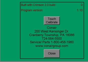
30 TGC Guillotine Cutter Control: Menu bars Menu bar 1 Menu bar 2 The menu page is the root page for screen navigation. The row of buttons at the top of the menu page allow access to specific pages. Pressing the arrow button in the Menu bar will select Menu bar #1 or Menu bar #2 Main page: Units of Measure page: Recipes page: Security page: Arrow buttons: Language: About: This will take you back to the main page. This page allows customer to set the units of measure to English or Metric. This page allows access to the recipe storage system. The current setup of the machine running parameters can be save to a recipe file. The system allows storage of 100 recipes. The running parameters can be changed by loading a saved recipe file. This page allows for changing the security settings for various functions of the TGC Guillotine. Proper login access is required to make changes to these settings. This forward button from Menu bar #1 and backward button from Menu bar #2 allow access or toggling between the two menu bars. The functions listed above are from Menu bar #1. The functions listed below are from Menu bar #2. This page allows changing the language setting of the control. This button navigates to the information page, where you can located the contact information for Conair, the current program version, and the HMI build version. This page is also the location to start a Touch Calibration procedure for calibrating the touch functionality of the screen. 4-6 l Operation
31 TGC Guillotine Cutter Control: Menu Screen Note: Depending on options ordered, modes selected, or customized settings, the screens on your TGC may not appear exactly as shown. These screens are meant to be a representation of standard screens. Timers page: Manual Functions page: This page gives the User access to the clamp delay and cut delay for the TGC Guillotine Cutter. It also includes settings for the dump table, if equipped. This page gives the User access to all manual functions of the TGC Guillotine Cutter. 4 Operation Encoder Scaling page: Control Status page: Drive Status page: Input Status page: Output Status page: This page allows access to the master encoder input scaling parameters. The TGC uses a quadrature encoder input signal to measure product length. These parameters scale encoder pulses to product length. This page allows access to the TGC control module status. The information displayed on this page would be used to help troubleshoot problems encountered with the guillotine. This page allows access to the TGC drive module status. The information displayed on this page would be used to help troubleshoot problems encountered with the guillotine. This page allows access to the TGC control digital input status. The information displayed on this page would be used to help troubleshoot problems encountered with the guillotine. This page allows access to the TGC control digital output status. The information displayed on this page would be used to help troubleshoot problems encountered with the guillotine. Operation l 4-7


32 4-8 l Operation Control Function Flow Charts
33 Control Function Flow Charts (continued) 4 Operation (Continued) Operation l 4-9
34 4-10 l Operation Control Function Flow Charts (continued)


35 Control Function Flow Charts (continued) 4 Operation (Continued) Operation l 4-11


36 4-12 l Operation Control Function Flow Charts (continued)
 Operation l 4-13")
37 Control Function Flow Charts (continued) 4 Operation (Continued) Operation l 4-13


38 4-14 l Operation Control Function Flow Chart (continued)

 4")
")
39 Control Function Flow Charts (continued) 4 Operation (Continued) Operation l 4-15


40 Control Function Descriptions Main Page The main page is displayed automatically upon power up after the system is done initializing. The main page is where most machine control functions are performed. In this sample screen, all options are shown. In your control, different options will be shown based upon which Mode you are operating in. Date and Time Pop Up Window This page displays a pop up screen with the current date and time. Touching the date and time allows the User to correct for the current date and time l Operation

41 Control Function Descriptions (continued) Mode Selection from Main This page allows you to select the mode for cutting. Modes can only be changed when the cutter is off. 4 Operation Cut Enable Turned Off Note on the above screen that the Cut enable knob selection is pointing to off. Touching the knob will rotate the selection to On. (Continued) Operation l 4-17

42 Control Function Descriptions (continued) Cut Enable Turned On Note on the above screen that the Cut enable knob selection is pointing to On. Touching the knob will rotate the selection to Off. Main In Encoder Mode Note on the above screen that the Mode is set to Encoder. Touching the text Mode: allows you to change the mode of operation for the guillotine. Available modes of operation are: Encoder, End sense, and Timer l Operation

43 Control Function Descriptions (continued) Part Counter Total From the main screen, if you touch the part counter count, this window wil pop up. From this window, you can turn part counting on or off and can reset the total count. 4 Operation Cut Length in Encoder Mode From the main screen, if you press the text Cut length: the above pop up window opens. Here you can enter the desired cut length then press the enter key. The numeric key pad will disappear after the enter key is pressed as long as the value is in the acceptable range. (Continued) Operation l 4-19

44 Control Function Descriptions (continued) Hold off delay From the main screen, in End sense mode, you can enter the amount of time you would like the photo eye or switching signals to be ignored after the cut is made. Note: you do not want to set the value too long, or you may start missing the next cut. Main In End Sense Mode This page uses a proximity switch, mechanical switch, or some type of sensing device that triggers the cut. The sensing device must be placed at a distance from the downstream side of the blade. Pressing on the Mode text will enable you to change the mode of operation between End sense, Timer, and Encoder l Operation

45 Control Function Descriptions (continued) Main In Timer Mode. In Timer mode, the guillotine uses a cycle time to determine the cut frequency. Pressing on the Mode text will enable you to change the mode of operation between End sense, Timer, and Encoder. 4 Operation Cycle Time Pop Up in Timer Mode When in Timer mode, pressing the cycle time text will display this pop up window. From here, you can adjust the cycle time. (Continued) Operation l 4-21
46 Control Function Descriptions (continued) Timers From Main Screen On the main screen in Timer mode, touching the Timers button will display the Timers Screen. From this screen, you can adjust the clamp delay, the cut delay, the dump table delay, and the dump table duration l Operation

47 Control Function Descriptions (continued) Timer Start Delay Pop Up On the main screen in Timer mode, touching the Timers button will display the Timers Screen. Pressing Start delay on this screen displays the above window to set the delay. 4 Operation (Continued) Operation l 4-23
.")
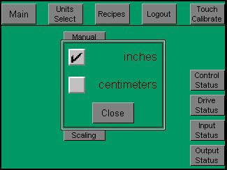
48 Control Function Descriptions (continued) Menu Page The menu page is the root page for screen navigation. Units of Measure Page Selecting inches sets length units to inches and speed units to feet/min, (FPM). Selecting centimeters sets length units to centimeters and speed units to meter/min, (MPM) l Operation

49 Control Function Descriptions (continued) Recipes Recipes Page Recipes Page The recipe page allows access to the recipe storage/retrieval system. Up to 100 recipe files are available and are number 1 thru 100. Each recipe file can be given a name up to 40 characters. Five recipe file numbers/names are displayed at once. To view other recipe file names touch the Pg Up or Pg Dn buttons. The recipe files are scrolled five at a time. 4 Operation Three recipe function can be performed. They are Load from selected, Delete selected and Save to selected. To perform one of these functions a recipe file must first be selected. To select a recipe from the recipe file, touch the name of the desired recipe from the list of five currently displayed. The recipe name and number will appear as the selected recipe file. The name of the selected recipe can be changed by touching the selected recipe name. (Continued) Operation l 4-25

50 Control Function Descriptions (continued) Recipe Name Edit Page When you touch on the name of a recipe from the Recipes page, you are able to edit the name of that recipe. From here, use the keypad to name the recipe, and press Enter when complete to return to the Recipes screen. Recipe Save Page The Save to selected function is available anytime. This function will save the active parameters to the selected recipe file l Operation


51 Control Function Descriptions (continued) Recipe Delete Page The Delete selected function is available anytime. This function will set the name of the selected recipe file to Empty. The actual parameter values in the recipe file are not deleted 4 Operation Recipe Load Page The Load from selected function is only available when the cutter is stopped. This function will load the parameters from the recipe file into the active parameters. (Continued) Operation l 4-27
52 Control Function Descriptions (continued) Manual Functions. This screen allows you to test cylinders and solenoids that operate guillotine functions for cleaning and troubleshooting. Control Status This page allows access to the TGC Guillotine control module status. The information displayed on this page would be used to help troubleshoot problems encountered with the guillotine operation l Operation

53 Control Function Descriptions (continued) Drive Status This page allows access to the TGC Guillotine module status. The information displayed on this page would be used to help troubleshoot problems encountered with the guillotine operation. 4 Operation Input Status This page allows access to the TGC Guillotine control digital input status. The information displayed on this page would be used to help troubleshoot problems encountered with switches/photo eyes, eliminating the need to meter connections in the control box. (Continued) Operation l 4-29


54 Control Function Descriptions (continued) Output Status This page allows access to the cutter servo control digital output status. The information displayed on this page would be used to help troubleshoot problems encountered. Encoder Scaling This screen is used for setting the encoder for your application depending on where you have mounted the encoder and what encoder you are using l Operation

55 Control Function Descriptions (continued) Encoder Counts Pop Up If you touch the Encoder counts text on the Encoder screen, this is the pop-up window to set the number of encoder pulses per revolution for the encoder used. The machine is set at the factory and this setting should not need changed. 4 Operation Encoder Scale Factor Pop Up This screen allows further adjustment of the encoder for your application. (Continued) Operation l 4-31

56 Control Function Descriptions (continued) Touch Calibrate Page The HMI touchscreen can be calibrated by this page. Selecting this page begins the calibration procedure. The user is guided to touch various points on the screen to complete the procedure. Touch Calibrate Success Page This message displays when you have successfully calibrated the touch screen l Operation

57 Control Function Descriptions (continued) Touch Calibrate Failure Page This message displays if the calibration has failed. This is usually because too much time has passed between touches, or there is a problem with the touch functionality of the screen. 4 Operation (Continued) Operation l 4-33

58 Control Function Descriptions (continued) Security This window will pop up anytime you are trying to access an area or change a setting that requires a higher security level. From here, you can enter your username and press the enter key. Security Username From here, you can enter your username and press the enter key l Operation
59 Control Function Descriptions (continued) Security Password From here, you can enter your password and press the enter key to access the area you were trying to access. 4 Operation (Continued) Operation l 4-35
60 The Cutter Control IMPORTANT: Always refer to the wiring diagrams that came with your guillotine before making electrical connections. The diagrams show the minimum size main power cable required for your cutter, and the most accurate electrical component information. IMPORTANT: Before applying power, ensure that the GUILLOTINE BLADE and TABLE FORWARD valves are closed (fully clockwise). 1 Connect the electrical line cord to a source of power. compatible with the nameplate on the TGC Guillotine. 2 Connect the air supply to the FRL (filter-regulator-lubricator) on the cutter. 3 Turn the main disconnect switch to the ON position. 4 Press Start or (if equipped with Dust Collector) turn Dust Collector power ON first and then press START. 5 Check the guillotine function. Make sure that the FRL is set for 65 PSI. 6 Press Manual Cut. 7 Adjust the Table Forward speed control to match the approximate line speed (if a pneumatic control is used). 8 Adjust the Table Return speed control to the suitable travel return speed (if a pneumatic control unit is used). 9 Adjust the clamp pressure regulator to grasp the profile firmly. Note: The TABLE RETURN pressure must be set high enough to return the table to the start position and trigger the TABLE START micro-switch from the front or operator side of the unit l Operation
61 Machine Frame and Support System The machine frame is constructed of welded steel that has been primed and painted to resist corrosion and provide a maintenance free finish. The frame is supported by, four leveling screws, that both permanently fix the position of the unit and also help accommodate any uneven flooring. These screws have a welded hex nut to allow adjustment with a wrench. The motors and machine components are mounted inside the frame and completely guarded for operator safety. These and all guards should always remain securely in place when machine is running and should be re-installed after any maintenance procedures that have required their removal. 4 Operation Operation l 4-37
62 Clamp Adjustment On the TGC Guillotine, the clamp cylinders will extend until contact is made with the part. The only necessary adjustments are flow controls which adjust the speed of the clamp extension and retraction, and pressure regulation to adjust the clamp force. To adjust the speed of the clamp extending and retracting: 1 Adjust the flow controls for the guillotine head, which will adjust the speed of the clamp. 2 Continue adjusting as necessary to achieve the desired result. To adjust the clamp force or pressure: 1 Adjust the pressure regulation, which will adjust the force of the clamp on the product. 2 Continue adjusting as necessary to achieve the desired result. Power Supply This equipment is powered by either 230 or 460 VAC, Three Phase, as specified on the machine nameplate. 1 Connect the machine power through a fused disconnect of proper rating. Make sure the power is grounded through the power cable to the plant electrical ground. Control Panels The operator control panels are located on the front of the cutter frame. The pneumatic control panel is located near the operator controls platform. It consists of a pressure regulator, pressure gauge, and flow controls. All items are labeled, and easily accessible l Operation
63 Pneumatic Cylinder Operation The traveling table, guillotine blade, and clamp assemblies are moved with air cylinders. The speed of the movement of the carriage assembly is controlled by flow controls located on the operator panel. Clockwise rotation will slow the table speed and counterclockwise rotation will increase the table speed. The guillotine blade is moved up and down with an air cylinder located on the table. It is controlled by the HMI.. The clamp assembly is moved up and down by air cylinders mounted above the clamp. They are controlled by flow controls mounted on the Cylinders. Clockwise rotation will slow the clamp movement speed and counterclockwise rotation will increase the clamp movement speed. The table and clamp pressure setting is adjusted with a pressure regulator located on the operator panel. The pressure level setting is displayed on the gauge located above the regulator. The table and clamp pressure should never exceed 60 PSI. The main filter/regulator/lubricator is mounted on the side of the machine near the electrical enclosure and should be maintained as described in the manufacturers documentation. This unit should always be supplied with clean dry air. Incoming pressure should be set at approximately 65 PSI. Maximum pressure is 70 PSI. 4 Operation Use the Manual Jog page to make these adjustments. IMPORTANT: This unit should always be supplied with clean dry air. Incoming pressure should be set at approximately 65 PSI. Maximum pressure is 70 PSI. Operation l 4-39
64 Electrical Operation The operation of the guillotine consists of an automatic sequence of events. See Section 1: Introduction, How to use the Lockout Device. 1 To start the TGC Cutter, the main power must be on and the appropriate air supply must be given to the machine. With the power on, the control panel will have the power light illuminated. 2 To start the cutter, push the start button. Once the cutter is started, push the yellow manual cut button and the machine will start its automatic cycle. The clamps will come down and the table will begin to travel away from its home position. Immediately after this happens, the guillotine assembly will move the blade until it reaches its up limit switch. Upon reaching this switch, the blade will return to the home position, the clamps will raise and the table will return to its home position, completing one cycle. IMPORTANT: An important reminder is that the speed settings of the pneumatic flow controls will affect the cycle time of the machine. The flow controls must be set properly to a compromise between cycle time and cut quality. Flow control settings should be adjusted at this time and fine-tuned during the initial phase of the guillotine operation l Operation
65 Machine Lubrication The machine is supplied to you completely lubricated. After running the unit for long periods of time, this lubrication will break down and become useless. Follow this lubrication chart for optimum performance. Component Type of Lubricant Duration Table Roller Bearings Chassis Lube 2-6 months System Inspection Although this unit was designed to require a minimum amount of maintenance, it should be inspected periodically to insure that it remains in top operating condition. Items to inspect are as follows: Guillotine blade - The cutter blade, will after time, begin to wear. The blade should be visually inspected for wear and replaced as necessary. Pneumatic System - Approximately once every 12 months or sooner if able, all system pneumatic components should be visually inspected. All hoses should be checked for wear or damage. All regulators and flow controls should be adjusted through their usable ranges to insure proper operation. 4 Operation Operation l 4-41
66 Blade Replacement 1 Lock out and tag out the power to the TGC Guillotine Cutter. See Section 1: Introduction, How to use the Lockout Device. 2 Wait for the blade and cylinder to stop moving completely. 3 Refer to Installing or Changing the Cutter Blade in the Installation section of this User Guide. WARNING: Electrical hazard Before performing maintenance or repairs on this product, disconnect and lock out electrical power sources to prevent injury from unexpected energization or start-up. A lockable device has been provided to isolate this product from potentially hazardous electricity. CAUTION: Moving parts Before removing lockout devices and returning switches to the ON position, make sure that all personnel are clear of the machine, tools have been removed and all safety guards are reinstalled l Operation
67 SECTION 5 Maintenance Maintenance Features Warnings and Cautions Maintenance Overview Preventative Maintenance Schedule Checking Electrical Connections Maintenance Maintenance l 5-1
68 Maintenance Features The TGC Guillotine cutter needs regular, scheduled maintenance for peak performance. Among the features that require maintenance are: Blades Blade mounting hardware Product guides The guard hardware Blade alignment Floor locks Carriage slide system Electrical cables Control panel lights Warnings and Cautions To maintain the best performance of the cutter it must be cleaned and inspected regularly. Maintenance includes a daily, weekly, quarterly, and semi-annual (every 6 months) schedule. Use this maintenance schedule as a guide. You may need to shorten the time of the maintenance schedule, depending on how often you use the guillotine cutter, and the types of material flowing through it. Follow all precautions and warnings when working on the equipment. WARNING: Improper Installation, operation, or servicing may result in equipment damage or personal injury. This equipment should only be installed, adjusted, and serviced by qualified technical personnel who are familiar with the construction, operation, and potential hazards of this type of machine. All wiring, disconnects, and fuses should be installed by qualified electrical technicians in accordance with electrical codes in your region. Always maintain a safe ground. Do not operate the equipment at power levels other than what is specified on the machine serial tag and data plate. 5-2 l Maintenance (Continued)
69 Warnings and Cautions (continued) WARNING: Voltage hazard This equipment is powered by alternating current, as specified on the machine serial tag and data plate. Do not operate the equipment at power levels other than what is specified on the machine serial tag and data plate. A properly sized conductive ground wire from the incoming power supply must be connected to the chassis ground terminal inside the electrical enclosure. Improper grounding can result in severe personal injury and erratic machine operation. Before performing maintenance or repairs on this product, disconnect and lock out electrical power sources to prevent injury from unexpected energization or start-up. A lockable device has been provided to isolate this product from potentially hazardous electricity. DANGER: Sharp Blades! Most injuries caused by knife blades occur when the cutter has been turned off. Handle blades with care at all times. Always wear cut-resistant gloves when the cutting chamber is open and when handling blades. Always lock out power to the guillotine before opening any guards. Always wait until the cutter head has completely stopped before opening the knife guard. Always wait until the blade has completely stopped before opening the guillotine guards (approximately 2 minutes.). TGC Guillotines are equipped with several safety devices to ensure safe operation. Never remove or disable these devices to sustain production. Operating without these devices can cause severe injury. 5 Maintenance Maintenance Overview This section describes the daily, weekly, monthly and semi-annual maintenance schedules that should be performed when changing materials or lines, or when changing equipment, as well as the maintenance procedures to follow. Cutting either flexible or rigid materials generates tremendous shock and vibration to the entire unit. Anything that can loosen, will over time. To maintain the best performance, follow this maintenance schedule and develop an effective preventative maintenance program. Maintenance l 5-3
70 Preventative Maintenance Schedule Daily Checking guillotine blade(s) Clean, sharpen or replace as needed (see Section 4, Blade Replacement). Inspecting the blade mounting hardware. The blade securing nuts should regularly be tightened. Inspecting the cutter product guides for wear and alignment. Inspecting cutter alignment. Proper cutter alignment is critical for optimum performance. Use a plumb line or laser to check for a straight line from the extrusion die to the guillotine guides. Check floor locks. It is always recommended that the weight be removed from the casters for optimum stability during cutting cycles. Check to see if the floor locking mechanism is properly adjusted. Weekly Blow or vacuum, dust and chips from all surfaces of the TGC. Open pneumatic and electrical enclosures and remove the dust and chips from all components. Check that the FRL (filter-regulator-lubricator) for the air input is filled with oil and that the oilier is working. Pressure should be set for around 60 PSI. This unit also has an automatic drain for any moisture that may develop. The bowl should be kept clean to ensure it will operate properly. 5-4 l Maintenance (Continued)
71 Preventative Maintenance Schedule (continued) Quarterly Blow or vacuum, dust and chips from the inside the cutter. Remove all dust and chips from inside all control cabinets. Remove any excess oil from the pneumatic enclosure. Verify that all electrical terminals are tight. Check that all air lines are in order (free of cuts or abrasions). Check that the adjustable flow controls on the BLADE UP cylinder is set for a smooth downward return. Check that the adjustable flow controls on the clamp cylinder are set so that the clamp operates quickly a slow cycle on the clamp-down will cause inaccurate cuts in length. Check the condition of the clamp pads. If worn or damaged, replace with a new set of pads. Check the condition of the clamp pads. If worn or damaged, replace with a new set of pads. Check the condition of the blade. If the blade is dull, have the blade replaced. WARNING: Electrical hazard Before performing maintenance or repairs on this product, disconnect and lock out electrical power sources to prevent injury from unexpected energization or start-up. A lockable device has been provided to isolate this product from potentially hazardous electricity. CAUTION: Moving parts Before removing lockout devices and returning switches to the ON position, make sure that all personnel are clear of the machine, tools have been removed and all safety guards are reinstalled. 5 Maintenance Maintenance l 5-5

72 Checking Electrical Connections WARNING: Electrical Hazard Before performing any work on this product, disconnect and lock out electrical power sources to prevent injury from unexpected energization or start-up. A lockable device has been provided to isolate this product from potentially hazardous electricity. WARNING: Improper Installation, operation, or servicing may result in equipment damage or personal injury. This equipment should only be installed, adjusted, and serviced by qualified technical personnel who are familiar with the construction, operation, and potential hazards of this type of machine. All wiring, disconnects, and fuses should be installed by qualified electrical technicians in accordance with electrical codes in your region. Always maintain a safe ground. Do not operate the equipment at power levels other than what is specified on the machine serial tag and data plate. 1 Be sure the main power is disconnected and the TGC is locked out. Always disconnect and lock out the main power source before opening the unit or servicing. 2 Turn the main power disconnect to the off position before opening the electrical enclosure on the back of the guillotine, or the back of the control. This is a safety device to prevent you from opening the doors if the power is still on. Main power safety disconnect 5-6 l Maintenance (Continued)
73 Checking Electrical Connections (continued) 3 Open the electrical enclosure. 4 Inspect all wires and connections. Look for loose wires, burned contacts, and signs of over-heated wires. Have a qualified electrician make any necessary repairs or replacements. 5 Close the electrical enclosure door. 6 Inspect the exterior power cords. Cords should not be crimped, exposed, or rubbing against the frame. If the main power cord runs along the floor, make sure it is not positioned where it could rest in pooling water or could be run over and cut by wheels or casters. 5 Maintenance Maintenance l 5-7
74 5-8 l Maintenance
75 SECTION 6 Troubleshooting Before Beginning A Few Words of Caution Identifying the Cause of a Problem Electrical Problems Product Quality Problems TGC Guillotine Fault Messages Checking the Servo Amplifiers Checking the Encoder Troubleshooting Troubleshooting l 6-1
76 Before Beginning You can avoid most problems by following the recommended installation, operation and maintenance procedures outlined in this User Guide. If you have a problem, this section will help you determine the cause and tell you how to fix it. Before you begin troubleshooting: Find any wiring, parts, and assembly diagrams that were shipped with your equipment. These are the best reference for correcting a problem. The diagrams will note any custom features or options not covered in this User Guide. Verify that you have all instructional materials related to the cutter. Additional details about troubleshooting and repairing specific components are found in these materials. Check that you have a manual for other equipment connected in the system. Troubleshooting may require investigating other equipment attached to, or connected with the cutter. A Few Words of Caution WARNING: Improper installation, operation or servicing may result in equipment damage or personal injury. This equipment should only be installed, adjusted, and serviced by qualified technical personnel who are familiar with the construction, operation, and potential hazards of this type of machine. All wiring, disconnects, and fuses should be installed and adjusted by qualified electrical technicians in accordance with electrical codes in your region. Always maintain a safe ground. Do not operate the equipment at power levels other than what is specified on the machine serial tag and data plate. WARNING: Electrical hazard. Before performing maintenance or repairs on this product, disconnect and lock out electrical power sources to prevent injury from unexpected energization or start-up. A lockable device has been provided to isolate this product from potentially hazardous electricity. 6-2 l Troubleshooting
77 A Few Words of Caution (continued) DANGER: Sharp Blades! Most injuries caused by knife blades occur when the cutter has been turned off. Handle blades with care at all times. Always wear cut-resistant gloves when the cutting chamber is open and when handling blades. Always lock out power to the cutter before opening the cutting chamber. Always wait until the guillotine has completely stopped before opening the cabinet door. TGC Guillotine Cutters are equipped with several safety devices to ensure safe operation. Never remove or disable these devices to sustain production. Operating without these devices can cause severe injury. 6 Troubleshooting Troubleshooting l 6-3
78 Identifying the Cause of a Problem The Troubleshooting section covers problems directly related to the operation and maintenance of the TGC Guillotine Cutter. This section does not provide solutions to problems that originate with other equipment. Additional troubleshooting help can be found in manuals supplied with the other equipment. The main problems you could encounter with the TGC are: Cutter operation problems, which focus on problems that are clearly related to the operation of the cutter s electrical control systems. Plastic product quality concerns, which deal with product characteristics that may be related to cutter operation. Of course, other sections of the extrusion line also influence the quality of the extruded product. This section does not provide solutions to problems originating with other equipment on the extrusion line. Additional troubleshooting help can be found in the documentation manuals included with this User Guide. 6-4 l Troubleshooting
79 Electrical Problems Look in this section when you have problems such as lights on the control that are working improperly, buttons that do not execute the function properly, and when information input is not executed properly. Symptom Possible Cause Solution TGC will not start. The E-stop button is depressed. Make sure the E-stop is extended. Disconnect in the off position. Turn disconnect to the on position. 6 Troubleshooting Troubleshooting l 6-5
80 Product Quality Problems Symptom Cut not square. Crack or fractures in cut surfaces. General poor cut quality. Possible Cause Product guides not aligned square to the blade face. Blade up speed too fast. Incorrect blade design. Incorrect cooling of extrudate. Incorrect blade design. Solution Re-align the product guides. Ensure that the rear guide is square with the blade and tighten. Adjust the front guide accordingly allowing enough clearance for smooth product passage. Adjust speed control for blade feed into part (slower). Investigate blade choice for the application. Improve the molecular structure with variation of cooling time or temperature. Investigate blade choice for the application. Product melting at cut. Dull Blade. Have blade sharpened or replaced. Blade up speed too slow. Incorrect blade design. Adjust speed control for blade feed into part (faster). Investigate blade choice for the application. 6-6 l Troubleshooting
81 Product Quality Problems (continued) Symptom Incorrect cut length. Possible Cause Encoder or input device problem. Puller problem. Solution Check encoder or input device. Check puller for drive consistencies or any belt to product slippage. Counter problem. Check cut length counter. Cutter clamps not holding. Adjust clamp pressure. Inspect clamp tooling for wear or damage. Table motion inconsistent. Roller ways dirty. Clean roller ways. Rodless cylinder problem. Check and clean rodless cylinder. Solenoid problem. Check table actuation solenoid for proper operation. Low air pressure. Check main system regulator for incoming air pressure settings. 6 Troubleshooting Troubleshooting l 6-7
82 TGC Guillotine Fault Messages Symptom 0. No message. 1. The emergency stop circuit has been activated. 2. A table overtravel was detected. Possible Cause Release the emergency stop buttons and close the guard doors. Table position was not correct for cutting process. Solution Press the emergency stop reset pushbutton. Plc input 1 must be on. Adjust settings to complete the cut sooner. 6-8 l Troubleshooting
83 Checking the Servo Amplifier The servo amplifier is equipped with a digital readout that can be seen through the viewing window on the electrical enclosure. This display shows amplifier status and error messages. Refer to the supplier's documentation included with this User Guide. NOTE: Make sure you look for servo amplifier messages before you shut off the power. Checking the Encoder When the encoder is working properly, the measurement displayed will count up to the preset and reset to zero. 1 Check all connections. 2 Check the encoder cable for damage. If necessary, replace. 3 Check the connector that attaches the cable to the encoder. Internal wiring may be shorted out if this connector is not handled properly. 4 Check the encoder itself. There should be no play in the shaft. WARNING: Delicate equipment The encoder is a delicate piece of equipment. Any rough handling can damage fragile parts. 5 If all else fails, contact Conair Customer Service. See Appendix A. Troubleshooting l 6-9
84 6-10 l Troubleshooting

85 We re Here to Help Conair has made the largest investment in customer support in the plastics industry. Our service experts are available to help with any problem you might have installing and operating your equipment. Your Conair sales representative also can help analyze the nature of your problem, assuring that it did not result from misapplication or improper use. How to Contact Customer Service To contact Customer Service personnel, call: Additional manuals and prints for your Conair equipment may be ordered through the Customer Service or Parts Department for a nominal fee. Most manuals can be downloaded free of charge from the product section of the Conair website. service is available at the same phone number. From outside the United States, call: You can commission Conair service personnel to provide on-site service by contacting the Customer Service Department. Standard rates include an on-site hourly rate, with a one-day minimum plus expenses. NOTE: Normal operating hours are 8:00 am - 5:00 pm EST. After hours emergency Before You Call... If you do have a problem, please complete the following checklist before calling Conair: Make sure you have all model, control type from the serial tag, and parts list numbers for your particular equipment. Service personnel will need this information to assist you. Make sure power is supplied to the equipment. Make sure that all connectors and wires within and between control systems and related components have been installed correctly. Check the troubleshooting guide of this manual for a solution. Thoroughly examine the instruction manual(s) for associated equipment, especially controls. Each manual may have its own troubleshooting guide to help you. Check that the equipment has been operated as described in this manual. Check accompanying schematic drawings for information on special considerations. Appendix l A-1
TS Series Up Cut Saw. Models TS524 UP, TS724 UP, and TS924 UP USER GUIDE UGE
 USER GUIDE UGE072-1113 www.conairgroup.com TS Series Up Cut Saw Models TS524 UP, TS724 UP, and TS924 UP Corporate Office: 724.584.5500 l Instant Access 24/7 (Parts and Service): 800.458.1960 l Parts and
Traveling Saw CTS Models 5, 7 and 9
 www.conairgroup.com USER GUIDE Traveling Saw CTS Models 5, 7 and 9 Corporate Office: 724.584.5500 Instant Access 24/7 (Parts and Service): 800.458.1960 Parts and Service: 814.437.6861 Please record your
Combination Puller/Cutter
 USER GUIDE UGE070-0612 www.conairgroup.com Combination Puller/Cutter CPC Model Corporate Office: 724.584.5500 l Instant Access 24/7 (Parts and Service): 800.458.1960 l Parts and Service: 814.437.6861 Please
Precision Belt Puller Series
 U S E R G U I D E UGE015-1015 www.conairgroup.com Precision Belt Puller Series Models: 3-20, 4-26, 6-39 Corporate Office: 724.584.5500 l Instant Access 24/7 (Parts and Service): 800.458.1960 l Parts and
Record your equipment s model and serial number(s) and the date you received it in the spaces provided.
 and the date you received it in the spaces provided.") Record your equipment s model and serial number(s) and the date you received it in the spaces provided. It is important to record the model and serial number(s) of your equipment and the date you received
Record your equipment s model and serial number(s) and the date you received it in the spaces provided. It is important to record the model and serial number(s) of your equipment and the date you received
PC Series Cleated Pullers
 PC Series Cleated Pullers PC-8, PC-10, PC-12 and PC-18 Installation Operation Maintenance Troubleshooting Instant Access Parts and Service (800) 458-1960 (814) 437-6861 www.conairnet.com The Conair Group,
MedLine Combination Puller/Cutter
 USER GUIDE UGE064-0217 www.conairgroup.com MedLine Combination Puller/Cutter (Shown with some optional equipment) Corporate Office: 724.584.5500 l Instant Access 24/7 (Parts and Service): 800.458.1960
RG Series Pumps U S E R G U I D E UGC
 U S E R G U I D E UGC025-1208 www.conairgroup.com RG Series Pumps Corporate Office: 724.584.5500 l Instant Access 24/7 (Parts and Service): 800.458.1960 l Parts and Service: 814.437.6861 Please record
Adjustable Purge Valve
 U S E R G U I D E UGC031-0508 www.conairgroup.com Adjustable Purge Valve Single and Dual APV Models Corporate Office: 724.584.5500 l Instant Access 24/7 (Parts and Service): 800.458.1960 l Parts and Service:
OPERATING INSTRUCTIONS IC-2, 3,4,5,6 INTELLICUT SERVO CUTTER Version 5.1xx Created 11/2009
 OPERATING INSTRUCTIONS IC-2, 3,4,5,6 INTELLICUT SERVO CUTTER Version 5.1xx Created 11/2009 "CAUTION" "DO NOT OPERATE MACHINE WITH GUARD REMOVED" UNCRATE AND INSPECT This machine has been carefully crated
OPERATING INSTRUCTIONS IC.25,.5, 1, 2, 3, 4, 5 & 6 INTELLICUT COMBINATION SERVO PULLER/CUTTER Ver. 5.1xx
 OPERATING INSTRUCTIONS IC.25,.5, 1, 2, 3, 4, 5 & 6 INTELLICUT COMBINATION SERVO PULLER/CUTTER Ver. 5.1xx "CAUTION" "DO NOT OPERATE MACHINE WITH GUARD REMOVED" UNCRATE AND INSPECT This machine has been
Model 1100B CHG Terminator. Installation Instructions
 Model 1100B CHG Terminator Installation Instructions 1 Contents: 1.0 Safety Information... 3 2.0 Set-up and Adjustments... 3 3.0 Ram Adjustments... 10 4.0 Wire Termination Quality... 12 5.0 General Maintenance...
Cyclone 600 Upcut Cut Off Saw
 Cyclone 600 Upcut Cut Off Saw WARNING The operator must thoroughly read and understand this manual before operating the cut off saw or starting any servicing. All safety and warning instructions should
TERMINATOR User Manual
 TERMINATOR User Manual TERMINATOR User Manual Table of Contents Section Page 1 2 3 4 5 6 7 8 9 10 11 12 13 14 15 16 17 18 19 20 21 Introduction Safety Precautions Features and Benefits Overview of the
Positive Displacement Pump
 www.conairgroup.com U S E R G U I D E UGC028-1105 Positive Displacement Pump Models PD 3. 5, 7.5, 10, 15 and 25 Corporate Office: 724.584.5500 l Instant Access 24/7 (Parts and Service): 800.458.1960 l
Opera ons & Parts Manual VersaClipper 3100
 Opera ons & Parts Manual VersaClipper 3100 Heavy Duty Servo Driven & Computer Controlled Fully Automa c and Highly Versa le Clip A aching Machine Model #3100 Serial # 1 Revised 09/21/17 Table of Contents
MX Sprue Pickers with CD-EM1 control
 MX Sprue Pickers with CD-EM1 control Models MX60 to MX550, and MX350T to MX550T Installation Operation Maintenance Troubleshooting Instant Access Parts and Service (800) 458-1960 (814) 437-6861 www.conairnet.com
MPT-250B SPECIFICATIONS AND OPERATING INSTRUCTIONS
 1. SAFETY The MPT-250B Wire Crimp Pull Tester is a force measurement device, and as such should be operated with due caution. Operators should wear safety glasses for eye protection because the crimp under
OPERATING INSTRUCTIONS TT-.5/206-1 BUBBLE TUBE COMBINATION PULLER/CUTTER
 OPERATING INSTRUCTIONS TT-.5/206-1 BUBBLE TUBE COMBINATION PULLER/CUTTER "CAUTION" "DO NOT OPERATE MACHINE WITH GUARD REMOVED" UNCRATE AND INSPECT This machine has been carefully crated to assure safe
INSTALLATION MANUAL. Fendt VarioGuide Ready COM 3 Supported Models PN REV A
 INSTALLATION MANUAL Fendt VarioGuide Ready COM 3 Supported Models 922 924 927 930 933 936 PN 602-0264-02 REV A LEGAL DISCLAIMER Note: Read and follow ALL instructions in this manual carefully before installing
Automatic Sliding Door Retrofit Drive Assembly. Installation Manual DoorControlsUSA.com
 Automatic Sliding Door Retrofit Drive Assembly Installation Manual 800-437-3667 DoorControlsUSA.com TABLE OF CONTENTS pg. 1. COMPONENTS 2 2. HEADER PREPARATION 2 3. DOOR PREPARATION 2 4. MOTOR AND CONTROLLER
Installation, Operation and Maintenance Manual
 Document 473681 Vari-Green Motor and Controls Installation, Operation and Maintenance Manual Please read and save these instructions for future reference. Read carefully before attempting to assemble,
Installation, Operation and Maintenance Manual
 Document 47681 Vari-Green Motor and Controls Installation, Operation and Maintenance Manual Please read and save these instructions for future reference. Read carefully before attempting to assemble, install,
Installation, Operation and Maintenance Manual
 Document 473681 Vari-Green Motor and Controls Installation, Operation and Maintenance Manual Please read and save these instructions for future reference. Read carefully before attempting to assemble,
IDEAL Stripmaster Model 950 Wire Stripper #45-950
 IDEAL Stripmaster Model 950 Wire Stripper #45-950 IDEAL Stripmaster Model 950 Wire Stripper Introduction The IDEAL Stripmaster Model 950 Wire Stripper is an electrically operated, pneumatic precision production
RolsplicerTM. Maintenance Manual And Illustrated Parts List
 RolsplicerTM Maintenance Manual And Illustrated Parts List List of Illustrations Figure Page. Rolsplicer 3 2. Roller Adjustment 4 3. Rolsplicer 6 4. Lid Hold Down Assembly 8 5. Automatic Lid Speed Adjustment
OEM TM-50 Quick Start Guide
 This quick start guide provides basic setup and operating instructions for the OEM TM-50. The intended use of the OEM TM-50 Taping Machine is to produce taped reels of individually sealed and consistently
Declaration of Conformity
 Declaration of Conformity We, Manufacturer: Spartanics Ltd. 3605 Edison Place Rolling Meadows, Illinois 60008 Phone: 847-394-5700 Fax: 847-394-0409 USA ENGLISH declare under our sole responsibility that
PREPOINT CHAMFER GRINDER MODEL Section 1. Set up and operation
 PREPOINT CHAMFER GRINDER MODEL 6-94 Set up and operation Section 1 1. Installation of the proper size collet. This machine used a 5-C style collet. This can be changed by loosening of he set screw located
TLA Model Tube Loaders
 USER GUIDE UGC013/1003 TLA Model Tube Loaders Hopper Loading, Feeding Bin and Direct Feed Configurations www.conairnet.com Hopper Loading Feeding Bin Direct Feed DESCRIPTION Typical applications Features
EB Conveyor Maintenance Guide
 EB Conveyor Maintenance Guide EN-0037 Rev A EB Conveyor Maintenance Guide www.qdraw.com Table of Contents Overview Page 3 Exploded View Of A Standard EB Conveyor Page 4 Preventative Maintenance Page 5
World Leaders in Diesel Fuel Injection Test Equipment. IFT-c. Injector Function Tester Controller. Operating and Servicing Manual
 World Leaders in Diesel Fuel Injection Test Equipment. IFT-c Injector Function Tester Controller Operating and Servicing Manual HL048 (EN) Issue 4, H1852, August 2011 HARTRIDGE LIMITED IFT-c Operating
IMPORTANT! DO NOT THROW AWAY THE SHIPPING CARTON AND PACKING MATERIAL
 Operator s Manual IMPORTANT! DO NOT THROW AWAY THE SHIPPING CARTON AND PACKING MATERIAL ii Table of Contents Operator Safety... 1 Introduction... 2 Unpacking and Setup... 3 Unpacking... 3 Setup... 4 ROCKET
Intelli-Feed Controller User s Manual Intelli-Feed Digital Tachometer and Hourmeter
 Intelli-Feed Controller User s Manual Intelli-Feed Digital Tachometer and Hourmeter Part #: 9047 Table of Contents: Table of Contents 2 Intelli-Feed TM User Interface 3 Equipment Diagnostic Indicators
5000TOC Sensor Service Manual
 Part No. 84449 5000TOC Sensor Service Manual This document contains proprietary information, which is protected by copyright. All rights are reserved. No part of this document may be photocopied (other
Operations Manual Eagle 1000 Series Stretch Wrapper
 Operations Manual Eagle 1000 Series Stretch Wrapper Models A & B - 1 - READ ALL INSTRUCTIONS CONTAINED IN THIS MANUAL PRIOR TO MACHINE INSTALLATION! - 2 - Contents page 1. Machine Safety Information 1.1
Water / Spray Tanks WT and ST Series Models
 www.conairgroup.com USER GUIDE Water / Spray Tanks WT and ST Series Models Corporate Office: 724.584.5500 Instant Access 24/7 (Parts and Service): 800.458.1960 Parts and Service: 814.437.6861 Please record
Installation Instructions
 H068A00 H069A00 H070A00 POWER EXHAUST ACCESSORY SINGLE PACKAGE ROOFTOP UNITS 12.5to25TONS Installation Instructions TABLE OF CONTENTS SAFETY CONSIDERATIONS... 1 GENERAL... 1 INSTALLATION... 2 Power Exhaust
Access Loader with Easy Loading Control (ELC)
") U S E R G U I D E UGC023-1208 www.conairgroup.com Access Loader with Easy Loading Control (ELC) Models AL2 and AL5 Corporate Office: 724.584.5500 l Instant Access 24/7 (Parts and Service): 800.458.1960
U S E R G U I D E UGC023-1208 www.conairgroup.com Access Loader with Easy Loading Control (ELC) Models AL2 and AL5 Corporate Office: 724.584.5500 l Instant Access 24/7 (Parts and Service): 800.458.1960
HAYWARD FLOW CONTROL TBH SERIES TRUE UNION BALL VALVE INSTALLATION, OPERATION AND MAINTENANCE INSTRUCTIONS
 HAYWARD FLOW CONTROL TBH SERIES TRUE UNION BALL VALVE INSTALLATION, OPERATION AND MAINTENANCE INSTRUCTIONS Pg. 1 of 10 PLEASE READ THE FOLLOWING INFORMATION PRIOR TO INSTALLING AND USING HAYWARD TBH SERIES
IMPORTANT ATTENTION INSTALLERS:
 Power Exhaust Kit for P7TQ, Q7TQ & R7TQ Series INSTALLATION INSTRUCTIONS IMPORTANT ATTENTION INSTALLERS: It is your responsibility to know this product better than your customer. This includes being able
EV-2051-M Electric Motor. Operation and Maintenance Manual
 EV-2051-M Electric Motor Operation and Maintenance Manual Table of Contents Safety... 3 General...3 Safety Notices...6 Cautions, Warnings and Dangers...7 Cautions...8 Warnings...11 Dangers...13 Important
DeZURIK DR 40B ROTARY DIAPHRAGM ACTUATOR
 DR 40B ROTARY DIAPHRAGM ACTUATOR Instruction D10506 October 2016 Instructions These instructions provide information about s. They are for use by personnel who are responsible for installation, operation
SERVICE MANUAL (DOMESTIC & INTERNATIONAL)
") SERVICE MANUAL (DOMESTIC & INTERNATIONAL) DUAL TECHNOLOGY FINISHER MODEL 1960 & 1980 SERIES Lincoln Foodservice Products, LLC 1111 North Hadley Road Fort Wayne, Indiana 46804 United States of America Telephone:
SERVICE MANUAL (DOMESTIC & INTERNATIONAL) DUAL TECHNOLOGY FINISHER MODEL 1960 & 1980 SERIES Lincoln Foodservice Products, LLC 1111 North Hadley Road Fort Wayne, Indiana 46804 United States of America Telephone:
Installation. Part A, Section 3. This section covers the following unit configurations. Voltage 1, 2, 3. Vista Standard (V) A3EN-04-[3V-A-AAXV]-11
![Installation. Part A, Section 3. This section covers the following unit configurations. Voltage 1, 2, 3. Vista Standard (V) A3EN-04-[3V-A-AAXV]-11](/thumbs/87/95082297.jpg "Installation. Part A, Section 3. This section covers the following unit configurations. Voltage 1, 2, 3. Vista Standard (V) A3EN-04-[3V-A-AAXV]-11") Part A, Section 3 This section covers the following unit configurations. Model All Voltage 1, 2, 3 Pump All Manifold All Control Vista Standard (V) A 3-0 A 3-1 Section A 3 WARNING: Allow only qualified
Part A, Section 3 This section covers the following unit configurations. Model All Voltage 1, 2, 3 Pump All Manifold All Control Vista Standard (V) A 3-0 A 3-1 Section A 3 WARNING: Allow only qualified
SENTRY ISOBUS Tip Flow Monitor. Software Version 1.00
 SENTRY 6141 U S E R M A N U A L ISOBUS Tip Flow Monitor Software Version 1.00 Copyrights 2016 TeeJet Technologies. All rights reserved. No part of this document or the computer programs described in it
INTRODUCTION 2EZHM DESCRIPTION
 INTRODUCTION In order to achieve maximum production and reliability from this system, it is necessary to be familiar with its capabilities. Knowledge of installation, components and set up are essential
Agilent G3969A Transfer Line Interface for an Agilent 7697A HS Accessory
 Agilent G3969A Transfer Line Interface for an Agilent 7697A HS Accessory For the Agilent Intuvo 9000 Gas Chromatograph Installation Instructions Parts Supplied Table 1 Parts supplied with an Agilent G3969A
AC Irrigation and Propagation Controllers I Four Station, 5006-I and 5006-IP Six Station
 AC Irrigation and Propagation Controllers 5004-I Four Station, 5006-I and 5006-IP Six Station I N S T R U C T I O N M A N U A L Table of contents Introduction 1 1. Specifications 1 2. Controller Mounting
Vertical Vinyl Curtain Door
 Vertical Vinyl Curtain Door Face Mount Installation Instructions System Overview: Your Aleco Vinyl Vertical Curtain Door is a high quality, high performance flexible door system based on proven components
NECO Pumping Systems
 INSTALLATION OPERATION & MAINTENANCE INSTRUCTIONS For Your NECO Pumping Systems PACKAGED CIRCULATING SYSTEM THIS COMPLETELY ASSEMBLED, TESTED, PACKAGED CIRCULATING SYSTEM IS OF THE HIGHEST QUALITY AND
OWNERS REFERENCE MANUAL
 JECTOR CONTAINER EJECT SYSTEM ML0068-001-02 OWNERS REFERENCE MANUAL Enercon Industries Corp. W140 N9572 Fountain Blvd. P.O. Box (53052-0773) Menomonee Falls, WI 53051 Phone: (262) 255-6070 Fax: (262) 255-7784
Inteli-Lift GEN II DUMBWAITER
 1 877-345-4387 530-295-4900 www.eilifts.com Inteli-Lift GEN II DUMBWAITER The Easiest Dumbwaiter system on the Market Fully UL Certified Dumbwaiter Systems UL File # SA32120 This manual will cover the
Job Sheet 5 Hydraulic Unit Circuit
 Job Sheet 5 Hydraulic Unit Circuit The key components involved in the cylinder piston rod actuation (solenoid valves SV1, SV2, SV3A, and SV3B) are within the core components of the hydraulic unit of the
XR Conveyor Maintenance Guide
 XR Conveyor Maintenance Guide EN-0035 Rev. A XR Conveyor Maintenance Guide www.qdraw.com Table of Contents 05/20/2009 Overview Page 3 XR Conveyor Assembly Page 4 General Information Exploded View of an
Exercise 1-1. Lockout/Tagout Procedure EXERCISE OBJECTIVE DISCUSSION. Become familiar with the Industrial Controls Training System.
 Exercise 1-1 Lockout/Tagout Procedure EXERCISE OBJECTIVE Become familiar with the Industrial Controls Training System. Understand and perform proper lockout/tagout procedures during industrial servicing
Intelligent torque meter tester
 Intelligent torque meter tester Before using this product, please read the instructions carefully, which will help improve the efficiency of your use of this product Contents 一 About HP Series Torque Meter...2
Precision Pulling and Cutting for Medical Tubing Products
 Precision Pulling and Cutting for Medical Tubing Products Conair s extensive experience in medical grade extrusion equipment offers processors a wide selection of precision pulling and cutting equipment
DAKE / JOHNSON VERTICAL BAND SAW
 DAKE / JOHNSON VERTICAL BAND SAW Model F - 6 INSTRUCTION MANUAL MODEL:F-6 SERIAL NUMBER: DATE PURCHASED: Need band saw blades? Call Dake DAKE (Division of JSJ) 724 Robbins Road Grand Haven, Michigan 4947
200 Shadylane Drive Philipsburg, PA Phone: (814) Fax: (814) Service Manual. Model 642E Centrifuge
 Fax: (814) Service Manual. Model 642E Centrifuge") 200 Shadylane Drive Philipsburg, PA 16866 Phone: (814) 342-6205 Fax: (814) 342-4510 www.druckerdiagnostics.com Service Manual Model 642E Centrifuge MODEL 642E SERVICE MANUAL REV: Original Issue 1 CONTENTS
200 Shadylane Drive Philipsburg, PA 16866 Phone: (814) 342-6205 Fax: (814) 342-4510 www.druckerdiagnostics.com Service Manual Model 642E Centrifuge MODEL 642E SERVICE MANUAL REV: Original Issue 1 CONTENTS
TSS Tool Stand. Installation and Operation Manual. Document #:
 TSS Tool Stand Installation and Operation Manual Document #: 9610-20-1068 Engineered Products for Robotic Productivity Pinnacle Park 1031 Goodworth Drive Apex, NC 27539 Tel: +1-919.772.0115 Fax: +1-919.772.8259
Access Loader USER GUIDE UGC023/0305. Models AL2 and AL5
 USER GUIDE UGC023/0305 www.conairnet.com Access Loader Models AL2 and AL5 INTRODUCTION Purpose of the User Guide How the guide is organized Your responsibilities as a user ATTENTION: Read this so no one
Your Global Flow Control Partner. Series 70 24V On/Off Electric Actuator Operation and Maintenance Manual
 Your Global Flow Control Partner Series 70 Table of Contents 1. Definition of Terms.......................................2 2. Safety............................................. 2 3. Storage............................................2
AUTOMATIC SPINDLE CAPPER
 OPERATIONS MANUAL AUTOMATIC SPINDLE CAPPER (Shown above in one of several configurations.) 3999 East Hupp Road, Bldg. R-43 Phone: 219-393-3600 La Porte, IN 46350 Fax: 219-393-5260 www.liquidpackagingsolution.com
i n s t r u c t i o n m a n u a l
 i n s t r u c t i o n m a n u a l 8006 Six-Station AC Timer Residential/Light Commercial Independent Program Irrigation Controllers Installation, Programming and Operating Instructions Features Operates
RT404-FLEX II ROTARY TABLE OPERATING MANUAL
 P/N 561447 REV E AUG. 03 REV D NOV. 01 REV C APR. 01 REV B JULY 98 REV A AUG. 97 AUGUST 2003 RT404-FLEX II ROTARY TABLE OPERATING MANUAL 2003 I&J FISNAR INC. RT404-FLEX II ROTARY TABLE NOTE: Unlike the
Vertical Vinyl Curtain Door
 Vertical Vinyl Curtain Door Face Mount Installation Instructions System Overview: Your Aleco Vinyl Vertical Curtain Door is a high quality, high performance flexible door system based on proven components
ECLIPSE Laundry Dispenser Controller
 ECLIPSE Laundry Dispenser Controller Reference Manual Programming and Operation Online and downloadable Product Manuals and Quick Start Guides are available at www.hydrosystemsco.com Please check online
Vacuum Transport. Manual
 Vacuum Transport Manual 2018 Streamfeeder - BW Integrated Systems. All rights reserved. No part of this publication may be reproduced, photocopied, stored on a retrieval system, or transmitted without
HANDY GATE ASSEMBLY, INSTALLATION AND OPERATING INSTRUCTIONS
 ASSEMBLY, INSTALLATION AND OPERATING INSTRUCTIONS BEFORE INSTALLING OR USING THE, REVIEW THE VEHICLE LOADING LIMITATIONS OUTLINED IN THE VEHICLE OWNER S MANUAL AND THE SAFETY COMPLIANCE CERTIFICATION LABEL
6 Gauge Box Set IS0333
 Caution 6 Gauge Box Set IS0 Rev. B ecr 882 9/202 Disconnect the battery during installation. Tighten nuts on the back clamp only slightly more than you can tighten with your fingers. Six inch-pounds of
Techcon Systems TS6500 CIM Automatic Techkit Mixer
 Techcon Systems TS6500 CIM Automatic Techkit Mixer User Guide English Copyright OK International 7000-2860_F 1 CONTENTS Page Number 1. Safety..3 2. Unpacking and Inspection.3 3. Description 4 4. Symbol
PRODUCT INFORMATION BULLETIN #3365 DIGITAL MOTOR CONTROL PLATTER SYSTEMS For Serial Number and After
 PRODUCT INFORMATION BULLETIN #3365 DIGITAL MOTOR CONTROL PLATTER SYSTEMS For Serial Number 28640996 and After Record Platter System Identification Numbers Here: Model # Serial # Table of Contents Program
Installation, Operation and Maintenance Manual
 Document 47681 Vari-Green Motor and Controls Installation, Operation and Maintenance Manual Please read and save these instructions for future reference. Read carefully before attempting to assemble, install,
Installation and Service Manual
 RESIDENTIAL PLATFORM LIFTS RPL400 / RPL600 Installation and Service Manual WARNING! STRICT ADHERENCE TO THESE INSTALLATION INSTRUCTIONS IS REQUIRED to promote the safety of those installing this product,
Instruction Sheet 1 1/8 HP TITAN PUMPS SAFETY FIRST
 Instruction Sheet 1 1/8 HP TITAN PUMPS L1824 Rev. D 06/04 1.0 IMPORTANT RECEIVING INSTRUCTIONS Visually inspect all components for shipping damage. Shipping damage is not covered by warranty. If shipping
STYLE 9300 FLOW/PRESSURE METER INSTALLATION & OPERATING INSTRUCTIONS
 STYLE 9300 FLOW/PRESSURE METER INSTALLATION & OPERATING INSTRUCTIONS INTRODUCTION The Style 9300 Flow/Pressure Meter from Akron is designed to offer reliable and accurate service with an easy to install,
1 2 3a 3b THREADING CARD 9 10 ABC Office
 1 2 3a 3b 4 5 6 7 8 9 10 THREADING CARD Important Safety instructions YOUR SAFETY AS WELL AS THE SAFETY OF OTHERS IS IMPORTANT TO GBC. IN THIS INSTRUCTION MANUAL AND ON THE PRODUCT ARE IMPORTANT SAFETY
Easy Packer. Industrial Case Erecting, Packing and Taping System. User Guide
 Easy Packer Industrial Case Erecting, Packing and Taping System User Guide Easy Packer Industrial Case Erecting, Packing and Taping System User Guide Revised 04/19/2012 P/N XXXXXXX Rev A Copyright and
AIR CLEANERS Model MC 3000 OWNER S MANUAL CAUTION Read complete instructions before operating. Please file for future reference.
 AIR CLEANERS Model MC 3000 OWNER S MANUAL CAUTION Read complete instructions before operating. Please file for future reference. MODEL MC 3000 SPECIFICATION Input Volts: 208-230/430 VAC, 60Hz, 3 Phase
BFS and BFH Feeder ADDITIVE METERING UNIT
 USER GUIDE UGB010/1211 BFS and BFH Feeder ADDITIVE METERING UNIT www.conairgroup.com Corporate Office: 724.584.5500 l Instant Access 24/7 (Parts and Service): 800.458.1960 l Parts and Service: 814.437.6861
Hollister-Whitney Elevator Corporation
 Hollister-Whitney Elevator Corporation Installation and Service Manual GL101, GL131, GL171, GL130A, GL185 and GL260 AC Permanent Magnet, Gearless Machines Page 1 of 32 Table of Contents I. Introduction
COMPACT GLYCOL FEED SYSTEMS OPERATION & MAINTENANCE MANUAL
 COMPACT GLYCOL FEED SYSTEMS OPERATION & MAINTENANCE MANUAL Model Number: Service: Serial Number: Installation Date: Installation Location / Application: PLEASE RECORD THE FOLLOWING DATA (Information is
Low Profile Wrenches Operation and Maintenance Manual
 Low Profile Wrenches Operation and Maintenance Manual http://www.torquetoolsinc.com Use the HEXPRO Series Low Profile Wrenches Model 2HP 4HP 8HP 14HP 30HP to install and remove large bolts that have minimal
Series 70 24V On/Off Electric Actuator Operation and Maintenance Manual
 Series 70 Operation and Maintenance Manual TABLE OF CONTENTS 1. Definition of Terms............................................. 1 2. Safety................................................... 1 3. Storage..................................................
BL7000 SYSTEM OPERATING MANUAL
 BL7000 SYSTEM OPERATING MANUAL REV 2.0 208 / 230V COPYRIGHT 1995 Xenotech, Inc. PAGE 1 POWER INPUT CONNECTOR WIRING INSTRUCTIONS THE INPUT POWER REQUIREMENTS FOR A 7 KW POWER SUPPLY ARE AS FOLLOWS. VOLTAGE
FTFR Maintenance and Parts Manual SQ-1 FLOOR TRUSS FINISH ROLLER. Operators Manual
 FTFR Maintenance and Parts Manual SQ-1 FLOOR TRUSS FINISH ROLLER Operators Manual FOREWORD This manual explains the proper maintenance of Square 1 Design Floor Truss Finish Roller as well as the daily
SentryGOLD Compact. for Bennett Electronic Dispenser INSTALLATION MANUAL. Fuel Management System
 Fuel Management System SentryGOLD Compact for Bennett Electronic Dispenser INSTALLATION MANUAL 2901 Crescent Drive Tallahassee, FL 32301 (850) 878-4585 office (850) 656-8265 fax www.trakeng.com support@trakeng.com
Sterling Coilmaster JR TS Issue 3 July 2017
 Sterling Coilmaster JR TS Issue 3 July 2017 CMjr TS Operator s Training Manual Issue 3 1 P a g e 1. Important Safety Notice!...3 2. Placing the CMjr in the Proper Location...4 3. Preparing the CMjr for
ARC 1850 LIST OF FIGURES
 PAGE 1.0 INTRODUCTION... 1 2.0 WARRANTY... 1 3.0 UNPACKING YOUR UNIT... 1 4.0 SUGGESTED SAFETY PRECAUTIONS...... 1 4.1 PERSONAL SAFETY PRECAUTIONS. 1 4.2 POWER SUPPLY SAFETY PRECAUTIONS.. 2 5.0 GENERAL
Installation Instructions
 Installation Instructions MX3635-01 Rev. E Models HydraSwing 40s HydraSwing 40F 4,000 lb (1,814 kg) 10-15 seconds HydraSwing 40 4,000 lb (1,814 kg) 15-20 seconds HydraSwing 40 Twin 4,000 lb (1,814 kg)/leaf
TWO-STAGE HYDRAULIC PUMP. RWP55-IBT-Air
 ORIGINAL INSTRUCTIONS Form No.1000458 5 SPX Corporation 5885 11th Street Rockford, IL 61109-3699 USA Tech. Services: (800) 477-8326 Fax: (800) 765-8326 Order Entry: (800) 541-1418 Fax: (800) 288-7031 Internet
HexPro Series Low Profile Wrenches
 HexPro Series Low Profile Wrenches Operation and Maintenance Manual Model 2HP 4HP 8HP 14HP 30HP www.torquetoolsinc.com Use the HEXPRO Series Low Profile Wrenches Model 2HP 4HP 8HP 14HP 30HP to install
PRSalpha Air Drill (Double Valve)
") 888-680-4466 ShopBotTools.com PRSalpha Air Drill (Double Valve) Copyright 2016 ShopBot Tools, Inc. page 1 Copyright 2016 ShopBot Tools, Inc. page 2 Table of Contents Overview...5 Spindle Mounting Plate...6
888-680-4466 ShopBotTools.com PRSalpha Air Drill (Double Valve) Copyright 2016 ShopBot Tools, Inc. page 1 Copyright 2016 ShopBot Tools, Inc. page 2 Table of Contents Overview...5 Spindle Mounting Plate...6
Important. Contents. Contact us:
 Operator's Manual Third Edition Third Printing Important Read, understand and obey these safety rules and operating instructions before operating this machine. Only trained and authorized personnel shall
Motor. Document # Vari-Green Motor and Controls. Table of Contents. Features, Operation, Wiring and Troubleshooting
 Document #473681 Vari-Green Motor and Controls Installation, Operation and Maintenance Manual Please read and save these instructions for future reference. Read carefully before attempting to assemble,
Tooling Assistance Center
 Safeguards are designed into this application equipment to protect operators and maintenance personnel from most hazards during equipment operation. However, certain safety precautions must be taken by
Electric Vehicle Charging Station
 EVoReel Electric Vehicle Charging Station INSTALLATION GUIDE AND USER MANUAL Model: Dual Output Pedestal Mount 30A EVoReel EVSE Model Numbers: With Basic EVSE: EV072-400-002A; With Intelligent ievse: EV072-410-002A;
PowerView PV380-R2 Mechanical Configuration
 PowerView PV380-R2 Mechanical Configuration Operations Manual *Products covered in this document comply with European Council electromagnetic compatibility directive 2004/108/EC and electrical safety directive
HT Dielectric Withstand Tester Volts AC Output 25mA Leakage Option
 HT-10000 Dielectric Withstand Tester 0-10000 Volts AC Output 25mA Leakage Option Instruction Manual COMPLIANCE WESTUSA Dear Customer: Congratulations! Compliance West USA is proud to present you with your