Installation Instructions
|
|
|
- Marion Ferguson
- 6 years ago
- Views:
Transcription


/leaf 15-20")
/leaf 10-15 seconds")


1 Installation Instructions MX Rev. E Models HydraSwing 40s HydraSwing 40F 4,000 lb (1,814 kg) seconds HydraSwing 40 4,000 lb (1,814 kg) seconds HydraSwing 40 Twin 4,000 lb (1,814 kg)/leaf seconds HydraSwing 40F Twin 4,000 lb (1,814 kg)/leaf seconds HydraSwing 80F 8,000 lb (3,629 kg) seconds HydraSwing ,000 lb (6.804 kg) seconds HydraSwing 80 & Linear actuators for large, heavy swing gates and swing gates subject to extreme peak winds MX Rev. E
 beyond gate.")
 minimum clearance from grade Hose length in feet (Total Run) Left handing For proper sequencing of bi-parting (dual) gate systems, it is critical that the")

2 HydraSwing: Plan Site Design NOTE: Design shown for illustrative purposes only. Drawings are NOT TO SCALE. WARNING Pedestrian gate Outside Obstruction Loop Warning Signs Key or card reader Mount access control devices at least 6 ft (183 cm) beyond gate. Shadow Loop 4 Install conduit for communication and power Locate and install the HydraSupply within 50 feet (6.1 m) of the HydraSwing gate operator. NOTE: Order hose through HySecurity. See. HydraSwing Left handing 12 inches (30 cm) minimum clearance from grade Hose length in feet (Total Run) Left handing For proper sequencing of bi-parting (dual) gate systems, it is critical that the hydraulic cylinder be fully extended. See Determine Arm Geometry: 40 & 40F on page 4. Hose Diameter: Model 40 & 40F, Twin Hose Diameter: Model 80F & Model to 50 ft 1/4 inch 3/8 inch 50 to 100 ft 3/8 inch 1/2 inch* Minimum conduit required No. Min. Size cm 3/8 inch Hydraulic hoses* 1 2 inch 5 1/2 inch Hydraulic hoses* 1 3 inch 7.6 Sensor wire to operator 1 3/4 inch 2 AC Main power 1 1 inch 2.5 Be sure to place the WARNING signs on the gate. For your records, take a photograph of the completed installation site. Right handing Photo eye HydraSwing Inside Obstruction Loop or Free Exit HydraSupply Conduit Reflector Addt l conduit may be ordered and used for: No. Min. Size cm Bi-parting gate connection for low voltage wiring 1 1 inch 2.5 Heater or Emergency Release options 2 3/4 inch 2 1 *NOTE: HydraSwing orders include two (2) fluid-charged hoses and attached fittings totaling up to 50 ft (15 m). Additional hose is billed by the foot. For HydraSwing 80F and 150, use 1/2-inch hose and fittings where the HydraSupply cabinet is installed more than 50 ft from the actuator AND temperatures routinely fall below 0 F. For distances between the HydraSupply and actuator longer than 100 ft (30 m), contact Tech Support. HydraSwing Bi-parting HydraSwing Right handing Remember to order hose through HySecurity! In addition to conduit length, make sure to measure hose requirements inside the HydraSwing and HydraSupply. For example, HydraSwing 80F requires about 1 ft of additional hose length inside the operator and another 2 or 3 ft inside the HydraSupply. HydraSupply HydraSupply Cabinet Inches: 30⅝W x 42⅜H x 12⅝D Centimeters: 78W x 107H x 32D Additional Hose estimate Read & Plan Read and follow the Important Safety Information provided in the Programming and Operations Manual prior to installing the HydraSwing. Read and follow these installation instructions and make sure to conform to site specifications and all local and federal regulations and codes. 2 Measure and Calculate Pay attention to gate swing (retracted or extended cylinder) and clearance around the mounting location. Consider right handing and left handing. Allow for access to brake valves. Use the charts, provided on pages 3 and 4, to determine gate geometry and placement of the chassis and gate mount. 3 Design Vehicle Loops If automatic close is desired for a uni- or bi-directional gate, a SHADOW and one other loop (IOLD or OOLD) is required. 30⅝ (78 cm) Three loops are preferred: SHADOW, IOLD, OOLD (Free Exit, optional) NOTE: Loop layout is dependent on uni- or bi-directional traffic and length of gate and width of roadway. Vehicle must move from one loop to the next without loss of detection. The site design shown on this page is for illustrative purposes only. Wall or post-mount the HydraSupply cabinet. If planning a post mount, mounting holes need to be drilled (U-bolts, fasteners, and unistrut are not provided). Cabinet may also be wallmounted with anchor bolts. NOTE: The mounting holes on the top and bottom flanges are 5/16- inch diameter. Roadway Secure base plate with anchor bolts. See NOTE regarding bolt sizes on page 3. HydraSwing 80F & 150 chassis dimensions: 41 L x 20½ W (104 x 52 cm) optional base extension adds an additional 4 to the width Flange Unistrut U-bolt 30¾ (78 cm) Conduit runs between HydraSwing and cabinet. HydraSupply Cabinet NOTE: Pay attention to HydraSwing 40 & 40F chassis Door swing Incoming power and plan for clearance dimensions: 27 L x 13 W and access. (69 x 33 cm) Maximum 50 foot run (15 m). See Hose Diameter chart above HydraSwing Installation and Assembly MX Rev. E Page 2 Wall 36 (91 cm) HydraSupply Cabinet 1⅞ (5 cm) 36 (91 cm) minimum 1¼ (3 cm) Door clip Flange 12⅝ (32 cm) 42⅜ (107 cm) 13½ (34 cm) HydraSupply Cabinet Shown Post-mounted. Concrete pad
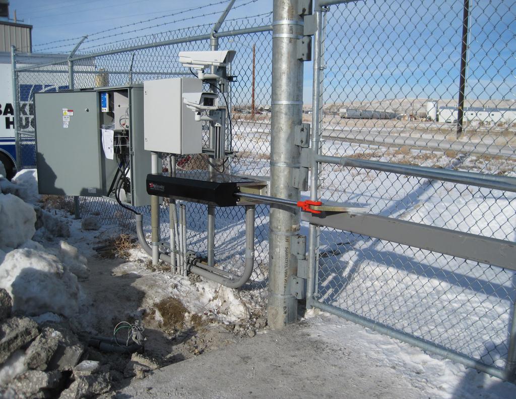
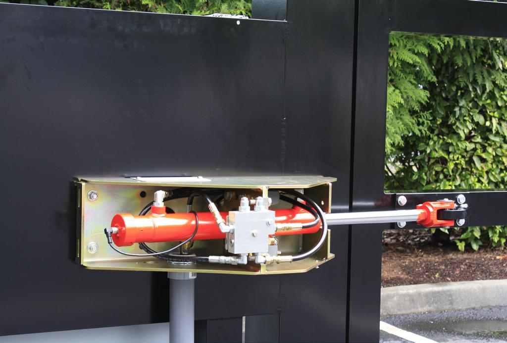
3 Assembly: Exploded Views 1a Two hoses connect to QDs (quick disconnects) on the hoses fed through conduit from the HydraSupply 1. Assemble and secure chassis to mounting surface.* 2. Feed hoses through conduit and connect them to the QD fittings (quick disconnects). 3. Ground the gate operator. 4 4-pin sensor wire connector mount** 27 (69 cm) 4. Feed sensor wire through conduit to HydraSupply and connect it to the 4-pin receiver board. *NOTE: Refer to Arm Geometry, on pages 3 and 4, for mounting dimensions and requirements NOTE: Anchor bolts for 40 and 40F. 1/2-inch, Grade 8. Minimum 4 bolts required for steel to steel mount. Anchoring to concrete is dependent on concrete strength. Before installing, consult a structural engineer. 13 (33 cm) Access cover plate (for conduit and hoses) HydraSwing 40 & 40F Right handing Brake valve location 3 Earth ground 2 HydraSwing: Model 40 and 40F HydraSwing 40 & 40F chassis dimensions: 27 L x 13 W (69 x 33 cm) HydraSwing 40 & 40F Left handing **NOTE: Depending on whether the chassis is mounted recessed or elevated, you will need to modify the gate mount to accommodate the gate geometry. 1b Base extension (option) 4 (10 cm) 20½ (52 cm) Additional 4 for the optional base extension Brake valve location Remove 2 phillips-head screws to move brake manifold and provide access to mounting holes on the HydraSwing chassis. 1c Conduit Ground rod Optional base extension provides 4 offset for 80F or 150 models. 41 (104 cm) Remove 5 fasteners on the top panel to access interior of HydraSwing. Tamper proof screws require TX40 drive bit (included). Move the brake manifold to mount the HydraSwing chassis whether you use the optional base extension or not. Base extension (option) NOTE: Outswing gate mount requires customer fabrication. See pages 4 and 5. NOTE: Anchor bolts for 80F and /8-inch, Grade 8. Minimum 4 bolts required for steel to steel mount. Anchoring to concrete is dependent on concrete strength. Before installing, consult a structural engineer. Nuts and washers (6x) secure optional base extension. HydraSwing 80F & 150 chassis dimensions: 41 L x 20½ W (104 x 52 cm) optional base extension adds an additional 4 inches to the width HydraSwing Installation and Assembly MX Rev. E Page 3
4 Determine Arm Geometry: 40 & 40F 1 Close the gate. Measurements are based on a closed gate. Use the hand pump, if necessary. For bi-parting (dual) gates and proper sequencing on HydraSwing 40 Twin or 40F Twin models, the hydraulic cylinder must be fully extended. Abiding by arm geometry on this page is critical. Inswing Closed Position: Center hinge Hinge centerline 34½ (88 cm) minimum 2 Three cylinder positions adjust for the differences in surface mounting requirements: shimmed, flush, or inset (notched). For example, inset type mounts use Cylinder Position 3. Mounting Surface: Shimmed, Flush, or Inset If Yf dimension is between Then use Cylinder Position 2¾ to 3¾ (7 to 9.5 cm) 1 Outswing Open Position: Center hinge Entering vehicle Shadow Loop 90 Opening Access control Photo eye 95 Opening 100 Opening mount 13 (33 cm) 1 to 2 (2.5 to 5 cm) 2 0 ± ½ (0 ± 1.3 cm) 3 Cut out view Conduit cover (2x) swing OPEN Open Position = E Extended in the Installer Menu swing OPEN Cylinder Position 3 Flush mount or slightly inset Hinge centerline Yf Outswing See NOTE s. Cylinder rod Roadway edge Inline hinge example Mounting surface NOTE: Outswing gate mount requires customer fabrication. 90 Opening C / L Open Position = R Retracted in the Installer Menu 95 Opening Opening and Geometry: Inswing Degree of Swing (13cm) Hinge centerline 100 Opening 8 (20 cm) 8¼ (21 cm) 8⅝ (22 cm) 14 (35cm) 8¼ (21 cm) 8 (20 cm) 7¾ (19.7 cm) 24 (61cm) 5 (13cm) 5¼ (13.3 cm) 5 (12.7 cm) 4¾ (12 cm) Dashed lines: Indicate mounting hole centerlines Yf Position 3 hinge centerline Mounting Surface NOTE: Use the Mounting Surface chart to determine the best position for the cylinder. Round up and shim to meet Yf dimension requirements. Cylinder Position 1 Cylinder Position 2 NOTE: Outswing gate mount requires customer fabrication. Cylinder rod Photo eye Opening and Geometry: Outswing Degree of Swing HydraSupply 90 8 (20 cm) 5¼ (13.3 cm) 8½ (21.6 cm) 95 8¼ (21 cm) 5⅝ (14.3 cm) 7½ (19 cm) 100 8⅝ (22 cm) 6 (15.2 cm) 6¾ (17.1 cm) Overhead View: Model 40 and 40F Cylinder Position 3 Mounting holes shared with Inswing mount shown: Center hinge brake cylinder bracket HydraSwing Installation and Assembly MX Rev. E Page 4 Discard washers and lock nuts if using Cylinder Position 3 Brake manifold Torque fasteners to 70 ft-lbs Cut or shim along mounting edge depending on your gate arm geometry. Refer to tables for and measurements. mount: 6½ inch dimension Cylinder end head with swivel Use the measurements for your gate type: Inswing or Outswing. Measure and cut (or shim) gate mount to meet the requirement. Fasten the gate mount to the cylinder to meet the requirement. Tack weld until hoses available or the accuracy of the dimensions are confirmed. The gate mount and cylinder need to remain in a horizontal plane throughout gate travel. If any vertical movement occurs, the load on the cylinder is strained and will lessen its life and void the Warranty.
5 Determine Arm Geometry: 80F & 150 hinge 13 (33 cm) 16 inches (40.6 cm) Optional base extension: Provides 4-inch offset from mounting surface. Anchor bolts: 5/8-inch, Grade 8 See NOTE on page 3. 2 (5 cm) 10 (25 cm) 1½ (3.8 cm) 3 (7.6 cm) Outswing gate mount requires customer fabrication Yf View B hinge Mounting bolts Centerlines NOTE: Use the chart below to determine Yf dimension requirements. If needed, notch or shim the mounting surface to remain within ± ¼ inch of the dimension given. hinge centerline Yf 5 (12.7 cm) 10 (25.4 cm) 20 (50.8 cm) Suggested minimum height from grade: 12 (30.5 cm) Optional base extension shown Overhead View Mounting Surface Mounting tab included: 1 (2.5 cm) thick Must be cut and welded by installer to meet measurement requirements. Mounting Dimension 90 Opening with Optional Base Extension: Provides 4-inch offset Hinge centerline 22¼ (57 cm) 1 Optional base extension: Provides 4-inch offset from mounting surface To assemble the HydraSwing 80F or 150, close the gate. Take measurements based on a closed gate position. 2 Determine the best geometry for your site. An optional 4-inch base extension may be ordered to help create the appropriate Yf mounting surface dimension. The gate mount and cylinder need to remain in a horizontal plane throughout gate travel. If any vertical movement occurs, the load on the cylinder is strained and will lessen its life and void the Warranty. mount Opening and Geometry: 80F & 150 Degree of Swing Yf ± ¼ (28 cm) 13½ (34.3 cm) 5 (12.7 cm) 9½ (24.1 cm) ¼ (28.6 cm) 13¼ (33.6 cm) 3½ (8.9 cm) 8 (20.3 cm) 7½ inch (19 cm) Models: 80F and 150 Fully extended cylinder: 62½ inches (159 cm) Minimum space required: 49 inches (125 cm) (Cylinder housing plus dimension) Minimum 41 inches (104 cm) Geometry: View B Outswing: 80F & 150 Degree of Swing Yf ± ¼ (30.5 cm) 11 (28 cm) 5 (12.7 cm) 13½ (34.3 cm) HydraSwing Installation and Assembly MX Rev. E Page 5
6 RPM A B STATUS OPEN +24V +24V EDGE Wiring AC Power DANGER Turn OFF AC power at the source (circuit breaker panel) before accessing the wires in the HydraSwing. Follow facility Lock Out/Tag Out procedures. Make sure all power switches are in the OFF position. Follow all electrical code standards and regulations. Power connection Size the primary wires, appropriately. Consider the voltage, horsepower, and length of the wire run from the main power panel. Verify you have the proper input voltage and make sure the motor and transformer are wired correctly. NOTE: Use a 20A (minimum) protected with a 20A Inverse Time Breaker for all AC motor connections. 1. Connect to Power: Three pig tails and a ground are available for connection to a 3 Phase power source (3Ø) on the back of the keypad display enclosure DRIVE POWER RS485 STOP BUTTON OPEN BUTTON CLOSE BUTTON REMOTE OPEN AND RADIO CONTROL OPEN/CLOSE OPEN PARTIAL INTERLOCK OPEN TIME CLOCK OPEN FREE EXIT DETECTOR DISABLE EXIT DETECTOR DISABLE CLOSE TIMER INSIDE OBSTRUCTION OUTSIDE OBSTRUCTION SHADOW/RESET EDGE SENSOR PHOTO EYE POWER 24 VOLTS MON PHOTO EYE POWER PHOTO EYE 17 OPEN DIRECTION 18 PHOTO EYE 19 CLOSE DIRECTION 20 CHARGER 21 AC LOSS HySecurity 22 LOCK INTERLOCK MX VERSION 23 EMERG CLOSE S/N 24 FIRE DEPT OPEN LED Smart Touch Controller LIMIT DUAL GATE RADIO OPTIONS 2. Connect AC Power: Wire nut the incoming power wires to their appropriate pig tails. Attach the ground wire to the chassis. A wiring diagram is provided in the appendix. Note that for 1Ø wiring, only the two outside connections/pig tails are used. Wiring of gate operators must conform to NFPA and NEC standards and comply with all local codes. When the installation is compliant and complete, turn on AC power at the source and at the control box. For Variable Frequency (VF) operators, make sure the connection wires match the voltage found on the operator s nameplate. WARNING In-Field Connections: HydraSwing operators are field re-configurable for 1Ø or 3Ø, 208/230VAC input power without changing the VFD. However, if reconfiguring from 208/230VAC to 460/480VAC the VFD Motor Controller in a 208/230VAC unit must be replaced with a VFD Motor Controller manufactured for the higher (460/480VAC) voltage input. Any electrical damage occurring to the operator will not be covered by the Warranty. VFD not shown USER 3 DISPLAY RS232 NO MOTOR USER 1 USER 2 FREE EXIT INSIDE OBSTR OUTSIDE OBSTR SHADOW RESET STOP/BUZZER WIEGAND Turning the Power Switch ON The AC power disconnect switch (ON/OFF switch) is located on the same enclosure as the STC keypad and display. When power is turned ON, a green status light on the Smart Touch Controller blinks. The status light appears below the disc battery and indicates that the processor is receiving power. Site Considerations HySecurity gate operators are intended for permanent installation. Make sure you prepare the site with the following considerations: Make sure all electrical wiring is properly routed via conduits. Check the distance of the wire run from the main panel to the gate operator. Make sure the wire size of the branch circuit supplying power to the gate operator is large enough to avoid excess voltage drop. Refer to Wire Sizing and Runs in the HydraSwing Programming and Operations Manual. Make sure the available power source matches the electrical requirements specified on the voltage nameplate. Green LED flashes indicating processor is receiving power. PHOTO EYE OPEN DIRECTION PHOTO EYE CLOSE DIRECTION Each gate operator is built to run on a specific line power voltage and phase. Failure to ensure the source voltage, phase and frequency match, what is specified for the equipment, may result is severe damage to the equipment. Make sure a 20A circuit (minimum) protected with a 20A Inverse Time Breaker is provided. Verify that the operator is electrically grounded per NFPA 780 and NEC Article 250, and local codes. NOTE: Refer to the HydraSwing Programming and Operations manual for Important Safety Instructions, programming, troubleshooting, maintenance and general information CHARGER AC LOSS LOCK INTERLOCK EMERG CLOSE FIRE DEPT OPEN HySecurity MX VERSION S/N LED Smart Touch Controller LIMIT DUAL GATE RADIO OPTIONS RPM A B OPEN +24V +24V DISPLAY EDGE STATUS RS232 SHADOW RESET WIEGAND WARNING HydraSwing operators CANNOT be connected to 115/120VAC, 1Ø power or 575V, 3Ø power. If any attempts are made to do so, serious injury and possible electrical shock may result. Any electrical damage occurring to the operator will not be covered by the Warranty HydraSwing Installation and Assembly MX Rev. E Page 6
7 Complete the Installation Replace Vent Plug with Breather Cap Manual Hand Pump: 40, 40F, 80F and 150 Models Vent plug DANGER Breather cap Failure to perform the following procedure will cause premature pump shaft failure and void the Warranty. When the hoses are installed, a hand pump can be used to manually operate the hydraulic mechanism that secures the gate. In the event of a power failure, manual operation is achieved by accessing the hydraulics cabinet. Follow the steps below to open or close the gate: NOTE: An integrated manual release mechanism exists on the brake manifold assembly. Open the using the Hand Pump The gate operator has a vent plug that keeps the hydraulic fluid from spilling during shipment. The vent plug must be replaced by the breather cap before operating the swing gate. Remove the vent plug and discard it. Replace the vent plug with the breather cap. 1. Open the HydraSupply cabinet. 2. Turn the power switch OFF. 3. Locate the hand pump and the Knurled Knob on the Open Valve. 4. Firmly, pull and twist the knurled knob counterclockwise. Release the knob so that it remains in the open position. Knurled knob NOTE: If the valve re-seats itself, repeat the pull and twist in the opposite direction until the valve remains open. 5. Begin pumping the handle up and down. As hydraulic fluid is pumped into the cylinder, it begins to move the gate Continue pumping until the gate reaches full open position. 7. Turn the knurled knob so it springs back to the closed position. Close the using the Hand Pump 1. Check that the knurled knob is in the closed position. Begin pumping the handle up and down. The gate slowly closes with the pumping motion. Manual Release 2. The gate will maintain its position whenever you stop pumping. 3. Continue pumping until the gate reaches the full closed position. WARNING Before attempting a manual release, make sure the gate is not in motion and power is disconnected (turned OFF). Cylinder pin The Manual Release is used to manually OPEN the gate for emergency access. To manually OPEN and CLOSE the gate during installation or power failure, use the Manual Hand Pump. When the hoses are installed, the gate may be opened (cylinder retracted) manually by moving the release lever as shown in the illustration. NOTE: For models 80F and 150, DO NOT extend the cylinder using the manual release lever. Refer to below. Outswing installation sites must pull the cylinder pin (disengages the gate from the operator) or use the hand pump. Integrated manual release Run mode Released position Pushing the gate closed when the lever is in the released position may cause an air pocket to form in the hydraulic cylinder and cause overflow from the reservoir. If you notice fluid leakage, stop gate travel immediately and use the hand pump. Released Brake manifold Run mode High capacity hand pump: 80F & 150 models Hand pump: 40 & 40F models HydraSwing Installation and Assembly MX Rev. E Page 7


8 MX
Unpack. Left Handing (L) the Operator. StrongArmPark DC Breakaway Bracket Installation Video
 the Operator. StrongArmPark DC Breakaway Bracket Installation Video") DC Left Handing (L) Standard. Factory ships left handing operator. NOTE: If your site requires right handing, place the order with your distributor as a StrongArmPark DC with right handing. Handing changes
DC Left Handing (L) Standard. Factory ships left handing operator. NOTE: If your site requires right handing, place the order with your distributor as a StrongArmPark DC with right handing. Handing changes
Part Diagrams. HydraSwing 40/40F Actuator. Part Name Part Number HydraSwing Models (current) Mount, Gate. Valve, Brake. Pin, Cylinder.
 Mount, Gate. Valve, Brake. Pin, Cylinder.") HydraSwing 40/40F Actuator Mount, Gate Valve, Brake Pin, Cylinder Hose Kit Brake Manifold Bearing, Tapped Cylinder Kit (Primary or Secondary) Cylinder Kit Cover, Chassis Part Name Part Number HydraSwing
HydraSwing 40/40F Actuator Mount, Gate Valve, Brake Pin, Cylinder Hose Kit Brake Manifold Bearing, Tapped Cylinder Kit (Primary or Secondary) Cylinder Kit Cover, Chassis Part Name Part Number HydraSwing
Quick Start Guide SlideSmart DC HD25, HD30
 Quick Start Guide SlideSmart DC HD25, HD30 Pad or post-mount electromechanical slide gate operator with Smart DC Controller 800-321-9947 253-867-3700 www.hysecurity.com Industrial Commercial Crash Parking
MODEL D-SBG Single Arm Barrier Gate Operator
 INSTALLATION AND OWNER S MANUAL MODEL D-SBG Single Arm Barrier Gate Operator UL 325 and UL 991 Listed WITH NITRO BOARD (SEE SUPPLEMENTAL MANUAL) Serial #: Date Installed: Your Dealer: READ THIS MANUAL
JEEVES. JEEVES Installation Manual. Installation Manual The Easiest Do-It-Yourself Dumbwaiter on the Market
 1 888-323-8755 www.nwlifts.com JEEVES Installation Manual The Easiest Do-It-Yourself Dumbwaiter on the Market This manual will cover the installation procedure step-by-step. The installation of this dumbwaiter
WedgeSmart. Installation Instructions. Surface mount parking wedge with electromechanical barrier arm operator and Smart DC Controller
 WedgeSmart DC TM Installation Instructions Models WedgeSmart DC WedgeSmart DCS (Solar) Surface mount parking wedge with electromechanical barrier arm operator and Smart DC Controller MX3762-01 WedgeSmart
PowerMaster MODEL MBG. Installation Manual U L R UL 325 AND UL 991 LISTED MEDIUM DUTY BARRIER GATE OPERATOR TABLE OF CONTENTS
 PowerMaster TABLE OF CONTENTS MODEL MBG MEDIUM DUTY BARRIER GATE OPERATOR Important Safety Information...... 3 System Designer Safety Instructions.......4 Installer Safety Instructions....... 5 Installation
Alliance Towel Dispensing System. Operation Manual
 Alliance Towel Dispensing System Operation Manual Alliance Towel Dispensing System Table of Contents Safety Information... page 2 Mounting Instructions... page 3 Towel Loading Instructions... page 7 Settings...
APOLLO Gate Operators, Inc.
 APOLLO Gate Operators, Inc. Model BA12 12 VOLT DC BARRIER ARM OPERATOR INSTALLATION MANUAL 0707 CONTENTS IMPORTANT SAFETY INSTRUCTIONS... 3 Applications... 4 Pre-Installation Checklist... 5 Operator Installation...
MODEL D-WBG Wishbone Arm Barrier Gate Operator
 INSTALLATION AND OWNER S MANUAL MODEL D-WBG Wishbone Arm Barrier Gate Operator UL 325 and UL 991 Listed WITH NITRO BOARD (SEE SUPPLEMENTAL MANUAL) Serial #: Date Installed: Your Dealer: READ THIS MANUAL
MODEL JH JACKSHAFT INDUSTRIAL DOOR OPERATOR INSTALLATION MANUAL. OPERATOR SPECIALTY COMPANY, INC. P.O. Box 128 Casnovia, MI 49318
 MODEL JH JACKSHAFT INDUSTRIAL DOOR OPERATOR INSTALLATION MANUAL OPERATOR SPECIALTY COMPANY, INC. P.O. Box 128 Casnovia, MI 49318 OSCO requires the use of a reversing edge or photoelectric control for pedestrian
APOLLO Gate Operators, Inc.
 APOLLO Gate Operators, Inc. Model 3500ETL/3600ETL Commercial Swing Gate Operator INSTALLATION MANUAL 01/08 CONTENTS IMPORTANT SAFETY INSTRUCTIONS. 3 Applications... 4 Pre-Installation Checklist... 5 Parts
HYPPOETL HYPPO DUALETL 12 VOLT DC Swing Gate Operator
 HYPPOETL HYPPO DUALETL 12 VOLT DC Swing Gate Operator Manufactured by NICE SpA INSTALLATION MANUAL 08/10 CONTENTS IMPORTANT SAFETY INSTRUCTIONS... 3 Applications...... 4 Pre-Installation Checklist... 5
INSTALLATION INSTRUCTIONS AND OPERATION MANUAL
 INSTALLATION INSTRUCTIONS AND OPERATION MANUAL UL325-2010 Compliant Commercial and Industrial Door Operator Logic Control Continuous Duty IMPORTANT INSTALLATION INSTRUCTIONS WARNING To reduce the risk
Premium Security and Reliability
 Premium Security and Reliability a company of TheNiceGroup The Premium Slide Gate Operator The ultimate in quality and reliability Decades long life and low maintenance Move the longest, heaviest gates
Technical Installation and Service Manual
 1. 2. 7 3. 4. Technical Installation And Service Manual RS-500 Door with Brother Operator RollSeal 1733 County Road 68 Bremen, Alabama 35033 256-287-7000 Part No 4801-5159 Rev 11-2015 Technical Installation
INSTALLATION INSTRUCTIONS AND OPERATION MANUAL
 INSTALLATION INSTRUCTIONS AND OPERATION MANUAL FS Series Rolling Fire Door Operators UL325-2010 Compliant Restricted Duty Operators CORPORATION IMPORTANT INSTALLATION INSTRUCTIONS WARNING To reduce the
Installation Instructions Capacity 10,000 lbs. (100 Series Lift)
") Installation Instructions Capacity 10,000 lbs. (100 Series Lift) IMPORTANT Reference ANSI/ALI ALIS, Safety Requirements for Installation and Service of Automotive Lifts before installing lift. OPERATING
Installation Instructions Capacity 10,000 lbs. (100 Series Lift) IMPORTANT Reference ANSI/ALI ALIS, Safety Requirements for Installation and Service of Automotive Lifts before installing lift. OPERATING
SECTION HYDRAULIC FOUR FOLD DOORS MODEL 48 LOUVERS
 SECTION 08350 HYDRAULIC FOUR FOLD DOORS MODEL 48 LOUVERS PART 1 GENERAL 1.01 RELATED DOCUMENTS A. Drawings and general provisions of the Contract, including General and Supplementary Conditions and Division-1
Instruction Manual for the. E-SL 450 Series
 Instruction Manual for the E-SL 450 Series Estate Slide Summary of Functions The Estate Slide is only to be used for vehicular Slide gates in a Class I setting. Class I: A vehicular gate opener (or system)
Vehicular Swing Gate Operator. Nice. Titan 912L. The Titan 912L Gate Operator is intended for use with vehicular swing
 Vehicular Swing Gate Operator Nice Gate Operators Titan 912L The Titan 912L Gate Operator is intended for use with vehicular swing gates. The Titan 912L Gate Operator can be used in Class I, Class II and
GENERAL SAFETY... 3 PARTS LIST...
 Rev 17a 1 GENERAL SAFETY... 3 PARTS LIST... 4 GTR100... 4 GTR058... 5 TECHNICAL SPECIFICATIONS... 6 FEATURES:... 6 QUICK INSTALLATION GUIDE... 7 GATE ARM INSTALLATION... 8 BEFORE YOU START... 8 INSTALLATION
Technical Installation and Service Manual RollSeal 1733 County Road 68 Bremen, Alabama 35033
 Technical Installation and Service Manual RollSeal 1733 County Road 68 Bremen, Alabama 35033 4801-5159 rev. 05/14 Technical Installation and Service Manual Page 1 of 26 1. Ratings and Specifications Motor
VEHICULAR AC & DC. Residential Apartment/College Residence Halls Gated Communities Mixed Use Buildings Commercial/Industrial Parking Self Storage
 VEHICULAR AC & DC SWING GATE OPERATORS Residential Apartment/College Residence Halls Gated Communities Mixed Use Buildings Commercial/Industrial Parking Self Storage AC & DC POWERED Gate OPERATORS Safety
Continuing Education Course #206 Introduction to Designing Machine Control Systems Part 2
 1 of 5 Continuing Education Course #206 Introduction to Designing Machine Control Systems Part 2 1. Continuing to answer the following questions indicates that you understands that the presented material
Opening Quality Doors Around The World. Installation Instructions Bi-Parting Freight Doors - Q Style (Power and Manual)
") Opening Quality Doors Around The World www.couriondoors.com Installation Instructions Bi-Parting Freight Doors - Q Style (Power and Manual) Table of Contents For Immediate Help Call 1-800-533-5760 Q Style
Opening Quality Doors Around The World www.couriondoors.com Installation Instructions Bi-Parting Freight Doors - Q Style (Power and Manual) Table of Contents For Immediate Help Call 1-800-533-5760 Q Style
INSTALLATION INSTRUCTIONS AND OPERATION MANUAL
 INSTALLATION INSTRUCTIONS AND OPERATION MANUAL NEMA 4X UL325-2010 Compliant Commercial and Industrial Door Operator Logic Control Continuous Duty IMPORTANT INSTALLATION INSTRUCTIONS WARNING To reduce the
Order Form SwingRiser Twin (HRG 222) Gate Operator
 Gate Operator") Order Form SwingRiser Twin (HRG 222) Gate Operator Two posts operating two gate panels from one controller NOTE: If two gate panels or any part of the gate panels overlap each other when closed, each post
Order Form SwingRiser Twin (HRG 222) Gate Operator Two posts operating two gate panels from one controller NOTE: If two gate panels or any part of the gate panels overlap each other when closed, each post
PLASTIC FOLDING ARM KIT This kit is designed for the 1600 model barrier gate operators only. Recommended for low headroom applications.
 PLASTIC FOLDING ARM KIT This kit is designed for the 600 model barrier gate operators only. Recommended for low headroom applications. Kit Includes: Plastic Arms Attachment Assembly Clamp Locking Turnbuckle
A B C D E F. b.tools Required (supplied by others) 3/16" Drill Bit 3/8" Wrench Phillips Head Screwdriver
 3/16 Drill Bit 3/8 Wrench Phillips Head Screwdriver") Page 1 of 13 5E.1 Parts List a. Below Deck Automatic Retractable Security Cover Kit (1) Tube End Bearing Plate (A) (1) Rope Reel with Motor Attached (B) (1) Rope Reel Cover (C) (1) Cover Drum (1) Cover
Page 1 of 13 5E.1 Parts List a. Below Deck Automatic Retractable Security Cover Kit (1) Tube End Bearing Plate (A) (1) Rope Reel with Motor Attached (B) (1) Rope Reel Cover (C) (1) Cover Drum (1) Cover
INSTALLATION MANUAL MODEL SL 1000-X3 HEAVY DUTY, HIGH CYCLE SLIDE GATE OPERATOR
 ESTATE SERIES X3 INSTALLATION MANUAL MODEL SL 1000-X3 HEAVY DUTY, HIGH CYCLE SLIDE GATE OPERATOR MODEL SL 1000-X3 IS FOR VEHICULAR PASSAGE GATES ONLY, NOT INTENDED FOR PEDESTRIAN PASSAGE GATE USE 3 YEAR
ASSA ABLOY Series Power Operator Installation and Instruction ASSA Manual ABLOY ASSA ABLOY
 00 Series Power Operator Installation and Instruction ASSA Manual ABLOY Item No. Description Motor (00M) Cover (00COV) Control Inverter (00IN) Power Supply VDC (00PS) Track Assembly (0-) / Replacement
January 2018 PRICE SCHEDULE A 2.0 Vehicular Traffic Control
 Section A1 This Price Schedule is effective January 1, 2018. Date Page Comment 1-1-18 All January, 2018 Price Schedule update. 1-26-18 6, 7 Added 1601-180, 1601-181 Gray Housing and 1601-283 Gray arm hub
INSTALLATION INSTRUCTIONS AND OPERATION MANUAL
 INSTALLATION INSTRUCTIONS AND OPERATION MANUAL Commercial and Industrial Fire Door Operator Logic Control Restricted Duty Fire Door Operators IMPORTANT INSTALLATION INSTRUCTIONS WARNING To reduce the risk
6002 swing gate actuator - installation guide
 600 swing gate actuator - installation guide 600 Residential Swing Gate Actuator Installation Guide DKS DoorKing, Inc. 0 Glasgow, Avenue Inglewood, Ca. 900 0.645.00 0.64.586 fax info@doorking.com www.doorking.com
PN: 6410T0022 Rev. 8/18/2014 Revision D Albany RR300 Stainless Mechanical Install & Owner s Manual
 PN: 6410T0022 Rev. 8/18/2014 Revision D Albany RR300 Stainless Mechanical Install & Owner s Manual ASSA ABLOY ENTRANCE SYSTEM. All Rights Reserved 975-A Old Norcross Road, Lawrenceville, Georgia 30046
INSTALLATION INSTRUCTIONS AND OPERATION MANUAL
 INSTALLATION INSTRUCTIONS AND OPERATION MANUAL - 1/3, 1/2, 3/4hp UL325-2010 Compliant Commercial and Industrial Door Operator Logic Control Duty Cycle 20 Cycles per Hour IMPORTANT INSTALLATION INSTRUCTIONS
Gen INSTALLATION MANUAL
 Gen 2 INSTALLATION MANUAL READ THIS FIRST Installation of this system should be carried out by qualified persons familiar with the general installation of law enforcement electronics commonly installed
Linear Actuator Swing Gate Operator Installation Manual Model # LA405-24
 Linear Actuator Swing Gate Operator Installation Manual Model # LA405-24 2 Contents Contents Product Information and Specs. 3 Mechanical 3 Electrical, Line Connections 3 Electrical, Control Connections
January 2018 PRICE SCHEDULE A 2.0 Vehicular Traffic Control
 Section A1 This Price Schedule is effective January 1, 2018. Date Page Comment 1-1-18 All January, 2018 Price Schedule update. 1-26-18 6, 7 Added 1601-180, 1601-181 Gray Housing and 1601-283 Gray arm hub
Therm-L-Tec Building Systems LLC. Therm-L-Tech. Power Operated Retrofit Kit 230 VAC or 440/480 VAC 50/60 Hz Installation and Setup Manual
 Therm-L-Tec Building Systems LLC Therm-L-Tech Power Operated Retrofit Kit 230 VAC or 440/480 VAC 50/60 Hz Installation and Setup Manual Rev. A 01/2015 Index Index 1 Electrical Requirements for Therm-L-Tec
INSTALLATION INSTRUCTIONS AND OPERATION MANUAL
 INSTALLATION INSTRUCTIONS AND OPERATION MANUAL FS Series Rolling Fire Door Operators CORPORATION GENERAL NOTES TO REDUCE THE RISK OF SEVERE INJURY OR DEATH, READ AND FOLLOW ALL INSTALLATION INSTRUCTIONS
DC Series Installation Manual (# )
") DC Series Installation Manual (# 101630) Page 1 of 33 In this booklet you will find: TOWER INSTALLATION... 3 U-Bolt Style mount... 4 Side Frame Style mount... 4 PIVOT INSTALLATION... 5 External Pivot Installation:
DC Series Installation Manual (# 101630) Page 1 of 33 In this booklet you will find: TOWER INSTALLATION... 3 U-Bolt Style mount... 4 Side Frame Style mount... 4 PIVOT INSTALLATION... 5 External Pivot Installation:
MODEL WBG WISHBONE BARRIER GATE OPERATOR
 TABLE OF CONTENTS MODEL WBG WISHBONE BARRIER GATE OPERATOR Important Safety Information.....3 System Designer Safety Instructions.......4 Installer Safety Instructions........ 5 End User Safety Warnings...-
Power Operated Retrofit Kit for Manual Door 230 VAC or 440/480 VAC 50/60 Hz Installation and Setup Manual
 Therm-L-Tec Building Systems LLC Therm-L-Tech Power Operated Retrofit Kit for Manual Door 230 VAC or 440/480 VAC 50/60 Hz Installation and Setup Manual Rev. A 10/2014 Index Index 1 Electrical Requirements
January 2018 PRICE SCHEDULE A 2.0 Vehicular Traffic Control
 Section A1 This Price Schedule is effective January 1, 2018. Date Page Comment 1-1-18 All January, 2018 Price Schedule update. 1-26-18 6, 7 Added 1601-180, 1601-181 Gray Housing and 1601-283 Gray arm hub
Inteli-Lift GEN II DUMBWAITER
 1 877-345-4387 530-295-4900 www.eilifts.com Inteli-Lift GEN II DUMBWAITER The Easiest Dumbwaiter system on the Market Fully UL Certified Dumbwaiter Systems UL File # SA32120 This manual will cover the
TITAN Motor Truck Scale
 S C A L E S Instruction Manual TITAN Motor Truck Scale Model: 00 Series FAIRBANKS 00 by Fairbanks Scales Inc. All rights reserved 0 Revision # 0/0 Amendment Record Titan 00 Series Motor Truck Scale 0 Manufactured
Requirements LEO Power Operator Installation Instructions Patents: 5,881,497; 7,316,096; 7,484,333 CAUTION CAUTION WARNING
 CAUTION 80-957-00-00 (08-0) Series 570 Openings 85 to 0 or to 70 Double Lever Arm Application for Frame Reveals (76) to 7 (78mm)* Stop (Push) Side of Installation 5700 LEO Operator Installation Instructions
Section A1. Vehicular Traffic Control. This Price Schedule is effective January 7, Date Page Comment
 January 2019 PRICE SCHEDULE A 2.0 Section A1 This Price Schedule is effective January 7, 2019. Date Page Comment 1-2-19 All January, 2019 Price Schedule update. Specifications subject to change without
#366. Gate Operator Pre-Installation and Site Planning. Introduction
 Gate Operator Pre-Installation and Site Planning Introduction Although each manufacturer s equipment has unique design characteristics and functions, gate operators are somewhat similar in many installation
A B C D E F. Tools Required (supplied by others)
") Page 1 of 17 Parts List Below Deck Automatic Retractable Security Cover Kit (1) Tube End Bearing Plate (A) (1) Rope Reel and Cover Drum Motor Assembly (B) (1) Cover Drum (1) Pulley Support Channel (2)
Page 1 of 17 Parts List Below Deck Automatic Retractable Security Cover Kit (1) Tube End Bearing Plate (A) (1) Rope Reel and Cover Drum Motor Assembly (B) (1) Cover Drum (1) Pulley Support Channel (2)
2904 Power Supply Installation Instructions I-EA00041
 FEATURES Controls an opening with electrified locking device and automatic door operator Separate inputs for activation switch on entry and exit sides of opening Separate 24 VDC outputs for fail safe and
Property of American Airlines
 Section 2: Operation 1. GENERAL INFORMATION Safety First! is the motto at Tesco; therefore, the first part of the Operation section begins with safety features and procedures. Operation of the Tesco CL80-20
GATES-ELECTRIC AND MECHANICAL SELF CLOSING 2000 SERIES
 2014 GATES-ELECTRIC AND MECHANICAL SELF CLOSING TURNSTILE SECURITY SYSTEMS Inc. THIS CATALOGUE IS MEANT AS REFERENCE MATERIAL FOR TURNSTILE SECURITY SYSTEMS Inc. FOR THE SOLE PURPOSE OF INFORMING POTENTIAL
ASSA ABLOY Series Power Operator Installation and Instruction ASSA Manual ABLOY ASSA ABLOY
 0 Series Power Operator Installation and Instruction ASSA Manual ABLOY Item No. Description Motor (00M) Cover (00COV) Control Inverter (00IN) Power Supply VDC (00PS) / Replacement Motor Key (00KEY) Rod
Apartment Complex/Gated Communities Mixed Use Buildings Commercial/Industrial Parking Self Storage Maximum Security
 Apartment Complex/Gated Communities Mixed Use Buildings Commercial/Industrial Parking Self Storage Maximum Security PARKING CONTROL A System for All Applications Barrier Arm Options Aluminum and wood arms
Gate Operators, Inc. Model 7100UL Residential & Medium Duty Commercial Slide Gate Operator INSTALLATION MANUAL
 Gate Operators, Inc. Model 7100UL Residential & Medium Duty Commercial Slide Gate Operator INSTALLATION MANUAL 10-04-00 CONTENTS Safety Precautions... 2 Applications... 3 Pre-Installation Checklist...
INSTALLATION AND OPERATING INSTRUCTIONS For Model GL1 Gate Locks
 Securitron Magnalock Corp. Tel 775.355.5625 550 Vista Boulevard Fax 775.355.5633 Sparks, NV 89434 info@securitron.com www.securitron.com ASSA ABLOY, the global leader in door opening solutions INSTALLATION
C FORD F250 / F L POWERSTROKE DIESEL WITH AUTOMATIC TRANSMISSIONS ONLY
 EXHAUST BRAKES C40019 1999-2003 FORD F250 / F350 7.3L POWERSTROKE DIESEL WITH AUTOMATIC TRANSMISSIONS ONLY Getting Started Thank you and congratulations on your purchase of a Pacbrake exhaust retarder.
Installation Instructions Pro Bandit Shifter Fits: GM Powerglide Automatic Transmissions
 Installation Instructions Pro Bandit Shifter Fits: 1962-1973 GM Powerglide Automatic Transmissions Part # 80793 WORK SAFELY! For maximum safety, perform this installation on a clean, level surface and
DUMP BODY SPREADERS INSTALLATION INSTRUCTIONS
 DUMP BODY SPREADERS INSTALLATION INSTRUCTIONS (Includes PS350 & PS400) EFFECTIVE 09/2011 Revision A 1330 76TH AVE SW CEDAR RAPIDS, IA 52404-7052 PHONE (319) 363-8281 FAX (319) 286-3350 www.highwayequipment.com
C40008 & C40009 EXHAUST BRAKES
 EXHAUST BRAKES C40008 & C40009 1995 2003 Ford F250 / F350 7.3 L Powerstroke Diesel with manual transmissions 1995 1998 Ford F250 / F350 7.3 L Powerstroke Diesel with automatic transmission* *Requires the
EXTREME R MOTOR OWNER'S MANUAL
 EXTREME R MOTOR OWNER'S MANUAL 2 HP, 3 HP & 5 HP WITH SELF-ENGAGING CHAIN HOIST FOR TECHNICAL SUPPORT PLEASE CALL 1-(855) 594-4969 3137B(0) ECN 1313 BY JM 7/9/15 OPERATOR SERIAL# PRO-FDG MOTOR OPERATORS
Parking Gate INSTALLATION AND OPERATION MANUAL
 AGP-1700 Series Parking Gate INSTALLATION AND OPERATION MANUAL Amano Cincinnati, Inc. reserves the right to make equipment changes and improvements which may not be reflected in this document. Portions
Installation/Owner s Manual
 CLASS MODEL SERIAL HP 53382 DoorKing, Inc., Inglewood, CA Installation/Owner s Manual Use this manual for circuit board 4502-010 Revision K or higher. For operators manufactured July 2011and later. Series
SUNROOF - SERVICE INFORMATION ADJUSTMENTS
 SUNROOF - SERVICE INFORMATION DESCRIPTION OPERATION DIAGNOSIS AND TESTING POWER TOP - SUNROOF SUNROOF ASSEMBLY-MODULE REMOVAL INSTALLATION CHANNEL-DRAIN REMOVAL INSTALLATION COVER-GUIDE MECHANISM REMOVAL
<THESE INSTRUCTIONS MUST BE GIVEN TO THE END USER> B&W
 B&W Trailer Hitches 6 Hawaii Rd / PO Box 86 Humboldt, KS 66748 P:60.473664 F:60.869.903 Turnoverball Gooseneck Hitch Installation Instructions MODEL 08
10 Commercial, Industrial, Agricultural Services
 10 Commercial, Industrial, Agricultural Services This section describes the Power Company requirements for commercial, industrial, and agricultural services. This section covers single phase and three
OPERATION AND MAINTENANCE MANUAL
 WREN IBT SERIES HYDRAULIC TORQUE WRENCHES IBT SQUARE DRIVE SERIES OPERATION AND MAINTENANCE MANUAL FOR WREN Products: POINT 75, 1IBT, 3IBT, 5IBT, 8IBT, 10IBT, 20IBT, 25IBT, 35IBT, 50IBT SQUARE DRIVE HYDRAULIC
PH3 AIR INTAKE EMERGENCY SHUT-OFF VALVE WITH POWERGUARD SMART OVERSPEED LIMITER. Generic PH3 Truck Shut-Off Valve Kit.
 PH3 AIR INTAKE EMERGENCY SHUT-OFF VALVE WITH POWERGUARD SMART OVERSPEED LIMITER Generic PH3 Truck Shut-Off Valve Kit www.powerhalt.com INSTALLATION REQUIREMENTS & RECOMMENDATIONS: Prior to the installation,
INSTALLATION INSTRUCTIONS AND OPERATION MANUAL
 INSTALLATION INSTRUCTIONS AND OPERATION MANUAL - 1/3, 1/2, 3/4hp UL325-2010 Compliant Commercial and Industrial Door Operator Logic Control Duty Cycle 20 Cycles per Hour IMPORTANT INSTALLATION INSTRUCTIONS
INSTALLING THE NEUTRAL SAFETY SWITCH WIRES
 Installation Instructions Magnum Grip Pro Bandit Shifter Part Number 81045 & 81046 2004, 2003 by B&M Racing and Performance Products (Visit www.bmracing.com for additional products and product information)
MODEL SW 2000-B1 SWING GATE OPERATOR (-68 BOARD)
") Doc 6001242 (01-20273) Rev C INSTALLATION AND OPERATION INSTRUCTIONS MODEL FOR THE MODEL SW 2000-B1 SWING GATE OPERATOR (-68 BOARD) TABLE OF CONTENTS SAFETY SUMMARY... 3 BASIC INSTALLATION HINTS AND RULES...
Doc 6001242 (01-20273) Rev C INSTALLATION AND OPERATION INSTRUCTIONS MODEL FOR THE MODEL SW 2000-B1 SWING GATE OPERATOR (-68 BOARD) TABLE OF CONTENTS SAFETY SUMMARY... 3 BASIC INSTALLATION HINTS AND RULES...
EAGLETRON II REMOTE CONTROL OPERATOR and MAINTENANCE. Remote Control Procedure
 EAGLETRON II REMOTE CONTROL OPERATOR and MAINTENANCE Remote Control Procedure WARNING! DO NOT OPERATE REMOTE CONTROL UNLESS YOU HAVE A CLEAR VIEW OF THE REAR OF THE TRAILER. WARNING! THE OPERATOR IS REQUIRED
CRITICAL DIMENSION CHART
 HINGE ASSEMBLY (SEE DETAIL #4) A = CLEAR OPENING WIDTH GATE FRAME LATCH ASSEMBLY (SEE DETAIL #3) HINGE POST (SIZE ACCORDING TO GATE LENGTH) 1 4" O.D. LATCH POST HINGE ASSEMBLY (SEE DETAIL #4) 3/16" S.S.
OEM Manual. 4042SA Leak Detecting Spill Alarm Instruction manual
 OEM Manual 4042SA Leak Detecting Spill Alarm Instruction manual 1 These instructions generally describe the installation, operation, and maintenance of, subject equipment. The manufacturer reserves the
SECTION LIFT ARM PARKING GATES
 St. Anthony of Padua Catholic Church Phase I The Woodlands, Texas JRA Proj. No. 15004 Issued for Bidding - 1/20/2016 SECTION 11 12 33.13 LIFT ARM PARKING GATES PART 1 - GENERAL 1.01 SUMMARY A. Section
Model 2300DL Installation Guide
 Model 2300DL Installation Guide POWER ACCESS CORPORATION 4 HERSHEY DRIVE, DOCK 4 ANSONIA, CT 06401 800-344-0088 WEBSITE: www.power-access.com EMAIL: salesinfo@power-access.com 1 STANDARD PARTS MODEL 2300DL
PowerLogic High Density Metering System 4-Meter Enclosure Installation Guide
 PowerLogic High Density Metering System 4-Meter Enclosure Installation Guide 7002-0289-00 Instruction Bulletin HAZARD CATEGORIES AND SPECIAL SYMBOLS Read these instructions carefully and look at the equipment
5600 Series Power Operator Installation and Instruction Manual
 5600 Series Power Operator Installation and Instruction Manual 80-956-000-00 (08-) 5 ASSA ABLOY 6 Item No. Description Motor (5600M) Cover (5600COV) Control Inverter (5600IN) Power Supply VDC (5600PS)
MODEL 6120 SERIES Hydraulic Pumping Unit (HPU) W/Logo
 W/Logo") MODEL 6120 SERIES Hydraulic Pumping Unit (HPU) W/Logo INSTALLATION MANUAL Corporate Office & Tech Support: 5900 S. Lake Forest Drive Suite 230 McKinney, TX 75070 Phone: (972) 385-7899 Toll Free: (800)
MODEL 6120 SERIES Hydraulic Pumping Unit (HPU) W/Logo INSTALLATION MANUAL Corporate Office & Tech Support: 5900 S. Lake Forest Drive Suite 230 McKinney, TX 75070 Phone: (972) 385-7899 Toll Free: (800)
Model 2300JL Installation Guide
 Model 2300JL Installation Guide POWER ACCESS CORPORATION 4 HERSHEY DRIVE, DOCK 4 ANSONIA, CT 06401 800-344-0088 WEBSITE: www.power-access.com EMAIL: salesinfo@power-access.com 1 STANDARD PARTS MODEL 2300JL
CONTROL FEATURES AVAILABLE OPTIONS
 Vari Speed A2000 TABLE OF CONTENTS Control Features Options Application Data Operating Condition s Control Ratings Chart Mounting Dimensions Installation and Wiring Typical Wiring Diagram Schematic (Block
INSTALLATION MANUAL. Melink Corporation (513) Revision
 Revision") INSTALLATION MANUAL Revision 130711 Table of Contents Step Installation Contractor Page 1 Install System Controller Electrical 4 2 Install Variable Frequency Drive Electrical 6 3 Install Touchpad Mechanical
INSTALLATION MANUAL Revision 130711 Table of Contents Step Installation Contractor Page 1 Install System Controller Electrical 4 2 Install Variable Frequency Drive Electrical 6 3 Install Touchpad Mechanical
INSTALLATION MANUAL MODEL SW 2000-X3 HEAVY DUTY, HIGH CYCLE SWING GATE OPERATOR
 E S T A T E S E R I E S X3 INSTALLATION MANUAL MODEL SW 2000-X3 HEAVY DUTY, HIGH CYCLE SWING GATE OPERATOR MODEL SW 2000-X3 IS FOR VEHICULAR PASSAGE GATES ONLY, NOT INTENDED FOR PEDESTRIAN PASSAGE GATE
poollux Power plx-pw60 & plx-pw100
 poollux Power plx-pw60 & plx-pw100 ETL LISTED Conforms to UL STD 379; Certifi.ed.to.CSA.STD.C22.2.#218.1 5005508 Installation Instructions Read all instructions before attempting to perform installation
Table of Contents. General Safety Preparation for Installation Parts List Optional Accessories Part List... 5
 REV 12a Table of Contents General Safety....... 2 Preparation for Installation....... 3 Parts List....... 4 Optional Accessories Part List...... 5 Technical Specifications & Feature...... 5 Installation
Installation Instructions For Motor Control Center (MCC) Units
 Units") s Page 1 of 8 Installation Instructions December, 2013 Installation Instructions For Motor Control Center (MCC) Units Hazardous voltage. Will cause death or serious injury. Always de-energize and ground
s Page 1 of 8 Installation Instructions December, 2013 Installation Instructions For Motor Control Center (MCC) Units Hazardous voltage. Will cause death or serious injury. Always de-energize and ground
VEHICULAR DC SWING GATE OPERATORS. Residential Light Industrial. Rev. 3/17
 VEHICULAR DC SWING GATE OPERATORS Rev. 3/17 Residential Light Industrial Swing Gate Power Options Residential - Light Commercial 115 Volt AC Power es DETAILS: Converts 115 VAC to 24 VDC operating voltage
650 Series Cargo Van Lift Mounting Instructions Fullsize Ford 1992-Present
 TOMMY GATE OWNER'S / OPERATOR'S MANUAL 650 Series 650 LB Capacity 650 Series Cargo Van Lift Mounting Instructions Fullsize Ford 1992-Present Installing the Base Plate 1. Examine the interior and exterior
Installation and Maintenance Manual
 Installation and Maintenance Manual Swing Gate Operator Model HL410-21 & HL410L-21 2 Contents Contents Parts & Components 3 Specifications & Capacities 4 Safety Information 6 Installer 6 End User 7 General
MODEL 611x SERIES Sliding Gate Barriers Hydraulic Pumping Unit (HPU)
") MODEL 611x SERIES Sliding Gate Barriers Hydraulic Pumping Unit (HPU) INSTALLATION MANUAL CORPORATE OFFICE: 5900 S. Lake Forest Drive Suite 230 McKinney, TX 75070 PHONE: 800-367-0387 FAX: (972) 385-9887
MODEL 611x SERIES Sliding Gate Barriers Hydraulic Pumping Unit (HPU) INSTALLATION MANUAL CORPORATE OFFICE: 5900 S. Lake Forest Drive Suite 230 McKinney, TX 75070 PHONE: 800-367-0387 FAX: (972) 385-9887
Installation/Owner s Manual
 53382 HP Read owner s manual and safety instructions. Installation/Owner s Manual Use this manual for circuit board 4502-010 Revision K or higher. For operators manufactured July 2011and later. Series
Installation Manual. For. High Speed Alumavator and Platinum. 10 and 23 Degree. Elevator Boat Lifts
 Installation Manual For High Speed Alumavator and Platinum 10 and 23 Degree Elevator Boat Lifts Page 2 Safety Precautions 1. Your boat lift is a heavy duty piece of equipment. It is important that all
Instruction Bulletin. Jockey Pump Controller
 Instruction Bulletin Jockey Pump Controller Installation Start Up Service This instruction bulletin is a guide for personnel involved with maintenance, engineering and approval of Fire Pump equipment and
Nanometrics Solar Power System
 Nanometrics Solar Power System Installation Guide Nanometrics Inc. Kanata, Ontario Canada 2003 Nanometrics Inc. All Rights Reserved. Installation Guide The information in this document has been carefully
Model 712 Cable Crash Beam Vehicle Barrier
 Installation and Operations Manual Model 712 Series Model 712 Cable Crash Beam Vehicle Barrier INSTALLATION MANUAL Corporate Office & Technical Support: 5900 S. Lake Forest Drive, Suite 230 McKinney, TX
Enclosure for AMP1 Series Energy Meters with Swing Panel Kit
 GE Industrial Solutions DET-809 Installation Instructions AMP1N4 Enclosure for AMP1 Series Energy Meters with Swing Panel Kit Safety FCC PART 15 INFORMATION NOTE: This equipment has been tested by the