- 2 - c) Gearbox: Gearcase modified, Pressure Regulator now fitted to LH side. Gearbox cover :- Oil filler now at front.
|
|
|
- Dennis Walters
- 5 years ago
- Views:
Transcription
1 Citroën DS Electronic Injection Course 1) Introduction:- -Why Injection? To supply to the engine the exact quantity of fuel it requires in all the different conditions of use. The beet carburettors can only do this at certain points in the load curve, properly designed injection equipment can do it practically all the time. Why electronic injection? Mechanical and electromechanical systems depend on moving rods and arms and levers, they therefore have a certain delay in their response time; electronic circuits operate at practically the speed of light and respond without appreciable delay. Our system uses printed circuits, transistors and so on, practically no moving parts therefore very little wear. Furthermore, with this Injection system, the engine is smoother, more flexible, and its power output is increased; it has wore torque at lower speeds, better acceleration, and better fuel consumption, when compared to a carburettor 1)3 driven in the same way, although if you use the extra power available you will burn more petrol. Average improvement 2 mpg. 2) With the introduction of Electronic Fuel Injection, a number of changes occur in the DS2l. EFI:- SAE bhp : increased from 115 at 5750 to :139 at 5500 rpm DIN " : increased from 106 at 5500 to 125 at 5250 rpm SAE Torque :- increased from ft lbs at 4000 to ft lbs at 4000 rpm DIN " : increased from 122 ft lbs at 3500 to ft lbs at rpm a) Engine:- Bore, stroke and capacity unchanged. Compression ratio 9 : 1. Piston crown marked "9" Oil-cooler added on LH side of crankcase, with airintake duct in LH brake-disc cooling intake; pressure relief bypass in cooler-spacer in case of matrix obstruction. Engine oil-pressure warning-light switch fitted to oil-cooler spacer. Crankcase:- mounting for oil-cooler (bolts and ringseals, face to face mounting.) second oil-gallery takes oil-pump output direct to cooler, from where it passes up into main oil-gallery. Oil-pump same type but outlet modified to deliver oil into additional oil-gallery, - Crankshaft:- specially treated, dimensionally as DS21 but marked D.30" on front crank. Main bearings:- aluminium-tin. Big-end bearings:- Copper-lead. Radiator capacity increased to 23 pts; header tank added. Flywheel starter ring has 125 teeth, starter pinion 9 teeth. Cylinder head: new fitting of 4 individual inlet elbows. Thermal Switch for cold starting Injector at rear L H side of cylinder head (between inlet elbows of cylinders nos. 3 & 4.
2 - 2 - Exhaust valves:- hollow; sodium cooled. Valve cover:- Oil filler-neck extended. Distributor:- Bosch ref. JF UX4 - C/b gap 0.40mm (0.016 ) Dwell angle 50 ± 3 - Triggering Contacts on shaft for signals to Electronic Injection Control Unit - (Vacuum unit for USA only). Ignition Timing:- Static 81/2 BTDC (slot in flywheel,in bellhousing). Strobe:- at 1800 rpm, 22 total crankshaft. 63/4 distributor (33/8 graduations). Spark Plug :- SEV-Marchal 35B or - Champion L87Y or Bosch W225 T35 or AC 42F. - Gap 0.020" to 0.024". Plug-well caps :- New caps with plug-lead guides. Air filter :-. New position at RH side of radiator. Crankcase gas recycling:- New pipe layout. b) Clutch: Ferodo, diaphragm type, 230 D.DATE; 18 fingers; Linings 755, 6 X 8 7/8 dia., both faces. Clutch mechanism: riveted unit assembly. - New clutch Fork, Thrust Race and Guide. Clutch clearance, 2 turns, as before. c) Gearbox: Gearcase modified, Pressure Regulator now fitted to LH side. Gearbox cover :- Oil filler now at front. d) Hydraulic System: Pressure Regulator: moved to LH side of gearbox, due to presence of oil cooler on crankcase. (with practise, pressure release screw can be reached without moving radiator air-duct.) Centrifugal Regulator: bob-weights and levers modified on casing) Fast Idling Device. Clutch Re-engagement Control: positions, shaped differently but operate as before. (Access to CRC through hole in Air Manifold web).
3 3 Clutch Slave Cylinder: greater diameter, additional return spring. Hydraulic Selector:-. New mounting angle. Suspension Spheres:- Shock absorbers secured in tapped necks of spheres by slotted bush-nuts (27.5 ft lbs);) ft spheres and shock absorbers not interchangeable with non injection cars. Pressures unchanged. Shockabsorbers. : Body and discs secured by a central rivet, cannot be dismantled; slightly harder. Fitted either way up, i.e. damping is the. same on bump and rebound. constant-leak through central hole in rivet. Front:- visible additional damper discs under rivet heads. - square edge to hole in rivet. Rear :- no additional damper discs,. - counterbore on central hole (both sides) Fluid Flow:- From pressure-regulator direct to front Brake Sphere, then to Priority Valve and other circuits. Ft. Brake Sphere: 5 pipe-attachments instead of two (added direct feed). Piping : Numerous changes due to new positions of units. e) Other changes. Petrol Tank: outlet filter eliminated. additional connection for return from fuel injection system. Tyres 185 HR 380 XAS, front, rear and spare, for all markets. Fronts 29 psi; Rear 26 psi. Heights : Front 235 ± 3; Rear 360±5 Jackstay and Oilcan Carrier:- on board. in spare wheel. Basic settings: Slow Idle: 750 ± 25 rpm Clutch Clearance: 2 turns Clutch Drag rpm Fast Idle rpm NOTE: Slow Idle Screw is on top of throttle valve housing, facing forwards. Fast Idle screw is adjacent to Supplementary Air Control on LH side of engine and faces upwards. There is no mixture screw or choke control. The Slow Idle and Fast Idle adjustments, and adjustment of the Accelerator Cable guide and stop sore~i are the only adjustments which can be made to the Fuel Injection System; one other item, a Switch connected to the throttle spindle, can be adjusted as regards its position, but only with the use of a special Test Unit; all the components of the injection system are non-adjustable internally; if faulty they are simply replaced.
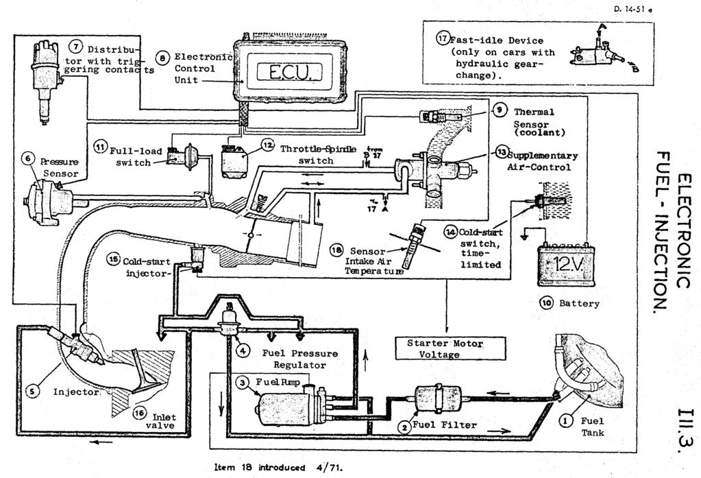
4 -4- Bosch Electronic Fuel Injection We have seen that the purpose of the injection system is to ensure the supply of the correct amount of fuel to the engine in all its varying conditions of use, i.e. from cold-starting, through warming-up, acceleration, normal running, full throttle, over-run, and idling conditions, in varying conditions of temperature and altitude. The injection system is controlled by a device known as the Electronic Control Unit (abbreviated to E.C.U.). This is a box containing several transistorised printed circuits, which receives signals from various sensing devices attached to the engine, which reads and combines these signals, end then sends impulses to the injectors. None of the units is adjustable; if faulty they are replaced. They are tested (except the ECU) by a Bosch Tester,EFAW 228. There are two supply channels to the engine, one for air and one for fuel. AIR CIRCUIT. (Illustration 1) Air enters the air filter, to the right of the engine, passes through a. flexible hose to a metal housing in which is a single throttle-valve (butterfly) operated by a cam and a. cable from the accelerator pedal. From the throttle housing extend 4 air-tubes of equal length, this assembly is the Air Inlet Manifold. The four ends of the manifold pipes are connected by short hoses to Inlet Elbows secured to the cylinder head. Adjustment of Idling:- screw adjustment affects airflow only, (there is no mixture screw); the idling-air channel bypasses the throttle-valve, in the throttle valve housing. (Screw facing forwards). The Fast Idle on cars with hydraulic gearchange:- another air-channel bypasses the Supplementary Air Control (the S.A.C. at the lower LH side of engine, provides the necessary air supply during the warming-up period). FUEL CIRCUIT. (Illustration 2) From the Tank, (1), fuel is drawn through a paper Fuel Filter (2), fitted in the fuel line (change every miles) by the Electric Fuel Pump(3); the filter and pump are under the RH body sidemember. The pump sends fuel along the supply line to the engine, and the fuel pressure is regulated to 28.5 psi (2 kg/cm 2 ) by a Fuel Pressure Regulator (4) fitted to the LH side of the cylinder head. The output of the Pump is considerably more than the engine requires, and the surplus passes through the Fuel-Pressure Regulator and returns to the tank; this ring-main system minimises the chance of vapour-locking. From the pressurised fuel line are four branches, each connected to one Injector (5) for each of the four cylinders, another branch is connected to the Cold Starting Injector (16) fitted in the throttle valve housing. The injectors all have spring-loaded needle-valves which are opened by solenoids; they have constant lift and the fuel is supplied under constant pressure, so that the amount of fuel expelled depends only on the period of time during which the injectors are open.
5 The four main injectors inject behind the inlet valves (17)(port injection); They are opened by pulses supplied by the Electronic Control Unit. They open in two pairs, i.e. two at a time; Nos 1 and 3 inject together, when No.1 is on the inlet stroke the fuel. mixture enters directly at this time piston No.3 is on the exhaust stroke and the fuel mixture waits behind No.3 inlet valve until it opens. Similarly, Nos 2 and 4 inject simultaneously. This is done to simplify the electronic circuits in the ECU., and has no adverse effect on. performance. (Ill.4) The Cold Starting Injector. (16) in the throttle-valve housing is energised by a Relay (Impulse Relay), while the starter motor is in use, and provided that the engine-coolant temperature is less than 20 C 30 C, allowing the Thermal Switch to close; above this temperature the cold start injector does not operate. The Thermal Switch incorporates a device to limit operation of the Cold Starting Injector, to avoid flooding the engine if the Starter motor is used persistently. -5- OPERATION OF INJECTION SYSTEM (Illustration 3) The ECU has to sense the needs of the engine, it does this by receiving signals which indicate: 1) The absolute pressure in the Inlet Manifold (this is the air pressure compared to a vacuum); a Pressure Sensor (6) supplies this information, being connected by a hose to the Inlet Manifold (union housing marked S ) downstream from the throttle-valve; this pressure varies with the throttle opening. 2) The speed of the engine; Triggering Contacts on the shaft of the Ignition Distributor (7) supply this information. The ECU receives these signals, passes them through its internal circuits, creates and sends pulses to the Injectors (5) which cause them to open for a certain time; the quantity of fuel injected depends on the width, (that is the duration) of the pulse supplied to the injector by the E.C.U. On cars with hydraulic gearchange a Fast Idle Air Channel bypasses the Supplementary Air Control (13); the air volume is adjusted by the Fast Idle Screw, and cut off by the Fast Idle Device (17). Apart from normal running, different mixture strengths are required at different times and for different conditions. It is also necessary to introduce compensation for variations of battery voltage, otherwise injection times would vary and the mixture would be incorrect. These various requirements are met by a series of circuits in the ECU which correct the pulse width in accordance with the signals received, cut off the pulses when the accelerator pedal is released, restart pulses when the engine speed is below 1100 rpm, and so on. The ECU, by the triggering impulses from the distributor, senses the engine speed and controls the operation of the Fuel Pump accordingly. When the engine is being started, or is idling, it has only its own internal friction to overcome; but this friction varies with temperature, and the colder the engine, the more fuel and air it will need to run; a Thermal Switch allows the Cold Starting Injector to inject fuel; the Thermal Sensor & the Supplementary Air Control maintain the required balance of fuel and air as the engine warms up. An Intake Air Temperature Sensor, fitted from April 1971, supplies a signal from which the ECU corrects the fuel supply to correspond to the mass of the intake air.
6 -6- Sequence of operation from cold starting (temperature below 68 F): Switch on ignition; General Feed Relay energised, injection system can operate, ECU energised. Fuel pump Relay energises Fuel Pump, operates for 1 second (timed by ECU). Thermal Switch is cold, therefore switch is closed, and Cold Starting Injector can function, (Injection duration limited according to temperature). "Throttle~shut" switch in Throttle Spindle Switch is closed. Thermal Sensor is cold, so it signals ECU to supply a rich mixture, Supplementary Air Control is cold, so air port is open, to balance additional fuel. Full-Load Switch is closed. Operate Starter Motor Impulse - Relay for Cold-Starting Injector energised, Cold-starting Injector injects; - When engine speed exceeds 100 rpm, ECU switches fuel pump on, sensing engine speed from signals from Triggering Contacts on Distributor. ECU supplies pulses to injectors which inject fuel. Pulses are started by signals from 1 triggering contact, & stopped by responses frog Pressure Sensor. engine starts to run. Full-Load Switch opens. Release Starter Motor Control:- Cold starting injection ceases. Engine running:- Pressure Sensor senses change of inlet manifold pressure due to Supplementary Air, signals ECU to adjust injection pulse width accordingly. Engine warms up:- Thermal Sensor signals ECU to reduce fuel supply, until at 70 C quantity is normal, and Supplementary Air Control reduces supplementary sir until at 70 C quantity is normal, and Pressure Sensor senses change in air manifold pressure and signals ECU to correct its pulses. Acceleration: When throttle valve opens, Pressure Sensor senses rise in inlet ~ pressure and signals ECU to increase supply of fuel, but this signal, due to. delay in air movement in hose and capsules, arrives too late for instant response. The Throttle Spindle Switch sends additional impulses to the Switching circuit and to the pulse correction circuit in the ECU, which in turn supplies additional pulses to the injectors. The circuits are so arranged that these additional pulses cease when the signals from the Pressure Sensor take effect; the more quickly the throttle is opened, the more rapid the additional pulses (Note: when the throttle is being closed, a switch in the Throttle Spindle Switch opens and no additional pulses are supplied). If a clogged air-filter reduces airflow the Pressure Sensor senses the lower pressure and signals the ECU to reduce the fuel supply. - Full Load requirement:- when the throttle valve is more than 2/3 open the difference between atmospheric pressure and inlet manifold pressure causes the Full Load Switch to close, signalling the ECU to supply more fuel. Use of pressure differential compensates for changes of altitude. Fuel cutoff on overrun (engine braking):- When the accelerator pedal is released completely and the throttle shuts, the Throttle Shut switch in the Throttle Spindle Switch closes and signals the ECU to cut off the supply of pulses altogether to minimise atmospheric pollution end to avoid wasting fuel; this it does until it learns from the distributor triggering contacts that the engine speed has fallen to 1100 rpm,
7 -7-, or below, when it starts injection again to ensure that the engine will idle. If, for example on a slope, the car then starts to gain speed again, the ECU will cut off the fuel supply again, but not until the engine speed has reached 1800 rpm; these two different speeds are chosen so as to avoid intermittent power-on and power-off conditions which would occur if the car s speed were such as to make the engine run at slightly above & below 1100 rpm. GENERAL NOTES. 1) As long as the Injection System is in use, the fuel pressure is regulated to 28.5 psi by the Fuel. Pressure Regulator. 2) The output from the Fuel Pump is considerably greater than the maximum consumption of the engine, therefore once the Fuel Supply Pressure has reached its level of 28.5 psi, fuel is constantly being returned to the tank. With the engine idling, the operation of the Fuel-Pressure Regulator can be heard distinctly. 3) When the installation of electronic injection is being developed for a given engine, numerous tests are carried out to obtain maximum power and minimum consumption in all various operating conditions which can arise. The circuits of the Electronic Control Units used for development work have adjustable settings, and when optimum results have been achieved these settings are built into the Electronic Control Units for production use. In addition to running conditions, account is taken of the various legal requirements on atmospheric pollution. 4) The results of fitting this system are appreciable: a) With the exact metering of fuel to each cylinder the engine runs more smoothly. b) The engine can be driven in all gears from idling speed on; maximum torque is at 2500 rpm, you can drive in a high gear at low speed, although of course, acceleration is limited by the gear ratio in use; c) Even from cold the engine pulls smoothly. d) Fuel economy: typical comparisons between a carburetted DS 21 and. a DS 21 Injection, both driven in the same way:- - DIN Consumption, average Standard. Injection mph mpg mpg - Touring with 2 people and 1 cwt of luggage: Average 55.9 mph mpg mpg - Average 46.6 mph mpg mpg But of course, if you use the extra power available, you burn more fuel. e) Acceleration: Typical acceleration times are: mph: 8.4 secs mph: 12.0 secs.
8
9
10
11
Simple Carburettor Fuel System for a Piston Engine. And how it works
 Simple Carburettor Fuel System for a Piston Engine And how it works Inlet Exhaust Tank PISTON ENGINE Carburettor Fuel System Filler Cap COCKPIT FUEL GAUGE E FUEL 1/2 F Filler Neck Tank Cavity FUEL LEVEL
CHECKING THE ELECTRONIC FUEL INJECTION SYSTEM.
 CHECKING THE ELECTRONIC FUEL INJECTION SYSTEM. IMPORTANT:- No checks can be carried out without the use of the Special Bosch EF AW 220 Test Unit, which enables every part of the Electronic Fuel Injection
Fuel control. The fuel injection system tasks. Starting fuel pump (FP)
") 1 Fuel control The fuel injection system tasks - To provide fuel - To distribute the fuel between the cylinders - To provide the correct quantity of fuel Starting fuel pump (FP) The control module (1)
1 Fuel control The fuel injection system tasks - To provide fuel - To distribute the fuel between the cylinders - To provide the correct quantity of fuel Starting fuel pump (FP) The control module (1)
EMISSION CONTROL (AUX. EMISSION CONTROL DEVICES) H6DO
 H6DO") EMISSION CONTROL (AUX. EMISSION CONTROL DEVICES) H6DO SYSTEM OVERVIEW 1. System Overview There are three emission control systems, which are as follows: Crankcase emission control system Exhaust emission
EMISSION CONTROL (AUX. EMISSION CONTROL DEVICES) H6DO SYSTEM OVERVIEW 1. System Overview There are three emission control systems, which are as follows: Crankcase emission control system Exhaust emission
Fuel Metering System Component Description
 1999 Chevrolet/Geo Tahoe - 4WD Fuel Metering System Component Description Purpose The function of the fuel metering system is to deliver the correct amount of fuel to the engine under all operating conditions.
Chapter 4 Part D: Fuel and exhaust systems - Magneti Marelli injection
 4D 1 Chapter 4 Part D: Fuel and exhaust systems - Magneti Marelli injection Contents Accelerator cable - removal and..................... 11 Air cleaner element - renewal..............................
NEW FEATURES 3E E ENGINE. 1. Description 12 TERCEL NEW FEATURES
 12 TERCEL NEW FEATURES NEW FEATURES 3E E ENGINE 1. Description The 3E E engine is based on the 1.5 liter, 12 valve, OHC 3E engine, but with fuel injection, ignition timing and other engine functions controlled
EMISSION CONTROL (AUX. EMISSION CONTROL DEVICES) H4DOTC
 H4DOTC") EMISSION CONTROL (AUX. EMISSION CONTROL DEVICES) H4DOTC SYSTEM OVERVIEW 1. System Overview There are three emission control systems, which are as follows: Crankcase emission control system Exhaust emission
EMISSION CONTROL (AUX. EMISSION CONTROL DEVICES) H4DOTC SYSTEM OVERVIEW 1. System Overview There are three emission control systems, which are as follows: Crankcase emission control system Exhaust emission
5. Control System CONTROL SYSTEM FUEL INJECTION (FUEL SYSTEM) A: GENERAL FU(H4DOTC)-29
 A: GENERAL FU(H4DOTC)-29") W1860BE.book Page 29 Tuesday, January 28, 2003 11:01 PM 5. Control System A: GENERAL The ECM receives signals from various sensors, switches, and other control modules. Using these signals, it determines
W1860BE.book Page 29 Tuesday, January 28, 2003 11:01 PM 5. Control System A: GENERAL The ECM receives signals from various sensors, switches, and other control modules. Using these signals, it determines
TECHNICAL DATA. COMPRESSION RATUI 9,5/1 WEIGHT ready to fly CONSUMPTION at 5400RPM 5,6litres/h POWER at 6200RPM
 VICTOR 1 SUPER This handbook aims to bring to the attention of key technical, functional and maintenance of your motor VICTOR 1. Read carefully the following pages, will be synonymous with safety, reliability
EMISSION CONTROL (AUX. EMISSION CONTROL DEVICES) H4SO
 H4SO") EMISSION CONTROL (AUX. EMISSION CONTROL DEVICES) H4SO SYSTEM OVERVIEW 1. System Overview There are three emission control systems, which are as follows: Crankcase emission control system Exhaust emission
EMISSION CONTROL (AUX. EMISSION CONTROL DEVICES) H4SO SYSTEM OVERVIEW 1. System Overview There are three emission control systems, which are as follows: Crankcase emission control system Exhaust emission
Error codes Diagnostic plug Read-out Reset Signal Error codes
 Error codes Diagnostic plug Diagnostic plug: 1 = Datalink LED tester (FEN) 3 = activation error codes (TEN) 4 = positive battery terminal (+B) 5 = ground Read-out -Connect LED tester to positive battery
Motorcycle parts compatibility on ebay.co.uk
 Motorcycle parts compatibility on ebay.co.uk Review the full list of categories and subcategories in which you can list motorcycle and scooter parts. Last updated: 10 August 2016 Motorcycle Parts (10063)
VS403 INSTRUCTIONS FOR: VACUUM AND PRESSURE TEST / BRAKE BLEEDING UNIT MODEL: SAFETY INSTRUCTIONS INTRODUCTION & CONTENTS. fig.1
 INSTRUCTIONS FOR: VACUUM AND PRESSURE TEST / BRAKE BLEEDING UNIT MODEL: VS403 Thank you for purchasing a Sealey product. Manufactured to a high standard this product will, if used according to these instructions
TUNE-UP - DIESEL Isuzu Trooper II IDENTIFICATION ENGINE IDENTIFICATION TESTING ENGINE COMPRESSION ADJUSTMENTS VALVE CLEARANCE
 TUNE-UP - DIESEL 1986 Isuzu Trooper II 1986 Isuzu Diesel 4 Tune-Up TUNE-UP P UP 2.2L, 2.2L Turbo, Trooper II 2.2L Turbo IDENTIFICATION ENGINE IDENTIFICATION Engine serial number is stamped on front part
Fuel and exhaust systems 4A 21
 Fuel and exhaust systems 4A 21 15.40 Unscrew the union nuts and disconnect the fuel feed and return hoses from the manifold 41 Disconnect the injector wiring harness connector and the vacuum hose from
SI unit. Supplementary unit unit. in Ib Ibf Ibfft psi qt(us) F. kg N Nm bar 1 C
 F. kg N Nm bar 1 C") SI unit mm kg N Nm bar 1 C Supplementary unit unit in Ib Ibf Ibfft psi qt(us) F Technical data Carburettor Carburettor type Single carburettor Plerburg Special tools 8393035 Adjusting toot, for metering
SI unit mm kg N Nm bar 1 C Supplementary unit unit in Ib Ibf Ibfft psi qt(us) F Technical data Carburettor Carburettor type Single carburettor Plerburg Special tools 8393035 Adjusting toot, for metering
Rover SD1 Efi System Fuel Supply Components - Explanation and Testing of the Fuel Pump, Filter and Fuel Pressure Regulator
 Rover SD1 Efi System Fuel Supply Components - Explanation and Testing of the Fuel Pump, Filter and Fuel Pressure Regulator Introduction Some of the notes here are repetitious in order to review the components
PIERBURG. Carburetor: 2E3
 PIERBURG Carburetor: 2E3 1 fast idle adjusting screw 2 throttle lever 3 fuel mixture adjusting screw 4 main body 5 idle cut off valve 6 stop screw 7 accelerator pump cover 8 diaphragm 9 spring 10 valve
5. Control System CONTROL SYSTEM FUEL INJECTION (FUEL SYSTEM) A: GENERAL. FU(STi)-27
 A: GENERAL. FU(STi)-27") W1860BE.book Page 27 Tuesday, January 28, 2003 11:01 PM 5. Control System A: GENERAL The ECM receives signals from various sensors, switches, and other control modules. Using these signals, it determines
W1860BE.book Page 27 Tuesday, January 28, 2003 11:01 PM 5. Control System A: GENERAL The ECM receives signals from various sensors, switches, and other control modules. Using these signals, it determines
Combustion process Emission cleaning Fuel distribution Glow plugs Injectors Low and high pressure pumps
 Page 1 of 16 S60 (-09), 2004, D5244T, M56, L.H.D, YV1RS799242356771, 356771 22/1/2014 PRINT Combustion process Emission cleaning Fuel distribution Glow plugs Injectors Low and high pressure pumps Fuel
COOLING SYSTEM - V8. Cooling system component layout DESCRIPTION AND OPERATION
 Cooling system component layout 26-2-2 DESCRIPTION AND OPERATION 1 Heater matrix 2 Heater return hose 3 Heater inlet hose 4 Heater inlet pipe 5 Throttle housing 6 Connecting hose 7 Throttle housing inlet
AN EXPLANATION OF CIRCUITS CARTER YH HORIZONTAL CLIMATIC CONTROL CARBURETER
 AN EXPLANATION OF CIRCUITS CARTER YH HORIZONTAL CLIMATIC CONTROL CARBURETER The Carter Model YH carbureter may be compared with a Carter YF downdraft carbureter with the circuits rearranged to operate
ENGINE CONTROL SYSTEM. 1. General ENGINE 3VZ FE ENGINE
 ENGINE 3VZ FE ENGINE 69 ENGINE CONTROL SYSTEM 1. General The engine control system for the 3VZ FE engine has the same basic construction and operation as for the 2VZ FE engine. However, the sequential
51. absolute pressure sensor
 51. absolute pressure sensor Function The absolute pressure sensor measures the atmospheric pressure. Specifications supply voltage: 5 V output voltage sea level: 3.5-4.5 V output voltage at 2000m: 2.5-3.5
1983 BMW 320i. 1.8L 4-CYL 1983 Engines - 1.8L 4-Cylinder Engines - 1.8L 4-Cylinder
 ENGINE IDENTIFICATION 1.8L 4-CYL 1983 Engines - 1.8L 4-Cylinder For engine repair procedures not covered in this article, see ENGINE OVERHAUL PROCEDURES - GENERAL INFORMATION article in the GENERAL INFORMATION
PARTIAL ENGINE ASSY (2TR FE)
") COMPONENTS 147 1421Z01 Clip Hood Subassy x9 Radiator Support to Frame Seal LH 30 (306, 22) 30 (306, 22) Fan and Generator V Belt 5.0 (51, 44 in. lbf) Fan Shroud Fan Pulley Fan w/ Fluid Coupling PRE RUNNER
COMPONENTS 147 1421Z01 Clip Hood Subassy x9 Radiator Support to Frame Seal LH 30 (306, 22) 30 (306, 22) Fan and Generator V Belt 5.0 (51, 44 in. lbf) Fan Shroud Fan Pulley Fan w/ Fluid Coupling PRE RUNNER
1993 ENGINE PERFORMANCE Service & Adjustment Specifications. EuroVan
 Article Text ARTICLE BEGINNING 1993 ENGINE PERFORMANCE Service & Adjustment s EuroVan INTRODUCTION Use this article to quickly find specifications related to servicing and on-vehicle adjustments. This
CHAPTER 6 IGNITION SYSTEM
 CHAPTER 6 CHAPTER 6 IGNITION SYSTEM CONTENTS PAGE Faraday s Law 02 The magneto System 04 Dynamo/Alternator System 06 Distributor 08 Electronic System 10 Spark Plugs 12 IGNITION SYSTEM Faraday s Law The
Internal Combustion Engines
 Internal Combustion Engines The internal combustion engine is an engine in which the burning of a fuel occurs in a confined space called a combustion chamber. This exothermic reaction of a fuel with an
Honda Accord/Prelude
 Honda Accord/Prelude 1984-1995 In Tank Fuel Pumps TEST 1. Turn the ignition OFF. 2. On the Accord, remove the screws securing the underdash fuse box to its mount. Remove the fuel cut off relay from the
INDEX TECHNICAL SPECIFICATIONS 2 SPECIAL TOOLS 3-4 PERIODIC MAINTENANCE 5 LUBRICANTS 6 TROUBLESHOOTING 7-14 TIGHTENING TORQUE TABLE 15
 INDEX TECHNICAL SPECIFICATIONS 2 SPECIAL TOOLS 3-4 PERIODIC MAINTENANCE 5 LUBRICANTS 6 TROUBLESHOOTING 7-14 TIGHTENING TORQUE TABLE 15 ENGINE DISASSEMBLY 16-24 ENGINE REASSEMBLY 25-37 SPECIAL 3-SHOE CLUTCH
Section 13 - E. 1 of 18. Engine Systems
 Engine Systems 1 of 18 ENGINE FUEL SYSTEM Introduction The fuel system uses electronic, hydraulic and mechanical functions to regulate the power and adapt it to the requirements at any one time. Air pressure
ESCONDIDO FIRE DEPT TRAINING MANUAL Section DRIVER OPERATOR Page 1 of 13 Pumps and Accessory Equipment Revised
 DRIVER OPERATOR Page 1 of 13 PUMPS AND ACCESSORY EQUIPMENT Pumps are designed for many different purposes. In order to understand the proper application and operation of a pump in a given situation, firefighters
Engine Cooling. Cooling System Component Layout. https://myvpn.dealerconnection.com/extdealerlrprod/xml/parsexml.jsp,danainfo=gtr.fran...
 Page 1 of 5 Published : Apr 28, 2004 Engine Cooling Cooling System Component Layout Item Part Number Description 1 - Heater hose, inlet and outlet 2 - Heater hose, inlet and outlet for vehicles with rear
 www.thecarproblems.com/automotive-service-centre How You Diagnose Your Car Problems And Save Money A Quick Look At An Automotive Service Turbo For Your Car - Benefits, Precautions And Just How Does It
1983 Mazda RX-7 GSL TUNE-UP' 'Mazda Rotary
 TESTING ENGINE COMPRESSION The manufacturer recommends using a special compression tester (49 0820 280K). Compression testers for piston engines will read only the highest pressure of the 3 combustion
TUNE-UP - 4-CYL Jeep Cherokee IDENTIFICATION ENGINE IDENTIFICATION TUNE-UP NOTES TESTING ENGINE COMPRESSION SPARK PLUGS
 TUNE-UP - 4-CYL 1988 Jeep Cherokee 1988 Jeep 4 Tune-Up TUNE-UP All Models IDENTIFICATION ENGINE IDENTIFICATION Engine can be identified by the 4th character of the Vehicle Identification Number (VIN).
Repair Manual 11/99 PS-34. Page 1
 Repair Manual /99 PS-4 Page Table of contents Index Technical Data page Special tools 4 Repair instructions, general 0 Chain brake 6 0 Centrifugal clutch 8 0 Oil pump 9-04 Ignition system - 0 Starting
TECHNICAL MANUAL L-JETRONIC FUEL INJECTION SYSTEM PORSCHE 912E
 TECHNICAL MANUAL L-JETRONIC FUEL INJECTION SYSTEM PORSCHE 912E 1 TABLE OF CONTENTS 1.0 Introduction to L-Jetronic Fuel Injection 2.0 L-Jetronic Fuel Injection Theory of Operation 3.0 L-Jetronic Component
Evaporative Emissions
 Page 1 of 6 Published : Apr 8, 2005 Evaporative Emissions 4.4L V8 Evaporative Emissions Component Layout Item Part Number 1 - Fuel filler head 2 - DMTL pump filter (NAS only) 3 - Fuel tank vent hose to
Automobile section, showing different parts in detail. and miscellaneous devices.
 SECTION VII Nos. 97 112 Automobile section, showing different parts in detail. and miscellaneous devices. Hydraulic jack MECHANICAL MODELS 43 Section VII 97. Automobile engine starter. This device known
A. Perform a vacuum gauge test to determine engine condition and performance.
 ENGINE REPAIR UNIT 2: ENGINE DIAGNOSIS, REMOVAL, AND INSTALLATION LESSON 2: ENGINE DIAGNOSTIC TESTS NOTE: Testing the engine s mechanical condition is required when the cause of a problem is not located
BS5582 VACUUM PUMP AND BRAKE BLEEDER KIT Instructions
 RELEVANT PRODUCTS OF BRAKE SYSTEM SERVICE Motorcycle Service Tools BS5630 Brake Fluid Tester BS0245 BS5800 Brake Fluid Condition Tester Detaching Tool Motorcycle Service Tools BS9870 30mm Disc Brake Spreader
FUEL INJECTION SYSTEM - MULTI-POINT
 FUEL INJECTION SYSTEM - MULTI-POINT 1988 Jeep Cherokee 1988 Electronic Fuel Injection JEEP MULTI-POINT 4.0L Cherokee, Comanche, Wagoneer DESCRIPTION The Multi-Point Electronic Fuel Injection (EFI) system
E - THEORY/OPERATION - TURBO
 E - THEORY/OPERATION - TURBO 1995 Volvo 850 1995 ENGINE PERFORMANCE Volvo - Theory & Operation 850 - Turbo INTRODUCTION This article covers basic description and operation of engine performance-related
SPECIFICATIONS TEST AND ADJUSTMENT SPECIFICATIONS SPECIFICATIONS ENGINE FD620D, K SERIES
 ENGINE FD620D, K SERIES SPECIFICATIONS SPECIFICATIONS TEST AND ADJUSTMENT SPECIFICATIONS Engine Oil Pressure Sensor Activates............................... 98 kpa (14.2 psi) Oil Pressure While Cranking
Fuel System (Central SFI)
") Page 1 of 6 1997 GMC Truck GMC K Pickup - 4WD Chevy Pickup, GMC Pickup, Suburban, Tahoe, Yukon (VIN C/K) Service Manual Engine Engine Controls - 5.0L, 5.7L, and 7.4L Description and Operation Document
Page 1 of 6 1997 GMC Truck GMC K Pickup - 4WD Chevy Pickup, GMC Pickup, Suburban, Tahoe, Yukon (VIN C/K) Service Manual Engine Engine Controls - 5.0L, 5.7L, and 7.4L Description and Operation Document
SPECIFICATIONS TEST AND ADJUSTMENT SPECIFICATIONS SPECIFICATIONS ENGINE FD620D, K SERIES
 TEST AND ADJUSTMENT Engine Oil Pressure Sensor Activates............................... 98 kpa (14.2 psi) Oil Pressure While Cranking (Minimum).......................... 28 kpa (4 psi) Oil Pressure.....................................
26 - COOLING SYSTEM CONTENTS ENGINE COOLING - DESCRIPTION... 3 ENGINE COOLING - OPERATION... 9 COOLING SYSTEM FAULTS... 1
 26 - COOLING SYSTEM CONTENTS Page LAND ROVER V8 DESCRIPTION AND OPERATION ENGINE COOLING - DESCRIPTION... 3 ENGINE COOLING - OPERATION... 9 FAULT DIAGNOSIS COOLING SYSTEM FAULTS... 1 REPAIR COOLANT - DRAIN
4.0L CEC SYSTEM Jeep Cherokee DESCRIPTION OPERATION FUEL CONTROL DATA SENSORS & SWITCHES
 4.0L CEC SYSTEM 1988 Jeep Cherokee 1988 COMPUTERIZED ENGINE Controls ENGINE CONTROL SYSTEM JEEP 4.0L MPFI 6-CYLINDER Cherokee, Comanche & Wagoneer DESCRIPTION The 4.0L engine control system controls engine
5. Engine Control Module (ECM) I/O Signal
 I/O Signal") 5. A: ELECTRICAL SPECIFICATION B134 B135 B136 B137 17 16 15 14 13 12 11 10 9 8 27 26 25 24 23 22 21 20 19 18 34 33 32 31 30 29 28 19 18 17 16 15 14 13 12 11 10 9 8 27 26 25 24 23 22 21 20 35 34 33 32 31
5. A: ELECTRICAL SPECIFICATION B134 B135 B136 B137 17 16 15 14 13 12 11 10 9 8 27 26 25 24 23 22 21 20 19 18 34 33 32 31 30 29 28 19 18 17 16 15 14 13 12 11 10 9 8 27 26 25 24 23 22 21 20 35 34 33 32 31
(3) (4) (6) (5) (10) (9) (8) (7)
 (4) (6) (5) (10) (9) (8) (7)") 3. Fuel System A: GENERAL The fuel pressurized by the fuel tank inside pump is delivered to each fuel injector by way of the fuel pipe and fuel filter. Fuel injection pressure is regulated to an optimum
3. Fuel System A: GENERAL The fuel pressurized by the fuel tank inside pump is delivered to each fuel injector by way of the fuel pipe and fuel filter. Fuel injection pressure is regulated to an optimum
MULTIPOINT FUEL INJECTION (MPI) <4G9>
 <4G9>") MULTIPOINT FUEL INJECTION (MPI) 13C-1 MULTIPOINT FUEL INJECTION (MPI) CONTENTS GENERAL................................. 2 Outline of Changes............................ 2 GENERAL INFORMATION...................
MULTIPOINT FUEL INJECTION (MPI) 13C-1 MULTIPOINT FUEL INJECTION (MPI) CONTENTS GENERAL................................. 2 Outline of Changes............................ 2 GENERAL INFORMATION...................
Troubleshooting the Transmission Hydraulic System
 Testing and Adjusting IT28F INTEGRATED TOOLCARRIER POWER TRAIN Testing And Adjusting Introduction Reference: For Specifications with illustrations, refer to SENR5974, IT28F Integrated Toolcarrier Power
Ignition control. The ignition system tasks. How is the ignition coil charge time and the ignition setting regulated?
 1 Ignition control The ignition system tasks To transform the system voltage (approximately 14 V) to a sufficiently high ignition voltage. In electronic systems this is normally above 30 kv (30 000 V).
Systems Operation Testing and Adjusting
 KENR6225-01 April 2008 Systems Operation Testing and Adjusting 402D-403D-404D Industrial Engine GG (Engine) GH (Engine) GJ (Engine) GK (Engine) GL (Engine) GM (Engine) GN (Engine) GP (Engine) GQ (Engine)
Focus on Training Section: Unit 2
 All Pump Types Page 1 1. Title Page Learning objectives Become familiar with the 4 stroke cycle Become familiar with diesel combustion process To understand how timing affects emissions To understand the
Introducing the Sea-Doo 4-TEC SUPERCHARGED
 Introducing the Sea-Doo 4-TEC SUPERCHARGED 185HP & MASSIVE TORQUE iame41-1.doc 29Mar03 Page 1 of 2 Another Sea-Doo watercraft first and only. Introducing the 185hp, GTX 4-TEC SUPERCHARGED PWC. The 4-TEC
G85CS Parts list. Frank Kyul, Netherlands
 G85CS Parts list Frank Kyul, Netherlands http://home.wanadoo.nl/fxkuyl/ CYLINDER BARREL & HEAD 022298 Barrel Cylinder 1 022515 Washer Cylinder Base 1 015351 Nut. Sleeve Cylinder Head 4 042157 Washer Sleeve
service bulletin MCM 7.4L Bravo, MIE 7.4L Inboard GM Generation V Engine Specifications No. 91-6
 service bulletin TO: SERVICE MANAGER MECHANICS PARTS MANAGER No. 91-6 MCM 7.4L Bravo, MIE 7.4L Inboard GM Generation V Engine Specifications NOTE: Generation V Engines Have the Fuel Pump Mounted on the
MULTIPORT FUEL SYSTEM (MFI) <2.4L ENGINE>
 <2.4L ENGINE>") 13B-1 GROUP 13B MULTIPORT FUEL SYSTEM (MFI) CONTENTS GENERAL DESCRIPTION 13B-2 CONTROL UNIT 13B-5 SENSOR 13B-7 ACTUATOR 13B-24 FUEL INJECTION CONTROL 13B-31 IGNITION TIMING AND CONTROL FOR
13B-1 GROUP 13B MULTIPORT FUEL SYSTEM (MFI) CONTENTS GENERAL DESCRIPTION 13B-2 CONTROL UNIT 13B-5 SENSOR 13B-7 ACTUATOR 13B-24 FUEL INJECTION CONTROL 13B-31 IGNITION TIMING AND CONTROL FOR
Manual. Engine SOLO type i
 for the Engine SOLO type Serial - no.... Manufactured... Aircraft - type... Registration no.... Owner... Log of revisions no. Edition date revised page no. date of entry 1 01.09.2010 1-9 01. September
Motronic September 1998
 The Motronic 1.8 engine management system was introduced with the 1992 Volvo 960. The primary difference between this Motronic system and the previous generation of Volvo LH-Jetronic engine management
Lotus Service Notes Section EMR
 ENGINE MANAGEMENT SECTION EMR Lotus Techcentre Sub-Section Page Diagnostic Trouble Code List EMR.1 3 Component Function EMR.2 7 Component Location EMR.3 9 Diagnostic Guide EMR.4 11 CAN Bus Diagnostics;
COMPONENT LOCATOR > DISASSEMBLED VIEWS
 Page 1 of 45 2006 Pontiac Grand Prix 3.8L Eng Base Service Manual: ENGINE MECHANICAL - 3.8L COMPONENT LOCATOR > DISASSEMBLED VIEWS Fig 1: Engine Block Component Views Callout Component Name 100 Engine
Illustrated Parts List Industrial/Commercial to
 FORM MS-9479 6/95 REPLACES FORM MS-9479 10/94 FILE IN SECT. 2 OF SERVICE MANUAL 402700 to 402799 Illustrated Parts List Industrial/Commercial Model Series 402700 to 402799 TYPE NUMBERS 1115 through 1117,
MODEL NUMBER AND IDENTIFICATION. Pag. 5 CHARACTERISTICS CHARACTERISTIC POWER, TORQUE AND SPECIFIC CONSUMPTION CURVES
 MODEL NUMBER AND IDENTIFICATION CHARACTERISTICS CHARACTERISTIC POWER, TORQUE AND SPECIFIC CONSUMPTION CURVES MAINTENANCE - RECOMMENDED OIL TYPE - REFILLING POSSIBLE CAUSES AND TROUBLE SHOOTING OVERALL
TILLOTSON LTD., CLASH INDUSTRIAL ESTATE, TRALEE, CO. KERRY, IRELAND PHONE: FAX:
 TILLOTSON LTD., CLASH INDUSTRIAL ESTATE, TRALEE, CO. KERRY, IRELAND PHONE: +353 66 7121911 FAX: +353 66 7124503 e-mail: sales@tillotson.ie HR SERIES SERVICE MANUAL INTRODUCTION Tillotson has developed
Sales : Mobile : The Zenith 24 T-2 carburettor
 The Zenith 24 T-2 carburettor is an up draught carburettor, developed principally for use on your Ferguson TEA20 (Vaaljapie) tractor. It can be supplied in several versions, the main variations being the
Arona 15 hp (1968) marine engine Lombardini 9LD560 Arona CM 10/B
 marine engine Lombardini 9LD560 Arona CM 10/B") Index Arona 15 hp (1968) marine engine Lombardini 9LD560 Arona CM 10/B Sections Index.. Page 1 Specifications. Page 2 Operation.. Page 3 Maintenance Page 4 Controls Page 5 Fuel system Page 6 Injector pump
Index Arona 15 hp (1968) marine engine Lombardini 9LD560 Arona CM 10/B Sections Index.. Page 1 Specifications. Page 2 Operation.. Page 3 Maintenance Page 4 Controls Page 5 Fuel system Page 6 Injector pump
INSTRUCTIONS FOR: VACUUM TESTER AND BRAKE BLEEDING KIT. MODEL No. VS4021.V2 1. SAFETY 2. INTRODUCTION 3. CONTENTS
 INSTRUCTIONS FOR: VACUUM TESTER AND BRAKE BLEEDING KIT MODEL No. VS4021.V2 Thank you for purchasing a Sealey product. Manufactured to a high standard, this product will, if used according to these instructions,
CHAPTER 2 : ESSENTIAL CHARACTERISTICS OF THE VEHICLE AND ENGINE AND INFORMATION CONCERNING THE CONDUCT OF TESTS
 CHAPTER 2 : ESSENTIAL CHARACTERISTICS OF THE VEHICLE AND ENGINE AND INFORMATION CONCERNING THE CONDUCT OF TESTS 1.0 Description of the Vehicle - 1.1 Trade name or mark of the vehicle - 1.2 Vehicle type
Technical Note 3676A CB1N
 Technical Note 3676A CB1N Basic manual: Workshop Repair Manual 345 and Technical Note 3286A Features of Renault Clio Sport SPL lighter version (see manufacturer's plate) For parts not dealt with in this
C - SPECIFICATIONS Subaru SVX INTRODUCTION CAPACITIES ENGINE PERFORMANCE Subaru Service & Adjustment Specifications
 C - SPECIFICATIONS 1992 Subaru SVX 1992 ENGINE PERFORMANCE Subaru Service & Adjustment Specifications Justy, Legacy, Loyale, SVX INTRODUCTION Use this article to quickly find specifications related to
SERVICE DATA CHAIN SAW CS-450. (Serial number : and after) CONTENTS INTRODUCTION. Reference No B-01 REVISED: ISSUED:
 CONTENTS INTRODUCTION. Reference No B-01 REVISED: ISSUED:") 01-45B-01 1 0 SERVICE DATA CHAIN SAW (Serial number : 36000001 and after) INTRODUCTION We are constantly working on technical improvement of our products. For this reason, technical data, equipment and
01-45B-01 1 0 SERVICE DATA CHAIN SAW (Serial number : 36000001 and after) INTRODUCTION We are constantly working on technical improvement of our products. For this reason, technical data, equipment and
Technical data. Part Thread (mm) Nm ±10% Tolerance Sidestand
 Nm ±10% Tolerance Sidestand") section 3 - Torque settings Frame torque settings Sidestand Stand sensor bolt 5 Pre-applied threadlocker Stand plate fixing screw M10x25 43 Pre-applied threadlocker Side stand fastening pin Side stand
section 3 - Torque settings Frame torque settings Sidestand Stand sensor bolt 5 Pre-applied threadlocker Stand plate fixing screw M10x25 43 Pre-applied threadlocker Side stand fastening pin Side stand
Module 13: Mechanical Fuel Injection Diagnosis and Repair
 Terms and Definitions Parts of Injection Nozzles Types of Nozzle Valves Operation of an Injection Nozzle Fuel Flow Through the Unit Injector Optional Features on Fuel Injection Pumps Main Parts of a Distributor-Type
FUEL SYSTEM/CARBURETOR/FUEL PUMP
 13 FUEL SYSTEM/CARBURETOR/FUEL PUMP FUEL SYSTEM-------------------------------------------------------------------------------------13-1 SCHEMATIC DRAWING-------------------------------------------------------------------------13-2
Lab #5 4-Cylinder Single Overhead Cam Engine Dissection
 Engr 3 Mission College Faculty: Kate Disney TA: Andrew Dina Lab #5 4-Cylinder Single Overhead Cam Engine Dissection Equipment: 4-Cylinder Mazda 16 Valve SOHC 92 (Manual Transmission) Ratchet with 2 and
Glossary. 116
 Sequential Fuel Injection Sequential means that each injector for each cylinder is triggered only one time during the engine s cycle. Typically the injector is triggered only during the intake stroke.
CHAPTER 1 MECHANICAL ARRANGEMENT
 CHAPTER 1 CHAPTER 1 MECHANICAL ARRANGEMENT CONTENTS PAGE Basic Principals 02 The Crankshaft 06 Piston Attachment 08 Major Assemblies 10 Valve Gear 12 Cam Drive 18 Mechanical Arrangement - Basic Principals
Powertrain DTC Summaries OBD II
 Powertrain DTC Summaries Quick Reference Diagnostic Guide Jaguar X-TYPE 2.5L and 3.0L 2002 Model Year Revised January, 2002: P0706, P0731, P0732, P0733, P0734, P0735, P0740, P1780 POSSIBLE CAUSES Revised
INSTRUCTIONS FOR: VACUUM TESTER AND BRAKE BLEEDING KIT
 INSTRUCTIONS FOR: VACUUM TESTER AND BRAKE BLEEDING KIT MODEL: VS402 Thank you for purchasing a Sealey product. Manufactured to a high standard this product will, if used according to these instructions
3. Fuel System FUEL SYSTEM FUEL INJECTION (FUEL SYSTEM) A: GENERAL. FU(STi)-7
 A: GENERAL. FU(STi)-7") W1860BE.book Page 7 Tuesday, January 28, 2003 11:01 PM 3. Fuel System A: GENERAL The fuel pressurized by the fuel tank inside pump is delivered to each fuel injector by way of the fuel pipe and fuel filter.
W1860BE.book Page 7 Tuesday, January 28, 2003 11:01 PM 3. Fuel System A: GENERAL The fuel pressurized by the fuel tank inside pump is delivered to each fuel injector by way of the fuel pipe and fuel filter.
ENGINE GENERAL ENGINE GENERAL GENERAL OVERVIEW AND OPERATION PROCESS 1. STRUCTURE...
 GENERAL 1. STRUCTURE... 3 OVERVIEW AND OPERATION PROCESS 1. ENGINE CONTROLS COMPONENTS... 2. INTAKE SYSTEM COMPONENTS... 3. EXHAUST SYSTEM COMPONENTS... 4. LUBRICATION SYSTEM COMPONENTS... 5. COOLING SYSTEM
ENGINE AND EMISSION CONTROL
 17-1 GROUP 17 ENGINE AND EMISSION CONTROL CONTENTS ENGINE CONTROL........... 17-3 GENERAL INFORMATION....... 17-3 SERVICE SPECIFICATIONS..... 17-3 ON-VEHICLE SERVICE.......... 17-3 ACCELERATOR CABLE CHECK
SYTY Trouble Code: ALDL INFORMATION
 SYTY Trouble Code: ALDL INFORMATION A -- Ground G -- Fuel Pump B -- Diagnostic Terminal H -- Brake Sense Speed Input F -- TCC M -- Serial Data (special tool needed - Do Not Use) For ECM Trouble Codes,
EMISSION CONTROL VISUAL INSPECTION PROCEDURES
 EMISSION CONTROL VISUAL INSPECTION PROCEDURES 1992 Infiniti G20 1983-98 GENERAL INFORMATION Emission Control Visual Inspection Procedures All Models * PLEASE READ THIS FIRST * This article is provided
Powertrain DTC Summaries EOBD
 Powertrain DTC Summaries Quick Reference Diagnostic Guide Jaguar X-TYPE 2.0 L 2002.25 Model Year Refer to page 2 for important information regarding the use of Powertrain DTC Summaries. Jaguar X-TYPE 2.0
3. At sea level, the atmosphere exerts psi of pressure on everything.
 41 Chapter Gasoline Injection Fundamentals Name Instructor Date Score Objective: After studying this chapter, you will be able to explain the construction, operation, and classifications of modern gasoline
POLESTAR HS Management System
 POLESTAR HS Management System Installation Instructions This document contains the information needed to install and adjust the POLESTAR HS Engine Management System. It assumes that the system already
Drawing A Crankcase. Drawing A Crankcase
 Drawing A Crankcase Drawing A Crankcase 1 4238 020 2901 1 Crankcase 2-4 2 9503 003 0351 2 Grooved ball bearing 15x36.3x11 3 0000 953 6606 3 Stud 4 9630 951 1696 1 Oil seal 15x26x7 5 4238 020 2605 1 Crankcase,
service bulletin MCM 350 Magnum Alpha, MCM 5.7L Bravo, MIE 350 Magnum Tournament Ski Inboard Specifications No. 91-8
 service bulletin TO: SERVICE MANAGER MECHANICS PARTS MANAGER No. 91-8 MCM 350 Magnum Alpha, MCM 5.7L Bravo, MIE 350 Magnum Tournament Ski Inboard Specifications NOTE: These three engines have a steel camshaft
INJECTOR. Edge filter. Leak off nipple. C2I label. Nozzle holder body. Bobbin. Control valve. C2I value. Cap nut. Adaptor plate.
 52 07 INJECTOR The C21 labels including injector characteristics are attached in each injector. These C21 values should be input to ECU by using Scan-i when replacing the ECU or injectors. Special cautions:
XC 450 EFT Model Number A2013KCK4CETT SHARE OUR PASSION.
 2013 XC 450 EFT Model Number A2013KCK4CETT TM SHARE OUR PASSION. TABLE OF CONTENTS 2013 XC 450 EFT Green (Model No. A2013KCK4CETT) FRONT BODY ASSEMBLY... 1 REAR BODY AND TAILLIGHT ASSEMBLY... 2 BUMPER,
REDESIGNED MODULES FOR THE SECTOR AUTOMOBILE UNDER MODULAR EMPLOYABLE SKILLS (MES)
") REDESIGNED MODULES FOR THE SECTOR OF AUTOMOBILE UNDER MODULAR EMPLOYABLE SKILLS (MES) Redesigned in - 2014 By Government of India Directorate General of Employment & Training Ministry of Labour & Employment
REDESIGNED MODULES FOR THE SECTOR OF AUTOMOBILE UNDER MODULAR EMPLOYABLE SKILLS (MES) Redesigned in - 2014 By Government of India Directorate General of Employment & Training Ministry of Labour & Employment
service bulletin MCM 4.3L, 4.3LX Alpha GM Generation II Engine Specifications No
 service bulletin TO: SERVICE MANAGER MECHANICS PARTS MANAGER No. 91-17 MCM 4.3L, 4.3LX Alpha GM Generation II Engine Specifications NOTE: These engines have an electric fuel pump because there is no pad
PARTIAL ENGINE ASSY (2ZZ GE)
") COMPONENTS 14189 140R701 7.0 (71, 62 in. lbf) Cylinder Head Cover No. 2 19 (194, 14) Radiator Support Upper 19 (194, 14) Radiator Hose Inlet Cruise Control Actuator Assy 6.0 (61, 53 in. lbf) Radiator Assy
COMPONENTS 14189 140R701 7.0 (71, 62 in. lbf) Cylinder Head Cover No. 2 19 (194, 14) Radiator Support Upper 19 (194, 14) Radiator Hose Inlet Cruise Control Actuator Assy 6.0 (61, 53 in. lbf) Radiator Assy
The 1.4 ltr. and 1.6 ltr. FSI engine with timing chain
 Service. Self study programme 296 The 1.4 ltr. and 1.6 ltr. FSI engine with timing chain Design and function For Volkswagen, new and further development of engines with direct petrol injection is an important